EP2709882B1 - Control device for a vehicle brake system, and method for operating a vehicle brake system - Google Patents
Control device for a vehicle brake system, and method for operating a vehicle brake system Download PDFInfo
- Publication number
- EP2709882B1 EP2709882B1 EP12710913.0A EP12710913A EP2709882B1 EP 2709882 B1 EP2709882 B1 EP 2709882B1 EP 12710913 A EP12710913 A EP 12710913A EP 2709882 B1 EP2709882 B1 EP 2709882B1
- Authority
- EP
- European Patent Office
- Prior art keywords
- brake
- valve
- braking torque
- generator
- brake system
- Prior art date
- Legal status (The legal status is an assumption and is not a legal conclusion. Google has not performed a legal analysis and makes no representation as to the accuracy of the status listed.)
- Active
Links
Images


Classifications
-
- B—PERFORMING OPERATIONS; TRANSPORTING
- B60—VEHICLES IN GENERAL
- B60T—VEHICLE BRAKE CONTROL SYSTEMS OR PARTS THEREOF; BRAKE CONTROL SYSTEMS OR PARTS THEREOF, IN GENERAL; ARRANGEMENT OF BRAKING ELEMENTS ON VEHICLES IN GENERAL; PORTABLE DEVICES FOR PREVENTING UNWANTED MOVEMENT OF VEHICLES; VEHICLE MODIFICATIONS TO FACILITATE COOLING OF BRAKES
- B60T1/00—Arrangements of braking elements, i.e. of those parts where braking effect occurs specially for vehicles
- B60T1/02—Arrangements of braking elements, i.e. of those parts where braking effect occurs specially for vehicles acting by retarding wheels
- B60T1/10—Arrangements of braking elements, i.e. of those parts where braking effect occurs specially for vehicles acting by retarding wheels by utilising wheel movement for accumulating energy, e.g. driving air compressors
-
- B—PERFORMING OPERATIONS; TRANSPORTING
- B60—VEHICLES IN GENERAL
- B60T—VEHICLE BRAKE CONTROL SYSTEMS OR PARTS THEREOF; BRAKE CONTROL SYSTEMS OR PARTS THEREOF, IN GENERAL; ARRANGEMENT OF BRAKING ELEMENTS ON VEHICLES IN GENERAL; PORTABLE DEVICES FOR PREVENTING UNWANTED MOVEMENT OF VEHICLES; VEHICLE MODIFICATIONS TO FACILITATE COOLING OF BRAKES
- B60T8/00—Arrangements for adjusting wheel-braking force to meet varying vehicular or ground-surface conditions, e.g. limiting or varying distribution of braking force
- B60T8/17—Using electrical or electronic regulation means to control braking
-
- B—PERFORMING OPERATIONS; TRANSPORTING
- B60—VEHICLES IN GENERAL
- B60L—PROPULSION OF ELECTRICALLY-PROPELLED VEHICLES; SUPPLYING ELECTRIC POWER FOR AUXILIARY EQUIPMENT OF ELECTRICALLY-PROPELLED VEHICLES; ELECTRODYNAMIC BRAKE SYSTEMS FOR VEHICLES IN GENERAL; MAGNETIC SUSPENSION OR LEVITATION FOR VEHICLES; MONITORING OPERATING VARIABLES OF ELECTRICALLY-PROPELLED VEHICLES; ELECTRIC SAFETY DEVICES FOR ELECTRICALLY-PROPELLED VEHICLES
- B60L7/00—Electrodynamic brake systems for vehicles in general
- B60L7/24—Electrodynamic brake systems for vehicles in general with additional mechanical or electromagnetic braking
- B60L7/26—Controlling the braking effect
-
- B—PERFORMING OPERATIONS; TRANSPORTING
- B60—VEHICLES IN GENERAL
- B60T—VEHICLE BRAKE CONTROL SYSTEMS OR PARTS THEREOF; BRAKE CONTROL SYSTEMS OR PARTS THEREOF, IN GENERAL; ARRANGEMENT OF BRAKING ELEMENTS ON VEHICLES IN GENERAL; PORTABLE DEVICES FOR PREVENTING UNWANTED MOVEMENT OF VEHICLES; VEHICLE MODIFICATIONS TO FACILITATE COOLING OF BRAKES
- B60T11/00—Transmitting braking action from initiating means to ultimate brake actuator without power assistance or drive or where such assistance or drive is irrelevant
- B60T11/10—Transmitting braking action from initiating means to ultimate brake actuator without power assistance or drive or where such assistance or drive is irrelevant transmitting by fluid means, e.g. hydraulic
- B60T11/12—Transmitting braking action from initiating means to ultimate brake actuator without power assistance or drive or where such assistance or drive is irrelevant transmitting by fluid means, e.g. hydraulic the transmitted force being varied therein
-
- B—PERFORMING OPERATIONS; TRANSPORTING
- B60—VEHICLES IN GENERAL
- B60T—VEHICLE BRAKE CONTROL SYSTEMS OR PARTS THEREOF; BRAKE CONTROL SYSTEMS OR PARTS THEREOF, IN GENERAL; ARRANGEMENT OF BRAKING ELEMENTS ON VEHICLES IN GENERAL; PORTABLE DEVICES FOR PREVENTING UNWANTED MOVEMENT OF VEHICLES; VEHICLE MODIFICATIONS TO FACILITATE COOLING OF BRAKES
- B60T11/00—Transmitting braking action from initiating means to ultimate brake actuator without power assistance or drive or where such assistance or drive is irrelevant
- B60T11/10—Transmitting braking action from initiating means to ultimate brake actuator without power assistance or drive or where such assistance or drive is irrelevant transmitting by fluid means, e.g. hydraulic
- B60T11/16—Master control, e.g. master cylinders
- B60T11/232—Recuperation valves
-
- B—PERFORMING OPERATIONS; TRANSPORTING
- B60—VEHICLES IN GENERAL
- B60T—VEHICLE BRAKE CONTROL SYSTEMS OR PARTS THEREOF; BRAKE CONTROL SYSTEMS OR PARTS THEREOF, IN GENERAL; ARRANGEMENT OF BRAKING ELEMENTS ON VEHICLES IN GENERAL; PORTABLE DEVICES FOR PREVENTING UNWANTED MOVEMENT OF VEHICLES; VEHICLE MODIFICATIONS TO FACILITATE COOLING OF BRAKES
- B60T13/00—Transmitting braking action from initiating means to ultimate brake actuator with power assistance or drive; Brake systems incorporating such transmitting means, e.g. air-pressure brake systems
- B60T13/10—Transmitting braking action from initiating means to ultimate brake actuator with power assistance or drive; Brake systems incorporating such transmitting means, e.g. air-pressure brake systems with fluid assistance, drive, or release
- B60T13/58—Combined or convertible systems
- B60T13/585—Combined or convertible systems comprising friction brakes and retarders
- B60T13/586—Combined or convertible systems comprising friction brakes and retarders the retarders being of the electric type
-
- B—PERFORMING OPERATIONS; TRANSPORTING
- B60—VEHICLES IN GENERAL
- B60T—VEHICLE BRAKE CONTROL SYSTEMS OR PARTS THEREOF; BRAKE CONTROL SYSTEMS OR PARTS THEREOF, IN GENERAL; ARRANGEMENT OF BRAKING ELEMENTS ON VEHICLES IN GENERAL; PORTABLE DEVICES FOR PREVENTING UNWANTED MOVEMENT OF VEHICLES; VEHICLE MODIFICATIONS TO FACILITATE COOLING OF BRAKES
- B60T13/00—Transmitting braking action from initiating means to ultimate brake actuator with power assistance or drive; Brake systems incorporating such transmitting means, e.g. air-pressure brake systems
- B60T13/10—Transmitting braking action from initiating means to ultimate brake actuator with power assistance or drive; Brake systems incorporating such transmitting means, e.g. air-pressure brake systems with fluid assistance, drive, or release
- B60T13/66—Electrical control in fluid-pressure brake systems
- B60T13/68—Electrical control in fluid-pressure brake systems by electrically-controlled valves
- B60T13/686—Electrical control in fluid-pressure brake systems by electrically-controlled valves in hydraulic systems or parts thereof
-
- B—PERFORMING OPERATIONS; TRANSPORTING
- B60—VEHICLES IN GENERAL
- B60T—VEHICLE BRAKE CONTROL SYSTEMS OR PARTS THEREOF; BRAKE CONTROL SYSTEMS OR PARTS THEREOF, IN GENERAL; ARRANGEMENT OF BRAKING ELEMENTS ON VEHICLES IN GENERAL; PORTABLE DEVICES FOR PREVENTING UNWANTED MOVEMENT OF VEHICLES; VEHICLE MODIFICATIONS TO FACILITATE COOLING OF BRAKES
- B60T15/00—Construction arrangement, or operation of valves incorporated in power brake systems and not covered by groups B60T11/00 or B60T13/00
- B60T15/02—Application and release valves
- B60T15/025—Electrically controlled valves
-
- B—PERFORMING OPERATIONS; TRANSPORTING
- B60—VEHICLES IN GENERAL
- B60T—VEHICLE BRAKE CONTROL SYSTEMS OR PARTS THEREOF; BRAKE CONTROL SYSTEMS OR PARTS THEREOF, IN GENERAL; ARRANGEMENT OF BRAKING ELEMENTS ON VEHICLES IN GENERAL; PORTABLE DEVICES FOR PREVENTING UNWANTED MOVEMENT OF VEHICLES; VEHICLE MODIFICATIONS TO FACILITATE COOLING OF BRAKES
- B60T8/00—Arrangements for adjusting wheel-braking force to meet varying vehicular or ground-surface conditions, e.g. limiting or varying distribution of braking force
- B60T8/32—Arrangements for adjusting wheel-braking force to meet varying vehicular or ground-surface conditions, e.g. limiting or varying distribution of braking force responsive to a speed condition, e.g. acceleration or deceleration
- B60T8/34—Arrangements for adjusting wheel-braking force to meet varying vehicular or ground-surface conditions, e.g. limiting or varying distribution of braking force responsive to a speed condition, e.g. acceleration or deceleration having a fluid pressure regulator responsive to a speed condition
- B60T8/40—Arrangements for adjusting wheel-braking force to meet varying vehicular or ground-surface conditions, e.g. limiting or varying distribution of braking force responsive to a speed condition, e.g. acceleration or deceleration having a fluid pressure regulator responsive to a speed condition comprising an additional fluid circuit including fluid pressurising means for modifying the pressure of the braking fluid, e.g. including wheel driven pumps for detecting a speed condition, or pumps which are controlled by means independent of the braking system
- B60T8/4072—Systems in which a driver input signal is used as a control signal for the additional fluid circuit which is normally used for braking
-
- B—PERFORMING OPERATIONS; TRANSPORTING
- B60—VEHICLES IN GENERAL
- B60T—VEHICLE BRAKE CONTROL SYSTEMS OR PARTS THEREOF; BRAKE CONTROL SYSTEMS OR PARTS THEREOF, IN GENERAL; ARRANGEMENT OF BRAKING ELEMENTS ON VEHICLES IN GENERAL; PORTABLE DEVICES FOR PREVENTING UNWANTED MOVEMENT OF VEHICLES; VEHICLE MODIFICATIONS TO FACILITATE COOLING OF BRAKES
- B60T1/00—Arrangements of braking elements, i.e. of those parts where braking effect occurs specially for vehicles
- B60T1/02—Arrangements of braking elements, i.e. of those parts where braking effect occurs specially for vehicles acting by retarding wheels
-
- B—PERFORMING OPERATIONS; TRANSPORTING
- B60—VEHICLES IN GENERAL
- B60T—VEHICLE BRAKE CONTROL SYSTEMS OR PARTS THEREOF; BRAKE CONTROL SYSTEMS OR PARTS THEREOF, IN GENERAL; ARRANGEMENT OF BRAKING ELEMENTS ON VEHICLES IN GENERAL; PORTABLE DEVICES FOR PREVENTING UNWANTED MOVEMENT OF VEHICLES; VEHICLE MODIFICATIONS TO FACILITATE COOLING OF BRAKES
- B60T2270/00—Further aspects of brake control systems not otherwise provided for
- B60T2270/60—Regenerative braking
- B60T2270/604—Merging friction therewith; Adjusting their repartition
-
- B—PERFORMING OPERATIONS; TRANSPORTING
- B60—VEHICLES IN GENERAL
- B60W—CONJOINT CONTROL OF VEHICLE SUB-UNITS OF DIFFERENT TYPE OR DIFFERENT FUNCTION; CONTROL SYSTEMS SPECIALLY ADAPTED FOR HYBRID VEHICLES; ROAD VEHICLE DRIVE CONTROL SYSTEMS FOR PURPOSES NOT RELATED TO THE CONTROL OF A PARTICULAR SUB-UNIT
- B60W10/00—Conjoint control of vehicle sub-units of different type or different function
- B60W10/18—Conjoint control of vehicle sub-units of different type or different function including control of braking systems
- B60W10/184—Conjoint control of vehicle sub-units of different type or different function including control of braking systems with wheel brakes
- B60W10/188—Conjoint control of vehicle sub-units of different type or different function including control of braking systems with wheel brakes hydraulic brakes
-
- B—PERFORMING OPERATIONS; TRANSPORTING
- B60—VEHICLES IN GENERAL
- B60W—CONJOINT CONTROL OF VEHICLE SUB-UNITS OF DIFFERENT TYPE OR DIFFERENT FUNCTION; CONTROL SYSTEMS SPECIALLY ADAPTED FOR HYBRID VEHICLES; ROAD VEHICLE DRIVE CONTROL SYSTEMS FOR PURPOSES NOT RELATED TO THE CONTROL OF A PARTICULAR SUB-UNIT
- B60W2510/00—Input parameters relating to a particular sub-units
- B60W2510/08—Electric propulsion units
- B60W2510/083—Torque
-
- B—PERFORMING OPERATIONS; TRANSPORTING
- B60—VEHICLES IN GENERAL
- B60W—CONJOINT CONTROL OF VEHICLE SUB-UNITS OF DIFFERENT TYPE OR DIFFERENT FUNCTION; CONTROL SYSTEMS SPECIALLY ADAPTED FOR HYBRID VEHICLES; ROAD VEHICLE DRIVE CONTROL SYSTEMS FOR PURPOSES NOT RELATED TO THE CONTROL OF A PARTICULAR SUB-UNIT
- B60W2710/00—Output or target parameters relating to a particular sub-units
- B60W2710/18—Braking system
- B60W2710/182—Brake pressure, e.g. of fluid or between pad and disc
-
- B—PERFORMING OPERATIONS; TRANSPORTING
- B60—VEHICLES IN GENERAL
- B60W—CONJOINT CONTROL OF VEHICLE SUB-UNITS OF DIFFERENT TYPE OR DIFFERENT FUNCTION; CONTROL SYSTEMS SPECIALLY ADAPTED FOR HYBRID VEHICLES; ROAD VEHICLE DRIVE CONTROL SYSTEMS FOR PURPOSES NOT RELATED TO THE CONTROL OF A PARTICULAR SUB-UNIT
- B60W30/00—Purposes of road vehicle drive control systems not related to the control of a particular sub-unit, e.g. of systems using conjoint control of vehicle sub-units, or advanced driver assistance systems for ensuring comfort, stability and safety or drive control systems for propelling or retarding the vehicle
- B60W30/18—Propelling the vehicle
- B60W30/18009—Propelling the vehicle related to particular drive situations
- B60W30/18109—Braking
- B60W30/18127—Regenerative braking
Description
Die Erfindung betrifft eine Steuervorrichtung für ein Bremssystem eines Fahrzeugs. Des Weiteren betrifft die Erfindung ein Verfahren zum Betreiben eines Bremssystems eines Fahrzeugs.The invention relates to a control device for a brake system of a vehicle. Furthermore, the invention relates to a method for operating a brake system of a vehicle.
In der
Außerdem beschreibt die
Die Erfindung schafft eine Steuervorrichtung für ein Bremssystem eines Fahrzeugs mit den Merkmalen des Anspruchs 1, ein Bremssystem für ein Fahrzeug mit den Merkmalen des Anspruchs 4 und ein Verfahren zum Betreiben eines Bremssystems eines Fahrzeugs mit den Merkmalen des Anspruchs 5.The invention provides a control system for a braking system of a vehicle having the features of
Die vorliegende Erfindung ermöglicht ein Transferieren eines aus dem Hauptbremszylinder herausgedrückten Bremsflüssigkeitsvolumens in das Bremsmediumreservoir unter Umgehung des mindestens einen Radbremszylinders. Das Transferieren erfolgt somit ohne ein Aufbauen eines Restdrucks in dem mindestens einen Radbremszylinder, bzw. eines hydraulischen "Rest-Bremsmoments" an einem Rad.The present invention makes it possible to transfer a brake fluid volume pressed out of the master brake cylinder into the brake medium reservoir while bypassing the at least one wheel brake cylinder. The transfer thus takes place without building up a residual pressure in the at least one wheel brake cylinder, or a hydraulic "residual braking torque" on a wheel.
Das mittels der vorliegenden Erfindung realisierbare Bremssystem ist als ein mit einem minimalen Änderungsaufwand erweitertes Einfachsystem umschreibbar. Damit ist es möglich, eine ausreichende rekuperative Effizienz bei minimalen Mehrkosten zu erzielen. Die Steigerung der rekuperativen Effizienz ist bei der vorliegenden Erfindung hauptsächlich darin begründet, dass das vorgeschlagene Bremssystem den Fahrer bei der Modulationsaufgabe im Falle eines entfallenden regenerativen Bremsmoments unterstützt. Die erfindungsgemäße Technologie ist in der Lage, auf ein reduziertes rekuperatives Bremsmoment der rekuperativen Bremse, beispielsweise aufgrund eines vollen Energiespeichers und/oder einer Fahrzeuggeschwindigkeit unter der zum rekuperativen Bremsen benötigten Mindestgeschwindigkeit, zu reagieren. Insbesondere ist dies ausführbar, ohne dass der Bremsweg verlängert wird oder der Fahrer eine Rückwirkung bei der Betätigung des Bremsbetätigungselements bemerkt.The braking system which can be realized by means of the present invention can be rewritten as a simple system which is expanded with a minimum change effort. This makes it possible to achieve sufficient recuperative efficiency with minimal additional costs. The increase in recuperative efficiency in the present invention is mainly due to the fact that the proposed braking system assists the driver in the modulation task in the event of an omitted regenerative braking torque. The inventive technology is able to respond to a reduced recuperative braking torque of the recuperative brake, for example, due to a full energy storage and / or a vehicle speed below the minimum speed required for recuperative braking. In particular, this is executable without the braking distance is extended or the driver notices a reaction in the operation of the brake operating member.
Es wird darauf hingewiesen, dass die Ausführbarkeit der erfindungsgemäßen Technologie keinen an dem Bremsbetätigungselement, dem Bremskraftverstärker oder in dem Hauptbremszylinder ausgebildeten Leerweg erfordert. Somit kann der Fahrer auch in der Rückfallebene schnell in das Bremssystem einbremsen.It should be noted that the practicability of the technology according to the invention does not require any free travel formed on the brake actuator, the brake booster or the master cylinder. Thus, the driver can brake quickly in the fallback level in the braking system.
Die vorliegende Erfindung weist einen Jump-In auf. Dies ist so umschreibbar, dass das Bremssystem ein Bremsbetätigungselement aufweist, welches derart an den Hauptbremszylinder angeordnet ist, dass während des Betätigens des Bremsbetätigungselements mit einer Betätigungsstärke ungleich Null aber unter der Mindestbetätigungsstärke, bei welcher die auf das Bremsbetätigungselement aufgebrachte Fahrerbremskraft auf den Hauptbremszylinder-Kolben übertragbar ist, eine Kraftübertragung zwischen dem Bremsbetätigungselement und Hauptbremszylinder-Kolben nicht vorliegt/(nahezu) unterbunden ist. Dies ermöglicht ein Verblenden während eines Nichtvorliegens/einer Unterbindung einer Kraftübertragung zwischen dem Bremsbetätigungselement und dem Hauptbremszylinder-Kolben. Somit ist für den Fahrer kein verändertes Bremsgefühl bei einem regenerativen Bremsen anstelle eines hydraulischen Bremsens wahrnehmbar. Aufgrund der nicht-vorliegenden/(nahezu) unterbundenen Kraftübertragung zwischen dem Hauptbremszylinder-Kolben und dem Bremsbetätigungselement, beispielsweise aufgrund einer vernachlässigbaren (evtl. fehlenden) mechanischen Kopplung bei einer Betätigungsstärke unter dem Mindestbetätigungsstärke, stützt sich die durch den hydraulischen Druckaufbau verursachte Gegenkraft nicht am Bremsbetätigungselement, sondern lediglich an der Verstärkungskraft des Bremskraftverstärkers ab. Die Veränderung der Gegenkraft ist somit für den Fahrer am Bremsbetätigungselement nicht wahrnehmbar. Gleichzeitig hat der Fahrer bei der vorliegenden Erfindung die Möglichkeit, mittels eines Betätigens des Bremsbetätigungselements mit zumindest der Mindestbetätigungsstärke direkt in den Hauptbremszylinder hinein zu bremsen. Somit ist selbst bei einer Funktionsbeeinträchtigung des Bremskraftverstärkers, beispielsweise aufgrund einer Beeinträchtigung der Stromversorgung des Bremssystems, noch ein sicheres Abbremsen des Fahrzeugs gewährleistet.The present invention has a jump-in. This is so circumscribed that the brake system comprises a brake actuator, which is arranged on the master cylinder such that during actuation of the brake actuator with an actuating force not equal to zero but below the minimum actuation strength at which the force applied to the brake actuator driver braking force to the master cylinder piston transferable is, a power transmission between the brake actuator and master cylinder piston is not present / (almost) prevented. This allows for blending during a lack of / inhibition of a power transmission between the Brake actuator and the master cylinder piston. Thus, the driver is not aware of a changed brake feeling in a regenerative braking instead of a hydraulic brake. Due to the non-present / (almost) suppressed power transmission between the master cylinder piston and the brake actuator, for example, due to a negligible (possibly missing) mechanical coupling at an operating force below the minimum operating force, the counterforce caused by the hydraulic pressure build-up is not supported on the brake actuator , but only from the boosting force of the brake booster. The change in the counterforce is thus imperceptible to the driver on the brake actuator. At the same time, in the present invention, the driver has the possibility of braking by means of an actuation of the brake actuating element with at least the minimum operating force directly into the master brake cylinder. Thus, even with a functional impairment of the brake booster, for example due to an impairment of the power supply of the brake system, still a safe braking of the vehicle guaranteed.
Man kann dies auch als ein Verblenden innerhalb des Jump-In-Bereichs (des Bremskraftverstärkers) bezeichnen. Der Jump-In-Bereich stellt einen Betätigungsbereich des Bremskraftverstärkers, wie beispielsweise eines Vakuum-Boosters, dar, bei welchem keine/eine vernachlässigbare mechanische Kopplung zwischen dem Bremsbetätigungselement und dem Hauptbremszylinder-Kolben existiert. Trotzdem wird bereits im Jump-In-Bereich in den Hauptbremszylinder gebremst. Somit weist das Bremssystem keinen Leerweg auf und ist insbesondere in der Rückfallebene sicher betreibbar.This can also be referred to as blending within the jump-in area (of the brake booster). The jump-in area constitutes an operating range of the brake booster, such as a vacuum booster, in which there is no negligible mechanical coupling between the brake operating member and the master cylinder piston. Nevertheless, it is already braked in the jump-in area in the master cylinder. Thus, the brake system has no free travel and is safe to operate especially in the fallback level.
Mittels der erfindungsgemäßen Technologie können auch Bremsanforderungen ohne eine Betätigung des Bremsbetätigungselements (aktive Druckaufbauten) ausgeführt werden.By means of the technology according to the invention, braking requirements can also be carried out without an actuation of the brake actuating element (active pressure assemblies).
Weitere Merkmale und Vorteile der vorliegenden Erfindung werden nachfolgend anhand der Figuren erläutert. Es zeigen:
- Fig. 1
- eine schematische Darstellung einer Ausführungsform der Steuervorrichtung;
- Fig. 2A bis 2G
- eine schematische Gesamtdarstellung, drei schematische Teildarstellungen und drei Koordinatensysteme zum Erläutern einer Ausführungsform eines Bremssystems mit der Steuervorrichtung;
- Fig. 3
- ein Flussdiagramm zum Darstellen einer ersten Ausführungsform des Verfahrens;
- Fig. 4A bis 4D
- vier Koordinatensysteme zum Darstellen einer zweiten Ausführungsform des Verfahrens;
- Fig. 5A bis 5D
- vier Koordinatensysteme zum Erläutern einer dritten Ausführungsform des Verfahrens; und
- Fig. 6A bis 6D
- vier Koordinatensysteme zum Erläutern einer vierten Ausführungsform des Verfahrens.
- Fig. 1
- a schematic representation of an embodiment of the control device;
- Figs. 2A to 2G
- an overall schematic representation, three partial schematic representations and three coordinate systems for explaining an embodiment of a brake system with the control device;
- Fig. 3
- a flowchart for illustrating a first embodiment of the method;
- Figs. 4A to 4D
- four coordinate systems for illustrating a second embodiment of the method;
- Figs. 5A to 5D
- four coordinate systems for explaining a third embodiment of the method; and
- FIGS. 6A to 6D
- Four coordinate systems for explaining a fourth embodiment of the method.
Die in
Das erste Ventil kann beispielsweise ein stetig regelbares/stellbares/steuerbares Ventil sein. Insbesondere ist als stetig regelbares Ventil ein Ventil verwendbar, welches zusätzlich zu einem geschlossenen Zustand (geschlossenen Ventilmodus) in mindestens zwei unterschiedliche geöffnete Zustände (geöffnete Ventilmodi) steuerbar/regelbar ist. Die Einsetzbarkeit der Steuervorrichtung ist jedoch nicht auf einen bestimmten Typ eines stetig regelbaren Ventils als erstes Ventil limitiert.The first valve may, for example, be a continuously controllable / adjustable / controllable valve. In particular, a valve which can be controlled / regulated in addition to a closed state (closed valve mode) into at least two different open states (open valve modes) can be used as a continuously controllable valve. However, the applicability of the control device is not limited to a particular type of continuously variable valve as a first valve.
Als Flüssigkeitsspeichervorrichtung ist das erste Ventil über zumindest eine Saugleitung mit einem Bremsmediumreservoir des Bremssystems verbunden. Unter dem Bremsmediumreservoir kann eine Flüssigkeitsspeichervorrichtung verstanden werden, welche mit dem Hauptbremszylinder über mindestens eine Bremsflüssigkeit-Austauschverbindung, wie beispielsweise eine Schnüffelbohrung, verbunden ist. Vorzugsweise ist eine Bremsflüssigkeit druckfrei (gegendruckfrei) in das Bremsmediumreservoir transferierbar. In dem Bremsmediumreservoir kann insbesondere der Atmosphärendruck vorliegen. Auf eine vorteilhafte Anordnung des ersten Ventils an dem Bremsmediumreservoir wird unten noch eingegangen.As a liquid storage device, the first valve is connected via at least one suction line to a brake medium reservoir of the brake system. The brake medium reservoir can be understood to mean a fluid storage device which is connected to the master brake cylinder via at least one brake fluid exchange connection, such as a sniffer bore. Preferably, a brake fluid is pressure-free (back pressure-free) in the brake fluid reservoir transferable. In particular, the atmospheric pressure may be present in the brake medium reservoir. On an advantageous arrangement of the first valve to the brake fluid reservoir will be discussed below.
Mittels der Ventilsteuereinrichtung 10 ist somit der erste Soll-Zustand für ein über zumindest eine Saugleitung mit dem Bremsmediumreservoir des Bremssystems als Flüssigkeitsspeichervorrichtung verbundenes erstes Ventil festlegbar. Ein dem ersten Soll-Zustand entsprechendes ersten Steuersignal 14 ist mittels der Ventilsteuereinrichtung 10 an das erste Ventil ausgebbar.By means of the
Das (mindestens eine) Informationssignal 12 kann beispielsweise von einem Fahrzeugbus, einer Generatorsteuerung und/oder einem Generator-Sensor an die Ventilsteuereinrichtung 10 bereitgestellt werden. Eine weitere vorteilhafte Möglichkeit zum Bereitstellen des Informationssignals 12 an die Ventilsteuereinrichtung 10 wird unten noch genauer beschrieben.The (at least one)
Bevorzugter Weise ist die Ventilsteuereinrichtung 10 zusätzlich dazu ausgelegt, unter Berücksichtigung eines ersten Sensorsignals 16a bezüglich einer Betätigungsstärke einer Betätigung eines Bremsbetätigungselements des Bremssystems (durch den Fahrer) einen zweiten Soll-Zustand eines (nicht dargestellten) zweiten Ventils des Bremssystems festzulegen. In diesem Fall ist das zweite Ventil vorzugsweise als Trennventil zwischen dem Hauptbremszylinder und einem Bremskreis des Bremssystems mit dem ersten Ventil und mindestens einem Radbremszylinder angeordnet. Ein dem zweiten Soll-Zustand entsprechendes zweites Steuersignal 18 ist mittels der Ventilsteuereinrichtung 10 an das zweite Ventil ausgebbar. Auf eine vorteilhafte Anordnung des als Trennventil verwendbaren zweiten Ventils wird unten noch eingegangen. Als Alternative oder als Ergänzung zu der Berücksichtigung des ersten Sensorsignals 16a kann bei der Festlegung des zweiten Soll-Zustands mittels der Ventilsteuereinrichtung 10 auch das Informationssignal 12, der erste Soll-Zustand und/oder ein zweites Sensor- und/oder Informationssignal 16b bezüglich mindestens eines ausführbaren Kann-Generator-Bremsmoments berücksichtigbar sein.Preferably, the
In einer vorteilhaften Ausführungsform ist die Ventilsteuereinrichtung 10 zusätzlich dazu ausgelegt, das erste Sensorsignal 16a mit einem vorgegebenen Vergleichsignal bezüglich einer Mindestbetätigungsstärke zu vergleichen. Unter der Mindestbetätigungsstärke kann eine Betätigungsstärke verstanden werden, ab welcher eine auf das Bremsbetätigungselement aufgebrachte Fahrerbremskraft auf einen verstellbaren Hauptbremszylinder-Kolben des Hauptbremszylinders, wie beispielsweise auf den Stangenkolben des Hauptbremszylinders, übertragbar ist. Sofern das erste Sensorsignal 16a unter dem Vergleichssignal liegt (d.h. sofern die Betätigungsstärke unter der Mindestbetätigungsstärke liegt), wird in diesem Fall mittels der Ventilsteuereinrichtung 10 das zweite Ventil so in einen zumindest teilgeöffneten Zustand gesteuert, dass ein aus dem Hauptbremszylinder herausgedrücktes Bremsflüssigkeitsvolumen über das in dem zumindest teilgeöffneten Zustand gesteuerte zweite Ventil in den Bremskreis verschiebbar ist. Des Weiteren kann die Ventilsteuereinrichtung 10 dazu ausgelegt sein, sofern das erste Sensorsignal 16a das Vergleichssignal übersteigt (d.h. sofern die Betätigungsstärke die Mindestbetätigungsstärke übersteigt), das zweite Ventil so in einen geschlossenen Zustand zu steuern, dass eine hydraulische Verbindung zwischen dem Hauptbremszylinder und dem Bremskreis unterbunden ist.In an advantageous embodiment, the
Die Steuervorrichtung ist somit besonders vorteilhaft einsetzbar mit einem Bremssystem bei welchem das Bremsbetätigungselement so an dem Hauptbremszylinder angeordnet ist, dass bei einer Betätigungsstärke der Betätigung ungleich Null aber unter der Mindestbetätigungsstärke keine Fahrerbremskraft auf den (mindestens einen) verstellbaren Hauptbremszylinder-Kolben übertragbar ist. Wie nachfolgend genauer beschrieben wird, kann in diesem Fall ein Generator zum Aufladen einer Fahrzeugbatterie besonders vorteilhaft während einer Betätigung des Bremsbetätigungselements unter der Mindestbetätigungsstärke, bei welcher der Fahrer keine Rückwirkung/Gegenkraft des Bremssystems an dem Bremsbetätigungselement spürt, eingesetzt werden.The control device can thus be used particularly advantageously with a brake system in which the brake actuating element is arranged on the master brake cylinder so that no driver braking force can be transmitted to the (at least one) adjustable master cylinder piston at an actuation strength of the actuator not equal to zero but below the minimum actuation strength. As will be described in more detail below, in this case a generator for charging a vehicle battery can be used particularly advantageously during actuation of the brake actuation element below the minimum actuation level at which the driver does not feel any reaction / counterforce of the brake system on the brake actuation element.
In einer vorteilhaften Weiterbildung umfasst die Steuervorrichtung eine Pumpensteuereinrichtung 20, welche dazu ausgelegt ist, sofern das erste Sensorsignal 16a bei zeitlicher Zunahme der Betätigungsstärke sich dem Vergleichssignal annährt, ein Pumpensteuersignal 22 an eine (nicht skizzierte) Pumpe des Bremssystems auszugeben. Durch das Pumpensteuersignal 22 ist die Pumpe dazu ansteuerbar, ein Bremsflüssigkeitsvolumen aus dem Bremsmediumreservoir über das in dem zumindest teilgeöffneten Zustand vorliegende zweite Ventil in den Hauptbremszylinder zu pumpen. Wie unten genauer ausgeführt wird, ist somit nach einem Verblenden eines Generator-Bremsmoments das zuvor in das Bremsmediumreservoir transferierte Bremsflüssigkeitsvolumen mittels der Pumpe wieder in den Hauptbremszylinder zurückverschiebbar. Auf diese Weise kann gewährleistet werden, dass der Fahrer ab einer Betätigungsstärke gleich der Mindestbetätigungsstärke trotz des zuvor ausgeführten Verblendens des Generator-Bremsmoments ein standardgemäßes Bremsbetätigungsgefühl (Pedalgefühl) hat.In an advantageous development, the control device comprises a
Als Alternative oder als Ergänzung zu der Pumpensteuereinrichtung 20 kann die Steuervorrichtung auch eine Generatorsteuereinrichtung 24 umfassen. Mittels der Generatorsteuereinrichtung 24 kann das auszuübende Generator-Bremsmoment des Generators unter Berücksichtung des ersten Sensorsignals 16a und/oder des zweiten Sensors und/oder Informationssignals 16b bezüglich des mindestens einen ausführbaren Kann-Generator-Bremsmoments festlegbar sein. Anschließend kann ein dem festgelegten auszuübenden Generator-Bremsmoment entsprechendes Generatorsteuersignal 26 an den Generator ausgebbar sein. Ebenso kann von der Generatorsteuereinrichtung 24 das Informationssignal 12 an die Ventilsteuereinrichtung 10 ausgegeben werden.As an alternative or supplement to the
Die Ventilsteuereinrichtung 10 kann zusammen mit der Generatorsteuereinrichtung 24 und/oder der Pumpensteuereinrichtung 20 in eine Auswerteelektronik 28 integriert sein. In diesem Fall entfällt die Notwendigkeit, die Steuereinrichtungen 10, 20 und 24 getrennt mit auszuwertenden Informationen zu versorgen. Die Steuervorrichtung ist jedoch nicht auf die Integration der Steuereinrichtungen 10, 20 und 24 in eine Auswerteelektronik 28 limitiert.The
Die Steuervorrichtung kann insbesondere dazu ausgelegt sein, die Verfahrensschritte der unten genauer beschriebenen Verfahren auszuführen. Bezüglich der mittels der Steuervorrichtung ausführbaren Verfahrensschritte wird deshalb auf die nachfolgende Beschreibung der Verfahren verwiesen.The control device may in particular be designed to carry out the method steps of the methods described in more detail below. Regarding the means of Control device executable method steps is therefore made to the following description of the method.
Auf weiter Vorteile der Steuervorrichtung wird bei der Beschreibung von deren Zusammenwirken mit den Komponenten eines Bremssystems mit Bezug auf die nachfolgende Figur genauer eingegangen.Further advantages of the control device will be discussed in more detail in the description of their interaction with the components of a brake system with reference to the following figure.
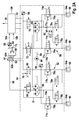
Das in
Das Bremssystem hat einen ersten Bremskreis 50 und einen zweiten Bremskreis 52 mit jeweils zwei Radbremszylindern 54a und 54b. Den beiden Radbremszylindern 54a des ersten Bremskreises 50 sind zwei an der Vorderachse angeordnete Räder 56 zugeordnet. Den beiden Radbremszylindern 54b des zweiten Bremskreises 52 sind die Räder 60 an der Hinterachse zugeordnet. Das hier beschriebene Bremssystem ist jedoch nicht auf eine achsweise Bremskreisaufteilung beschränkt.The brake system has a
Das Bremssystem weist einen Hauptbremszylinder 62 auf, welcher beispielsweise als Tandemhauptbremszylinder ausführbar ist. Bevorzugter Weise umfasst der Hauptbremszylinder 62 einen als Stangenkolben bezeichenbaren ersten verstellbaren Kolben, welcher zumindest teilweise an eine dem ersten Bremskreis 50 zugeordnete erste Druckkammer 62a des Hauptbremszylinders 62 hineinragt, und einen als Schwimmkolben bezeichenbaren zweiten verstellbaren Kolben, der zumindest teilweise in eine dem zweiten Bremskreis 52 zugeordnete zweite Druckkammer 62b des Hauptbremszylinders 62 hineinragt. In einer bevorzugten Ausführungsform ist der Schwimmkolben so verstellbar, dass bei einem Verstellen des Schwimmkolbens in eine erste Richtung das erste Innenvolumen der ersten Druckkammer 62a abnimmt, während das Innenvolumen der zweiten Druckkammer 62b zunimmt. Entsprechend kann über ein Verstellen des Schwimmkolbens in eine zweite Richtung das Innenvolumen der ersten Druckkammer 62a bei einer Abnahme des Innenvolumens der zweiten Druckkammer 62b zunehmen. Außerdem kann in der ersten Druckkammer 62a eine härtere Feder angeordnet sein, sodass ein (leichtes) Betätigen des Bremsbetätigungselements 64 zuerst zu einem Einbremsen in die zweite Druckkammer 62b und in den zweiten Bremskreis 52 führt. Auf die vorteilhafte Nutzung eines derart ausgebildeten Hauptbremszylinders 62 wird unten noch genauer eingegangen. Das Bremssystem ist jedoch nicht auf die Verwendung eines Tandemhauptbremszylinders oder auf eine bestimmte Ausbildung des Hauptbremszylinders 62 beschränkt. Der Hauptbremszylinder 62 kann über mindestens eine Bremsflüssigkeit-Austauschöffnung, wie beispielsweise eine Schnüffelbohrung, mit einem Bremsmediumreservoir 61 verbunden sein.The brake system has a
Das Bremssystem weist ein an einem Hauptbremszylinder 62 angeordnetes Bremsbetätigungselement 64, beispielsweise ein Bremspedal, auf. Vorteilhafterweise ist das Bremsbetätigungselement 64 derart an dem Hauptbremszylinder 62 angeordnet, dass bei einem Betätigen des Bremsbetätigungselements 64 mit zumindest einer Mindestbetätigungsstärke eine auf das Bremsbetätigungselement 64 aufgebrachte Fahrerbremskraft auf einen (nicht skizzierten) verstellbaren Hauptbremszylinder-Kolben des Hauptbremszylinders 62 so übertragbar ist, dass der Hauptbremszylinder-Kolben mittels der Fahrerbremskraft verstellbar ist. Bevorzugter Weise wird mittels dieses Verstellens des Hauptbremszylinder-Kolbens ein Innendruck in mindestens einer Kammer des Hauptbremszylinders 62 gesteigert. Bei dem hier beschriebenen Bremssystem ist das Bremsbetätigungselement 64 zusätzlich derart an dem Hauptbremszylinder 62 angeordnet, dass während des Betätigens des Bremsbetätigungselements mit einer Betätigungsstärke ungleich Null aber unter der Mindestbetätigungsstärke eine Kraftübertragung zwischen dem Bremsbetätigungselement 64 und dem Hauptbremszylinder-Kolben unterbunden ist. Dies gewährleistet den Vorteil, dass der Fahrer während des Betätigens des Bremsbetätigungselements 64 mit der Betätigungsstärke unter der Mindestbetätigungsstärke von dem Hauptbremszylinder 62 und dem mindestens einen daran angebundenen Bremskreis 50 und 52 "entkoppelt" ist, und somit keine Rückwirkung des darin vorliegenden Drucks spürt. Auf die vorteilhafte Einsetzbarkeit dieses Vorteils zum Verblenden eines Generator-Bremsmoments wird unten noch genauer eingegangen. Das Bremssystem ist jedoch nicht auf eine derartige Anordnung des Bremsbetätigungselements 64 an dem Hauptbremszylinder 62 beschränkt.The brake system has a
Bevorzugter Weise umfasst das Bremssystem auch einen Bremsbetätigungselement-Sensor 66, mittels welchem die Betätigungsstärke der Betätigung des Bremsbetätigungselements 64 durch den Fahrer ermittelbar ist. Der Bremsbetätigungselement-Sensor 26 kann beispielsweise einen Pedalwegsensor, einen Differenzwegsensor und/oder einen Stangenwegsensor umfassen. Zur Erfassung der Betätigungsstärke, welche dem Fahrerbremswunsch entspricht, ist jedoch auch eine anders geartete Sensorik anstelle oder zusätzlich zu den hier aufgezählten Sensortypen einsetzbar.The brake system preferably also includes a brake
Das dargestellte Bremssystem weist in einer bevorzugten Ausführungsform noch einen Bremskraftverstärker 68, wie beispielsweise einen Vakuumbremskraftverstärker, auf. Anstelle eines Vakuumbremskraftverstärkers kann das Bremssystem auch einen anderen Typ des Bremskraftverstärkers 68, wie beispielsweise eine hydraulische und/oder eine elektromechanische Verstärkungseinrichtung, aufweisen. Der Bremskraftverstärker 68 kann insbesondere ein stetig regelbarer/stetig steuerbarer Bremskraftverstärker sein.The brake system shown has in a preferred embodiment, a
Mittels des Bremskraftverstärkers 68 ist in der Regel zumindest während des Betätigens des Bremsbetätigungselements 64 unter der Mindestbetätigungsstärke der Hauptbremszylinder-Kolben so verstellbar, dass ein Bremsflüssigkeitsvolumen aus dem Hauptbremszylinder 62 verschiebbar ist. Ein Bremskraftverstärker 68 weist in der Regel zu Beginn seines Betätigungswegs eine unendliche Verstärkung auf. In diesem Bereich besteht eine vernachlässigbare (evtl. keine) mechanische Kopplung zwischen dem Bremsbetätigungselement 64, wie beispielsweise einem Bremspedal, und dem Hauptbremszylinder-Kolben. Man kann dies auch als Nichtvorliegen einer wesentlichen mechanischen Kopplung zwischen Bremsbetätigungselement 64 und dem Bremssystem bezeichnen. Die Fahrerbremskraft wird in diesem Bereich nicht zur Betätigung des Hauptbremszylinders 62, das heißt zum Verstellen des (mindestens einen) Hauptbremszylinder-Kolbens, herangezogen, sondern lediglich zur Steuerung des Bremskraftverstärkers 68 genutzt.By means of the
Der Beginn des Betätigungswegs, in welchem die Betätigungsstärke ungleich Null noch unter der Mindestbetätigung liegt, wird deshalb häufig auch Jump-In-Bereich genannt. Außerhalb des Jump-In-Bereichs existiert eine mechanische Kopplung zwischen dem Bremsbetätigungselement 64 und dem Hauptbremszylinder-Kolben. Die Fahrerbremskraft wird somit außerhalb des Jump-In-Bereichs zum Verstellen des Hauptbremszylinder-Kolbens und somit zum Einbremsen in den mindestens einen Radbremszylinder 54a und 54b genutzt. Dieser Vorgang kann durch die zusätzliche Kraft des Bremskraftverstärkers 68 unterstützt werden.The beginning of the actuation path, in which the non-zero actuation force is still below the minimum actuation, is therefore often called a jump-in range. Outside the jump-in area, there is a mechanical coupling between the
Die Eigenschaft des Bremskraftverstärkers 68 kann somit für ein Einbremsen in den Hauptbremszylinder 62 ohne eine (wesentliche) mechanische Kopplung/Kraftübertragung zwischen dem Bremsbetätigungselement 64 und dem Hauptbremszylinder-Kolben genutzt werden. Somit ist der Beginn des Betätigungswegs mit einer Betätigungsstärke ungleich Null aber unter der Mindestbetätigung, bzw. der Jump-In-Bereich, vorteilhaft für ein Verblenden eines Generator-Bremsmoments verwendbar, wie unten noch ausgeführt wird.The characteristic of the
Wie anhand der
Bei der in
Erst ab einer Betätigungsstärke gleich der Mindestbetätigungsstärke, z.B. bei einem Bremsbetätigungsweg sc gleich dem Mindestbremsweg smin, liegt ein Kraftübertragungskontakt zwischen dem Bremsbetätigungselement 64 und dem (mindestens einen) verstellbaren Kolben 63 des Hauptbremszylinders 62 vor, wie dies in
Wie anhand der
Der Fahrer bremst während des Jump-In-Bereichs JI nur indirekt in den Hauptbremszylinder 62 hinein. Dies ist realisierbar, indem unter Verwendung eines Bremsbetätigungselement-Sensors eine dem Bremsbetätigungsweg s entsprechende Fahrzeugverzögerung a als Soll-Fahrzeugverzögerung festgelegt wird (siehe
Nachfolgend werden mit Bezug zu
Der erste Bremskreis 50 ist mit einem Hauptschaltventil 70 und einem Umschaltventil 72 so ausgebildet, dass der Fahrer über den Hauptbremszylinder 62 direkt in die Radbremszylinder 54a des ersten Bremskreises 50 hineinbremsen kann. Jedem der beiden Radbremszylinder 54a des ersten Bremskreises 50 sind ein Radeinlassventil 74a mit einer parallel dazu verlaufenden Bypassleitung 76a, ein in jeder Bypassleitung 76a angeordnetes Rückschlagventil 77a und ein Radauslassventil 78a zugeordnet. Außerdem umfasst der erste Bremskreis 50 eine erste Pumpe 80, deren Ansaugseite mit den Radauslassventilen 78a verbunden ist und deren Förderseite zu dem Umschaltventil 72 gerichtet ist, eine zwischen den Radauslassventilen 78a und der Pumpe 80 angekoppelte Speicherkammer 82 und ein zwischen der ersten Pumpe 80 und der Speicherkammer 82 angeordnetes Überdruckventil 84.The
Der zweite Bremskreis 52 ist als ein von dem Hauptbremszylinder 62 entkoppelbarer Bremskreis 52 ausgebildet. Dazu weist der zweite Bremskreis 52 (als zweites Ventil) ein Trennventil 86 auf, mittels welchem die Radbremszylinder 54b des zweiten Bremskreises 52, die den Radbremszylindern 54b zugeordneten Radeinlassventile 74b mit parallel angeordneten Bypassleitungen 76b mit Rückschlagventilen 77b und die den Radbremszylinder 54b zugeordneten Radauslassventile 78b von dem Hauptbremszylinder 62 abkoppelbar sind. Über ein Schließen des Trennventils 86 kann verhindert werden, dass der Bremsdruck in den Radbremszylindern 54b des zweiten Bremskreises 52 dem in der zweiten Druckkammer 62b des Hauptbremszylinders 62 vorliegenden Innendruck entspricht.The
Außerdem weist der zweite Bremskreis 52 ein (als erstes Ventil verwendbares) stetig regelbares/verstellbares/steuerbares Ventil 88 und eine zweite Pumpe 90 auf. Anstelle des stetig regelbaren Ventils 88 kann der zweite Bremskreis 52 jedoch auch ein Schaltventil als erstes Ventil 88 haben. Das stetig regelbare Ventil 88 ist über eine Ansaugleitung 89 mit dem Bremsmediumreservoir 61 an dem Hauptbremszylinder 62 hydraulisch verbunden. Die Ansaugseite der zweiten Pumpe 90 ist ebenfalls mit dem Bremsmediumreservoir 61 über eine parallel zu dem stetig regelbaren Ventil 88 und der zweiten Pumpe 90 verlaufende Leitung 91 und die Reservoirleitung 89 hydraulisch so verbunden, dass nach einem Schließen des Trennventils 86 ein Bremsflüssigkeitsvolumen mittels der zweiten Pumpe 90 über die (zumindest teilgeöffneten) Radeinlassventile 74b in die Radbremszylinder 54b des zweiten Bremskreises 52 pumpbar ist. Die Förderseite der zweiten Pumpe 90 ist über das stetig regelbare Ventil 88 so mit dem Bremsmediumreservoir 61 verbunden, dass nach dem Schließen des Trennventils 86 ein Bremsflüssigkeitsvolumen aus den Radbremszylindern 54b des zweiten Bremskreises 52 über die (zumindest teilgeöffneten) Radauslassventile 78b und das (zumindest teilgeöffnete) stetig regelbare Ventil 88 in das Bremsmediumreservoir 61 pumpbar ist.In addition, the
Somit kann nach dem Schließen des Trennventils 86 das hydraulische Bremsmoment der Radbremszylinder 54b des zweiten Bremskreises 52 mittels der zweiten Pumpe 90 und dem stetig regelbaren Ventil 88 aktiv eingestellt werden. Insbesondere kann das hydraulische Bremsmoment der von dem Hauptbremszylinder 62 entkoppelten Radbremszylinder 54b des zweiten Bremskreises 52 entsprechend einer Differenz zwischen einem von dem Fahrer vorgegebenen Soll-Gesamtbremsmoment und einem Ist-Gesamtbremsmoment aus dem Generator-Bremsmoment des Generators und dem hydraulischen Bremsmoment der Radbremszylinder 54a des ersten Bremskreises 50 eingestellt werden.Thus, after closing the
Das in
Die Pumpen 80 und 90 können jeweils als Drei-Kolben-Pumpen auf einer gemeinsamen Welle 94 eines Motors 96 angeordnet sein. Anstelle von Drei-Kolben-Pumpen sind jedoch auch andere Pumpentypen für die Pumpen 80 und 90 verwendbar. Außerdem kann jeder der beiden Bremskreise 50 und 52 noch mindestens einen Drucksensor 98 umfassen.The
Die in den oberen Absätzen beschriebenen Komponenten 70 bis 96 des Bremssystems stellen lediglich Beispiele für eine Ausstattung eines mit der nachfolgend genauer beschriebenen Steuervorrichtung 100 ausgestatteten Bremssystems dar.The
Durch die Verwendung der oben schon beschriebenen Steuervorrichtung 100 mit dem Bremssystem ist eine Vergleichsweise hohe Effizienz bei einer Rekuperation erzielbar:By using the above-described
Mittels eines Schaltens des stetig regelbaren Ventils 88 durch das erste Steuersignal 14 kann ein aus dem Hauptbremszylinder 62 heraus gedrücktes Bremsflüssigkeitsvolumen wahlweise in die Radbremszylinder 54b des zweiten Bremskreises 52 oder in das Bremsmediumreservoir 61 verschoben werden. Man kann dies so umschreiben, dass mittels eines Ansteuerns des stetig regelbaren Ventils 88 durch das erste Steuersignal 14 ein "hydraulischer Leerweg" realisierbar ist. Das Aktivieren des "hydraulischen Leerwegs" durch Öffnen des stetig regelbaren Ventils 88 bewirkt (aufgrund des geringeren Gegendrucks in dem Bremsmediumreservoir 61 gegenüber den Radbremszylindern 54b des zweiten Bremskreises 52) das Verschieben des aus dem Hauptbremszylinder 62 heraus gedrückten Bremsflüssigkeitsvolumens in das Bremsmediumreservoir 61. In diesem Fall findet kein wesentlicher Druckaufbau im Hauptbremszylinder 62 statt. Durch einen minimalen Druck wird Volumen stattdessen in das Bremsmediumreservoir 61 verschoben. Dieser Druck ist so gering (0,0x bar), dass die Radbremszylindern 54a und 54b (Bremszangen) noch deutlich unter ihrem Ansprechdruck sind.By means of a switching of the continuously variable valve 88 by the
Aufgrund des geringeren Gegendrucks in dem Bremsmediumreservoir 61 gegenüber den Radbremszylindern 54a des ersten Bremskreises 50 und der vorteilhaften Verstellbarkeit des Schwimmkolbens bewirkt der "hydraulische Leerweg" auch eine Unterbindung eines hydraulischen Druckaufbaus in dem ersten Bremskreis 50. Das Schalten des stetig regelbaren Ventils 88 durch das erste Steuersignal 14 gewährleistet deshalb, dass bei einer (leichten) Betätigung des Bremsbetätigungselements 64 der Bremsdruck in den Radbremszylindern 54a und 54b beider Bremskreise 50 und 52 nicht gesteigert wird.Due to the lower backpressure in the
Trotzdem kann über den Sensor 66 ein Fahrerbremswunsch verlässlich ermittelt und anschließend mit sehr hoher Effizienz (vollständig oder teilweise) über den Generator umgesetzt werden. Der (nicht skizzierte) Generator kann beispielsweise an der Vorderachse angeordnet sein. Auf diese Weise ist eine Fahrzeugbatterie mittels des Generators aufladbar, ohne dass der von dem Fahrer vorgegebene Fahrerbremswunsch überschritten wird.Nevertheless, via the
Sofern die aktuelle Generatorleistung diese Verzögerung nicht allein aufbringen kann, kann mittels eines Ansteuerns des stetig regelbaren Ventils 88 und der zweiten Pumpe 90 ein zusätzliches hydraulisches Bremsmoment in den beiden Radbremszylindern 54b aufgebaut werden, um der vom Fahrer vorgegebenen Wunschverzögerung zumindest teilweise zu entsprechen. Vorzugsweise kann in diesem Fall die Summe aus den hydraulischen Bremsmomenten und dem Generator-Bremsmoment gleich der vom Fahrer vorgegebenen Wunschverzögerung sein. Mittels des ersten Steuersignals 14 kann das stetig regelbare Ventil 88 gezielt so gesteuert/geschaltet werden, dass über ein Verschieben des aus dem Hauptbremszylinder 62 herausgedrückten Bremsflüssigkeitsvolumens über das zumindest teilgeöffnete stetig regelbare Ventil 88 in das Bremsmediumsreservoir 61 das bevorzugte hydraulische Bremsmoment der Radbremszylinder 54b vorliegt. Bezüglich der genauen Schaltstrategie wird auf die nachfolgend beschriebenen Verfahrensschritte verwiesen.If the current generator power can not apply this delay alone, an additional hydraulic braking torque in the two
Der mittels des Ansteuerns des stetig regelbaren Ventils 88 durch das erste Steuersignal 14 bewirkbare "hydraulische Leerweg" gewährleistet somit die Vorteile eines "mechanischen" Leerwegs. Somit ist es nicht notwendig, einen "mechanischen" Leerweg an dem Hauptbremszylinder 62, an dem Bremskraftverstärker 68 oder an dem Bremsbetätigungselement 64 auszubilden.The "hydraulic free travel" which can be effected by means of the control of the continuously controllable valve 88 by the
Das mit der Steuervorrichtung 100 ausgestattete Bremssystem kann insbesondere auch die nachfolgend beschriebenen Verfahrensschritte ausführen. Bezüglich der Ausführung dieser Verfahrensschritte und ihre Vorteile wird deshalb auf die Beschreibung der weiteren Figuren verwiesen.The brake system equipped with the
Das in
In einem Verfahrensschritt S1 wird ein erster Soll-Zustand eines ersten Ventils des Bremssystems unter Berücksichtigung einer Generator-Bremsmoment-Größe bezüglich eines aktuell ausgeübten oder auszuübenden Generator-Bremsmoments eines Generators festgelegt. Das erste Ventil ist derart mit einem Hauptbremszylinder des Bremssystems und mit einer Flüssigkeitsspeichervorrichtung des Bremssystems verbunden, dass ein Bremsflüssigkeitsvolumen aus dem Hauptbremszylinder über das in einem zumindest teilgeöffneten Zustand gesteuerte erste Ventil in die Flüssigkeitsspeichervorrichtung verschiebbar ist. Das erste Ventil kann insbesondere ein stetig regelbares/steuerbares/stellbares Ventil sein. Das hier beschriebene Verfahren ist jedoch nicht auf die Verwendung eines stetig regelbaren Ventils als erstes Ventil limitiert.In a method step S1, a first desired state of a first valve of the brake system is determined taking into account a generator brake torque quantity with respect to a generator braking torque currently being exerted or to be exerted. The first valve is connected to a master brake cylinder of the brake system and to a fluid storage device of the brake system such that a volume of brake fluid from the master brake cylinder via the in an at least partially open state controlled first valve is slidable into the liquid storage device. The first valve may in particular be a continuously controllable / controllable / adjustable valve. However, the method described here is not limited to the use of a continuously variable valve as the first valve.
Als Flüssigkeitsspeichervorrichtung ist das erste Ventil zumindest über eine Saugleitung mit einem Bremsmediumreservoir des Bremssystems verbunden. Genauere Beschreibungen zu der Ausbildbarkeit des Bremsmediumreservoirs sind oben schon beschrieben.As a liquid storage device, the first valve is connected at least via a suction line to a brake medium reservoir of the brake system. More detailed descriptions of the feasibility of Bremsmediumreservoirs are already described above.
Beispielsweise kann in dem Verfahrensschritt S1 die Generator-Bremsmoment-Größe mit einer vorgegebenen Mindest-Bremsmoment-Größe verglichen werden. Sofern die Generator-Bremsmoment-Größe über der Mindest-Bremsmoment-Größe liegt, wird vorzugsweise das erste Ventil so in den zumindest teilgeöffneten Zustand gesteuert, dass ein aus dem Hauptbremszylinder herausgedrücktes Bremsflüssigkeitsvolumen über das in den zumindest teilgeöffneten Zustand gesteuerte erste Ventil in das Bremsmediumreservoir verschoben wird. Ebenso kann, sofern die Generator-Bremsmoment-Größe unter der Mindest-Bremsmoment-Größe liegt, das erste Ventil so in einen geschlossenen Zustand gesteuert werden, dass eine hydraulische Verbindung zwischen dem Hauptbremszylinder und dem Bremsmediumreservoir unterbunden wird.For example, in the method step S1, the generator braking torque quantity can be compared with a predetermined minimum braking torque quantity. If the generator braking torque quantity is above the minimum braking torque variable, the first valve is preferably controlled in the at least partially opened state such that a brake fluid volume pressed out of the master brake cylinder displaces into the brake medium reservoir via the first valve controlled in the at least partially opened state becomes. Likewise, if the generator braking torque quantity is below the minimum braking torque quantity, the first valve can be controlled in a closed state such that a hydraulic connection between the master brake cylinder and the brake fluid reservoir is prevented.
In einem Verfahrensschritt S2 wird das erste Ventil unter Berücksichtigung des festgelegten ersten Soll-Zustands angesteuert. Beispielsweise kann durch das auf diese Weise in das Bremsmediumreservoir verschobene Bremsflüssigkeitsvolumen verhindert werden, dass das aus dem Hauptbremszylinder herausgedrückte Bremsflüssigkeitsvolumen zu einer Steigerung eines hydraulischen Bremsmoments mindestens eines Radbremszylinders beiträgt. Somit ist mittels des Ansteuerns des ersten Ventils ein "hydraulischer Leerweg" realisierbar, welcher verhindert, dass eine Betätigung eines an dem Hauptbremszylinder angeordneten Bremsbetätigungselements automatisch zu einer Steigerung des Bremsdrucks des mindestens einen Radbremszylinders des Bremssystems führt.In a method step S2, the first valve is actuated taking into account the specified first desired state. For example, can be prevented by the thus displaced in the brake fluid reservoir volume of brake fluid that pushed out of the master cylinder brake fluid volume contributes to an increase of a hydraulic braking torque of at least one wheel brake cylinder. Thus, by means of the activation of the first valve, a "hydraulic free travel" can be realized, which prevents actuation of a brake actuation element arranged on the master brake cylinder from automatically increasing the brake pressure of the at least one wheel brake cylinder of the brake system.
In einem optionalen Verfahrensschritt S3 kann unter Berücksichtigung einer Betätigungsstärke-Größe bezüglich einer Betätigungsstärke einer Betätigung eines Bremsbetätigungselements ein zweiter Soll-Zustand eines zweiten Ventils des Bremssystems festgelegt werden. Anstelle oder als Ergänzung zu der Betätigungsstärke-Größe können auch die Generator-Bremsmoment-Größe, der erste Soll-Zustand und/oder eine Generator-Einsetzinformation bezüglich mindestens eines ausführbaren Kann-Generator-Bremsmoments berücksichtigt werden. (Die Generator-Einsetzinformation wird beispielsweise von mindestens einem an dem Generator und/oder an einer mittels des Generators aufladbaren Batterie angeordneten Sensor und/oder einem Fahrzeugbus bereitgestellt.) Dabei wird der zweite Soll-Zustand festgelegt für ein als zweites Ventil eingesetztes Trennventil zwischen dem Hauptbremszylinder und einem Bremskreis des Bremssystems mit dem ersten Ventil und mindestens einem Radbremszylinder. In einem anschließenden Verfahrensschritt S4 wird dieses zweite Ventil als Trennventil unter Berücksichtigung des festgelegten zweiten Soll-Zustands angesteuert.In an optional method step S3, a second desired state of a second valve of the brake system can be defined, taking into account an amount of actuation magnitude with respect to an actuation amount of an actuation of a brake actuation element. Instead of or as a supplement to the operating force size It is also possible to take into account the generator braking torque quantity, the first desired state and / or a generator insertion information with regard to at least one executable, optional generator braking torque. (The generator insertion information is provided, for example, by at least one sensor arranged on the generator and / or on a battery which can be recharged by the generator and / or a vehicle bus.) In this case, the second setpoint state is defined for a separating valve used as a second valve between the Master cylinder and a brake circuit of the brake system with the first valve and at least one wheel brake cylinder. In a subsequent method step S4, this second valve is activated as an isolation valve taking into account the specified second desired state.
Vorzugsweise wird in dem Verfahrensschritt S3 die Betätigungsstärke-Größe mit einer Mindestbetätigungsstärke-Größe bezüglich einer Mindestbetätigungsstärke, ab welcher eine auf ein Bremsbetätigungselement aufgebrachte Fahrerbremskraft auf einen verstellbaren Hauptbremszylinder-Kolben des Hauptbremszylinders übertragen wird, verglichen. Sofern die Betätigungsstärke-Größe unter der Mindestbetätigungsstärke-Größe liegt, wird in diesem Fall das zweite Ventil so in einen zumindest teilgeöffneten Zustand gesteuert, dass ein aus dem Hauptbremszylinder herausgedrücktes Bremsflüssigkeitsvolumen über das in den zumindest teilgeöffneten Zustand gesteuerte zweite Ventil in den Bremskreis verschoben wird. Sofern die Betätigungsstärke-Größe die Mindestbetätigungsstärke-Größe überschreitet, kann das zweite Ventil so in einen geschlossenen Zustand gesteuert werden, dass eine hydraulische Verbindung zwischen dem Hauptbremszylinder und dem Bremskreis unterbunden wird.Preferably, in the method step S3, the amount of actuating force is compared with a minimum operating force magnitude with respect to a minimum operating force at which a driver braking force applied to a brake actuating element is transmitted to an adjustable master cylinder piston of the master brake cylinder. If the operating force magnitude is below the minimum operating force magnitude, in this case the second valve is controlled in an at least partially open state such that a brake fluid volume pressed out of the master brake cylinder is displaced into the brake circuit via the second valve controlled in the at least partially opened state. If the amount of operation amount exceeds the minimum operation amount, the second valve may be controlled to a closed state to inhibit a hydraulic communication between the master cylinder and the brake circuit.
Mittels der Verfahrensschritte S3 und S4 kann somit der Bremskreis mit dem ersten Ventil und dem mindestens einen Radbremszylinder wahlweise hydraulisch mit dem Hauptbremszylinder verbunden oder von diesem hydraulisch getrennt werden. Sofern der Bremskreis mit dem Hauptbremszylinder hydraulisch verbunden ist, kann der Fahrer direkt in diesen hineinbremsen. Demgegenüber kann der in einem hydraulisch entbundenen Bremskreis vorliegende Bremsdruck unabhängig von einem Druck in dem Hauptbremszylinder eingestellt werden. Das Einstellen des Bremsdrucks in dem Bremskreis kann insbesondere unter Verwendung des ersten Ventils erfolgen.By means of the method steps S3 and S4, the brake circuit with the first valve and the at least one wheel brake cylinder can thus optionally be hydraulically connected to the master brake cylinder or separated hydraulically from it. If the brake circuit is hydraulically connected to the master cylinder, the driver can brake directly into it. In contrast, the present in a hydraulically unbound brake circuit brake pressure can be adjusted independently of a pressure in the master cylinder. The setting of the brake pressure in the brake circuit can be carried out in particular using the first valve.
Bei der bevorzugten Ausführung des Verfahrensschritt S3 ist gewährleistet, dass der Bremskreis von dem Hauptbremszylinder hydraulisch entbunden wird, während der Fahrer aufgrund der (nahezu) unterbundenen Kraftübertragung zwischen dem Hauptbremszylinder und dem Bremsbetätigungselement keine dem Druck in dem Hauptbremszylinder entsprechende Gegenkraft bei der Betätigung des Bremsbetätigungselements spürt. Somit bemerkt der Fahrer auch nicht aufgrund eines geänderten Bremsbetätigungsgefühls (Pedalgefühls) die hydraulische Entkopplung/Abtrennung des Bremskreises von dem Hauptbremszylinder durch das Schließen des als Trennventils verwendeten zweiten Ventils.In the preferred embodiment of method step S3, it is ensured that the brake circuit is hydraulically released from the master brake cylinder, while the driver, due to the (almost) suppressed power transmission between the driver and the driver, is released Master brake cylinder and the brake operating element no pressure corresponding to the pressure in the master cylinder counteracting force during the actuation of the brake actuator. Thus, the driver also does not notice the hydraulic decoupling / disconnection of the brake circuit from the master cylinder due to the change in the brake operation feeling (pedal feeling) by closing the second valve used as the isolation valve.
Man kann diesen Vorteil auch so umschreiben, dass zum Verblenden eines Generator-Bremsmoments mittels des hydraulisch entkoppelbaren/abtrennbaren Bremskreises der Jump-In-Bereich genutzt wird, in welchem der Fahrer die Entkopplung/Abtrennung des Bremskreises nicht über eine geänderte Gegenkraft am Bremsbetätigungselement bemerkt.It is also possible to rewrite this advantage such that the blending of a generator braking torque by means of the hydraulically decoupled / disconnectable brake circuit makes use of the jump-in range, in which the driver does not notice the decoupling / disconnection of the brake circuit via a changed counterforce on the brake actuating element.
Bevorzugter Weise kann, sofern die Betätigungsstärke-Größe bei zeitlicher Zunahme der Betätigungsstärke-Größe gegen die Mindestbetätigungsstärke-Größe geht, ein Verfahrensschritt S5 ausgeführt werden. In dem Verfahrensschritt S5 wird mittels einer Pumpe des Bremssystems ein Bremsflüssigkeitsvolumen aus dem Bremsmediumreservoir über das in den zumindest teilgeöffneten Zustand vorliegende zweite Ventil in den Hauptbremszylinder gepumpt.A method step S5 may preferably be carried out, provided that the amount of the actuating force increases with the increase in the operating force magnitude with respect to the minimum operating force magnitude. In method step S5, a brake fluid volume is pumped from the brake medium reservoir via the second valve present in the at least partially opened state into the master brake cylinder by means of a pump of the brake system.
Ebenso kann, sofern die Betätigungsstärke-Größe bei zeitlicher Abnahme der Betätigungsstärke-Größe gegen die Mindestbetätigungsstärke-Größe geht, ein Verfahrensschritt S6 ausgeführt werden. Das zweite Ventil wird in dem Verfahrensschritt S6 so in den zumindest teilgeöffneten Zustand gesteuert, dass ein Bremsflüssigkeitsvolumen aus dem Bremsmediumreservoir über das in den zumindest teilgeöffneten Zustand vorliegende zweite Ventil in den Hauptbremszylinder transferiert wird.Likewise, if the amount of actuation amount increases with time decrease of the actuation amount size against the minimum actuation amount, a method step S6 may be carried out. In the method step S6, the second valve is controlled in the at least partially opened state such that a brake fluid volume is transferred from the brake fluid reservoir into the master brake cylinder via the second valve present in the at least partially opened state.
Die Vorteile eines Ausführens der Verfahrensschritte S5 und S6 werden anhand der nachfolgenden Koordinatensysteme genauer erläutert.The advantages of carrying out the method steps S5 and S6 will be explained in more detail with reference to the following coordinate systems.
Die Bezeichnung der Verfahrensschritte S1 bis S6 legt keine zeitliche Reihenfolge zum Ausführen von diesen fest.The designation of the method steps S1 to S6 does not specify a time sequence for executing them.
Der besseren Anschaulichkeit wegen wird das im Weiteren ausgeführte Verfahren zum Betreiben des oben beschriebenen Bremssystems verwendet. Es wird darauf hingewiesen, dass die Ausführbarkeit des Verfahrens jedoch nicht auf die Verwendung des oben beschriebenen Bremssystems, bzw. der darin eingesetzten Steuervorrichtung, limitiert ist. Insbesondere kann anstelle des stetig regelbaren Ventils auch ein anderer Ventiltyp als erstes Ventil eingesetzt werden.For the sake of better clarity, the method set out below is used to operate the braking system described above. It should be noted, however, that the feasibility of the method is not limited to the use of the brake system described above or the control device used therein. In particular, another valve type can be used as the first valve instead of the continuously variable valve.
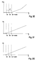
Das Verfahren wird ausgeführt, um zumindest bei einem Bremsbetätigungsweg s ungleich Null aber unter einem Mindestbremsweg smin, unter welchem eine Kraftübertragung zwischen dem Bremsbetätigungselement und dem Hauptbremszylinder (zumindest signifikant) unterbunden ist, eine Batterie mittels des Generators aufzuladen. Sofern ein Kann-Generator-Bremsmoment bgen0 ungleich Null ausführbar ist (siehe
Zusätzlich wird das als Trennventil verwendete zweite Ventil bei einem Bremsbetätigungsweg s kleiner als einem ersten Grenzweg s1 ebenfalls in einen zumindest teilgeöffneten Zustand gesteuert. Vorzugsweise ist das zweite Ventil als stromlos geöffnetes Ventil ausgebildet. In diesem Fall kann eine zweite Stromstärke I2 gleich Null zum vorteilhaften Ansteuern des zweiten Ventils an dieses bereitgestellt werden.In addition, the second valve used as a separating valve is also controlled in an at least partially opened state at a Bremsbetätigungsweg s smaller than a first Grenzweg s1. Preferably, the second valve is designed as a normally open valve. In this case, a second current I2 equal to zero may be provided for advantageously driving the second valve thereto.
Aufgrund der vorteilhaften Ansteuerung der beiden Ventile mittels der Stromstärken I1 und I2 verschiebt der Bremskraftverstärker während der Betätigung des Bremsbetätigungselements mit einem Bremsbetätigungsweg s kleiner als einem ersten Grenzweg s1 ein Bremsflüssigkeitsvolumen aus der mit dem zweiten Ventil verbundenen zweiten Druckkammer des Hauptbremszylinders über die angesteuerten Ventile in das Bremsmediumreservoir. Da das Losbrech-Moment der Radbremszylinder des abtrennbaren zweiten Bremskreises höher als der Druck in dem Bremsmediumreservoir ist, welcher in der Regel gleich dem Atmosphärendruck ist, wird keine Bremsflüssigkeit in die Radbremszylinder des zweiten Bremskreises verschoben. Somit ist es nicht notwendig, die Radeinlassventile des zweiten Bremskreises zu schließen. Bevorzugter Weise sind die Radeinlassventile des zweiten Bremskreises als stromlos offene Ventile ausgebildet. In diesem Fall kann bei einem Bremsbetätigungsweg s kleiner als einem ersten Grenzweg s1 eine Radeinlassventil-Stromstärke Irev gleich Null an diese bereitgestellt werden, wie in
Über die oben schon beschriebene vorteilhafte Ausbildung des Hauptbremszylinders ist gleichzeitig gewährleistbar, dass der Schwimmkolben bei einem Bremsbetätigungsweg s unter dem ersten Grenzweg s1 so verstellt wird, dass in der mit dem nicht-entkoppelbaren ersten Bremskreis hydraulisch verbundenen ersten Druckkammer des Hauptbremszylinders kein Druck aufgebaut wird. Dazu wird der Schwimmkolben in Richtung der zweiten Druckkammer verschoben. Somit ist bewirkbar, dass in die der ersten Druckkammer des Hauptbremszylinders zugeordneten Radbremszylinder des ersten Bremskreises kein Bremsflüssigkeitsvolumen verschoben wird.About the above-described advantageous embodiment of the master cylinder is simultaneously gewährleistbar that the floating piston at a Bremsbetätigungsweg s below the first limit s1 is adjusted so that in the non-decoupled first brake circuit hydraulically connected to the first pressure chamber of the master cylinder no pressure is built up. For this purpose, the floating piston is moved in the direction of the second pressure chamber. Thus, it can be effected that no brake fluid volume is displaced into the wheel brake cylinder of the first brake circuit assigned to the first pressure chamber of the master brake cylinder.
Bei einem Bremsbetätigungsweg s zwischen Null und dem ersten Grenzweg s1 sind das Bremsmoment b1 der Radbremszylinder des ersten Bremskreises (des nicht-abtrennbaren/nicht-entkoppelbaren Bremskreises) und das Bremsmoment b2 der Radbremszylinder des zweiten Bremskreises (des abtrennbaren/entkoppelbaren Bremskreises) trotz geöffneter Radeinlassventile auf Werte gleich Null einstellbar, wie in
Das vom Fahrer angeforderte Soll-Gesamtbremsmoment bsoll wird in diesem Fall zu 100% als Generator-Bremsmoment bgen aufgebracht. Beispielsweise kann der Generator das Generator-Bremsmoment bgen an einer dem nicht-abtrennbaren ersten Bremskreis zugeordneten Achse, wie insbesondere der Vorderachse, aufbringen.The requested by the driver target total braking torque bsoll is applied in this case to 100% as generator braking torque bgen. For example, the generator may apply the generator braking torque to an axle assigned to the non-detachable first brake circuit, such as, in particular, the front axle.
Ab dem ersten Grenzweg s1 nähert sich der Bremsbetätigungsweg s bei zeitlicher Zunahme dem Mindestbremsweg smin. In dieser Situation kann das Bremssystem auf ein baldiges Verlassen des Jump-In-Bereichs vorbereitet werden. Damit das Verlassen des Jump-In-Bereichs für den Fahrer mit einem standardgemäßen Pedalgefühl verbunden ist, wird der Bremsdruck in dem nicht-abtrennbaren ersten Bremskreis auf einem dem Mindestbremsweg smin entsprechenden Wert eingestellt. Für ein weiteres Betreiben des Generators zum Aufladen der Batterie kann das zweite hydraulische Bremsmoment b2 des abtrennbaren zweiten Bremskreises gleichzeitig gleich Null gehalten werden. Dazu werden die Radeinlassventile des zweiten Bremskreises geschlossen. Dies kann durch ein Bereitstellen einer Radeinlassventil-Stromstärke Irev ungleich Null erfolgen.From the first limit travel s1, the brake actuation travel s approaches the minimum brake travel smin with an increase in time. In this situation, the braking system can be prepared for leaving the jump-in area soon. In order for the driver to leave the jump-in area with a standard pedal feel, the brake pressure in the non-disconnectable first brake circuit is set to a value corresponding to the minimum braking distance smin. For a further operation of the generator for charging the battery, the second hydraulic braking torque b2 of the separable second brake circuit can be kept equal to zero at the same time. For this purpose, the Radeinlassventile the second brake circuit are closed. This can be done by providing a wheel inlet valve current Irev not equal to zero.
Zum Einstellen eines gewünschten Bremsdrucks in dem nicht-abtrennbaren ersten Bremskreis wird die zweite Pumpe des zweiten Bremskreises mit einem Pump-Versorgungsstrom Ip ungleich Null angesteuert. Bei einem geöffneten zweiten Ventil wird auf diese Weise mittels der zweiten Pumpe ein Bremsflüssigkeitsvolumen aus dem Bremsmediumreservoir über die Saugleitung und das geöffnete zweite Ventil in die zweite Druckkammer des Hauptbremszylinders gefördert. Mittels des ersten Ventils, d. h. mittels einer variierenden ersten Stromstärke I1, kann der Druck in der zweiten Druckkammer des Hauptbremszylinders so eingestellt werden, dass mittels einer Verschiebung des Schwimmkolbens teilweise aus der zweiten Druckkammer hinein in die erste Druckkammer der gewünschte Druck in der ersten Druckkammer vorliegt. Mittels des ersten Ventils wird somit der Bremsdruck in dem nicht-entkoppelbaren ersten Bremskreis so eingestellt, dass das gewünschte hydraulische Bremsmoment b1 ungleich Null der Radbremszylinder des ersten Bremskreises vorliegt. Ziel dieser Ansteuerung ist es, beim Erreichen des Jump-Ins (der Grenze des Jump-In-Bereichs) ein dem gewünschten ersten hydraulischen Bremsmoment b1 entsprechendes Bremsflüssigkeitsvolumen in den ersten Bremskreis zu fördern. Es wird noch einmal darauf hingewiesen, dass dieses Volumen aus dem Bremsmediumreservoir angesaugt wird und über das offene zweite Ventil in die zweite Druckkammer des Hauptbremszylinders gefördert wird.To set a desired brake pressure in the non-disconnectable first brake circuit, the second pump of the second brake circuit is driven with a pump supply current Ip not equal to zero. With an opened second valve, a brake fluid volume from the brake medium reservoir via the suction line and the opened second valve in the second pressure chamber of the master cylinder is promoted in this way by means of the second pump. By means of the first valve, ie by means of a varying first current I1, the pressure in the second pressure chamber of the master cylinder can be adjusted so that by means of a displacement of the floating piston partially from the second pressure chamber into the first pressure chamber, the desired pressure in the first pressure chamber , By means of the first valve thus the brake pressure in the non-decoupled first brake circuit is set so that the desired hydraulic braking torque b1 is not equal to zero of the wheel brake cylinder of the first brake circuit. The aim of this control is to promote a brake fluid volume corresponding to the desired first hydraulic braking torque b1 when reaching the jump-ins (the limit of the jump-in range) into the first brake circuit. It is pointed out again that this volume is sucked from the brake medium reservoir and is conveyed via the open second valve in the second pressure chamber of the master cylinder.
Während das erste hydraulische Bremsmoment b1 ab dem ersten Grenzweg s1 zunimmt, erfolgt kein Druckaufbau in den Radbremszylindern des abtrennbaren zweiten Bremskreises aufgrund der geschlossenen Radeinlassventile des zweiten Bremskreises. Das zweite hydraulische Bremsmoment b2 der Radbremszylinder des zweiten Bremskreises bleibt somit gleich Null (siehe
Gleichzeitig kann das Generator-Bremsmoment bgen entsprechend der zeitlichen Zunahme des ersten hydraulischen Bremsmoments b1 zurückgenommen/zurückgefahren werden. Somit ist auch bei einem Bremsbetätigungsweg s zwischen dem ersten Bremsbetätigungsweg s1 und dem Mindestbremsweg smin ein dem Bremsbetätigungsweg s entsprechendes Soll-Gesamtbremsmoment bsoll einhaltbar.At the same time, the generator braking torque bgen can be reduced / reduced in accordance with the time increase of the first hydraulic braking torque b1. Thus, even with a Bremsbetätigungsweg s between the first Bremsbetätigungsweg s1 and the Mindestbremsweg smin a brake operation path s corresponding target total braking torque bsoll is maintainable.
Ab einem Bremsbetätigungsweg s gleich dem Mindestbremsweg smin wird das zweite Ventil mittels eines Versorgungsstroms mit einer zweiten Stromstärke I2 ungleich Null geschlossen. Der zweite Bremskreis ist somit ab einem Bremsbetätigungsweg s gleich dem Mindestbremsweg smin von dem Hauptbremszylinder hydraulisch abgetrennt/entkoppelt. Man kann dies auch so umschreiben, dass das Bremssystem sich nun im Brake-by-wire-Modus befindet. Der Fahrer hat jedoch bei einer zeitlichen Zunahme des Bremsbetätigungswegs s weiterhin die Möglichkeit, direkt in den ersten Bremskreis einzubremsen und auf diese Weise das erste hydraulische Bremsmoment b1 zu steigern. Auch das Generator-Bremsmoment bgen kann entsprechend einem gewünschten Soll-Gesamtbremsmoment bsoll gesteigert werden, sofern das Kann-Generator-Bremsmoment bgen0 dies zulässt. Somit kann auch außerhalb des Jump-In-Bereichs regenerativ gebremst und verblendet werden. Dies kann in einer Strategie entsprechend der installierten Bremskraftverteilung erfolgen. Alternativ sind natürlich auch andere Strategien der Bremskraftverteilung denkbar, z. B. eine theoretische Überbremsung der Achse des entkoppelbaren zweiten Bremskreises zur Erhöhung der rekuperativen Effizienz.From a Bremsbetätigungsweg s equal to the Mindestbremsweg smin the second valve is closed by means of a supply current with a second current I2 not equal to zero. The second brake circuit is thus separated from a Bremsbetätigungsweg s equal to the Mindestbremsweg smin of the master cylinder hydraulically / decoupled. You can also rewrite this so that the brake system is now in brake-by-wire mode. However, with a time increase of the brake actuation travel s, the driver still has the option of braking directly into the first brake circuit and thus of increasing the first hydraulic brake torque b1. Also, the generator braking torque bgen can be increased according to a desired target total braking torque bsoll, if the can-generator braking torque bgen0 allows this. Thus, outside the jump-in area can be regeneratively braked and blinded. This can be done in a strategy according to the installed brake force distribution. Alternatively, of course, other strategies of braking force distribution are conceivable, for. B. a theoretical overbraking the axis of the decoupled second brake circuit to increase the recuperative efficiency.
Das zweite hydraulische Bremsmoment b2 des zweiten Bremskreises kann konstant gleich Null gehalten werden. Dazu können das erste Ventil geschlossen und die Radeinlassventile geöffnet werden, indem Stromstärken I1 und Irev gleich Null an diese bereitgestellt werden. Da eine Funktion der zweiten Pumpe in diesem Systemzustand nicht erforderlich ist, kann die Pump-Stromstärke Ip ebenfalls gleich Null eingestellt werden.The second hydraulic braking torque b2 of the second brake circuit can be kept constant at zero. For this purpose, the first valve can be closed and the Radeinlassventile be opened by current levels I1 and Irev equal to zero are provided to this. Since a function of the second pump is not required in this system state, the pump current Ip can also be set equal to zero.
Während des dargestellten Verfahrens bremst der Fahrer mit einem (konstanten) Bremsbetätigungsweg s größer als dem Mindestbremsweg smin. Das Verfahren der
Bis zu einer Zeit t2 ist das ausführbare Kann-Generator-Bremsmoment bgen0 größer als das ausgeführte Generator-Bremsmoment bgen. Somit können zwischen den Zeiten t0 bis t2 die am Ende des Verfahrens der zuvor beschriebenen Figuren eingestellten Werte für das Soll-Gesamtbremsmoment bsoll, das Generator-Bremsmoment bgen, das erste hydraulische Bremsmoment b1, das zweite hydraulische Bremsmoment b2, die erste Stromstärke I1, die zweite Stromstärke I2, die Radeinlassventil-Stromstärke Irev und die Pump-Stromstärke Ip beibehalten werden.Until a time t2, the executable on-generator braking torque bgen0 is greater than the executed generator braking torque bgen. Thus, between the times t0 to t2, the set values for the target total braking torque bsetpoint, the generator braking torque bgen, the first hydraulic braking torque b1, the second hydraulic braking torque b2, the first current intensity I1, the set values at the end of the method of the previously described figures second current intensity I2, the Radeinlassventil current Irev and the pump current Ip are maintained.
Ab der Zeit t1 nimmt das Kann-Generator-Bremsmoments bgen0 zeitlich ab. Die zeitliche Abnahme des Kann-Generator-Bremsmoments bgen0 kann beispielsweise darauf zurückzuführen sein, dass das Fahrzeug nur noch eine geringe Geschwindigkeit hat und/oder die aufladbare Batterie bereits fast vollständig aufgeladen ist. Beide Faktoren erlauben lediglich ein begrenztes Generator-Bremsmoment bgen.From time t1, the can-generator braking torque bgen0 decreases in time. The time decrease of the can-generator braking torque bgen0 can be due, for example, to the fact that the vehicle only has a low speed and / or the rechargeable battery is already almost completely charged. Both factors allow only a limited generator braking torque bgen.
Von der Zeit t0 an ist das zuvor eingestellte Generator-Bremsmoment bgen aufgrund der zeitlichen Abnahme des Kann-Generator-Bremsmoments bgen0 nicht mehr ausführbar. Das dem (konstanten) Bremsbetätigungsweg s entsprechende Soll-Gesamtbremsmoment bsoll ist jedoch trotz der starken zeitlichen Abnahme des Generator-Bremsmoments bgen verlässlich einhaltbar. Dazu kann über einen hydraulischen Druckaufbau in dem entkoppelbaren zweiten Bremskreis das zweite hydraulische Bremsmoment b2 gesteigert werden. Die zeitliche Abnahme des Kann-Generator-Bremsmoments ist somit für den Fahrer nicht mit einer Komforteinbuße verbunden.From the time t0 to the previously set generator braking torque bgen is no longer executable due to the time decrease of the can-generator braking torque bgen0. However, the setpoint total braking torque bsoll corresponding to the (constant) brake actuation travel s is reliably maintainable despite the strong time decrease of the generator braking torque bgen. For this purpose, the second hydraulic braking torque b2 can be increased via a hydraulic pressure build-up in the decoupled second brake circuit. The time reduction of the can-generator braking torque is thus not associated with a loss of comfort for the driver.
Der Druckaufbau in dem zweiten Bremskreis ist über ein Ansteuern der zweiten Pumpe mit einer Pump-Stromstärke Ip ungleich Null ausführbar. Während des Druckaufbaus bleiben das erste Ventil und das zweite Ventil geschlossen und die Radeinlassventile des entkoppelbaren zweiten Bremskreises geöffnet. Dazu werden eine erste Stromstärke I1 gleich Null an das erste Ventil, eine zweite Stromstärke I2 ungleich Null an das zweite Ventil und eine Radeinlassventil-Stromstärke Irev gleich Null an die Radeinlassventile bereitgestellt.The pressure build-up in the second brake circuit is executable by driving the second pump with a pump current Ip not equal to zero. During pressure build-up, the first valve and the second valve remain closed and the Radeinlassventile the decoupled second brake circuit open. For this purpose, a first current I1 equal to zero to the first valve, a second current I2 not equal to zero to the second valve and a Radeinlassventil current Irev equal to zero provided to the Radeinlassventile.
Idealerweise erfolgt der Druckaufbau in dem zweiten Bremskreis entsprechend der installierten Bremskraftverteilung, da dann identische Verhältnisse zum Standardsystem vorherrschen. Andere Strategien sind jedoch ebenfalls denkbar, z. B. kann eine Überbremsung der Achse des zweiten Bremskreises zum Steigern der rekuperativen Effizienz vorgesehen sein.Ideally, the pressure build-up in the second brake circuit is carried out according to the installed brake force distribution, since then identical conditions prevail to the standard system. Other strategies are also conceivable, for. B. can be provided to increase the recuperative efficiency overbraking the axis of the second brake circuit.
Bei dem anhand der
Mit der zeitlichen Abnahme des Bremsbetätigungswegs s wird auch ein zeitlich abnehmendes Soll-Gesamtbremsmoment bsoll festgelegt. Aufgrund des abnehmenden Bremsbetätigungsweges s nimmt auch das erste hydraulische Bremsmoment b1 des nicht-entkoppelbaren ersten Bremskreises, in welchem der Fahrer direkt einbremst, zeitlich ab. Gleichzeitig kann der Generator so angesteuert werden, dass mittels einer zeitlichen Abnahme des Generator-Bremsmoments bgen das gewünschte Soll-Gesamtbremsmoment bsoll verlässlich eingehalten wird. Gleichzeitig kann das zweite hydraulische Bremsmoment b2 der Radbremszylinder des zweiten Bremskreises, welcher von dem Hauptbremszylinder hydraulisch abgetrennt/entkoppelt ist, einen Wert von Null aufweisen. Das erste Ventil und das zweite Ventil können aufgrund einer ersten Stromstärke I1 gleich Null und einer zweiten Stromstärke 12 ungleich Null im geschlossenen Zustand vorliegen. Die Radeinlassventile des entkoppelbaren zweiten Bremskreises können mittels einer Radeinlassventil-Stromstärke Irev gleich Null in den geöffneten Zustand gesteuert sein. Da eine Funktion der zweiten Pumpe des entkoppelbaren zweiten Bremskreises bei einem zeitlich abnehmenden Bremsbetätigungsweg s zwischen dem Ausgangsbremsweg saus und einem zweiten Grenzweg s2 nicht nötig ist, kann die Pump-Stromstärke Ip in diesem Fall gleich Null sein.With the time reduction of the brake actuation path s, a time-decreasing setpoint total braking torque bsoll is also defined. Due to the decreasing brake actuation travel s, the first hydraulic brake torque b1 of the non-decoupled first brake circuit, in which the driver brakes directly, also decreases in time. At the same time, the generator can be controlled so that by means of a temporal decrease of the generator braking torque bgen the desired desired total braking torque bsoll is reliably maintained. At the same time, the second hydraulic braking torque b2 of the wheel brake cylinders of the second brake circuit, which is hydraulically disconnected / decoupled from the master brake cylinder, can have a value of zero. The first valve and the second valve may be zero due to a first current I1 and a second current 12 not equal to zero in the closed state. The Radeinlassventile the decoupled second brake circuit can be controlled by means of a Radeinlassventil current Irev equal to zero in the open state. Since a function of the second pump of the decoupled second brake circuit at a time-decreasing Bremsbetätigungsweg s between the Ausgangsbremsweg saus and a second Grenzweg s2 is not necessary, the pump current Ip may be equal to zero in this case.
Ab einem Bremsbetätigungsweg s gleich dem zweiten Grenzweg s2, welcher vorzugsweise gleich dem Mindestbremsweg smin ist, wird das Generator-Bremsmoment bgen auf einen Wert entsprechend des (theoretischen) Bremsmoments des entkoppelbaren zweiten Bremskreises eingestellt. Auf diese Weise ist sicherstellbar, dass trotz einer Verblendung immer wieder auf die vordefinierte hydraulische Bremskraftverteilung zurückgefahren werden kann.From a Bremsbetätigungsweg s equal to the second limit s2, which is preferably equal to the Mindestbremsweg smin, the generator braking torque bgen is set to a value corresponding to the (theoretical) braking torque of the decoupled second brake circuit. In this way, it is possible to ensure that, in spite of a veneer, it is always possible to go back to the predefined hydraulic braking force distribution.
Während der Zunahme des Generator-Bremsmoments bgen wird das erste hydraulische Bremsmoment b1 des nicht-entkoppelbaren ersten Bremskreises reduziert. Dies erfolgt über eine Volumenverschiebung aus dem Hauptbremszylinder über den entkoppelbaren zweiten Bremskreis in das Bremsmediumreservoir. Dazu wird das zweite Ventil mittels einer zweiten Stromstärke 12 gleich Null geöffnet. Mittels eines Ansteuerns des ersten Ventils mit einer variierenden Stromstärke I1 ungleich Null kann ein Bremsflüssigkeitsvolumen aus der zweiten Druckkammer des Hauptbremszylinders über das geöffnete zweite Ventil und das zumindest teilgeöffnete erste Ventil in das Bremsmediumreservoir verschoben werden. Dabei verstellt sich auch der Schwimmkolben von der ersten Druckkammer weg in Richtung der zweiten Druckkammer des Hauptbremszylinders. Die auf diese Weise bewirkte Vergrößerung der ersten Druckkammer führt zu einem Druckabbau in dem nicht-entkoppelbaren ersten Bremskreis und damit zu einer Reduzierung des ersten hydraulischen Bremsmoments b1 der Radbremszylinder des ersten Bremskreises.During the increase of the generator braking torque bgen, the first hydraulic braking torque b1 of the non-decoupled first brake circuit is reduced. This is done via a volume shift from the master cylinder via the decoupled second brake circuit in the brake fluid reservoir. For this purpose, the second valve is opened by means of a second current 12 equal to zero. By means of a control of the first valve with a varying current intensity I1 not equal to zero, a brake fluid volume can be displaced from the second pressure chamber of the master brake cylinder via the opened second valve and the at least partially opened first valve into the brake medium reservoir. In this case, the floating piston also moves away from the first pressure chamber in the direction of the second pressure chamber of the master cylinder. The enlargement of the first pressure chamber effected in this way leads to a pressure reduction in the non-decoupled first brake circuit and thus to a reduction of the first hydraulic braking torque b1 of the wheel brake cylinder of the first brake circuit.
Während der in dem vorausgehenden Absatz beschriebenen Vorgehensweise können die Radeinlassventile des zweiten Bremskreises mittels einer Radeinlassventil-Stromstärke Irev ungleich Null geschlossen werden, um das zweite hydraulische Bremsmoments b2 der Radbremszylinder des zweiten Bremskreises trotz der Verschiebung des Bremsflüssigkeitsvolumens gleich Null zu halten. Da ein Einsatz der zweiten Pumpe des entkoppelbaren zweiten Bremskreises zum Verschieben des Bremsflüssigkeitsvolumens nicht nötig ist, kann die Pump-Stromstärke Ip gleich Null bleiben.During the procedure described in the preceding paragraph, the Radeinlassventile the second brake circuit can be closed by means of a Radeinlassventil Stromstärke Irev not equal to zero to keep the second hydraulic braking torque b2 of the wheel brake cylinder of the second brake circuit despite the displacement of the brake fluid volume zero. Since it is not necessary to use the second pump of the decoupled second brake circuit to displace the brake fluid volume, the pump current Ip can remain zero.
Ab einem Bremsbetätigungsweg s3, welcher insbesondere kleiner als der Mindestbremsweg s sein kann, liegt ein erstes hydraulisches Bremsmoment b1 gleich Null vor. Entsprechend der weiteren zeitlichen Abnahme des Bremsbetätigungswegs s kann ein zeitlich reduziertes Soll-Gesamtbremsmoment bsoll festgelegt werden, welches, sofern das Kann-Generator-Bremsmoment bgen0 dies zulässt, lediglich durch ein Generator-Bremsmoment bgen gleich dem Soll-Gesamtbremsmoment bsoll aufgebracht wird. Somit ist ein vorteilhaft schnelles Aufladen der aufladbaren Batterie auch bei einer Bremsbetätigung mit einem vergleichsweise geringen, zeitlich abnehmenden Bremsbetätigungsweg s gewährleistbar.From a Bremsbetätigungsweg s3, which may be in particular smaller than the Mindestbremsweg s, a first hydraulic braking torque b1 is equal to zero. Corresponding to the further time decrease of the brake actuation travel s, a time-reduced nominal total braking torque bsoll can be set, which, if the can-generator braking torque bgen0 permits, is merely applied by a generator braking torque bgen equal to the desired total braking torque bsoll. Thus, an advantageously fast charging of the rechargeable battery is guaranteed even with a brake operation with a comparatively small, time-decreasing Bremsbetätigungsweg s.
Die hydraulischen Bremsmomente b1 und b2 können gleich Null gehalten werden. Die mit der zeitlichen Abnahme des Bremsbetätigungswegs s verbundene Vergrößerung der zweiten Druckkammer kann über ein Ansaugen eines Bremsflüssigkeitsvolumens aus dem Bremsmediumreservoir ausgeglichen werden, ohne dass sich ein Bremsdruck in den Radbremszylindern des entkoppelbaren zweiten Bremskreises aufbaut. Die Radeinlassventile des entkoppelbaren zweiten Bremskreises können dabei auch geöffnet vorliegen. Das erste Ventil kann mittels eines Versorgungsstroms mit einer maximalen ersten Stromstärke I1 zum Ansaugen des Bremsflüssigkeitsvolumens vollständig geöffnet werden.The hydraulic braking torques b1 and b2 can be kept equal to zero. The increase in the second pressure chamber associated with the time reduction of the brake actuation travel s can be compensated for by aspirating a brake fluid volume from the brake fluid reservoir, without a brake pressure building up in the wheel brake cylinders of the decoupled second brake circuit. The Radeinlassventile the decoupled second brake circuit can also be open. The first valve can be fully opened by means of a supply current with a maximum first current I1 for sucking the brake fluid volume.
Man kann die anhand der
Die vorausgehend beschriebenen Verfahren sind auch bei einem Fahrzeug mit einem Generator an der Hinterachse, an der entkoppelbaren Achse oder bei einem Fahrzeug, bei welchem der Generator auf alle vier Räder wirkt, anwendbar. Insbesondere bei einer Ausstattung des Fahrzeugs mit einem Generator an der entkoppelbaren Achse lassen sich auch die Strategie eines "Überbremsens der entkoppelbaren Achse", insbesondere der Hinterachse, anwenden, was zu einer Erhöhung der rekuperativen Effizienz beiträgt. Durch eine entsprechende Schaltung der Einlassventile kann der hydraulische Druckaufbau zum Verblenden an der Vorderachse, an der Hinterachse, aber auch an allen Achsen gleichzeitig durchgeführt werden.The methods described above are also applicable to a vehicle having a generator on the rear axle, on the decoupled axle or in a vehicle in which the generator acts on all four wheels. In particular, when equipping the vehicle with a generator on the decoupled axle, the strategy of "overbraking the decoupled axle", in particular the rear axle, can also be applied, which contributes to an increase in recuperative efficiency. By a corresponding circuit of the intake valves, the hydraulic pressure build-up for veneering on the front axle, on the rear axle, but also on all axles can be performed simultaneously.
Claims (8)
- Control device (100) for a brake system of a vehicle, having
a valve control apparatus (10) which is configured to define a first setpoint state of a first valve (88) of the brake system, at least taking into account a supplied information signal (12) with respect to a generator braking torque (bgen) of a generator which is currently applied or is to be applied, which first valve (88) is connected to a master brake cylinder (62) of the brake system and to a fluid storage device of the brake system in such a way that a brake fluid volume can be displaced from the master brake cylinder (62) into the fluid storage device via the first valve (88) which is controlled into an at least partially opened state, and to output a first control signal (14, 12), corresponding to the first setpoint state, to the first valve (88);
wherein, the first setpoint state for a valve (88) connected via at least one suction line (89) to a braking medium reservoir (61) of the brake system as a fluid storage device can be defined as the first valve (88) by means of the valve control apparatus (10); and
wherein the valve control apparatus (10) is additionally configured to define a second setpoint state of a second valve (86) of the brake system, taking into account a first sensor signal (16a) relating to an activation intensity (s) of activation of a brake actuation element (64) of the brake system, of the information signal (12) and/or of the first setpoint state, which second valve (86) is arranged as an isolating valve (86) between the master brake cylinder (62) and a brake circuit (52) of the brake system with the first valve (88) and at least one wheel brake cylinder (54b), and to output a second control signal (18, 12) corresponding to the second setpoint state to the second valve (86);
characterized in that
the valve control apparatus (10) is additionally configured to compare the first sensor signal (16a) with a predefined comparison signal relating to a minimum activation intensity (smin) starting from which a driver braking force (Fb), applied to the brake activation element (64), can be transmitted to an adjustable master brake cylinder piston (63) of the master brake cylinder (62), and, insofar as the first sensor signal (16a) is below the comparison signal, to control the second valve (86) into an at least partially open state in such a way that a brake fluid volume which is forced out of the master brake cylinder (62) can be displaced into the brake circuit (52) via the second valve (86) which is controlled into the at least partially opened state, or, insofar as the first sensor signal (16a) exceeds the comparison signal, to control the second valve (86) into a closed state in such a way that a hydraulic connection between the master brake cylinder (62) and the brake circuit (52) is prevented. - Control device (100) according to Claim 1, wherein the control device (100) comprises a pump control apparatus (20) which is configured, insofar as the first sensor signal (16a) approaches the comparison signal when the activation intensity (s) increases over time, to output a pump control signal (22) to a pump (90) of the brake system, by means of which signal (22) the pump (90) can be actuated to pump a brake fluid volume from the braking medium reservoir (61) into the master brake cylinder (62) via the second valve (86) which is in the at least partially opened state.
- Control device (100) according to Claim 1 or 2, wherein the control device (100) comprises a generator control apparatus (24) by means of which the generator braking torque (bgen) of the generator which is to be applied can be defined taking into account the first sensor signal (16a) and/or a second sensor signal and/or information signal (16b) relating to at least one executable possible generator braking torque (bgenO), and a generator control signal (26), corresponding to the defined generator braking torque (bgen) which is to be applied, can be output to the generator.
- Brake system for a vehicle having a control device (100) according to one of the preceding claims.
- Method for operating a brake system of a vehicle having the steps:defining a first setpoint state of a first valve (88) of the brake system, which valve (88) is connected to a master brake cylinder (62) of the brake system and to a fluid storage device of the brake system in such a way that a brake fluid volume can be displaced from the master brake cylinder (62) into the fluid storage device via the first valve (88) which is controlled into an at least partially opened state, taking into account a generator braking torque variable relating to a generator braking torque (bgen) of a generator which is currently applied or is to be applied, wherein the first setpoint state for a valve (88) which is connected via at least one suction line (89) to a braking medium reservoir (61) of the brake system as a fluid storage device is defined (S1) as a first valve (88); andactuating the first valve (88) taking into account the defined first setpoint state (S2);wherein a second setpoint state of a second valve (86) of the brake system is defined (S3) taking into account an actuation intensity variable relating to an activation intensity (s) of an activation of a brake activation element (64) of the brake system, the generator braking torque variable and/or the first setpoint state, which valve (86) is arranged as an isolating valve (86) between the master brake cylinder (62) and a brake circuit (52) of the brake system with the first valve (88) and at least one wheel brake cylinder (54b), and the second valve (86) is actuated (S4) taking into account the defined second setpoint state;
characterized in that
the actuation intensity variable is compared with a minimum activation intensity variable relating to a minimum activation intensity (smin) starting from which a driver braking force (Fb), which is applied to a brake activation element (64), is transmitted to an adjustable master brake cylinder piston (63) of the master brake cylinder (62), and, insofar as the activation intensity variable is below the minimum activation intensity variable, the second valve (86) is controlled into an at least partially opened state in such a way that a brake fluid volume which is forced out of the master brake cylinder (62) is displaced into the brake circuit (52) via the second valve (86) which is controlled into the at least partially opened state, or, insofar as the activation intensity variable exceeds the minimum activation intensity variable, the second valve (86) is controlled into a closed state in such a way that a hydraulic connection between the master brake cylinder (62) and the brake circuit (52) is prevented. - Method according to Claim 5, wherein the generator braking torque variable is compared with a predefined minimum braking torque variable, and, insofar as the generator braking torque variable is above the minimum braking torque variable, the first valve (88) is controlled into the at least partially opened state in such a way that a brake fluid volume which is forced out of the master brake cylinder (62) is displaced into the braking medium reservoir (61) via the first valve (88) which is controlled into the at least partially opened state, or, insofar as the generator braking torque variable is below the minimum braking torque variable, the first valve (88) is controlled into a closed state in such a way that a hydraulic connection between the master brake cylinder (62) and the braking medium reservoir (61) is prevented.
- Method according to Claim 5 or 6, wherein, insofar as the activation intensity variable tends towards the minimum activation intensity variable when the activation intensity variable increases over time, a braking fluid volume is pumped (S5), by means of a pump (90) of the brake system, out of the braking medium reservoir (61) into the master brake cylinder (62) via the second valve (86) which is in the at least partially opened state.
- Method according to one of claims 5 to 7, wherein, insofar as the activation intensity variable tends towards the minimum activation intensity variable when the activation intensity variable decreases over time, the second valve (86) is controlled into the at least partially opened state in such a way that a braking fluid volume is transferred (S6) from the braking medium reservoir (61) into the master brake cylinder (62) via the second valve (86) which is in the at least partially opened state.
Applications Claiming Priority (2)
| Application Number | Priority Date | Filing Date | Title |
|---|---|---|---|
| DE102011075968A DE102011075968A1 (en) | 2011-05-17 | 2011-05-17 | Control device for a brake system of a vehicle and method for operating a brake system of a vehicle |
| PCT/EP2012/054790 WO2012156125A1 (en) | 2011-05-17 | 2012-03-19 | Control device for a vehicle brake system, and method for operating a vehicle brake system |
Publications (2)
| Publication Number | Publication Date |
|---|---|
| EP2709882A1 EP2709882A1 (en) | 2014-03-26 |
| EP2709882B1 true EP2709882B1 (en) | 2016-11-16 |
Family
ID=45894453
Family Applications (1)
| Application Number | Title | Priority Date | Filing Date |
|---|---|---|---|
| EP12710913.0A Active EP2709882B1 (en) | 2011-05-17 | 2012-03-19 | Control device for a vehicle brake system, and method for operating a vehicle brake system |
Country Status (7)
| Country | Link |
|---|---|
| US (1) | US9421953B2 (en) |
| EP (1) | EP2709882B1 (en) |
| JP (1) | JP5863954B2 (en) |
| KR (1) | KR101948950B1 (en) |
| CN (1) | CN103562025B (en) |
| DE (1) | DE102011075968A1 (en) |
| WO (1) | WO2012156125A1 (en) |
Families Citing this family (18)
| Publication number | Priority date | Publication date | Assignee | Title |
|---|---|---|---|---|
| DE102012222978A1 (en) * | 2012-12-12 | 2014-06-12 | Robert Bosch Gmbh | Method for operating a brake system of a vehicle and control device for a brake system of a vehicle |
| US9033426B2 (en) * | 2012-12-19 | 2015-05-19 | Robert Bosch Gmbh | Braking system with switchable pump path |
| DE102013200465A1 (en) * | 2013-01-15 | 2014-07-17 | Robert Bosch Gmbh | Hydraulic brake system aggregate, hydraulic braking system, control device for interacting with a hydraulic braking system, and method of operating a hydraulic braking system |
| DE102013200471A1 (en) * | 2013-01-15 | 2014-07-17 | Robert Bosch Gmbh | Hydraulic brake system aggregate, hydraulic braking system, control device for interacting with a hydraulic braking system, and method of operating a hydraulic braking system |
| DE102013200604A1 (en) | 2013-01-16 | 2014-07-17 | Robert Bosch Gmbh | Method and device for operating a brake system |
| DE102013206324A1 (en) * | 2013-04-10 | 2014-10-16 | Robert Bosch Gmbh | Brake system for a vehicle and method for operating the brake system |
| DE102014205645A1 (en) * | 2013-04-24 | 2014-10-30 | Robert Bosch Gmbh | Method for operating a brake system for a vehicle and control device for a brake system of a vehicle |
| DE102013208703A1 (en) | 2013-05-13 | 2014-11-13 | Robert Bosch Gmbh | Control device for a recuperative braking system of a vehicle and method for braking a vehicle |
| DE102013209175A1 (en) | 2013-05-17 | 2014-11-20 | Robert Bosch Gmbh | Method for braking a vehicle and control device for a recuperative braking system of a vehicle |
| JP6237139B2 (en) * | 2013-11-12 | 2017-11-29 | 日産自動車株式会社 | Brake control device for vehicle |
| DE102015212552A1 (en) * | 2014-07-21 | 2016-01-21 | Continental Teves Ag & Co. Ohg | Arrangement for a hydraulic motor vehicle brake system and brake system with such an arrangement |
| DE102014222753A1 (en) | 2014-11-07 | 2016-05-12 | Robert Bosch Gmbh | A brake system for a vehicle, method for operating a brake system of a vehicle, and method of manufacturing a brake system for a vehicle |
| DE102016205406A1 (en) * | 2016-04-01 | 2017-10-05 | Robert Bosch Gmbh | Method and control device for operating a brake system of a vehicle equipped with an electrohydraulic brake booster device |
| DE102016208529A1 (en) | 2016-05-18 | 2017-11-23 | Robert Bosch Gmbh | A braking system for a vehicle and method for operating a braking system of a vehicle |
| DE102016209781A1 (en) * | 2016-06-03 | 2017-12-07 | Robert Bosch Gmbh | Method for operating a hydraulic brake system, hydraulic brake system |
| DE102019113757A1 (en) * | 2019-05-23 | 2020-11-26 | Zf Active Safety Gmbh | Method for controlling a hydraulic brake system during a regenerative braking process, hydraulic brake system, computer program product, control unit and motor vehicle |
| WO2020246868A1 (en) * | 2019-06-07 | 2020-12-10 | 주식회사 만도 | Structure of control device in brake system |
| CN114572177B (en) * | 2020-12-02 | 2023-05-23 | 宇通客车股份有限公司 | Brake valve, new energy vehicle using brake valve and brake control method |
Family Cites Families (21)
| Publication number | Priority date | Publication date | Assignee | Title |
|---|---|---|---|---|
| JP3202032B2 (en) * | 1991-06-03 | 2001-08-27 | 本田技研工業株式会社 | Brake control device for electric vehicles |
| JP3416913B2 (en) | 1994-06-14 | 2003-06-16 | アイシン精機株式会社 | Braking device for electric vehicles |
| DE19503076A1 (en) * | 1995-02-01 | 1996-08-08 | Teves Gmbh Alfred | Method for operating an anti-lock motor vehicle brake system |
| DE19604134B4 (en) | 1996-02-06 | 2004-11-11 | Robert Bosch Gmbh | Method and device for controlling the brake system of motor vehicles with an electric drive |
| JP3702539B2 (en) * | 1996-06-20 | 2005-10-05 | アイシン精機株式会社 | Electric vehicle braking control device |
| JP3118191B2 (en) * | 1996-07-31 | 2000-12-18 | アイシン精機株式会社 | Electric vehicle braking control device |
| JP3911813B2 (en) * | 1998-01-29 | 2007-05-09 | 日産自動車株式会社 | Braking control device |
| JP3775110B2 (en) * | 1999-06-08 | 2006-05-17 | 日産自動車株式会社 | Regenerative cooperative brake hydraulic pressure control device |
| EP1625044B1 (en) * | 2003-05-13 | 2010-01-20 | Continental Teves AG & Co. oHG | Method for regulating an automotive brake system |
| DE102004044599A1 (en) | 2003-09-15 | 2005-04-14 | Continental Teves Ag & Co. Ohg | Brake control process for a motor vehicle having an electric regenerative brake has generator and hydraulic friction brakes and uses auxiliary pressure unit |
| US7311163B2 (en) * | 2004-11-16 | 2007-12-25 | Eaton Corporation | Regeneration and brake management system |
| KR101006987B1 (en) * | 2005-12-07 | 2011-01-12 | 주식회사 만도 | Regenerative Brake Control Method for Vehicle equipped with the Electric Motor |
| KR100721060B1 (en) * | 2005-12-07 | 2007-05-22 | 주식회사 만도 | Brake system of vehicles and its braking method |
| JP4628309B2 (en) * | 2006-05-18 | 2011-02-09 | トヨタ自動車株式会社 | Vehicle and control method thereof |
| US8376476B2 (en) * | 2006-09-05 | 2013-02-19 | Hitachi Construction Machinery Co., Ltd. | Brake system in electric drive dump truck |
| JP4297151B2 (en) * | 2006-10-05 | 2009-07-15 | トヨタ自動車株式会社 | Brake control device |
| US20090108672A1 (en) * | 2007-10-25 | 2009-04-30 | John Patrick Joyce | Combination regenerative and friction braking system for automotive vehicle |
| JP5066004B2 (en) * | 2008-06-06 | 2012-11-07 | 日立オートモティブシステムズ株式会社 | Brake system |
| JP5150410B2 (en) * | 2008-08-25 | 2013-02-20 | 日立オートモティブシステムズ株式会社 | Brake device |
| DE102009009647A1 (en) * | 2009-02-19 | 2010-08-26 | Lucas Automotive Gmbh | Braking unit for a land vehicle with regenerative braking functionality |
| WO2011052007A1 (en) * | 2009-10-28 | 2011-05-05 | トヨタ自動車株式会社 | Brake control device |
-
2011
- 2011-05-17 DE DE102011075968A patent/DE102011075968A1/en not_active Withdrawn
-
2012
- 2012-03-19 KR KR1020137030409A patent/KR101948950B1/en active IP Right Grant
- 2012-03-19 US US14/118,027 patent/US9421953B2/en active Active
- 2012-03-19 EP EP12710913.0A patent/EP2709882B1/en active Active
- 2012-03-19 WO PCT/EP2012/054790 patent/WO2012156125A1/en active Application Filing
- 2012-03-19 CN CN201280023388.6A patent/CN103562025B/en active Active
- 2012-03-19 JP JP2014510702A patent/JP5863954B2/en active Active
Non-Patent Citations (1)
| Title |
|---|
| None * |
Also Published As
| Publication number | Publication date |
|---|---|
| EP2709882A1 (en) | 2014-03-26 |
| US9421953B2 (en) | 2016-08-23 |
| US20140142829A1 (en) | 2014-05-22 |
| CN103562025A (en) | 2014-02-05 |
| JP2014519437A (en) | 2014-08-14 |
| KR101948950B1 (en) | 2019-04-22 |
| JP5863954B2 (en) | 2016-02-17 |
| DE102011075968A1 (en) | 2012-11-22 |
| KR20140025467A (en) | 2014-03-04 |
| WO2012156125A1 (en) | 2012-11-22 |
| CN103562025B (en) | 2016-06-01 |
Similar Documents
| Publication | Publication Date | Title |
|---|---|---|
| EP2709882B1 (en) | Control device for a vehicle brake system, and method for operating a vehicle brake system | |
| EP3458318B1 (en) | Brake system for a vehicle and method for operating a brake system of a vehicle | |
| EP2739512B1 (en) | Control device for a brake system of a vehicle, brake system for a vehicle and method for operating a brake system of a vehicle | |
| EP2709884B1 (en) | Regenerative braking system for a vehicle and method for operating such a system. | |
| EP2867076B1 (en) | Method for operating a recuperative brake system of a vehicle and recuperative brake system | |
| DE102010038555B4 (en) | A braking system for a vehicle and method for operating a braking system for a vehicle | |
| EP2632781B1 (en) | Braking system for a vehicle | |
| EP2931576B1 (en) | Method for operating a braking system of a vehicle and control device for a braking system of a vehicle | |
| EP2931572B1 (en) | Method for operating a braking system of a vehicle and control device for a braking system of a vehicle | |
| EP2688780B1 (en) | Braking system and vehicle with such a braking system | |
| EP2991868B1 (en) | Hydraulic brake system for a vehicle and method for operating a hydraulic brake system of a vehicle | |
| WO2011104046A1 (en) | Brake system for a vehicle and method for operating a brake system of a vehicle | |
| DE102010030921A1 (en) | A braking system for a vehicle and method for operating a braking system of a vehicle | |
| DE102010038548B4 (en) | A braking system for a vehicle and method for operating a braking system for a vehicle | |
| WO2011104047A1 (en) | Brake system for a vehicle and method for operating a brake system of a vehicle | |
| EP2709883B1 (en) | Control device for a vehicle brake system, and method for operating a vehicle brake system | |
| WO2011154177A1 (en) | Brake system for a vehicle and method for operating a brake system of a vehicle |
Legal Events
| Date | Code | Title | Description |
|---|---|---|---|
| PUAI | Public reference made under article 153(3) epc to a published international application that has entered the european phase |
Free format text: ORIGINAL CODE: 0009012 |
|
| 17P | Request for examination filed |
Effective date: 20131217 |
|
| AK | Designated contracting states |
Kind code of ref document: A1 Designated state(s): AL AT BE BG CH CY CZ DE DK EE ES FI FR GB GR HR HU IE IS IT LI LT LU LV MC MK MT NL NO PL PT RO RS SE SI SK SM TR |
|
| DAX | Request for extension of the european patent (deleted) | ||
| GRAP | Despatch of communication of intention to grant a patent |
Free format text: ORIGINAL CODE: EPIDOSNIGR1 |
|
| INTG | Intention to grant announced |
Effective date: 20160818 |
|
| GRAS | Grant fee paid |
Free format text: ORIGINAL CODE: EPIDOSNIGR3 |
|
| GRAA | (expected) grant |
Free format text: ORIGINAL CODE: 0009210 |
|
| AK | Designated contracting states |
Kind code of ref document: B1 Designated state(s): AL AT BE BG CH CY CZ DE DK EE ES FI FR GB GR HR HU IE IS IT LI LT LU LV MC MK MT NL NO PL PT RO RS SE SI SK SM TR |
|
| REG | Reference to a national code |
Ref country code: GB Ref legal event code: FG4D Free format text: NOT ENGLISH |
|
| REG | Reference to a national code |
Ref country code: CH Ref legal event code: EP |
|
| REG | Reference to a national code |
Ref country code: IE Ref legal event code: FG4D Free format text: LANGUAGE OF EP DOCUMENT: GERMAN |
|
| REG | Reference to a national code |
Ref country code: AT Ref legal event code: REF Ref document number: 845585 Country of ref document: AT Kind code of ref document: T Effective date: 20161215 |
|
| REG | Reference to a national code |
Ref country code: DE Ref legal event code: R096 Ref document number: 502012008795 Country of ref document: DE |
|
| REG | Reference to a national code |
Ref country code: DE Ref legal event code: R096 Ref document number: 502012008795 Country of ref document: DE |
|
| PG25 | Lapsed in a contracting state [announced via postgrant information from national office to epo] |
Ref country code: LV Free format text: LAPSE BECAUSE OF FAILURE TO SUBMIT A TRANSLATION OF THE DESCRIPTION OR TO PAY THE FEE WITHIN THE PRESCRIBED TIME-LIMIT Effective date: 20161116 |
|
| REG | Reference to a national code |
Ref country code: NL Ref legal event code: MP Effective date: 20161116 |
|
| REG | Reference to a national code |
Ref country code: FR Ref legal event code: PLFP Year of fee payment: 6 |
|
| REG | Reference to a national code |
Ref country code: LT Ref legal event code: MG4D |
|
| PG25 | Lapsed in a contracting state [announced via postgrant information from national office to epo] |
Ref country code: GR Free format text: LAPSE BECAUSE OF FAILURE TO SUBMIT A TRANSLATION OF THE DESCRIPTION OR TO PAY THE FEE WITHIN THE PRESCRIBED TIME-LIMIT Effective date: 20170217 Ref country code: SE Free format text: LAPSE BECAUSE OF FAILURE TO SUBMIT A TRANSLATION OF THE DESCRIPTION OR TO PAY THE FEE WITHIN THE PRESCRIBED TIME-LIMIT Effective date: 20161116 Ref country code: LT Free format text: LAPSE BECAUSE OF FAILURE TO SUBMIT A TRANSLATION OF THE DESCRIPTION OR TO PAY THE FEE WITHIN THE PRESCRIBED TIME-LIMIT Effective date: 20161116 Ref country code: NL Free format text: LAPSE BECAUSE OF FAILURE TO SUBMIT A TRANSLATION OF THE DESCRIPTION OR TO PAY THE FEE WITHIN THE PRESCRIBED TIME-LIMIT Effective date: 20161116 Ref country code: NO Free format text: LAPSE BECAUSE OF FAILURE TO SUBMIT A TRANSLATION OF THE DESCRIPTION OR TO PAY THE FEE WITHIN THE PRESCRIBED TIME-LIMIT Effective date: 20170216 |
|
| PG25 | Lapsed in a contracting state [announced via postgrant information from national office to epo] |
Ref country code: FI Free format text: LAPSE BECAUSE OF FAILURE TO SUBMIT A TRANSLATION OF THE DESCRIPTION OR TO PAY THE FEE WITHIN THE PRESCRIBED TIME-LIMIT Effective date: 20161116 Ref country code: PT Free format text: LAPSE BECAUSE OF FAILURE TO SUBMIT A TRANSLATION OF THE DESCRIPTION OR TO PAY THE FEE WITHIN THE PRESCRIBED TIME-LIMIT Effective date: 20170316 Ref country code: PL Free format text: LAPSE BECAUSE OF FAILURE TO SUBMIT A TRANSLATION OF THE DESCRIPTION OR TO PAY THE FEE WITHIN THE PRESCRIBED TIME-LIMIT Effective date: 20161116 Ref country code: HR Free format text: LAPSE BECAUSE OF FAILURE TO SUBMIT A TRANSLATION OF THE DESCRIPTION OR TO PAY THE FEE WITHIN THE PRESCRIBED TIME-LIMIT Effective date: 20161116 Ref country code: ES Free format text: LAPSE BECAUSE OF FAILURE TO SUBMIT A TRANSLATION OF THE DESCRIPTION OR TO PAY THE FEE WITHIN THE PRESCRIBED TIME-LIMIT Effective date: 20161116 Ref country code: RS Free format text: LAPSE BECAUSE OF FAILURE TO SUBMIT A TRANSLATION OF THE DESCRIPTION OR TO PAY THE FEE WITHIN THE PRESCRIBED TIME-LIMIT Effective date: 20161116 |
|
| PG25 | Lapsed in a contracting state [announced via postgrant information from national office to epo] |
Ref country code: DK Free format text: LAPSE BECAUSE OF FAILURE TO SUBMIT A TRANSLATION OF THE DESCRIPTION OR TO PAY THE FEE WITHIN THE PRESCRIBED TIME-LIMIT Effective date: 20161116 Ref country code: EE Free format text: LAPSE BECAUSE OF FAILURE TO SUBMIT A TRANSLATION OF THE DESCRIPTION OR TO PAY THE FEE WITHIN THE PRESCRIBED TIME-LIMIT Effective date: 20161116 Ref country code: SK Free format text: LAPSE BECAUSE OF FAILURE TO SUBMIT A TRANSLATION OF THE DESCRIPTION OR TO PAY THE FEE WITHIN THE PRESCRIBED TIME-LIMIT Effective date: 20161116 Ref country code: CZ Free format text: LAPSE BECAUSE OF FAILURE TO SUBMIT A TRANSLATION OF THE DESCRIPTION OR TO PAY THE FEE WITHIN THE PRESCRIBED TIME-LIMIT Effective date: 20161116 Ref country code: RO Free format text: LAPSE BECAUSE OF FAILURE TO SUBMIT A TRANSLATION OF THE DESCRIPTION OR TO PAY THE FEE WITHIN THE PRESCRIBED TIME-LIMIT Effective date: 20161116 |
|
| REG | Reference to a national code |
Ref country code: DE Ref legal event code: R097 Ref document number: 502012008795 Country of ref document: DE |
|
| PG25 | Lapsed in a contracting state [announced via postgrant information from national office to epo] |
Ref country code: IT Free format text: LAPSE BECAUSE OF FAILURE TO SUBMIT A TRANSLATION OF THE DESCRIPTION OR TO PAY THE FEE WITHIN THE PRESCRIBED TIME-LIMIT Effective date: 20161116 Ref country code: SM Free format text: LAPSE BECAUSE OF FAILURE TO SUBMIT A TRANSLATION OF THE DESCRIPTION OR TO PAY THE FEE WITHIN THE PRESCRIBED TIME-LIMIT Effective date: 20161116 Ref country code: BG Free format text: LAPSE BECAUSE OF FAILURE TO SUBMIT A TRANSLATION OF THE DESCRIPTION OR TO PAY THE FEE WITHIN THE PRESCRIBED TIME-LIMIT Effective date: 20170216 |
|
| PLBE | No opposition filed within time limit |
Free format text: ORIGINAL CODE: 0009261 |
|
| STAA | Information on the status of an ep patent application or granted ep patent |
Free format text: STATUS: NO OPPOSITION FILED WITHIN TIME LIMIT |
|
| 26N | No opposition filed |
Effective date: 20170817 |
|
| REG | Reference to a national code |
Ref country code: CH Ref legal event code: PL |
|
| PG25 | Lapsed in a contracting state [announced via postgrant information from national office to epo] |
Ref country code: SI Free format text: LAPSE BECAUSE OF FAILURE TO SUBMIT A TRANSLATION OF THE DESCRIPTION OR TO PAY THE FEE WITHIN THE PRESCRIBED TIME-LIMIT Effective date: 20161116 Ref country code: MC Free format text: LAPSE BECAUSE OF FAILURE TO SUBMIT A TRANSLATION OF THE DESCRIPTION OR TO PAY THE FEE WITHIN THE PRESCRIBED TIME-LIMIT Effective date: 20161116 |
|
| REG | Reference to a national code |
Ref country code: IE Ref legal event code: MM4A |
|
| PG25 | Lapsed in a contracting state [announced via postgrant information from national office to epo] |
Ref country code: LU Free format text: LAPSE BECAUSE OF NON-PAYMENT OF DUE FEES Effective date: 20170319 |
|
| PG25 | Lapsed in a contracting state [announced via postgrant information from national office to epo] |
Ref country code: IE Free format text: LAPSE BECAUSE OF NON-PAYMENT OF DUE FEES Effective date: 20170319 Ref country code: LI Free format text: LAPSE BECAUSE OF NON-PAYMENT OF DUE FEES Effective date: 20170331 Ref country code: CH Free format text: LAPSE BECAUSE OF NON-PAYMENT OF DUE FEES Effective date: 20170331 |
|
| REG | Reference to a national code |
Ref country code: BE Ref legal event code: MM Effective date: 20170331 |
|
| REG | Reference to a national code |
Ref country code: FR Ref legal event code: PLFP Year of fee payment: 7 |
|
| REG | Reference to a national code |
Ref country code: AT Ref legal event code: MM01 Ref document number: 845585 Country of ref document: AT Kind code of ref document: T Effective date: 20170319 |
|
| PG25 | Lapsed in a contracting state [announced via postgrant information from national office to epo] |
Ref country code: BE Free format text: LAPSE BECAUSE OF NON-PAYMENT OF DUE FEES Effective date: 20170331 |
|
| PG25 | Lapsed in a contracting state [announced via postgrant information from national office to epo] |
Ref country code: AT Free format text: LAPSE BECAUSE OF NON-PAYMENT OF DUE FEES Effective date: 20170319 |
|
| PG25 | Lapsed in a contracting state [announced via postgrant information from national office to epo] |
Ref country code: MT Free format text: LAPSE BECAUSE OF FAILURE TO SUBMIT A TRANSLATION OF THE DESCRIPTION OR TO PAY THE FEE WITHIN THE PRESCRIBED TIME-LIMIT Effective date: 20161116 |
|
| PG25 | Lapsed in a contracting state [announced via postgrant information from national office to epo] |
Ref country code: HU Free format text: LAPSE BECAUSE OF FAILURE TO SUBMIT A TRANSLATION OF THE DESCRIPTION OR TO PAY THE FEE WITHIN THE PRESCRIBED TIME-LIMIT; INVALID AB INITIO Effective date: 20120319 |
|
| PG25 | Lapsed in a contracting state [announced via postgrant information from national office to epo] |
Ref country code: CY Free format text: LAPSE BECAUSE OF NON-PAYMENT OF DUE FEES Effective date: 20161116 |
|
| PG25 | Lapsed in a contracting state [announced via postgrant information from national office to epo] |
Ref country code: MK Free format text: LAPSE BECAUSE OF FAILURE TO SUBMIT A TRANSLATION OF THE DESCRIPTION OR TO PAY THE FEE WITHIN THE PRESCRIBED TIME-LIMIT Effective date: 20161116 |
|
| PG25 | Lapsed in a contracting state [announced via postgrant information from national office to epo] |
Ref country code: TR Free format text: LAPSE BECAUSE OF FAILURE TO SUBMIT A TRANSLATION OF THE DESCRIPTION OR TO PAY THE FEE WITHIN THE PRESCRIBED TIME-LIMIT Effective date: 20161116 |
|
| PG25 | Lapsed in a contracting state [announced via postgrant information from national office to epo] |
Ref country code: AL Free format text: LAPSE BECAUSE OF FAILURE TO SUBMIT A TRANSLATION OF THE DESCRIPTION OR TO PAY THE FEE WITHIN THE PRESCRIBED TIME-LIMIT Effective date: 20161116 Ref country code: IS Free format text: LAPSE BECAUSE OF FAILURE TO SUBMIT A TRANSLATION OF THE DESCRIPTION OR TO PAY THE FEE WITHIN THE PRESCRIBED TIME-LIMIT Effective date: 20170316 |
|
| PGFP | Annual fee paid to national office [announced via postgrant information from national office to epo] |
Ref country code: FR Payment date: 20230320 Year of fee payment: 12 |
|
| PGFP | Annual fee paid to national office [announced via postgrant information from national office to epo] |
Ref country code: GB Payment date: 20230323 Year of fee payment: 12 |
|
| P01 | Opt-out of the competence of the unified patent court (upc) registered |
Effective date: 20230509 |
|
| PGFP | Annual fee paid to national office [announced via postgrant information from national office to epo] |
Ref country code: DE Payment date: 20230524 Year of fee payment: 12 |