EP2709785B1 - Method for machining a crankshaft - Google Patents
Method for machining a crankshaft Download PDFInfo
- Publication number
- EP2709785B1 EP2709785B1 EP12724300.4A EP12724300A EP2709785B1 EP 2709785 B1 EP2709785 B1 EP 2709785B1 EP 12724300 A EP12724300 A EP 12724300A EP 2709785 B1 EP2709785 B1 EP 2709785B1
- Authority
- EP
- European Patent Office
- Prior art keywords
- grinding
- crankshaft
- journals
- shoulders
- turning
- Prior art date
- Legal status (The legal status is an assumption and is not a legal conclusion. Google has not performed a legal analysis and makes no representation as to the accuracy of the status listed.)
- Not-in-force
Links
Images


Classifications
-
- B—PERFORMING OPERATIONS; TRANSPORTING
- B21—MECHANICAL METAL-WORKING WITHOUT ESSENTIALLY REMOVING MATERIAL; PUNCHING METAL
- B21H—MAKING PARTICULAR METAL OBJECTS BY ROLLING, e.g. SCREWS, WHEELS, RINGS, BARRELS, BALLS
- B21H7/00—Making articles not provided for in the preceding groups, e.g. agricultural tools, dinner forks, knives, spoons
- B21H7/18—Making articles not provided for in the preceding groups, e.g. agricultural tools, dinner forks, knives, spoons grooved pins; Rolling grooves, e.g. oil grooves, in articles
- B21H7/182—Rolling annular grooves
- B21H7/185—Filet rolling, e.g. of crankshafts
-
- B—PERFORMING OPERATIONS; TRANSPORTING
- B23—MACHINE TOOLS; METAL-WORKING NOT OTHERWISE PROVIDED FOR
- B23B—TURNING; BORING
- B23B5/00—Turning-machines or devices specially adapted for particular work; Accessories specially adapted therefor
- B23B5/18—Turning-machines or devices specially adapted for particular work; Accessories specially adapted therefor for turning crankshafts, eccentrics, or cams, e.g. crankpin lathes
-
- B—PERFORMING OPERATIONS; TRANSPORTING
- B23—MACHINE TOOLS; METAL-WORKING NOT OTHERWISE PROVIDED FOR
- B23B—TURNING; BORING
- B23B29/00—Holders for non-rotary cutting tools; Boring bars or boring heads; Accessories for tool holders
- B23B29/24—Tool holders for a plurality of cutting tools, e.g. turrets
- B23B29/248—Tool holders for a plurality of cutting tools, e.g. turrets with individually adjustable toolholders
-
- B—PERFORMING OPERATIONS; TRANSPORTING
- B24—GRINDING; POLISHING
- B24B—MACHINES, DEVICES, OR PROCESSES FOR GRINDING OR POLISHING; DRESSING OR CONDITIONING OF ABRADING SURFACES; FEEDING OF GRINDING, POLISHING, OR LAPPING AGENTS
- B24B5/00—Machines or devices designed for grinding surfaces of revolution on work, including those which also grind adjacent plane surfaces; Accessories therefor
- B24B5/36—Single-purpose machines or devices
- B24B5/42—Single-purpose machines or devices for grinding crankshafts or crankpins
-
- B—PERFORMING OPERATIONS; TRANSPORTING
- B24—GRINDING; POLISHING
- B24B—MACHINES, DEVICES, OR PROCESSES FOR GRINDING OR POLISHING; DRESSING OR CONDITIONING OF ABRADING SURFACES; FEEDING OF GRINDING, POLISHING, OR LAPPING AGENTS
- B24B51/00—Arrangements for automatic control of a series of individual steps in grinding a workpiece
-
- B—PERFORMING OPERATIONS; TRANSPORTING
- B23—MACHINE TOOLS; METAL-WORKING NOT OTHERWISE PROVIDED FOR
- B23B—TURNING; BORING
- B23B2215/00—Details of workpieces
- B23B2215/20—Crankshafts
-
- Y—GENERAL TAGGING OF NEW TECHNOLOGICAL DEVELOPMENTS; GENERAL TAGGING OF CROSS-SECTIONAL TECHNOLOGIES SPANNING OVER SEVERAL SECTIONS OF THE IPC; TECHNICAL SUBJECTS COVERED BY FORMER USPC CROSS-REFERENCE ART COLLECTIONS [XRACs] AND DIGESTS
- Y10—TECHNICAL SUBJECTS COVERED BY FORMER USPC
- Y10T—TECHNICAL SUBJECTS COVERED BY FORMER US CLASSIFICATION
- Y10T29/00—Metal working
- Y10T29/17—Crankshaft making apparatus
-
- Y—GENERAL TAGGING OF NEW TECHNOLOGICAL DEVELOPMENTS; GENERAL TAGGING OF CROSS-SECTIONAL TECHNOLOGIES SPANNING OVER SEVERAL SECTIONS OF THE IPC; TECHNICAL SUBJECTS COVERED BY FORMER USPC CROSS-REFERENCE ART COLLECTIONS [XRACs] AND DIGESTS
- Y10—TECHNICAL SUBJECTS COVERED BY FORMER USPC
- Y10T—TECHNICAL SUBJECTS COVERED BY FORMER US CLASSIFICATION
- Y10T29/00—Metal working
- Y10T29/49—Method of mechanical manufacture
- Y10T29/49229—Prime mover or fluid pump making
- Y10T29/49286—Crankshaft making
Definitions
- the invention relates to a method for the complete machining of at least unprocessed pins and plane shoulders forged or cast blanks of a crankshaft.
- crankshafts represent a central component, in particular in reciprocating internal combustion engines, and this type of internal combustion engine has been used successfully for decades, manufacturing technology has also long concerned itself with an improvement not only in manufacturing accuracy but also in the economics of production.
- crankshaft blanks often supplied as forgings or castings, a machining of not only the main and thrust bearing pin, but also the plan sides of the cheeks, the front end sides and a flange and of centering and / or oil supply holes must be subjected.
- the forged or cast blanks have a relatively large oversize, especially at the crucial points such as main bearing, crank bearings, plan shoulders, foothold, which must be removed by mechanical machining.
- this blank In order for a blank to be able to undergo subsequent mechanical processing at all, this blank must be machined at its ends on the plane, and centering bores must be introduced there. This is necessary so that the crankshaft to be machined can be clamped exactly and repeatably on the respective processing machines in the interests of achieving high production accuracy.
- Blanks in the context of this invention are forged or cast blanks, which are processed on the plan side only at the ends and have center holes.
- crankshafts For the blanks of a crankshaft, main bearings, crank bearings, recesses and undercuts, ball bearings, flange and journal diameters, possibly concentric profiles as well as cheek side surfaces and outer cheek diameters, including chamfers, must be machined mechanically.
- crankshafts must be provided with oil wells, so that numerous manufacturing steps are necessary to make a forged or cast crankshaft blank a finished, completely machined component.
- crankshaft production technology was based on combining the various technological manufacturing operations such as milling, turning, grinding and boring as far as possible, if possible on individual machining centers. Embedded in this development was also the trend, above all because of the achievable high manufacturing accuracy, to increase the proportion of grinding operations in the number of operations for the complete production of the crankshaft. Nevertheless, in finishing lines for complete crankshaft turning and grinding machines are summarized to perform in particular those operations that can be made more favorable by turning on a lathe, but those operations that are more accurate and better to produce grinding machines on just these grinders.
- the machining of a crankshaft is different depending on the design, size, hardness, type and lot size.
- the processing begins with a rough machining, in which, for example, the crankshaft is milled at the ends to the correct length and at these ends and center holes are introduced. This is followed by machining of the main bearing surfaces and also the stroke bearings.
- machining techniques turning and milling, in particular whirling, as well as turning spaces are widely used for this rough machining.
- For the main bearing surfaces for example, a rough grinding can be done. Lifting bearings are mainly milled. Turning spaces and loops are also used.
- Complete machining of a crankshaft involves numerous further process steps, such as drilling oil passages, which can be realized, for example, in a deep drilling technique, induction hardening to improve wear resistance by hardening the bearing raceways and, in particular, fatigue strength by generating residual compressive stresses is increased at the radii.
- This process is realized by heating, quenching and tempering.
- Further technological processes are the rolling of the radii or the induction hardening of the radii to increase the fatigue strength.
- the nitriding of a finished crankshaft can be used to improve the wear and fatigue behavior.
- Main and stroke bearings are often ground as well as the ends of the crankshaft, ie their pin and flange ends. The grinding has particular advantages in terms of roundness, surface quality, straightness, optionally conicity, dimensional accuracy, etc.
- Complete machining in the context of the present invention is to be understood as meaning a complete machining of unprocessed centric pins as well as unmachined crankpins as well as their respective planing shoulders, which are also unprocessed around the pins, of forged or cast blanks of a crankshaft. While the invention includes all operations for the complete machining of a crankshaft in the broadest sense, the gist of the invention extends to the above-mentioned machining of pins and face shoulders on forged or cast blanks of a crankshaft.
- the Wirbelfräsen or Drehcum has found widespread use in crankshaft production.
- the disadvantages of these methods, ie, the vortex milling or Dreh constitutions often consist in that these methods are carried out in principle dry, ie a cooling liquid is not used.
- the tools for turning and whirl milling are also very complicated because they are disc-like components, which have at the end faces in the peripheral region, the actual chip-removing function realizing platelets. These platelets must now be adjusted very precisely individually, so that as even as possible material removal is realized during the machining and on the other hand, the platelets are evenly loaded. Since these plates are arranged at defined intervals on the circumference, also creates a relatively impure surface contour, which can also be referred to as scale-like.
- the grinding itself is usually carried out as a wet machining process, because it works with cooling lubricant. As a result, less heat is introduced into the component as a result of the grinding, and also the machining forces are lower, so that the deformations due to the processing on the crankshaft during grinding can be reduced. This has a direct positive influence on the accuracy of the crankshaft, so that a better concentricity of a finished crankshaft can be achieved.
- the machined crankshaft blanks are also referred to as pre-machined crankshafts.
- pre-machined crankshafts then a custom finishing is performed in the form that first a pre-grinding is performed, followed by a finish grinding or fine grinding followed.
- These two methods are usually performed by two different grinding wheels, because on the one hand still a relatively large oversize is to be ground, which would be too great a burden for a fine grinding machine, and because on the other hand, the surface is relatively rough, which also to a relative Rapid wear of a fine grinding wheel would result, with the negative result that the high quality requirements for a crankshaft would be difficult or impossible.
- the invention is therefore an object of the invention to provide a method for complete machining of possibly at the ends of the plane pre-machined crankshaft blanks and a process required for carrying out the production line with the corresponding manufacturing operations for mass production or to optimize that the tool wear and tooling costs and thus the unit cost of the crankshaft can be reduced and the entire manufacturing process can be done more cost-effectively, with high manufacturing accuracy of the crankshaft.
- a particular advantage is the coarse grinding in particular of the central pin after their plan shoulders have been rotated.
- the cutting speed can be significantly increased compared to the rotary milling or twisting spaces, wherein a fixed tool is available when twisting.
- the heat input during grinding is considerably lower, as a result of which the crankshaft undergoes less deformation and, in addition to a smoother and more uniform surface, a lower radial runout can also be achieved.
- the central pin areas on the blank can thus be ground because of the grinding under supply of cooling and grinding oil, a larger part of the allowance, which is present on the raw blank.
- the rough machining can be carried out far into the part of the allowance, which previously had to be provided for the known finish grinding.
- rough grinding not only relieves the tools during finish grinding, therefore, in finishing grinding, considerably less material has to be removed in order to reach final dimensions grind. Therefore, this can be done in one go during finish grinding, so that the previously customary division into rough grinding with a roughing wheel and finish grinding with a finish grinding wheel is often no longer required. Rather, can be ground in one go with a single finishing grinding wheel, without being overloaded.
- the fact that less oversize is to be removed during fine grinding also reduces the loads on the crankshaft during finish grinding, which has a direct positive influence on the achievable quality of the crankshaft.
- the combination according to the invention of rotating the plane shoulders and rough grinding of the pin areas is carried out by an intelligent division of these production processes in the sense of a deformation optimization of the crankshaft during machining and in the sense of an allowance optimization.
- the technological process according to the invention is now rotated (the plan shoulders of the central pin), which is produced by turning optimally effective in terms of workpiece deformation, heat input, machining accuracy, whereas the rest of the processing is relieved of high loads.
- the rotation is deliberately re-used and, as it were, detached from a complete grinding process in order to be able to carry out the overall production process more cost-effectively and with a higher quality of the workpiece.
- the grinding will be carried out by means of a rough grinding operation in total more accurate than a machining by grinding plan shoulders and pin areas in one go by means of a plunge grinding process.
- Coarse grinding in the context of the present invention is accordingly the measurement-optimized machining of the centric cones and thus relieving the finishing grinding operation to be carried out thereafter.
- allowances of sometimes more than 5 mm are quite common.
- the pre-processing of the pins was made so far that for the finishing an allowance of, for example, 1.8 to 2 mm was removed.
- the roughing is carried out to within a range of, for example, 0.5 to 0.7 mm over the final gauge.
- finish grinding according to the invention any modifications of the grinding conditions to be adapted are realized only via the feed and cutting speed of the finish grinding machine.
- the advantage of the method according to the invention is, inter alia, in the optimization of manufacturing operations to the effect that the significantly smaller size of the plan shoulders of the rod bearings can still be completely realized by grinding, whereas the much higher plan shoulders of the central pin instead of pre-grinding, Drehconss or whirl milling now pre-rotated become.
- the effect of the invention is the greatest, without loss of accuracy and manufacturing time or manufacturing costs. This ensures that the centrally arranged high plan shoulders can be produced by means of inexpensive tools preferably in parallel.
- the inventive method realizes a complete machining of forged or cast blanks of a crankshaft, wherein at least the unprocessed centric pin and crankpins and their respective, surrounding the pins, ie between them enclosing plan shoulders are completely processed.
- Complete machining is therefore understood, in particular for the sections of the crankshaft mentioned, to be machining from the raw contour of the blank of the crankshaft to its final dimension.
- the central pins associated plan shoulders are rotated.
- the turning takes place by means of conventional turning tools, which are fixed and are brought into engagement with the rotating crankshaft for the purpose of rotation. Thereafter, the centric pins and the pivot bearing pins and their plan shoulders are rough ground.
- the complete machining is now completed by the centric pin and the pin bearing journals and preferably also the Hublagerplanschultern are finished by the rough grinding reached or left smaller oversize to final dimensions after rough grinding.
- the pin and plane shoulders of forged or cast blanks of a crankshaft in addition to a significant reduction in the cycle time in the production of a crankshaft, a higher accuracy of the same is achieved. It is particularly preferred if the stroke bearing plan shoulders are already ground to rough dimensions during rough grinding.
- the Fertigurigszeit can be further reduced.
- Planschulter in particular the central pin, the applied during the processing of the crankshaft to the crankshaft load can be further reduced, which has a positive effect on their quality.
- the plan shoulders of the central pin are rotated in groups.
- a first group is thereby rotated by delivery of the turning tools from a first side of the crankshaft and a second group from a second side of the crankshaft opposite the first side.
- the groupwise, simultaneous rotation of the plan shoulders from two opposite sides of the crankshaft has the advantage that machining forces introduced when turning into the workpiece can be compensated for at least to some extent.
- the two groups may each comprise all plan shoulders of the central pin. This means that all face shoulders can be rotated with turning tools from both sides of the crankshaft, so that a nearly perfect compensation of the rotational forces introduced into the workpiece is possible.
- all centric pins are ground simultaneously.
- a number of grinding wheels corresponding to the number of grinding wheels to be ground simultaneously is engaged simultaneously.
- the tools for turning have indexable carbide or polycrystalline diamond inserts;
- the grinding is carried out by means of galvanically coated grinding wheels or ceramic-bonded CBN grinding wheels.
- the turning tools along a side of the crankshaft are brought into engagement as a first set and rotated by turning the plane shoulders and undercuts at the transition between the journals and the respective plan shoulders.
- preset turning tools is to be understood that with the rotary tools in a single rotation at - with respect to the axis of rotation of the crankshaft - radial delivery of turning tools the required level, either the final dimension after pre-turning or finished measure after final rotation is achieved.
- a second set of rotary tools is preferably used for the first set of rotary tools along a side of the crankshaft opposite thereto, which is engaged in parallel to the first set and rotates the plane shoulders and undercuts.
- the carbide or polycrystalline diamond indexable inserts used for turning have the advantage that not all turning tools need to be replaced when they are worn, but only the indexable inserts that implement the immediate turning process need to be replaced.
- centering bores are introduced for later inclusion in the turning center and the grinding machines.
- an undercut with the same turning tools is turned, so to speak, in one go, which produces the transition between the plan shoulders and the surface of the centric pins, which extends substantially perpendicular to the plan shoulders.
- These undercuts limit the area of the central pin, which represents the immediate bearing surface.
- a production line can be provided by means of which a complete machining of at least unprocessed centric pins and crankpins and their respective, surrounding the pins, d. H. between enclosed plan shoulders of forged or cast blanks of a crankshaft.
- Complete machining in this context should be understood as meaning at least the complete machining of the unmachined centric pins and crankpins and their respective planing shoulders, starting from a forged or cast blank of a crankshaft.
- the production line has a center of rotation, in which the crankshaft to be machined is clamped.
- the center of rotation of the production line has a linear, extending coaxially to the longitudinal axis of the crankshaft carrier, on which or on which such a number of rotary tools is mounted that at least a plurality of plan shoulders of main bearing or centric pin areas simultaneously rotatable, at least pre-rotatable , is.
- the plan shoulders of the main bearing points should therefore be processed as simultaneously as possible and completed as possible simultaneously.
- the turning tools are designed so that at least one pre-turning operation can be performed.
- the production line also includes at least one coarse grinding machine arranged downstream of the turning center, the rough grinding wheel of which has a width which is less than the distance between the plane shoulders, between which the centric pin to be ground extends.
- This smaller width of the rough grinding wheel means that only the immediate storage area is ground, resulting in a line contact during grinding, which is good cool and lubricated, so on the one hand, the grinding forces are moderate and on the other hand also achieved a good grinding result with respect to the surface to be ground can be. Due to these improved grinding conditions, where the coarse grinding disc is no longer compatible with the already finished plan shoulders of the respective centric pin position comes into contact, can be removed with the roughing machine to a small oversize the Rohaufrich the unprocessed crankshaft. The small oversize is an allowance that is fed to a final size only in a finishing operation of a finish. As a result, the coarse grinding machine significantly relieves the downstream finish grinding process.
- the production line preferably has on the carrier at the center of rotation on such a number of rotary tools, which corresponds to the number of plan shoulders of the main bearings.
- the turning tools are preferably individually presettable, so that in a single rotation, the desired final dimensions are achieved, either the final dimensions for the pre-turning or the final dimensions for finish-turning.
- a first and a second carrier are provided on the center of rotation, which are arranged with their longitudinal axis parallel to each other and coaxial with the longitudinal axis of the crankshaft, wherein the second carrier is located on a side opposite the first carrier side of the crankshaft.
- Both carriers also have a plurality of rotary tools, which in particular corresponds to a number of plan shoulders of the main bearings corresponding number. These rotating tools arranged on the carriers can be brought into engagement with the plane shoulders at the same time.
- the turning tools have a shape by means of which not only the plane shoulders are rotatable, but by means of which also the next to the actual storage area the central pin in the transition between the face shoulder and diameter range existing undercut are finished turn as undercut.
- the turning tools preferably have indexable inserts made of hard metal. And even more preferably, the turning tools on indexable inserts, which consist of polycrystalline diamond.
- polycrystalline diamond is that the tool life is increased and the manufacturing process can be optimized in terms of cost, with the increase in tool life over the total cost of the manufacturing process being higher than the loss due to the higher cost of indexable inserts compared to tungsten carbide inserts ,
- the rough grinding machine 4 is preferably followed by a finished shearing machine 18.
- this finishing grinding machine 18 which is designed such that a relatively small allowance 23 left by the coarse-grinding machine 4 can be abraded, the centric pins 10 and the stroke-bearing journals 11 can be finished to final dimensions, preferably in one go.
- the Hublagerplanschultern 12 are in this way ready sanding on this finishing grinding machine, if they have not yet been ground on the roughing machine to final dimensions. This would be possible, for example, if no special quality requirements had to be imposed on the lift rod shoulders 12. Then, the finish grinding machine 18 can be relieved by the step of finish grinding the stroke bearing plan shoulders 12.
- the method according to the invention thus offers a cost-effective, highly efficient production method for high-volume production of crankshafts, which corresponds to today's accuracy requirements.
- the coarse grinding machine preferably has a number of rough grinding wheels, which corresponds to the number of centric pins to be roughly ground. This is particularly possible with the centric pins, which represent the main bearing points, since these centric main bearings should have the same dimensions as possible relative to the common longitudinal axis of the crankshaft.
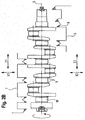
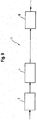
- FIG. 1 is shown in principle side view of a four-cylinder crankshaft as cast or forged blank.
- This crankshaft 2 has five main bearings 10 and four stroke bearings 11, between each cheeks 21 are arranged.
- both the main bearings and the stroke bearings are machined on this crankshaft 2.
- there are other areas that need to be processed in the context of crankshaft complete machining namely the face milling of the end faces 24 and the production of end centering holes and the processing of the pin side 19 including the local end processing.
- the face milling of the end faces 24 and the introduction of the centering holes in the context of the complete machining of the crankshaft on a production line according to the invention is an upstream first operation, which is also referred to as end machining.
- FIG. 2 is the crankshaft according to FIG. 1 shown in a schematic representation with arranged on carriers 6.7 rotary tools 8 for rotating the plan shoulders 9 according to the invention by means of Drehzentrurns the production line.
- the crankshaft 2 is clamped in a rotation center 3 in the direction of the production line, in accordance with FIG FIG. 2 the left side of the crankshaft are received by a workpiece headstock with workpiece drive and the right side of the crankshaft with a tailstock with a tip as a support.
- both the workpiece headstock and tailstock are not shown.
- a first carrier 6 for receiving rotary tools 8 and a second carrier 7 are also arranged for receiving rotary tools 8 on each side of the crankshaft in the longitudinal direction parallel to the longitudinal axis 5 of the crankshaft 2.
- the first carrier 6 can be delivered via an infeed axis X2 and the second carrier 7 can be delivered to the main bearings 10 of the crankshaft 2 via an infeed axis X1.
- the two tool carriers can also be moved in the longitudinal direction of the crankshaft along the CNC axes Z1 and Z2.
- the rotation of the plan shoulders 9 of the central pin 10 with the arranged on the respective carriers 6, 7 rotary tools 8 represents the actual first step in the complete machining of crankshafts according to the invention.
- the turning tools 8 are drawn only in a schematic plan view, wherein in an enlarged view of Detail X in the FIGS. 4 . 5 . 6 the details of the rotary operation and in FIG. 8 the details of the grinding operation are shown.
- the basic structural expression of the rotating tools arranged on the turning tools 8 can be seen.
- the sets of turning tools are mounted as a tool set as well as individually, presettable in the center of rotation.
- the arrangement of several turning tools on a respective carrier means that in the center of rotation an adjustability of the carrier in X1 or X2 direction as well as in Z1 or Z2 direction is provided.
- the adjustability of the carrier in the X direction corresponds to the delivery during rotation of the planets, while the adjustability in the Z direction serves to position the turning tools with respect to the insertion in the respective pin area for simultaneous rotation of opposing planar shoulders in their longitudinal position exactly.
- the turning tools are also individually adjustable, which can be done manually or automatically.
- the advantage of the arrangement of the turning tools 8 according to FIG. 2 Opposite to each other is that introduced during rotation forces that can lead to the deformation of the crankshaft, can be absorbed or compensated by the opposite counterpart. As a result of this bending-independent rotation of the plane shoulders 9 in the region of the central pins 10 of the crankshaft 2, the accuracy of the production of the crankshaft can be further improved. By simultaneously engaging the turning tools from two opposite sides on the crankshaft, besides the increased accuracy in the manufacture of the crankshaft, the machining times can be reduced as well.
- FIG. 2A shows an arrangement of the turning tools on the two serving as a tool holder supports in such a way that always plan shoulders 9 are rotated on one and the same side of the respective central pin, said arranged on the support 6 set of rotary tools, the left plan shoulders and on the support 7 arranged further set of turning tools rotates the right plan shoulders of the centric tenon.
- the axes Z1 and Z2 can be achieved on the axes Z1 and Z2 and a width correction of the pin locations or bearings.
- This has the advantage that the bearing widths not only by the default setting of the turning tools must be corrected, but also by the CNC axes Z1 and Z2.
- FIG. 2B is an arrangement of the turning tools on the two serving as a tool holder supports 6, 7 shown according to a further embodiment, which is different from the according to FIG. 2A characterized in that the respective carrier 6, 7 carry defined groups of rotary tools 8, with which defined groups of plan shoulders 9 of the central bearing are rotated.
- the division of the groups or work areas for the rotation of the plan shoulders can be carried out depending on the crankshaft to be produced in such a way that optimum technology parameters with regard to turning arise.
- the rotary tool sets can in turn be delivered via respective CNC axes for delivery in the X1 or X2 direction and in Z1 or Z2 direction in the longitudinal direction of the crankshaft or displaced or moved.
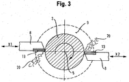
- FIG. 3 is a sectional view through the journal of a main bearing of the crankshaft 2 is shown.
- the indicated about the longitudinal axis 5 of the crankshaft arrow expresses that the crankshaft is driven to its processing by the workpiece headstock and set in rotation.
- the flat shoulder 9 is shown, in which simultaneously the opposite turning tools 8 are shown engaged, so that each of the turning tools 8 chips 20 are discharged.
- the fact that both turning tools are delivered simultaneously under the feed movement according to the feed axes X1 and X2 results in turning a high chip volume with simultaneous compensation of the resulting machining, introduced into the crankshaft forces.
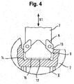
- FIG. 4 is the detail X according to FIG. 2 shown, in which a part of the second carrier 7, which carries an indexable insert 13 as a rotary tool 8 on each side, is shown.
- the indexable inserts 13 have just penetrated into the region of the central pin 10, which is a main bearing, and have started to rotate / the plan shoulders 9.
- These indexable inserts 13 are formed of either cemented carbide or polycrystalline diamond. These indexable inserts 13 are presettable, ie they are adjustable to the amount to be rotated so that the plan shoulders 9 can be rotated to the desired level with a single piercing in the storage area.
- the desired dimension is the measure after the turning process.
- the indexable inserts 13 have at their front directed in the direction of penetration nose a shape with which the relief groove 14 is rotated in the transition between the plan shoulders 9 and the actual storage area of the main lager.
- This undercut 14 forms an undercut to the immediate bearing surface in the diameter range of the bearing.
- the illustrated front side of the second carrier 7, which carries the two indexable inserts 13, has a recess in the middle, so that in the immediate storage area of the main bearing 10 after turning the planets 9 and the undercuts 14, the raw contour 16 in the region of the bearing still preserved. The rotation of the plan shoulders 9 and the undercuts 14 is thus decoupled from producing the desired bearing surface in the diameter range.
- FIG. 5 Finally, the detail X is according to FIG. 2 represented, in which, however, in contrast to the illustration according to FIG. 4 the second carrier 7 has been delivered in the direction of the feed axis X1 so far that the flat shoulders 9 have been rotated by the preset indexable inserts 13 to the desired intermediate or final dimensions, wherein at the same time the undercuts 14 have been rotated in addition to the immediate storage area in the diameter range of the main camp.
- the subsequent to this step grinding process can be performed with complete relief of the side surfaces of the grinding wheel 22.
- the grinding wheel 22 without being clamped between the plane shoulders when grinding the actual pin surface, within the range of the bearing at least move by a certain amount in the Z direction, but without touching the plan shoulders at all. This eliminates the extreme for a grinding wheel load on the outer edges and side edges, as occurs during Einstechschleifen.
- FIG. 7 is the crankshaft 2 according to FIG. 1 represented by marking all surfaces intended for grinding.
- the crankshaft 2 is rotationally driven about its longitudinal axis 5 in a conventional manner.
- the grinding of in FIG. 7 specified areas by means of a coarse grinding machine 4 for rough grinding of the central pin and the Hublagerstellen.
- the load on the grinding wheel during rough grinding of the pin is much lower, because the surface grinding of the high plan shoulders on the central pin completely eliminated at least during roughing.
- the already introduced during rough grinding in the crankshaft 2 loads are significantly reduced, so during processing a negative bending influence of the crankshaft 2 is minimized.
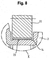
- FIG. 8 shows according to FIG. 2 with arranged grinding wheel 22 for rough grinding of the diameter ranges of the bearing journals.
- it is the grinding of the bearing journal 15 of a main bearing.
- the grinding wheels 22 preferably, galvanically coated grinding wheels are used for rough grinding of the pins of the cast iron or steel crankshafts.
- CBN grinding wheels are used with ceramic bond.
- the arrangement of the rotary tools in opposite engagement during rotation also ensures the compensation of otherwise introduced by the machining tool in the workpiece to be machined loads, so that this has an overall positive effect on the manufacturing accuracy.
- FIG. 9 time in a schematic representation of the basic structure of a production line 1 for carrying out the method according to the invention.
- the essential components of this production line 1 are the lathe or the turning center for rotating the plane-side parts in combination with a rough grinding machine.
- the division of the machining operations is carried out in such a way that when turning the plan shoulders of the centric pins are rotated. These are difficult to produce by grinding, since here can reach no acceptable service life for the grinding wheel.
- the lathe and the rough grinding machine the machines can each be assigned to the processes which can be implemented better, more cost-effectively and more advantageously for the quality of the crankshaft with the respective technology. For this reason, the plan sides of the centric pins and the undercut of the main bearing points are machined on the lathe. So it is the grinding wheels, with which the central pin as the main bearings are ground, wear significantly relieved.
- the finish grinding machine Allowance preferably only left for finishing, so that the service life of Abrasive wheel of a finishing grinding machine compared to a grinding wheel of a conventional grinding machine in the prior art, by means of which finish ground, is significantly increased.
- the forces introduced by the machining tool into the crankshaft are reduced, which has a positive effect on the accuracy of the crankshaft.
- the production line 1 is preceded by a milling machine, by means of which the end faces 24 of the crankshaft are in particular plan milled. Likewise preparatory centering holes are introduced.
- crankshafts After finishing the planing on the crankshaft and inserting the centering holes, turning on a center of rotation and rough grinding of the crankshaft on a roughing machine are performed. After this processing, further processing steps are carried out on the crankshaft, such as deep-hole drilling, rolling of punctures, heat treatments (such as hardening and tempering), end treatments, etc. (represented by the dots in FIG Fig. 9 ). Depending on the design of the crankshaft, these machining processes can vary, ie machining processes can be omitted or added. After these machining processes, the crankshafts are then ground to their main and stroke bearings and at the ends (flange / pin). After finish grinding, further processing is done, such as balancing, superfinishing, final measurements, etc.
- FIG. 10 represents an enlarged view of a portion of a central pin in which a rotary tool 8 is shown enlarged with an indexable insert 13.
- the plan shoulders 9 are rotated next to the immediate bearing point of the central pin.
- the plan shoulders 9 are preferably finished, so that these plan shoulders 9 no longer need to be ground during later processing steps.
- the rough contour 16 is located, which is an oversize 26 differs from the final contour 17. Also entered is the allowance 23, which results after rough grinding.
- the major part of the oversize 26 is removed in the course of rough grinding, the rough grinding as far as possible to the final dimension, ie the final contour 17 can be brought.
- the grinding wheels for coarse grinding undergoes no heavy wearing wear and stress common in the prior art, where both the faces and the pins are ground.
- the rough grinding a measure-optimized grinding of the shape is realized that only a slight oversize 23 can remain with respect to the final contour 17, is already ensured by the rough grinding, the loads of the finished grinding wheels are lower on the one hand later finished grinding and on the other hand in addition to their lifetime increase When grinding in the workpiece registered load is lower, so that in finishing grinding also a higher accuracy of the crankshaft can be achieved.
- the registered CNC axes X and Z make it possible that after completion of the rotation of the face shoulder 9 via an interpolating movement of the X and Z axis of the undercut 14 can be rotated next to the immediate bearing. This is especially after the arrangement of the turning tools after FIG. 2A advantageously possible.
Description
Die Erfindung betrifft ein Verfahren zur Komplettbearbeitung zumindest von unbearbeiteten Zapfen und Planschultern geschmiedeter oder gegossener Rohlinge einer Kurbelwelle.The invention relates to a method for the complete machining of at least unprocessed pins and plane shoulders forged or cast blanks of a crankshaft.
Da Kurbelwellen ein zentrales Bauelement insbesondere bei Hubkolben-Verbrennungskraftmaschinen darstellen und diese Art von Verbrennungskraftmaschinen seit Jahrzehnten erfolgreiche Anwendung gefunden hat, hat sich auch die Fertigungstechnik ebenso lange mit einer Verbesserung nicht nur der Genauigkeit bei der Herstellung sondern auch der Ökonomie der Herstellung befasst.Since crankshafts represent a central component, in particular in reciprocating internal combustion engines, and this type of internal combustion engine has been used successfully for decades, manufacturing technology has also long concerned itself with an improvement not only in manufacturing accuracy but also in the economics of production.
Eine Schwierigkeit bei der Komplettbearbeitung von Kurbelwellen besteht darin, dass die häufig als Schmiedeteile oder Gussteile gelieferten Kurbelwellenrohlinge einer Bearbeitung nicht nur der Haupt- und Hublagerzapfen, sondern auch der Planseiten der Wangen, der stimseitigen Planseiten sowie eines Anschlussflansches und von Zentrier- und/oder Ölversorgungsbohrungen unterzogen werden müssen.A difficulty in the complete machining of crankshafts is that the crankshaft blanks often supplied as forgings or castings, a machining of not only the main and thrust bearing pin, but also the plan sides of the cheeks, the front end sides and a flange and of centering and / or oil supply holes must be subjected.
Die geschmiedeten oder gegossenen Rohlinge weisen ein relativ großes Aufmass, insbesondere an den entscheidenden Stellen wie beispielsweise Hauptlager, Hublager, Planschultern, Passlager auf, welches durch eine mechanische Bearbeitung abgetragen werden muss. Damit ein Rohling einer nachfolgenden mechanischen Bearbeitung überhaupt unterzogen werden kann, muss dieser Rohling an seinen Enden planseitig bearbeitet werden, und es müssen dort Zentrierbohrungen eingebracht werden. Dies ist erforderlich, damit die zu bearbeitende Kurbelwelle im Interesse einer zu erzielenden hohen Fertigungsgenauigkeit exakt und wiederholbar auf den jeweiligen Bearbeitungsmaschinen eingespannt werden kann.The forged or cast blanks have a relatively large oversize, especially at the crucial points such as main bearing, crank bearings, plan shoulders, foothold, which must be removed by mechanical machining. In order for a blank to be able to undergo subsequent mechanical processing at all, this blank must be machined at its ends on the plane, and centering bores must be introduced there. This is necessary so that the crankshaft to be machined can be clamped exactly and repeatably on the respective processing machines in the interests of achieving high production accuracy.
Rohlinge im Sinne dieser Erfindung sind geschmiedete oder Gussrohlinge, welche lediglich an deren Enden planseitig bearbeitet sind und Zentrierbohrungen aufweisen.Blanks in the context of this invention are forged or cast blanks, which are processed on the plan side only at the ends and have center holes.
Bei den Rohlingen einer Kurbelwelle müssen Hauptlager, Hublager, Einstiche und Hinterstiche, Passlager, Flansch- und Zapfendurchmesser, gegebenenfalls konzentrische Profile sowie Wangenseitenflächen und Wangenaußendurchmesser einschließlich Fasen mechanisch bearbeitet werden. Hinzu kommt noch, dass Kurbelwellen mit Ölbohrungen versehen werden müssen, so dass zahlreiche Fertigungsschritte nötig sind, um aus einem geschmiedeten oder gegossenen Kurbelwellenrohling ein fertiges, komplett bearbeitetes Bauteil zu machen.For the blanks of a crankshaft, main bearings, crank bearings, recesses and undercuts, ball bearings, flange and journal diameters, possibly concentric profiles as well as cheek side surfaces and outer cheek diameters, including chamfers, must be machined mechanically. In addition, crankshafts must be provided with oil wells, so that numerous manufacturing steps are necessary to make a forged or cast crankshaft blank a finished, completely machined component.
Der Gang der technischen Entwicklung bezüglich der Fertigungstechnik von Kurbelwellen orientierte sich dabei darauf, die verschiedenen technologischen Fertigungsoperationen wie Fräsen, Drehen, Schleifen und Bohren weitestgehend zusammenzufassen, und zwar nach Möglichkeit auf einzelnen Fertigungszentren. In diese Entwicklung eingebettet war auch der Trend, vor allen Dingen wegen der damit erzielbaren hohen Fertigungsgenauigkeit, den Anteil der Schleifoperationen an der Anzahl der Operationen zur kompletten Herstellung der Kurbelwelle zu erhöhen. Dennoch werden in Fertigungslinien zur Kurbelwellenkomplettbearbeitung Dreh- und Schleifmaschinen zusammengefasst, um insbesondere jene Operationen, welche günstiger durch Drehen hergestellt werden können, auf einer Drehmaschine, jedoch jene Operationen, welche genauer und besser auf Schleifmaschinen herstellbar sind, auf eben diesen Schleifmaschinen durchzuführen.The course of technical development in crankshaft production technology was based on combining the various technological manufacturing operations such as milling, turning, grinding and boring as far as possible, if possible on individual machining centers. Embedded in this development was also the trend, above all because of the achievable high manufacturing accuracy, to increase the proportion of grinding operations in the number of operations for the complete production of the crankshaft. Nevertheless, in finishing lines for complete crankshaft turning and grinding machines are summarized to perform in particular those operations that can be made more favorable by turning on a lathe, but those operations that are more accurate and better to produce grinding machines on just these grinders.
Wegen der relativ großen Aufmaße, welche durchaus bis zu 5 mm und mehr betragen können, ist die Bearbeitung einer Kurbelwelle je nach Ausführung, Größe, Härte, Art und Losgröße unterschiedlich. In jedem Fall beginnt die Bearbeitung mit einer Grobbearbeitung, bei welcher beispielsweise die Kurbelwelle an den Enden auf die richtige Länge gefräst wird und an diesen Enden auch Zentrierbohrungen eingebracht werden. Daran schließt sich eine Bearbeitung der Hauptlagerflächen und auch der Hublager an. Als Bearbeitungstechniken werden für diese Grobbearbeitung das Drehen und Fräsen, insbesondere Wirbeifräsen, sowie Drehräumen in großem Maße angewandt. Für die Hauptlagerflächen kann zum Beispiel auch ein Grobschleifen erfolgen. Hublager werden überwiegend gefräst. Drehräumen und auch Schleifen werden ebenfalls eingesetzt.Due to the relatively large oversize, which can be up to 5 mm and more, the machining of a crankshaft is different depending on the design, size, hardness, type and lot size. In any case, the processing begins with a rough machining, in which, for example, the crankshaft is milled at the ends to the correct length and at these ends and center holes are introduced. This is followed by machining of the main bearing surfaces and also the stroke bearings. As machining techniques, turning and milling, in particular whirling, as well as turning spaces are widely used for this rough machining. For the main bearing surfaces, for example, a rough grinding can be done. Lifting bearings are mainly milled. Turning spaces and loops are also used.
Zu einer Komplettbearbeitung einer Kurbelwelle gehören zahlreiche weitere Verfahrensschritte wie das Bohren von Ölkanälen, welches beispielsweise in einer Tiefenbohrtechnik realisiert werden kann, das Induktionshärten zur Verbesserung der Verschleißfestigkeit, indem die Lagerlaufflächen gehärtet und die Dauerfestigkeit durch Erzeugen von Restdruckspannungen insbesondere bei den Radien erhöht wird. Dieser Vorgang wird durch Erwärmen, Abschrecken und Vergüten realisiert. Weitere technologische Verfahren sind das Rollen der Radien bzw. das Radieninduktionshärten zur Erhöhung der Dauerfestigkeit. Ebenso kann das Nitrieren einer fertig bearbeiteten Kurbelwelle zur Verbesserung des Verschleiß- und Ermüdungsverhaltens eingesetzt werden. Haupt- und Hublager werden häufig auch geschliffen wie ebenso die Enden der Kurbelwellen, d. h. deren Zapfen und Flanschenden. Das Schleifen hat insbesondere Vorteile bezüglich Rundheit, Oberflächenqualität, Geradheit, gegebenenfalls Konizität, Maßhaltigkeit etc.Complete machining of a crankshaft involves numerous further process steps, such as drilling oil passages, which can be realized, for example, in a deep drilling technique, induction hardening to improve wear resistance by hardening the bearing raceways and, in particular, fatigue strength by generating residual compressive stresses is increased at the radii. This process is realized by heating, quenching and tempering. Further technological processes are the rolling of the radii or the induction hardening of the radii to increase the fatigue strength. Likewise, the nitriding of a finished crankshaft can be used to improve the wear and fatigue behavior. Main and stroke bearings are often ground as well as the ends of the crankshaft, ie their pin and flange ends. The grinding has particular advantages in terms of roundness, surface quality, straightness, optionally conicity, dimensional accuracy, etc.
Unter Komplettbearbeitung soll im Rahmen der vorliegenden Erfindung ein komplettes Bearbeiten von unbearbeiteten zentrischen Zapfen wie auch unbearbeiteten Hublagerzapfen sowie deren jeweiligen, die Zapfen umgebenden ebenfalls unbearbeiteten Planschultern, von geschmiedeten oder gegossenen Rohlingen einer Kurbelwelle verstanden werden. Die Erfindung schließt zwar sämtliche Vorgänge für das komplette Bearbeiten einer Kurbelwelle im weitesten Sinne ein, der Kern der Erfindung erstreckt sich jedoch auf das vorstehend genannte Bearbeiten von Zapfen und Planschultern an geschmiedeten oder gegossenen Rohlingen einer Kurbelwelle.Complete machining in the context of the present invention is to be understood as meaning a complete machining of unprocessed centric pins as well as unmachined crankpins as well as their respective planing shoulders, which are also unprocessed around the pins, of forged or cast blanks of a crankshaft. While the invention includes all operations for the complete machining of a crankshaft in the broadest sense, the gist of the invention extends to the above-mentioned machining of pins and face shoulders on forged or cast blanks of a crankshaft.
Im Stand der Technik ist es prinzipiell bekannt, Planseiten drehend zu bearbeiten (s.beispielsweise
Das Wirbelfräsen oder Drehräumen hat bei der Kurbelwellenfertigung große Verbreitung gefunden. Die Nachteile dieser Verfahren, d. h. des Wirbelfräsens oder Drehräumens, bestehen oft darin, dass diese Verfahren prinzipiell trocken durchgeführt werden, d. h. eine Kühlflüssigkeit wird nicht eingesetzt. Die Werkzeuge für das Drehräumen und Wirbelfräsen sind darüber hinaus sehr kompliziert, weil es sich dabei um scheibenartige Bauteile handelt, welche an den Stirnseiten im Umfangsbereich, die eigentliche spanabhebende Funktion realisierende Plättchen auf weisen. Diese Plättchen müssen nun sehr genau individuell justiert werden, damit während der spanabhebende Bearbeitung eine möglichst gleichmäßige Materialabtragung realsiert wird und andererseits die Plättchen auch gleichmäßig belastet werden. Da diese Plättchen in definierten Abständen am Umfang angeordnet sind, entsteht auch eine relativ unsaubere Oberflächenkontur, welche auch als schuppenartig bezeichnet werden kann. Das Ergebnis der Grobbearbeitung hat unter diesen Umständen negativen Einfluss auf die sich daran anschließenden Feinbearbeitungsvorgänge, weil die dafür verwendeten Werkzeuge zunächst die rauhe und unebene Oberfläche ausgleichen müssen. Das wiederum setzt voraus, dass ein relativ großes Aufmaß für die Endbearbeitung im Ergebnis der Grobbearbeitung beibehalten werden muss. Die für das Wirbelfräsen oder Drehräumen verwendeten Werkzeuge benötigen darüber hinaus lange Zeiten, um die verschlissenen Plättchen komplett auszutauschen. Dafür sind häufig mehrere Stunden erförderlich. Dies führt zu einem Verteuern des Herstellungsprozesses. Da Kurbelwellen jedoch häufig in Serienfertigung gefertigt werden, muss nach kostengünstigen Lösungen gesucht werden.The Wirbelfräsen or Drehräumen has found widespread use in crankshaft production. The disadvantages of these methods, ie, the vortex milling or Drehräumens, often consist in that these methods are carried out in principle dry, ie a cooling liquid is not used. The tools for turning and whirl milling are also very complicated because they are disc-like components, which have at the end faces in the peripheral region, the actual chip-removing function realizing platelets. These platelets must now be adjusted very precisely individually, so that as even as possible material removal is realized during the machining and on the other hand, the platelets are evenly loaded. Since these plates are arranged at defined intervals on the circumference, also creates a relatively impure surface contour, which can also be referred to as scale-like. The result of rough machining Under these circumstances, it has a negative influence on the subsequent finishing operations, because the tools used for this purpose first have to compensate for the rough and uneven surface. This in turn implies that a relatively large finishing allowance must be maintained as a result of roughing. In addition, the tools used for the whirling or turning operations require long times to completely replace the worn flakes. For several hours are often necessary. This leads to an increase in the cost of the manufacturing process. However, as crankshafts are often mass-produced, cost-effective solutions must be sought.
Während der Grobbearbeitung wird bekanntermaßen relativ viel Material abgetragen, was insbesondere bei Verfahren mit einer Trockenbearbeitung zu einem hohen Wärmeeintrag in die zu bearbeitende Kurbelwelle führt. Dieser hohe Wärmeeintrag führt neben den hohen Bearbeitungskräften infolge des Eingriffs der Werkzeuge am zu bearbeitenden Bauteil zu einer Deformation des Bauteils mit nachteiligem Einfluss auf die spätere zu erreichende Genauigkeit. Der Wärmeeintrag in die Kurbelwelle infolge der Grobbearbeitung führt des Weiteren zum Freisetzen von Spannungen im Bauteil, welche ebenfalls zu Verzügen des Bauteils führen. Darüber hinaus führen die Grobbearbeitungen zu deutlich höheren Belastungen der Werkzeuge in diesem technologischen Schritt im Vergleich zur Fein- bzw. Endbearbeitung.During roughing, as is known, a relatively large amount of material is removed, which leads to a high heat input into the crankshaft to be processed, in particular in the case of processes with dry machining. This high heat input results in addition to the high machining forces due to the engagement of the tools on the component to be machined to a deformation of the component with adverse influence on the later to be achieved accuracy. The heat input into the crankshaft as a result of rough machining also leads to the release of stresses in the component, which also lead to distortion of the component. In addition, the coarse machining operations lead to significantly higher loads on the tools in this technological step compared to finishing or finishing.
Daher ist versucht worden, das Wirbelfräsen und Drehräumen durch Schleifoperationen zu ersetzen. Bei der Bearbeitung von derartigen Rohlingen ist jedoch zu beachten, dass wegen des erforderlichen großen Materialabtrags Vorschleifoperationen in der Regel mit relativ hohen Schleifscheibenabnutzungen verbunden sind (insbesondere an den Planseiten).Therefore, it has been attempted to replace the whirl milling and turning spaces by grinding operations. In the processing of such blanks, however, it should be noted that because of the required large material removal pre-grinding operations are usually associated with relatively high Schleifscheibenabnutzungen (especially on the plan pages).
Das Schleifen selbst wird in aller Regel als nasser Bearbeitungsvorgang durchgeführt, weil mit Kühlschmierstoff gearbeitet wird. Damit wird durch das Schleifen weniger Wärme in das Bauteil eingebracht, und auch die Bearbeitungskräfte sind geringer, sodass die Deformationen infolge der Verarbeitung an der Kurbelwelle beim Schleifen reduziert werden können. Dies hat direkten positiven Einfluss auf die Genauigkeit der Kurbelwelle, sodass auch ein besserer Rundlauf einer fertigen Kurbelwelle erzielbar ist.The grinding itself is usually carried out as a wet machining process, because it works with cooling lubricant. As a result, less heat is introduced into the component as a result of the grinding, and also the machining forces are lower, so that the deformations due to the processing on the crankshaft during grinding can be reduced. This has a direct positive influence on the accuracy of the crankshaft, so that a better concentricity of a finished crankshaft can be achieved.
Dies ist besonders kritisch beim Bearbeiten der Planschultern der zentrischen Zapfenbereiche, weil diese Planschultern eine deutlich größere Höhe aufweisen als die Planschultern an den Hublagerzapfen der Kurbelwelle. Für die Wirbelfräsverfahren bzw. Drehräumverfahren bedeutet dies, dass die zahlreichen am Außenumfang der Werkzeuge angeordneten Schneidplättchen beim Bearbeiten der Planschultern eine starke einseitige Belastung erfahren, während große Teile dieser Schneidplättchen während des Bearbeitens der Planschultern überhaupt noch nicht im Eingriff mit dem zu schleifenden Werkstück, der Kurbelwelle, sind. Dadurch verschleißen die Bearbeitungswerkzeuge relativ rasch und müssen in vergleichsweise kurzen Intervallen mit neuen Schneidplättchen bestückt werden. Dies führt zu einer Verteuerung des Herstellungsprozesses, weil die Neubestückung ein zeitaufwendiger Vorgang ist. Erst nachdem die Planschultern komplett bearbeitet worden sind, greifen die übrigen Bereiche der Wirbelfräs- bzw. Drehräumwerkzeuge in die Bearbeitung ein, indem sie die unmittelbaren Zapfenbereiche bearbeiten. Wie zuvor bereits beschrieben ist das Ergebnis der Drehräum- bzw. Wirbelfräsbearbeitung eine relativ "schuppige" Oberfläche. Eine derartige unregelmäßige und relativ rauhe Oberfläche hat für nachfolgende Fertigbearbeitungsvorgänge erhebliche Nachteile. Werden die Fertigbearbeitungsvorgänge wie üblich durch Schleifen realisiert, so müssen die dort eingesetzten Werkzeuge in eine relativ unebene und rauhe Oberfläche eingreifen, was einen erhöhten Verschleiß der dafür eingesetzten Schleifscheiben nachsichzieht. Wegen der nur relativ rauhen Oberfläche, welche durch dieses Vorbearbeiten durch Wirbelfräsen bzw. durch Drehräumen erreicht werden kann, muss auch ein relativ großes Aufmaß gegenüber dem zu erzielenden Endmaß nach der Grobbearbeitung beibehalten werden, damit sämtliche Fehler im Wege der Endbearbeitung noch ausgeglichen werden können. Die so bearbeiteten Kurbelwellenrohlinge werden auch als vorbearbeitete Kurbelwellen bezeichnet. Für diese vorbearbeiteten Kurbelwellen wird dann eine übliche Fertigbearbeitung in der Gestalt durchgeführt, dass zunächst ein Vorschleifen durchgeführt wird, woran sich ein Fertigschleifen bzw. Feinschleifen anschließt. Diese beiden Verfahren werden in der Regel durch zwei unterschiedliche Schleifscheiben durchgeführt, weil zum einen noch ein relativ großes Aufmaß abzuschleifen ist, was für eine Feinschleifmaschine eine zu große Belastung darstellen würde, und weil zum anderen die Oberfläche relativ rauh ist, was ebenfalls zu einem relativ raschen Verschleiß einer Feinschleifscheibe führen würde, mit dem negativen Ergebnis, dass die hohen Qualitätsanforderungen an eine Kurbelwelle nicht oder nur schwer erreichbar wären.This is particularly critical when editing the plan shoulders of the central pin areas, because these plan shoulders have a much greater height than the plan shoulders on the crankpins of the crankshaft. For the Wirbelfräsverfahren or Drehräumverfahren this means that the numerous arranged on the outer periphery of the tools cutting edges when editing the plan shoulders undergo a strong one-sided load, while large Parts of these cutting plates are not yet in engagement with the workpiece to be ground, the crankshaft, during the machining of the planing shoulders. As a result, the processing tools wear relatively quickly and must be equipped at relatively short intervals with new cutting tips. This leads to an increase in the cost of the manufacturing process, because the replacement is a time-consuming process. Only after the face shoulders have been completely machined, the remaining areas of the Wirbelfräs- or Drehräumwerkzeuge engage in the processing by editing the immediate pin areas. As previously described, the result of turn-mill machining is a relatively "scaly" surface. Such an irregular and relatively rough surface has considerable disadvantages for subsequent finishing operations. If the finishing operations as usual realized by grinding, the tools used there must engage in a relatively uneven and rough surface, which nachsichzieht increased wear of the grinding wheels used for it. Because of the only relatively rough surface, which can be achieved by this pre-machining by whirling or by turning, a relatively large oversize compared to the final size to be achieved after roughing must be maintained so that all errors in the way of finishing can still be compensated. The machined crankshaft blanks are also referred to as pre-machined crankshafts. For these pre-machined crankshafts then a custom finishing is performed in the form that first a pre-grinding is performed, followed by a finish grinding or fine grinding followed. These two methods are usually performed by two different grinding wheels, because on the one hand still a relatively large oversize is to be ground, which would be too great a burden for a fine grinding machine, and because on the other hand, the surface is relatively rough, which also to a relative Rapid wear of a fine grinding wheel would result, with the negative result that the high quality requirements for a crankshaft would be difficult or impossible.
Zwar ist versucht worden, diese Nachteile zu minimieren, indem gemischte Verfahren zur Bearbeitung von Kurbelwellenrohlingen, d. h. Verfahren, welche aus Drehräumen und Wirbelfräsen sowie Schleifen bestehen, miteinander in der Gestalt zu kombinieren, dass bei einem Hauptlager die Planseiten mittels Wirbelfräsen bzw. Drehräumen bearbeitet worden sind, woran sich ein Schleifen des Hauptlagerzapfens anschloss, damit eine Lünette für die weiteren Bearbeitungsvorgänge dort angestellt werden kann. Doch diese kombinierten Verfahren behalten letztendlich die Nachteile bei, welche sich in Verbindung mit dem Wirbelfräsen und Drehräumen am Bauteil direkt niederschlagen. Dies sind die hohen Belastungen auch infolge der Trockenbearbeitung, die hohe Oberflächenrauhigkeit und die Deformationen der Kurbelwelle infolge dieser Bearbeitung.While attempts have been made to minimize these drawbacks by combining blended methods of machining crankshaft blanks, ie, processes consisting of torsion and whirl milling and grinding, into one another in such a way that, in a main bearing, the face sides have been machined by means of whirling are what was followed by a grinding of the main journal, so that a bezel for the further processing operations can be made there. However, these combined methods ultimately retain the disadvantages that are directly reflected in the component in connection with the whirling and turning operations. These are the high loads also due to the dry machining, the high surface roughness and the deformations of the crankshaft as a result of this machining.
Um die vorstehend genannten Nachteile der bisher gängigen Bearbeitungsverfahren für Kurbelwellen bei der Grobbearbeitung wie Drehräumen und Wirbelfräsen zu beseitigen, ist versucht worden, die Kurbelwellen komplett zu schleifen, d. h. die Grobbearbeitung durch ein Grobschleifen zu realisieren.In order to eliminate the above-mentioned disadvantages of the hitherto common machining methods for crankshafts during roughing, such as turning spaces and whirl milling, it has been attempted to grind the crankshafts completely, that is to say to remove them. H. to realize the rough machining by rough grinding.
Im Vordergrund stand bei den bekannten Herstellungsverfahren für Kurbelwellen, bei denen die Kurbelwellenrohlinge bereits grob vorbearbeitet sind; d. h. bei denen sowohl Planflächen als auch Zapfenbereiche beispielsweise auch grobvorgeschliffen worden sind, dennoch die Fertigbearbeitung der Hub- wie auch der Hauptlagerzapfen sowie der Planschultern auf einer Fertigschleifmaschine, welche die Vorgänge des Vorschlefens, und des Fertigschleifens realisiert. Bereits die Reihenfolge der Bearbeitung von Hublagerzapfen und Hauptlagerzapfen hat einen Einfluss auf die später zu erzielende Genauigkeit. Damit ist diesem Verfahrensabschnitt nicht nur bisher höchste Aufmerksamkeit gewidmet worden, es sind sogar auch zur Durchführung dieser komplexen Schleifvorgänge spezielle Schleifscheiben entwickelt worden, einschließlich solcher Schleifscheiben, bei denen eine Nachjustierung der Schleifscheibenbreite, möglich, war. Dies zeigt, dass zur Sicherstellung vor allem der Qualität der Kurbelwellen insbesondere die Schleifoperationen perfektioniert worden sind.In the foreground stood in the known manufacturing process for crankshafts, in which the crankshaft blanks are already roughly preprocessed; d. H. in which both flat surfaces and journal areas, for example, have been rough ground, but the finishing of the hub as well as the main journals and the plan shoulders on a finishing grinding machine, which realizes the operations of Vorschlefens, and finish grinding. Already the order of processing of crankpins and main journal has an impact on the later achieved accuracy. Thus, this section of the process has not only been given the highest attention so far, special grinding wheels have even been developed for carrying out these complex grinding operations, including those grinding wheels in which a readjustment of the grinding wheel width was possible. This shows that, in particular, the grinding operations have been perfected to ensure above all the quality of the crankshafts.
Trotz dieser perfektionierten Herstellungsweise im Bereich des Schleifens ist festgestellt worden, dass insbesondere die Schleifscheibenabnutzung infolge des Schleifens von Planschultern und Lagerzapfen unbefriedigend hoch ist. Dies trifft insbesondere für die großen Planschultern an den zentrischen Zapfenbereichen und insbesondere dabei für den Vorgang des Grobschleifens zu. Dieses Grobschleifen wurde durch ein Einstechschleifen realisiert, sodass beide den jeweiligen Zapfen zwischen sich einschließenden Planschultern gleichzeitig geschliffen wurden. Wenn die Schleifscheibe nun zum Zwecke des Schleifens der Planschultern in diesen Bereich einsticht, werden im Grunde genommen nur die unmittelbaren Kantenbereiche der Schleifscheibe dann aber höchstbelastet, während die über der Breite der Schleifscheibe dazwischen angeordneten Schleifkörner keinerlei Schleifarbeit zu verrichten haben. Dies führt zu einem hohen Verschleiß der Grobschleifscheiben, sodass die Standzeit dieser Schleifscheiben unvertretbar gering ist. Man hat bei dieser Art von Grobschleifen daher nur so viel wie unbedingt nötig vom Aufmaß an den zentrischen Lagerstellen abgeschliffen, was zur Folge hat, dass für die Fertigbearbeitung noch ein erhebliches Aufmaß verbleibt. Verbesserte Schleifscheibenmaterialien haben nicht ausreichend Abhilfe bei diesem Problem geschaffen.Despite this perfected grinding production, it has been found that, in particular, grinding wheel wear due to grinding of face shoulders and journals is unsatisfactorily high. This is especially true for the large plan shoulders on the central pin areas and in particular for the process of rough grinding. This coarse grinding was realized by a plunge grinding, so that both the respective pin between enclosing plan shoulders were ground simultaneously. If the grinding wheel now punctures in this area for the purpose of grinding the plane shoulders, then basically only the immediate edge areas of the grinding wheel are subjected to the highest load, while the abrasive grains arranged in-between over the width of the grinding wheel have no grinding work to do. This leads to high wear of the rough grinding wheels, so that the service life of these grinding wheels is unacceptably low. Therefore, in this type of rough grinding, only as much as is absolutely necessary has been ground off the oversize at the centric bearing points, with the result that a considerable oversize remains for the finish machining. Improved grinding wheel materials have not adequately remedied this problem.
Die erheblichen Nachteile hinsichtlich Genauigkeit, benötigter Leistung und Taktzeit sowie Kosten der Verfahren Drehräumen und Wirbelfräsen, Grobschleifen sowie deren Kombination erfüllen daher nicht die insbesondere für Serienfertigung bestehenden Forderungen.The significant disadvantages in terms of accuracy, power required and cycle time and costs of the process rotating chambers and whirl milling, rough grinding and their combination therefore do not meet the existing in particular for mass production requirements.
Der Erfindung liegt daher die Aufgabe zugrunde, ein Verfahren zur Komplettbearbeitung von allenfalls an den Enden planseitig vorbearbeiteten Kurbelwellenrohlingen sowie eine zur Durchführung des Verfahrens erforderliche Fertigungslinie mit den entsprechenden Fertigungsoperationen für eine Serienfertigung derart bereitzustellen bzw. zu optimieren, dass der Werkzeugverschleiß sowie die Werkzeugkosten und damit die Stückkosten der Kurbelwellen verringert werden und der gesamte Herstellungsprozess kostengünstiger erfolgen kann, und zwar bei hoher Herstellungsgenauigkeit der Kurbelwellen.The invention is therefore an object of the invention to provide a method for complete machining of possibly at the ends of the plane pre-machined crankshaft blanks and a process required for carrying out the production line with the corresponding manufacturing operations for mass production or to optimize that the tool wear and tooling costs and thus the unit cost of the crankshaft can be reduced and the entire manufacturing process can be done more cost-effectively, with high manufacturing accuracy of the crankshaft.
Diese Aufgabe ist durch ein Verfahren gemäß dem Anspruch 1 gelöst.This object is achieved by a method according to claim 1.
Überraschenderweise hat sich erfindungsgemäß gezeigt, dass - entgegen dem bisherigen Gang der technischen Entwicklungen - durch ein Trennen bzw. ein Aufteilen der verschiedenen Schritte des gesamten Herstellungsprozesses, und zwar in Abkehr vom bisher üblichen Vorgehen, Abhilfe für die genannten Probleme geschaffen werden kann, indem vor allem der Teil der Grobbearbeitung des Grobschleifens, Drehräumens oder Wirbelfräsens, welcher das Schleifen der großen Planschultern an den zentrischen Zapfen beinhaltet, statt dessen einem normalen Drehvorgang unterzogen wird. Da die Grobschleifscheiben und die Werkzeuge für das Drehräumen bzw. Wirbelfräsen nun nicht mehr zum Bearbeiten der Planschultern an den zentrischen Zapfenbereichen eingesetzt werden müssen, erhöht sich deren Standzeit erheblich. Die Werkzeuge erfahren aber auch eine gleichmäßigere Belastung, da beim Grobbearbeiten nur der Zapfen die Schnittplättchen bzw. die Schleifscheibenkörner sofort und sämtlich in Eingriff gelangen. Einen besonderen Vorteil bietet das Grobschleifen insbesondere der zentrischen Zapfen, nachdem deren Planschultern gedreht worden sind. Beim Grobschleifen kann die Schnittgeschwindigkeit gegenüber dem Drehfräsen bzw. Drehräumen, wobei beim Drehräumen ein feststehendes Werkzeug vorhanden ist, deutlich gesteigert werden. Trotz der erhöhten Schnittgeschwindigkeit ist der Wärmeeintrag beim Schleifen erheblich geringer, wodurch die Kurbelwelle eine geringere Deformation erfährt und wodurch neben einer glatteren und gleichmäßigeren Oberfläche auch ein geringerer Rundlaufschlag erzielt werden kann. Bei dem erfindungsgemäßen Grobschleifen lediglich der zentrischen Zapfenbereiche am Rohling kann damit auch wegen des Schleifens unter Zufuhr von Kühl- und Schleiföl ein größerer Teil des Aufmaßes geschliffen werden, welches am unbearbeiteten Rohling vorhanden ist. Das bedeutet, dass mit dem erfindungsgemäßen Verfahren die Grobbearbeitung bis weit in den Teil des Aufmaßes hinein durchgeführt werden kann, welches bisher für das bekannte Fertigschleifen vorgesehen sein musste. Damit entlastet das Grobschleifen nicht nur die Werkzeuge beim Fertigschleifen, beim Fertigschleifen muss daher auch erheblich weniger Material abgetragen werden, um auf Endmaß zu schleifen. Deshalb kann beim Fertigschleifen dieses in einem Zuge erfolgen, sodass die bisher übliche Aufteilung in Vorschleifen mit einer Vorschleifscheibe und Fertigschleifen mit einer Fertigschleifscheibe oft nicht mehr erforderlich ist. Vielmehr kann in einem Zuge mit einer einzigen Feinbearbeitungsschleifscheibe geschliffen werden, ohne dass diese überlastet wird. Dadurch, dass beim Feinschleifen weniger Aufmaß abzutragen ist, vermindern sich auch die Belastungen auf die Kurbelwelle während des Fertigschleifens, was direkt positiven Einfluss auf die erzielbare Qualität der Kurbelwelle hat.Surprisingly, it has been found according to the invention that - contrary to the previous course of technical developments - can be created by separating or dividing the various steps of the entire manufacturing process, in departure from the usual procedure, remedy for the above problems by in particular, the part of the coarse machining of rough grinding, Drehräumens or whirl milling, which includes the grinding of the large plan shoulders on the central pin, instead of a normal turning operation is subjected. Since the coarse grinding wheels and the tools for lathe milling or whirl milling no longer have to be used to machine the plane shoulders on the central journal areas, their service life increases considerably. But the tools also experience a more uniform load, since when roughing only the pins, the cutting plates or the grinding wheel grains immediately and all engage. A particular advantage is the coarse grinding in particular of the central pin after their plan shoulders have been rotated. When rough grinding, the cutting speed can be significantly increased compared to the rotary milling or twisting spaces, wherein a fixed tool is available when twisting. Despite the increased cutting speed, the heat input during grinding is considerably lower, as a result of which the crankshaft undergoes less deformation and, in addition to a smoother and more uniform surface, a lower radial runout can also be achieved. In the rough grinding according to the invention only the central pin areas on the blank can thus be ground because of the grinding under supply of cooling and grinding oil, a larger part of the allowance, which is present on the raw blank. This means that with the method according to the invention, the rough machining can be carried out far into the part of the allowance, which previously had to be provided for the known finish grinding. Thus, rough grinding not only relieves the tools during finish grinding, therefore, in finishing grinding, considerably less material has to be removed in order to reach final dimensions grind. Therefore, this can be done in one go during finish grinding, so that the previously customary division into rough grinding with a roughing wheel and finish grinding with a finish grinding wheel is often no longer required. Rather, can be ground in one go with a single finishing grinding wheel, without being overloaded. The fact that less oversize is to be removed during fine grinding also reduces the loads on the crankshaft during finish grinding, which has a direct positive influence on the achievable quality of the crankshaft.
Die erfindungsgemäße Kombination von Drehen der Planschultern und Grobschleifen der Zapfenbereiche wird durch eine intelligente Aufteilung dieser Fertigungsprozesse im Sinne einer Verformungsoptimierung der Kurbelwelle während der Bearbeitung und im Sinne einer Aufmaßoptimierung durchgeführt. Bezüglich des technologischen Ablaufs wird erfindungsgemäß nun das gedreht (die Planschultern der zentrischen Zapfen), was durch Drehen optimal hinsichtlich Werkstückverformung, Wärmeeintrag, Bearbeitungsgenauigkeit deutlich effektiver herstellbar ist, wohingegen der Rest der Bearbeitung von hohen Belastungen entlastet wird. Es wird also bezüglich des technologischen Ablaufs das Drehen bewusst wieder eingesetzt und aus einer kompletten Schleifbearbeitung sozusagen herausgelöst, um den Gesamtfertigungsprozess insgesamt kostengünstiger und mit höherer Qualität des Werkstückes durchführen zu können. Das Schleifen wird mittels einer Grobschleifbearbeitung insgesamt genauer durchgeführt werden als eine Bearbeitung mittels Schleifens von Planschultern und Zapfenbereichen in einem Zuge im Wege eines Einstechschleifvorganges.The combination according to the invention of rotating the plane shoulders and rough grinding of the pin areas is carried out by an intelligent division of these production processes in the sense of a deformation optimization of the crankshaft during machining and in the sense of an allowance optimization. With regard to the technological process according to the invention is now rotated (the plan shoulders of the central pin), which is produced by turning optimally effective in terms of workpiece deformation, heat input, machining accuracy, whereas the rest of the processing is relieved of high loads. Thus, with regard to the technological process, the rotation is deliberately re-used and, as it were, detached from a complete grinding process in order to be able to carry out the overall production process more cost-effectively and with a higher quality of the workpiece. The grinding will be carried out by means of a rough grinding operation in total more accurate than a machining by grinding plan shoulders and pin areas in one go by means of a plunge grinding process.
Bei den Hublagern bleibt es dagegen beim Grobschleifen sowohl der dortigen Planschultern wie auch der Hüblagerzapfen. Zum einen würde sich eine Maschine zum Drehen eines sich exzentrisch bei Rotation der Kurbelwelle bewegenden Abschnittes schwierig gestalten, zum anderen sind die Planschultern an den Hubzapfen deutlich kleiner als die an den zentrischen Zapfen. Hinzu kommt, dass bei den Hublagern wegen des auftretenden Winkelfehlers von vornherein ein etwas größeres Aufmaß nach der Grobbearbeitung beibehalten werden muss. Dieser Winkelfehler muss bei der Fertigbearbeitung noch ausgleichbar sein. Auch deshalb ist es tolerierbar, die Planschultern gleich mitzuschleifen, da der negative Einfluss des Verschleißes der Schleifscheibe bei den Hublagern deutlich geringer ausfällt. Im Sinne der Gesamtprozessoptimierung wird dies in Kauf genommen.In the case of stroke bearings, on the other hand, it remains the case of rough grinding both of the local plan shoulders as well as the bearing journals. On the one hand, a machine for rotating a section moving eccentrically during rotation of the crankshaft would be difficult, on the other hand, the plane shoulders on the crank pin are significantly smaller than those on the central pin. In addition, because of the angular error that occurs, a somewhat larger oversize must be maintained after the coarse machining of the stroke bearings. This angle error must still be compensatable during finishing. This is another reason why it is tolerable to simultaneously grind the face shoulders, since the negative influence of the wear of the grinding wheel on the stroke bearings is significantly lower. In terms of overall process optimization, this is accepted.
Grobschleifen im Sinne der vorliegenden Erfindung ist demgemäß das aufmaßoptimierte Bearbeiten der zentrischen Zapfen und damit das Entlasten des danach durchzuführenden Fertigschleifvorganges. Bei den geschmiedeten oder gegossenen Rohlingen sind Aufmaße von teilweise mehr als 5 mm durchaus üblich. Bei bekannten Verfahren, bei denen man vorgefertigte Kurbelwellen bearbeitet, wurde die Vorbearbeitung der Zapfen soweit vorgenommen, dass für die Fertigbearbeitung noch ein Aufmaß von beispielsweise 1,8 bis 2 mm abzutragen war. Bei der vorliegenden Erfindung wird die Grobbearbeitung bis in einen Bereich von beispielsweise 0,5 bis 0,7 mm Aufmaß gegenüber dem Endmaß durchgeführt. Als Fertigschleifvorgang bleibt ein nahezu reiner Feinschleifvorgang, ohne dass ein Vorschleifen durchgeführt werden muss. Beim Fertigschleifen gemäß der Erfindung werden gegebenenfalls anzupassende Modifikationen der Schleifbedingungen lediglich über Zustell- und Schnittgeschwindigkeit der Fertigschleifmaschine realisiert.Coarse grinding in the context of the present invention is accordingly the measurement-optimized machining of the centric cones and thus relieving the finishing grinding operation to be carried out thereafter. In the case of forged or cast blanks, allowances of sometimes more than 5 mm are quite common. In known methods in which one prefabricated Crankshafts processed, the pre-processing of the pins was made so far that for the finishing an allowance of, for example, 1.8 to 2 mm was removed. In the present invention, the roughing is carried out to within a range of, for example, 0.5 to 0.7 mm over the final gauge. As a finish grinding process remains a nearly pure finish grinding process without a pre-grinding must be performed. In finish grinding according to the invention, any modifications of the grinding conditions to be adapted are realized only via the feed and cutting speed of the finish grinding machine.
Der Vorteil des erfindungsgemäßen Verfahrens liegt also unter anderem in der Optimierung der Fertigungsvorgänge dahingehend, dass die deutlich geringere Größe der Planschultern der Hublager weiterhin komplett durch Schleifen realisiert werden kann, wohingegen die deutlich höheren Planschultern der zentrischen Zapfen anstelle eines Vorschleifens, Drehräumens oder Wirbelfräsens jetzt vorgedreht werden. Damit wird der erfindungsgemäße Effekt am größten, ohne dass Genauigkeit und Fertigungszeit bzw. Fertigungsaufwand verlorengehen. Hierdurch wird erreicht, dass die zentrisch angeordneten hohen Planschultern mittels kostengünstigen Werkzeugen vorzugsweise zeitparallel hergestellt werden können.The advantage of the method according to the invention is, inter alia, in the optimization of manufacturing operations to the effect that the significantly smaller size of the plan shoulders of the rod bearings can still be completely realized by grinding, whereas the much higher plan shoulders of the central pin instead of pre-grinding, Drehräumens or whirl milling now pre-rotated become. Thus, the effect of the invention is the greatest, without loss of accuracy and manufacturing time or manufacturing costs. This ensures that the centrally arranged high plan shoulders can be produced by means of inexpensive tools preferably in parallel.
Das erfindungsgemäße Verfahren verwirklicht eine Komplettbearbeitung von geschmiedeten oder gegossenen Rohlingen einer Kurbelwelle, wobei zumindest die unbearbeiteten zentrischen Zapfen und Hublagerzapfen sowie deren jeweilige, die Zapfen umgebende, d. h. zwischen sich einschließende Planschultern komplett bearbeitet werden. Unter Komplettbearbeitung wird daher insbesondere für die genannten Abschnitte der Kurbelwelle eine Bearbeitung von der Rohkontür des Rohlings der Kurbelwelle bis zu deren Endmaß verstanden. Erfindungsgemäß werden die den zentrischen Zapfen zugeordneten Planschultern gedreht. Das Drehen erfolgt dabei mittels herkömmlicher Drehwerkzeuge, welche feststehend sind und zum Zwecke des Drehens mit der rotierenden Kurbelwelle in Eingriff gebracht werden. Danach werden die zentrischen Zapfen sowie die Hublagerzapfen und deren Planschultern grobgeschliffen. Das Schleifen der zentrischen Zapfen erfolgt nun so, dass dabei die Schleifscheibe nicht mehr in Eingriff mit den dort vorhandenen Planschultern gelangt. Dadurch wird die Schleifscheibe erheblich entlastet und kann das Aufmaß am Rohling bis näher an das Endmaß heran grobschleifen. Nach dem Grobschleifen der Zapfen verbleibt somit ein Aufmaß, das kleiner ist als ein für ein übliches bekanntes Fertigschleifen von Zapfen und Planschultern erforderliches Aufmaß. Bezüglich des Aufmaßes, welches mit dem erfindungsgemäßen Grobschleifen und dem erfindungsgemäßen Fertigschleifen abgetragen wird, sind also diese beiden Vorgänge mit den im Stand der Technik eingesetzten Vorgängen nicht zu vergleichen. Um das durch das erfindungsgemäße Grobschleifen gegenüber dem bekannten Aufmaß mehr abgetragene Aufmaß ist das erfindungsgemäße Fertigschleifen gegenüber dem üblichen Fertigschleifen entlastet.The inventive method realizes a complete machining of forged or cast blanks of a crankshaft, wherein at least the unprocessed centric pin and crankpins and their respective, surrounding the pins, ie between them enclosing plan shoulders are completely processed. Complete machining is therefore understood, in particular for the sections of the crankshaft mentioned, to be machining from the raw contour of the blank of the crankshaft to its final dimension. According to the plan the central pins associated plan shoulders are rotated. The turning takes place by means of conventional turning tools, which are fixed and are brought into engagement with the rotating crankshaft for the purpose of rotation. Thereafter, the centric pins and the pivot bearing pins and their plan shoulders are rough ground. The grinding of the central pin now takes place so that the grinding wheel no longer engages with the plan shoulders existing there. As a result, the grinding wheel is considerably relieved and can rough grinding the blank on the blank closer to the final gauge. After coarse grinding of the pins thus remains an allowance, which is smaller than a required for a conventional known finishing grinding of pins and shoulders plan allowance. With regard to the oversize, which is removed with the rough grinding according to the invention and the finish grinding according to the invention, these two processes can therefore not be compared with the processes used in the prior art. To that by the inventive rough grinding Compared with the known oversize more worn oversize the finish grinding according to the invention is relieved compared to the usual finish grinding.
Die Komplettbearbeitung wird nun abgeschlossen, indem nach dem Grobschleifen die zentrischen Zapfen und die Hublagerzapfen und vorzugsweise auch die Hublagerplanschultern von dem durch das Grobschleifen erreichten bzw. belassenen kleineren Aufmaß auf Endmaß fertiggeschliffen werden. Auf Basis des erfindungsgemäßen aufmaßoptimierten Komplettbearbeitens zumindest der Zapfen und Planschultern geschmiedeter oder gegossener Rohlinge einer Kurbelwelle wird neben einer deutlichen Verringerung der Taktzeit bei der Herstellung einer Kurbelwelle auch eine höhere Genauigkeit derselben erzielt. Besonders bevorzugt ist, wenn die Hublagerplanschultern beim Grobschleifen bereits auf Endmaß geschliffen werden.The complete machining is now completed by the centric pin and the pin bearing journals and preferably also the Hublagerplanschultern are finished by the rough grinding reached or left smaller oversize to final dimensions after rough grinding. On the basis of the dimension-optimized complete machining according to the invention, at least the pin and plane shoulders of forged or cast blanks of a crankshaft, in addition to a significant reduction in the cycle time in the production of a crankshaft, a higher accuracy of the same is achieved. It is particularly preferred if the stroke bearing plan shoulders are already ground to rough dimensions during rough grinding.
Indem die Planschultern, insbesondere der zentrischen Zapfen und insbesondere aller Zapfen, gleichzeitig gedreht werden, kann die Fertigurigszeit weiter herabgesetzt werden. Durch das gleichzeitige Drehen aller. Planschultern, insbesondere der zentrischen Zapfen, kann die während der Bearbeitung der Kurbelwelle auf die Kurbelwelle ausgeübte Belastung weiter reduziert werden, was sich positiv auf ihre Qualität auswirkt.By the plan shoulders, in particular the central pin and in particular all pins, are rotated simultaneously, the Fertigurigszeit can be further reduced. By simultaneously turning all. Planschulter, in particular the central pin, the applied during the processing of the crankshaft to the crankshaft load can be further reduced, which has a positive effect on their quality.
Vorzugsweise werden die Planschultern der zentrischen Zapfen gruppenweise gedreht. Eine erste Gruppe wird dabei durch Zustellung der Drehwerkzeuge von einer ersten Seite der Kurbelwelle aus und eine zweite Gruppe von einer zweiten der ersten Seite gegenüberliegenden Seite der Kurbelwelle aus gedreht. Das gruppenweise, gleichzeitige Drehen der Planschultern von zwei gegenüberliegenden Seiten der Kurbelwelle aus hat den Vorteil, dass beim Drehen in das Werkstück eingeleitete Bearbeitungskräfte zumindest in gewissem Maße kompensiert werden können.Preferably, the plan shoulders of the central pin are rotated in groups. A first group is thereby rotated by delivery of the turning tools from a first side of the crankshaft and a second group from a second side of the crankshaft opposite the first side. The groupwise, simultaneous rotation of the plan shoulders from two opposite sides of the crankshaft has the advantage that machining forces introduced when turning into the workpiece can be compensated for at least to some extent.
Vorzugsweise können die beiden Gruppen jeweils alle Planschultern der zentrischen Zapfen umfassen. Das bedeutet, dass sämtliche Planschultern mit Drehwerkzeugen von beiden Seiten der Kurbelwelle aus gedreht werden können, sodass eine nahezu perfekte Kompensation der in das Werkstück eingeleiteten Drehkräfte möglich ist.Preferably, the two groups may each comprise all plan shoulders of the central pin. This means that all face shoulders can be rotated with turning tools from both sides of the crankshaft, so that a nearly perfect compensation of the rotational forces introduced into the workpiece is possible.
Um noch mehr Taktzeit einzusparen, werden vorzugsweise alle zentrischen Zapfen gleichzeitig geschliffen. Dazu wird eine der Anzahl der gleichzeitig zu schleifenden zentrischen Zapfen entsprechende Anzahl von Schleifscheiben gleichzeitig in Eingriff gebracht.To save even more cycle time, preferably all centric pins are ground simultaneously. For this purpose, a number of grinding wheels corresponding to the number of grinding wheels to be ground simultaneously is engaged simultaneously.
Vorzugsweise weisen die Werkzeuge zum Drehen Wendeschneidplatten aus Hartmetall oder polykristallinem Diamant auf; das Schleifen wird mittels galvanisch beschichteter Schleifscheiben oder keramisch gebundener CBN-Schleifscheiben durchgeführt.Preferably, the tools for turning have indexable carbide or polycrystalline diamond inserts; The grinding is carried out by means of galvanically coated grinding wheels or ceramic-bonded CBN grinding wheels.
Vorzugsweise werden bei dem erfindungsgemäßen Verfahren die Drehwerkzeuge entlang einer Seite der Kurbelwelle als erstes Set in Eingriff gebracht und durch das Drehen die Planschultern und Freistiche am Übergang zwischen den Lagerzapfen und den jeweiligen Planschultern gedreht. Unter "voreingestellte Drehwerkzeugen" soll verstanden werden, dass mit den Drehwerkzeugen in einem einzigen Drehvorgang bei - bezogen auf die Drehachse der Kurbelwelle - radialer Zustellung der Drehwerkzeuge das geforderte Maß, und zwar entweder das Endmaß nach Vordrehvorgang oder das Fertigmaß nach Enddrehvorgang, erreicht wird.Preferably, in the method according to the invention, the turning tools along a side of the crankshaft are brought into engagement as a first set and rotated by turning the plane shoulders and undercuts at the transition between the journals and the respective plan shoulders. By "preset turning tools" is to be understood that with the rotary tools in a single rotation at - with respect to the axis of rotation of the crankshaft - radial delivery of turning tools the required level, either the final dimension after pre-turning or finished measure after final rotation is achieved.
Zur weiteren Verbesserung des erfindungsgemäßen Verfahrens wird vorzugsweise dem ersten Set von Drehwerkzeugen entlang einer diesem gegenüberliegenden Seite der Kurbelwelle ein zweites Set von Drehwerkzeugen eingesetzt, das zeitparallel zum ersten Set in Eingriff gebracht wird und die Planschultern und Freistiche dreht. Durch das gegenüberliegende Anordnen von einer Reihe von Drehwerkzeugen kann nicht nur die mechanische Belastung der Drehwerkzeuge optimiert werden, die durch die Drehwerkzeuge auf das Bauteil eingeleiteten Kräfte können auch gegenseitig kompensiert werden, so dass die Kurbelwelle während der Bearbeitung einer minimierten Biegebelastung ausgesetzt ist. Dadurch lässt sich auch die Fertigungsgenauigkeit an der Kurbelwelle erhöhen. Das jeweilige Set ist auf einem Träger angeordnet.In order to further improve the method according to the invention, a second set of rotary tools is preferably used for the first set of rotary tools along a side of the crankshaft opposite thereto, which is engaged in parallel to the first set and rotates the plane shoulders and undercuts. By opposing a series of rotary tools, not only can the mechanical stress of the lathe tools be optimized, but the forces introduced by the lathe tools onto the component can also be mutually compensated so that the crankshaft is subjected to a minimized flexing load during machining. This can also increase the manufacturing accuracy of the crankshaft. The respective set is arranged on a support.
Die für das Drehen eingesetzten Wendeschneidplatten aus Hartmetall oder polykristallinem Diamant haben den Vorteil, dass nicht alle Drehwerkzeuge ausgewechselt werden müssen, wenn diese verschlissen sind, sondern dass lediglich die den unmittelbaren Drehvorgang realisierenden Wendeschneidplatten ausgetauscht werden müssen.The carbide or polycrystalline diamond indexable inserts used for turning have the advantage that not all turning tools need to be replaced when they are worn, but only the indexable inserts that implement the immediate turning process need to be replaced.
Entsprechend einer weiteren bevorzugten Ausgestaltung der Erfindung werden bei dem erfindungsgemäßen Verfahren die Stirnseiten, d. h. die Planenden an der Flanschseite und der Zapfenseite der Kurbelwelle, auf einem dem Drehzentrum vorgelagerten Fräszentrum auf Fertigmaß mittels Fräsen hergestellt. Hier werden zur späteren Aufnahme im Drehzentrum und den Schleifmaschinen auch Zentrierbohrungen eingebracht.According to a further preferred embodiment of the invention, in the inventive method, the end faces, d. H. the planers on the flange side and the pin side of the crankshaft, on a turning center upstream milling center to finished size made by milling. Here, centering bores are introduced for later inclusion in the turning center and the grinding machines.
Vorzugsweise wird nach dem Grobschleifen ein Härten und/oder Rollen von Radien und/oder Bohren von Ölkanälen und/oder Nitrieren durchgeführt. Zweckmäßigerweise werden diese zusätzlichen Schritte, welche zur Komplettbearbeitung der Kurbelwelle selbstverständlich hinzugehören, vor deren Fertigbearbeitung realisiert.Preferably, after rough grinding, hardening and / or rolling of radii and / or drilling of oil passages and / or nitriding is carried out. Conveniently, these additional steps, which of course belong to the complete machining of the crankshaft, realized before their finishing.
Vorzugsweise wird am Ende des Drehens der Planschultern der zentrischen Zapfen, d. h. in unmittelbarem Anschluss an das Drehen dieser Planschultern, ein Freistich mit denselben Drehwerkzeugen sozusagen in einem Zuge gedreht, welcher den Übergang zwischen den Planschultern und der Oberfläche der zentrischen Zapfen, welche sich im Wesentlichen senkrecht zu den Planschultern erstreckt, erzeugt. Diese Freistiche begrenzen den Bereich der zentrischen Zapfen, welcher die unmittelbare Lageroberfläche darstellt.Preferably, at the end of rotation of the plan shoulders of the central pin, i. H. immediately following the rotation of these plan shoulders, an undercut with the same turning tools is turned, so to speak, in one go, which produces the transition between the plan shoulders and the surface of the centric pins, which extends substantially perpendicular to the plan shoulders. These undercuts limit the area of the central pin, which represents the immediate bearing surface.
Beispielsweise kann eine Fertigungslinie bereitgestellt werden, mittels welcher eine Komplettbearbeitung zumindest von unbearbeiteten zentrischen Zapfen und Hublagerzapfen und deren jeweiligen, die Zapfen umgebenden, d. h. zwischen sich einschließenden Planschultern geschmiedeter oder gegossener Rohlinge einer Kurbelwelle durchgeführt wird. Unter Komplettbearbeitung soll in diesem Zusammenhang zumindest die komplette Bearbeitung der unbearbeiteten zentrischen Zapfen und Hublagerzapfen und deren jeweilige Planschultern, ausgehen von einem geschmiedeten oder gegossenen Rohling einer Kurbelwelle, verstanden werden. Beispielsweise weist die Fertigungslinie ein Drehzentrum auf, in welchem die zu bearbeitende Kurbelwelle aufgespannt ist. Das Drehzentrum der Fertigungslinie weist einen linienförmigen, sich koaxial zur Längsachse der Kurbelwelle erstreckenden Träger auf, an welchem bzw. auf welchem eine solche Anzahl von Drehwerkzeugen angebracht ist, dass zumindest eine Mehrzahl von Planschultern von Hauptlagerstellen bzw. zentrischen Zapfen bereichen gleichzeitig drehbar, zumindest vordrehbar, ist. Die Planschultern der Hauptlagerstellen sollen also möglichst gleichzeitig bearbeitet und möglichst gleichzeitig fertiggestellt werden. Die Drehwerkzeuge sind dabei so ausgelegt, dass zumindest ein Vordrehvorgang durchführbar ist. Unter Vordrehvorgang wird dabei verstanden, dass vom Rohling ein möglichst großer Materialabtrag entfernt wird, welcher allenfalls lediglich ein gegenüber dem Fertigmaß vorhandenes sehr geringes Aufmaß belässt, das im Wege der späteren Fertigbearbeitung ein deutlich verringertes Zerspanvolumen und verringerte Bearbeitungskräfte erfordert, deren Einleitung in die Kurbelwelle somit bei der Fertigbearbeitung verringerte Biegekräfte bzw. -momente zur Folge haben.For example, a production line can be provided by means of which a complete machining of at least unprocessed centric pins and crankpins and their respective, surrounding the pins, d. H. between enclosed plan shoulders of forged or cast blanks of a crankshaft. Complete machining in this context should be understood as meaning at least the complete machining of the unmachined centric pins and crankpins and their respective planing shoulders, starting from a forged or cast blank of a crankshaft. For example, the production line has a center of rotation, in which the crankshaft to be machined is clamped. The center of rotation of the production line has a linear, extending coaxially to the longitudinal axis of the crankshaft carrier, on which or on which such a number of rotary tools is mounted that at least a plurality of plan shoulders of main bearing or centric pin areas simultaneously rotatable, at least pre-rotatable , is. The plan shoulders of the main bearing points should therefore be processed as simultaneously as possible and completed as possible simultaneously. The turning tools are designed so that at least one pre-turning operation can be performed. Under pre-turning is understood that the largest possible material removal is removed from the blank, which leaves only a comparison with the finished measure existing very low allowance that requires by way of later finishing a significantly reduced Zerspanvolumen and reduced machining forces, their introduction into the crankshaft thus during finishing, reduced bending forces or moments result.
Zur Fertigungslinie gehört zumindest auch eine dem Drehzentrum nachgeordnete Grobschleifmaschine, deren Grobschleifscheibe eine Breite aufweist, welche geringer ist als der Abstand zwischen den Planschultern, zwischen denen sich der zu schleifende zentrische Zapfen erstreckt. Diese geringere Breite der Grobschleifscheibe bedeutet, dass nur noch der unmittelbare Lagerbereich geschliffen wird, wodurch sich beim Schleifen ein Linienkontakt ergibt, welcher gut kühl- und schmierbar ist, sodass einerseits die Schleifkräfte moderat sind und andererseits auch ein gutes Schleifergebnis bezüglich der zu schleifenden Oberfläche erreicht werden kann. Durch diese verbesserten Schleifbedingungen, bei denen die Grobschleifscheibe nicht mehr mit den bereits fertiggedrehten Planschultern der jeweiligen zentrischen Zapfenstelle in Kontakt kommt, kann mit der Grobschleifmaschine bis auf ein geringes Aufmaß das Rohaufmaß der unbearbeiteten Kurbelwelle abgetragen werden. Das geringe Aufmaß ist ein Aufmaß, das lediglich in einer Fertigbearbeitung einer Feinbearbeitung auf Endmaß zugeführt wird. Dadurch entlastet die Grobschleifmaschine den nachgeschalteten Fertigschleifprozess erheblich.The production line also includes at least one coarse grinding machine arranged downstream of the turning center, the rough grinding wheel of which has a width which is less than the distance between the plane shoulders, between which the centric pin to be ground extends. This smaller width of the rough grinding wheel means that only the immediate storage area is ground, resulting in a line contact during grinding, which is good cool and lubricated, so on the one hand, the grinding forces are moderate and on the other hand also achieved a good grinding result with respect to the surface to be ground can be. Due to these improved grinding conditions, where the coarse grinding disc is no longer compatible with the already finished plan shoulders of the respective centric pin position comes into contact, can be removed with the roughing machine to a small oversize the Rohaufmaß the unprocessed crankshaft. The small oversize is an allowance that is fed to a final size only in a finishing operation of a finish. As a result, the coarse grinding machine significantly relieves the downstream finish grinding process.
Der Vorteil einer derartigen Fertigungslinie besteht darin, dass der ansonsten vorhandene hohe Schleifscheibenverschleiß beim Schruppschleifen bzw. Vorschleifen der Planschultern nicht mehr auftritt, weil dieser Teil der Vorbearbeitung auf dem Drehzentrum durch die Drehwerkzeuge gesondert realisiert wird. Da die Planschultern der zentrischen Zapfen bzw. der Hauptlager-stellen erheblich größer sind als die der Hublagerstellen, ist der gravierende Einfluss auf den Verschleiß der Schleifscheiben durch diese Fertigungslinie viel stärker vermindert als beim Schleifen der Planschultern der Hublagerstellen. Dies kann im Interesse einer Gesamtökonomie der Komplettbearbeitung von Kurbelwellen in Kauf genommen werden. Beispielsweise weisen bei PKW-Kurbelwellen die Planseiten an den Hauptlagerstellen eine radiale Höhe von etwa 12 mm auf, wohingegen die Planseiten an den Hublagerstellen lediglich eine Höhe von ca. 5 mm aufweisen. Diese Zahlen sind selbstverständlich beispielhaft und variieren von Kurbelwelle zur Kurbelwelle, sollen jedoch lediglich die Relation zwischen der Höhe der Planschultern der Hauptlagerstellen und der der Hublagerstellen verdeutlichen.The advantage of such a production line is that the otherwise existing high grinding wheel wear during rough grinding or pre-grinding of the flat shoulders no longer occurs, because this part of the pre-processing is realized separately on the center of rotation by the turning tools. Since the plan shoulders of the centric pin or the main bearing points are considerably larger than that of the pinion bearings, the serious impact on the wear of the grinding wheels is much more reduced by this production line than when grinding the face shoulders of the pinion bearings. This can be accepted in the interest of an overall economy of complete crankshaft machining. For example, in the case of car crankshafts, the plan sides at the main bearing points have a radial height of about 12 mm, whereas the plan sides at the stroke bearing points only have a height of about 5 mm. These numbers are of course exemplary and vary from crankshaft to crankshaft, but are merely intended to clarify the relation between the height of the plan shoulders of the main bearings and the pinion bearings.
Um eine hohe Fertigungseffizienz zu realisieren, weist die Fertigungslinie vorzugsweise auf dem Träger an dem Drehzentrum eine solche Anzahl von Drehwerkzeugen auf, welche der Anzahl der Planschultern der Hauptlagerstellen entspricht. Die Drehwerkzeuge sind vorzugsweise individuell voreinstellbar, so dass in einem einzigen Drehvorgang die gewünschten Endmaße erzielt werden, und zwar entweder die Endmaße für das Vordrehen oder die Endmaße für das Fertigdrehen.In order to realize a high production efficiency, the production line preferably has on the carrier at the center of rotation on such a number of rotary tools, which corresponds to the number of plan shoulders of the main bearings. The turning tools are preferably individually presettable, so that in a single rotation, the desired final dimensions are achieved, either the final dimensions for the pre-turning or the final dimensions for finish-turning.
Vorzugsweise sind auf dem Drehzentrum ein erster und ein zweiter Träger vorgesehen, welche mit ihrer Längsachse parallel zueinander und koaxial zur Längsachse der Kurbelwelle angeordnet sind, wobei der zweite Träger sich auf einer zum ersten Träger gegenüberliegenden Seite der Kurbelwelle befindet. Beide Träger weisen ebenfalls eine Vielzahl von Drehwerkzeugen auf, welche insbesondere einer der Anzahl von Planschultern der Hauptlagerstellen entsprechenden Anzahl entspricht. Diese auf den Trägem angeordneten Drehwerkzeuge sind gleichzeitig mit den Planschultern in Eingriff bringbar.Preferably, a first and a second carrier are provided on the center of rotation, which are arranged with their longitudinal axis parallel to each other and coaxial with the longitudinal axis of the crankshaft, wherein the second carrier is located on a side opposite the first carrier side of the crankshaft. Both carriers also have a plurality of rotary tools, which in particular corresponds to a number of plan shoulders of the main bearings corresponding number. These rotating tools arranged on the carriers can be brought into engagement with the plane shoulders at the same time.
Vorzugsweise weisen die Drehwerkzeuge eine Form auf, mittels welcher nicht nur die Planschultern drehbar sind, sondern mittels welcher auch die neben dem eigentlichen Lagerbereich der zentrischen Zapfen im Übergang zwischen Planschulter und Durchmesserbereich vorhandene Unterschneidung als Freistich fertigdrehbar sind. Dies hat den Vorteil, dass in einem einzigen Arbeitsgang des Drehens sozusagen in einem Zuge nicht nur die Planschulter, sondern auch dieser Freistich mitgefertigt werden kann. Gemäß einer Weiterbildung der Erfindung weisen die Drehwerkzeuge vorzugsweise Wendeschneidplatten aus Hartmetall auf. Und noch weiter bevorzugt weisen die Drehwerkzeuge Wendeschneidplatten auf, welche aus polykristallinem Diamant bestehen. Der Vorteil von polykristallinem Diamant besteht darin, dass die Standzeit erhöht wird, mithin der Fertigungsprozess kostenmäßig optimiert werden kann, wobei der Gewinn an Standzeit auf die Gesamtkosten des Fertigungsprozesses gerechnet höher ist als der Verlust durch die höheren Kosten der Wendeschneidplatten im Vergleich zu Wendeschneidplatten aus Hartmetall.Preferably, the turning tools have a shape by means of which not only the plane shoulders are rotatable, but by means of which also the next to the actual storage area the central pin in the transition between the face shoulder and diameter range existing undercut are finished turn as undercut. This has the advantage that in a single operation of turning, so to speak in one go not only the face shoulder, but also this undercut can be mitgefertigt. According to one embodiment of the invention, the turning tools preferably have indexable inserts made of hard metal. And even more preferably, the turning tools on indexable inserts, which consist of polycrystalline diamond. The advantage of polycrystalline diamond is that the tool life is increased and the manufacturing process can be optimized in terms of cost, with the increase in tool life over the total cost of the manufacturing process being higher than the loss due to the higher cost of indexable inserts compared to tungsten carbide inserts ,
Bei der Fertigungslinie ist der Grobschleifmaschine 4 vorzugsweise eine Fertigschielfmaschine 18 nachgeordnet. Auf dieser Fertigschleifmaschine 18, welche so ausgebildet ist, dass ein durch die Grobschfeifmaschine 4 belassenes, relativ geringes Aufmaß 23, abschleifbar ist, sind die zentrischen Zapfen 10 sowie die Hublagerzapfen 11 auf Endmaß, vorzugsweise in einem Zuge, fertigschleifbar. Vorzugsweise sind auf dieser Fertigschleifmaschine auch die Hublagerplanschultern 12 in eben solcher Weise fertigschleifbar, sofern diese auf der Grobschleifmaschine noch nicht auf Endmaß geschliffen worden sind. Dies wäre beispielsweise dann möglich, wenn an die Hublagerplanschultern 12 keine besonderen Qualitätsanforderungen gestellt werden müssen. Dann kann die Fertigschleifmaschine 18 um den Schritt des Fertigschleifens der Hublagerplanschultern 12 entlastet werden.In the case of the production line, the rough grinding machine 4 is preferably followed by a finished shearing
Das erfindungsgemäße Verfahren bietet damit ein kostengünstiges, hocheffizientes und den heutigen Genauigkeitsanforderungen entsprechendes Fertigungsverfahren zur Großserienfertigung von Kurbelwellen.The method according to the invention thus offers a cost-effective, highly efficient production method for high-volume production of crankshafts, which corresponds to today's accuracy requirements.
Um die Effektivität bei der Herstellung weiter zu erhöhen, weist die Grobschleifmaschine vorzugsweise eine Anzahl von Grobschleifscheiben auf, welche der Anzahl der grobzuschleifenden zentrischen Zapfen entspricht. Dies ist insbesondere bei den zentrischen Zapfen möglich, welche die Hauptlagerstellen darstellen, da diese zentrischen Hauptlagerstellen möglichst gleiche Abmessungen bezogen auf die gemeinsame Längsachse der Kurbelwelle haben sollen.In order to further increase the production efficiency, the coarse grinding machine preferably has a number of rough grinding wheels, which corresponds to the number of centric pins to be roughly ground. This is particularly possible with the centric pins, which represent the main bearing points, since these centric main bearings should have the same dimensions as possible relative to the common longitudinal axis of the crankshaft.
Weitere Vorteile und Details des erfindungsgemäßen Fertigungsverfahrens werden nun anhand der beigefügten Zeichnung detailliert erläutert. Es zeigen:
-
Figur 1 eine prinzipielle Seitenansicht einer Kurbelwelle für einen Vier-Zylinder-Motor; -
Figur 2Figur 1 mit prinzipieller Darstellung von erstem und zweitem Träger jeweils mit Drehwerkzeugen; -
Figur 2A eine Kurbelwelle gemäßFigur 1 mit prinzipieller Darstellung von erstem und zweitem Träger, auf welchen die Drehwerkzeuge so angeordnet sind, dass ein erstes Set die linke Planschulter dreht, während ein zweites Set die rechte Planschulter dreht; -
Figur 2B eine Kurbelwelle gemäßFigur 1 mit prinzipieller Darstellung von erstem und zweitem Träger, wobei jeder Träger eine Gruppe von Drehwerkzeugen zum Drehen einer vorgegebenen Anzahl von Planschultern aufweist; -
Figur 3 eine Schnittansicht durch ein Hauptlager einer Kurbelwelle mit gleichzeitig in Eingriff befindlichen, gegenüberliegend angeordneten Drehwerkzeugen zum Drehen einer Planschulter, -
Figur 4 in vergrößerter Darstellung die EinzelheitX gemäß Figur 2 bei gerade mit den Planschultern in Eingriff gelangten Drehwerkzeugen; -
Figur 5X gemäß Figur 2 mit bis in die Freistiche eingearbeiteten Drehwerkzeugen; -
Figur 6X gemäß Figur 2 nach Beendigung der Drehoperation; -
Figur 7Figur 1 mit Kennzeichnung der Bereiche zum Schleifen; -
Figur 8X gemäß Figur 2 mit angeordneter Schleifscheibe im Hauptlagerbereich an der Fertigschleifmaschine; -
Figur 9 -
Figur 10
-
FIG. 1 a schematic side view of a crankshaft for a four-cylinder engine; -
FIG. 2 a crankshaft according toFIG. 1 with a basic representation of the first and second carrier each with turning tools; -
FIG. 2A a crankshaft according toFIG. 1 with a basic representation of the first and second support on which the turning tools are arranged so that a first set rotates the left shoulder plan, while a second set rotates the right shoulder plan; -
FIG. 2B a crankshaft according toFIG. 1 with a basic representation of the first and second carrier, wherein each carrier has a group of rotary tools for rotating a predetermined number of plan shoulders; -
FIG. 3 a sectional view through a main bearing of a crankshaft with simultaneously engaged, oppositely arranged rotary tools for rotating a flat shoulder, -
FIG. 4 in an enlarged view the detail X according toFIG. 2 with turning tools that have just been engaged with the plan shoulders; -
FIG. 5 the detail X according toFIG. 2 with turning tools incorporated into the undercuts; -
FIG. 6 the detail X according toFIG. 2 after completion of the rotation operation; -
FIG. 7 the crankshaft according toFIG. 1 with marking of the areas for grinding; -
FIG. 8 the detail X according toFIG. 2 with arranged grinding wheel in the main storage area on the finishing grinding machine; -
FIG. 9 a basic arrangement of belonging to the production line processing machines of an embodiment; and -
FIG. 10 a representation of the undercut area with associated turning tool and mounted indexable insert and raw contour of a pin.
In
In
Die Sätze von Drehwerkzeugen sind als Werkzeugssatz wie auch einzeln, voreinstellbar in dem Drehzentrum montiert. Die Anordnung mehrerer Drehwerkzeugen auf einem jeweiligen Träger bedeutet, dass in dem Drehzentrum eine Verstellbarkeit des Trägers in X1- bzw. X2-Richtung sowie in Z1- bzw. Z2-Richtung vorgesehen ist. Die Verstellbarkeit des Trägers in X-Richtung entspricht dabei der Zustellung während des Drehens der Planseiten, während die Verstellbarkeit in Z-Richtung dazu dient, die Drehwerkzeuge bezüglich des Einstechens in den jeweiligen Zapfenbereich zum gleichzeitigen Drehen sich gegenüberliegender Planschultern in deren Längslage exakt zu positionieren. Um die Maschine für verschiedene Kurbelwellen entsprechend flexibel zu gestalten, kann es vorteilhaft sein, den Trägerin mehrere Teile aufzuteilen, wobei dann für jeden Träger eine Verstellbarkeit in einer X- und einer Z-Richtung vorgesehen werden muss. Dadurch wird das Drehzentrum zwar technisch aufwendiger und komplizierter, es bietet aber eine höhere Flexibilität seiner Anwendung auf unterschiedliche Anforderungen bei der Komplettbearbeitung von Kurbelwellen. Die Drehwerkzeuge sind außerdem einzeln einstellbar, was manuell oder automatisch durchgeführt werden kann.The sets of turning tools are mounted as a tool set as well as individually, presettable in the center of rotation. The arrangement of several turning tools on a respective carrier means that in the center of rotation an adjustability of the carrier in X1 or X2 direction as well as in Z1 or Z2 direction is provided. The adjustability of the carrier in the X direction corresponds to the delivery during rotation of the planets, while the adjustability in the Z direction serves to position the turning tools with respect to the insertion in the respective pin area for simultaneous rotation of opposing planar shoulders in their longitudinal position exactly. In order to make the machine correspondingly flexible for different crankshafts, it may be advantageous to divide the carrier into several parts, in which case an adjustability in an X and a Z direction has to be provided for each carrier. This makes the turning center technically more complex and complicated, but it offers greater flexibility of its application to different requirements in the complete machining of crankshafts. The turning tools are also individually adjustable, which can be done manually or automatically.
Der Vorteil der Anordnung der Drehwerkzeuge 8 gemäß
In
In
In
In
In
In
Nachdem die Planschultern 9 im Rahmen des ersten Arbeitsschrittes gedreht worden sind, wird die Belastung der Schleifscheibe beim Grobschleifen der Zapfen wesentlich geringer, weil das Planschleifen der hohen Planschultern an den zentrischen Zapfen zumindest beim Vorschleifen komplett entfällt. Damit werden auch die bereits beim Grobschleifen in die Kurbelwelle 2 eingebrachten Belastungen deutlich verringert, weshalb während der Bearbeitung eine negative Biegebeeinflussung der Kurbelwelle 2 minimiert wird.After the face shoulders 9 have been rotated in the first step, the load on the grinding wheel during rough grinding of the pin is much lower, because the surface grinding of the high plan shoulders on the central pin completely eliminated at least during roughing. Thus, the already introduced during rough grinding in the
Diese entgegen dem technologischen Trend vorgenommene erneute Aufteilung/Zerstückelung des Schleifvorganges in einen separaten, dem Schleifvorgang vorgelagerten Drehvorgang bzw. das Ersetzen des Wirbelfräsens oder Drehräumens durch das Drehen der Planschultern 9 führt zu einem um das Bearbeiten der Planschultern 9 verringerten Grob- bzw. SchruppSchleifaufwand, wodurch die Standzeit der Schleifscheiben erheblich erhöht und gleichzeitig die Bearbeitungsqualität der Kurbelwellen verbessert werden.This contrary to the technological trend made redistribution / dismemberment of the grinding process in a separate, the grinding process upstream rotation or the replacement of the Wirbelfräsens or Drehräumens by rotating the plan shoulders 9 leads to a reduced by editing the plan shoulders 9 coarse or rough grinding effort, thereby significantly increasing the service life of the grinding wheels and at the same time improving the machining quality of the crankshafts.
Die Anordnung der Drehwerkzeuge in gegenüberliegendem Eingriff während des Drehens sichert darüber hinaus die Kompensation von ansonsten durch das Bearbeitungswerkzeug in das zu bearbeitende Werkstück eingebrachten Belastungen, so dass sich dies insgesamt positiv auf die Herstellungsgenauigkeit auswirkt.The arrangement of the rotary tools in opposite engagement during rotation also ensures the compensation of otherwise introduced by the machining tool in the workpiece to be machined loads, so that this has an overall positive effect on the manufacturing accuracy.
Indem auf der Grobschleifmaschine das Aufmaß am Kurbelwellenrohling weitestgehend im Wege eine Schruppschleifens abgetragen wird und das Bearbeiten der Planschultern der Hauptlager aus dem im Stand der Technik üblichen Schleifprozess herausgetrennt und durch Drehen erfolgt, bleibt für die zweite Schleifmaschine, die Fertigschleifmaschine, nur noch ein geringst mögliches Aufmaß vorzugsweise nur noch zur Feinbearbeitung übrig, so dass die Standzeit der Schleifscheibe einer Fertigschleifmaschine gegenüber einer Schleifscheibe einer üblichen Schleifmaschine im Stand der Technik, mittels welcher fertiggeschliffen wird, deutlich erhöht wird. Darüber hinaus werden während der-Fertigbearbeitung die durch das Bearbeitungswerkzeug in die Kurbelwelle eingeleiteten Kräfte verringert, was sich positiv auf die Genauigkeit der Kurbelwelle auswirkt.By removing the allowance on the crankshaft blank largely by means of rough grinding on the roughing machine and cutting out the plan shoulders of the main bearings from the grinding process customary in the state of the art and by turning, only a smallest possible remains for the second grinding machine, the finish grinding machine Allowance preferably only left for finishing, so that the service life of Abrasive wheel of a finishing grinding machine compared to a grinding wheel of a conventional grinding machine in the prior art, by means of which finish ground, is significantly increased. In addition, during the finishing process, the forces introduced by the machining tool into the crankshaft are reduced, which has a positive effect on the accuracy of the crankshaft.
Der Fertigungslinie 1 ist eine Fräsmaschine vorgeschaltet, mittels welcher die Stirnseiten 24 der Kurbelwelle insbesondere plangefräst werden. Ebenso vorbereitend werden Zentrierbohrungen eingebracht.The production line 1 is preceded by a milling machine, by means of which the end faces 24 of the crankshaft are in particular plan milled. Likewise preparatory centering holes are introduced.
Nach der Endenbearbeitung der Planenden an der Kurbelwelle und dem Einbringen der Zentrierbohrungen erfolgen das Drehen auf einem Drehzentrum und das Grobschleifen der Kurbelwelle auf einer Grobschleifmaschine. Nach dieser Bearbeitung erfolgen an der Kurbelwelle noch weitere Bearbeitungsschritte wie beispielsweise Tieflochbohren, Rollierenden von Einstichen, Wärmebehandlungen (wie Härten und Anlassen), Endenbearbeitungen usw. (dargestellt durch die Pünktchen in
Durch diese Anordnung bzw. das erfindungsgemäße Verfahren wird also eine verringerte Maschinenanzahl gegenüber Fertigungslinien gemäß dem Stand der Technik benötigt. Durch die Reduzierung der Anzahl der Maschinen kann der technologische Aufwand und können damit die Herstellungskosten für die Kurbelwellen in einer Großserienfertigung weiter reduziert werden. Dies wirkt sich gleichermaßen positiv aus auf eine Senkung der Kosten für die Handlingsysteme sowie die Kühl- und Schmierstoffaufbereitungsanlagen.By this arrangement or the method according to the invention thus a reduced number of machines compared to production lines according to the prior art is required. By reducing the number of machines, the technological complexity and thus the manufacturing costs for the crankshafts can be further reduced in a large-scale production. This has an equally positive effect on reducing the costs for the handling systems and the cooling and lubricant treatment plants.
Das erfindungsgemäße Verfahren sowie deren Realisierung auf der erfindungsgemäßen Fertigungslinie werden zusammenfassend nun nochmals unter Bezugnahme auf
Die eingetragenen CNC-Achsen X und Z ermöglichen es, dass nach Abschluss des Drehens der Planschulter 9 über eine interpolierende Bewegung der X- und Z-Achse der Freistich 14 neben der unmittelbaren Lagerstelle gedreht werden kann. Dies ist besonders nach der Anordnung der Drehwerkzeuge nach
Mit dem erfindungsgemäßen Verfahren und der dieses Verfahren realisierenden Fertigungslinie werden erhebliche Einsparungen bei der Großserienfertigung von Kurbelwellen erreicht, wobei neben der deutlichen Erhöhung der Taktzahl die Standzeiten der eingesetzten Schleifwerkzeuge deutlich erhöht werden und darüber hinaus die Qualität der Genauigkeit der hergestellten Kurbelwelle gegenüber üblichen Verfahren nochmals deutlich angehoben wird.Significant savings in the mass production of crankshafts are achieved with the method according to the invention and the production line implementing this method, the service life of the grinding tools used being significantly increased in addition to the significant increase in the number of cycles and, moreover, the quality of the accuracy of the crankshaft produced compared to conventional methods is raised.
- 11
- Fertigungslinie.Production line.
- 22
- Kurbelwellecrankshaft
- 33
- Drehzentrumturning center
- 44
- Grobschleifmaschinecoarse grinding
- 55
- Längsachse der KurbelwelleLongitudinal axis of the crankshaft
- 66
- erster Trägerfirst carrier
- 77
- zweiter Trägersecond carrier
- 88th
- Drehwerkzeugturning tool
- 99
- Planschulter zentrischer ZapfenPlan shoulder centric pin
- 1010
- zentrischer Zapfencentric pin
- 1111
- Hublagerzapfencrankpins
- 1212
- Planschulter HublagerFlat shoulder lift bearing
- 1313
- WendeschneidplatteIndexable insert
- 1414
- FreistichFreeway
- 1515
- Lagerzapfenpivot
- 1616
- Rohkonturrough contour
- 1717
- Endkonturfinal contour
- 1818
- FertigschielfmaschineFertigschielfmaschine
- 1919
- ZapfenseiteZapf page
- 2020
- Späneshavings
- 2121
- Wangen der KurbelwelleCheeks of the crankshaft
- 2222
- Schleifscheibegrinding wheel
- 2323
- Aufmaß nach GrobschleifenMeasurement after rough grinding
- 2424
- Stirnseiten der KurbelwelleFront sides of the crankshaft
- 2525
- Zentrierbohrungencentering
- 2626
- GesamtaufmaßGesamtaufmaß
Claims (10)
- Method for completely machining at least unmachined central journals (10) and crankpin journals (11) and their respective flat shoulders (9, 12) of forged or cast blanks of a crankshaft (2) that surround the journals, in which method:a) firstly the flat shoulders (6) associated with the central journals are turned;b) then the central journals (10) without their flat shoulders (9) and the crankpin journals (11) with their flat shoulders (12) are rough-ground, wherein an oversize (23) remaining after the rough grinding of the journals (10, 11) and necessary for the finish grinding is smaller than the remaining oversize that is necessary if the rough grinding of the flat shoulders takes place after the usual procedure by rough grinding, turn broaching or trochoidal milling; andc) after that the central journals (10) and the crankpin journals (11) are finish-ground to the final dimension from the smaller oversize (23) achieved by the rough grinding.
- Method according to Claim 1, in which the flat shoulders (12) of the pin bearings are finish-ground to the final dimension from the smaller oversize left by the rough grinding.
- Method according to Claim 1 or 2, in which the flat shoulders (9) of a plurality of central journals (10), in particular all of them, are turned simultaneously.
- Method according to one of Claims 1 to 3, in which the flat shoulders (9) of the central journals (10) are turned in groups, wherein at least a first group is turned from a first side of the crankshaft (2) and a second group is turned from a second side of the crankshaft (2) opposite from the first side.
- Method according to Claim 4, in which the first group and the second group each comprises all the flat shoulders (9) of the central journals (10).
- Method according to one of Claims 1 to 5, in which the central journals (10) are ground simultaneously.
- Method according to one of Claims 1 to 6, in which the turning is carried out by means of tools with indexable inserts (13) made from hard metal or polycrystalline diamond and the grinding is carried out by means of galvanically coated or ceramically bonded CBN grinding wheels (22).
- Method according to one of Claims 1 to 7, in which, before the turning, both end faces (24) of the blank of the crankshaft (2) are machined, and centring holes (25) are introduced into these end faces (24).
- Method according to one of Claims 1 to 8, in which, after the rough grinding, a hardening and/or rolling of radii and/or drilling of oil channels and/or nitriding is/are carried out.
- Method according to one of Claims 1 to 9, in which, following the turning of the flat shoulders (9) of the central journals (10), respective relief grooves (14) are turned simultaneously in the transition from the flat shoulders (9) to the surface of the journals (10) extending substantially perpendicular thereto.
Applications Claiming Priority (3)
| Application Number | Priority Date | Filing Date | Title |
|---|---|---|---|
| DE102011076007 | 2011-05-17 | ||
| DE102011076809.2A DE102011076809B4 (en) | 2011-05-17 | 2011-05-31 | METHOD FOR COMPLETE MACHINING OF AT LEAST UNWORKED PULLEYS AND PLANE SHEETS OF FORGED OR CASTED COILS OF A CRANKSHAFT AND PRODUCTION LINE PROVIDED FOR IMPLEMENTING THE PROCESS |
| PCT/EP2012/059182 WO2012156469A1 (en) | 2011-05-17 | 2012-05-16 | Method and production line for machining a crankshaft |
Publications (2)
| Publication Number | Publication Date |
|---|---|
| EP2709785A1 EP2709785A1 (en) | 2014-03-26 |
| EP2709785B1 true EP2709785B1 (en) | 2016-03-23 |
Family
ID=47088013
Family Applications (1)
| Application Number | Title | Priority Date | Filing Date |
|---|---|---|---|
| EP12724300.4A Not-in-force EP2709785B1 (en) | 2011-05-17 | 2012-05-16 | Method for machining a crankshaft |
Country Status (5)
| Country | Link |
|---|---|
| US (1) | US9358605B2 (en) |
| EP (1) | EP2709785B1 (en) |
| DE (1) | DE102011076809B4 (en) |
| ES (1) | ES2568471T3 (en) |
| WO (1) | WO2012156469A1 (en) |
Families Citing this family (9)
| Publication number | Priority date | Publication date | Assignee | Title |
|---|---|---|---|---|
| DE102011089654B4 (en) | 2011-12-22 | 2015-01-29 | Erwin Junker Maschinenfabrik Gmbh | METHOD FOR ROTATING WORKING TOOLS ON THE CRANKSHAFT OF A CRANKSHAFT, USING THE METHOD FOR COMPLETELY WORKING CRANKSHAFT ROLLERS, AND CRANKSHAFT ROTATING MACHINE FOR ROTATING THE PLANE SHOULDERS |
| CN103624642A (en) * | 2012-12-03 | 2014-03-12 | 溧阳市瑞威中速柴油机配件有限公司 | Machining method for grinding main journal of crankshaft in floating mode |
| US10047824B2 (en) * | 2014-07-29 | 2018-08-14 | Deere & Company | Method for pre-balancing and machining a crankshaft based on a mass distribution method |
| CN105397118A (en) * | 2015-12-15 | 2016-03-16 | 天津立中车轮有限公司 | Machining cutter for aluminum alloy wheel |
| US10161014B2 (en) | 2016-01-08 | 2018-12-25 | Ford Motor Company | Laser hardened crankshaft |
| CN107617931A (en) * | 2017-10-30 | 2018-01-23 | 卢丽 | The method for grinding of main bearing journal |
| CN107649842A (en) * | 2017-11-09 | 2018-02-02 | 王海艳 | A kind of flange processing technique |
| DE102020102071A1 (en) | 2020-01-29 | 2021-07-29 | Bayerische Motoren Werke Aktiengesellschaft | Process for the production of individualized components as well as cast components |
| CN115446559B (en) * | 2022-10-10 | 2024-02-20 | 四川飞亚动力科技股份有限公司 | Crankshaft machining process |
Family Cites Families (15)
| Publication number | Priority date | Publication date | Assignee | Title |
|---|---|---|---|---|
| US2182228A (en) * | 1936-05-16 | 1939-12-05 | Leblond Mach Tool Co R K | Method of machining crankshafts |
| US2160402A (en) * | 1937-06-14 | 1939-05-30 | Leblond Mach Tool Co R K | Crankshaft lathe |
| US2174083A (en) * | 1937-12-03 | 1939-09-26 | Leblond Mach Tool Co R K | Crankshaft lathe |
| US2249242A (en) * | 1940-01-02 | 1941-07-15 | Leblond Mach Tool Co R K | Method of treating crankshafts |
| DE2836598C2 (en) | 1978-08-21 | 1980-10-16 | Gebr. Boehringer Gmbh, 7320 Goeppingen | Lathe with turning tools for simultaneous machining of the coaxial shaft journals of a crankshaft |
| JPS59107801A (en) * | 1982-12-07 | 1984-06-22 | Komatsu Ltd | Working method of crank shaft |
| DE3939935A1 (en) * | 1989-12-02 | 1991-06-06 | Man Nutzfahrzeuge Ag | Producing crank shafts - by machining simultaneously moving surface, side face, and recesses between surface and faces followed by hardening and final grinding |
| US5303468A (en) * | 1991-12-02 | 1994-04-19 | Caterpillar Inc. | Method of manufacturing a crankshaft |
| DE19749940C5 (en) * | 1997-11-11 | 2010-05-20 | Boehringer Werkzeugmaschinen Gmbh | Method of use for finishing crankshafts |
| FR2779075B1 (en) * | 1998-05-26 | 2000-08-11 | Renault Automation | MACHINE TOOL FOR MACHINING A CRANKSHAFT AND METHOD OF WORKING BY COMPLEMENTARITY OF SUCH A MACHINE TOOL |
| DE19919893A1 (en) * | 1999-04-30 | 2000-11-09 | Junker Erwin Maschf Gmbh | Pre- and finish grinding a crankshaft in one setup |
| DE10144644B4 (en) * | 2001-09-11 | 2006-07-13 | Bsh Holice A.S. | Method and device for grinding centric bearing points of crankshafts |
| DE102004035289A1 (en) * | 2004-07-21 | 2006-02-16 | Kennametal Widia Gmbh & Co.Kg | Tool |
| DE102004057111A1 (en) * | 2004-11-26 | 2006-06-01 | Niles-Simmons Industrieanlagen Gmbh | Method for intermediate machining of waves |
| DE102010025132B4 (en) * | 2009-07-14 | 2022-01-13 | Volkswagen Ag | Method of manufacturing a crankshaft |
-
2011
- 2011-05-31 DE DE102011076809.2A patent/DE102011076809B4/en not_active Expired - Fee Related
-
2012
- 2012-05-16 EP EP12724300.4A patent/EP2709785B1/en not_active Not-in-force
- 2012-05-16 US US14/117,812 patent/US9358605B2/en active Active
- 2012-05-16 WO PCT/EP2012/059182 patent/WO2012156469A1/en active Application Filing
- 2012-05-16 ES ES12724300.4T patent/ES2568471T3/en active Active
Also Published As
| Publication number | Publication date |
|---|---|
| WO2012156469A1 (en) | 2012-11-22 |
| EP2709785A1 (en) | 2014-03-26 |
| ES2568471T3 (en) | 2016-04-29 |
| US9358605B2 (en) | 2016-06-07 |
| DE102011076809B4 (en) | 2014-06-26 |
| DE102011076809A1 (en) | 2012-11-22 |
| US20140109364A1 (en) | 2014-04-24 |
Similar Documents
| Publication | Publication Date | Title |
|---|---|---|
| EP2709785B1 (en) | Method for machining a crankshaft | |
| EP1181132B1 (en) | Rough-grinding and finish-grinding a crankshaft in a clamping | |
| DE102014204807B4 (en) | Method and device for grinding large crankshafts | |
| EP2570230B1 (en) | Device and method for finishing workpieces | |
| EP1427568B1 (en) | Method and device for grinding central bearing positions on crankshafts | |
| EP1824627B1 (en) | Method and machine for machining shaft bearing seats | |
| EP2167277B1 (en) | Grinding center and method for simultaneous grinding of a plurality of bearings and end-side surfaces of crankshafts | |
| EP2570229B1 (en) | Device and method for finishing workpieces | |
| DE102011113756A1 (en) | Method and device for finishing workpieces | |
| WO2007137762A1 (en) | Method of machining the bearing seats of the main and rod bearings of crankshafts | |
| EP3285963B1 (en) | Method for the complete grinding of workpieces in the form of shafts having cylindrical and profiled sections | |
| DE102009024209A1 (en) | Grinding support device | |
| DE102010010901A1 (en) | Method for finishing borehole in workpiece in internal combustion engine, involves interconnecting no drilling operation between manufacturing of prepared borehole | |
| DE102009060926B4 (en) | Method for finishing the bearing seats of main and crank bearings of crankshafts | |
| DE102010025132B4 (en) | Method of manufacturing a crankshaft | |
| DE19626608B4 (en) | Machining process | |
| CH670788A5 (en) | ||
| DE202009008879U1 (en) | Device for dimensionally accurate machining of crankshafts or camshafts |
Legal Events
| Date | Code | Title | Description |
|---|---|---|---|
| PUAI | Public reference made under article 153(3) epc to a published international application that has entered the european phase |
Free format text: ORIGINAL CODE: 0009012 |
|
| 17P | Request for examination filed |
Effective date: 20131116 |
|
| AK | Designated contracting states |
Kind code of ref document: A1 Designated state(s): AL AT BE BG CH CY CZ DE DK EE ES FI FR GB GR HR HU IE IS IT LI LT LU LV MC MK MT NL NO PL PT RO RS SE SI SK SM TR |
|
| DAX | Request for extension of the european patent (deleted) | ||
| GRAP | Despatch of communication of intention to grant a patent |
Free format text: ORIGINAL CODE: EPIDOSNIGR1 |
|
| INTG | Intention to grant announced |
Effective date: 20151007 |
|
| GRAS | Grant fee paid |
Free format text: ORIGINAL CODE: EPIDOSNIGR3 |
|
| GRAA | (expected) grant |
Free format text: ORIGINAL CODE: 0009210 |
|
| INTG | Intention to grant announced |
Effective date: 20160120 |
|
| AK | Designated contracting states |
Kind code of ref document: B1 Designated state(s): AL AT BE BG CH CY CZ DE DK EE ES FI FR GB GR HR HU IE IS IT LI LT LU LV MC MK MT NL NO PL PT RO RS SE SI SK SM TR |
|
| REG | Reference to a national code |
Ref country code: GB Ref legal event code: FG4D Free format text: NOT ENGLISH |
|
| REG | Reference to a national code |
Ref country code: CH Ref legal event code: EP |
|
| REG | Reference to a national code |
Ref country code: AT Ref legal event code: REF Ref document number: 782619 Country of ref document: AT Kind code of ref document: T Effective date: 20160415 |
|
| REG | Reference to a national code |
Ref country code: IE Ref legal event code: FG4D Free format text: LANGUAGE OF EP DOCUMENT: GERMAN |
|
| REG | Reference to a national code |
Ref country code: ES Ref legal event code: FG2A Ref document number: 2568471 Country of ref document: ES Kind code of ref document: T3 Effective date: 20160429 |
|
| REG | Reference to a national code |
Ref country code: DE Ref legal event code: R096 Ref document number: 502012006405 Country of ref document: DE |
|
| REG | Reference to a national code |
Ref country code: FR Ref legal event code: PLFP Year of fee payment: 5 |
|
| REG | Reference to a national code |
Ref country code: LT Ref legal event code: MG4D |
|
| REG | Reference to a national code |
Ref country code: NL Ref legal event code: MP Effective date: 20160323 |
|
| PG25 | Lapsed in a contracting state [announced via postgrant information from national office to epo] |
Ref country code: HR Free format text: LAPSE BECAUSE OF FAILURE TO SUBMIT A TRANSLATION OF THE DESCRIPTION OR TO PAY THE FEE WITHIN THE PRESCRIBED TIME-LIMIT Effective date: 20160323 Ref country code: GR Free format text: LAPSE BECAUSE OF FAILURE TO SUBMIT A TRANSLATION OF THE DESCRIPTION OR TO PAY THE FEE WITHIN THE PRESCRIBED TIME-LIMIT Effective date: 20160624 Ref country code: NO Free format text: LAPSE BECAUSE OF FAILURE TO SUBMIT A TRANSLATION OF THE DESCRIPTION OR TO PAY THE FEE WITHIN THE PRESCRIBED TIME-LIMIT Effective date: 20160623 Ref country code: FI Free format text: LAPSE BECAUSE OF FAILURE TO SUBMIT A TRANSLATION OF THE DESCRIPTION OR TO PAY THE FEE WITHIN THE PRESCRIBED TIME-LIMIT Effective date: 20160323 |
|
| PG25 | Lapsed in a contracting state [announced via postgrant information from national office to epo] |
Ref country code: BE Free format text: LAPSE BECAUSE OF NON-PAYMENT OF DUE FEES Effective date: 20160531 Ref country code: SE Free format text: LAPSE BECAUSE OF FAILURE TO SUBMIT A TRANSLATION OF THE DESCRIPTION OR TO PAY THE FEE WITHIN THE PRESCRIBED TIME-LIMIT Effective date: 20160323 Ref country code: RS Free format text: LAPSE BECAUSE OF FAILURE TO SUBMIT A TRANSLATION OF THE DESCRIPTION OR TO PAY THE FEE WITHIN THE PRESCRIBED TIME-LIMIT Effective date: 20160323 Ref country code: LT Free format text: LAPSE BECAUSE OF FAILURE TO SUBMIT A TRANSLATION OF THE DESCRIPTION OR TO PAY THE FEE WITHIN THE PRESCRIBED TIME-LIMIT Effective date: 20160323 Ref country code: NL Free format text: LAPSE BECAUSE OF FAILURE TO SUBMIT A TRANSLATION OF THE DESCRIPTION OR TO PAY THE FEE WITHIN THE PRESCRIBED TIME-LIMIT Effective date: 20160323 Ref country code: LV Free format text: LAPSE BECAUSE OF FAILURE TO SUBMIT A TRANSLATION OF THE DESCRIPTION OR TO PAY THE FEE WITHIN THE PRESCRIBED TIME-LIMIT Effective date: 20160323 |
|
| PG25 | Lapsed in a contracting state [announced via postgrant information from national office to epo] |
Ref country code: EE Free format text: LAPSE BECAUSE OF FAILURE TO SUBMIT A TRANSLATION OF THE DESCRIPTION OR TO PAY THE FEE WITHIN THE PRESCRIBED TIME-LIMIT Effective date: 20160323 Ref country code: PL Free format text: LAPSE BECAUSE OF FAILURE TO SUBMIT A TRANSLATION OF THE DESCRIPTION OR TO PAY THE FEE WITHIN THE PRESCRIBED TIME-LIMIT Effective date: 20160323 Ref country code: IS Free format text: LAPSE BECAUSE OF FAILURE TO SUBMIT A TRANSLATION OF THE DESCRIPTION OR TO PAY THE FEE WITHIN THE PRESCRIBED TIME-LIMIT Effective date: 20160723 |
|
| PG25 | Lapsed in a contracting state [announced via postgrant information from national office to epo] |
Ref country code: SM Free format text: LAPSE BECAUSE OF FAILURE TO SUBMIT A TRANSLATION OF THE DESCRIPTION OR TO PAY THE FEE WITHIN THE PRESCRIBED TIME-LIMIT Effective date: 20160323 Ref country code: RO Free format text: LAPSE BECAUSE OF FAILURE TO SUBMIT A TRANSLATION OF THE DESCRIPTION OR TO PAY THE FEE WITHIN THE PRESCRIBED TIME-LIMIT Effective date: 20160323 Ref country code: SK Free format text: LAPSE BECAUSE OF FAILURE TO SUBMIT A TRANSLATION OF THE DESCRIPTION OR TO PAY THE FEE WITHIN THE PRESCRIBED TIME-LIMIT Effective date: 20160323 Ref country code: PT Free format text: LAPSE BECAUSE OF FAILURE TO SUBMIT A TRANSLATION OF THE DESCRIPTION OR TO PAY THE FEE WITHIN THE PRESCRIBED TIME-LIMIT Effective date: 20160725 |
|
| PG25 | Lapsed in a contracting state [announced via postgrant information from national office to epo] |
Ref country code: LU Free format text: LAPSE BECAUSE OF FAILURE TO SUBMIT A TRANSLATION OF THE DESCRIPTION OR TO PAY THE FEE WITHIN THE PRESCRIBED TIME-LIMIT Effective date: 20160516 |
|
| REG | Reference to a national code |
Ref country code: CH Ref legal event code: PL |
|
| REG | Reference to a national code |
Ref country code: DE Ref legal event code: R097 Ref document number: 502012006405 Country of ref document: DE |
|
| PLBE | No opposition filed within time limit |
Free format text: ORIGINAL CODE: 0009261 |
|
| STAA | Information on the status of an ep patent application or granted ep patent |
Free format text: STATUS: NO OPPOSITION FILED WITHIN TIME LIMIT |
|
| PG25 | Lapsed in a contracting state [announced via postgrant information from national office to epo] |
Ref country code: LI Free format text: LAPSE BECAUSE OF NON-PAYMENT OF DUE FEES Effective date: 20160531 Ref country code: DK Free format text: LAPSE BECAUSE OF FAILURE TO SUBMIT A TRANSLATION OF THE DESCRIPTION OR TO PAY THE FEE WITHIN THE PRESCRIBED TIME-LIMIT Effective date: 20160323 Ref country code: CH Free format text: LAPSE BECAUSE OF NON-PAYMENT OF DUE FEES Effective date: 20160531 |
|
| REG | Reference to a national code |
Ref country code: IE Ref legal event code: MM4A |
|
| PG25 | Lapsed in a contracting state [announced via postgrant information from national office to epo] |
Ref country code: BG Free format text: LAPSE BECAUSE OF FAILURE TO SUBMIT A TRANSLATION OF THE DESCRIPTION OR TO PAY THE FEE WITHIN THE PRESCRIBED TIME-LIMIT Effective date: 20160623 |
|
| 26N | No opposition filed |
Effective date: 20170102 |
|
| REG | Reference to a national code |
Ref country code: FR Ref legal event code: PLFP Year of fee payment: 6 |
|
| PG25 | Lapsed in a contracting state [announced via postgrant information from national office to epo] |
Ref country code: SI Free format text: LAPSE BECAUSE OF FAILURE TO SUBMIT A TRANSLATION OF THE DESCRIPTION OR TO PAY THE FEE WITHIN THE PRESCRIBED TIME-LIMIT Effective date: 20160323 Ref country code: IE Free format text: LAPSE BECAUSE OF NON-PAYMENT OF DUE FEES Effective date: 20160516 |
|
| REG | Reference to a national code |
Ref country code: FR Ref legal event code: PLFP Year of fee payment: 7 |
|
| PG25 | Lapsed in a contracting state [announced via postgrant information from national office to epo] |
Ref country code: HU Free format text: LAPSE BECAUSE OF FAILURE TO SUBMIT A TRANSLATION OF THE DESCRIPTION OR TO PAY THE FEE WITHIN THE PRESCRIBED TIME-LIMIT; INVALID AB INITIO Effective date: 20120516 Ref country code: CY Free format text: LAPSE BECAUSE OF FAILURE TO SUBMIT A TRANSLATION OF THE DESCRIPTION OR TO PAY THE FEE WITHIN THE PRESCRIBED TIME-LIMIT Effective date: 20160323 |
|
| PG25 | Lapsed in a contracting state [announced via postgrant information from national office to epo] |
Ref country code: MT Free format text: LAPSE BECAUSE OF FAILURE TO SUBMIT A TRANSLATION OF THE DESCRIPTION OR TO PAY THE FEE WITHIN THE PRESCRIBED TIME-LIMIT Effective date: 20160323 Ref country code: MC Free format text: LAPSE BECAUSE OF FAILURE TO SUBMIT A TRANSLATION OF THE DESCRIPTION OR TO PAY THE FEE WITHIN THE PRESCRIBED TIME-LIMIT Effective date: 20160323 Ref country code: MK Free format text: LAPSE BECAUSE OF FAILURE TO SUBMIT A TRANSLATION OF THE DESCRIPTION OR TO PAY THE FEE WITHIN THE PRESCRIBED TIME-LIMIT Effective date: 20160323 Ref country code: TR Free format text: LAPSE BECAUSE OF FAILURE TO SUBMIT A TRANSLATION OF THE DESCRIPTION OR TO PAY THE FEE WITHIN THE PRESCRIBED TIME-LIMIT Effective date: 20160323 |
|
| REG | Reference to a national code |
Ref country code: AT Ref legal event code: MM01 Ref document number: 782619 Country of ref document: AT Kind code of ref document: T Effective date: 20170516 |
|
| PG25 | Lapsed in a contracting state [announced via postgrant information from national office to epo] |
Ref country code: AT Free format text: LAPSE BECAUSE OF NON-PAYMENT OF DUE FEES Effective date: 20170516 |
|
| PG25 | Lapsed in a contracting state [announced via postgrant information from national office to epo] |
Ref country code: AL Free format text: LAPSE BECAUSE OF FAILURE TO SUBMIT A TRANSLATION OF THE DESCRIPTION OR TO PAY THE FEE WITHIN THE PRESCRIBED TIME-LIMIT Effective date: 20160323 |
|
| PGFP | Annual fee paid to national office [announced via postgrant information from national office to epo] |
Ref country code: IT Payment date: 20190521 Year of fee payment: 8 Ref country code: ES Payment date: 20190619 Year of fee payment: 8 Ref country code: CZ Payment date: 20190507 Year of fee payment: 8 |
|
| PGFP | Annual fee paid to national office [announced via postgrant information from national office to epo] |
Ref country code: FR Payment date: 20190521 Year of fee payment: 8 |
|
| PGFP | Annual fee paid to national office [announced via postgrant information from national office to epo] |
Ref country code: DE Payment date: 20190730 Year of fee payment: 8 Ref country code: GB Payment date: 20190523 Year of fee payment: 8 |
|
| REG | Reference to a national code |
Ref country code: DE Ref legal event code: R119 Ref document number: 502012006405 Country of ref document: DE |
|
| PG25 | Lapsed in a contracting state [announced via postgrant information from national office to epo] |
Ref country code: CZ Free format text: LAPSE BECAUSE OF NON-PAYMENT OF DUE FEES Effective date: 20200516 |
|
| GBPC | Gb: european patent ceased through non-payment of renewal fee |
Effective date: 20200516 |
|
| PG25 | Lapsed in a contracting state [announced via postgrant information from national office to epo] |
Ref country code: GB Free format text: LAPSE BECAUSE OF NON-PAYMENT OF DUE FEES Effective date: 20200516 Ref country code: FR Free format text: LAPSE BECAUSE OF NON-PAYMENT OF DUE FEES Effective date: 20200531 |
|
| PG25 | Lapsed in a contracting state [announced via postgrant information from national office to epo] |
Ref country code: DE Free format text: LAPSE BECAUSE OF NON-PAYMENT OF DUE FEES Effective date: 20201201 |
|
| REG | Reference to a national code |
Ref country code: ES Ref legal event code: FD2A Effective date: 20211004 |
|
| PG25 | Lapsed in a contracting state [announced via postgrant information from national office to epo] |
Ref country code: IT Free format text: LAPSE BECAUSE OF NON-PAYMENT OF DUE FEES Effective date: 20200516 |
|
| PG25 | Lapsed in a contracting state [announced via postgrant information from national office to epo] |
Ref country code: ES Free format text: LAPSE BECAUSE OF NON-PAYMENT OF DUE FEES Effective date: 20200517 |