EP2709329A1 - Differential demodulation device and differential demodulation method - Google Patents
Differential demodulation device and differential demodulation method Download PDFInfo
- Publication number
- EP2709329A1 EP2709329A1 EP12782536.2A EP12782536A EP2709329A1 EP 2709329 A1 EP2709329 A1 EP 2709329A1 EP 12782536 A EP12782536 A EP 12782536A EP 2709329 A1 EP2709329 A1 EP 2709329A1
- Authority
- EP
- European Patent Office
- Prior art keywords
- signal
- reference element
- update
- differential demodulation
- unit
- Prior art date
- Legal status (The legal status is an assumption and is not a legal conclusion. Google has not performed a legal analysis and makes no representation as to the accuracy of the status listed.)
- Granted
Links
Images



Classifications
-
- H—ELECTRICITY
- H04—ELECTRIC COMMUNICATION TECHNIQUE
- H04L—TRANSMISSION OF DIGITAL INFORMATION, e.g. TELEGRAPHIC COMMUNICATION
- H04L27/00—Modulated-carrier systems
- H04L27/18—Phase-modulated carrier systems, i.e. using phase-shift keying
- H04L27/22—Demodulator circuits; Receiver circuits
- H04L27/233—Demodulator circuits; Receiver circuits using non-coherent demodulation
- H04L27/2331—Demodulator circuits; Receiver circuits using non-coherent demodulation wherein the received signal is demodulated using one or more delayed versions of itself
Definitions
- the present invention relates to a differential demodulation device and a differential demodulation method.
- a problem in wireless communication systems that employ digital angular modulation is that the quality of the signal reaching the receiver can easily be degraded by multipath fading due to radio wave interference and sharp fluctuations in channel conditions due to motion.
- the reliability of the demodulated signal is low in weak electric field environments because the noise power rivals the received signal power.
- the received signal is generally demodulated by comparison with an absolute phase reference established on the phase plane.
- QPSK Quadrature Phase Shift Keying
- DQPSK Differential Quadrature Phase Shift Keying
- the demodulated signal is generated by use of the phase difference between the signal received at a given time and the signal received immediately before the given time, so demodulation can be accurate even in an environment in which a fixed phase rotation is equally added to the received signal, i.e., a multipath fading environment.
- DQPSK enables accurate demodulation, with practically no influence of phase rotation, to be carried out even in a mobile reception environment in which the amount of phase rotation fluctuates with time, provided the rate of fluctuation is sufficiently less than the signal transmission rate.
- Non-Patent Reference 1 The signal received at a given time and the signal received immediately before the given time are both ordinarily affected by thermal noise, however, so there is the problem that the bit error rate in DQPSK is inferior to that of a QPSK signal which uses an absolute phase reference. This is shown in, for example, Non-Patent Reference 1.
- Patent Reference 1 improves demodulation accuracy by estimating, from the signal received at the present time, the positions of all possible signal points that might appear in the digital phase modulation system being used and using the one signal point among the estimated signal points that is closest to the signal point of the signal received next.
- Patent Reference 1 Japanese Patent Application Publication No. 5-176007 (paragraph 0007, Fig. 1 )
- Non-Patent Reference 1 Yoichi Saito, Dejitaru Musen Tsushin no Henpukucho (Modulation and demodulation in digital wireless communication), Corona, February 1996, pp. 233-242
- Patent Reference 1 may fail to improve demodulation accuracy in a very noisy environment dominated by random amplitude and phase fluctuations due to noise, because the amount of phase rotation is estimated and compensated for by using only the signals received at a given instant and the next instant.
- a differential demodulation device includes a delay unit for delaying an input signal by a prescribed time to obtain a delayed signal, a comparison unit for computing one or more physical quantities indicating differences between the delayed signal and one or more reference element signals, a selection unit for selecting, as a comparison signal, the reference element signal used in computing the one of the physical quantities having the smallest absolute value, and a differential demodulation unit for demodulating the input signal by use of the phase difference between the input signal and the comparison signal.
- Each of the reference element signals is updated with reference to at least some of the one or more physical quantities.
- the reliability of the demodulated signal can be improved even in a channel environment in which the amplitude and phase of the received signal vary from one instant to the next and in an unfavorable channel environment in which the noise power rivals the received signal power.
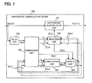
- FIG. 1 is a block diagram schematically showing the structure of a differential demodulation device 100 according to a first embodiment.
- the differential demodulation device 100 according to the first embodiment is structured to efficiently suppress the effects of noise and phase rotation by referring to reference signals during differential demodulation, and can maintain high demodulation performance even in a very noisy environment.
- the differential demodulation device 100 is also structured to reduce the effect of cumulative phase rotation in the received signal by successively generating a weighting coefficient according to the reliability of the received signal, in other words, to the result of a comparison between the received signal and the reference signals, and using the generated weighting coefficient to update the reference signals.
- the differential demodulation device 100 includes a differential demodulation unit 101, a delay unit 102, a comparison unit 103, a selection unit 104, a computation unit 105, and an update unit 106.
- the differential demodulation device 100 demodulates a differentially modulated signal, more specifically, an input signal X(m + 1) that is a modulated signal modulated by use of a differential angular shift modulation system, and outputs the result as an output signal Y(m + 1).
- the symbol ' m ' denotes a natural number equal to or greater than one and indicates the units of time in which signal processing is performed.
- the differential demodulation unit 101 uses the input signal X ( m + 1) and a comparison signal Z(m) to detect a phase difference, and outputs the detected phase difference as an output signal Y(m + 1). For example, the differential demodulation unit 101 detects the phase difference by a computation using the following equation (1).
- the symbol ⁇ A ⁇ denotes the argument of A, and B * denotes the complex conjugate signal of B.
- Y ⁇ m + 1 ⁇ X ⁇ m + 1 ⁇ Z * m
- the delay unit 102 delays the input signal by a prescribed time to obtain a delayed signal.
- the delay unit 102 supplies the obtained delayed signal to the comparison unit 103. For example, when the input signal X(m + 1) is received, the delay unit 102 outputs the input signal that preceded the input signal X(m + 1) as the delayed signal X(m). In this example, the delay unit 102 delays each input signal by the unit time in which a single input signal is processed.
- the comparison unit 103 compares the delayed signal X ( m ) with a reference signal S(m) including one or more reference element signals S k ( m ) , and computes physical quantities indicating the difference between the delayed signal X(m) and each reference element signal S k ( m ) as a first physical quantity D k ( m ) and a second physical quantity E k ( m ) .
- the comparison unit 103 supplies a first comparative signal D(m) indicating the first physical quantity D k ( m ) for each reference element signal S k ( m ) to the selection unit 104, and supplies a second comparative signal E(m) indicating the second physical quantity E k ( m ) for each reference element signal S k ( m ) to the computation unit 105.
- the symbol k denotes a natural number, and if the total number of signal points used in the digital angular modulation scheme is N, the range of k is preferably 1 ⁇ k ⁇ N.
- Each reference element signal is obtained by cumulative addition of weighted delayed signals, and preferably indicates one of the estimated candidates for a delayed signal having no noise component that is not correlated with the channel environment.
- the symbol ⁇ denotes the initial phase of S k (0) .
- the symbol j denotes the unit imaginary number.
- the initial values S k (0) of the reference element signals can be similarly determined.
- a specific exemplary method of updating the reference signal S(m) including one or more reference element signals S k ( m ) will be described below in the exemplary operation of the update unit 106.
- the initial values of the reference element signals are updated as described below and converge on a set of reference element signals adapted to the channel environment.
- the rate of convergence of the update process can be enhanced if the initial values of the reference element signals are the set of possible signal points of the modulated signal generated at the transmitting end in the wireless communication system.
- FIG. 2 is a schematic diagram showing examples of the first physical quantities D k ( m ) and the second physical quantities E k ( m ) .
- the comparison unit 103 can compute the Euclidean distance between the delayed signal X ( m ) and each reference element signal S k ( m ) as the first physical quantity D k ( m ).
- the comparison unit 103 collects the Euclidean distances computed in the range 1 ⁇ k ⁇ 4, and generates a first comparative signal D(m) indicating these Euclidean distances.
- the comparison unit 103 can also compute the Euclidean distance between the delayed signal X ( m ) and each reference element signal S k ( m ) as the second physical quantity E k ( m ) .
- the comparison unit 103 collects the Euclidean distances computed in the range 1 ⁇ k ⁇ 4, and generates a second comparative signal E(m) indicating these Euclidean distances.
- FIG. 3 is a schematic diagram showing other examples of the first physical quantities D k ( m ) and second physical quantities E k ( m ) .
- the comparison unit 103 can compute the phase difference between the delayed signal X(m) and each reference element signal S k ( m ) as the first physical quantity D k ( m ).
- the comparison unit 103 collects the phase differences computed in the range 1 ⁇ k ⁇ 4, and generates a first comparative signal D(m) indicating these phase differences.
- the comparison unit 103 can also compute the phase difference between the delayed signal X ( m ) and each reference element signal S k ( m ) as a second physical quantity E k ( m ) .
- the comparison unit 103 collects the phase differences computed in the range 1 ⁇ k ⁇ 4, and generates a second comparative signal E(m) indicating these phase differences.
- the first physical quantity D k ( m ), first comparative signal D(m), second physical quantity E k (m), and second comparative signal E(m) may be computed by using one of the methods shown in FIGs. 2 and 3 .
- the first physical quantity D k ( m ) and the first comparative signal D(m) may be computed by using one of the methods shown in FIGs. 2 and 3
- the second physical quantity E k ( m ) and the second comparative signal E(m) may be computed by using the other method shown in FIGs. 2 and 3 .
- first physical quantity D k ( m ), first comparative signal D(m), second physical quantity E k (m), and second comparative signal E(m) may be computed by using a method differing from the methods shown in FIGs. 2 and 3 .
- the comparison unit 103 supplies the delayed signal X ( m ) supplied from the delay unit 102 to the update unit 106.
- the selection unit 104 supplies the reference element signal S k ( m ) related to a single first physical quantity D k ( m ) selected from the first comparative signal D(m) on the basis of a predetermined selection rule to the differential demodulation unit 101 and update unit 106 as the comparison signal Z(m). For example, the selection unit 104 selects the first physical quantity D c ( m ) having the smallest absolute value from the set of the first physical quantities D k ( m ), and supplies the reference element signal S c ( m ) related the selected first physical quantity D c ( m ) to the differential demodulation unit 101 and update unit 106 as the comparison signal Z( m ).
- the symbol c denotes a natural number; the range of c is preferably 1 ⁇ c ⁇ N .
- the processing in the selection unit 104 described above can be represented by the following equations (2) and (3).
- the expression min ⁇ denotes the smallest of the values included within the braces.
- D c m min D 1 m , D 2 m , ... , D k m , ... , D N m
- Z m S c m
- the computation unit 105 calculates a weighting coefficient W ( m ) by using the second physical quantities E k ( m ) included in the second comparative signal E(m). For example, the computation unit 105 calculates a weighting coefficient W ( m ) that depends on the reliability of a single second physical quantity E k ( m ) selected from the set of N second physical quantities E k (m), or on a ratio of the reliability of this single second physical quantity E k ( m ) to the reliability of the N second physical quantities E k ( m ) .
- a weighting coefficient W ( m ) that depends on the reliability of a single second physical quantity E k ( m ) selected from the set of N second physical quantities E k (m), or on a ratio of the reliability of this single second physical quantity E k ( m ) to the reliability of the N second physical quantities E k ( m ) .
- the computation unit 105 may identify the second physical quantity E k ( m ) having the smallest absolute value in the set of N second physical quantities E k ( m ) as the smallest second physical quantity, and calculate a weighting coefficient W ( m ) proportional to the reciprocal of this smallest second physical quantity.
- the symbol A is a proportionality constant.
- the proportionality constant A affects the updating process. More specifically, the smaller the value of A is, the smaller the contribution ratio of the weighting coefficient W ( m ) to the updating of the reference signal S ( m ) becomes; the larger the value of A is, the larger the contribution ratio becomes.
- the value of the proportionality constant A may be selected arbitrarily on the basis of this contribution ratio.
- the computation unit 105 may identify the second physical quantity E k ( m ) having the smallest absolute value in the set of N second physical quantities E k ( m ) as the smallest second physical quantity, and calculate a weighting coefficient W ( m ) proportional to the ratio of the reciprocal of this smallest second physical quantity to the sum of the reciprocals of the N second physical quantities E k ( m ) .
- H 1 ( m ) denotes the harmonic mean of the N second physical quantities E k ( m ) .
- W m A ⁇ H 1 m ⁇ min E 1 m , E 2 m , ... , E k m , ... , E N m - 1 N
- the computation unit 105 may identify the second physical quantity E k ( m ) having the smallest absolute value in the set of N second physical quantities E k ( m ) as the smallest second physical quantity, and calculate a weighting coefficient W ( m ) proportional to the ratio of the reciprocal of this smallest second physical quantity to the sum of the reciprocals of i (1 ⁇ i ⁇ N ) of the N second physical quantities E k ( m ) .
- the above processing in the computation unit 105 can be represented by the following equation (6).
- the expression selmin ⁇ denotes the smallest of i values selected from the values included within the braces.
- the expression H 2 ( m ) denotes the harmonic mean of the i selected second physical quantities E k ( m ) .
- W m A ⁇ H 2 m ⁇ sel min E 1 m , E 2 m , ... , E k m , ... , E N m - 1 i
- the computation unit 105 can select the i (1 ⁇ i ⁇ N ) second physical quantities E k ( m ) by selecting second physical quantities E k ( m ) having absolute values equal to or less than a predetermined value (a third threshold value) from among the N second physical quantities E k ( m ) .
- Second physical quantities E k ( m ) having excessively large absolute values, in other words, an excessively large amount of error, can thereby be excluded, to reduce susceptibility to sudden bursts of noise and the like.
- the computation unit 105 may also calculate the weighting coefficient W(m) by using a method differing from equations (4), (5), and (6).
- the computation unit 105 supplies the calculated weighting coefficient W(m) to the update unit 106.
- the update unit 106 supplies the reference signal S(m) to the selection unit 104 and the comparison unit 103.
- the reference signal S(m) is used in the processing of input signal X(m + 1).
- the update unit 106 uses the weighting coefficient W ( m ) to update the reference signal S(m), thereby generating a reference signal S(m + 1).
- the reference signal S(m + 1) is used for processing the input signal X ( m + 2) received after input signal X ( m + 1).
- the update unit 106 computes an amplitude correction quantity and a phase correction quantity for updating the reference signal S ( m ).
- the update unit 106 shifts all the amplitudes and phases of all the reference element signals S k ( m ) included in the reference signal S(m) on the basis of the computed amplitude and phase correction quantities to update the reference signal S(m).
- the update unit 106 uses the weighting coefficient W ( m ), normalized so that 0 ⁇ W(m) ⁇ 1, to compute an amplitude correction quantity ⁇ ( m ) and a phase correction quantity ⁇ ( m ) by internally dividing a line segment including the signal point of the delayed signal X ( m ) and the signal point of the reference element signal S k ( m ) selected as the comparison signal Z(m) in the ratio of W ( m ):1 - W(m). More specifically, the update unit 106 can compute the amplitude correction quantity ⁇ ( m ) and the phase correction quantity ⁇ ( m ) by using the following equation (7).
- ) indicate absolute values.
- ⁇ m ⁇ m 1 - W m ⁇ Z m + W m ⁇ X m W m ⁇ Z m - ⁇ X m
- the update unit 106 updates the reference signal S(m) by using the following equations (8) and (9).
- ABS ⁇ denotes the absolute value of the value inside the braces.
- FIG. 4 is a schematic diagram showing the reference signal S(m) and the reference signal S(m + 1) generated by updating the reference signal S(m).
- the phase S k ( m + 1) is obtained by updating the phase S k ( m ) on the basis of the phase correction quantity ⁇ (m);
- the amplitude S k ( m + 1) is obtained by updating the amplitude S k ( m ) on the basis of the amplitude correction quantity ⁇ ( m ).
- the update unit 106 applies the same amplitude and phase corrections to all the reference element signals S k ( m ), the constellation of signal points of the updated reference element signals S k ( m + 1) remains similar to the constellation of signal points of the reference element signals S k ( m ) before the update.
- the above update process positions the signal point of the updated reference element signal S 1 ( m + 1) obtained by updating the reference element signal S 1 ( m ) selected as the comparison signal Z(m) between the signal point of reference element signal S 1 ( m ) and the signal point of the delayed signal X(m).
- the weighting coefficient W ( m ) increases in value, the delayed signal X ( m ) increases in reliability, so the signal point of the updated reference element signal S 1 ( m + 1) moves closer to the signal point of the delayed signal X ( m ).
- the update unit 106 may update the reference signal S(m) by using a method differing from the above method, provided the method applies equal amplitude and phase corrections to all the reference element signals S k ( m ) on the basis of the weighting coefficient W(m).
- the update unit 106 supplies the selection unit 104 and the comparison unit 103 with a predetermined signal: for example, a signal corresponding to an ideal set of signal points.
- FIG. 5 is a schematic diagram showing an exemplary constellation of the signal points of the input signal X ( m + 1), delayed signal X ( m ), and reference signal S(m) in a case in which QPSK is employed as the digital angular modulation scheme.
- phase angle P old ( m + 1) in FIG. 5 is an exemplary result obtained by use of this common conventional differential demodulation method. Because both the input signal X ( m + 1) and the delayed signal X(m) normally include thermal noise effects, there has been the problem that the DQPSK bit error rate is worse than the bit error rate for a QPSK signal, which uses an absolute phase reference.
- the reference element signal S k ( m ) closest to the delayed signal X(m) is selected as the comparison signal Z ( m ), and demodulation is carried out by taking the phase difference between the input signal X ( m + 1) and the comparison signal Z ( m ).
- the phase angle P new ( m + 1) in FIG. 5 is the demodulation result when the differential demodulation device 100 in the first embodiment is used.
- the reference element signal S k ( m ) in this example has been cumulatively corrected on the basis of the signals received in the past.
- an accurate reference signal S(m) can be obtained quickly and efficiently.
- the differential demodulation device 100 carries out differential demodulation by using, instead of the delayed signal X(m), a comparison signal Z(m) selected from a set of the reference element signals S k ( m ) in which the effects of thermal noise are reduced, a feature of the differential demodulation device 100 is that it can use a pseudo absolute phase reference. A resulting effect is that it can outperform the theoretical DQPSK bit error rate obtained in conventional differential demodulation. Another effect is also obtainable: cumulative correction of the reference element signal S k ( m ) further reduces the effects of thermal noise and can improve the bit error rate to a level equivalent to the theoretical QPSK bit error rate.
- the reference element signal S k ( m ) can track the temporal variations.
- the comparison signal Z ( m ) selected from the set of the reference element signals S k ( m ) therefore also tracks the variations in the channel environment, so that differential demodulation results in which the effects of noise and phase rotation are efficiently suppressed can be obtained.
- the differential demodulation device 100 uses a weighting coefficient responsive to the result of a comparison between the received signal and the reference signals to update the reference signals, and can refer to these reference signals during differential demodulation, even in a very noisy environment, that is, even when the receiving electric field strength is lower than the noise power, and even in a mobile channel in which phase rotation varies over time, the amount of phase rotation can be accurately detected, and high demodulation performance can be maintained.
- FIG. 6 is a block diagram schematically showing the structure of a differential demodulation device 200 according to a second embodiment.
- the differential demodulation device 200 includes a differential demodulation unit 101, a delay unit 202, a comparison unit 103, a selection unit 204, a computation unit 105, and an update unit 206.
- the differential demodulation device 200 according to the second embodiment differs from the differential demodulation device 100 according to the first embodiment in regard to processing in the delay unit 202, selection unit 204, and update unit 206.
- the delay unit 202 supplies the comparison unit 103 and selection unit 204 with a delayed input signal obtained by delaying the input signal by a prescribed time. For example, in FIG. 6 , when input signal X ( m + 1) is received, the delay unit 202 supplies the comparison unit 103 and selection unit 204 with the input signal that preceded input signal X ( m + 1) as the delayed signal X ( m ).
- the selection unit 204 selects, on the basis of a predetermined selection rule, either the delayed signal X ( m ) or the reference element signal S k ( m ) related to a single first physical quantity D k ( m ) selected from the first comparative signal D(m).
- the selection unit 204 makes this selection in response to an update difference indicated by a selection control signal F ( m ) supplied from the update unit 206, and supplies the selected signal to the differential demodulation unit 101 as the comparison signal Z ( m ).
- the selection unit 204 first selects the first physical quantity D c ( m ) having the smallest absolute value from the set of first physical quantities D k ( m ), and identifies the reference element signal S c ( m ) related to the selected first physical quantity D c ( m ). Next, if the update difference indicated by the selection control signal F ( m ) is equal to or less than a first predetermined value R 1 that functions as a first threshold, the selection unit 204 outputs this reference element signal S c ( m ) as the comparison signal Z ( m ). If the update difference indicated by the selection control signal F(m) is greater than the first predetermined value R 1 , the selection unit 204 outputs the delayed signal X ( m ) as the comparison signal Z ( m ).
- the method by which the selection unit 204 selects one of the delayed signal X ( m ) and the reference element signal S k ( m ) related to a single first physical quantity selected from the first comparative signal D(m), on the basis of a predetermined selection rule responsive to the value of the selection control signal F ( m ), may be a method other than the above.
- the update unit 206 takes, as the update difference, a difference obtained when reference signal S ( m - 1) is updated to generate reference signal S ( m ), and supplies the selection unit 204 with a selection control signal F(m) indicating this update difference.
- the update unit 206 can use either the Euclidean distance or the phase difference between reference signal S(m - 1) and reference signal S(m) as the update difference.
- the update unit 206 updates reference signal S(m) by use of weighting coefficient W(m) to generate reference signal S ( m + 1).
- the method described in the first embodiment may be used as the method of updating the reference signal S(m)
- a method differing from the method used in the first embodiment may be used, provided the method applies equal amplitude and phase corrections to all the reference element signals S k ( m ) on the basis of the weighting coefficient W(m).
- the differential demodulation device 200 uses a weighting coefficient responsive to the result of a comparison between the delayed signal and the reference signals, updates the reference signals, generates a selection control signal, adaptively chooses between the delayed signal and the reference signal on the basis of this selection control signal, and can use the selected signal as the comparison signal during differential demodulation, differential demodulation can be carried out with consideration of the stability of the reference signals, and demodulation performance can be further improved.
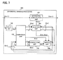
- FIG. 7 is a block diagram schematically showing the structure of a differential demodulation device 300 according to a third embodiment.
- the differential demodulation device 300 includes a differential demodulation unit 101, a delay unit 102, a comparison unit 103, a selection unit 304, a computation unit 105, and an update unit 306.
- the differential demodulation device 300 according to the third embodiment differs from the differential demodulation device 100 according to the first embodiment in regard to the processing in the selection unit 304 and update unit 306.
- the selection unit 304 supplies the differential demodulation unit 101 with the reference element signal S k ( m ) related to a single first physical quantity D k ( m ) selected from the first comparative signal D(m) on the basis of a predetermined selection rule as the comparison signal Z ( m ). For example, the selection unit 304 first selects the first physical quantity D c ( m ) having the smallest absolute value from the set of first physical quantities D k ( m ), and then outputs the reference element signal S c ( m ) related to the selected first physical quantity D c ( m ) as the comparison signal Z ( m ).
- the selection unit 304 supplies the update unit 306 with an update control signal G(m) indicating the magnitude of the comparison signal Z ( m ).
- the selection unit 304 generates an update control signal G ( m ) indicating the amplitude value or power value of the comparison signal Z ( m ), and supplies this update control signal G(m) to the update unit 306.
- the comparison signal Z ( m ) is not limited to these magnitude values, however.
- the method of computing the update control signal G(m) may be a method other than the above.
- the update unit 306 supplies the reference signal S(m) to the selection unit 304 and the comparison unit 103.
- the update unit 306 uses the weighting coefficient W ( m ) to update the reference signal S(m), thereby generating a reference signal S ( m + 1). For example, if the value indicated by the update control signal G(m) is equal to or less than a second predetermined value R 2 that functions as a second threshold, the update unit 306 shifts all the amplitudes and phases of the reference element signals S k ( m ) included in the reference signal S ( m ) by equal amounts on the basis of the weighting coefficient W ( m ) to update the reference signal S(m). When the update control signal G(m) is greater than the second predetermined value R 2 , the update unit 306 halts the updating of the reference signal S ( m ).
- the method of halting or resuming the updating of the reference signal S ( m ) is not limited to the method above, provided the method refers to the update control signal G(m).
- the content of the control scheme does not have to include halting and resumption of the update processing, provided the method refers to the update control signal G(m) to control the updating of the reference signal S(m).
- the differential demodulation device 300 uses a weighting coefficient responsive to the result of a comparison between the received signal and the reference signals to update the reference signals, refers to one of these reference signals as the comparison signal during differential demodulation, and can adaptively halt or resume updating of the reference signal on the basis of an update control signal obtained from this comparison signal, even if unexpected fluctuations in the received signal occur, the updating of the reference signals can be kept stable and demodulation performance can be further improved.
- FIG. 8 is a block diagram schematically showing the structure of a differential demodulation device 400 according to a fourth embodiment.
- the differential demodulation device 400 includes a differential demodulation unit 101, a delay unit 402, a comparison unit 103, a selection unit 404, a computation unit 105, and an update unit 406.
- the differential demodulation device 400 according to the fourth embodiment differs from the differential demodulation device 100 according to the first embodiment in regard to the processing in the delay unit 402, selection unit 404, and update unit 406.
- the delay unit 402 supplies the comparison unit 103 and selection unit 404 with a delayed input signal obtained by delaying the input signal by a prescribed time. For example, in FIG. 8 , when input signal X(m + 1) is received, the delay unit 402 supplies the comparison unit 103 and selection unit 404 with the input signal that preceded input signal X(m + 1) as the delayed signal X ( m ).
- the selection unit 404 selects, on the basis of a predetermined selection rule, either the delayed signal X ( m ) or the reference element signal S k ( m ) related to a single first physical quantity D k ( m ) selected from the first comparative signal D ( m ).
- the selection unit 404 makes this selection in response to an update difference indicated by a selection control signal F ( m ) supplied from the update unit 406, and supplies the selected signal to the differential demodulation unit 101 as the comparison signal Z(m).
- the selection unit 404 first selects the first physical quantity D c ( m ) having the smallest absolute value from the set of first physical quantities D k ( m ), and identifies the reference element signal S c ( m ) related to the selected first physical quantity D c ( m ). Next, if the update difference indicated by the selection control signal F(m) is equal to or less than a first predetermined value R 1 , the selection unit 404 outputs this reference element signal S c ( m ) as the comparison signal Z ( m ). If the update difference indicated by the selection control signal F(m) is greater than the first predetermined value R 1 , the selection unit 404 outputs the delayed signal X ( m ) as the comparison signal Z ( m ).
- the above processing in the selection unit 404 is represented by equations (2), (10), and (11).
- the selection unit 404 may use a method differing from the above to select one of the delayed signal X ( m ) and the reference element signal S k ( m ) related to a single first physical quantity selected from the first comparative signal D ( m ), on the basis of a predetermined selection rule responsive to the value of the selection control signal F(m).
- the selection unit 404 supplies the update unit 406 with an update control signal G(m) indicating the magnitude of the comparison signal Z ( m ).
- the selection unit 404 generates an update control signal G(m) indicating the amplitude value or power value of the comparison signal Z(m), and supplies this update control signal G(m) to the update unit 406.
- the comparison signal Z ( m ) is not limited to these magnitude values, however.
- the above processing in the selection unit 404 is represented by, for example, equations (2), (3), and (12).
- the method of computing the update control signal G ( m ) may also be a method other than the above.
- the reference signal S(m) is used in the processing of input signal X ( m + 1).
- the update unit 406 takes, as the update difference, a difference obtained when reference signal S(m - 1) is updated to generate reference signal S(m), and supplies the selection unit 404 with a selection control signal F ( m ) indicating this update difference.
- the update unit 406 can use either the Euclidean distance or the phase difference between the reference signal S ( m - 1) and the reference signal S ( m ) as the update difference.
- the update unit 406 uses the weighting coefficient W(m) to update the reference signal S ( m ), thereby generating a reference signal S ( m + 1). For example, if the value indicated by the update control signal G(m) is equal to or less than a second predetermined value R 2 , the update unit 406 shifts all the amplitudes and phases of the reference element signals S k ( m ) included in the reference signal S(m) by equal amounts on the basis of the weighting coefficient W(m) to update the reference signal S(m). When the update control signal G(m) is greater than the second predetermined value R 2 , the update unit 406 halts the updating of the reference signal S ( m ).
- the above processing in the update unit 406 is represented by, for example, equation (7) and equations (13) to (16).
- the method of halting or resuming the updating of the reference signal S(m) is not limited to the above, provided the method refers to the update control signal G ( m ).
- the content of the control scheme may differ from halting and resumption of the update processing, provided the method refers to the update control signal G ( m ) to control the updating of the reference signal S ( m ).
- the differential demodulation device 400 uses a weighting coefficient responsive to the result of a comparison between the received signal and the reference signals, updates the reference signals, generates a selection control signal, adaptively chooses between the delayed signal and the reference signal on the basis of this selection control signal, can use the selected signal as the comparison signal during differential demodulation, and can adaptively halt or resume updating of the reference signal on the basis of an update control signal obtained from this comparison signal, not only can differential demodulation be carried out in consideration of the stability of the reference signals, but in addition, even if unexpected fluctuations in the received signal occur, the updating of the reference signals can be kept stable and demodulation performance can be further improved.
- An exemplary aspect of the invention applicable to a differential demodulation device is described in the first to fourth embodiments above, but the invention is not limited to this aspect.
- the invention can be applied to a broadcast receiving device.
- 100, 200, 300, 400 differential demodulation device
- 101 differential demodulation unit
- 102, 202, 402 delay unit
- 103 comparison unit
- 104, 204, 304, 404 selection unit
- 105 computation unit
- 106, 206, 306, 406 update unit.
Landscapes
- Engineering & Computer Science (AREA)
- Computer Networks & Wireless Communication (AREA)
- Signal Processing (AREA)
- Digital Transmission Methods That Use Modulated Carrier Waves (AREA)
Abstract
Description
- The present invention relates to a differential demodulation device and a differential demodulation method.
- A problem in wireless communication systems that employ digital angular modulation is that the quality of the signal reaching the receiver can easily be degraded by multipath fading due to radio wave interference and sharp fluctuations in channel conditions due to motion. In addition, the reliability of the demodulated signal is low in weak electric field environments because the noise power rivals the received signal power.
- When QPSK (Quadrature Phase Shift Keying) is employed as the digital angular modulation scheme, for example, the received signal is generally demodulated by comparison with an absolute phase reference established on the phase plane. A problem is that when there is a large phase rotation of the received signal due to radio wave interference, motion, or thermal noise, accurate demodulation becomes theoretically impossible.
- DQPSK (Differential Quadrature Phase Shift Keying), which uses the phase difference in a QPSK signal to generate a new modulated signal, is widely and generally employed to mitigate the degradation of receiving performance caused by this problem.
- In DQPSK, the demodulated signal is generated by use of the phase difference between the signal received at a given time and the signal received immediately before the given time, so demodulation can be accurate even in an environment in which a fixed phase rotation is equally added to the received signal, i.e., a multipath fading environment. DQPSK enables accurate demodulation, with practically no influence of phase rotation, to be carried out even in a mobile reception environment in which the amount of phase rotation fluctuates with time, provided the rate of fluctuation is sufficiently less than the signal transmission rate.
- The signal received at a given time and the signal received immediately before the given time are both ordinarily affected by thermal noise, however, so there is the problem that the bit error rate in DQPSK is inferior to that of a QPSK signal which uses an absolute phase reference. This is shown in, for example,
Non-Patent Reference 1. - A contrasting technique disclosed in
Patent Reference 1 improves demodulation accuracy by estimating, from the signal received at the present time, the positions of all possible signal points that might appear in the digital phase modulation system being used and using the one signal point among the estimated signal points that is closest to the signal point of the signal received next. - Patent Reference 1: Japanese Patent Application Publication No.
5-176007 Fig. 1 ) - Non-Patent Reference 1: Yoichi Saito, Dejitaru Musen Tsushin no Henpukucho (Modulation and demodulation in digital wireless communication), Corona, February 1996, pp. 233-242
- The technique described in
Patent Reference 1 may fail to improve demodulation accuracy in a very noisy environment dominated by random amplitude and phase fluctuations due to noise, because the amount of phase rotation is estimated and compensated for by using only the signals received at a given instant and the next instant. - Furthermore, in the technique described in
Patent Reference 1, the reliability of the received signal is reduced in an environment in which the amount of phase rotation varies with time and varies at a rate that is comparable to the signal transmission rate, because then the demodulated signal can easily be affected by phase rotation. - It is therefore an object of the present invention to improve the reliability of the demodulated signal even in a channel environment in which the amplitude and phase of the received signal vary from one instant to the next and in an unfavorable channel environment in which the noise power rivals the received signal power.
- A differential demodulation device according to one aspect of the invention includes a delay unit for delaying an input signal by a prescribed time to obtain a delayed signal, a comparison unit for computing one or more physical quantities indicating differences between the delayed signal and one or more reference element signals, a selection unit for selecting, as a comparison signal, the reference element signal used in computing the one of the physical quantities having the smallest absolute value, and a differential demodulation unit for demodulating the input signal by use of the phase difference between the input signal and the comparison signal. Each of the reference element signals is updated with reference to at least some of the one or more physical quantities.
- According to one aspect of the invention, the reliability of the demodulated signal can be improved even in a channel environment in which the amplitude and phase of the received signal vary from one instant to the next and in an unfavorable channel environment in which the noise power rivals the received signal power.
-
-
FIG. 1 is a block diagram schematically showing the structure of a differential demodulation device according to a first embodiment. -
FIG. 2 is a schematic diagram showing examples of a first physical quantity and a second physical quantity in the first embodiment. -
FIG. 3 is a schematic diagram showing other examples of a first physical quantity and a second physical quantity in the first embodiment. -
FIG. 4 is a schematic diagram showing reference signals and reference signals generated by updating these reference signals in the first embodiment. -
FIG. 5 is a schematic diagram showing an exemplary constellation of the signal points of the input signal, delayed signal, and reference signals. -
FIG. 6 is a block diagram schematically showing the structure of a differential demodulation device according to a second embodiment. -
FIG. 7 is a block diagram schematically showing the structure of a differential demodulation device according to a third embodiment. -
FIG. 8 is a block diagram schematically showing the structure of a differential demodulation device according to a fourth embodiment. -
FIG. 1 is a block diagram schematically showing the structure of adifferential demodulation device 100 according to a first embodiment. Thedifferential demodulation device 100 according to the first embodiment is structured to efficiently suppress the effects of noise and phase rotation by referring to reference signals during differential demodulation, and can maintain high demodulation performance even in a very noisy environment. Thedifferential demodulation device 100 is also structured to reduce the effect of cumulative phase rotation in the received signal by successively generating a weighting coefficient according to the reliability of the received signal, in other words, to the result of a comparison between the received signal and the reference signals, and using the generated weighting coefficient to update the reference signals. - As shown in
FIG. 1 , thedifferential demodulation device 100 includes adifferential demodulation unit 101, adelay unit 102, acomparison unit 103, aselection unit 104, acomputation unit 105, and anupdate unit 106. Thedifferential demodulation device 100 demodulates a differentially modulated signal, more specifically, an input signal X(m + 1) that is a modulated signal modulated by use of a differential angular shift modulation system, and outputs the result as an output signal Y(m + 1). The symbol 'm' denotes a natural number equal to or greater than one and indicates the units of time in which signal processing is performed. - The
differential demodulation unit 101 uses the input signal X(m + 1) and a comparison signal Z(m) to detect a phase difference, and outputs the detected phase difference as an output signal Y(m + 1). For example, thedifferential demodulation unit 101 detects the phase difference by a computation using the following equation (1). The symbol ∠{ A} denotes the argument of A, and B* denotes the complex conjugate signal of B.
- The
delay unit 102 delays the input signal by a prescribed time to obtain a delayed signal. Thedelay unit 102 supplies the obtained delayed signal to thecomparison unit 103. For example, when the input signal X(m + 1) is received, thedelay unit 102 outputs the input signal that preceded the input signal X(m + 1) as the delayed signal X(m). In this example, thedelay unit 102 delays each input signal by the unit time in which a single input signal is processed. - The
comparison unit 103 compares the delayed signal X(m) with a reference signal S(m) including one or more reference element signals Sk (m), and computes physical quantities indicating the difference between the delayed signal X(m) and each reference element signal Sk (m) as a first physical quantity Dk (m) and a second physical quantity Ek (m). Thecomparison unit 103 supplies a first comparative signal D(m) indicating the first physical quantity Dk (m) for each reference element signal Sk (m) to theselection unit 104, and supplies a second comparative signal E(m) indicating the second physical quantity Ek (m) for each reference element signal Sk (m) to thecomputation unit 105. The symbol k denotes a natural number, and if the total number of signal points used in the digital angular modulation scheme is N, the range of k is preferably 1 ≤ k ≤ N. Each reference element signal is obtained by cumulative addition of weighted delayed signals, and preferably indicates one of the estimated candidates for a delayed signal having no noise component that is not correlated with the channel environment. - To take one specific example, when DBPSK (Differential Binary Phase Shift Keying) is employed as the digital angular modulation scheme, N = 2 and the initial values Sk (0) of the reference element signals included in the reference signal S(m) can be set as S 1(0) = 1 (θ = 0), and S2(0) = -1 (θ = π). The symbol θ denotes the initial phase of Sk (0). To take another example, when DQPSK is employed as the digital angular modulation scheme, N = 4 and the initial values Sk (0) of the reference element signals included in the reference signal S(m) can be set as S 1(0) = 1 + j (θ = π/4), S 2(0) = -1 + j (θ = 3π/4), S 3(0) = -1 - j (θ = 5π/4), and S4(0) = 1 - j (θ = 7π/4). The symbol j denotes the unit imaginary number. When digital angular modulation schemes other than the above are employed, the initial values Sk (0) of the reference element signals can be similarly determined. A specific exemplary method of updating the reference signal S(m) including one or more reference element signals Sk (m) will be described below in the exemplary operation of the
update unit 106. - If the number of initial values of the reference element signals is set equal to (or less than) the number of possible signal points of the modulated signal generated at the transmitting end in a wireless communication system, the initial values of the reference element signals are updated as described below and converge on a set of reference element signals adapted to the channel environment. The rate of convergence of the update process can be enhanced if the initial values of the reference element signals are the set of possible signal points of the modulated signal generated at the transmitting end in the wireless communication system.
-
FIG. 2 is a schematic diagram showing examples of the first physical quantities Dk (m) and the second physical quantities Ek (m). As shown inFIG. 2 , thecomparison unit 103 can compute the Euclidean distance between the delayed signal X(m) and each reference element signal Sk (m) as the first physical quantity Dk (m). Thecomparison unit 103 collects the Euclidean distances computed in therange 1 ≤ k ≤ 4, and generates a first comparative signal D(m) indicating these Euclidean distances. Thecomparison unit 103 can also compute the Euclidean distance between the delayed signal X(m) and each reference element signal Sk (m) as the second physical quantity Ek (m). Thecomparison unit 103 collects the Euclidean distances computed in therange 1 ≤ k ≤ 4, and generates a second comparative signal E(m) indicating these Euclidean distances. -
FIG. 3 is a schematic diagram showing other examples of the first physical quantities Dk (m) and second physical quantities Ek (m). As shown inFIG. 3 , thecomparison unit 103 can compute the phase difference between the delayed signal X(m) and each reference element signal Sk (m) as the first physical quantity Dk (m). Thecomparison unit 103 collects the phase differences computed in therange 1 ≤ k ≤ 4, and generates a first comparative signal D(m) indicating these phase differences. Thecomparison unit 103 can also compute the phase difference between the delayed signal X(m) and each reference element signal Sk (m) as a second physical quantity Ek (m). Thecomparison unit 103 collects the phase differences computed in therange 1 ≤ k ≤ 4, and generates a second comparative signal E(m) indicating these phase differences. - The first physical quantity Dk (m), first comparative signal D(m), second physical quantity Ek (m), and second comparative signal E(m) may be computed by using one of the methods shown in
FIGs. 2 and 3 . - Alternatively, the first physical quantity Dk (m) and the first comparative signal D(m) may be computed by using one of the methods shown in
FIGs. 2 and 3 , and the second physical quantity Ek (m) and the second comparative signal E(m) may be computed by using the other method shown inFIGs. 2 and 3 . - Furthermore, the first physical quantity Dk (m), first comparative signal D(m), second physical quantity Ek (m), and second comparative signal E(m) may be computed by using a method differing from the methods shown in
FIGs. 2 and 3 . - The
comparison unit 103 supplies the delayed signal X(m) supplied from thedelay unit 102 to theupdate unit 106. - The
selection unit 104 supplies the reference element signal Sk (m) related to a single first physical quantity Dk (m) selected from the first comparative signal D(m) on the basis of a predetermined selection rule to thedifferential demodulation unit 101 andupdate unit 106 as the comparison signal Z(m). For example, theselection unit 104 selects the first physical quantity Dc (m) having the smallest absolute value from the set of the first physical quantities Dk (m), and supplies the reference element signal Sc (m) related the selected first physical quantity Dc (m) to thedifferential demodulation unit 101 andupdate unit 106 as the comparison signal Z(m). The symbol c denotes a natural number; the range of c is preferably 1 ≤ c ≤ N. - The processing in the
selection unit 104 described above can be represented by the following equations (2) and (3). The expression min{} denotes the smallest of the values included within the braces.

- The
computation unit 105 calculates a weighting coefficient W(m) by using the second physical quantities Ek (m) included in the second comparative signal E(m). For example, thecomputation unit 105 calculates a weighting coefficient W(m) that depends on the reliability of a single second physical quantity Ek (m) selected from the set of N second physical quantities Ek (m), or on a ratio of the reliability of this single second physical quantity Ek (m) to the reliability of the N second physical quantities Ek (m). A specific description will be given below. - For example, the
computation unit 105 may identify the second physical quantity Ek (m) having the smallest absolute value in the set of N second physical quantities Ek (m) as the smallest second physical quantity, and calculate a weighting coefficient W(m) proportional to the reciprocal of this smallest second physical quantity. - The above processing in the
computation unit 105 can be represented by the following equation (4).
- The symbol A is a proportionality constant. When the
update unit 106 updates the reference signal S(m) by using the weighting coefficient W(m), the proportionality constant A affects the updating process. More specifically, the smaller the value of A is, the smaller the contribution ratio of the weighting coefficient W(m) to the updating of the reference signal S(m) becomes; the larger the value of A is, the larger the contribution ratio becomes. The value of the proportionality constant A may be selected arbitrarily on the basis of this contribution ratio. - As another example, the
computation unit 105 may identify the second physical quantity Ek (m) having the smallest absolute value in the set of N second physical quantities Ek (m) as the smallest second physical quantity, and calculate a weighting coefficient W(m) proportional to the ratio of the reciprocal of this smallest second physical quantity to the sum of the reciprocals of the N second physical quantities Ek (m). - The above processing in the
computation unit 105 can be represented by the following equation (5). The expression H 1(m) denotes the harmonic mean of the N second physical quantities Ek (m).
- As yet another example, the
computation unit 105 may identify the second physical quantity Ek (m) having the smallest absolute value in the set of N second physical quantities Ek (m) as the smallest second physical quantity, and calculate a weighting coefficient W(m) proportional to the ratio of the reciprocal of this smallest second physical quantity to the sum of the reciprocals of i (1 ≤ i ≤ N) of the N second physical quantities Ek (m). - The above processing in the
computation unit 105 can be represented by the following equation (6). The expression selmin{} denotes the smallest of i values selected from the values included within the braces. The expression H 2(m) denotes the harmonic mean of the i selected second physical quantities Ek (m).
- The
computation unit 105 can select the i (1 ≤ i ≤ N) second physical quantities Ek (m) by selecting second physical quantities Ek (m) having absolute values equal to or less than a predetermined value (a third threshold value) from among the N second physical quantities Ek (m). Second physical quantities Ek (m) having excessively large absolute values, in other words, an excessively large amount of error, can thereby be excluded, to reduce susceptibility to sudden bursts of noise and the like. - The
computation unit 105 may also calculate the weighting coefficient W(m) by using a method differing from equations (4), (5), and (6). - The
computation unit 105 supplies the calculated weighting coefficient W(m) to theupdate unit 106. - The
update unit 106 supplies the reference signal S(m) to theselection unit 104 and thecomparison unit 103. The reference signal S(m) is used in the processing of input signal X(m + 1). - The
update unit 106 uses the weighting coefficient W(m) to update the reference signal S(m), thereby generating a reference signal S(m + 1). The reference signal S(m + 1) is used for processing the input signal X(m + 2) received after input signal X(m + 1). For example, on the basis of the weighting coefficient W(m), theupdate unit 106 computes an amplitude correction quantity and a phase correction quantity for updating the reference signal S(m). Theupdate unit 106 shifts all the amplitudes and phases of all the reference element signals Sk (m) included in the reference signal S(m) on the basis of the computed amplitude and phase correction quantities to update the reference signal S(m). - For example, the
update unit 106 uses the weighting coefficient W(m), normalized so that 0 ≤ W(m) < 1, to compute an amplitude correction quantity α(m) and a phase correction quantity β(m) by internally dividing a line segment including the signal point of the delayed signal X(m) and the signal point of the reference element signal Sk (m) selected as the comparison signal Z(m) in the ratio of W(m):1 - W(m). More specifically, theupdate unit 106 can compute the amplitude correction quantity α(m) and the phase correction quantity β(m) by using the following equation (7). The vertical lines (| |) indicate absolute values.
- The
update unit 106 updates the reference signal S(m) by using the following equations (8) and (9). The expression ABS{} denotes the absolute value of the value inside the braces.

-
FIG. 4 is a schematic diagram showing the reference signal S(m) and the reference signal S(m + 1) generated by updating the reference signal S(m). As shown inFIG. 4 , the phase Sk (m + 1) is obtained by updating the phase Sk (m) on the basis of the phase correction quantity β(m); the amplitude Sk (m + 1) is obtained by updating the amplitude Sk (m) on the basis of the amplitude correction quantity α(m). Because theupdate unit 106 applies the same amplitude and phase corrections to all the reference element signals Sk (m), the constellation of signal points of the updated reference element signals Sk (m + 1) remains similar to the constellation of signal points of the reference element signals Sk (m) before the update. - The above update process positions the signal point of the updated reference element signal S 1(m + 1) obtained by updating the reference element signal S 1(m) selected as the comparison signal Z(m) between the signal point of reference element signal S 1(m) and the signal point of the delayed signal X(m). As the weighting coefficient W(m) increases in value, the delayed signal X(m) increases in reliability, so the signal point of the updated reference element signal S 1(m + 1) moves closer to the signal point of the delayed signal X(m).
- The
update unit 106 may update the reference signal S(m) by using a method differing from the above method, provided the method applies equal amplitude and phase corrections to all the reference element signals Sk (m) on the basis of the weighting coefficient W(m). As the initial value of the reference signal, theupdate unit 106 supplies theselection unit 104 and thecomparison unit 103 with a predetermined signal: for example, a signal corresponding to an ideal set of signal points. - Use of the above
differential demodulation device 100 makes it possible to generate the weighting coefficient W(m) according to the reliability of the received signal, to successively correct the reference signal S(m), and to maintain high demodulation performance by referring to this reference signal S(m) during differential demodulation. The effects obtained by employing the first embodiment will now be described with reference toFIG. 5 . -
FIG. 5 is a schematic diagram showing an exemplary constellation of the signal points of the input signal X(m + 1), delayed signal X(m), and reference signal S(m) in a case in which QPSK is employed as the digital angular modulation scheme. - In conventional differential demodulation, taking the phase difference between the input signal X(m + 1) and the delayed signal X(m) has been a common method. The phase angle Pold (m + 1) in
FIG. 5 is an exemplary result obtained by use of this common conventional differential demodulation method. Because both the input signal X(m + 1) and the delayed signal X(m) normally include thermal noise effects, there has been the problem that the DQPSK bit error rate is worse than the bit error rate for a QPSK signal, which uses an absolute phase reference. - When the
differential demodulation device 100 in the first embodiment is used, in contrast, the reference element signal Sk (m) closest to the delayed signal X(m) is selected as the comparison signal Z(m), and demodulation is carried out by taking the phase difference between the input signal X(m + 1) and the comparison signal Z(m). For example, the phase angle Pnew (m + 1) inFIG. 5 is the demodulation result when thedifferential demodulation device 100 in the first embodiment is used. The reference element signal Sk (m) in this example has been cumulatively corrected on the basis of the signals received in the past. Because a small weighting coefficient is applied to a received signal that is estimated to be strongly affected by noise and phase rotation, and a large weighting coefficient is applied to a received signal that is estimated to be close to the ideal demodulation point, an accurate reference signal S(m) can be obtained quickly and efficiently. - Because the
differential demodulation device 100 according to the first embodiment carries out differential demodulation by using, instead of the delayed signal X(m), a comparison signal Z(m) selected from a set of the reference element signals Sk (m) in which the effects of thermal noise are reduced, a feature of thedifferential demodulation device 100 is that it can use a pseudo absolute phase reference. A resulting effect is that it can outperform the theoretical DQPSK bit error rate obtained in conventional differential demodulation. Another effect is also obtainable: cumulative correction of the reference element signal Sk (m) further reduces the effects of thermal noise and can improve the bit error rate to a level equivalent to the theoretical QPSK bit error rate. - Even in a mobile channel environment in which the amount of phase rotation varies with time, according to the
differential demodulation device 100 in the first embodiment, the reference element signal Sk (m) can track the temporal variations. The comparison signal Z(m) selected from the set of the reference element signals Sk (m) therefore also tracks the variations in the channel environment, so that differential demodulation results in which the effects of noise and phase rotation are efficiently suppressed can be obtained. - As described above, because the
differential demodulation device 100 according to the first embodiment uses a weighting coefficient responsive to the result of a comparison between the received signal and the reference signals to update the reference signals, and can refer to these reference signals during differential demodulation, even in a very noisy environment, that is, even when the receiving electric field strength is lower than the noise power, and even in a mobile channel in which phase rotation varies over time, the amount of phase rotation can be accurately detected, and high demodulation performance can be maintained. -
FIG. 6 is a block diagram schematically showing the structure of adifferential demodulation device 200 according to a second embodiment. As shown inFIG. 6 , thedifferential demodulation device 200 includes adifferential demodulation unit 101, adelay unit 202, acomparison unit 103, aselection unit 204, acomputation unit 105, and anupdate unit 206. Thedifferential demodulation device 200 according to the second embodiment differs from thedifferential demodulation device 100 according to the first embodiment in regard to processing in thedelay unit 202,selection unit 204, andupdate unit 206. - As the delayed signal, the
delay unit 202 supplies thecomparison unit 103 andselection unit 204 with a delayed input signal obtained by delaying the input signal by a prescribed time. For example, inFIG. 6 , when input signal X(m + 1) is received, thedelay unit 202 supplies thecomparison unit 103 andselection unit 204 with the input signal that preceded input signal X(m + 1) as the delayed signal X(m). - The
selection unit 204 selects, on the basis of a predetermined selection rule, either the delayed signal X(m) or the reference element signal Sk (m) related to a single first physical quantity Dk (m) selected from the first comparative signal D(m). Theselection unit 204 makes this selection in response to an update difference indicated by a selection control signal F(m) supplied from theupdate unit 206, and supplies the selected signal to thedifferential demodulation unit 101 as the comparison signal Z(m). - For example, the
selection unit 204 first selects the first physical quantity Dc (m) having the smallest absolute value from the set of first physical quantities Dk (m), and identifies the reference element signal Sc (m) related to the selected first physical quantity Dc (m). Next, if the update difference indicated by the selection control signal F(m) is equal to or less than a first predetermined value R 1 that functions as a first threshold, theselection unit 204 outputs this reference element signal Sc (m) as the comparison signal Z(m). If the update difference indicated by the selection control signal F(m) is greater than the first predetermined value R 1, theselection unit 204 outputs the delayed signal X(m) as the comparison signal Z(m). - The above processing in the
selection unit 204 is represented by equation (2) and the following equations (10) and (11).

- The method by which the
selection unit 204 selects one of the delayed signal X(m) and the reference element signal Sk (m) related to a single first physical quantity selected from the first comparative signal D(m), on the basis of a predetermined selection rule responsive to the value of the selection control signal F(m), may be a method other than the above. - The
update unit 206 takes, as the update difference, a difference obtained when reference signal S(m - 1) is updated to generate reference signal S(m), and supplies theselection unit 204 with a selection control signal F(m) indicating this update difference. Theupdate unit 206 can use either the Euclidean distance or the phase difference between reference signal S(m - 1) and reference signal S(m) as the update difference. - Furthermore, the
update unit 206 updates reference signal S(m) by use of weighting coefficient W(m) to generate reference signal S(m + 1). Although the method described in the first embodiment may be used as the method of updating the reference signal S(m), a method differing from the method used in the first embodiment may be used, provided the method applies equal amplitude and phase corrections to all the reference element signals Sk (m) on the basis of the weighting coefficient W(m). - Because the
differential demodulation device 200 according to the second embodiment uses a weighting coefficient responsive to the result of a comparison between the delayed signal and the reference signals, updates the reference signals, generates a selection control signal, adaptively chooses between the delayed signal and the reference signal on the basis of this selection control signal, and can use the selected signal as the comparison signal during differential demodulation, differential demodulation can be carried out with consideration of the stability of the reference signals, and demodulation performance can be further improved. -
FIG. 7 is a block diagram schematically showing the structure of adifferential demodulation device 300 according to a third embodiment. As shown inFIG. 7 , thedifferential demodulation device 300 includes adifferential demodulation unit 101, adelay unit 102, acomparison unit 103, aselection unit 304, acomputation unit 105, and anupdate unit 306. Thedifferential demodulation device 300 according to the third embodiment differs from thedifferential demodulation device 100 according to the first embodiment in regard to the processing in theselection unit 304 andupdate unit 306. - The
selection unit 304 supplies thedifferential demodulation unit 101 with the reference element signal Sk (m) related to a single first physical quantity Dk (m) selected from the first comparative signal D(m) on the basis of a predetermined selection rule as the comparison signal Z(m). For example, theselection unit 304 first selects the first physical quantity Dc (m) having the smallest absolute value from the set of first physical quantities Dk (m), and then outputs the reference element signal Sc (m) related to the selected first physical quantity Dc (m) as the comparison signal Z(m). - The
selection unit 304 supplies theupdate unit 306 with an update control signal G(m) indicating the magnitude of the comparison signal Z(m). For example, theselection unit 304 generates an update control signal G(m) indicating the amplitude value or power value of the comparison signal Z(m), and supplies this update control signal G(m) to theupdate unit 306. The comparison signal Z(m) is not limited to these magnitude values, however. - The above processing in the
selection unit 304 is represented by, for example, equations (2) and (3) and the following equation (12).
- The method of computing the update control signal G(m) may be a method other than the above.
- The
update unit 306 supplies the reference signal S(m) to theselection unit 304 and thecomparison unit 103. - In response to the update control signal G(m), the
update unit 306 uses the weighting coefficient W(m) to update the reference signal S(m), thereby generating a reference signal S(m + 1). For example, if the value indicated by the update control signal G(m) is equal to or less than a second predetermined value R 2 that functions as a second threshold, theupdate unit 306 shifts all the amplitudes and phases of the reference element signals Sk (m) included in the reference signal S(m) by equal amounts on the basis of the weighting coefficient W(m) to update the reference signal S(m). When the update control signal G(m) is greater than the second predetermined value R 2, theupdate unit 306 halts the updating of the reference signal S(m). - The above processing in the
update unit 306 is represented by, for example, equation (7) and the following equations (13) to (16).


- The method of halting or resuming the updating of the reference signal S(m) is not limited to the method above, provided the method refers to the update control signal G(m). The content of the control scheme does not have to include halting and resumption of the update processing, provided the method refers to the update control signal G(m) to control the updating of the reference signal S(m).
- Because the
differential demodulation device 300 according to the third embodiment uses a weighting coefficient responsive to the result of a comparison between the received signal and the reference signals to update the reference signals, refers to one of these reference signals as the comparison signal during differential demodulation, and can adaptively halt or resume updating of the reference signal on the basis of an update control signal obtained from this comparison signal, even if unexpected fluctuations in the received signal occur, the updating of the reference signals can be kept stable and demodulation performance can be further improved. -
FIG. 8 is a block diagram schematically showing the structure of adifferential demodulation device 400 according to a fourth embodiment. As shown inFIG. 8 , thedifferential demodulation device 400 includes adifferential demodulation unit 101, adelay unit 402, acomparison unit 103, aselection unit 404, acomputation unit 105, and anupdate unit 406. Thedifferential demodulation device 400 according to the fourth embodiment differs from thedifferential demodulation device 100 according to the first embodiment in regard to the processing in thedelay unit 402,selection unit 404, andupdate unit 406. - As the delayed signal, the
delay unit 402 supplies thecomparison unit 103 andselection unit 404 with a delayed input signal obtained by delaying the input signal by a prescribed time. For example, inFIG. 8 , when input signal X(m + 1) is received, thedelay unit 402 supplies thecomparison unit 103 andselection unit 404 with the input signal that preceded input signal X(m + 1) as the delayed signal X(m). - The
selection unit 404 selects, on the basis of a predetermined selection rule, either the delayed signal X(m) or the reference element signal Sk (m) related to a single first physical quantity Dk (m) selected from the first comparative signal D(m). Theselection unit 404 makes this selection in response to an update difference indicated by a selection control signal F(m) supplied from theupdate unit 406, and supplies the selected signal to thedifferential demodulation unit 101 as the comparison signal Z(m). For example, theselection unit 404 first selects the first physical quantity Dc (m) having the smallest absolute value from the set of first physical quantities Dk (m), and identifies the reference element signal Sc (m) related to the selected first physical quantity Dc (m). Next, if the update difference indicated by the selection control signal F(m) is equal to or less than a first predetermined value R 1, theselection unit 404 outputs this reference element signal Sc (m) as the comparison signal Z(m). If the update difference indicated by the selection control signal F(m) is greater than the first predetermined value R 1, theselection unit 404 outputs the delayed signal X(m) as the comparison signal Z(m). The above processing in theselection unit 404 is represented by equations (2), (10), and (11). Alternatively, theselection unit 404 may use a method differing from the above to select one of the delayed signal X(m) and the reference element signal Sk (m) related to a single first physical quantity selected from the first comparative signal D(m), on the basis of a predetermined selection rule responsive to the value of the selection control signal F(m). - The
selection unit 404 supplies theupdate unit 406 with an update control signal G(m) indicating the magnitude of the comparison signal Z(m). For example, theselection unit 404 generates an update control signal G(m) indicating the amplitude value or power value of the comparison signal Z(m), and supplies this update control signal G(m) to theupdate unit 406. The comparison signal Z(m) is not limited to these magnitude values, however. The above processing in theselection unit 404 is represented by, for example, equations (2), (3), and (12). The method of computing the update control signal G(m) may also be a method other than the above. The reference signal S(m) is used in the processing of input signal X(m + 1). - The
update unit 406 takes, as the update difference, a difference obtained when reference signal S(m - 1) is updated to generate reference signal S(m), and supplies theselection unit 404 with a selection control signal F(m) indicating this update difference. Theupdate unit 406 can use either the Euclidean distance or the phase difference between the reference signal S(m - 1) and the reference signal S(m) as the update difference. - In response to the update control signal G(m), the
update unit 406 uses the weighting coefficient W(m) to update the reference signal S(m), thereby generating a reference signal S(m + 1). For example, if the value indicated by the update control signal G(m) is equal to or less than a second predetermined value R 2, theupdate unit 406 shifts all the amplitudes and phases of the reference element signals Sk (m) included in the reference signal S(m) by equal amounts on the basis of the weighting coefficient W(m) to update the reference signal S(m). When the update control signal G(m) is greater than the second predetermined value R 2, theupdate unit 406 halts the updating of the reference signal S(m). The above processing in theupdate unit 406 is represented by, for example, equation (7) and equations (13) to (16). - The method of halting or resuming the updating of the reference signal S(m) is not limited to the above, provided the method refers to the update control signal G(m). The content of the control scheme may differ from halting and resumption of the update processing, provided the method refers to the update control signal G(m) to control the updating of the reference signal S(m).
- Because the
differential demodulation device 400 according to the fourth embodiment uses a weighting coefficient responsive to the result of a comparison between the received signal and the reference signals, updates the reference signals, generates a selection control signal, adaptively chooses between the delayed signal and the reference signal on the basis of this selection control signal, can use the selected signal as the comparison signal during differential demodulation, and can adaptively halt or resume updating of the reference signal on the basis of an update control signal obtained from this comparison signal, not only can differential demodulation be carried out in consideration of the stability of the reference signals, but in addition, even if unexpected fluctuations in the received signal occur, the updating of the reference signals can be kept stable and demodulation performance can be further improved. - An exemplary aspect of the invention applicable to a differential demodulation device is described in the first to fourth embodiments above, but the invention is not limited to this aspect. For example, the invention can be applied to a broadcast receiving device.
- 100, 200, 300, 400: differential demodulation device, 101: differential demodulation unit, 102, 202, 402: delay unit, 103: comparison unit, 104, 204, 304, 404: selection unit, 105: computation unit, 106, 206, 306, 406: update unit.
Claims (22)
- A differential demodulation device comprising:a delay unit for delaying an input signal by a prescribed time to obtain a delayed signal;a comparison unit for computing one or more physical quantities indicating differences between the delayed signal and one or more reference element signals;a selection unit for selecting, as a comparison signal, the reference element signal used in computing one of the physical quantities having a smallest absolute value; anda differential demodulation unit for demodulating the input signal by use of a phase difference between the input signal and the comparison signal; whereineach of the reference element signals is updated with reference to at least some of the one or more physical quantities.
- The differential demodulation device of claim 1, wherein the comparison unit computes, as the physical quantities, at least one of a Euclidean distance and a phase difference between the delayed signal and the reference element signals.
- The differential demodulation device of claim 1 or 2, further comprising:a computation unit for using the at least one of the one or more physical quantities to calculate a weighting coefficient; andan update unit for using the weighting coefficient to update the one or more reference element signals.
- The differential demodulation device of claim 3, wherein the weighting coefficient is proportional to a reciprocal of the one of the physical quantities.
- The differential demodulation device of claim 3, wherein the weighting coefficient is proportional to a ratio of a reciprocal of the one of the physical quantities to a sum of all reciprocals of the one or more physical quantities.
- The differential demodulation device of claim 3, wherein the weighting coefficient is proportional to a ratio of a reciprocal of the one of the physical quantities to a sum of reciprocals of selected ones of the one or more physical quantities.
- The differential demodulation device of any one of claims 3 to 6, wherein the update unit updates the one or more reference element signals to position the signal point of the updated reference element signal obtained by updating the reference element signal corresponding to the comparison signal between the signal point of the delayed signal and the signal point of the comparison signal.
- The differential demodulation device of claim 7, wherein the update unit causes the signal point of the updated reference element signal obtained by updating the reference element signal corresponding to the comparison signal to approach the signal point of the delayed signal more closely as the weighting coefficient increases in value.
- The differential demodulation device of any one of claims 1 to 8, wherein the update unit computes an update difference indicating a difference between the reference element signal and the updated reference element signal, and
the selection unit:selects the reference element signal as the comparison signal when the update difference is equal to or less than a first threshold; andselects the delayed signal as the reference signal when the update difference is greater than the first threshold. - The differential demodulation device of any one of claims 3 to 8, wherein the update unit updates the reference element signals when the comparison signal has a magnitude equal to or less than a second threshold.
- The differential demodulation device of claim 10, wherein the update unit computes an update difference indicating a difference between the reference element signal and the updated reference element signal, and
the selection unit:selects the reference element signal as the comparison signal when the update difference is equal to or less than a first threshold; andselects the delayed signal as the reference signal when the update difference is equal to or greater than the first threshold. - A differential demodulation method, comprising:a delay step for delaying an input signal by a prescribed time to obtain a delayed signal;a comparison step for computing one or more physical quantities indicating differences between the delayed signal and one or more reference element signals;a selection step for selecting, as a comparison signal, the reference element signal used in computing one of the physical quantities having a smallest absolute value; anda differential demodulation step for demodulating the input signal by use of a phase difference between the input signal and the comparison signal; whereineach of the reference element signals is updated with reference to at least some of the one or more physical quantities.
- The differential demodulation method of claim 12, wherein the comparison step computes, as the physical quantities, at least one of a Euclidean distance and a phase difference between the delayed signal and the reference element signals.
- The differential demodulation method of claim 12 or 13, further comprising:a computation step for using the at least one of the one or more physical quantities to calculate a weighting coefficient; andan update step for using the weighting coefficient to update the one or more reference element signals.
- The differential demodulation method of claim 14, wherein the weighting coefficient is proportional to a reciprocal of the one of the physical quantities.
- The differential demodulation method of claim 14, wherein the weighting coefficient is proportional to a ratio of a reciprocal of the one of the physical quantities to a sum of all reciprocals of the one or more physical quantities.
- The differential demodulation method of claim 14, wherein the weighting coefficient is proportional to a ratio of a reciprocal of the one of the physical quantities to a sum of reciprocals of selected ones of the one or more physical quantities.
- The differential demodulation method of any one of claims 14 to 17, wherein the update step updates the one or more reference element signals to position the signal point of the updated reference element signal obtained by updating the reference element signal corresponding to the comparison signal between the signal point of the delayed signal and the signal point of the comparison signal.
- The differential demodulation method of claim 18, wherein the update step causes the signal point of the updated reference element signal obtained by updating the reference element signal corresponding to the comparison signal to approach the signal point of the delayed signal more closely as the weighting coefficient increases in value.
- The differential demodulation method of any one of claims 12 to 19, wherein the update step computes an update difference indicating a difference between the reference element signal and the updated reference element signal, and
the selection step:selects the reference element signal as the comparison signal when the update difference is equal to or less than a first threshold; andselects the delayed signal as the reference signal when the update difference is greater than the first threshold. - The differential demodulation method of any one of claims 14 to 19, wherein the update step updates the reference element signals when the comparison signal has a magnitude equal to or less than a second threshold.
- The differential demodulation method of claim 21, wherein the update step computes an update difference indicating a difference between the reference element signal and the updated reference element signal, and
the selection step:selects the reference element signal as the comparison signal when the update difference is equal to or less than a first threshold; andselects the delayed signal as the reference signal when the update difference is equal to or greater than the first threshold.
Applications Claiming Priority (2)
| Application Number | Priority Date | Filing Date | Title |
|---|---|---|---|
| JP2011106274 | 2011-05-11 | ||
| PCT/JP2012/053793 WO2012153556A1 (en) | 2011-05-11 | 2012-02-17 | Differential demodulation device and differential demodulation method |
Publications (3)
| Publication Number | Publication Date |
|---|---|
| EP2709329A1 true EP2709329A1 (en) | 2014-03-19 |
| EP2709329A4 EP2709329A4 (en) | 2014-10-22 |
| EP2709329B1 EP2709329B1 (en) | 2018-03-28 |
Family
ID=47139042
Family Applications (1)
| Application Number | Title | Priority Date | Filing Date |
|---|---|---|---|
| EP12782536.2A Not-in-force EP2709329B1 (en) | 2011-05-11 | 2012-02-17 | Device and corresponding method for differential demodulation |
Country Status (4)
| Country | Link |
|---|---|
| EP (1) | EP2709329B1 (en) |
| JP (1) | JP5599507B2 (en) |
| CN (1) | CN103460661B (en) |
| WO (1) | WO2012153556A1 (en) |
Cited By (1)
| Publication number | Priority date | Publication date | Assignee | Title |
|---|---|---|---|---|
| EP2930897A1 (en) * | 2014-04-10 | 2015-10-14 | Mitsubishi Electric Corporation | Differential demodulator and differential demodulation method |
Families Citing this family (2)
| Publication number | Priority date | Publication date | Assignee | Title |
|---|---|---|---|---|
| TWI604710B (en) * | 2016-04-29 | 2017-11-01 | 國立交通大學 | Qpsk demodulator |
| US11668585B2 (en) * | 2021-08-27 | 2023-06-06 | Stmicroelectronics S.R.L. | Method for correcting gyroscope demodulation phase drift |
Family Cites Families (8)
| Publication number | Priority date | Publication date | Assignee | Title |
|---|---|---|---|---|
| JPH05176007A (en) | 1991-12-20 | 1993-07-13 | Sony Corp | Demodulation device |
| JP3211112B2 (en) * | 1992-12-09 | 2001-09-25 | 日本電信電話株式会社 | DC drift compensation circuit |
| JPH07183831A (en) * | 1993-12-24 | 1995-07-21 | Sharp Corp | Digital communication method and digital communication device |
| JP3468657B2 (en) * | 1997-02-21 | 2003-11-17 | 松下電器産業株式会社 | Delay detector with error correction |
| JP3782237B2 (en) * | 1998-06-18 | 2006-06-07 | 日本放送協会 | OFDM signal demodulator |
| JP2006211211A (en) * | 2005-01-27 | 2006-08-10 | Matsushita Electric Ind Co Ltd | Data receiver |
| KR100649678B1 (en) * | 2005-07-15 | 2006-11-27 | 삼성전기주식회사 | Weighted Multiple Differential Demodulator |
| CN101366219A (en) * | 2006-03-06 | 2009-02-11 | 松下电器产业株式会社 | pulse radio receiver |
-
2012
- 2012-02-17 JP JP2013513950A patent/JP5599507B2/en not_active Expired - Fee Related
- 2012-02-17 WO PCT/JP2012/053793 patent/WO2012153556A1/en not_active Ceased
- 2012-02-17 CN CN201280014560.1A patent/CN103460661B/en not_active Expired - Fee Related
- 2012-02-17 EP EP12782536.2A patent/EP2709329B1/en not_active Not-in-force
Cited By (4)
| Publication number | Priority date | Publication date | Assignee | Title |
|---|---|---|---|---|
| EP2930897A1 (en) * | 2014-04-10 | 2015-10-14 | Mitsubishi Electric Corporation | Differential demodulator and differential demodulation method |
| CN104980387A (en) * | 2014-04-10 | 2015-10-14 | 三菱电机株式会社 | Differential demodulator and differential demodulation method |
| JP2015201810A (en) * | 2014-04-10 | 2015-11-12 | 三菱電機株式会社 | Differential demodulation apparatus and differential demodulation method |
| CN104980387B (en) * | 2014-04-10 | 2018-05-08 | 三菱电机株式会社 | Differential ference spiral device and differential ference spiral method |
Also Published As
| Publication number | Publication date |
|---|---|
| CN103460661A (en) | 2013-12-18 |
| WO2012153556A1 (en) | 2012-11-15 |
| EP2709329A4 (en) | 2014-10-22 |
| CN103460661B (en) | 2016-05-11 |
| JP5599507B2 (en) | 2014-10-01 |
| EP2709329B1 (en) | 2018-03-28 |
| JPWO2012153556A1 (en) | 2014-07-31 |
Similar Documents
| Publication | Publication Date | Title |
|---|---|---|
| US7313086B2 (en) | OFDM receiver, semiconductor integrated circuit and OFDM method for receiving a signal | |
| CN105245303B (en) | A kind of high-speed burst demodulation synchronization system | |
| US6628926B1 (en) | Method for automatic frequency control | |
| US20030128660A1 (en) | OFDM communications apparatus, OFDM communications method, and OFDM communications program | |
| US6404827B1 (en) | Method and apparatus for linear predicting | |
| EP2656566B1 (en) | Automatic frequency offset compensation in zero-intermediate frequency receivers using minimum-shift keying (msk) signaling | |
| US7139333B2 (en) | Frequency error estimating receiver, and frequency error estimating method | |
| JP3872950B2 (en) | Frequency division multiplex transmission signal receiver | |
| WO2000054431A1 (en) | Estimation of doppler shift compensation in a mobile communication system | |
| EP2822245B1 (en) | Radio transmission device, radio reception device and data transmission method | |
| WO2013001474A1 (en) | Estimation of frequency offset between a base station and mobile terminal | |
| EP2709329B1 (en) | Device and corresponding method for differential demodulation | |
| US20230283505A1 (en) | Frequency offset estimation | |
| CN101490660A (en) | CORDIC processor with improved accuracy | |
| US20170180182A1 (en) | Joint noncoherent demodulation and carrier frequency offset correction based on non-linear filtering | |
| US6381290B1 (en) | Mobile unit for pilot symbol assisted wireless system and method of improving performance thereof | |
| US8340230B2 (en) | Receiving device, receiving method, and program | |
| CN109756435B (en) | Method for estimating frequency offset of signal | |
| US10476731B2 (en) | Joint noncoherent demodulation and carrier frequency offset correction based on non-linear filtering | |
| US20040252795A1 (en) | Frequency offset detection processing system and frequency offset detection processing method using the same | |
| CN111064685A (en) | Carrier synchronization method, device and equipment | |
| JP3321371B2 (en) | Frequency offset compensator | |
| JP3355147B2 (en) | Automatic frequency control method | |
| KR101418471B1 (en) | Apparatus for compensating frequency offset | |
| JPH11112591A (en) | Automatic frequency control method |
Legal Events
| Date | Code | Title | Description |
|---|---|---|---|
| PUAI | Public reference made under article 153(3) epc to a published international application that has entered the european phase |
Free format text: ORIGINAL CODE: 0009012 |
|
| 17P | Request for examination filed |
Effective date: 20130722 |
|
| AK | Designated contracting states |
Kind code of ref document: A1 Designated state(s): AL AT BE BG CH CY CZ DE DK EE ES FI FR GB GR HR HU IE IS IT LI LT LU LV MC MK MT NL NO PL PT RO RS SE SI SK SM TR |
|
| DAX | Request for extension of the european patent (deleted) | ||
| REG | Reference to a national code |
Ref country code: DE Ref legal event code: R079 Ref document number: 602012044513 Country of ref document: DE Free format text: PREVIOUS MAIN CLASS: H04L0027220000 Ipc: H04L0027233000 |
|
| A4 | Supplementary search report drawn up and despatched |
Effective date: 20140922 |
|
| RIC1 | Information provided on ipc code assigned before grant |
Ipc: H04L 27/233 20060101AFI20140916BHEP |
|
| GRAP | Despatch of communication of intention to grant a patent |
Free format text: ORIGINAL CODE: EPIDOSNIGR1 |
|
| STAA | Information on the status of an ep patent application or granted ep patent |
Free format text: STATUS: GRANT OF PATENT IS INTENDED |
|
| GRAJ | Information related to disapproval of communication of intention to grant by the applicant or resumption of examination proceedings by the epo deleted |
Free format text: ORIGINAL CODE: EPIDOSDIGR1 |
|
| GRAP | Despatch of communication of intention to grant a patent |
Free format text: ORIGINAL CODE: EPIDOSNIGR1 |
|
| INTG | Intention to grant announced |
Effective date: 20171012 |
|
| INTG | Intention to grant announced |
Effective date: 20171024 |
|
| GRAS | Grant fee paid |
Free format text: ORIGINAL CODE: EPIDOSNIGR3 |
|
| GRAJ | Information related to disapproval of communication of intention to grant by the applicant or resumption of examination proceedings by the epo deleted |
Free format text: ORIGINAL CODE: EPIDOSDIGR1 |
|
| GRAL | Information related to payment of fee for publishing/printing deleted |
Free format text: ORIGINAL CODE: EPIDOSDIGR3 |
|
| STAA | Information on the status of an ep patent application or granted ep patent |
Free format text: STATUS: REQUEST FOR EXAMINATION WAS MADE |
|
| GRAR | Information related to intention to grant a patent recorded |
Free format text: ORIGINAL CODE: EPIDOSNIGR71 |
|
| STAA | Information on the status of an ep patent application or granted ep patent |
Free format text: STATUS: GRANT OF PATENT IS INTENDED |
|
| GRAA | (expected) grant |
Free format text: ORIGINAL CODE: 0009210 |
|
| STAA | Information on the status of an ep patent application or granted ep patent |
Free format text: STATUS: THE PATENT HAS BEEN GRANTED |
|
| INTC | Intention to grant announced (deleted) | ||
| INTG | Intention to grant announced |
Effective date: 20180201 |
|
| AK | Designated contracting states |
Kind code of ref document: B1 Designated state(s): AL AT BE BG CH CY CZ DE DK EE ES FI FR GB GR HR HU IE IS IT LI LT LU LV MC MK MT NL NO PL PT RO RS SE SI SK SM TR |
|
| REG | Reference to a national code |
Ref country code: GB Ref legal event code: FG4D |
|
| REG | Reference to a national code |
Ref country code: CH Ref legal event code: EP |
|
| REG | Reference to a national code |
Ref country code: AT Ref legal event code: REF Ref document number: 984375 Country of ref document: AT Kind code of ref document: T Effective date: 20180415 |
|
| REG | Reference to a national code |
Ref country code: IE Ref legal event code: FG4D |
|
| REG | Reference to a national code |
Ref country code: DE Ref legal event code: R096 Ref document number: 602012044513 Country of ref document: DE |
|
| PG25 | Lapsed in a contracting state [announced via postgrant information from national office to epo] |
Ref country code: LT Free format text: LAPSE BECAUSE OF FAILURE TO SUBMIT A TRANSLATION OF THE DESCRIPTION OR TO PAY THE FEE WITHIN THE PRESCRIBED TIME-LIMIT Effective date: 20180328 Ref country code: HR Free format text: LAPSE BECAUSE OF FAILURE TO SUBMIT A TRANSLATION OF THE DESCRIPTION OR TO PAY THE FEE WITHIN THE PRESCRIBED TIME-LIMIT Effective date: 20180328 Ref country code: NO Free format text: LAPSE BECAUSE OF FAILURE TO SUBMIT A TRANSLATION OF THE DESCRIPTION OR TO PAY THE FEE WITHIN THE PRESCRIBED TIME-LIMIT Effective date: 20180628 Ref country code: FI Free format text: LAPSE BECAUSE OF FAILURE TO SUBMIT A TRANSLATION OF THE DESCRIPTION OR TO PAY THE FEE WITHIN THE PRESCRIBED TIME-LIMIT Effective date: 20180328 |
|
| REG | Reference to a national code |
Ref country code: NL Ref legal event code: MP Effective date: 20180328 |
|
| REG | Reference to a national code |
Ref country code: LT Ref legal event code: MG4D |
|
| PG25 | Lapsed in a contracting state [announced via postgrant information from national office to epo] |
Ref country code: GR Free format text: LAPSE BECAUSE OF FAILURE TO SUBMIT A TRANSLATION OF THE DESCRIPTION OR TO PAY THE FEE WITHIN THE PRESCRIBED TIME-LIMIT Effective date: 20180629 Ref country code: LV Free format text: LAPSE BECAUSE OF FAILURE TO SUBMIT A TRANSLATION OF THE DESCRIPTION OR TO PAY THE FEE WITHIN THE PRESCRIBED TIME-LIMIT Effective date: 20180328 Ref country code: SE Free format text: LAPSE BECAUSE OF FAILURE TO SUBMIT A TRANSLATION OF THE DESCRIPTION OR TO PAY THE FEE WITHIN THE PRESCRIBED TIME-LIMIT Effective date: 20180328 Ref country code: BG Free format text: LAPSE BECAUSE OF FAILURE TO SUBMIT A TRANSLATION OF THE DESCRIPTION OR TO PAY THE FEE WITHIN THE PRESCRIBED TIME-LIMIT Effective date: 20180628 Ref country code: RS Free format text: LAPSE BECAUSE OF FAILURE TO SUBMIT A TRANSLATION OF THE DESCRIPTION OR TO PAY THE FEE WITHIN THE PRESCRIBED TIME-LIMIT Effective date: 20180328 |
|
| PG25 | Lapsed in a contracting state [announced via postgrant information from national office to epo] |
Ref country code: PL Free format text: LAPSE BECAUSE OF FAILURE TO SUBMIT A TRANSLATION OF THE DESCRIPTION OR TO PAY THE FEE WITHIN THE PRESCRIBED TIME-LIMIT Effective date: 20180328 Ref country code: AL Free format text: LAPSE BECAUSE OF FAILURE TO SUBMIT A TRANSLATION OF THE DESCRIPTION OR TO PAY THE FEE WITHIN THE PRESCRIBED TIME-LIMIT Effective date: 20180328 Ref country code: ES Free format text: LAPSE BECAUSE OF FAILURE TO SUBMIT A TRANSLATION OF THE DESCRIPTION OR TO PAY THE FEE WITHIN THE PRESCRIBED TIME-LIMIT Effective date: 20180328 Ref country code: EE Free format text: LAPSE BECAUSE OF FAILURE TO SUBMIT A TRANSLATION OF THE DESCRIPTION OR TO PAY THE FEE WITHIN THE PRESCRIBED TIME-LIMIT Effective date: 20180328 Ref country code: NL Free format text: LAPSE BECAUSE OF FAILURE TO SUBMIT A TRANSLATION OF THE DESCRIPTION OR TO PAY THE FEE WITHIN THE PRESCRIBED TIME-LIMIT Effective date: 20180328 Ref country code: RO Free format text: LAPSE BECAUSE OF FAILURE TO SUBMIT A TRANSLATION OF THE DESCRIPTION OR TO PAY THE FEE WITHIN THE PRESCRIBED TIME-LIMIT Effective date: 20180328 |
|
| PG25 | Lapsed in a contracting state [announced via postgrant information from national office to epo] |
Ref country code: SM Free format text: LAPSE BECAUSE OF FAILURE TO SUBMIT A TRANSLATION OF THE DESCRIPTION OR TO PAY THE FEE WITHIN THE PRESCRIBED TIME-LIMIT Effective date: 20180328 Ref country code: CZ Free format text: LAPSE BECAUSE OF FAILURE TO SUBMIT A TRANSLATION OF THE DESCRIPTION OR TO PAY THE FEE WITHIN THE PRESCRIBED TIME-LIMIT Effective date: 20180328 Ref country code: SK Free format text: LAPSE BECAUSE OF FAILURE TO SUBMIT A TRANSLATION OF THE DESCRIPTION OR TO PAY THE FEE WITHIN THE PRESCRIBED TIME-LIMIT Effective date: 20180328 |
|
| REG | Reference to a national code |
Ref country code: AT Ref legal event code: MK05 Ref document number: 984375 Country of ref document: AT Kind code of ref document: T Effective date: 20180328 |
|
| PG25 | Lapsed in a contracting state [announced via postgrant information from national office to epo] |
Ref country code: PT Free format text: LAPSE BECAUSE OF FAILURE TO SUBMIT A TRANSLATION OF THE DESCRIPTION OR TO PAY THE FEE WITHIN THE PRESCRIBED TIME-LIMIT Effective date: 20180730 |
|
| REG | Reference to a national code |
Ref country code: DE Ref legal event code: R097 Ref document number: 602012044513 Country of ref document: DE |
|
| PG25 | Lapsed in a contracting state [announced via postgrant information from national office to epo] |
Ref country code: AT Free format text: LAPSE BECAUSE OF FAILURE TO SUBMIT A TRANSLATION OF THE DESCRIPTION OR TO PAY THE FEE WITHIN THE PRESCRIBED TIME-LIMIT Effective date: 20180328 Ref country code: DK Free format text: LAPSE BECAUSE OF FAILURE TO SUBMIT A TRANSLATION OF THE DESCRIPTION OR TO PAY THE FEE WITHIN THE PRESCRIBED TIME-LIMIT Effective date: 20180328 |
|
| PLBE | No opposition filed within time limit |
Free format text: ORIGINAL CODE: 0009261 |
|
| STAA | Information on the status of an ep patent application or granted ep patent |
Free format text: STATUS: NO OPPOSITION FILED WITHIN TIME LIMIT |
|
| PG25 | Lapsed in a contracting state [announced via postgrant information from national office to epo] |
Ref country code: IT Free format text: LAPSE BECAUSE OF FAILURE TO SUBMIT A TRANSLATION OF THE DESCRIPTION OR TO PAY THE FEE WITHIN THE PRESCRIBED TIME-LIMIT Effective date: 20180328 |
|
| 26N | No opposition filed |
Effective date: 20190103 |
|
| PG25 | Lapsed in a contracting state [announced via postgrant information from national office to epo] |
Ref country code: SI Free format text: LAPSE BECAUSE OF FAILURE TO SUBMIT A TRANSLATION OF THE DESCRIPTION OR TO PAY THE FEE WITHIN THE PRESCRIBED TIME-LIMIT Effective date: 20180328 |
|
| REG | Reference to a national code |
Ref country code: CH Ref legal event code: PL |
|
| GBPC | Gb: european patent ceased through non-payment of renewal fee |
Effective date: 20190217 |
|
| PG25 | Lapsed in a contracting state [announced via postgrant information from national office to epo] |
Ref country code: LU Free format text: LAPSE BECAUSE OF NON-PAYMENT OF DUE FEES Effective date: 20190217 Ref country code: MC Free format text: LAPSE BECAUSE OF FAILURE TO SUBMIT A TRANSLATION OF THE DESCRIPTION OR TO PAY THE FEE WITHIN THE PRESCRIBED TIME-LIMIT Effective date: 20180328 |
|
| REG | Reference to a national code |
Ref country code: BE Ref legal event code: MM Effective date: 20190228 |
|
| REG | Reference to a national code |
Ref country code: IE Ref legal event code: MM4A |
|
| PG25 | Lapsed in a contracting state [announced via postgrant information from national office to epo] |
Ref country code: LI Free format text: LAPSE BECAUSE OF NON-PAYMENT OF DUE FEES Effective date: 20190228 Ref country code: CH Free format text: LAPSE BECAUSE OF NON-PAYMENT OF DUE FEES Effective date: 20190228 |
|
| PG25 | Lapsed in a contracting state [announced via postgrant information from national office to epo] |
Ref country code: GB Free format text: LAPSE BECAUSE OF NON-PAYMENT OF DUE FEES Effective date: 20190217 Ref country code: IE Free format text: LAPSE BECAUSE OF NON-PAYMENT OF DUE FEES Effective date: 20190217 |
|
| PG25 | Lapsed in a contracting state [announced via postgrant information from national office to epo] |
Ref country code: BE Free format text: LAPSE BECAUSE OF NON-PAYMENT OF DUE FEES Effective date: 20190228 Ref country code: FR Free format text: LAPSE BECAUSE OF NON-PAYMENT OF DUE FEES Effective date: 20190228 |
|
| PG25 | Lapsed in a contracting state [announced via postgrant information from national office to epo] |
Ref country code: TR Free format text: LAPSE BECAUSE OF FAILURE TO SUBMIT A TRANSLATION OF THE DESCRIPTION OR TO PAY THE FEE WITHIN THE PRESCRIBED TIME-LIMIT Effective date: 20180328 |
|
| PG25 | Lapsed in a contracting state [announced via postgrant information from national office to epo] |
Ref country code: MT Free format text: LAPSE BECAUSE OF NON-PAYMENT OF DUE FEES Effective date: 20190217 |
|
| REG | Reference to a national code |
Ref country code: DE Ref legal event code: R084 Ref document number: 602012044513 Country of ref document: DE |
|
| PG25 | Lapsed in a contracting state [announced via postgrant information from national office to epo] |
Ref country code: CY Free format text: LAPSE BECAUSE OF FAILURE TO SUBMIT A TRANSLATION OF THE DESCRIPTION OR TO PAY THE FEE WITHIN THE PRESCRIBED TIME-LIMIT Effective date: 20180328 |
|
| PG25 | Lapsed in a contracting state [announced via postgrant information from national office to epo] |
Ref country code: IS Free format text: LAPSE BECAUSE OF FAILURE TO SUBMIT A TRANSLATION OF THE DESCRIPTION OR TO PAY THE FEE WITHIN THE PRESCRIBED TIME-LIMIT Effective date: 20180728 |
|
| PG25 | Lapsed in a contracting state [announced via postgrant information from national office to epo] |
Ref country code: HU Free format text: LAPSE BECAUSE OF FAILURE TO SUBMIT A TRANSLATION OF THE DESCRIPTION OR TO PAY THE FEE WITHIN THE PRESCRIBED TIME-LIMIT; INVALID AB INITIO Effective date: 20120217 |
|
| PG25 | Lapsed in a contracting state [announced via postgrant information from national office to epo] |
Ref country code: MK Free format text: LAPSE BECAUSE OF FAILURE TO SUBMIT A TRANSLATION OF THE DESCRIPTION OR TO PAY THE FEE WITHIN THE PRESCRIBED TIME-LIMIT Effective date: 20180328 |
|
| P01 | Opt-out of the competence of the unified patent court (upc) registered |
Effective date: 20230512 |
|
| PGFP | Annual fee paid to national office [announced via postgrant information from national office to epo] |
Ref country code: DE Payment date: 20231228 Year of fee payment: 13 |
|
| REG | Reference to a national code |
Ref country code: DE Ref legal event code: R119 Ref document number: 602012044513 Country of ref document: DE |
|
| PG25 | Lapsed in a contracting state [announced via postgrant information from national office to epo] |
Ref country code: DE Free format text: LAPSE BECAUSE OF NON-PAYMENT OF DUE FEES Effective date: 20250902 |