EP2709218A2 - Stabilized pump laser output system and method - Google Patents
Stabilized pump laser output system and method Download PDFInfo
- Publication number
- EP2709218A2 EP2709218A2 EP20130181882 EP13181882A EP2709218A2 EP 2709218 A2 EP2709218 A2 EP 2709218A2 EP 20130181882 EP20130181882 EP 20130181882 EP 13181882 A EP13181882 A EP 13181882A EP 2709218 A2 EP2709218 A2 EP 2709218A2
- Authority
- EP
- European Patent Office
- Prior art keywords
- fiber
- light source
- output signal
- bragg grating
- propagation
- Prior art date
- Legal status (The legal status is an assumption and is not a legal conclusion. Google has not performed a legal analysis and makes no representation as to the accuracy of the status listed.)
- Granted
Links
- 238000000034 method Methods 0.000 title claims description 28
- 239000000835 fiber Substances 0.000 claims abstract description 111
- 230000001427 coherent effect Effects 0.000 claims abstract description 34
- 239000013307 optical fiber Substances 0.000 claims abstract description 30
- 239000000758 substrate Substances 0.000 claims abstract description 18
- 239000004611 light stabiliser Substances 0.000 claims abstract description 16
- 239000000463 material Substances 0.000 claims description 11
- 238000005530 etching Methods 0.000 claims description 8
- 239000003381 stabilizer Substances 0.000 claims description 8
- 230000008878 coupling Effects 0.000 claims description 6
- 238000010168 coupling process Methods 0.000 claims description 6
- 238000005859 coupling reaction Methods 0.000 claims description 6
- 230000010287 polarization Effects 0.000 abstract description 10
- 230000008033 biological extinction Effects 0.000 abstract description 4
- 239000004065 semiconductor Substances 0.000 abstract 1
- 230000003287 optical effect Effects 0.000 description 22
- 230000005540 biological transmission Effects 0.000 description 6
- 238000001816 cooling Methods 0.000 description 6
- 238000010586 diagram Methods 0.000 description 5
- 238000004891 communication Methods 0.000 description 4
- FOXXZZGDIAQPQI-XKNYDFJKSA-N Asp-Pro-Ser-Ser Chemical compound OC(=O)C[C@H](N)C(=O)N1CCC[C@H]1C(=O)N[C@@H](CO)C(=O)N[C@@H](CO)C(O)=O FOXXZZGDIAQPQI-XKNYDFJKSA-N 0.000 description 3
- 230000015556 catabolic process Effects 0.000 description 3
- 238000006731 degradation reaction Methods 0.000 description 3
- 230000009467 reduction Effects 0.000 description 3
- 230000001419 dependent effect Effects 0.000 description 2
- 230000005281 excited state Effects 0.000 description 2
- 230000000873 masking effect Effects 0.000 description 2
- 239000002245 particle Substances 0.000 description 2
- 230000000737 periodic effect Effects 0.000 description 2
- 230000008569 process Effects 0.000 description 2
- 238000012546 transfer Methods 0.000 description 2
- 229910000980 Aluminium gallium arsenide Inorganic materials 0.000 description 1
- 229910000530 Gallium indium arsenide Inorganic materials 0.000 description 1
- 230000005679 Peltier effect Effects 0.000 description 1
- VYPSYNLAJGMNEJ-UHFFFAOYSA-N Silicium dioxide Chemical group O=[Si]=O VYPSYNLAJGMNEJ-UHFFFAOYSA-N 0.000 description 1
- 235000005811 Viola adunca Nutrition 0.000 description 1
- 240000009038 Viola odorata Species 0.000 description 1
- 235000013487 Viola odorata Nutrition 0.000 description 1
- 235000002254 Viola papilionacea Nutrition 0.000 description 1
- 230000004075 alteration Effects 0.000 description 1
- 230000008859 change Effects 0.000 description 1
- 230000001934 delay Effects 0.000 description 1
- 230000007613 environmental effect Effects 0.000 description 1
- 230000004907 flux Effects 0.000 description 1
- 230000005283 ground state Effects 0.000 description 1
- 239000007788 liquid Substances 0.000 description 1
- 230000007246 mechanism Effects 0.000 description 1
- 238000001465 metallisation Methods 0.000 description 1
- 230000000116 mitigating effect Effects 0.000 description 1
- 238000002156 mixing Methods 0.000 description 1
- 238000012986 modification Methods 0.000 description 1
- 230000004048 modification Effects 0.000 description 1
- 239000000382 optic material Substances 0.000 description 1
- 230000010363 phase shift Effects 0.000 description 1
- 238000012545 processing Methods 0.000 description 1
- 230000001902 propagating effect Effects 0.000 description 1
- 238000005086 pumping Methods 0.000 description 1
- 229910000679 solder Inorganic materials 0.000 description 1
- 239000007787 solid Substances 0.000 description 1
- 230000003595 spectral effect Effects 0.000 description 1
- 230000006641 stabilisation Effects 0.000 description 1
- 238000011105 stabilization Methods 0.000 description 1
- 239000000126 substance Substances 0.000 description 1
- 230000009897 systematic effect Effects 0.000 description 1
Images


Classifications
-
- G—PHYSICS
- G01—MEASURING; TESTING
- G01C—MEASURING DISTANCES, LEVELS OR BEARINGS; SURVEYING; NAVIGATION; GYROSCOPIC INSTRUMENTS; PHOTOGRAMMETRY OR VIDEOGRAMMETRY
- G01C19/00—Gyroscopes; Turn-sensitive devices using vibrating masses; Turn-sensitive devices without moving masses; Measuring angular rate using gyroscopic effects
- G01C19/58—Turn-sensitive devices without moving masses
- G01C19/64—Gyrometers using the Sagnac effect, i.e. rotation-induced shifts between counter-rotating electromagnetic beams
- G01C19/72—Gyrometers using the Sagnac effect, i.e. rotation-induced shifts between counter-rotating electromagnetic beams with counter-rotating light beams in a passive ring, e.g. fibre laser gyrometers
- G01C19/721—Details
-
- H—ELECTRICITY
- H01—ELECTRIC ELEMENTS
- H01S—DEVICES USING THE PROCESS OF LIGHT AMPLIFICATION BY STIMULATED EMISSION OF RADIATION [LASER] TO AMPLIFY OR GENERATE LIGHT; DEVICES USING STIMULATED EMISSION OF ELECTROMAGNETIC RADIATION IN WAVE RANGES OTHER THAN OPTICAL
- H01S5/00—Semiconductor lasers
- H01S5/02—Structural details or components not essential to laser action
- H01S5/022—Mountings; Housings
- H01S5/0225—Out-coupling of light
- H01S5/02251—Out-coupling of light using optical fibres
-
- H—ELECTRICITY
- H01—ELECTRIC ELEMENTS
- H01S—DEVICES USING THE PROCESS OF LIGHT AMPLIFICATION BY STIMULATED EMISSION OF RADIATION [LASER] TO AMPLIFY OR GENERATE LIGHT; DEVICES USING STIMULATED EMISSION OF ELECTROMAGNETIC RADIATION IN WAVE RANGES OTHER THAN OPTICAL
- H01S5/00—Semiconductor lasers
- H01S5/02—Structural details or components not essential to laser action
- H01S5/024—Arrangements for thermal management
- H01S5/02438—Characterized by cooling of elements other than the laser chip, e.g. an optical element being part of an external cavity or a collimating lens
-
- H—ELECTRICITY
- H01—ELECTRIC ELEMENTS
- H01S—DEVICES USING THE PROCESS OF LIGHT AMPLIFICATION BY STIMULATED EMISSION OF RADIATION [LASER] TO AMPLIFY OR GENERATE LIGHT; DEVICES USING STIMULATED EMISSION OF ELECTROMAGNETIC RADIATION IN WAVE RANGES OTHER THAN OPTICAL
- H01S5/00—Semiconductor lasers
- H01S5/06—Arrangements for controlling the laser output parameters, e.g. by operating on the active medium
- H01S5/065—Mode locking; Mode suppression; Mode selection ; Self pulsating
- H01S5/0651—Mode control
- H01S5/0652—Coherence lowering or collapse, e.g. multimode emission by additional input or modulation
-
- H—ELECTRICITY
- H01—ELECTRIC ELEMENTS
- H01S—DEVICES USING THE PROCESS OF LIGHT AMPLIFICATION BY STIMULATED EMISSION OF RADIATION [LASER] TO AMPLIFY OR GENERATE LIGHT; DEVICES USING STIMULATED EMISSION OF ELECTROMAGNETIC RADIATION IN WAVE RANGES OTHER THAN OPTICAL
- H01S5/00—Semiconductor lasers
- H01S5/06—Arrangements for controlling the laser output parameters, e.g. by operating on the active medium
- H01S5/065—Mode locking; Mode suppression; Mode selection ; Self pulsating
- H01S5/0656—Seeding, i.e. an additional light input is provided for controlling the laser modes, for example by back-reflecting light from an external optical component
-
- H—ELECTRICITY
- H01—ELECTRIC ELEMENTS
- H01S—DEVICES USING THE PROCESS OF LIGHT AMPLIFICATION BY STIMULATED EMISSION OF RADIATION [LASER] TO AMPLIFY OR GENERATE LIGHT; DEVICES USING STIMULATED EMISSION OF ELECTROMAGNETIC RADIATION IN WAVE RANGES OTHER THAN OPTICAL
- H01S5/00—Semiconductor lasers
- H01S5/02—Structural details or components not essential to laser action
- H01S5/022—Mountings; Housings
- H01S5/023—Mount members, e.g. sub-mount members
- H01S5/02325—Mechanically integrated components on mount members or optical micro-benches
-
- H—ELECTRICITY
- H01—ELECTRIC ELEMENTS
- H01S—DEVICES USING THE PROCESS OF LIGHT AMPLIFICATION BY STIMULATED EMISSION OF RADIATION [LASER] TO AMPLIFY OR GENERATE LIGHT; DEVICES USING STIMULATED EMISSION OF ELECTROMAGNETIC RADIATION IN WAVE RANGES OTHER THAN OPTICAL
- H01S5/00—Semiconductor lasers
- H01S5/02—Structural details or components not essential to laser action
- H01S5/024—Arrangements for thermal management
- H01S5/02407—Active cooling, e.g. the laser temperature is controlled by a thermo-electric cooler or water cooling
- H01S5/02415—Active cooling, e.g. the laser temperature is controlled by a thermo-electric cooler or water cooling by using a thermo-electric cooler [TEC], e.g. Peltier element
-
- H—ELECTRICITY
- H01—ELECTRIC ELEMENTS
- H01S—DEVICES USING THE PROCESS OF LIGHT AMPLIFICATION BY STIMULATED EMISSION OF RADIATION [LASER] TO AMPLIFY OR GENERATE LIGHT; DEVICES USING STIMULATED EMISSION OF ELECTROMAGNETIC RADIATION IN WAVE RANGES OTHER THAN OPTICAL
- H01S5/00—Semiconductor lasers
- H01S5/10—Construction or shape of the optical resonator, e.g. extended or external cavity, coupled cavities, bent-guide, varying width, thickness or composition of the active region
- H01S5/14—External cavity lasers
- H01S5/146—External cavity lasers using a fiber as external cavity
-
- Y—GENERAL TAGGING OF NEW TECHNOLOGICAL DEVELOPMENTS; GENERAL TAGGING OF CROSS-SECTIONAL TECHNOLOGIES SPANNING OVER SEVERAL SECTIONS OF THE IPC; TECHNICAL SUBJECTS COVERED BY FORMER USPC CROSS-REFERENCE ART COLLECTIONS [XRACs] AND DIGESTS
- Y10—TECHNICAL SUBJECTS COVERED BY FORMER USPC
- Y10T—TECHNICAL SUBJECTS COVERED BY FORMER US CLASSIFICATION
- Y10T29/00—Metal working
- Y10T29/49—Method of mechanical manufacture
- Y10T29/49826—Assembling or joining
Definitions
- the present invention relates generally to optics, and more particularly to a system and method for generating a stabilized pump laser output.
- a laser source pump is a device to generate coherent light for use by various systems.
- Laser pumping is the act of energy transfer from an external source into the gain medium of a laser, wherein energy is absorbed in the medium, producing excited states in its atoms.
- population inversion is achieved.
- the mechanism of stimulated emission can take place and the medium can act as a laser or an optical amplifier.
- the pump energy is usually provided in the form of light or electric current.
- Such laser pump sources are often utilized in accordance with a gyroscope for positioning systems, for example.
- a major requirement for such lasers is to be able to generate a consistent wavelength over a vast temperature range (e.g., -60 to 90 deg C).
- Past attempts at achieving such stability have involved the use of polarization-maintaining (PM) optical fiber that was excited by a laser diode.
- the PM fiber was difficult to stabilize however as multiple propagation modes could be launched in the fiber that cause transmission inefficiencies.
- a laser pump system in an aspect of the invention, includes a light source that generates a coherent output signal.
- a light stabilizer comprising an optical fiber can be configured to pass one axis of propagation of the coherent output signal from the light source to a Bragg grating to generate a stabilized pump output signal for the system.
- a method in another aspect of the invention, includes etching a Bragg grating into an optical fiber.
- the method includes coupling the optical fiber to a coherent light source.
- the method also includes generating a stabilized pump output signal by configuring the Bragg grating and the optical fiber to pass one axis of propagation from the coherent light source.
- a system in yet another aspect of the invention, includes a light source that generates a coherent output signal.
- the system includes a light stabilizer comprising an optical fiber configured to pass one axis of propagation of the coherent output signal from the light source to a Bragg grating to generate a stabilized pump output signal for the system.
- the system also includes a substrate coupled to the light source to provide temperature stability for the light source.
- FIG. 1 illustrates a schematic block diagram of a laser pump system that employs a light stabilizer to generate a stabilized pump output signal in accordance with an aspect of the present invention.
- FIG. 2 illustrates a schematic block diagram of a laser pump system in accordance with an aspect of the present invention.
- FIG. 3 illustrates an example of a laser pump system that employs single mode fiber with an etched grating and a thermoelectric cooled substrate in accordance with an aspect of the present invention.
- FIG. 4 illustrates an example coherence function in accordance with an aspect of the present invention.
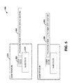
- FIG. 5 illustrates an alternative example of a laser pump system in accordance with an aspect of the present invention.
- FIG. 6 illustrates a schematic block diagram of a laser pump system that utilizes a light source driving a light stabilizer and employed as part of a fiber optic gyroscope in accordance with an aspect of the present invention.
- FIG. 7 illustrates a methodology for generating a pump laser output in accordance with an aspect of the present invention.
- the present invention is directed to providing wavelength and temperature stability for a laser source pump system.
- laser sources are often utilized in accordance with a gyroscope for positioning systems, for example.
- One example of such a laser source can be a 1480 nm InGaAsP laser.
- a typical requirement for such lasers is to be able to generate a consistent wavelength over a large temperature range (e.g., -60 to 90 deg C).
- Past attempts at achieving such stability have involved the use of polarization-maintaining (PM) optical fiber that was excited by a laser diode, however, such techniques were capable of launching unwanted propagation modes which reduced the efficiency of transmissions.
- PM polarization-maintaining
- the present invention mitigates unwanted propagation modes by utilizing a light stabilizer at the output of a coherent light source.
- the light stabilizer includes an optical fiber configured to pass one axis of propagation of the coherent output signal from the light source to a Bragg grating to generate a stabilized pump output signal for the system.
- the light stabilizer can include a single mode fiber etched with a fiber Bragg grating which utilizes a single axis of propagation to minimize transmission problems.
- the single mode fiber can be brought into contact with a temperature stabilizer (e.g., thermoelectric cooling (TEC) device) to facilitate temperature stability in the generated optical wavelength.
- the light stabilizer can include a polarizing fiber that can be employed in conjunction with the Bragg grating to generate a stabilized laser pump output signal.
- FIG. 1 illustrates a laser pump system 100 that employs a light stabilizer 110 to generate a stabilized pump output signal in accordance with an aspect of the present invention.
- the system 100 includes a light source 120 that generates a coherent output signal that is applied to the light stabilizer 110.
- the light stabilizer 110 includes an optical fiber 130 configured to pass one axis of propagation of the coherent output signal from the light source 110 to a Bragg grating 140 to generate a stabilized pump output signal for the system 100.
- the optical fiber 130 can be a single mode fiber that is configured with the Bragg grating 140 to pass the single axis of propagation of the coherent output signal from the light source 120.
- the optical fiber 130 can be a polarizing fiber configured to pass the single axis of propagation of the coherent output signal from the light source 120.
- a Polarizing Maintaining (PM) fiber and grating were coupled to a laser diode to form a laser source pump and light transmission system.
- the PM fiber did not offer suitable rejection of unwanted propagation frequencies or modes in the pump output signal, however.
- some frequencies may be applied to a desired axis of propagation and some are inadvertently transmitted in an unwanted axis of propagation.
- the axis can be referred to as fast and slow axis of propagation caused by birefringence of the PM material.
- the light stabilizer 110 employs a single mode fiber in one example or a polarizing fiber in another example to mitigate propagation of frequencies in multiple axis of the respective optical material.
- the single mode fiber and Bragg grating 140 provides a single axis of propagation thus mitigating the fast and slow axis transmission problems described herein.
- One aspect of single mode fiber however is to provide temperature stability to the fiber in order to properly utilize the single mode fiber.
- the single mode fiber can be mounted inside a respective laser cavity on a thermoelectric cooling device to provide such stability as will be illustrated and described below with respect to FIGS. 2 and 3 .
- the optical fiber 130 can be a polarizing fiber coupled to the Bragg grating 140.
- polarizing fiber and grating 140 solves the mixed propagation issues by providing a rejection of the undesired propagation mode (at the connection point to the laser diode) which is not provided by the PM fiber and grating. Such rejection increases the efficiency of the source pump and mitigates phase mixing problems during transmission.
- Such polarizing fiber and grating configuration are illustrated and described below with respect to FIG. 5 .
- FIG. 2 illustrates a schematic block diagram of a laser pump system 200 in accordance with an aspect of the present invention.
- the system 200 includes a light source 210 to generate a coherent output signal.
- a single mode fiber 220 e.g., fiber optic material having an etched Bragg grating receives the coherent output signal from the light source 210 and generates a stabilized pump output signal for the system 200.
- the system 200 also includes a temperature stabilizer 240 to provide temperature stability for the light source 210 and the single mode fiber 220.
- the temperature stabilizer 240 can be coupled to the light source 210 and the single mode fiber 220 as a substrate material, for example. As will be illustrated and described below with respect to FIG.
- the single mode fiber 220 can have a surface material that is metalized at least at one portion of the surface material (e.g., at two points along the fiber) to facilitate mechanical and wavelength stability within the fiber.
- the metalized portion of the surface material of the single mode fiber 220 can be soldered to the substrate material of the temperature stabilizer 240.
- the temperature stabilizer 240 can be a thermoelectric cooler although other cooling techniques are possible (e.g., liquid or chemical cooling).
- the etched Bragg grating can be positioned at a length that exceeds the decoherence length of the pump laser (e.g., about 3.8 mm to about 4 mm away from the light source 210 which will be illustrated below with respect to FIG. 2 .)
- the single mode fiber 220 can also include a lensed tip to couple to the light source 210.
- the light source 210 can be a 1480 nanometer wavelength laser diode source. Other wavelengths are possible, however, such as operating within a wavelength range from about 300 nanometers to about 4000 nanometers.
- the stabilized pump output signal can be employed to drive a fiber optic gyroscope, in one example application for the laser pump system 200.
- scale factor stability of the FOG is generally proportional to the source wavelength stability.
- the wavelength stability of a broadband fiber source can be limited by the power and wavelength stability of the pump laser.
- the system 200 provides a pump laser output with improved power and wavelength stability over a large temperature range and thus results in improved FOG scale factor stability.
- stabilized pump laser configurations utilized a spliced polarization maintaining (PM) fiber that was outside of the laser package.
- PM fiber spliced polarization maintaining
- the introduction of a temperature sensitive interferometer between the primary and external laser cavity can result in sinusoidal fluctuations in output power as well as the potential for a mode collapse, sometimes referred to as Mode Hopping.
- the laser pump system 200 prevents the introduction of an interferometer within the laser cavity, which suppresses temperature sensitive power and wavelength variations.
- the temperature stabilization of the grating can result in a more stable Bragg wavelength resulting in additional wavelength stability.
- the single mode fiber can be metalized in multiple locations and subsequently coupled to the substrate 240 at such locations to further promote mechanical and wavelength stability within the fiber.
- Such lights sources can include: 375 nm, 405 nm - InGaN blue-violet laser, 445 nm - InGaN blue laser, 473 nm - blue laser, 485 nm, 510 nm - (to ⁇ 525nm) green, 635 nm - AlGaInP, 640 nm - red, 657 nm - AlGaInP, 670 nm - AlGaInP, 760 nm - AlGaInP, 785 nm - GaAlAs, 808 nm - GaAlAs pumps in DPSS Nd:YAG lasers, 848 nm , 980 nm - InGaAs pump for optical amplifiers, for Yb:YAG DPSS lasers, 1064 nm - AlGaAs fiber-optic communication, DPSS
- the fiber Bragg grating (FBG) 230 is a type of distributed Bragg reflector constructed in a short segment of optical fiber that reflects particular wavelengths of light and transmits all others. This is achieved by creating a periodic variation in the refractive index of the fiber core, which generates a wavelength specific dielectric mirror.
- the fiber Bragg grating 230 can therefore be used as an inline optical filter to block certain wavelengths, or as a wavelength-specific reflector.
- the Bragg gratings 230 can be created by "inscribing" or “writing” systematic (periodic or aperiodic) variation of refractive index into the core of an optical fiber using an intense ultraviolet (UV) source such as a UV laser. Two example processes utilizing the UV laser source include interference and masking to produce the Bragg grating 230.
- UV intense ultraviolet
- FIG. 3 illustrates an example of a laser pump system 300 that employs single mode fiber with an etched grating and a thermoelectric cooled substrate in accordance with an aspect of the present invention.
- an InGaAsP light source 310 drives a single mode fiber 320, wherein the light source and single mode fiber are attached to a thermoelectric cooler (TEC) substrate 330.
- TEC thermoelectric cooler
- metallization points 340 and 350 can be added to the surface of the single mode fiber 320 and attached to the TEC substrate 340 via solder, for example.
- the single mode fiber 320 can be shorter than the substrate 330, cut to about the same length as the substrate, or it can protrude past the substrate.
- An etched grating is produced in the single mode fiber 320 and positioned at a length that exceeds the decoherence length of the pump laser and from where the single mode fiber and light source 310 are coupled.
- the coupling point between the light source 310 and the single mode fiber 320 can be achieved via a lensed tip on the single mode fiber, for example.
- the spacing of the etched grating on the single mode fiber 320 from the light source 310 is provided to address mode competition, wherein the introduction of an external reflection can result in mode competition between the primary laser cavity and the newly formed external cavity with the single mode fiber.
- mode competition wherein the introduction of an external reflection can result in mode competition between the primary laser cavity and the newly formed external cavity with the single mode fiber.
- the secondary cavity length is sufficiently long such that any reflections within the external cavity are substantially decoherent, wherein the decoherence length is dependent on the spectral structure exiting the primary laser cavity.
- the decoherence length of a 1 mm InGaAsP laser can be read from the coherence function, as illustrated in FIG. 4 . Reading from the graph in FIG.
- an optical path length difference (OPD) greater than 11 mm should suppress interference terms by at least 17dB.
- OPD optical path length difference
- the TEC substrate 330 can employ thermoelectric cooling that uses the Peltier effect to create a heat flux between the junction of two different types of materials.
- a Peltier cooler, heater, or thermoelectric heat pump is a solid-state active heat pump which transfers heat from one side of the device to the other, with consumption of electrical energy, depending on the direction of the current.
- Such an instrument is also referred to as a Peltier device, Peltier heat pump, solid state refrigerator, or thermoelectric cooler (TEC).
- the Peltier device is thus a heat pump: when direct current runs through it, heat is moved from one side to the other.
- other types of cooling are also possible.
- FIG. 5 illustrates an alternative example of a laser pump system 500 in accordance with an aspect of the present invention.
- the system 500 utilizes a laser module 510 having a laser diode 520 mounted on a substrate 530 (e.g., thermo cooled substrate).
- the laser diode 530 is then coupled to a polarizing fiber 540 having an etched Bragg grating.
- the use of polarizing fiber and grating 540 can result in a reduction in the optical power fluctuation proportional to the quality of extinction ratio of the polarizing fiber used.
- a polarizing fiber segment with a -3dB extinction ratio can result in a factor of two reduction in intensity sinusoids when compared to a high birefringence PM fiber of conventional systems.
- the polarizing fiber 540 can be comprised of a fiber which maintains the optical polarization state of the propagating light as well as rejecting light of the incorrect polarization state.
- a fiber Bragg grating can then be directly etched to the polarizing fiber as shown at 540. Since the external cavity (polarizing fiber segment) rejects unwanted polarization, the polarization extinction ratio (PER) of the laser to fiber coupling can be relaxed with no substantial degradation to performance. More specifically, a degradation in the laser to fiber coupling PER can result in power reduction, but the external cavity would no longer act as an interferometer due to birefringence variations over temperature or other environmental condition resulting in a stable optical power and wavelength.
- a separate FBG etched onto a polarizing maintaining (PM) fiber segment 550 can be spliced to the polarizing fiber element shown at 560.
- FIG. 6 illustrates a schematic block diagram of a laser pump system 600 that utilizes a pump with grating 612 (e.g., similar to system 100 of FIG. 1 above) driving a doped optical assembly 613 and employed as part of a fiber optic gyroscope in accordance with an aspect of the present invention.
- the system 600 can be configured as an interferometric fiber optic gyroscope (FOG) and includes an optical signal light source 612 that provides counter-propagating waves to a fiber optic sensing coil 620.
- Output from the pump 610 is fed to the doped optical assembly 613 which can include doped fiber, a wavelength division multiplexor, and an optical isolator, for example.
- a multifunction integrated optic chip (MIOC) 618 is connected to the fiber optic sensing coil 620.
- MIOC multifunction integrated optic chip
- a typical MIOC in a FOG system 600 includes components such as polarizers, phase modulators and a Y-coupler that are used in processing and controlling optical signals input to and from the fiber optic sensing coil 620.
- the output of the system 600 is the phase difference between two counter-propagating waves.
- the rotation rate of the coil about its sensing axis is obtained by dividing this phase difference by a scale factor of the FOG, referred to as the Sagnac scale factor.
- output from the optical assembly 613 can be fed to an optical splitter 615 which drives a depolarizer 624 and feeds a photo detector 626.
- the scale factor stability of fiber optic gyroscopes is affected by changes in the polarization state of the light in the fiber between the optical source and the MIOC 618. Changes in stress within the fiber can cause the polarization sate of light guided by the fiber to change. This stress may be mechanical or thermal in origin.
- the depolarizer 624 e.g., Lyot depolarizer
- the depolarizer 624 can be placed in the optical path between the optical source 612 and the MIOC 618 to adjust the polarization state for the optical light source signal as it propagates through the FOG.
- FIG. 7 an example method will be better appreciated with reference to FIG. 7 . While, for purposes of simplicity of explanation, the example method of FIG. 7 is shown and described as executing serially, it is to be understood and appreciated that the present examples are not limited by the illustrated order, as some actions could in other examples occur in different orders and/or concurrently from that shown and described herein. Moreover, it is not necessary that all described actions be performed to implement a method.
- FIG. 7 illustrates a methodology 700 for generating a pump laser output in accordance with an aspect of the present invention.
- the method 700 includes etching a Bragg grating into an optical fiber (e.g., single mode fiber or polarizing fiber). As noted previously, such etching can be applied by an ultraviolet source via masking and/or interference processes.
- the method 700 includes coupling the optical fiber to a coherent light source.
- the method 700 includes providing a stabilized pump output signal by configuring the Bragg grating and the optical fiber to pass one axis of propagation from the coherent light source.
- the method 700 can also include etching the Bragg grating into a single mode fiber to pass the one axis of propagation from the coherent light source.
- the method 700 can also include applying the stabilized pump output signal to a fiber optic gyroscope.
- the method 700 can include etching the Bragg grating into a polarizing fiber to pass the one axis of propagation from the coherent light source.
- the optical fiber can include a polarizing fiber that is coupled to a polarizing maintaining fiber having a Bragg grating to pass the one axis of propagation of the coherent light source.
Abstract
Description
- The present invention relates generally to optics, and more particularly to a system and method for generating a stabilized pump laser output.
- A laser source pump is a device to generate coherent light for use by various systems. Laser pumping is the act of energy transfer from an external source into the gain medium of a laser, wherein energy is absorbed in the medium, producing excited states in its atoms. When the number of particles in one excited state exceeds the number of particles in the ground state or a less-excited state, population inversion is achieved. In this condition, the mechanism of stimulated emission can take place and the medium can act as a laser or an optical amplifier. The pump energy is usually provided in the form of light or electric current.
- Such laser pump sources are often utilized in accordance with a gyroscope for positioning systems, for example. A major requirement for such lasers is to be able to generate a consistent wavelength over a vast temperature range (e.g., -60 to 90 deg C). Past attempts at achieving such stability have involved the use of polarization-maintaining (PM) optical fiber that was excited by a laser diode. The PM fiber was difficult to stabilize however as multiple propagation modes could be launched in the fiber that cause transmission inefficiencies.
- In an aspect of the invention, a laser pump system is provided. A system includes a light source that generates a coherent output signal. A light stabilizer comprising an optical fiber can be configured to pass one axis of propagation of the coherent output signal from the light source to a Bragg grating to generate a stabilized pump output signal for the system.
- In another aspect of the invention, a method includes etching a Bragg grating into an optical fiber. The method includes coupling the optical fiber to a coherent light source. The method also includes generating a stabilized pump output signal by configuring the Bragg grating and the optical fiber to pass one axis of propagation from the coherent light source.
- In yet another aspect of the invention, a system includes a light source that generates a coherent output signal. The system includes a light stabilizer comprising an optical fiber configured to pass one axis of propagation of the coherent output signal from the light source to a Bragg grating to generate a stabilized pump output signal for the system. The system also includes a substrate coupled to the light source to provide temperature stability for the light source.
-
FIG. 1 illustrates a schematic block diagram of a laser pump system that employs a light stabilizer to generate a stabilized pump output signal in accordance with an aspect of the present invention. -
FIG. 2 illustrates a schematic block diagram of a laser pump system in accordance with an aspect of the present invention. -
FIG. 3 illustrates an example of a laser pump system that employs single mode fiber with an etched grating and a thermoelectric cooled substrate in accordance with an aspect of the present invention. -
FIG. 4 illustrates an example coherence function in accordance with an aspect of the present invention. -
FIG. 5 illustrates an alternative example of a laser pump system in accordance with an aspect of the present invention. -
FIG. 6 illustrates a schematic block diagram of a laser pump system that utilizes a light source driving a light stabilizer and employed as part of a fiber optic gyroscope in accordance with an aspect of the present invention. -
FIG. 7 illustrates a methodology for generating a pump laser output in accordance with an aspect of the present invention. - Systems and methods for generating stabilized pump laser output are provided. In one example, the present invention is directed to providing wavelength and temperature stability for a laser source pump system. Such laser sources are often utilized in accordance with a gyroscope for positioning systems, for example. One example of such a laser source can be a 1480 nm InGaAsP laser. A typical requirement for such lasers is to be able to generate a consistent wavelength over a large temperature range (e.g., -60 to 90 deg C). Past attempts at achieving such stability have involved the use of polarization-maintaining (PM) optical fiber that was excited by a laser diode, however, such techniques were capable of launching unwanted propagation modes which reduced the efficiency of transmissions.
- The present invention mitigates unwanted propagation modes by utilizing a light stabilizer at the output of a coherent light source. The light stabilizer includes an optical fiber configured to pass one axis of propagation of the coherent output signal from the light source to a Bragg grating to generate a stabilized pump output signal for the system. In one example, the light stabilizer can include a single mode fiber etched with a fiber Bragg grating which utilizes a single axis of propagation to minimize transmission problems. Also, the single mode fiber can be brought into contact with a temperature stabilizer (e.g., thermoelectric cooling (TEC) device) to facilitate temperature stability in the generated optical wavelength. In another example, the light stabilizer can include a polarizing fiber that can be employed in conjunction with the Bragg grating to generate a stabilized laser pump output signal.
-
FIG. 1 illustrates alaser pump system 100 that employs alight stabilizer 110 to generate a stabilized pump output signal in accordance with an aspect of the present invention. Thesystem 100 includes alight source 120 that generates a coherent output signal that is applied to thelight stabilizer 110. Thelight stabilizer 110 includes anoptical fiber 130 configured to pass one axis of propagation of the coherent output signal from thelight source 110 to a Bragggrating 140 to generate a stabilized pump output signal for thesystem 100. In one example, theoptical fiber 130 can be a single mode fiber that is configured with the Bragggrating 140 to pass the single axis of propagation of the coherent output signal from thelight source 120. In another example, theoptical fiber 130 can be a polarizing fiber configured to pass the single axis of propagation of the coherent output signal from thelight source 120. - In previous systems, a Polarizing Maintaining (PM) fiber and grating were coupled to a laser diode to form a laser source pump and light transmission system. The PM fiber did not offer suitable rejection of unwanted propagation frequencies or modes in the pump output signal, however. In essence, when a PM fiber is used and attached to the laser diode source, some frequencies may be applied to a desired axis of propagation and some are inadvertently transmitted in an unwanted axis of propagation. The axis can be referred to as fast and slow axis of propagation caused by birefringence of the PM material. When frequencies are applied to both axis however, undesired phase shifts and source power degradations can be observed leading to instability in the pump output signal.
- The
light stabilizer 110 employs a single mode fiber in one example or a polarizing fiber in another example to mitigate propagation of frequencies in multiple axis of the respective optical material. The single mode fiber and Bragggrating 140 provides a single axis of propagation thus mitigating the fast and slow axis transmission problems described herein. One aspect of single mode fiber however is to provide temperature stability to the fiber in order to properly utilize the single mode fiber. Thus, the single mode fiber can be mounted inside a respective laser cavity on a thermoelectric cooling device to provide such stability as will be illustrated and described below with respect toFIGS. 2 and3 . - In another example, the
optical fiber 130 can be a polarizing fiber coupled to the Bragggrating 140. Such polarizing fiber and grating 140 solves the mixed propagation issues by providing a rejection of the undesired propagation mode (at the connection point to the laser diode) which is not provided by the PM fiber and grating. Such rejection increases the efficiency of the source pump and mitigates phase mixing problems during transmission. Such polarizing fiber and grating configuration are illustrated and described below with respect toFIG. 5 . -
FIG. 2 illustrates a schematic block diagram of alaser pump system 200 in accordance with an aspect of the present invention. Thesystem 200 includes alight source 210 to generate a coherent output signal. A single mode fiber 220 (e.g., fiber optic material) having an etched Bragg grating receives the coherent output signal from thelight source 210 and generates a stabilized pump output signal for thesystem 200. Thesystem 200 also includes atemperature stabilizer 240 to provide temperature stability for thelight source 210 and thesingle mode fiber 220. Thetemperature stabilizer 240 can be coupled to thelight source 210 and thesingle mode fiber 220 as a substrate material, for example. As will be illustrated and described below with respect toFIG. 3 , thesingle mode fiber 220 can have a surface material that is metalized at least at one portion of the surface material (e.g., at two points along the fiber) to facilitate mechanical and wavelength stability within the fiber. The metalized portion of the surface material of thesingle mode fiber 220 can be soldered to the substrate material of thetemperature stabilizer 240. In one specific example, thetemperature stabilizer 240 can be a thermoelectric cooler although other cooling techniques are possible (e.g., liquid or chemical cooling). - To facilitate wavelength stability, the etched Bragg grating can be positioned at a length that exceeds the decoherence length of the pump laser (e.g., about 3.8 mm to about 4 mm away from the
light source 210 which will be illustrated below with respect toFIG. 2 .) Thesingle mode fiber 220 can also include a lensed tip to couple to thelight source 210. As noted previously, in one example thelight source 210 can be a 1480 nanometer wavelength laser diode source. Other wavelengths are possible, however, such as operating within a wavelength range from about 300 nanometers to about 4000 nanometers. As will be described and illustrated below with respect toFIG. 4 , the stabilized pump output signal can be employed to drive a fiber optic gyroscope, in one example application for thelaser pump system 200. - When applying the
laser pump system 200 to a fiber optic gyroscopic (FOG) system, scale factor stability of the FOG is generally proportional to the source wavelength stability. The wavelength stability of a broadband fiber source can be limited by the power and wavelength stability of the pump laser. Thesystem 200 provides a pump laser output with improved power and wavelength stability over a large temperature range and thus results in improved FOG scale factor stability. In previous attempts to stabilize such systems, stabilized pump laser configurations utilized a spliced polarization maintaining (PM) fiber that was outside of the laser package. The birefringent nature of PM fiber can induce temperature dependent phase delays between the orthogonal propagation axes of the fiber, which results in optical interference. The introduction of a temperature sensitive interferometer between the primary and external laser cavity can result in sinusoidal fluctuations in output power as well as the potential for a mode collapse, sometimes referred to as Mode Hopping. Thelaser pump system 200 prevents the introduction of an interferometer within the laser cavity, which suppresses temperature sensitive power and wavelength variations. The temperature stabilization of the grating can result in a more stable Bragg wavelength resulting in additional wavelength stability. As will be illustrated below with respect toFIG. 2 , the single mode fiber can be metalized in multiple locations and subsequently coupled to thesubstrate 240 at such locations to further promote mechanical and wavelength stability within the fiber. - The following list provides but a few example types and wavelengths for
light sources 210. Such lights sources can include: 375 nm, 405 nm - InGaN blue-violet laser, 445 nm - InGaN blue laser, 473 nm - blue laser, 485 nm, 510 nm - (to ∼525nm) green, 635 nm - AlGaInP, 640 nm - red, 657 nm - AlGaInP, 670 nm - AlGaInP, 760 nm - AlGaInP, 785 nm - GaAlAs, 808 nm - GaAlAs pumps in DPSS Nd:YAG lasers, 848 nm , 980 nm - InGaAs pump for optical amplifiers, for Yb:YAG DPSS lasers, 1064 nm - AlGaAs fiber-optic communication, DPSS laser pump frequency, 1310 nm - InGaAsP, InGaAsN fiber-optic communication, 1480 nm - InGaAsP pump for optical amplifiers, 1512 nm - InGaAsP, 1550 nm - InGaAsP, InGaAsNSb fiber-optic communication, 1625 nm - InGaAsP fiber-optic communication, 1654 nm - InGaAsP, 1877 nm - GaSbAs, 2004 nm - GaSbAs, 2330 nm - GaSbAs,2680 nm - GaSbAs, 3030 nm - GaSbAs, and 3330 nm - GaSbAs, for example. - The fiber Bragg grating (FBG) 230 is a type of distributed Bragg reflector constructed in a short segment of optical fiber that reflects particular wavelengths of light and transmits all others. This is achieved by creating a periodic variation in the refractive index of the fiber core, which generates a wavelength specific dielectric mirror. The fiber Bragg grating 230 can therefore be used as an inline optical filter to block certain wavelengths, or as a wavelength-specific reflector. The Bragg gratings 230 can be created by "inscribing" or "writing" systematic (periodic or aperiodic) variation of refractive index into the core of an optical fiber using an intense ultraviolet (UV) source such as a UV laser. Two example processes utilizing the UV laser source include interference and masking to produce the Bragg grating 230.
-
FIG. 3 illustrates an example of alaser pump system 300 that employs single mode fiber with an etched grating and a thermoelectric cooled substrate in accordance with an aspect of the present invention. In theexample system 300, an InGaAsPlight source 310 drives asingle mode fiber 320, wherein the light source and single mode fiber are attached to a thermoelectric cooler (TEC)substrate 330. As shown, metallization points 340 and 350 can be added to the surface of thesingle mode fiber 320 and attached to theTEC substrate 340 via solder, for example. Thesingle mode fiber 320 can be shorter than thesubstrate 330, cut to about the same length as the substrate, or it can protrude past the substrate. An etched grating is produced in thesingle mode fiber 320 and positioned at a length that exceeds the decoherence length of the pump laser and from where the single mode fiber andlight source 310 are coupled. The coupling point between thelight source 310 and thesingle mode fiber 320 can be achieved via a lensed tip on the single mode fiber, for example. - The spacing of the etched grating on the
single mode fiber 320 from thelight source 310 is provided to address mode competition, wherein the introduction of an external reflection can result in mode competition between the primary laser cavity and the newly formed external cavity with the single mode fiber. In order to prevent such a competition, it is desired to ensure that the secondary cavity length is sufficiently long such that any reflections within the external cavity are substantially decoherent, wherein the decoherence length is dependent on the spectral structure exiting the primary laser cavity. For instance, the decoherence length of a 1 mm InGaAsP laser can be read from the coherence function, as illustrated inFIG. 4 . Reading from the graph inFIG. 4 , an optical path length difference (OPD) greater than 11 mm should suppress interference terms by at least 17dB. In order to obtain an 11 mm OPD in a fused silica core fiber, for example, it is desirable to ensure that the grating distance is greater than about 3.8 mm, for example. - The
TEC substrate 330 can employ thermoelectric cooling that uses the Peltier effect to create a heat flux between the junction of two different types of materials. A Peltier cooler, heater, or thermoelectric heat pump is a solid-state active heat pump which transfers heat from one side of the device to the other, with consumption of electrical energy, depending on the direction of the current. Such an instrument is also referred to as a Peltier device, Peltier heat pump, solid state refrigerator, or thermoelectric cooler (TEC). The Peltier device is thus a heat pump: when direct current runs through it, heat is moved from one side to the other. As noted previously, other types of cooling are also possible. -
FIG. 5 illustrates an alternative example of alaser pump system 500 in accordance with an aspect of the present invention. In one example, thesystem 500 utilizes alaser module 510 having alaser diode 520 mounted on a substrate 530 (e.g., thermo cooled substrate). Thelaser diode 530 is then coupled to apolarizing fiber 540 having an etched Bragg grating. The use of polarizing fiber and grating 540 can result in a reduction in the optical power fluctuation proportional to the quality of extinction ratio of the polarizing fiber used. For example, a polarizing fiber segment with a -3dB extinction ratio can result in a factor of two reduction in intensity sinusoids when compared to a high birefringence PM fiber of conventional systems. - The
polarizing fiber 540 can be comprised of a fiber which maintains the optical polarization state of the propagating light as well as rejecting light of the incorrect polarization state. A fiber Bragg grating can then be directly etched to the polarizing fiber as shown at 540. Since the external cavity (polarizing fiber segment) rejects unwanted polarization, the polarization extinction ratio (PER) of the laser to fiber coupling can be relaxed with no substantial degradation to performance. More specifically, a degradation in the laser to fiber coupling PER can result in power reduction, but the external cavity would no longer act as an interferometer due to birefringence variations over temperature or other environmental condition resulting in a stable optical power and wavelength. In another example, a separate FBG etched onto a polarizing maintaining (PM)fiber segment 550 can be spliced to the polarizing fiber element shown at 560. -
FIG. 6 illustrates a schematic block diagram of alaser pump system 600 that utilizes a pump with grating 612 (e.g., similar tosystem 100 ofFIG. 1 above) driving a dopedoptical assembly 613 and employed as part of a fiber optic gyroscope in accordance with an aspect of the present invention. Thesystem 600 can be configured as an interferometric fiber optic gyroscope (FOG) and includes an optical signallight source 612 that provides counter-propagating waves to a fiberoptic sensing coil 620. Output from the pump 610 is fed to the dopedoptical assembly 613 which can include doped fiber, a wavelength division multiplexor, and an optical isolator, for example. Within thesystem 600, a multifunction integrated optic chip (MIOC) 618 is connected to the fiberoptic sensing coil 620. - A typical MIOC in a
FOG system 600 includes components such as polarizers, phase modulators and a Y-coupler that are used in processing and controlling optical signals input to and from the fiberoptic sensing coil 620. The output of thesystem 600 is the phase difference between two counter-propagating waves. The rotation rate of the coil about its sensing axis is obtained by dividing this phase difference by a scale factor of the FOG, referred to as the Sagnac scale factor. As shown, output from theoptical assembly 613 can be fed to anoptical splitter 615 which drives a depolarizer 624 and feeds aphoto detector 626. - The scale factor stability of fiber optic gyroscopes (FOGs) is affected by changes in the polarization state of the light in the fiber between the optical source and the
MIOC 618. Changes in stress within the fiber can cause the polarization sate of light guided by the fiber to change. This stress may be mechanical or thermal in origin. The depolarizer 624 (e.g., Lyot depolarizer) can be placed in the optical path between theoptical source 612 and theMIOC 618 to adjust the polarization state for the optical light source signal as it propagates through the FOG. - In view of the foregoing structural and functional features described above, an example method will be better appreciated with reference to
FIG. 7 . While, for purposes of simplicity of explanation, the example method ofFIG. 7 is shown and described as executing serially, it is to be understood and appreciated that the present examples are not limited by the illustrated order, as some actions could in other examples occur in different orders and/or concurrently from that shown and described herein. Moreover, it is not necessary that all described actions be performed to implement a method. -
FIG. 7 illustrates amethodology 700 for generating a pump laser output in accordance with an aspect of the present invention. At 710, themethod 700 includes etching a Bragg grating into an optical fiber (e.g., single mode fiber or polarizing fiber). As noted previously, such etching can be applied by an ultraviolet source via masking and/or interference processes. At 720, themethod 700 includes coupling the optical fiber to a coherent light source. At 730, themethod 700 includes providing a stabilized pump output signal by configuring the Bragg grating and the optical fiber to pass one axis of propagation from the coherent light source. Themethod 700 can also include etching the Bragg grating into a single mode fiber to pass the one axis of propagation from the coherent light source. This can include applying the single mode fiber to a thermoelectric cooler to facilitate temperature stability in the single mode fiber. Themethod 700 can also include applying the stabilized pump output signal to a fiber optic gyroscope. In another aspect, themethod 700 can include etching the Bragg grating into a polarizing fiber to pass the one axis of propagation from the coherent light source.
In yet another example, the optical fiber can include a polarizing fiber that is coupled to a polarizing maintaining fiber having a Bragg grating to pass the one axis of propagation of the coherent light source. - What have been described above are examples of the present invention. It is, of course, not possible to describe every conceivable combination of components or methodologies for purposes of describing the present invention, but one of ordinary skill in the art will recognize that many further combinations and permutations of the present invention are possible. Accordingly, the present invention is intended to embrace all such alterations, modifications and variations that fall within the spirit and scope of the appended claims.
Claims (20)
- A system comprising:a light source that generates a coherent output signal; anda light stabilizer comprising an optical fiber configured to pass one axis of propagation of the coherent output signal from the light source to a Bragg grating to generate a stabilized pump output signal for the system.
- The system of claim 1, wherein the optical fiber is a single mode fiber that operates with the Bragg grating to pass the one axis of propagation of the coherent output signal.
- The system of claim 2, further comprising a temperature stabilizer to provide temperature stability for the light source and the single mode fiber.
- The system of claim 3, wherein the temperature stabilizer is coupled to the light source and the single mode fiber as a substrate material.
- The system of claim 4, wherein the single mode fiber has a surface material that is metalized at least at one portion of the surface material.
- The system of claim 2, wherein the temperature stabilizer is a thermoelectric cooler.
- The system of claim 1, wherein the etched Bragg grating is positioned at a distance away from the light source to facilitate decoherence of a returned signal.
- The system of claim 1, wherein the light source operates within a wavelength range from about 300 nanometers to about 4000 nanometers.
- The system of claim 1, wherein the optical fiber further comprises a polarizing fiber that operates with the Bragg grating to pass the one axis of propagation of the coherent output signal.
- The system of claim 1, wherein the optical fiber further comprises a polarizing fiber that is coupled to a polarizing maintaining fiber having a Bragg grating to pass the one axis of propagation of the coherent output signal.
- A fiber optic gyroscope comprising the system of claim 1, a coil, and a multifunction integrated optic chip (MIOC) that couples the system of claim 1 to the coil.
- A method comprising:etching a Bragg grating into an optical fiber;coupling the optical fiber to a coherent light source; andproviding a stabilized pump output signal by configuring the Bragg grating and the optical fiber to pass one axis of propagation from the coherent light source.
- The method of claim 12, further comprising etching the Bragg grating into a single mode fiber to pass the one axis of propagation from the coherent light source.
- The method of claim 13, further comprising applying the single mode fiber to a thermoelectric cooler to facilitate temperature stability in the single mode fiber.
- The method of claim 12, further comprising applying the stabilized pump output signal to a fiber optic gyroscope.
- The method of claim 12, further comprising etching the Bragg grating into a polarizing fiber to pass the one axis of propagation from the coherent light source.
- The method of claim 12, wherein the optical fiber further comprises a polarizing fiber that is coupled to a polarizing maintaining fiber having a Bragg grating to pass the one axis of propagation of the coherent light source.
- A system comprising:a light source that generates a coherent output signal;a light stabilizer comprising an optical fiber configured to pass one axis of propagation of the coherent output signal from the light source to a Bragg grating to generate a stabilized pump output signal for the system; anda substrate coupled to the light source to provide temperature stability for the light source.
- The system of claim 18, wherein optical fiber is a single mode fiber and the substrate is a thermoelectric cooler to provide temperature stability for the single mode fiber.
- The system of claim 18, wherein the optical fiber further comprises a polarizing fiber that operates with the Bragg grating to pass the one axis of propagation of the coherent output signal.
Applications Claiming Priority (1)
| Application Number | Priority Date | Filing Date | Title |
|---|---|---|---|
| US13/614,293 US9031366B2 (en) | 2012-09-13 | 2012-09-13 | Stabilized pump laser output system and method |
Publications (3)
| Publication Number | Publication Date |
|---|---|
| EP2709218A2 true EP2709218A2 (en) | 2014-03-19 |
| EP2709218A3 EP2709218A3 (en) | 2014-06-04 |
| EP2709218B1 EP2709218B1 (en) | 2018-12-19 |
Family
ID=49080700
Family Applications (1)
| Application Number | Title | Priority Date | Filing Date |
|---|---|---|---|
| EP13181882.5A Active EP2709218B1 (en) | 2012-09-13 | 2013-08-27 | Stabilized pump laser output system and method |
Country Status (3)
| Country | Link |
|---|---|
| US (1) | US9031366B2 (en) |
| EP (1) | EP2709218B1 (en) |
| JP (1) | JP6126502B2 (en) |
Families Citing this family (6)
| Publication number | Priority date | Publication date | Assignee | Title |
|---|---|---|---|---|
| US10161738B2 (en) * | 2012-12-31 | 2018-12-25 | Axsun Technologies, Inc. | OCT swept laser with cavity length compensation |
| US10323925B2 (en) * | 2015-10-23 | 2019-06-18 | University Of Washington | Compact portable double differential fiber optic Sagnac interferometer |
| US10186829B2 (en) | 2016-05-10 | 2019-01-22 | Ii-Vi Incorporated | Compact laser source with wavelength stabilized output |
| US10193306B2 (en) * | 2016-08-22 | 2019-01-29 | Morton Photonics Incorporated | Ultra-low noise, highly stable single-mode operation, high power, Bragg grating based semiconductor laser |
| CN111538072B (en) * | 2020-05-28 | 2021-05-28 | 吉林大学 | Total field magnetic measurement device suitable for underground and temperature drift suppression method |
| US11848539B2 (en) * | 2021-02-18 | 2023-12-19 | Ioptis Corp. | Narrow linewidth semiconductor laser device |
Family Cites Families (28)
| Publication number | Priority date | Publication date | Assignee | Title |
|---|---|---|---|---|
| JPS63223715A (en) * | 1987-03-13 | 1988-09-19 | Fujikura Ltd | Constant polarization optical circuit |
| JPH06129864A (en) * | 1992-10-21 | 1994-05-13 | Tokimec Inc | Polarizer for optical fiber gyro |
| US5659559A (en) * | 1994-06-28 | 1997-08-19 | Sdl, Inc. | Apparatus for generating a stabilized laser source |
| JP3380749B2 (en) * | 1995-03-21 | 2003-02-24 | エスディーエル インク. | Fiber grating stabilized diode laser |
| US5701318A (en) * | 1996-05-10 | 1997-12-23 | The Board Of Trustees Of The Leland Stanford Junior University | Polarized superfluorescent fiber sources |
| US5870417A (en) | 1996-12-20 | 1999-02-09 | Sdl, Inc. | Thermal compensators for waveguide DBR laser sources |
| US6072811A (en) * | 1998-02-11 | 2000-06-06 | Imra America | Integrated passively modelocked fiber lasers and method for constructing the same |
| JP2000147312A (en) | 1998-11-10 | 2000-05-26 | Furukawa Electric Co Ltd:The | Laser module and its production |
| JP2000183445A (en) * | 1998-12-16 | 2000-06-30 | Furukawa Electric Co Ltd:The | Semiconductor laser module |
| US6246816B1 (en) | 1999-07-30 | 2001-06-12 | Litton Systems, Inc. | Wavelength stabilized laser light source |
| US6760151B1 (en) | 2000-04-27 | 2004-07-06 | Jds Uniphase Corporation | Depolarized semiconductor laser sources |
| WO2002027876A1 (en) | 2000-09-28 | 2002-04-04 | Sumitomo Osaka Cement Co., Ltd. | Wavelength stabilized module, stable wavelength laser beam generating device and optical communication system |
| JP2002141608A (en) | 2000-11-02 | 2002-05-17 | Furukawa Electric Co Ltd:The | Semiconductor laser module and raman amplifier comprising it |
| JP2002261385A (en) * | 2001-03-02 | 2002-09-13 | Mitsubishi Electric Corp | Laser diode module |
| US6792008B2 (en) | 2001-04-30 | 2004-09-14 | Jds Uniphase Corporation | Tracking error suppression and method of reducing tracking error |
| US6704338B2 (en) | 2001-09-28 | 2004-03-09 | Furukawa Electric Co., Ltd. | Semiconductor laser device, semiconductor laser module, and semiconductor laser control method |
| US20030161379A1 (en) | 2001-12-26 | 2003-08-28 | Jds Uniphase Corporation | Laser package |
| US7649921B2 (en) | 2002-05-08 | 2010-01-19 | The Furukawa Electric Co., Ltd. | Laser module |
| US7257302B2 (en) * | 2003-06-03 | 2007-08-14 | Imra America, Inc. | In-line, high energy fiber chirped pulse amplification system |
| US20050053101A1 (en) * | 2003-09-09 | 2005-03-10 | Jian Liu | Mode selection for single frequency fiber laser |
| CA2502266A1 (en) | 2004-03-26 | 2005-09-26 | Kyocera Corporation | External resonator and semiconductor laser module using the same |
| EP1617244A1 (en) | 2004-06-29 | 2006-01-18 | STMicroelectronics S.r.l. | Optical device including a Bragg grating and method of manufacturing thereof |
| US20060251425A1 (en) * | 2004-12-23 | 2006-11-09 | K2 Optronics | Suppression of fiber-induced noise caused by narrow linewidth lasers |
| JP2006324334A (en) * | 2005-05-17 | 2006-11-30 | Noritsu Koki Co Ltd | Laser light emitting apparatus |
| US7899105B1 (en) * | 2005-06-15 | 2011-03-01 | Cvi Laser, Llc | Temperature control system for a frequency converted diode laser |
| JP5507874B2 (en) * | 2009-04-14 | 2014-05-28 | 株式会社島津製作所 | Wavelength conversion laser device |
| US9217681B2 (en) * | 2009-07-16 | 2015-12-22 | Hamidreza Alemohammad | Optical fiber sensor and methods of manufacture |
| US20140198317A1 (en) * | 2013-01-13 | 2014-07-17 | Honeywell International Inc. | Stablized pump laser with output reflector on polarizing optical fiber |
-
2012
- 2012-09-13 US US13/614,293 patent/US9031366B2/en active Active
-
2013
- 2013-08-27 EP EP13181882.5A patent/EP2709218B1/en active Active
- 2013-09-06 JP JP2013184864A patent/JP6126502B2/en active Active
Non-Patent Citations (1)
| Title |
|---|
| None |
Also Published As
| Publication number | Publication date |
|---|---|
| EP2709218A3 (en) | 2014-06-04 |
| US20140071455A1 (en) | 2014-03-13 |
| EP2709218B1 (en) | 2018-12-19 |
| JP2014057063A (en) | 2014-03-27 |
| JP6126502B2 (en) | 2017-05-10 |
| US9031366B2 (en) | 2015-05-12 |
Similar Documents
| Publication | Publication Date | Title |
|---|---|---|
| US9252559B2 (en) | Narrow bandwidth reflectors for reducing stimulated Brillouin scattering in optical cavities | |
| EP2709218B1 (en) | Stabilized pump laser output system and method | |
| KR101111432B1 (en) | Fiber lasers | |
| JP2001102685A (en) | Wavelength-stabilized laser light source | |
| US8885678B1 (en) | Ultra-low frequency noise external cavity semiconductor laser with integrated waveguide grating and modulation section electronically stabilized by dual frequency feedback control circuitry | |
| US6567438B2 (en) | Active and low-power laser stabilization | |
| JP2000036630A (en) | Optical signal surface | |
| EP2698605B1 (en) | Fiber resonator gyroscope with low round trip loss and high output power | |
| CN106019763A (en) | All-fiber continuous light and optical frequency comb locking device | |
| JP2002519868A (en) | High stability light source | |
| JPH0575194A (en) | Wavelength multimode synchronous laser equipment | |
| Saleh et al. | Optoelectronic oscillator based on fiber ring resonator: overall system optimization and phase noise reduction | |
| US6429965B1 (en) | Polarization and wavelength stable superfluorescent sources | |
| TWI493157B (en) | Coolerless fiber light source device for optical communications and optic sensors | |
| JP5324332B2 (en) | Optical frequency comb stabilized light source | |
| US20080231861A1 (en) | Polarization Maintaining Optical Delay Circuit | |
| Liu et al. | A fully hybrid integrated Erbium-based laser | |
| JP4194763B2 (en) | Superfluorescent source with stable polarization and wavelength | |
| JP6744942B2 (en) | Symmetric wavelength multiplexer for fiber optic gyro light source | |
| JP2010040731A (en) | Small-sized fiber-ring laser | |
| CN108039638A (en) | Low threshold twin-stage light spectrum reshaping flexible optical fibre high power mode-locked laser | |
| JP4809554B2 (en) | Semiconductor laser module and Raman amplifier using the same | |
| US20140198317A1 (en) | Stablized pump laser with output reflector on polarizing optical fiber | |
| Sulaiman et al. | Wavelength-spacing tunable S-band multi-wavelength fiber laser based on Lyot filter | |
| Skalský et al. | Improvement of the Temperature Stability of the Erbium-Doped Superfluorescent Fiber Source by Tuning the Reflectivity of the Fiber End |
Legal Events
| Date | Code | Title | Description |
|---|---|---|---|
| PUAI | Public reference made under article 153(3) epc to a published international application that has entered the european phase |
Free format text: ORIGINAL CODE: 0009012 |
|
| AK | Designated contracting states |
Kind code of ref document: A2 Designated state(s): AL AT BE BG CH CY CZ DE DK EE ES FI FR GB GR HR HU IE IS IT LI LT LU LV MC MK MT NL NO PL PT RO RS SE SI SK SM TR |
|
| AX | Request for extension of the european patent |
Extension state: BA ME |
|
| PUAL | Search report despatched |
Free format text: ORIGINAL CODE: 0009013 |
|
| AK | Designated contracting states |
Kind code of ref document: A3 Designated state(s): AL AT BE BG CH CY CZ DE DK EE ES FI FR GB GR HR HU IE IS IT LI LT LU LV MC MK MT NL NO PL PT RO RS SE SI SK SM TR |
|
| AX | Request for extension of the european patent |
Extension state: BA ME |
|
| RIC1 | Information provided on ipc code assigned before grant |
Ipc: H01S 5/14 20060101ALN20140430BHEP Ipc: H01S 5/024 20060101ALI20140430BHEP Ipc: H01S 5/065 20060101ALI20140430BHEP Ipc: H01S 5/022 20060101AFI20140430BHEP Ipc: G01C 19/72 20060101ALN20140430BHEP |
|
| RIN1 | Information on inventor provided before grant (corrected) |
Inventor name: DIMASHKIE, BASSAM S. |
|
| 17P | Request for examination filed |
Effective date: 20141204 |
|
| RBV | Designated contracting states (corrected) |
Designated state(s): AL AT BE BG CH CY CZ DE DK EE ES FI FR GB GR HR HU IE IS IT LI LT LU LV MC MK MT NL NO PL PT RO RS SE SI SK SM TR |
|
| 17Q | First examination report despatched |
Effective date: 20160412 |
|
| RIC1 | Information provided on ipc code assigned before grant |
Ipc: G01C 19/72 20060101ALN20180516BHEP Ipc: H01S 5/065 20060101ALI20180516BHEP Ipc: H01S 5/022 20060101AFI20180516BHEP Ipc: H01S 5/024 20060101ALI20180516BHEP Ipc: H01S 5/14 20060101ALN20180516BHEP |
|
| GRAP | Despatch of communication of intention to grant a patent |
Free format text: ORIGINAL CODE: EPIDOSNIGR1 |
|
| STAA | Information on the status of an ep patent application or granted ep patent |
Free format text: STATUS: GRANT OF PATENT IS INTENDED |
|
| INTG | Intention to grant announced |
Effective date: 20180705 |
|
| RAP1 | Party data changed (applicant data changed or rights of an application transferred) |
Owner name: NORTHROP GRUMMAN GUIDANCE AND ELECTRONIC COMPANY, |
|
| GRAS | Grant fee paid |
Free format text: ORIGINAL CODE: EPIDOSNIGR3 |
|
| GRAA | (expected) grant |
Free format text: ORIGINAL CODE: 0009210 |
|
| STAA | Information on the status of an ep patent application or granted ep patent |
Free format text: STATUS: THE PATENT HAS BEEN GRANTED |
|
| AK | Designated contracting states |
Kind code of ref document: B1 Designated state(s): AL AT BE BG CH CY CZ DE DK EE ES FI FR GB GR HR HU IE IS IT LI LT LU LV MC MK MT NL NO PL PT RO RS SE SI SK SM TR |
|
| REG | Reference to a national code |
Ref country code: GB Ref legal event code: FG4D |
|
| REG | Reference to a national code |
Ref country code: CH Ref legal event code: EP |
|
| REG | Reference to a national code |
Ref country code: IE Ref legal event code: FG4D |
|
| REG | Reference to a national code |
Ref country code: DE Ref legal event code: R096 Ref document number: 602013048361 Country of ref document: DE |
|
| REG | Reference to a national code |
Ref country code: AT Ref legal event code: REF Ref document number: 1079703 Country of ref document: AT Kind code of ref document: T Effective date: 20190115 |
|
| REG | Reference to a national code |
Ref country code: NL Ref legal event code: MP Effective date: 20181219 |
|
| PG25 | Lapsed in a contracting state [announced via postgrant information from national office to epo] |
Ref country code: LV Free format text: LAPSE BECAUSE OF FAILURE TO SUBMIT A TRANSLATION OF THE DESCRIPTION OR TO PAY THE FEE WITHIN THE PRESCRIBED TIME-LIMIT Effective date: 20181219 Ref country code: HR Free format text: LAPSE BECAUSE OF FAILURE TO SUBMIT A TRANSLATION OF THE DESCRIPTION OR TO PAY THE FEE WITHIN THE PRESCRIBED TIME-LIMIT Effective date: 20181219 Ref country code: BG Free format text: LAPSE BECAUSE OF FAILURE TO SUBMIT A TRANSLATION OF THE DESCRIPTION OR TO PAY THE FEE WITHIN THE PRESCRIBED TIME-LIMIT Effective date: 20190319 Ref country code: NO Free format text: LAPSE BECAUSE OF FAILURE TO SUBMIT A TRANSLATION OF THE DESCRIPTION OR TO PAY THE FEE WITHIN THE PRESCRIBED TIME-LIMIT Effective date: 20190319 Ref country code: FI Free format text: LAPSE BECAUSE OF FAILURE TO SUBMIT A TRANSLATION OF THE DESCRIPTION OR TO PAY THE FEE WITHIN THE PRESCRIBED TIME-LIMIT Effective date: 20181219 Ref country code: LT Free format text: LAPSE BECAUSE OF FAILURE TO SUBMIT A TRANSLATION OF THE DESCRIPTION OR TO PAY THE FEE WITHIN THE PRESCRIBED TIME-LIMIT Effective date: 20181219 |
|
| REG | Reference to a national code |
Ref country code: LT Ref legal event code: MG4D |
|
| REG | Reference to a national code |
Ref country code: AT Ref legal event code: MK05 Ref document number: 1079703 Country of ref document: AT Kind code of ref document: T Effective date: 20181219 |
|
| PG25 | Lapsed in a contracting state [announced via postgrant information from national office to epo] |
Ref country code: SE Free format text: LAPSE BECAUSE OF FAILURE TO SUBMIT A TRANSLATION OF THE DESCRIPTION OR TO PAY THE FEE WITHIN THE PRESCRIBED TIME-LIMIT Effective date: 20181219 Ref country code: RS Free format text: LAPSE BECAUSE OF FAILURE TO SUBMIT A TRANSLATION OF THE DESCRIPTION OR TO PAY THE FEE WITHIN THE PRESCRIBED TIME-LIMIT Effective date: 20181219 Ref country code: AL Free format text: LAPSE BECAUSE OF FAILURE TO SUBMIT A TRANSLATION OF THE DESCRIPTION OR TO PAY THE FEE WITHIN THE PRESCRIBED TIME-LIMIT Effective date: 20181219 Ref country code: GR Free format text: LAPSE BECAUSE OF FAILURE TO SUBMIT A TRANSLATION OF THE DESCRIPTION OR TO PAY THE FEE WITHIN THE PRESCRIBED TIME-LIMIT Effective date: 20190320 |
|
| PG25 | Lapsed in a contracting state [announced via postgrant information from national office to epo] |
Ref country code: NL Free format text: LAPSE BECAUSE OF FAILURE TO SUBMIT A TRANSLATION OF THE DESCRIPTION OR TO PAY THE FEE WITHIN THE PRESCRIBED TIME-LIMIT Effective date: 20181219 |
|
| PG25 | Lapsed in a contracting state [announced via postgrant information from national office to epo] |
Ref country code: ES Free format text: LAPSE BECAUSE OF FAILURE TO SUBMIT A TRANSLATION OF THE DESCRIPTION OR TO PAY THE FEE WITHIN THE PRESCRIBED TIME-LIMIT Effective date: 20181219 Ref country code: PT Free format text: LAPSE BECAUSE OF FAILURE TO SUBMIT A TRANSLATION OF THE DESCRIPTION OR TO PAY THE FEE WITHIN THE PRESCRIBED TIME-LIMIT Effective date: 20190419 Ref country code: CZ Free format text: LAPSE BECAUSE OF FAILURE TO SUBMIT A TRANSLATION OF THE DESCRIPTION OR TO PAY THE FEE WITHIN THE PRESCRIBED TIME-LIMIT Effective date: 20181219 Ref country code: PL Free format text: LAPSE BECAUSE OF FAILURE TO SUBMIT A TRANSLATION OF THE DESCRIPTION OR TO PAY THE FEE WITHIN THE PRESCRIBED TIME-LIMIT Effective date: 20181219 |
|
| PG25 | Lapsed in a contracting state [announced via postgrant information from national office to epo] |
Ref country code: IS Free format text: LAPSE BECAUSE OF FAILURE TO SUBMIT A TRANSLATION OF THE DESCRIPTION OR TO PAY THE FEE WITHIN THE PRESCRIBED TIME-LIMIT Effective date: 20190419 Ref country code: SK Free format text: LAPSE BECAUSE OF FAILURE TO SUBMIT A TRANSLATION OF THE DESCRIPTION OR TO PAY THE FEE WITHIN THE PRESCRIBED TIME-LIMIT Effective date: 20181219 Ref country code: RO Free format text: LAPSE BECAUSE OF FAILURE TO SUBMIT A TRANSLATION OF THE DESCRIPTION OR TO PAY THE FEE WITHIN THE PRESCRIBED TIME-LIMIT Effective date: 20181219 Ref country code: SM Free format text: LAPSE BECAUSE OF FAILURE TO SUBMIT A TRANSLATION OF THE DESCRIPTION OR TO PAY THE FEE WITHIN THE PRESCRIBED TIME-LIMIT Effective date: 20181219 Ref country code: EE Free format text: LAPSE BECAUSE OF FAILURE TO SUBMIT A TRANSLATION OF THE DESCRIPTION OR TO PAY THE FEE WITHIN THE PRESCRIBED TIME-LIMIT Effective date: 20181219 |
|
| REG | Reference to a national code |
Ref country code: DE Ref legal event code: R097 Ref document number: 602013048361 Country of ref document: DE |
|
| PLBE | No opposition filed within time limit |
Free format text: ORIGINAL CODE: 0009261 |
|
| STAA | Information on the status of an ep patent application or granted ep patent |
Free format text: STATUS: NO OPPOSITION FILED WITHIN TIME LIMIT |
|
| PG25 | Lapsed in a contracting state [announced via postgrant information from national office to epo] |
Ref country code: DK Free format text: LAPSE BECAUSE OF FAILURE TO SUBMIT A TRANSLATION OF THE DESCRIPTION OR TO PAY THE FEE WITHIN THE PRESCRIBED TIME-LIMIT Effective date: 20181219 Ref country code: AT Free format text: LAPSE BECAUSE OF FAILURE TO SUBMIT A TRANSLATION OF THE DESCRIPTION OR TO PAY THE FEE WITHIN THE PRESCRIBED TIME-LIMIT Effective date: 20181219 |
|
| 26N | No opposition filed |
Effective date: 20190920 |
|
| PG25 | Lapsed in a contracting state [announced via postgrant information from national office to epo] |
Ref country code: SI Free format text: LAPSE BECAUSE OF FAILURE TO SUBMIT A TRANSLATION OF THE DESCRIPTION OR TO PAY THE FEE WITHIN THE PRESCRIBED TIME-LIMIT Effective date: 20181219 |
|
| PG25 | Lapsed in a contracting state [announced via postgrant information from national office to epo] |
Ref country code: TR Free format text: LAPSE BECAUSE OF FAILURE TO SUBMIT A TRANSLATION OF THE DESCRIPTION OR TO PAY THE FEE WITHIN THE PRESCRIBED TIME-LIMIT Effective date: 20181219 |
|
| PG25 | Lapsed in a contracting state [announced via postgrant information from national office to epo] |
Ref country code: LU Free format text: LAPSE BECAUSE OF NON-PAYMENT OF DUE FEES Effective date: 20190827 Ref country code: MC Free format text: LAPSE BECAUSE OF FAILURE TO SUBMIT A TRANSLATION OF THE DESCRIPTION OR TO PAY THE FEE WITHIN THE PRESCRIBED TIME-LIMIT Effective date: 20181219 Ref country code: LI Free format text: LAPSE BECAUSE OF NON-PAYMENT OF DUE FEES Effective date: 20190831 Ref country code: CH Free format text: LAPSE BECAUSE OF NON-PAYMENT OF DUE FEES Effective date: 20190831 |
|
| REG | Reference to a national code |
Ref country code: BE Ref legal event code: MM Effective date: 20190831 |
|
| PG25 | Lapsed in a contracting state [announced via postgrant information from national office to epo] |
Ref country code: IE Free format text: LAPSE BECAUSE OF NON-PAYMENT OF DUE FEES Effective date: 20190827 |
|
| PG25 | Lapsed in a contracting state [announced via postgrant information from national office to epo] |
Ref country code: BE Free format text: LAPSE BECAUSE OF NON-PAYMENT OF DUE FEES Effective date: 20190831 |
|
| PG25 | Lapsed in a contracting state [announced via postgrant information from national office to epo] |
Ref country code: CY Free format text: LAPSE BECAUSE OF FAILURE TO SUBMIT A TRANSLATION OF THE DESCRIPTION OR TO PAY THE FEE WITHIN THE PRESCRIBED TIME-LIMIT Effective date: 20181219 |
|
| PG25 | Lapsed in a contracting state [announced via postgrant information from national office to epo] |
Ref country code: HU Free format text: LAPSE BECAUSE OF FAILURE TO SUBMIT A TRANSLATION OF THE DESCRIPTION OR TO PAY THE FEE WITHIN THE PRESCRIBED TIME-LIMIT; INVALID AB INITIO Effective date: 20130827 Ref country code: MT Free format text: LAPSE BECAUSE OF FAILURE TO SUBMIT A TRANSLATION OF THE DESCRIPTION OR TO PAY THE FEE WITHIN THE PRESCRIBED TIME-LIMIT Effective date: 20181219 |
|
| PG25 | Lapsed in a contracting state [announced via postgrant information from national office to epo] |
Ref country code: MK Free format text: LAPSE BECAUSE OF FAILURE TO SUBMIT A TRANSLATION OF THE DESCRIPTION OR TO PAY THE FEE WITHIN THE PRESCRIBED TIME-LIMIT Effective date: 20181219 |
|
| P01 | Opt-out of the competence of the unified patent court (upc) registered |
Effective date: 20230607 |
|
| PGFP | Annual fee paid to national office [announced via postgrant information from national office to epo] |
Ref country code: IT Payment date: 20230825 Year of fee payment: 11 Ref country code: GB Payment date: 20230822 Year of fee payment: 11 |
|
| PGFP | Annual fee paid to national office [announced via postgrant information from national office to epo] |
Ref country code: FR Payment date: 20230824 Year of fee payment: 11 Ref country code: DE Payment date: 20230821 Year of fee payment: 11 |