EP2708394A2 - Commercial vehicle with a slidable side curtain - Google Patents
Commercial vehicle with a slidable side curtain Download PDFInfo
- Publication number
- EP2708394A2 EP2708394A2 EP13003533.0A EP13003533A EP2708394A2 EP 2708394 A2 EP2708394 A2 EP 2708394A2 EP 13003533 A EP13003533 A EP 13003533A EP 2708394 A2 EP2708394 A2 EP 2708394A2
- Authority
- EP
- European Patent Office
- Prior art keywords
- tarpaulin
- clamping
- shaft
- tensioning
- transport vehicle
- Prior art date
- Legal status (The legal status is an assumption and is not a legal conclusion. Google has not performed a legal analysis and makes no representation as to the accuracy of the status listed.)
- Granted
Links
- 238000007789 sealing Methods 0.000 claims 1
- 238000010276 construction Methods 0.000 description 2
- 230000035515 penetration Effects 0.000 description 2
- 230000001419 dependent effect Effects 0.000 description 1
- 238000006073 displacement reaction Methods 0.000 description 1
- 230000002040 relaxant effect Effects 0.000 description 1
- 238000004804 winding Methods 0.000 description 1
Images


Classifications
-
- B—PERFORMING OPERATIONS; TRANSPORTING
- B60—VEHICLES IN GENERAL
- B60J—WINDOWS, WINDSCREENS, NON-FIXED ROOFS, DOORS, OR SIMILAR DEVICES FOR VEHICLES; REMOVABLE EXTERNAL PROTECTIVE COVERINGS SPECIALLY ADAPTED FOR VEHICLES
- B60J5/00—Doors
- B60J5/04—Doors arranged at the vehicle sides
- B60J5/06—Doors arranged at the vehicle sides slidable; foldable
- B60J5/062—Doors arranged at the vehicle sides slidable; foldable for utility vehicles or public transport
- B60J5/065—Doors arranged at the vehicle sides slidable; foldable for utility vehicles or public transport with non-rigid elements, e.g. side curtains
Definitions
- the invention relates to a transport vehicle with a closed at least partially via sliding tarpaulin vehicle body, wherein a sliding tarpaulin seen in Transportlanguage front and / or rear end to a tarpaulin tension profile with a tension profile and / or a tensioning shaft can be fixed and with Zollkrampen having zipper securing down the sliding tarpaulin by means of a particular designed as a closure part customs closure.
- Transport vehicles with a vehicle body with lateral sliding tarpaulins are well known.
- vehicle bodies In order to make such vehicle bodies inaccessible to third parties, they have to have a customs closure device in order to make the sliding tarpaulin more secure against being seized on loose sides.
- Custom seals serve to secure sealed vehicle superstructures in such a way that unauthorized access to the cargo is always visible. Therefore, a sufficiently secure penetration protection on sliding tarpaulin vehicles must be provided. The penetration protection must be secured over the full length of the transport vehicle. Sliding tarpaulins are usually tensioned in their final position.
- a generally plate-shaped hinged TIR customs security is provided, which covers the clamping mechanism and which in addition is penetrated by a Zollkrampe in turn, through which the ZollverBankseil is guided.
- the associated construction costs are significant.
- a tarpaulin to be provided in the area of the tarpaulin profile is designed as a tarpaulin part which can be inserted into the tension profile receiver, which protrudes from the tension profile receiver and is not fixed in position within the tension profile receiver from the outside and / or that a Zollkrampe to be provided in the region of a clamping shaft is designed as a Zollkrampenteil to be arranged rotatably on the clamping shaft, so that the winding / tensioning of the tarpaulin is possible.
- the tarpaulin ramp on the tensioning shaft prevents lifting the tensioning shaft and thus the opening of the tarpaulin.
- the tensioning mechanism is also secured by the customs rope against unauthorized relaxation of the tarpaulin.
- the clamping mechanism is located below the clamping profile and allows tensioning or relaxing the side tarpaulin over the square.
- a transport vehicle in which by the simple provision of a Zollkrampenteils within the tarpaulin tension profile or on the tensioning shaft at the ends of the sliding tarpaulin each a secure customs seal can be realized.
- a Zollkrampenteil can be rotatably arranged on this clamping shaft.
- the Zollkrampenteil passes through the corresponding receptacle of the tarpaulin tension profile and protrudes outwards, so that a Zollver gleichseil can be passed through the Zollkrampenteil.
- the Zollkrampenteil can be secured from the inside, ie from a point that is no longer accessible from the outside after final securing the customs closure device, against unintentional sliding upwards.
- a further rotation is not possible because the customs securing cable is also guided by the clamping mechanism. This can be represented in the areas of the ends of sliding tarpaulins by this simple training in terms of construction safe secure zipper.
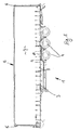
- a transport vehicle 1 with a vehicle body 2 is shown in the drawing, which is supported by a vehicle chassis 3 and wheels 4 on the ground.
- a vehicle chassis 3 and wheels 4 At the end corner stanchions 5 and 6 are provided, between which a generally estimated with 7 side sliding tarpaulin, which is to be tightened by means of tension straps 8 in its closed position with the vehicle chassis 7.
- a customs cable 9 is indicated, the corresponding Zollkrampeningn 10 interspersed in the side areas to represent a ZollverBankvorraum.
- a tarp tension profile 11 is formed on the front end edge or on the front corner stanchion 5, and a tensioning shaft 19 in the region of the rear corner stanchion 6, which is explained in more detail in the further figures.
- Fig. 2 is schematically and perspectively the above-mentioned tarp tension profile 11 provided with a trained as Einhakance clamping profile holder 12.
- a Zollkrampenteil 13 is inserted into this Spannprofilance 12, which is sleeve-shaped or tubular formed with a staple approach 13.1, which protrudes from the Spannprofiling 12 and then can be penetrated by a Zollver gleichseil. With a fuse that engages from the inside, the Zollkrampenteil 12 can be secured, for example by means of clamping.
- a tensioning shaft 14 is shown, which should be arranged in the region of the rear corner stanchion 6. This has a receptacle 15 for a kederförmiges end of the sliding tarpaulin 7.
- a sleeve-shaped Zollkrampenteil 13 is provided with the Zollkrampentext 13.1, which is arranged in the non-fixed state on the lateral surface of the tensioning shaft 14, that it can be rotated relative to the Zollkrampenteil 13 for the purpose of tension of the tarpaulin 7.
- the inchpiston part 13 can again be prevented from being accessible from the outside, ie secured from the inside, with a securing element against an up and down movement or any other rotation.
- the Zollkrampenteil is not secured against twisting.
- the axial displacement of the Zollkrampenteils is ensured by acting as a stop adapter 16.
- the tension shaft can not move up and not solve the tarp so.
- the tensioning mechanism is secured by the inserted ropes and thus prevents unwinding or opening of the tarpaulin.
Abstract
Description
Die Erfindung bezieht sich auf ein Transportfahrzeug mit einem zumindest bereichsweise über Schiebeplanen verschließbaren Fahrzeugaufbau, wobei eine Schiebeplane an ihrem in Transportfahrzeugrichtung gesehen vorderen und/oder hinteren Ende an einem Planenspannprofil mit einer Spannprofilaufnahme und/oder einer Spannwelle festlegbar ist und mit Zollkrampen aufweisenden Zollverschlusssicherung zur Festlegung der Schiebeplane mittels eines insbesondere als Verschlussteil ausgebildeten Zollverschlusses.The invention relates to a transport vehicle with a closed at least partially via sliding tarpaulin vehicle body, wherein a sliding tarpaulin seen in Transportfahrzeugrichtung front and / or rear end to a tarpaulin tension profile with a tension profile and / or a tensioning shaft can be fixed and with Zollkrampen having zipper securing down the sliding tarpaulin by means of a particular designed as a closure part customs closure.
Transportfahrzeuge mit einem Fahrzeugaufbau mit seitlichen Schiebeplanen sind allgemein bekannt. Um solche Fahrzeugaufbauten für Dritte unzugänglich auszubilden, haben diese eine Zollverschlussvorrichtung aufzuweisen, um die Schiebeplane gegenüber einem Durchgreifen an losen Seiten zollsicher zu gestalten. Zollverschlüsse dienen dazu, verplombte Fahrzeugaufbauten so zu sichern, dass ein unerlaubter Zugriff auf das Ladegut in jedem Falle sichbar ist. Deshalb muss ein ausreichend sicherer Durchgreifschutz an Schiebeplanenfahrzeugen vorgesehen sein. Der Durchgreifschutz ist über die volle Länge des Transportfahrzeuges abzusichern. Schiebeplanen sind in ihrer Endstellung üblicherweise zu spannen.Transport vehicles with a vehicle body with lateral sliding tarpaulins are well known. In order to make such vehicle bodies inaccessible to third parties, they have to have a customs closure device in order to make the sliding tarpaulin more secure against being seized on loose sides. Custom seals serve to secure sealed vehicle superstructures in such a way that unauthorized access to the cargo is always visible. Therefore, a sufficiently secure penetration protection on sliding tarpaulin vehicles must be provided. The penetration protection must be secured over the full length of the transport vehicle. Sliding tarpaulins are usually tensioned in their final position.
Dazu ist bekannt, entweder am vorderen und am hinteren Ende des Fahrzeugaufbaus jeweils Spannwellen vorzusehen oder alternativ an einer vorderen oder einer hinteren Seite des Fahrzeugaufbaus, jeweils in Fahrzeuglängsrichtung betrachtet, ein Spannprofil zum Festlegen der Seitenplane vorzusehen. Die Spannwelle ist über einen Spannmechanismus zu betätigen, um die Schiebeplane in ihrer geschlossenen Endstellung entsprechend zu spannen. Um die Zollsicherheit herbeizuführen, hat die Zollverschlussvorrichtung nicht nur ein Zollverschlussseil aufzuweisen, das entsprechende Zollkrampen an den Seitenflächen des Fahrzeugaufbaus durchsetzt. Vielmehr ist darüber hinaus auch sicherzustellen, dass der Spannmechanismus für die Spannwelle von außen her nicht gelöst werden kann. Daher ist insbesondere eine in aller Regel plattenförmige klappbare TIR-Zollsicherheit vorzusehen, die den Spannmechanismus abdeckt und der darüber hinaus von einer Zollkrampe seinerseits durchsetzt ist, durch die das Zollverschlussseil geführt ist. Der damit einhergehende Bauaufwand ist erheblich.For this purpose, it is known to provide either at the front and at the rear end of the vehicle body respectively clamping shafts or alternatively viewed at a front or a rear side of the vehicle body, respectively in the vehicle longitudinal direction, to provide a tension profile for fixing the side tarpaulin. The tensioning shaft must be actuated by a tensioning mechanism in order to tension the sliding tarpaulin accordingly in its closed end position. In order to provide customs security, the customs fastener device not only has to have a duty-lock rope which penetrates appropriate inching ropes on the side surfaces of the vehicle body. Rather, it must also be ensured that the clamping mechanism for the clamping shaft can not be released from the outside. Therefore, in particular, a generally plate-shaped hinged TIR customs security is provided, which covers the clamping mechanism and which in addition is penetrated by a Zollkrampe in turn, through which the Zollverschlussseil is guided. The associated construction costs are significant.
Es ist Aufgabe der vorliegenden Erfindung, ein Transportfahrzeug der eingangs genannten Art dahingehend zu verbessern, dass ein sicherer Zollverschluss realisiert werden kann, der jedoch weniger bauaufwendig gestaltet ist.It is an object of the present invention to improve a transport vehicle of the type mentioned in that a secure customs seal can be realized, which is designed less bulky.
Zur Lösung dieser Aufgabe ist bei einem Transportfahrzeug der eingangs genannten Art vorgesehen, dass eine im Bereich des Planenspannprofils vorzusehende Zollkrampe als in die Spannprofilaufnahme einsetzbares Zollkrampenteil ausgebildet ist, das aus der Spannprofilaufnahme herausragt und innerhalb der Spannsprofilaufnahme von außen her nicht zugänglich lagefixiert ist und/oder dass eine im Bereich einer Spannwelle vorzusehende Zollkrampe als ein drehbar auf der Spannwelle anzuordnendes Zollkrampenteil ausgebildet ist, so dass das Aufwickeln/Spannen der Plane möglich ist. Die Planenkrampe an der Spannwelle verhindert das Herausheben der Spannwelle und somit das Öffnen der Plane. Der Spannmechanismus wird auch durch das Zollseil gegen unbefugtes Entspannen der Plane gesichert. Der Spannmechanismus befindet sich unterhalb des Spannprofils und ermöglicht das Spannen bzw. Entspannen der Seitenplane über den Vierkant.To solve this problem, it is provided in a transport vehicle of the type mentioned above that a tarpaulin to be provided in the area of the tarpaulin profile is designed as a tarpaulin part which can be inserted into the tension profile receiver, which protrudes from the tension profile receiver and is not fixed in position within the tension profile receiver from the outside and / or that a Zollkrampe to be provided in the region of a clamping shaft is designed as a Zollkrampenteil to be arranged rotatably on the clamping shaft, so that the winding / tensioning of the tarpaulin is possible. The tarpaulin ramp on the tensioning shaft prevents lifting the tensioning shaft and thus the opening of the tarpaulin. The tensioning mechanism is also secured by the customs rope against unauthorized relaxation of the tarpaulin. The clamping mechanism is located below the clamping profile and allows tensioning or relaxing the side tarpaulin over the square.
Damit ist ein Transportfahrzeug geschaffen, bei dem durch das einfache Vorsehen eines Zollkrampenteils innerhalb des Planenspannprofils oder an der Spannwelle an den Enden der Schiebeplane jeweils ein sicherer Zollverschluss realisiert sein kann. Ist beispielsweise nicht nur ein als Einhakleiste ausbildendes Planenspannprofil mit dem Zollkrampenverschluss vorgesehen, sondern auch eine Spannwelle, die über einen Spannmechanismus zu verdrehen ist, kann auf dieser Spannwelle das Zollkrampenbauteil drehbar angeordnet werden. Das Zollkrampenteil durchsetzt die entsprechende Aufnahme des Planenspannprofils und ragt nach außen vor, so dass ein Zollverschlussseil durch die Zollkrampenteil geführt sein kann. Nachdem die Spannwelle die entsprechende Spannendstellung erreicht hat, kann das Zollkrampenteil von innen her, d.h. von einer Stelle, die nach Endsicherung der Zollverschlussvorrichtung von außen nicht mehr zugänglich ist, gegen ein unbeabsichtigtes Verschieben nach oben nach unten gesichert werden. Eine weitere Verdrehung ist nicht möglich, da das Zollsicherungsseil auch durch den Spannmechanismus geführt wird. Dadurch kann durch diese einfache Ausbildung in baulicher Hinsicht eine sichere Zollverschlusssicherung in den Bereichen der Enden von Schiebeplanen dargestellt werden.Thus, a transport vehicle is provided, in which by the simple provision of a Zollkrampenteils within the tarpaulin tension profile or on the tensioning shaft at the ends of the sliding tarpaulin each a secure customs seal can be realized. For example, if not only designed as Einhakleiste tarpaulin profile with the Zollkrampenverschluss, but also a clamping shaft, which is to be rotated by a clamping mechanism, the Zollkrampenbauteil can be rotatably arranged on this clamping shaft. The Zollkrampenteil passes through the corresponding receptacle of the tarpaulin tension profile and protrudes outwards, so that a Zollverschlussseil can be passed through the Zollkrampenteil. After the tensioning shaft has reached the corresponding clamping end position, the Zollkrampenteil can be secured from the inside, ie from a point that is no longer accessible from the outside after final securing the customs closure device, against unintentional sliding upwards. A further rotation is not possible because the customs securing cable is also guided by the clamping mechanism. This can be represented in the areas of the ends of sliding tarpaulins by this simple training in terms of construction safe secure zipper.
Weitere vorteilhafte Ausgestaltungen der Erfindung ergeben sich aus weiteren Unteransprüchen, der nachfolgenden Beschreibung und der Zeichnung. In der Zeichnung zeigen:
-
Fig. 1 in einer Seitenansicht ein Ausführungsbeispiel eines Transportfahr-zeuges nach der Erfindung mit einem Fahrzeugaufbau mit seitlichen Schiebeplanen; -
Fig. 2 ausschnittsweise in einer perspektivischen Darstellung ein Ausführungsbeispiel eines Planenspannprofils mit einer Einhakleiste für ei-ne Schiebeplane; -
Fig. 3 eine Querschnittsdarstellung des Ausführungsbeispiels nachFig. 2 ; -
Fig. 4 ein Ausführungsbeispiel einer Spannwelle als Planenspannprofil mit einer bereichsweise hülsenförmig gestalteten Zollkrampenbauteil; -
Fig. 5 eine Querschnittsdarstellung nachFig. 4 , und -
Fig. 6 und 7 jeweils eine Seitenansicht bzw. eine Vorderansicht auf das Ausführungsbeispiel nachFig. 4 .
-
Fig. 1 in a side view of an embodiment of a transport vehicle according to the invention with a vehicle body with lateral sliding tarpaulins; -
Fig. 2 a detail of a perspective view of an embodiment of a tarpaulin tension profile with a Einhakleiste for ei ne sliding curtains; -
Fig. 3 a cross-sectional view of the embodiment according toFig. 2 ; -
Fig. 4 an embodiment of a clamping shaft as a tarpaulin tension profile with a partially sleeve-shaped Zollkrampenbauteil; -
Fig. 5 a cross-sectional view afterFig. 4 , and -
6 and 7 in each case a side view and a front view of the embodiment according toFig. 4 ,
In der Zeichnung sind grundsätzlich übereinstimmende Bauteile mit übereinstimmenden Bezugsziffern versehen.In the drawing, basically matching components are provided with matching reference numerals.
Allgemein mit 1 ist in der Zeichnung ein Transportfahrzeug 1 mit einem Fahrzeugaufbau 2 dargestellt, der über ein Fahrzeugchassis 3 und Räder 4 auf dem Erdboden abgestützt ist. Stirnseitig sind Eckrungen 5 und 6 vorgesehen, zwischen denen sich eine allgemein mit 7 bezifferte Seitenschiebeplane erstreckt, die über Spanngurte 8 in ihrer geschlossenen Stellung mit dem Fahrzeugchassis 7 zu verspannen ist. Allgemein mit 9 ist ein Zollseil 9 angedeutet, der entsprechende Zollkrampenaufnahmen 10 durchsetzt in den Seitenbereichen, um eine Zollverschlussvorrichtung darzustellen. In dem gezeigten Ausführungsbeispiel ist an der vorderen Stirnkante bzw. an der vorderen Eckrunge 5 ein Planenspannprofil 11 ausgebildet und im Bereich der hinteren Eckrunge 6 eine Spannwelle 19, die in den weiteren figürlichen Darstellungen näher erläutert werden.1, a transport vehicle 1 with a
In der
In den
Hat die Spannwelle 14 ihre Spannendstellung erreicht, kann das Zollkrampenteil 13 wiederum von außen her nicht zugänglich, also von innen her, mit einem Sicherungselement gegen eine Auf- und Abbewegung oder ein sonstiges Verdrehen gesichert werden.Once the
Das Zollkrampenteil wird nicht gegen Verdrehen gesichert. Die axiale Verschiebung des Zollkrampenteils wird durch den als Anschlag fungierenden Adapter 16 sichergestellt. Somit lässt sich die Spannwelle nicht nach oben verschieben und die Plane also nicht lösen. Der Spannmechanismus wird durch das hindurchgeführte Zollseil gesichert und verhindert so ein Abwickeln bzw. Öffnen der Plane.The Zollkrampenteil is not secured against twisting. The axial displacement of the Zollkrampenteils is ensured by acting as a stop adapter 16. Thus, the tension shaft can not move up and not solve the tarp so. The tensioning mechanism is secured by the inserted ropes and thus prevents unwinding or opening of the tarpaulin.
Claims (6)
Priority Applications (1)
| Application Number | Priority Date | Filing Date | Title |
|---|---|---|---|
| PL13003533T PL2708394T3 (en) | 2012-09-14 | 2013-07-12 | Commercial vehicle with a slidable side curtain |
Applications Claiming Priority (1)
| Application Number | Priority Date | Filing Date | Title |
|---|---|---|---|
| DE102012018157.4A DE102012018157A1 (en) | 2012-09-14 | 2012-09-14 | Transport vehicle with a side window of a car-facing vehicle body |
Publications (3)
| Publication Number | Publication Date |
|---|---|
| EP2708394A2 true EP2708394A2 (en) | 2014-03-19 |
| EP2708394A3 EP2708394A3 (en) | 2017-12-13 |
| EP2708394B1 EP2708394B1 (en) | 2019-03-27 |
Family
ID=48792946
Family Applications (1)
| Application Number | Title | Priority Date | Filing Date |
|---|---|---|---|
| EP13003533.0A Active EP2708394B1 (en) | 2012-09-14 | 2013-07-12 | Commercial vehicle with a slidable side curtain |
Country Status (5)
| Country | Link |
|---|---|
| EP (1) | EP2708394B1 (en) |
| DE (1) | DE102012018157A1 (en) |
| DK (1) | DK2708394T3 (en) |
| ES (1) | ES2729965T3 (en) |
| PL (1) | PL2708394T3 (en) |
Cited By (2)
| Publication number | Priority date | Publication date | Assignee | Title |
|---|---|---|---|---|
| EP2949492A1 (en) * | 2014-05-26 | 2015-12-02 | Schmitz Cargobull AG | Sliding canvas cover for with secure cover tensioning profile |
| EP3059107A1 (en) * | 2015-02-17 | 2016-08-24 | Pwp Sa | Custom seal |
Families Citing this family (2)
| Publication number | Priority date | Publication date | Assignee | Title |
|---|---|---|---|---|
| DE102014104428A1 (en) * | 2014-03-28 | 2015-10-01 | CIMC Silvergreen GmbH | vehicle body |
| DE102017115890A1 (en) * | 2017-07-14 | 2019-01-17 | Schmitz Cargobull Ag | Sidewall tarpaulin and tarpaulin structure for transporting excess cargo |
Family Cites Families (4)
| Publication number | Priority date | Publication date | Assignee | Title |
|---|---|---|---|---|
| GB2126273B (en) * | 1982-08-24 | 1986-01-29 | British Alcan Aluminium Ltd | Curtain sided vehicles |
| GB8403357D0 (en) * | 1984-02-08 | 1984-03-14 | Boalloy Ltd | Van bodies |
| DE19727635C2 (en) * | 1997-06-28 | 2002-06-20 | Schmitz Anhaenger Fahrzeugbau | Platform body with tarpaulin cover |
| DE102006044208B3 (en) * | 2006-09-15 | 2008-01-10 | Schmitz Cargobull Ag | Side-tightening device for horizontal tightening of truck/lorry side tarpaulins has a vertical winding tube with slots at the side and a side-fastening section for side tarpaulins to be inserted into the winding tube |
-
2012
- 2012-09-14 DE DE102012018157.4A patent/DE102012018157A1/en not_active Withdrawn
-
2013
- 2013-07-12 ES ES13003533T patent/ES2729965T3/en active Active
- 2013-07-12 EP EP13003533.0A patent/EP2708394B1/en active Active
- 2013-07-12 PL PL13003533T patent/PL2708394T3/en unknown
- 2013-07-12 DK DK13003533.0T patent/DK2708394T3/en active
Non-Patent Citations (1)
| Title |
|---|
| None |
Cited By (2)
| Publication number | Priority date | Publication date | Assignee | Title |
|---|---|---|---|---|
| EP2949492A1 (en) * | 2014-05-26 | 2015-12-02 | Schmitz Cargobull AG | Sliding canvas cover for with secure cover tensioning profile |
| EP3059107A1 (en) * | 2015-02-17 | 2016-08-24 | Pwp Sa | Custom seal |
Also Published As
| Publication number | Publication date |
|---|---|
| DK2708394T3 (en) | 2019-06-24 |
| EP2708394A3 (en) | 2017-12-13 |
| EP2708394B1 (en) | 2019-03-27 |
| DE102012018157A1 (en) | 2014-03-20 |
| PL2708394T3 (en) | 2019-08-30 |
| ES2729965T3 (en) | 2019-11-07 |
| DE102012018157A8 (en) | 2014-06-18 |
Similar Documents
| Publication | Publication Date | Title |
|---|---|---|
| DE102006044208B3 (en) | Side-tightening device for horizontal tightening of truck/lorry side tarpaulins has a vertical winding tube with slots at the side and a side-fastening section for side tarpaulins to be inserted into the winding tube | |
| EP2708394B1 (en) | Commercial vehicle with a slidable side curtain | |
| WO2006032243A1 (en) | Covering device for glazing in a vehicle | |
| DE102010046608B4 (en) | Device for closing a lateral opening in the outer skin or wall of a boat | |
| EP2949492B1 (en) | Sliding canvas cover for with secure cover tensioning profile | |
| EP3590761B1 (en) | Commercial vehicle structure | |
| DE809136C (en) | Locking device for tarpaulin of trucks u. like | |
| EP3038859B1 (en) | Telescopic device | |
| DE102004031466B4 (en) | Device for receiving goods | |
| EP2678188B1 (en) | Traction or tensioning means, in particular a lashing strap | |
| DE202015105844U1 (en) | vehicle body | |
| DE102014104428A1 (en) | vehicle body | |
| EP3779102B1 (en) | Device for protection against solar radiation and / or precipitation | |
| DE102013201006A1 (en) | Unlocking device for sliding roof structure and sliding roof structure | |
| EP2730443B1 (en) | Transport vehicle | |
| AT500944B1 (en) | DEVICE FOR TIGHTENING SIDE PLANES OF A VEHICLE ASSEMBLY | |
| DE20303884U1 (en) | Tarpaulin fastener device, especially for container covers, comprises cap for holding shaft passed through tarpaulin eyelet and end of stretcher | |
| DE102012108359B4 (en) | Commercial vehicle | |
| DE202017104214U1 (en) | Clamping device holder for use in a tarpaulin construction and tarpaulin construction | |
| DE102015206661A1 (en) | Protective device for a motor vehicle | |
| DE102021105007A1 (en) | Removable vehicle door | |
| EP2746079B1 (en) | Canvas cover for commercial vehicle and commercial vehicle with such a canvas cover | |
| DE202017106369U1 (en) | Clamping buckle for fixing, locking and / or tensioning straps or other rope-like fastening means | |
| DE102017211709A1 (en) | Door edge protection device | |
| DE102005010235A1 (en) | Tension belt retaining device for motor vehicle, has mounting parts provided on side walls of housing, where mounting parts are supported at mounting in vehicle and fixed at different positions for fastening housing at vehicle |
Legal Events
| Date | Code | Title | Description |
|---|---|---|---|
| PUAI | Public reference made under article 153(3) epc to a published international application that has entered the european phase |
Free format text: ORIGINAL CODE: 0009012 |
|
| AK | Designated contracting states |
Kind code of ref document: A2 Designated state(s): AL AT BE BG CH CY CZ DE DK EE ES FI FR GB GR HR HU IE IS IT LI LT LU LV MC MK MT NL NO PL PT RO RS SE SI SK SM TR |
|
| AX | Request for extension of the european patent |
Extension state: BA ME |
|
| PUAL | Search report despatched |
Free format text: ORIGINAL CODE: 0009013 |
|
| AK | Designated contracting states |
Kind code of ref document: A3 Designated state(s): AL AT BE BG CH CY CZ DE DK EE ES FI FR GB GR HR HU IE IS IT LI LT LU LV MC MK MT NL NO PL PT RO RS SE SI SK SM TR |
|
| AX | Request for extension of the european patent |
Extension state: BA ME |
|
| RIC1 | Information provided on ipc code assigned before grant |
Ipc: B60J 5/06 20060101AFI20171103BHEP |
|
| STAA | Information on the status of an ep patent application or granted ep patent |
Free format text: STATUS: REQUEST FOR EXAMINATION WAS MADE |
|
| 17P | Request for examination filed |
Effective date: 20180216 |
|
| RBV | Designated contracting states (corrected) |
Designated state(s): AL AT BE BG CH CY CZ DE DK EE ES FI FR GB GR HR HU IE IS IT LI LT LU LV MC MK MT NL NO PL PT RO RS SE SI SK SM TR |
|
| GRAP | Despatch of communication of intention to grant a patent |
Free format text: ORIGINAL CODE: EPIDOSNIGR1 |
|
| STAA | Information on the status of an ep patent application or granted ep patent |
Free format text: STATUS: GRANT OF PATENT IS INTENDED |
|
| INTG | Intention to grant announced |
Effective date: 20181218 |
|
| RIN1 | Information on inventor provided before grant (corrected) |
Inventor name: IRION, MANFRED |
|
| GRAS | Grant fee paid |
Free format text: ORIGINAL CODE: EPIDOSNIGR3 |
|
| GRAA | (expected) grant |
Free format text: ORIGINAL CODE: 0009210 |
|
| STAA | Information on the status of an ep patent application or granted ep patent |
Free format text: STATUS: THE PATENT HAS BEEN GRANTED |
|
| AK | Designated contracting states |
Kind code of ref document: B1 Designated state(s): AL AT BE BG CH CY CZ DE DK EE ES FI FR GB GR HR HU IE IS IT LI LT LU LV MC MK MT NL NO PL PT RO RS SE SI SK SM TR |
|
| REG | Reference to a national code |
Ref country code: GB Ref legal event code: FG4D Free format text: NOT ENGLISH |
|
| REG | Reference to a national code |
Ref country code: CH Ref legal event code: EP |
|
| REG | Reference to a national code |
Ref country code: AT Ref legal event code: REF Ref document number: 1112623 Country of ref document: AT Kind code of ref document: T Effective date: 20190415 |
|
| REG | Reference to a national code |
Ref country code: IE Ref legal event code: FG4D Free format text: LANGUAGE OF EP DOCUMENT: GERMAN |
|
| REG | Reference to a national code |
Ref country code: DE Ref legal event code: R096 Ref document number: 502013012467 Country of ref document: DE |
|
| REG | Reference to a national code |
Ref country code: NL Ref legal event code: FP |
|
| REG | Reference to a national code |
Ref country code: DK Ref legal event code: T3 Effective date: 20190621 |
|
| REG | Reference to a national code |
Ref country code: SE Ref legal event code: TRGR |
|
| PG25 | Lapsed in a contracting state [announced via postgrant information from national office to epo] |
Ref country code: LT Free format text: LAPSE BECAUSE OF FAILURE TO SUBMIT A TRANSLATION OF THE DESCRIPTION OR TO PAY THE FEE WITHIN THE PRESCRIBED TIME-LIMIT Effective date: 20190327 Ref country code: NO Free format text: LAPSE BECAUSE OF FAILURE TO SUBMIT A TRANSLATION OF THE DESCRIPTION OR TO PAY THE FEE WITHIN THE PRESCRIBED TIME-LIMIT Effective date: 20190627 Ref country code: FI Free format text: LAPSE BECAUSE OF FAILURE TO SUBMIT A TRANSLATION OF THE DESCRIPTION OR TO PAY THE FEE WITHIN THE PRESCRIBED TIME-LIMIT Effective date: 20190327 |
|
| PG25 | Lapsed in a contracting state [announced via postgrant information from national office to epo] |
Ref country code: GR Free format text: LAPSE BECAUSE OF FAILURE TO SUBMIT A TRANSLATION OF THE DESCRIPTION OR TO PAY THE FEE WITHIN THE PRESCRIBED TIME-LIMIT Effective date: 20190628 Ref country code: RS Free format text: LAPSE BECAUSE OF FAILURE TO SUBMIT A TRANSLATION OF THE DESCRIPTION OR TO PAY THE FEE WITHIN THE PRESCRIBED TIME-LIMIT Effective date: 20190327 Ref country code: BG Free format text: LAPSE BECAUSE OF FAILURE TO SUBMIT A TRANSLATION OF THE DESCRIPTION OR TO PAY THE FEE WITHIN THE PRESCRIBED TIME-LIMIT Effective date: 20190627 Ref country code: LV Free format text: LAPSE BECAUSE OF FAILURE TO SUBMIT A TRANSLATION OF THE DESCRIPTION OR TO PAY THE FEE WITHIN THE PRESCRIBED TIME-LIMIT Effective date: 20190327 Ref country code: HR Free format text: LAPSE BECAUSE OF FAILURE TO SUBMIT A TRANSLATION OF THE DESCRIPTION OR TO PAY THE FEE WITHIN THE PRESCRIBED TIME-LIMIT Effective date: 20190327 |
|
| PG25 | Lapsed in a contracting state [announced via postgrant information from national office to epo] |
Ref country code: SK Free format text: LAPSE BECAUSE OF FAILURE TO SUBMIT A TRANSLATION OF THE DESCRIPTION OR TO PAY THE FEE WITHIN THE PRESCRIBED TIME-LIMIT Effective date: 20190327 Ref country code: PT Free format text: LAPSE BECAUSE OF FAILURE TO SUBMIT A TRANSLATION OF THE DESCRIPTION OR TO PAY THE FEE WITHIN THE PRESCRIBED TIME-LIMIT Effective date: 20190727 Ref country code: AL Free format text: LAPSE BECAUSE OF FAILURE TO SUBMIT A TRANSLATION OF THE DESCRIPTION OR TO PAY THE FEE WITHIN THE PRESCRIBED TIME-LIMIT Effective date: 20190327 Ref country code: EE Free format text: LAPSE BECAUSE OF FAILURE TO SUBMIT A TRANSLATION OF THE DESCRIPTION OR TO PAY THE FEE WITHIN THE PRESCRIBED TIME-LIMIT Effective date: 20190327 Ref country code: CZ Free format text: LAPSE BECAUSE OF FAILURE TO SUBMIT A TRANSLATION OF THE DESCRIPTION OR TO PAY THE FEE WITHIN THE PRESCRIBED TIME-LIMIT Effective date: 20190327 Ref country code: RO Free format text: LAPSE BECAUSE OF FAILURE TO SUBMIT A TRANSLATION OF THE DESCRIPTION OR TO PAY THE FEE WITHIN THE PRESCRIBED TIME-LIMIT Effective date: 20190327 |
|
| REG | Reference to a national code |
Ref country code: ES Ref legal event code: FG2A Ref document number: 2729965 Country of ref document: ES Kind code of ref document: T3 Effective date: 20191107 |
|
| PG25 | Lapsed in a contracting state [announced via postgrant information from national office to epo] |
Ref country code: SM Free format text: LAPSE BECAUSE OF FAILURE TO SUBMIT A TRANSLATION OF THE DESCRIPTION OR TO PAY THE FEE WITHIN THE PRESCRIBED TIME-LIMIT Effective date: 20190327 |
|
| PG25 | Lapsed in a contracting state [announced via postgrant information from national office to epo] |
Ref country code: IS Free format text: LAPSE BECAUSE OF FAILURE TO SUBMIT A TRANSLATION OF THE DESCRIPTION OR TO PAY THE FEE WITHIN THE PRESCRIBED TIME-LIMIT Effective date: 20190727 |
|
| REG | Reference to a national code |
Ref country code: DE Ref legal event code: R097 Ref document number: 502013012467 Country of ref document: DE |
|
| PLBE | No opposition filed within time limit |
Free format text: ORIGINAL CODE: 0009261 |
|
| STAA | Information on the status of an ep patent application or granted ep patent |
Free format text: STATUS: NO OPPOSITION FILED WITHIN TIME LIMIT |
|
| PG25 | Lapsed in a contracting state [announced via postgrant information from national office to epo] |
Ref country code: SI Free format text: LAPSE BECAUSE OF FAILURE TO SUBMIT A TRANSLATION OF THE DESCRIPTION OR TO PAY THE FEE WITHIN THE PRESCRIBED TIME-LIMIT Effective date: 20190327 Ref country code: MC Free format text: LAPSE BECAUSE OF FAILURE TO SUBMIT A TRANSLATION OF THE DESCRIPTION OR TO PAY THE FEE WITHIN THE PRESCRIBED TIME-LIMIT Effective date: 20190327 |
|
| REG | Reference to a national code |
Ref country code: CH Ref legal event code: PL |
|
| 26N | No opposition filed |
Effective date: 20200103 |
|
| PG25 | Lapsed in a contracting state [announced via postgrant information from national office to epo] |
Ref country code: CH Free format text: LAPSE BECAUSE OF NON-PAYMENT OF DUE FEES Effective date: 20190731 Ref country code: LI Free format text: LAPSE BECAUSE OF NON-PAYMENT OF DUE FEES Effective date: 20190731 Ref country code: LU Free format text: LAPSE BECAUSE OF NON-PAYMENT OF DUE FEES Effective date: 20190712 |
|
| PG25 | Lapsed in a contracting state [announced via postgrant information from national office to epo] |
Ref country code: IE Free format text: LAPSE BECAUSE OF NON-PAYMENT OF DUE FEES Effective date: 20190712 |
|
| PG25 | Lapsed in a contracting state [announced via postgrant information from national office to epo] |
Ref country code: CY Free format text: LAPSE BECAUSE OF FAILURE TO SUBMIT A TRANSLATION OF THE DESCRIPTION OR TO PAY THE FEE WITHIN THE PRESCRIBED TIME-LIMIT Effective date: 20190327 |
|
| PG25 | Lapsed in a contracting state [announced via postgrant information from national office to epo] |
Ref country code: HU Free format text: LAPSE BECAUSE OF FAILURE TO SUBMIT A TRANSLATION OF THE DESCRIPTION OR TO PAY THE FEE WITHIN THE PRESCRIBED TIME-LIMIT; INVALID AB INITIO Effective date: 20130712 Ref country code: MT Free format text: LAPSE BECAUSE OF FAILURE TO SUBMIT A TRANSLATION OF THE DESCRIPTION OR TO PAY THE FEE WITHIN THE PRESCRIBED TIME-LIMIT Effective date: 20190327 |
|
| PG25 | Lapsed in a contracting state [announced via postgrant information from national office to epo] |
Ref country code: MK Free format text: LAPSE BECAUSE OF FAILURE TO SUBMIT A TRANSLATION OF THE DESCRIPTION OR TO PAY THE FEE WITHIN THE PRESCRIBED TIME-LIMIT Effective date: 20190327 |
|
| P01 | Opt-out of the competence of the unified patent court (upc) registered |
Effective date: 20230518 |
|
| PGFP | Annual fee paid to national office [announced via postgrant information from national office to epo] |
Ref country code: PL Payment date: 20230630 Year of fee payment: 11 Ref country code: NL Payment date: 20230720 Year of fee payment: 11 |
|
| PGFP | Annual fee paid to national office [announced via postgrant information from national office to epo] |
Ref country code: TR Payment date: 20230711 Year of fee payment: 11 Ref country code: IT Payment date: 20230731 Year of fee payment: 11 Ref country code: GB Payment date: 20230724 Year of fee payment: 11 Ref country code: ES Payment date: 20230821 Year of fee payment: 11 Ref country code: AT Payment date: 20230718 Year of fee payment: 11 |
|
| PGFP | Annual fee paid to national office [announced via postgrant information from national office to epo] |
Ref country code: SE Payment date: 20230724 Year of fee payment: 11 Ref country code: FR Payment date: 20230724 Year of fee payment: 11 Ref country code: DK Payment date: 20230724 Year of fee payment: 11 Ref country code: DE Payment date: 20230720 Year of fee payment: 11 Ref country code: BE Payment date: 20230719 Year of fee payment: 11 |