EP2708386A2 - Coupling device for a motor vehicle - Google Patents
Coupling device for a motor vehicle Download PDFInfo
- Publication number
- EP2708386A2 EP2708386A2 EP13004475.3A EP13004475A EP2708386A2 EP 2708386 A2 EP2708386 A2 EP 2708386A2 EP 13004475 A EP13004475 A EP 13004475A EP 2708386 A2 EP2708386 A2 EP 2708386A2
- Authority
- EP
- European Patent Office
- Prior art keywords
- coupling
- carrier
- hydraulic cylinder
- lever
- coupling device
- Prior art date
- Legal status (The legal status is an assumption and is not a legal conclusion. Google has not performed a legal analysis and makes no representation as to the accuracy of the status listed.)
- Granted
Links
- 230000008878 coupling Effects 0.000 title claims abstract description 85
- 238000010168 coupling process Methods 0.000 title claims abstract description 85
- 238000005859 coupling reaction Methods 0.000 title claims abstract description 85
- 230000000903 blocking effect Effects 0.000 claims description 6
- 230000005540 biological transmission Effects 0.000 abstract description 6
- 230000002349 favourable effect Effects 0.000 description 3
- 210000003205 muscle Anatomy 0.000 description 2
- 239000000725 suspension Substances 0.000 description 2
- 230000004308 accommodation Effects 0.000 description 1
- 230000000694 effects Effects 0.000 description 1
- 210000003746 feather Anatomy 0.000 description 1
- 230000003993 interaction Effects 0.000 description 1
- 230000002787 reinforcement Effects 0.000 description 1
- 239000003351 stiffener Substances 0.000 description 1
Images


Classifications
-
- B—PERFORMING OPERATIONS; TRANSPORTING
- B60—VEHICLES IN GENERAL
- B60D—VEHICLE CONNECTIONS
- B60D1/00—Traction couplings; Hitches; Draw-gear; Towing devices
- B60D1/01—Traction couplings or hitches characterised by their type
- B60D1/04—Hook or hook-and-hasp couplings
-
- B—PERFORMING OPERATIONS; TRANSPORTING
- B60—VEHICLES IN GENERAL
- B60D—VEHICLE CONNECTIONS
- B60D1/00—Traction couplings; Hitches; Draw-gear; Towing devices
- B60D1/24—Traction couplings; Hitches; Draw-gear; Towing devices characterised by arrangements for particular functions
- B60D1/246—Traction couplings; Hitches; Draw-gear; Towing devices characterised by arrangements for particular functions for actuating the hitch by powered means
-
- B—PERFORMING OPERATIONS; TRANSPORTING
- B60—VEHICLES IN GENERAL
- B60D—VEHICLE CONNECTIONS
- B60D1/00—Traction couplings; Hitches; Draw-gear; Towing devices
- B60D1/24—Traction couplings; Hitches; Draw-gear; Towing devices characterised by arrangements for particular functions
- B60D1/42—Traction couplings; Hitches; Draw-gear; Towing devices characterised by arrangements for particular functions for being adjustable
- B60D1/46—Traction couplings; Hitches; Draw-gear; Towing devices characterised by arrangements for particular functions for being adjustable vertically
- B60D1/465—Traction couplings; Hitches; Draw-gear; Towing devices characterised by arrangements for particular functions for being adjustable vertically comprising a lifting mechanism, e.g. for coupling while lifting
-
- B—PERFORMING OPERATIONS; TRANSPORTING
- B60—VEHICLES IN GENERAL
- B60D—VEHICLE CONNECTIONS
- B60D1/00—Traction couplings; Hitches; Draw-gear; Towing devices
- B60D2001/001—Traction couplings; Hitches; Draw-gear; Towing devices specially adapted for use on vehicles other than cars
- B60D2001/008—Traction couplings; Hitches; Draw-gear; Towing devices specially adapted for use on vehicles other than cars specially adapted for implements, e.g. towed tools
Definitions
- the invention relates to a coupling device for a motor vehicle, in particular for an agricultural tractor according to the preamble of patent claim 1.
- a clutch device for a motor vehicle which has two front and two rear links.
- the free ends of these links hold a coupling carrier, at the end of a clutch is provided.
- the front link at the front end and the rear link are held in the central region of the coupling carrier. Due to this special suspension of the coupling carrier, the coupling is adjustable along an arcuate path. Starting from a lowered position of the clutch, this path initially runs essentially upwards and then forwards and upwards, so that an eyelet suspended in the coupling is first raised and then additionally used for the towing vehicle.
- a gear motor is provided above the gear box, which engages via a crank linkage on the coupling carrier.
- the invention has for its object to provide a coupling support of the type mentioned, which is easy to operate, with access to electrical or hydraulic connections of the motor vehicle is in no way hindered.
- the coupling device has at least one rear and front link, at the ends of which a coupling carrier is articulated.
- This arrangement generally referred to as a "hitch"
- a coupling carrier is articulated.
- This arrangement generally referred to as a "hitch”
- This coupling is thereby adjusted along a path determined by the links and the coupling carrier, which, starting from a lowered position, initially extends substantially upwards and then forwards and upwards. A heavy drawbar of a trailer is therefore lifted by the coupling device, without the need for muscle strength would be required.
- the at least one hydraulic cylinder is articulated to a vehicle-fixed pivot axis, which is located in front of the at least one front link.
- the at least one hydraulic cylinder can be accommodated to save space within the clutch carrier, where it does not affect the operation of the motor vehicle in any way.
- the problem with this space-saving accommodation of the at least one hydraulic cylinder is that, in particular near the raised coupling position of the at least one hydraulic cylinder is directed almost perpendicular to the direction of movement of the coupling carrier. This leads to a very unfavorable force input, so that the at least one hydraulic cylinder near the coupling position of the coupling carrier usually no longer applies the required adjusting force.
- the at least one hydraulic cylinder would therefore have to be oversized considerably, which in turn led to additional costs and space problems.
- the at least one hydraulic cylinder detects the clutch carrier via at least one transmission.
- This gearbox stands with at least one vehicle-fixed abutment in force transmitting operative connection.
- the at least one hydraulic cylinder can actuate the clutch carrier, on the one hand, directly and, on the other hand, indirectly via the at least one transmission and the abutment.
- the critical part of the path of the coupling carrier can be accomplished with unfavorable force input through the at least one transmission.
- the at least one hydraulic cylinder can be accommodated to save space without having to put up with problems with the adjustment of the coupling carrier in purchasing.
- the at least one transmission has at least one lever articulated on the coupling carrier, which is in operative connection with the at least one abutment.
- this at least one lever is designed claw-like, to one caused by at least one hydraulic cylinder To implement pivoting movement in the desired lifting movement of the coupling carrier. In this way, results in a very simple mechanical structure with favorable force of the at least one hydraulic cylinder.
- coupling position - Since the at least one lever only for pivoting of the coupling carrier near the raised end position - hereinafter called coupling position - is required, locks the at least one locking cam the at least one lever near the lowered position of the coupling carrier and releases it only near the raised coupling position of the coupling carrier. This ensures that the at least one lever is not prematurely pivoted by the at least one hydraulic cylinder, so that the pivot angle of the at least one lever is available for the critical final phase of the lifting operation of the clutch carrier.
- the at least one lever is in operative connection with at least one actuating cam, which is fixedly provided on the at least one rear link and / or vehicle. This will be the release of the at least one lever by the at least one cam automatically performed at a predetermined position of the coupling carrier. For this purpose, no further adjusting means are required.
- this is resiliently biased according to claim 6 in the blocking position.
- the spring force is dimensioned such that the at least one locking cam remains adjustable by the at least one actuating cam.
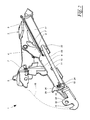
- FIG. 1 shows a coupling device 1 for a motor vehicle, not shown, in particular a tractor.
- a frame 3 of the coupling device 1 is held stationary on the underside, which is formed from lateral cheeks 4 and transverse stiffeners 5.
- bearings 7 are provided for the pivotal support of two front link 8 and two rear link 9.
- pivot bearings 11 are provided, via which a coupling support 12 is pivotally mounted on the links 8, 9.
- a clutch 13 is releasably held, which is formed by way of example only as a coupling hook. However, it is also conceivable to hold any other form of coupling on the coupling carrier 12. In particular, it is intended to hold on a shaft 14 at both ends different couplings 13, so that the coupling 13 can be adjusted by simply turning the shaft 14 to the intended use.
- a hydraulic cylinder 17 is provided, which engages in the rear end portion 18 of the clutch carrier 12 via a pivot bearing 19.
- the hydraulic cylinder 17 is supported in a pivot bearing 20 which defines a pivot axis 21 arranged in front of the front links 8.
- the hydraulic cylinder 17 has a piston 22 on which a piston rod 23 engages.
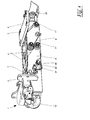
- An end bearing eye 24 of the piston rod 23 detects the clutch carrier 12 indirectly via a lever 25 which is mounted pivotably about an axis 26 in the clutch carrier 12.
- the lever 25 is duplicated. Alternatively, only one lever 25 or more than two levers 25 could be provided. In addition, it passes through a kidney-shaped opening 27 of the coupling carrier 12. This kidney-shaped opening 27 is designed such that it allows a pivoting of the lever 25 by a limited pivoting angle.
- the pivot bearing 19 for the engagement of the bearing eye 24 is arranged on the lever 25.
- the hydraulic cylinder 17 serves both for pivoting the lever 25 and for the direct adjustment of the coupling support 12th
- a locking cam 28 is pivotally supported on the coupling support 12. This locking cam 28 is held pivotable about a pivot axis 29 and is biased by a spring 30 in the illustrated blocking position.
- an abutment 31 is provided for this purpose, which cooperates in the blocking position with the locking cam 28.
- a flange 32 is also provided which has an opening 33. Instead of an opening 33, a bulge or the like could alternatively be provided.
- the flange 32 with its opening 33 cooperates with a locking device 34, which has a non-illustrated, displaceable bolt. This bolt can be moved so that it passes through the opening 33 of the flange 32 in a blocking position and in this way locks the coupling device 1. An accidental lowering of the coupling device 1 in the in FIG. 1 Coupling position shown is thereby reliably prevented even in case of failure of the entire hydraulic system.
- the drawbar is first connected to the clutch 13, which is due to their, lowered on a roadway and far behind a rear end of the vehicle reaching back position easily and without much effort.
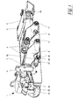
- the coupling carrier 12 is pivoted by means of the hydraulic cylinder 17, wherein the coupling 13 is adjusted by the articulation of the front 8 and rear link 9 along the track 16.
- the coupling 13 is therefore initially with the drawbar of the trailer held thereon raised and then additionally moved up and forward until they reach the in FIG. 3 shown triggering position near the vehicle rear occupies.
- the lever 25 acts for the hydraulic cylinder 17 as a gear 38.
- This gear 38 has the task of lifting the clutch carrier 12 in the last piece of the web 16 in the region of FIG. 5 To effect coupling shown. Since in this position, the hydraulic cylinder 17 is almost exactly perpendicular to the web 16, the hydraulic cylinder 17 could not cause this adjustment movement without the gear 38.
Landscapes
- Engineering & Computer Science (AREA)
- Transportation (AREA)
- Mechanical Engineering (AREA)
- Agricultural Machines (AREA)
- Hydraulic Clutches, Magnetic Clutches, Fluid Clutches, And Fluid Joints (AREA)
Abstract
Description
Die Erfindung betrifft eine Kupplungsvorrichtung für ein Kraftfahrzeug, insbesondere für einen Ackerschlepper gemäß dem Oberbegriff des Patentanspruchs 1.The invention relates to a coupling device for a motor vehicle, in particular for an agricultural tractor according to the preamble of
Aus der
Aus der
Der Erfindung liegt die Aufgabe zugrunde, einen Kupplungsträger der eingangs genannten Art zu schaffen, die einfach zu betätigen ist, wobei der Zugang zu elektrischen bzw. hydraulischen Anschlüssen des Kraftfahrzeugs in keiner Weise behindert wird.The invention has for its object to provide a coupling support of the type mentioned, which is easy to operate, with access to electrical or hydraulic connections of the motor vehicle is in no way hindered.
Diese Aufgabe wird erfindungsgemäß mit den Merkmalen des Patentanspruchs 1 gelöst.This object is achieved with the features of
Die Kupplungsvorrichtung gemäß Anspruch 1 weist mindestens einen hinteren und vorderen Lenker auf, an deren Enden ein Kupplungsträger gelenkig gehalten ist. Diese, im Allgemeinen als "Hitch" bezeichnete Anordnung, gestattet ein Absenken und Anheben einer am Kupplungsträger gehaltenen Kupplung. Diese Kupplung wird dabei entlang einer von den Lenkern und dem Kupplungsträger bestimmten Bahn verstellt, die, ausgehend von einer abgesenkten Stellung, zunächst im Wesentlichen nach oben und anschließend nach vorne und oben verläuft. Eine schwere Deichsel eines Anhängers wird daher von der Kupplungsvorrichtung angehoben, ohne dass hierzu Muskelkraft erforderlich wäre. Insbesondere bei schweren Deichseln, wie sie beispielsweise bei Einachsanhängern vorkommen, ist dies von besonderer Bedeutung, da diese sonst so lange in angehobener Stellung gehalten werden müssten, bis der Ackerschlepper in die korrekte Lage rangiert wurde, so dass die Deichsel mit der Kupplung verbunden werden kann. Dies ist bei der erfindungsgemäßen Ausbildung der Kupplungsvorrichtung nicht erforderlich, so dass der Ankupplungsvorgang insbesondere auch von einer einzigen Person mit geringstem Einsatz an Muskelkraft durchgeführt werden kann. Die Verstellung des Kupplungsträgers erfolgt deshalb durch mindestens einen Hydraulikzylinder. Dieser Hydraulikzylinder ist am Kupplungsträger angelenkt, um diesen zu verstellen.The coupling device according to
Um den Zugang zu heckseitigen Anschlüssen des Ackerschleppers nicht zu beeinträchtigen, ist der mindestens eine Hydraulikzylinder an einer fahrzeugfesten Schwenkachse angelenkt, welche sich vor dem mindestens einen vorderen Lenker befindet. Damit kann der mindestens eine Hydraulikzylinder platzsparend innerhalb des Kupplungsträgers untergebracht werden, wo er die Bedienung des Kraftfahrzeugs in keiner Weise beeinträchtigt. Problematisch an dieser platzsparenden Unterbringung des mindestens einen Hydraulikzylinders ist jedoch, dass insbesondere nahe der angehobenen Kuppelstellung der mindestens eine Hydraulikzylinder nahezu senkrecht zur Bewegungsrichtung des Kupplungsträgers gerichtet ist. Dies führt zu einer sehr ungünstigen Krafteinkopplung, so dass der mindestens eine Hydraulikzylinder nahe der Kupppelstellung des Kupplungsträgers in der Regel nicht mehr die erforderliche Verstellkraft aufbringt. Der mindestens eine Hydraulikzylinder müsste daher beträchtlich überdimensioniert werden, was wiederum zu zusätzlichen Kosten und weiteren Platzproblemen führte.In order not to impair the access to rear-side connections of the tractor, the at least one hydraulic cylinder is articulated to a vehicle-fixed pivot axis, which is located in front of the at least one front link. Thus, the at least one hydraulic cylinder can be accommodated to save space within the clutch carrier, where it does not affect the operation of the motor vehicle in any way. However, the problem with this space-saving accommodation of the at least one hydraulic cylinder is that, in particular near the raised coupling position of the at least one hydraulic cylinder is directed almost perpendicular to the direction of movement of the coupling carrier. This leads to a very unfavorable force input, so that the at least one hydraulic cylinder near the coupling position of the coupling carrier usually no longer applies the required adjusting force. The at least one hydraulic cylinder would therefore have to be oversized considerably, which in turn led to additional costs and space problems.
Zur Lösung dieses Problems wird vorgeschlagen, dass der mindestens eine Hydraulikzylinder den Kupplungsträger über mindestens ein Getriebe erfasst. Dieses Getriebe steht dabei mit mindestens einem fahrzeugfesten Widerlager in Kraft übertragender Wirkverbindung. Damit kann der mindestens eine Hydraulikzylinder den Kupplungsträger einerseits unmittelbar und andererseits mittelbar über das mindestens eine Getriebe und das Widerlager betätigen. Damit kann der kritische Teil des Weges des Kupplungsträgers mit ungünstiger Krafteinkopplung durch das mindestens eine Getriebe bewerkstelligt werden. Auf diese Weise kann der mindestens eine Hydraulikzylinder platzsparend untergebracht werden, ohne Probleme mit der Verstellung des Kupplungsträgers in Kauf nehmen zu müssen.To solve this problem, it is proposed that the at least one hydraulic cylinder detects the clutch carrier via at least one transmission. This gearbox stands with at least one vehicle-fixed abutment in force transmitting operative connection. Thus, the at least one hydraulic cylinder can actuate the clutch carrier, on the one hand, directly and, on the other hand, indirectly via the at least one transmission and the abutment. Thus, the critical part of the path of the coupling carrier can be accomplished with unfavorable force input through the at least one transmission. In this way, the at least one hydraulic cylinder can be accommodated to save space without having to put up with problems with the adjustment of the coupling carrier in purchasing.
Gemäß Anspruch 2 ist es vorteilhaft, wenn das mindestens eine Getriebe mindestens einen am Kupplungsträger angelenkten Hebel aufweist, der mit dem mindestens einen Widerlager in Wirkverbindung steht. Vorzugsweise ist dieser mindestens eine Hebel klauenartig ausgebildet, um eine vom mindestens einen Hydraulikzylinder hervorgerufene Schwenkbewegung in die gewünschte Hebebewegung des Kupplungsträgers umzusetzen. Auf diese Weise ergibt sich ein sehr einfacher mechanischer Aufbau mit günstiger Krafteinwirkung des mindestens einen Hydraulikzylinders.According to claim 2, it is advantageous if the at least one transmission has at least one lever articulated on the coupling carrier, which is in operative connection with the at least one abutment. Preferably, this at least one lever is designed claw-like, to one caused by at least one hydraulic cylinder To implement pivoting movement in the desired lifting movement of the coupling carrier. In this way, results in a very simple mechanical structure with favorable force of the at least one hydraulic cylinder.
Um zu verhindern, dass der mindestens eine Hebel im Schwenkbereich des Kupplungsträgers nahe der abgesenkten Ankuppelstellung des Kupplungsträgers verschwenkt wird, ist es gemäß Anspruch 3 günstig, wenn der mindestens eine Hebel mit mindestens einer Sperrnocke in Wirkverbindung steht. Diese mindestens eine Sperrnocke verhindert ein Verschwenken des mindestens einen Hebels, vorzugsweise bis der mindestens eine Hebel mit dem mindestens einen Widerlager zusammenwirken kann.In order to prevent that the at least one lever is pivoted in the swivel range of the coupling carrier near the lowered Ankuppelstellung the coupling carrier, it is favorable according to
Da der mindestens eine Hebel nur zum Verschwenken des Kupplungsträgers nahe der angehobenen Endstellung - im folgenden Kuppelstellung genannt - benötigt wird, sperrt die mindestens eine Sperrnocke den mindestens einen Hebel nahe der abgesenkten Stellung des Kupplungsträgers und gibt ihn nur nahe der angehobenen Kuppelstellung des Kupplungsträgers frei. Damit ist sichergestellt, dass der mindestens eine Hebel nicht vorzeitig vom mindestens einen Hydraulikzylinder verschwenkt wird, so dass der Schwenkwinkel des mindestens einen Hebels für die kritische letzte Phase des Hebevorgangs des Kupplungsträgers zur Verfügung steht.Since the at least one lever only for pivoting of the coupling carrier near the raised end position - hereinafter called coupling position - is required, locks the at least one locking cam the at least one lever near the lowered position of the coupling carrier and releases it only near the raised coupling position of the coupling carrier. This ensures that the at least one lever is not prematurely pivoted by the at least one hydraulic cylinder, so that the pivot angle of the at least one lever is available for the critical final phase of the lifting operation of the clutch carrier.
Gemäß Anspruch 5 ist es vorteilhaft, wenn der mindestens eine Hebel mit mindestens einer Betätigungsnocke in Wirkverbindung steht, welche am mindestens einen hinteren Lenker und/oder Fahrzeug fest vorgesehen ist. Damit wird die Freigabe des mindestens einen Hebels durch die mindestens eine Nocke selbsttätig bei einer vorgegebenen Stellung des Kupplungsträgers durchgeführt. Hierzu sind keine weiteren Stellmittel erforderlich.According to
Um sicherzustellen, dass sich die mindestens eine Sperrnocke in abgesenkter Stellung des Kupplungsträgers stets in der Sperrstellung befindet, ist diese gemäß Anspruch 6 federnd in die Sperrstellung vorgespannt. Die Federkraft ist dabei derart bemessen, dass die mindestens eine Sperrnocke durch die mindestens eine Betätigungsnocke verstellbar bleibt.To ensure that the at least one locking cam in the lowered position of the coupling carrier is always in the blocking position, this is resiliently biased according to claim 6 in the blocking position. The spring force is dimensioned such that the at least one locking cam remains adjustable by the at least one actuating cam.
Der Erfindungsgegenstand wird beispielhaft anhand der Zeichnung erläutert, ohne den Schutzumfang zu beschränken.The subject invention is exemplified with reference to the drawing, without limiting the scope.
Es zeigt:
Figur 1- eine räumliche Darstellung einer Kupplungsvorrichtung mit abgesenktem Kupplungsträger,
- Figur 2
- eine Schnittdarstellung gemäß
Figur 1 Figur 3- die Darstellung gemäß
Figur 1 Figur 4- die Darstellung gemäß
Figur 3 Figur 5- eine Schnittdarstellung gemäß
Figur 4
- FIG. 1
- a spatial representation of a coupling device with lowered coupling carrier,
- FIG. 2
- a sectional view according to
FIG. 1 . - FIG. 3
- the representation according to
FIG. 1 in a partially raised position of the coupling carrier, - FIG. 4
- the representation according to
FIG. 3 with raised coupling carrier and - FIG. 5
- a sectional view according to
FIG. 4 ,
Am Kraftfahrzeug, insbesondere an dessen Getriebekasten ist unterseitig ein Rahmen 3 der Kupplungsvorrichtung 1 stationär gehalten, der aus seitlichen Wangen 4 und Querversteifungen 5 gebildet ist. An diesem Rahmen 3 sind Lager 7 zur schwenkbaren Abstützung zweier vorderer Lenker 8 und zweier hinterer Lenker 9 vorgesehen. Im Bereich der freien Enden 10 der Lenker 8, 9 sind Schwenklager 11 vorgesehen, über die ein Kupplungsträger 12 an den Lenkern 8, 9 schwenkbar gehalten ist.On the motor vehicle, in particular on its gear box, a
Im Kupplungsträger 12 ist eine Kupplung 13 lösbar gehalten, die lediglich beispielhaft als Kupplungshaken ausgebildet ist. Es ist jedoch auch vorstellbar, jede beliebige andere Kupplungsform am Kupplungsträger 12 zu halten. Es ist insbesondere daran gedacht, an einem Schaft 14 beidendig unterschiedliche Kupplungen 13 zu halten, so dass die Kupplung 13 durch einfaches Umdrehen des Schaftes 14 dem vorgesehenen Verwendungszweck angepasst werden kann.In the
Durch die besondere Aufhängung des Kupplungsträgers 12 an den vorderen 8 und hinteren Lenkern 9 wird erreicht, dass beim Verschwenken dieser Lenker 8, 9 in Verstellrichtung 15 die Kupplung 13 entlang einer Bahn 16 verstellt wird, die ausgehend von der in
Zur Verstellung des Kupplungsträgers 12 ist ein Hydraulikzylinder 17 vorgesehen, der im hinteren Endbereich 18 des Kupplungsträgers 12 über ein Schwenklager 19 angreift. Der Hydraulikzylinder 17 ist in einem Schwenklager 20 abgestützt, welches eine vor den vorderen Lenkern 8 angeordnete Schwenkachse 21 definiert.For adjusting the
Insbesondere aus der Schnittdarstellung gemäß
Aus der räumlichen Darstellung gemäß
Um zu verhindern, dass die Hebel 25 bereits in der dargestellten Ankuppelstellung bei abgesenktem Kupplungsträger 12 vom Hydraulikzylinder 17 verschwenkt werden, ist am Kupplungsträger 12 eine Sperrnocke 28 verschwenkbar abgestützt. Diese Sperrnocke 28 ist um eine Schwenkachse 29 verschwenkbar gehalten und wird von einer Feder 30 in die dargestellte Sperrstellung vorgespannt. Am Schwenklager 19 ist zu diesem Zweck ein Gegenlager 31 vorgesehen, welches in der Sperrstellung mit der Sperrnocke 28 zusammenwirkt. Hierdurch wird jegliche Verschwenkung der Hebel 25 beim Anziehen des Hydraulikzylinders 17 verhindert.In order to prevent the
Am Kupplungsglied 13 ist außerdem ein Flansch 32 vorgesehen, der eine Öffnung 33 aufweist. Statt einer Öffnung 33 könnte alternativ auch eine Ausbuchtung oder dgl. vorgesehen sein. Der Flansch 32 mit seiner Öffnung 33 wirkt mit einer Arretiervorrichtung 34 zusammen, welche einen nicht dargestellten, verschiebbaren Bolzen aufweist. Dieser Bolzen lässt sich derart verschieben, dass er in einer Sperrstellung die Öffnung 33 des Flansches 32 durchsetzt und auf diese Weise die Kupplungsvorrichtung 1 verriegelt. Ein versehentliches Absenken der Kupplungsvorrichtung 1 in die in
Um an das Kraftfahrzeug einen Anhänger anzukuppeln, wird dessen Deichsel zunächst mit der Kupplung 13 verbunden, was aufgrund deren, auf eine Fahrbahn abgesenkten und weit hinter ein Heck des Kraftfahrzeugs zurückreichenden Lage einfach und ohne größeren Kraftaufwand durchführbar ist. Anschließend wird der Kupplungsträger 12 mittels des Hydraulikzylinders 17 verschwenkt, wobei die Kupplung 13 durch die Anlenkung der vorderen 8 und hinteren Lenker 9 entlang der Bahn 16 verstellt wird. Die Kupplung 13 wird daher zunächst mit der daran gehaltenen Deichsel des Anhängers angehoben und anschließend zusätzlich nach oben und vorne verschoben, bis sie die in
In der Auslöse-Lage des Kupplungsträgers 12 gemäß
Der Hebel 25 wirkt dabei für den Hydraulikzylinder 17 als Getriebe 38. Dieses Getriebe 38 hat die Aufgabe, das Anheben des Kupplungsträgers 12 im letzten Stück der Bahn 16 im Bereich der in
Claims (6)
Applications Claiming Priority (1)
| Application Number | Priority Date | Filing Date | Title |
|---|---|---|---|
| DE201220008848 DE202012008848U1 (en) | 2012-09-17 | 2012-09-17 | Coupling device for a motor vehicle |
Publications (4)
| Publication Number | Publication Date |
|---|---|
| EP2708386A2 true EP2708386A2 (en) | 2014-03-19 |
| EP2708386A3 EP2708386A3 (en) | 2015-01-07 |
| EP2708386B1 EP2708386B1 (en) | 2016-07-13 |
| EP2708386B8 EP2708386B8 (en) | 2016-09-21 |
Family
ID=49226000
Family Applications (1)
| Application Number | Title | Priority Date | Filing Date |
|---|---|---|---|
| EP13004475.3A Active EP2708386B8 (en) | 2012-09-17 | 2013-09-13 | Coupling device for a motor vehicle |
Country Status (2)
| Country | Link |
|---|---|
| EP (1) | EP2708386B8 (en) |
| DE (1) | DE202012008848U1 (en) |
Families Citing this family (6)
| Publication number | Priority date | Publication date | Assignee | Title |
|---|---|---|---|---|
| EP3379222B1 (en) | 2017-03-22 | 2020-12-30 | Methode Electronics Malta Ltd. | Magnetoelastic based sensor assembly |
| US11221262B2 (en) | 2018-02-27 | 2022-01-11 | Methode Electronics, Inc. | Towing systems and methods using magnetic field sensing |
| WO2019168565A1 (en) | 2018-02-27 | 2019-09-06 | Methode Electronics,Inc. | Towing systems and methods using magnetic field sensing |
| US11084342B2 (en) | 2018-02-27 | 2021-08-10 | Methode Electronics, Inc. | Towing systems and methods using magnetic field sensing |
| US11135882B2 (en) | 2018-02-27 | 2021-10-05 | Methode Electronics, Inc. | Towing systems and methods using magnetic field sensing |
| US11491832B2 (en) | 2018-02-27 | 2022-11-08 | Methode Electronics, Inc. | Towing systems and methods using magnetic field sensing |
Citations (2)
| Publication number | Priority date | Publication date | Assignee | Title |
|---|---|---|---|---|
| EP0346885B1 (en) | 1988-06-16 | 1992-03-25 | Roman Johann Sauermann | Apparatus for attaching a trailer to a vehicle |
| EP1099575B1 (en) | 1999-11-09 | 2004-02-11 | Hans Sauermann | Coupling device for an automotive vehicle |
Family Cites Families (4)
| Publication number | Priority date | Publication date | Assignee | Title |
|---|---|---|---|---|
| US4542913A (en) * | 1984-07-26 | 1985-09-24 | Deere & Company | Pick-up type drawbar assembly |
| GB2380720B (en) * | 2001-10-08 | 2004-10-27 | Bill Bennett Engineering Ltd | Vehicle hitch |
| ITMO20060217A1 (en) * | 2006-07-04 | 2008-01-05 | Cbm Spa | TRACTOR ATTACHMENT FOR TRAILER. |
| DE202008014513U1 (en) * | 2008-10-31 | 2009-01-22 | Sauermann, Hans | Trailer coupling for a vehicle, in particular for a farm tractor |
-
2012
- 2012-09-17 DE DE201220008848 patent/DE202012008848U1/en not_active Expired - Lifetime
-
2013
- 2013-09-13 EP EP13004475.3A patent/EP2708386B8/en active Active
Patent Citations (2)
| Publication number | Priority date | Publication date | Assignee | Title |
|---|---|---|---|---|
| EP0346885B1 (en) | 1988-06-16 | 1992-03-25 | Roman Johann Sauermann | Apparatus for attaching a trailer to a vehicle |
| EP1099575B1 (en) | 1999-11-09 | 2004-02-11 | Hans Sauermann | Coupling device for an automotive vehicle |
Also Published As
| Publication number | Publication date |
|---|---|
| DE202012008848U1 (en) | 2013-12-18 |
| EP2708386A3 (en) | 2015-01-07 |
| EP2708386B8 (en) | 2016-09-21 |
| EP2708386B1 (en) | 2016-07-13 |
Similar Documents
| Publication | Publication Date | Title |
|---|---|---|
| EP2708386B1 (en) | Coupling device for a motor vehicle | |
| DE3439048C2 (en) | Power lift for a lifting device | |
| DE102013207927A1 (en) | Center armrest with crash protection | |
| DE102009033709A1 (en) | Industrial truck with a frame construction | |
| EP1810561A1 (en) | Towing device | |
| EP3636520B1 (en) | Ballasting device and agricultural vehicle | |
| DE102007045912A1 (en) | Agricultural vehicle | |
| EP2576314B1 (en) | Closure for railway switch actuating devices | |
| EP3715154B1 (en) | Trailer device for an agricultural vehicle | |
| DE102022110404A1 (en) | ATTACHMENT FOR FIELD CULTIVATION | |
| EP2901841B1 (en) | Mowing device for a front mounting on an agricultural towing vehicle | |
| DE102004029577A1 (en) | Telescopic power transmission device | |
| EP1659016B1 (en) | Drive assembly for a vehicle part | |
| EP2829662B1 (en) | Front loader assembly | |
| DE10257595B3 (en) | Drawbar coupling for a vehicle, especially a tractor, comprises locking devices for locking a coupling element in the transport position consisting of a support hook | |
| EP1847447B1 (en) | Posts for the loading aperture of a vehicle superstructure | |
| DE1580349A1 (en) | Tractor coupling | |
| DE202008014513U1 (en) | Trailer coupling for a vehicle, in particular for a farm tractor | |
| DE4130829C2 (en) | Towbar for tractors | |
| DE4427399A1 (en) | Tractor towing-hitch | |
| DE3248648C2 (en) | Device for coupling and uncoupling a front loader to an agricultural tractor | |
| EP4079122A1 (en) | Coupling arrangement for an agricultural tractor | |
| DE1943907C (en) | Coupling device for hitching a vehicle, in particular a single-axle semi-trailer, to a tractor with a towing hook | |
| DE1680186A1 (en) | Trailer coupling for a tractor | |
| DE102011014879A1 (en) | Safety device for agricultural implements |
Legal Events
| Date | Code | Title | Description |
|---|---|---|---|
| PUAI | Public reference made under article 153(3) epc to a published international application that has entered the european phase |
Free format text: ORIGINAL CODE: 0009012 |
|
| AK | Designated contracting states |
Kind code of ref document: A2 Designated state(s): AL AT BE BG CH CY CZ DE DK EE ES FI FR GB GR HR HU IE IS IT LI LT LU LV MC MK MT NL NO PL PT RO RS SE SI SK SM TR |
|
| AX | Request for extension of the european patent |
Extension state: BA ME |
|
| PUAL | Search report despatched |
Free format text: ORIGINAL CODE: 0009013 |
|
| AK | Designated contracting states |
Kind code of ref document: A3 Designated state(s): AL AT BE BG CH CY CZ DE DK EE ES FI FR GB GR HR HU IE IS IT LI LT LU LV MC MK MT NL NO PL PT RO RS SE SI SK SM TR |
|
| AX | Request for extension of the european patent |
Extension state: BA ME |
|
| RIC1 | Information provided on ipc code assigned before grant |
Ipc: B60D 1/24 20060101ALI20141204BHEP Ipc: B60D 1/00 20060101ALI20141204BHEP Ipc: B60D 1/46 20060101ALI20141204BHEP Ipc: B60D 1/04 20060101AFI20141204BHEP |
|
| 17P | Request for examination filed |
Effective date: 20150630 |
|
| RBV | Designated contracting states (corrected) |
Designated state(s): AL AT BE BG CH CY CZ DE DK EE ES FI FR GB GR HR HU IE IS IT LI LT LU LV MC MK MT NL NO PL PT RO RS SE SI SK SM TR |
|
| GRAP | Despatch of communication of intention to grant a patent |
Free format text: ORIGINAL CODE: EPIDOSNIGR1 |
|
| INTG | Intention to grant announced |
Effective date: 20160126 |
|
| GRAS | Grant fee paid |
Free format text: ORIGINAL CODE: EPIDOSNIGR3 |
|
| GRAA | (expected) grant |
Free format text: ORIGINAL CODE: 0009210 |
|
| AK | Designated contracting states |
Kind code of ref document: B1 Designated state(s): AL AT BE BG CH CY CZ DE DK EE ES FI FR GB GR HR HU IE IS IT LI LT LU LV MC MK MT NL NO PL PT RO RS SE SI SK SM TR |
|
| REG | Reference to a national code |
Ref country code: GB Ref legal event code: FG4D Free format text: NOT ENGLISH |
|
| REG | Reference to a national code |
Ref country code: AT Ref legal event code: REF Ref document number: 811961 Country of ref document: AT Kind code of ref document: T Effective date: 20160715 Ref country code: CH Ref legal event code: EP |
|
| GRAT | Correction requested after decision to grant or after decision to maintain patent in amended form |
Free format text: ORIGINAL CODE: EPIDOSNCDEC |
|
| REG | Reference to a national code |
Ref country code: DE Ref legal event code: R081 Ref document number: 502013003651 Country of ref document: DE Owner name: SAUERMANN, FRANZ, DE Free format text: FORMER OWNER: SAUERMANN, HANS, 86558 HOHENWART, DE |
|
| REG | Reference to a national code |
Ref country code: IE Ref legal event code: FG4D Free format text: LANGUAGE OF EP DOCUMENT: GERMAN |
|
| REG | Reference to a national code |
Ref country code: DE Ref legal event code: R082 Ref document number: 502013003651 Country of ref document: DE Representative=s name: TBK, DE |
|
| RAP2 | Party data changed (patent owner data changed or rights of a patent transferred) |
Owner name: SAUERMANN, FRANZ |
|
| RIN2 | Information on inventor provided after grant (corrected) |
Inventor name: SAUERMANN HANS |
|
| REG | Reference to a national code |
Ref country code: DE Ref legal event code: R096 Ref document number: 502013003651 Country of ref document: DE |
|
| REG | Reference to a national code |
Ref country code: FR Ref legal event code: PLFP Year of fee payment: 4 |
|
| REG | Reference to a national code |
Ref country code: SE Ref legal event code: TRGR |
|
| REG | Reference to a national code |
Ref country code: SE Ref legal event code: RPOT |
|
| REG | Reference to a national code |
Ref country code: LT Ref legal event code: MG4D |
|
| REG | Reference to a national code |
Ref country code: NL Ref legal event code: MP Effective date: 20160713 |
|
| REG | Reference to a national code |
Ref country code: GB Ref legal event code: 732E Free format text: REGISTERED BETWEEN 20161110 AND 20161116 |
|
| PG25 | Lapsed in a contracting state [announced via postgrant information from national office to epo] |
Ref country code: HR Free format text: LAPSE BECAUSE OF FAILURE TO SUBMIT A TRANSLATION OF THE DESCRIPTION OR TO PAY THE FEE WITHIN THE PRESCRIBED TIME-LIMIT Effective date: 20160713 Ref country code: NL Free format text: LAPSE BECAUSE OF FAILURE TO SUBMIT A TRANSLATION OF THE DESCRIPTION OR TO PAY THE FEE WITHIN THE PRESCRIBED TIME-LIMIT Effective date: 20160713 Ref country code: IS Free format text: LAPSE BECAUSE OF FAILURE TO SUBMIT A TRANSLATION OF THE DESCRIPTION OR TO PAY THE FEE WITHIN THE PRESCRIBED TIME-LIMIT Effective date: 20161113 Ref country code: LT Free format text: LAPSE BECAUSE OF FAILURE TO SUBMIT A TRANSLATION OF THE DESCRIPTION OR TO PAY THE FEE WITHIN THE PRESCRIBED TIME-LIMIT Effective date: 20160713 Ref country code: RS Free format text: LAPSE BECAUSE OF FAILURE TO SUBMIT A TRANSLATION OF THE DESCRIPTION OR TO PAY THE FEE WITHIN THE PRESCRIBED TIME-LIMIT Effective date: 20160713 Ref country code: NO Free format text: LAPSE BECAUSE OF FAILURE TO SUBMIT A TRANSLATION OF THE DESCRIPTION OR TO PAY THE FEE WITHIN THE PRESCRIBED TIME-LIMIT Effective date: 20161013 |
|
| PG25 | Lapsed in a contracting state [announced via postgrant information from national office to epo] |
Ref country code: GR Free format text: LAPSE BECAUSE OF FAILURE TO SUBMIT A TRANSLATION OF THE DESCRIPTION OR TO PAY THE FEE WITHIN THE PRESCRIBED TIME-LIMIT Effective date: 20161014 Ref country code: ES Free format text: LAPSE BECAUSE OF FAILURE TO SUBMIT A TRANSLATION OF THE DESCRIPTION OR TO PAY THE FEE WITHIN THE PRESCRIBED TIME-LIMIT Effective date: 20160713 Ref country code: PT Free format text: LAPSE BECAUSE OF FAILURE TO SUBMIT A TRANSLATION OF THE DESCRIPTION OR TO PAY THE FEE WITHIN THE PRESCRIBED TIME-LIMIT Effective date: 20161114 Ref country code: PL Free format text: LAPSE BECAUSE OF FAILURE TO SUBMIT A TRANSLATION OF THE DESCRIPTION OR TO PAY THE FEE WITHIN THE PRESCRIBED TIME-LIMIT Effective date: 20160713 Ref country code: BE Free format text: LAPSE BECAUSE OF NON-PAYMENT OF DUE FEES Effective date: 20160930 Ref country code: LV Free format text: LAPSE BECAUSE OF FAILURE TO SUBMIT A TRANSLATION OF THE DESCRIPTION OR TO PAY THE FEE WITHIN THE PRESCRIBED TIME-LIMIT Effective date: 20160713 |
|
| REG | Reference to a national code |
Ref country code: DE Ref legal event code: R097 Ref document number: 502013003651 Country of ref document: DE |
|
| PG25 | Lapsed in a contracting state [announced via postgrant information from national office to epo] |
Ref country code: RO Free format text: LAPSE BECAUSE OF FAILURE TO SUBMIT A TRANSLATION OF THE DESCRIPTION OR TO PAY THE FEE WITHIN THE PRESCRIBED TIME-LIMIT Effective date: 20160713 Ref country code: MC Free format text: LAPSE BECAUSE OF FAILURE TO SUBMIT A TRANSLATION OF THE DESCRIPTION OR TO PAY THE FEE WITHIN THE PRESCRIBED TIME-LIMIT Effective date: 20160713 Ref country code: EE Free format text: LAPSE BECAUSE OF FAILURE TO SUBMIT A TRANSLATION OF THE DESCRIPTION OR TO PAY THE FEE WITHIN THE PRESCRIBED TIME-LIMIT Effective date: 20160713 |
|
| REG | Reference to a national code |
Ref country code: CH Ref legal event code: PL |
|
| PLBE | No opposition filed within time limit |
Free format text: ORIGINAL CODE: 0009261 |
|
| STAA | Information on the status of an ep patent application or granted ep patent |
Free format text: STATUS: NO OPPOSITION FILED WITHIN TIME LIMIT |
|
| PG25 | Lapsed in a contracting state [announced via postgrant information from national office to epo] |
Ref country code: SK Free format text: LAPSE BECAUSE OF FAILURE TO SUBMIT A TRANSLATION OF THE DESCRIPTION OR TO PAY THE FEE WITHIN THE PRESCRIBED TIME-LIMIT Effective date: 20160713 Ref country code: SM Free format text: LAPSE BECAUSE OF FAILURE TO SUBMIT A TRANSLATION OF THE DESCRIPTION OR TO PAY THE FEE WITHIN THE PRESCRIBED TIME-LIMIT Effective date: 20160713 Ref country code: DK Free format text: LAPSE BECAUSE OF FAILURE TO SUBMIT A TRANSLATION OF THE DESCRIPTION OR TO PAY THE FEE WITHIN THE PRESCRIBED TIME-LIMIT Effective date: 20160713 Ref country code: BG Free format text: LAPSE BECAUSE OF FAILURE TO SUBMIT A TRANSLATION OF THE DESCRIPTION OR TO PAY THE FEE WITHIN THE PRESCRIBED TIME-LIMIT Effective date: 20161013 Ref country code: CZ Free format text: LAPSE BECAUSE OF FAILURE TO SUBMIT A TRANSLATION OF THE DESCRIPTION OR TO PAY THE FEE WITHIN THE PRESCRIBED TIME-LIMIT Effective date: 20160713 |
|
| 26N | No opposition filed |
Effective date: 20170418 |
|
| PG25 | Lapsed in a contracting state [announced via postgrant information from national office to epo] |
Ref country code: LI Free format text: LAPSE BECAUSE OF NON-PAYMENT OF DUE FEES Effective date: 20160930 Ref country code: CH Free format text: LAPSE BECAUSE OF NON-PAYMENT OF DUE FEES Effective date: 20160930 |
|
| PG25 | Lapsed in a contracting state [announced via postgrant information from national office to epo] |
Ref country code: SI Free format text: LAPSE BECAUSE OF FAILURE TO SUBMIT A TRANSLATION OF THE DESCRIPTION OR TO PAY THE FEE WITHIN THE PRESCRIBED TIME-LIMIT Effective date: 20160713 Ref country code: LU Free format text: LAPSE BECAUSE OF NON-PAYMENT OF DUE FEES Effective date: 20160913 |
|
| REG | Reference to a national code |
Ref country code: FR Ref legal event code: PLFP Year of fee payment: 5 |
|
| REG | Reference to a national code |
Ref country code: BE Ref legal event code: MM Effective date: 20160930 |
|
| PG25 | Lapsed in a contracting state [announced via postgrant information from national office to epo] |
Ref country code: CY Free format text: LAPSE BECAUSE OF FAILURE TO SUBMIT A TRANSLATION OF THE DESCRIPTION OR TO PAY THE FEE WITHIN THE PRESCRIBED TIME-LIMIT Effective date: 20160713 Ref country code: HU Free format text: LAPSE BECAUSE OF FAILURE TO SUBMIT A TRANSLATION OF THE DESCRIPTION OR TO PAY THE FEE WITHIN THE PRESCRIBED TIME-LIMIT; INVALID AB INITIO Effective date: 20130913 |
|
| PG25 | Lapsed in a contracting state [announced via postgrant information from national office to epo] |
Ref country code: MK Free format text: LAPSE BECAUSE OF FAILURE TO SUBMIT A TRANSLATION OF THE DESCRIPTION OR TO PAY THE FEE WITHIN THE PRESCRIBED TIME-LIMIT Effective date: 20160713 Ref country code: MT Free format text: LAPSE BECAUSE OF FAILURE TO SUBMIT A TRANSLATION OF THE DESCRIPTION OR TO PAY THE FEE WITHIN THE PRESCRIBED TIME-LIMIT Effective date: 20160713 |
|
| REG | Reference to a national code |
Ref country code: FR Ref legal event code: PLFP Year of fee payment: 6 |
|
| PG25 | Lapsed in a contracting state [announced via postgrant information from national office to epo] |
Ref country code: AL Free format text: LAPSE BECAUSE OF FAILURE TO SUBMIT A TRANSLATION OF THE DESCRIPTION OR TO PAY THE FEE WITHIN THE PRESCRIBED TIME-LIMIT Effective date: 20160713 Ref country code: TR Free format text: LAPSE BECAUSE OF FAILURE TO SUBMIT A TRANSLATION OF THE DESCRIPTION OR TO PAY THE FEE WITHIN THE PRESCRIBED TIME-LIMIT Effective date: 20160713 |
|
| PGFP | Annual fee paid to national office [announced via postgrant information from national office to epo] |
Ref country code: IE Payment date: 20230918 Year of fee payment: 11 Ref country code: GB Payment date: 20230921 Year of fee payment: 11 Ref country code: FI Payment date: 20230918 Year of fee payment: 11 Ref country code: AT Payment date: 20230915 Year of fee payment: 11 |
|
| PGFP | Annual fee paid to national office [announced via postgrant information from national office to epo] |
Ref country code: SE Payment date: 20230921 Year of fee payment: 11 Ref country code: FR Payment date: 20230919 Year of fee payment: 11 Ref country code: DE Payment date: 20230926 Year of fee payment: 11 |
|
| PGFP | Annual fee paid to national office [announced via postgrant information from national office to epo] |
Ref country code: IT Payment date: 20230929 Year of fee payment: 11 |