EP2708191A2 - Dispositif de traitement d'un vaisseau - Google Patents
Dispositif de traitement d'un vaisseau Download PDFInfo
- Publication number
- EP2708191A2 EP2708191A2 EP13196092.4A EP13196092A EP2708191A2 EP 2708191 A2 EP2708191 A2 EP 2708191A2 EP 13196092 A EP13196092 A EP 13196092A EP 2708191 A2 EP2708191 A2 EP 2708191A2
- Authority
- EP
- European Patent Office
- Prior art keywords
- vessel
- catheter
- expandable
- cap
- plug
- Prior art date
- Legal status (The legal status is an assumption and is not a legal conclusion. Google has not performed a legal analysis and makes no representation as to the accuracy of the status listed.)
- Granted
Links
- 230000000903 blocking effect Effects 0.000 claims abstract description 116
- 230000007246 mechanism Effects 0.000 claims abstract description 68
- 238000004873 anchoring Methods 0.000 claims abstract description 42
- 239000003795 chemical substances by application Substances 0.000 claims description 20
- 239000003814 drug Substances 0.000 claims description 9
- 229940079593 drug Drugs 0.000 claims description 9
- 238000011282 treatment Methods 0.000 description 76
- 210000003462 vein Anatomy 0.000 description 52
- 238000000034 method Methods 0.000 description 37
- 238000007632 sclerotherapy Methods 0.000 description 34
- 206010046996 Varicose vein Diseases 0.000 description 29
- 239000003229 sclerosing agent Substances 0.000 description 26
- 238000001356 surgical procedure Methods 0.000 description 24
- 239000008280 blood Substances 0.000 description 20
- 210000004369 blood Anatomy 0.000 description 20
- 238000003780 insertion Methods 0.000 description 20
- 230000037431 insertion Effects 0.000 description 20
- 239000000463 material Substances 0.000 description 19
- 210000003752 saphenous vein Anatomy 0.000 description 19
- 208000027185 varicose disease Diseases 0.000 description 14
- 239000000758 substrate Substances 0.000 description 10
- 238000010992 reflux Methods 0.000 description 7
- 238000000605 extraction Methods 0.000 description 6
- 239000006260 foam Substances 0.000 description 6
- 230000006378 damage Effects 0.000 description 5
- 210000003414 extremity Anatomy 0.000 description 5
- 238000002347 injection Methods 0.000 description 5
- 239000007924 injection Substances 0.000 description 5
- 210000002414 leg Anatomy 0.000 description 5
- 239000002184 metal Substances 0.000 description 5
- 238000011144 upstream manufacturing Methods 0.000 description 5
- 201000002282 venous insufficiency Diseases 0.000 description 5
- 239000002775 capsule Substances 0.000 description 4
- 239000004033 plastic Substances 0.000 description 4
- 206010016654 Fibrosis Diseases 0.000 description 3
- 208000025865 Ulcer Diseases 0.000 description 3
- 210000001367 artery Anatomy 0.000 description 3
- 210000004204 blood vessel Anatomy 0.000 description 3
- 230000008859 change Effects 0.000 description 3
- 201000002816 chronic venous insufficiency Diseases 0.000 description 3
- 230000006835 compression Effects 0.000 description 3
- 238000007906 compression Methods 0.000 description 3
- 230000004761 fibrosis Effects 0.000 description 3
- 238000000608 laser ablation Methods 0.000 description 3
- 238000002647 laser therapy Methods 0.000 description 3
- 239000007788 liquid Substances 0.000 description 3
- 230000007774 longterm Effects 0.000 description 3
- 238000012986 modification Methods 0.000 description 3
- 230000004048 modification Effects 0.000 description 3
- HLXZNVUGXRDIFK-UHFFFAOYSA-N nickel titanium Chemical compound [Ti].[Ti].[Ti].[Ti].[Ti].[Ti].[Ti].[Ti].[Ti].[Ti].[Ti].[Ni].[Ni].[Ni].[Ni].[Ni].[Ni].[Ni].[Ni].[Ni].[Ni].[Ni].[Ni].[Ni].[Ni] HLXZNVUGXRDIFK-UHFFFAOYSA-N 0.000 description 3
- 229910001000 nickel titanium Inorganic materials 0.000 description 3
- -1 polypropylen Polymers 0.000 description 3
- 238000007674 radiofrequency ablation Methods 0.000 description 3
- 230000009467 reduction Effects 0.000 description 3
- 239000005060 rubber Substances 0.000 description 3
- 239000000243 solution Substances 0.000 description 3
- 229910001220 stainless steel Inorganic materials 0.000 description 3
- 239000010935 stainless steel Substances 0.000 description 3
- 208000024891 symptom Diseases 0.000 description 3
- 231100000397 ulcer Toxicity 0.000 description 3
- 238000002604 ultrasonography Methods 0.000 description 3
- 206010051055 Deep vein thrombosis Diseases 0.000 description 2
- 208000005189 Embolism Diseases 0.000 description 2
- 239000004677 Nylon Substances 0.000 description 2
- 206010040943 Skin Ulcer Diseases 0.000 description 2
- 208000007536 Thrombosis Diseases 0.000 description 2
- 206010047249 Venous thrombosis Diseases 0.000 description 2
- 210000003423 ankle Anatomy 0.000 description 2
- 238000013459 approach Methods 0.000 description 2
- 244000309466 calf Species 0.000 description 2
- 150000001875 compounds Chemical class 0.000 description 2
- 239000002537 cosmetic Substances 0.000 description 2
- 230000010102 embolization Effects 0.000 description 2
- 238000005538 encapsulation Methods 0.000 description 2
- 210000003191 femoral vein Anatomy 0.000 description 2
- 230000036541 health Effects 0.000 description 2
- 230000000004 hemodynamic effect Effects 0.000 description 2
- 238000002955 isolation Methods 0.000 description 2
- 229920001778 nylon Polymers 0.000 description 2
- 229920001155 polypropylene Polymers 0.000 description 2
- 210000003513 popliteal vein Anatomy 0.000 description 2
- 230000002685 pulmonary effect Effects 0.000 description 2
- 238000007789 sealing Methods 0.000 description 2
- 230000000087 stabilizing effect Effects 0.000 description 2
- 238000005728 strengthening Methods 0.000 description 2
- 238000002560 therapeutic procedure Methods 0.000 description 2
- 210000001519 tissue Anatomy 0.000 description 2
- 210000000689 upper leg Anatomy 0.000 description 2
- 230000002792 vascular Effects 0.000 description 2
- XKZGIJICHCVXFV-UHFFFAOYSA-N 2-ethylhexyl diphenyl phosphite Chemical compound C=1C=CC=CC=1OP(OCC(CC)CCCC)OC1=CC=CC=C1 XKZGIJICHCVXFV-UHFFFAOYSA-N 0.000 description 1
- 208000031104 Arterial Occlusive disease Diseases 0.000 description 1
- 206010015719 Exsanguination Diseases 0.000 description 1
- 102000009123 Fibrin Human genes 0.000 description 1
- 108010073385 Fibrin Proteins 0.000 description 1
- BWGVNKXGVNDBDI-UHFFFAOYSA-N Fibrin monomer Chemical compound CNC(=O)CNC(=O)CN BWGVNKXGVNDBDI-UHFFFAOYSA-N 0.000 description 1
- 241000628997 Flos Species 0.000 description 1
- 208000032843 Hemorrhage Diseases 0.000 description 1
- 206010019663 Hepatic failure Diseases 0.000 description 1
- 206010020772 Hypertension Diseases 0.000 description 1
- 206010025282 Lymphoedema Diseases 0.000 description 1
- 206010028980 Neoplasm Diseases 0.000 description 1
- 208000008589 Obesity Diseases 0.000 description 1
- 206010030124 Oedema peripheral Diseases 0.000 description 1
- 208000018262 Peripheral vascular disease Diseases 0.000 description 1
- 208000003251 Pruritus Diseases 0.000 description 1
- 208000001647 Renal Insufficiency Diseases 0.000 description 1
- 206010039710 Scleroderma Diseases 0.000 description 1
- 208000000558 Varicose Ulcer Diseases 0.000 description 1
- 238000002679 ablation Methods 0.000 description 1
- 230000000151 anti-reflux effect Effects 0.000 description 1
- 238000003491 array Methods 0.000 description 1
- 238000001266 bandaging Methods 0.000 description 1
- 210000003445 biliary tract Anatomy 0.000 description 1
- 239000000560 biocompatible material Substances 0.000 description 1
- 230000015572 biosynthetic process Effects 0.000 description 1
- 230000036772 blood pressure Effects 0.000 description 1
- 210000004556 brain Anatomy 0.000 description 1
- 239000002561 chemical irritant Substances 0.000 description 1
- 230000001684 chronic effect Effects 0.000 description 1
- 208000012696 congenital leptin deficiency Diseases 0.000 description 1
- 230000001351 cycling effect Effects 0.000 description 1
- 230000023753 dehiscence Effects 0.000 description 1
- 239000003599 detergent Substances 0.000 description 1
- 206010012601 diabetes mellitus Diseases 0.000 description 1
- 201000010099 disease Diseases 0.000 description 1
- 208000037265 diseases, disorders, signs and symptoms Diseases 0.000 description 1
- 238000009552 doppler ultrasonography Methods 0.000 description 1
- 230000004064 dysfunction Effects 0.000 description 1
- 230000002500 effect on skin Effects 0.000 description 1
- 230000003073 embolic effect Effects 0.000 description 1
- 210000003038 endothelium Anatomy 0.000 description 1
- 239000000835 fiber Substances 0.000 description 1
- 229950003499 fibrin Drugs 0.000 description 1
- 210000002683 foot Anatomy 0.000 description 1
- 230000006870 function Effects 0.000 description 1
- 230000002496 gastric effect Effects 0.000 description 1
- 210000005095 gastrointestinal system Anatomy 0.000 description 1
- 239000003292 glue Substances 0.000 description 1
- 239000000383 hazardous chemical Substances 0.000 description 1
- 238000010438 heat treatment Methods 0.000 description 1
- 230000002706 hydrostatic effect Effects 0.000 description 1
- 238000003384 imaging method Methods 0.000 description 1
- 238000011221 initial treatment Methods 0.000 description 1
- 208000014674 injury Diseases 0.000 description 1
- 239000002085 irritant Substances 0.000 description 1
- 231100000021 irritant Toxicity 0.000 description 1
- 230000007803 itching Effects 0.000 description 1
- 201000006370 kidney failure Diseases 0.000 description 1
- 208000007903 liver failure Diseases 0.000 description 1
- 231100000835 liver failure Toxicity 0.000 description 1
- 238000002690 local anesthesia Methods 0.000 description 1
- 210000003141 lower extremity Anatomy 0.000 description 1
- 208000002502 lymphedema Diseases 0.000 description 1
- 230000007257 malfunction Effects 0.000 description 1
- 238000013507 mapping Methods 0.000 description 1
- 230000005012 migration Effects 0.000 description 1
- 238000013508 migration Methods 0.000 description 1
- 208000001022 morbid obesity Diseases 0.000 description 1
- 210000005036 nerve Anatomy 0.000 description 1
- 210000000653 nervous system Anatomy 0.000 description 1
- 210000000056 organ Anatomy 0.000 description 1
- 230000003204 osmotic effect Effects 0.000 description 1
- 230000036407 pain Effects 0.000 description 1
- 208000035824 paresthesia Diseases 0.000 description 1
- 230000000149 penetrating effect Effects 0.000 description 1
- 239000008177 pharmaceutical agent Substances 0.000 description 1
- 238000003825 pressing Methods 0.000 description 1
- 230000002035 prolonged effect Effects 0.000 description 1
- 210000002345 respiratory system Anatomy 0.000 description 1
- 230000002441 reversible effect Effects 0.000 description 1
- 206010039073 rheumatoid arthritis Diseases 0.000 description 1
- 239000010703 silicon Substances 0.000 description 1
- 229910052710 silicon Inorganic materials 0.000 description 1
- 238000006467 substitution reaction Methods 0.000 description 1
- 230000008961 swelling Effects 0.000 description 1
- 208000011580 syndromic disease Diseases 0.000 description 1
- 201000005060 thrombophlebitis Diseases 0.000 description 1
- 230000008733 trauma Effects 0.000 description 1
- 238000012285 ultrasound imaging Methods 0.000 description 1
- 210000002229 urogenital system Anatomy 0.000 description 1
- 238000007666 vacuum forming Methods 0.000 description 1
- 208000037997 venous disease Diseases 0.000 description 1
Images


Classifications
-
- A—HUMAN NECESSITIES
- A61—MEDICAL OR VETERINARY SCIENCE; HYGIENE
- A61F—FILTERS IMPLANTABLE INTO BLOOD VESSELS; PROSTHESES; DEVICES PROVIDING PATENCY TO, OR PREVENTING COLLAPSING OF, TUBULAR STRUCTURES OF THE BODY, e.g. STENTS; ORTHOPAEDIC, NURSING OR CONTRACEPTIVE DEVICES; FOMENTATION; TREATMENT OR PROTECTION OF EYES OR EARS; BANDAGES, DRESSINGS OR ABSORBENT PADS; FIRST-AID KITS
- A61F2/00—Filters implantable into blood vessels; Prostheses, i.e. artificial substitutes or replacements for parts of the body; Appliances for connecting them with the body; Devices providing patency to, or preventing collapsing of, tubular structures of the body, e.g. stents
- A61F2/02—Prostheses implantable into the body
-
- A—HUMAN NECESSITIES
- A61—MEDICAL OR VETERINARY SCIENCE; HYGIENE
- A61B—DIAGNOSIS; SURGERY; IDENTIFICATION
- A61B17/00—Surgical instruments, devices or methods, e.g. tourniquets
- A61B17/12—Surgical instruments, devices or methods, e.g. tourniquets for ligaturing or otherwise compressing tubular parts of the body, e.g. blood vessels, umbilical cord
- A61B17/12022—Occluding by internal devices, e.g. balloons or releasable wires
- A61B17/12027—Type of occlusion
- A61B17/1204—Type of occlusion temporary occlusion
- A61B17/12045—Type of occlusion temporary occlusion double occlusion, e.g. during anastomosis
-
- A—HUMAN NECESSITIES
- A61—MEDICAL OR VETERINARY SCIENCE; HYGIENE
- A61B—DIAGNOSIS; SURGERY; IDENTIFICATION
- A61B17/00—Surgical instruments, devices or methods, e.g. tourniquets
- A61B17/12—Surgical instruments, devices or methods, e.g. tourniquets for ligaturing or otherwise compressing tubular parts of the body, e.g. blood vessels, umbilical cord
- A61B17/12022—Occluding by internal devices, e.g. balloons or releasable wires
- A61B17/12099—Occluding by internal devices, e.g. balloons or releasable wires characterised by the location of the occluder
- A61B17/12109—Occluding by internal devices, e.g. balloons or releasable wires characterised by the location of the occluder in a blood vessel
-
- A—HUMAN NECESSITIES
- A61—MEDICAL OR VETERINARY SCIENCE; HYGIENE
- A61B—DIAGNOSIS; SURGERY; IDENTIFICATION
- A61B17/00—Surgical instruments, devices or methods, e.g. tourniquets
- A61B17/12—Surgical instruments, devices or methods, e.g. tourniquets for ligaturing or otherwise compressing tubular parts of the body, e.g. blood vessels, umbilical cord
- A61B17/12022—Occluding by internal devices, e.g. balloons or releasable wires
- A61B17/12131—Occluding by internal devices, e.g. balloons or releasable wires characterised by the type of occluding device
- A61B17/12136—Balloons
-
- A—HUMAN NECESSITIES
- A61—MEDICAL OR VETERINARY SCIENCE; HYGIENE
- A61B—DIAGNOSIS; SURGERY; IDENTIFICATION
- A61B17/00—Surgical instruments, devices or methods, e.g. tourniquets
- A61B17/12—Surgical instruments, devices or methods, e.g. tourniquets for ligaturing or otherwise compressing tubular parts of the body, e.g. blood vessels, umbilical cord
- A61B17/12022—Occluding by internal devices, e.g. balloons or releasable wires
- A61B17/12131—Occluding by internal devices, e.g. balloons or releasable wires characterised by the type of occluding device
- A61B17/12168—Occluding by internal devices, e.g. balloons or releasable wires characterised by the type of occluding device having a mesh structure
- A61B17/12172—Occluding by internal devices, e.g. balloons or releasable wires characterised by the type of occluding device having a mesh structure having a pre-set deployed three-dimensional shape
-
- A—HUMAN NECESSITIES
- A61—MEDICAL OR VETERINARY SCIENCE; HYGIENE
- A61F—FILTERS IMPLANTABLE INTO BLOOD VESSELS; PROSTHESES; DEVICES PROVIDING PATENCY TO, OR PREVENTING COLLAPSING OF, TUBULAR STRUCTURES OF THE BODY, e.g. STENTS; ORTHOPAEDIC, NURSING OR CONTRACEPTIVE DEVICES; FOMENTATION; TREATMENT OR PROTECTION OF EYES OR EARS; BANDAGES, DRESSINGS OR ABSORBENT PADS; FIRST-AID KITS
- A61F2/00—Filters implantable into blood vessels; Prostheses, i.e. artificial substitutes or replacements for parts of the body; Appliances for connecting them with the body; Devices providing patency to, or preventing collapsing of, tubular structures of the body, e.g. stents
- A61F2/01—Filters implantable into blood vessels
-
- A—HUMAN NECESSITIES
- A61—MEDICAL OR VETERINARY SCIENCE; HYGIENE
- A61M—DEVICES FOR INTRODUCING MEDIA INTO, OR ONTO, THE BODY; DEVICES FOR TRANSDUCING BODY MEDIA OR FOR TAKING MEDIA FROM THE BODY; DEVICES FOR PRODUCING OR ENDING SLEEP OR STUPOR
- A61M25/00—Catheters; Hollow probes
- A61M25/01—Introducing, guiding, advancing, emplacing or holding catheters
- A61M25/09—Guide wires
-
- A—HUMAN NECESSITIES
- A61—MEDICAL OR VETERINARY SCIENCE; HYGIENE
- A61B—DIAGNOSIS; SURGERY; IDENTIFICATION
- A61B17/00—Surgical instruments, devices or methods, e.g. tourniquets
- A61B2017/00831—Material properties
- A61B2017/00867—Material properties shape memory effect
-
- A—HUMAN NECESSITIES
- A61—MEDICAL OR VETERINARY SCIENCE; HYGIENE
- A61B—DIAGNOSIS; SURGERY; IDENTIFICATION
- A61B17/00—Surgical instruments, devices or methods, e.g. tourniquets
- A61B17/12—Surgical instruments, devices or methods, e.g. tourniquets for ligaturing or otherwise compressing tubular parts of the body, e.g. blood vessels, umbilical cord
- A61B17/12022—Occluding by internal devices, e.g. balloons or releasable wires
- A61B2017/1205—Introduction devices
- A61B2017/12054—Details concerning the detachment of the occluding device from the introduction device
Definitions
- the present invention relates to methods and devices to enable blockage, occlusion and/or treatment of vessels such as blood vessels, Specifically, embodiments of the present invention relate to devices and methods that may block selected segments of veins or arteries.
- venous system of the lower extremities includes the superficial (greater and lesser saphenous veins) and deep system (popliteal and femoral veins). These two parallel systems are interconnected via perforator veins.
- One-way valves are present at the junctions between the bifurcation point of the deep and superficial system, at the saphenofemoral and the saphenopopliteal junctions.
- varicose veins e.g., tortuous veins measuring between 2 mm and 2 cm in diameter, and protruding above the surface of the skin, are typically related to valve incompetence either at the saphenofemoral or saphenopopliteal junction.
- valve incompetence leads to increased hydrostatic pressure transmitted to the unsupported superficial vein system, ultimately resulting in varicosities.
- Clusters of varicosities may appear at the site of perforating vessels, such as the perforating veins of Hunter and Dodd, located in the mid and distal thigh, respectively. This pattern of varicosity is typically associated with incompetence at the saphenofemoral junction.
- the valvular incompetence may be isolated to a perforator vein, such as the Boyd perforating vein located in the anteromedial calf.
- a perforator vein such as the Boyd perforating vein located in the anteromedial calf.
- These varicosities are often not associated with saphenous vein incompetence since the perforating veins in the lower part of the leg do not communicate directly with the saphenous vein.
- varicose veins are asymptomatic, symptoms including itching, heaviness, and pain may occur.
- varicose veins may be complicated by peripheral edema due to venous insufficiency, hemorrhage, thrombophlebitis, venous ulceration, and chronic skin changes.
- Varicose veins are a common condition. In adult western populations visible varicose veins are present in 20-25% of women and 10-15% of men. In most persons, varicose veins do not cause symptoms other than poor cosmetics. Varicose vein surgery is one of the most commonly performed cosmetic procedures in the United States.
- varicose veins do not require medical treatment (Tapley, et al. 2003). In some cases, however, the circulation may be hindered enough to cause swelling of the foot and ankle, discomfort, a tingling sensation, or a feeling of heaviness. For most people with varicose veins, wearing specially fitted elastic stockings is all that is needed. The stockings should be carefully fitted to the individual, providing the most pressure in the lowest part of the leg. Exercise such as walking or cycling also helps promote better circulation from the lower part of the body. Symptoms often decrease when the legs are elevated periodically, and when prolonged standing is avoided. Varicose veins can usually be treated with non-surgical measures.
- Surgical treatment of varicosities may include controlling the most proximal point of reflux, typically at the saphenofemoral junction, as identified by preoperative Doppler ultrasonography. Surgical ligation and division of the saphenofemoral or saphenopopliteal junction is performed to treat the valvular incompetence.
- Another surgical treatment includes removal of the refluxing greater and/or lesser saphenous vein from the circulation. The most typical strategy for isolation is vein stripping, which is generally preceded by vein ligation and division.
- a further surgical treatment includes removal of the varicose tributaries. Strategies for removal include stab avulsion or injection sclerotherapy, either at the time of the initial treatment, or subsequently.
- sclerotherapy is generally to destroy the endothelium of the target vessel by injecting an irritant solution (for example a detergent, osmotic solution, or a chemical irritant), ultimately resulting in the complete obliteration of the vessel. Too little destruction may lead to thrombosis without fibrosis and ultimate recanalization. Too much destruction may lead to vascular dehiscence.
- an irritant solution for example a detergent, osmotic solution, or a chemical irritant
- Too little destruction may lead to thrombosis without fibrosis and ultimate recanalization. Too much destruction may lead to vascular dehiscence.
- the success of the treatment may depend on accurate injection of the vessel, an adequate injectant volume and concentration of sclerosant, and post-procedure compression.
- sclerotherapy is an accepted and effective treatment of telangiectatic vessels, it has also been used in the treatment of varicose tributaries without prior ligation, with or without vein stripping. This application of sclerotherapy creates issues regarding its effectiveness in the absence of the control of the point of reflux and isolation of the refluxing saphenous vein. In addition, when the sclerosant is injected into the greater or lesser saphenous vein, sclerotherapy has been investigated as a minimally invasive alternative to vein snipping, either with or without ligation.
- echosclerotherapy Since the saphenous vein is not visible with the naked eye, injection is typically guided by ultrasonography, and the combined procedure may be referred to as "echosclerotherapy.” Since the greater saphenous vein is larger and deeper than telangiectatic dermal veins, sclerotherapy of this vein raises issues regarding appropriate volume and concentration of the sclerosant and the ability to provide adequate post-procedure compression. Moreover, the use of sclerotherapy, as opposed to the physical removal of the vein with stripping, raises the issue of recurrence due to recanalization.
- Radiofrequency ablation and laser ablation have been investigated as minimally invasive alternatives to vein ligation and stripping. Both radiofrequency energy and laser therapy are similarly designed to damage the intimal wall of the vessel, resulting in fibrosis and ultimately obliteration of a long segment of the vein. Radiofrequency ablation is generally performed by means of a specially designed catheter inserted through a small incision in the distal medial thigh to within 1-2 cm of the saphenofemoral junction.
- High frequency radio waves 200-300 kHz
- the catheter is slowly withdrawn, closing the vein.
- Laser ablation is performed similarly.
- a bare tipped laser fiber is introduced into the greater saphenous vein under ultrasound guidance; the laser is activated and slowly removed along the course of the saphenous vein.
- Such catheters may generally treat veins with diameters that range from 2 to 12 mm.
- Each catheter may have a microthermocouple to monitor vein wall temperature.
- the catheter with its electrodes sheathed is passed either prograde or retrograde through a venipuncture or through direct surgical exposure of the saphenous vein.
- the catheter position may be confirmed by ultrasound imaging, and exsanguination of the vein may be accomplished by external elastic wrapping (Esmarch bandaging) or large volume, very dilute local anesthesia (tumescent technique).
- SEPS Subfascial endoscopic perforator vein surgery
- Contraindications for SEPS include associated arterial occlusive disease, infected ulcer, a non-ambulatory patient, and a medically high-risk patient.
- Diabetes, renal failure, liver failure, morbid obesity, ulcers in patients with rheumatoid arthritis, or scleroderma, and presence of deep vein obstruction at the level of the popliteal vein or higher on preoperative imaging are relative contraindications.
- Patients with extensive skin changes, circumferential large ulcers, recent deep vein thrombosis, severe lymphedema, or large legs may not be suitable candidates (Kalra and Gloviczki, 2002).
- a vessel blocking device comprising: an expandable concave blocking plug adapted to block a vessel; and an anchoring mechanism having a plurality of catching elements connected to the expandable concave blocking plug and adapted to engage with a vessel wall of the vessel; characterized by: the expandable concave blocking plug being adapted to expand within the vessel and to collapse within the vessel subsequent to the engagement of the plurality of catching elements with the vessel wall.
- the vessel blocking plug is foldable.
- the expandable concave blocking plug has an hourglass shape.
- the expandable concave blocking plug includes a rim, the rim being expandable towards a vessel.
- the expandable concave blocking plug comprises a cap and a base to stabilize the cap in a vessel.
- the device further comprises a pullable mechanism to extract the expandable concave blocking plug device from a vessel.
- the device further comprises an absorbable wire.
- the absorbable wire may be coated with occluding agent.
- the plurality of catching elements comprises a plurality of spikes.
- the plurality of catching elements comprises a plurality of hooks.
- the vessel blocking device is part of a kit that comprises a catheter device.
- the catheter device or kit comprises a guidewire.
- the catheter device or kit comprises a drug dispensing mechanism.
- the catheter device or kit comprises an inner catheter device.
- the engagement of the plurality of catching elements with the vessel wall facilitates fusing the vessel walls together around the expandable concave blocking plug and occluding the vessel.
- a vessel blocking device comprising: an expandable cap to block a vessel; and a base to stabilize the cap in a vessel.
- an expansion element may be disposed between the cap and the base.
- an inflatable balloon may be disposed between the cap and the base.
- the cap or base may partially surround the balloon.
- the blocking device may be located at the distal tip of an insertion device, and the cap may be distal to the insertion device relative to the cap, the balloon being disposed between the cap and the base.
- the cap may be concave, and the cap may be expandable so that a rim of the cap can extend outwards towards vessel walls.
- the base may be expandable outwards towards vessel walls.
- An increase in pressure in the inner portion of the cap may cause the cap to expand outwards towards the vessel walls.
- the pressure may be provided by balloon inflation.
- Pressure stored within the cap may cause the cap to expand outwards towards the vessel walls.
- the pressure may be provided by a stent or a coil like mechanism.
- the base may comprise an anchoring mechanism to anchor the cap to the vessel walls.
- the anchoring mechanism may comprise spikes or hooks
- the device may comprise a pullable mechanism to extract the blocking device from a vessel.
- the device may further comprise an absorbable wire.
- the absorbable wire may be coated with occluding agent.
- the device may further comprise a catheter device.
- the catheter device may comprise any of: a guidewire, a drug dispensing mechanism, and a channel for remotely inflating and deflating the balloon.
- the base may be cap shaped.
- a vessel blocking device comprising: two concave blocking devices, connected at their narrow ends; and an anchoring mechanism.
- the vessel blocking device may be foldable.
- the vessel blocking device may have an hourglass shape.
- the concave devices may each include a rim, the rim being expandable towards a vessel.
- the device may comprise an expansion element to expand a blocking device towards a vessel.
- the device may comprise a pullable mechanism to extract the expandable vessel blocking device from a vessel.
- the device may comprise an absorbable wire, preferably wherein the absorbable wire is coated with occluding agent.
- the device may comprise an anchoring mechanism comprising spikes or hooks.
- the device may further comprise a catheter device.
- the catheter device may comprise any of: a guidewire, a drug dispensing mechanism and an inner catheter device.
- a treatment method comprising: inserting a blocking device into a target vessel, deploying the blocking device to block a treatment area and delivering an occluding agent to the treatment area while controlling pressure in the treatment area.
- Inserting a blocking device may include using an insertion device.
- the insertion device may be a catheter or a capsule.
- Deploying the blocking device may comprise any of: expanding the blocking device to fit vessel walls, anchoring the blocking device to the vessel walls, applying external pressure to the vessel walls to engage the blocking device to the vessel walls, and an absorbable wire to guide and hold the blocking device to a selected location.
- the method may comprise disconnecting and removing unnecessary elements from the vessel using the insertion device.
- the occluding agent may be a sclerosing agent.
- the method may comprise any of: delivering an occluding agent using a catheter, controlling pressure in the treatment area using suction of content from treatment area, and controlling pressure in the treatment area by reduction of pressure in the treatment area.
- Suction of content from the treatment area may be performed using a suction device.
- the suction device may be any of: a pump, a balloon, a syringe.
- the method may comprise controlling pressure in the treatment area using suction of content from the treatment area while delivering an agent to the treatment area.
- Controlling pressure in the treatment area may include maintaining the pressure in treatment area. This may comprise maintaining zero pressure in the treatment area or reducing entry of sclerosing agents into the blood stream, external to the treatment area.
- the method may comprise any of: using as a blocking device two caps connected at their narrow ends, using an expandable ring shaped blocking device, using an expandable figure-8 shaped blocking device, and using an expandable oval shaped blocking device.
- Embodiments of the invention may include an intraluminal device configured to treat complications in vessels, for example bifurcated varicose veins or other damaged vessels, lumen, etc., by selectively blocking off at least part of a vessel using a typically minimally invasive technique.
- a predetermined region e.g., the saphenofemoral region
- the blocked off section of the vessel may be treated using, for example, ligation, heat and/or sclerosing or other suitable agents.
- Other lumens may be occluded or blocked using various embodiments of the present invention.
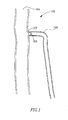
- FIG. 1 schematically illustrates a simplification of part of the human venous system, including a bifurcated vessel 102.
- a saphenous vein 106 extends into a femoral vein 104, via saphenofemoral junction 107.
- a vessel blocking device 108 may be deployed in vessel 102, for example, proximal to the saphenofemoral junction 107, or at other suitable location, to block off at least a part of vessel 106.
- the upstream section of a vein may be blocked off to enable treatment and/or destruction of the blocked portion and/or upstream section of the vein.
- FIG. 2 schematically illustrates a catheter delivery of a vessel blocking device, according to an embodiment of the present invention.
- Vessel blocking device 200 may be inserted, for example, into a target vessel 205 that requires treatment, for example, a bifurcated vessel or an occluded blood segment that is to be blocked and/or otherwise treated.
- a target vessel 205 that requires treatment, for example, a bifurcated vessel or an occluded blood segment that is to be blocked and/or otherwise treated.
- Such insertion of device 200 may be implemented, for example, using an insertion device such as a catheter 210, which may include, for example, a guidewire 230, to help guide device 200 to a selected location.
- Other insertion devices and methods may be used.
- Catheter 210 may include for example a drug dispensing mechanism 215, to enable delivery of a pharmaceutical compound, medication, solution, foam or another suitable agent, such as for example a sclerosing agent, to a target area, via catheter 210.
- Catheter 210 may include a proximal end (not shown, typically towards or at the control end of the catheter 210) and a distal tip 220. Proximal and distal when use herein are relative terms, typically relative to the control end or holding end of catheter 210; e g., proximal is nearer the control or external end.
- the control end e.g. the proximal end
- the control end may be used for holding and operating catheter 210, for example, by a doctor or a health professional.
- Vessel blocking device 200 may include one or more inflatable balloons 240, which may be remotely inflated and/or deflated, for example, by inputting and/or extracting gas and/or liquid via for example an inflation/deflation channel 225. Other or different channels may be used. Other suitable expansion or pressure application elements, other than balloons, may be used. Vessel blocking device 200 may include an extendable or expandable cover or cap 250 that may be extended or expanded so as to block a vessel.
- Cap 250 may encompass, for example, a blocking device, shield, plug, stopper, choke or other device or apparatus to plug up, block or occlude, either partially or completely, a selected lumen or vessel.
- Cap 250 may be concave or bowl shaped and may include a rim 251.
- Cap 250 may be expandable so that rim 251 may extends outwards towards vessel walls when, for example, a pressure is provided inside.
- balloons 240 may be inflated, thereby pressuring cap 250 to extend towards the walls of a vessel 205.
- Cap 250 may be constructed from silicon, plastic, rubber, metal or any other suitable material or combinations of materials.
- cap 250 may be a flexible structure that may be extended, expanded, retracted, shrunk etc. within a vessel or lumen. More than one cap may be used; e.g., caps placed narrow end to narrow end, or wide end to wide end, may be used.
- Vessel blocking device 200 may include a base 260, for example, constructed from stainless steel, rubber, mesh or other suitable materials, to enable stabilizing of cap 250 in a selected location and/or permanent or semi-permanent strengthening of vessel blocking device 200.
- Base 260 may be mechanically bonded to a portion of cap 250 and/or balloons 240 with, for example, glue, clips, grooves or other suitable bonding mechanisms.
- Base 260 may enclose balloons 240, cap 250, or may be alternatively arranged to appropriately support cap 250 and/or balloons 240.
- Balloons 240 may be disposed between cap 250 and the base 260.
- Base 260 and/or cap 250 may partially surround balloon 250.
- Vessel blocking device 200 may include an expansion element (e.g., a balloon, a spring, a stent like mechanism, etc.) disposed between cap 250 and base 260 to increase in pressure in the inner portion of the cap to cause the cap to expand outwards towards the vessel walls.
- Base 260 may also be cap shaped - e.g., two caps may be connected, either at their narrow ends or wide ends.
- Base 260 may be for example spherical, elliptical, rounded or flat, or may have other suitable geometrical or non-geometrical shapes to enable strengthening or stabilizing of cap 250 and/or balloons 240 in vessel 205.
- Base 260 may be extended or expanded outwards towards walls of vessel 205, by, for example, inflation of balloons 240 and/or extension of cap 250.
- Vessel blocking device 200 may be located at the distal tip 220 of the insertion device, for example, catheter 210, and cap 250 may be distal to catheter 210 relative to the cap.
- Balloon 240 may be disposed between cap 250 and base 260.
- Vessel blocking device 200 may be disconnected from catheter 210 or another insertion unit and unnecessary elements of vessel blocking device 200 and/or other elements from vessel 205 may be removed together with catheter 210 from a body, leaving required elements of vessel blocking device 200 in place in vessel 205. For example, after blocking of a vessel has been inserted or implemented by cap 250 and/or base 260, guidewire 230, balloons 240 and/or other non-required elements may be extracted from a vessel 205, via for example catheter 210.
- Vessel blocking device 200 may enable a total blockage of vessel 205 to be maintained, such that, for example, treatments executed in a section of vessel 205 may be isolated in a selected area defined by cap 250 and/or base 260 and may thereby prevent treatment materials, embolisms, debris etc. from entering the upstream section of vessel 205.
- vessel 205 may be partially or completely blocked by vessel blocking device 200 while at least a portion of vessel 205 is treated, for example, using sclerotherapy and/or ligation or other treatments, thereby preventing embolisms, debris, pharmaceutical agents and/or other hazardous materials from flowing upstream through vessel 205, for example, to the brain, heart or other vital organs.
- Base 260 may include one or more anchoring mechanisms 310, for example spikes, hooks or any other suitable shapes or mechanisms placed on a substrate 320.
- Anchoring mechanisms 310 may be made of for example medical grade rubber, metal, or other suitable materials, as known in the art, or from other suitable materials.
- Anchoring mechanisms 310 may have varying shapes and arrangements, for example, they may be shaped as arrays of straight spikes, angles spikes, twisted spikes etc. Any suitable combination of spike types, shapes and angles etc. may be used, in any suitable combination, to enable suitable anchoring of cap 250 to vessel wall 205.
- Anchoring mechanisms 310 may be located on a single substrate 320 on base 260, or may be located on a plurality of separate substrates, to enable greater flexibility when base 260 is extended. Other structures or configurations for anchoring or holding may be used. In some embodiments, specific anchoring mechanisms need not be used. For example pressure or friction may be used for anchoring.
- anchoring mechanisms 310 may be associated with and/or connected to cap 250 and/or base 260, optionally enabling cap 250 and base 260, individually and/or in combination to anchor with the walls of vessel 205.
- cap 250 may include a pullable mechanism or an attachment mechanism 330, for example, a hook shaped mechanism or other suitable mechanism to enable extraction of device 200 from vessel 205, according to some embodiments of the present invention, For example, if it is required device 200 may be extracted from vessel 205 by using, for example, an extraction hook or wire etc. associated with catheter 210 or other insertion mechanism to hook onto or otherwise connect with device 200 at pullable mechanism 330, and extract device 200. Balloons 240 may be dilated before extraction of device 200, and may optionally be extracted via catheter 210. Further, the extraction of device 200 backwards, against the flow of blood in the vessel may enable relatively easily disengagement of anchoring mechanisms 310, since the direction of extraction may be counter the direction of engagement of anchor mechanisms 310.
- a pullable mechanism or an attachment mechanism 330 for example, a hook shaped mechanism or other suitable mechanism to enable extraction of device 200 from vessel 205, according to some embodiments of the present invention, For example, if it is required device 200 may be extracted from vessel 205
- a meshed or stent-like mechanism 340 may enclose at least a portion of cap 250 and/or base 260, according to some embodiments of the present invention.
- Stent-like mechanism 340 may be expanded by balloons 240 and/or cap 250, optionally providing support to vessel blocking device 200.
- Stent-like mechanism 340 may include one or more anchoring mechanisms 310 for anchoring vessel blocking device 200 into the walls of a vessel when stent-like mechanism 340 is expanded sufficiently.
- Stent-like mechanism 340 may be constructed from metal or other suitable materials.
- Stent-like mechanism 340 may be glued or otherwise bonded or connected to cap 250 and/or base 260.
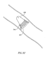
- Fig. 3D depicts a coil like mechanism 350 that may be bonded or otherwise connected to vessel blocking device 200.
- Coil like mechanism 350 may enclose at least a portion of cap 250 and/or base 260, according to some embodiments of the present invention.
- Coil like mechanism 350 may be expanded by for example balloons 240, cap 250 and/or base 260, optionally providing support to vessel blocking device 200.
- coil-like mechanism 350 may include one or more anchoring mechanisms 310 for anchoring vessel blocking device 200 into the walls of a vessel when stent-like mechanism 340 is expanded sufficiently.
- Stent-like mechanism 340 may be constructed from metal or other suitable materials.
- FIG. 4 depicts examples 4A-4E of anchoring mechanisms that lie on a substrate 400, according to some embodiments of the present invention.
- Fig 4A depicts straight spikes extending from substrate 400.
- Fig 4B depicts cross type spikes extending from substrate 400.
- Fig 4C depicts hook-like spikes extending outwards from substrate 400.
- Fig 4D depicts bent spikes at various angles extending from substrate 400, for example, enabling criss-cross anchoring.
- Fig 4E depicts a plurality of spikes that are "locked on" to each other, on substrate 400.
- Other anchoring mechanisms may be used, using spikes, hooks, pins or other suitable bonding elements.
- Anchoring mechanisms may be arranged in other suitable arrangements, or in any combination of arrangements.
- Anchoring mechanisms may be constructed from metal, plastic or any other suitable materials.
- FIG. 5A depicts a vessel blocking device 200, according to some embodiments of the present invention.
- Vessel blocking device 200 may include, for example, two balloons or pairs of balloons, for example, 560 and 570, at proximal side and distal side respectively of cap 250.
- gas and/or liquids may be released through catheter 210.
- the release of gas and/or liquids may result in a low or relatively low pressure area or a vacuum forming between balloons 560 and balloons 570.
- the pressure may be low relative to for example the surrounding tissue, or the blood pressure in the nearby sections of the vessel.
- the vacuum may cause the walls 555 of vessel 205 to be sucked inwards, for example, towards cap 250 and/or base 260, until, for example, anchoring mechanisms 310 anchor themselves into the walls 555 of vessel 205.
- the balloons may be deflated and catheter 210 may be extracted, together with other non required elements of vessel blocking device 200, leaving required elements of cap 250 and/or base 260 in vessel 205. Any number or type of balloons may be used, in any combination.
- Fig. 5B depicts a vessel blocking device 200 being anchored to walls 555 of vessel 205, using hook-type anchoring mechanisms 580.
- a low or relatively low pressure area or vacuum may be created in an area of vessel 205, therefore causing the vessel walls to be forced inwards until engaging with hooks 580.
- cap 250 and/or base 260 have been anchored to walls 555 the balloons may be deflated and the catheter may be extracted, leaving the cap and/or base 260 in vessel 205. Any combination of the above steps may be implemented. Other steps or series of steps may be used.
- a plurality of balloons may be used to generate internal pressure that may cause a vessel to collapse, thereby permanently blocking the vessel.
- Each of a plurality of vessels may be individually controlled, or may be controlled in groups.
- balloons may be inflated and deflated to enable control over internal pressure of the vessel, anchoring and de-anchoring of vessel blocking device 200 to the vessel walls, or other suitable functions.
- vessel blocking device e.g., device 200 of Fig. 2 or other embodiments discussed herein
- vessel blocking device may be inserted into a vessel (e.g., 205 of Fig. 2 ) by an insertion device, for example from within a catheter (e.g., 210 in Fig. 2 ), with elements of vessel blocking device 200 being in a contracted or folded position.
- Other suitable devices may be used.
- blocking device 200 may be inserted into a junction of a vessel (e.g. 106 of Fig. 1 ) where a superficial or another vessel is to be blocked and/or treated.
- one or more balloons may be expanded, for example inflated, thereby expanding cap and/or base of blocking device (e.g., cap 250 and/or base 260 of blocking device 200 of Fig. 2 ) towards the vessel wall.
- inflation of, for example, at least one balloon may create a vacuum or low pressure area in an area of the vessel which may cause the vessel walls to be forced inwards until engaging with vessel blocking device anchoring mechanism (e.g., anchoring mechanism 310 of blocking device 200 of Fig.5A ).
- vessel blocking device anchoring mechanism e.g., anchoring mechanism 310 of blocking device 200 of Fig.5A
- cap 250 and/or base 260 may continue to be expanded until piercing, colliding, pressuring etc.
- vessel blocking device e.g., device 200 of Fig. 2
- catheter e.g., catheter 210 of Fig. 2
- unnecessary elements of vessel blocking device 200 and/or other elements from within vessel 205 may be removed together with catheter 210 from the patient, leaving required elements of vessel blocking device 200 in place in vessel 205. Any combination of the above steps may be implemented. Other steps or series of steps may be used.
- a vessel blocking device may be a collapsible or reversible device, for example, which is able to change its shape and to return to the former shape.
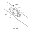
- Collapsible plug or blocking device 600 which may be constructed from stainless steel, Nitinol, biodegradable polypropylen, plastic material for use inside blood vessels, or any other suitable materials, may be delivered in a collapsed or folded state from within a delivery capsule, a catheter or alternative delivery device, for example, within a guide wire or guide balloon of a catheter etc.
- Plug 600 may be expandable into any suitable shape to fit within a vessel 605 (e.g., a varicose vein), and to be substantially lodged between walls of a vessel at a target location.
- a vessel 605 e.g., a varicose vein
- Plug 600 in its expanded form may have a ring shape, oval, figure-8 (e.g., Fig. 6B ) or another suitable shape.
- Plug 600 may include an interconnected or mesh type architecture that is known in the art of stenting. Other suitable architectures may be used.
- Plug 600 may include clasps, fasteners, hooks 610 or other suitable locking or catching elements to enable engaging, catching, fastening, dragging or otherwise locking plug 600 to walls of vessel 605.
- Hooks 610 may be configured to be directed in multiple directions to enable locking of plug 600 to walls of vessel 605 in multiple directions and locations.
- hooks may be configured like VelcroTM or other suitable fastening tape, consisting of, for example, a strip of nylon with a surface of minute hooks that fasten to a corresponding strip with a surface of uncut pile.
- hooks 610 may be directed to face left wall 620 and right wall 625 of vessel 605 (left and right being relative terms, and being used for the point of view shown), such that when pressure is applied externally to vessel 605, adjacent to plug 600, hooks 610 may engage both left wall 620 and right wall 625, and/or both ceiling and floor of the vessel, thereby fusing the vessel walls together, optionally around plug 600. Hooks may be configured in other directions, to enable sealing of plug 600 to vessel 605 at one or more locations.
- a target area of a vessel may be blocked by vessel blocking device which may include a plug 660 constructed from a memory material, for example, Nitinol or other suitable materials.
- Memory plug 660 may be delivered in a collapsed or folded state from within a delivery capsule, a catheter or alternative delivery device, for example, within a guide wire or guide balloon of a catheter etc.
- Memory plug 660 may be expanded after delivery to a selected area, such that the plug may engage the walls of vessel 675.
- Memory plug 660 may include hooks 670 or other suitable locking or catching elements to enable engaging, catching, or otherwise locking plug 660 to vessel walls 675.
- Hooks 670 may be configured to be directed in one or more directions to enable locking of plug 660 to walls of vessel 675.
- memory plug 660 may return to a predetermined shape, for example, a flat shape that enables the walls of the vessel to be blocked, fused or sealed around plug 660.
- hooks 670 may engage vessel walls 675 and may fuse and/or connect vessel walls together, around plug 660.
- a doctor or a health professional may press outside the body in proximity to the plug 660 location and may cause plug 660 to flatten and/or collapse.
- Plug 660 may be constructed from absorbable and/or dissolvable materials which may dissolve in the body after a certain period of time which may increase the encapsulation in the treatment area, for example, the saphenofemoral junction area, and may prevent recanalization.
- plug 600 in its collapsed, folded or pressured state may permanently fasten the walls of vein 605 together, optionally joining the walls by being fused to plug 600, thereby providing a sealed zone or area in which treatment may be applied.
- An outside pressure may be applied to plug 600 when it is placed in the preferred position in the vessel and may result in engagement and/or collapsing of the vessel walls towards plug 600, by for example, hooks or other anchoring mechanism. This may enable blocking or occluding of a vessel.
- Plug 600 may be naturally expandable, collapsible, may be a memory shape material, or may have other suitable shapes and/or designs to enable forming of a sealed zone in a vessel.
- a plug in collapsed, minimized or shrunken form may be delivered to a selected location using, for example, a delivery catheter, and optionally using ultrasonic scanning to determine the selected location.
- the plug may be expanded, for example, using a balloon or other suitable mechanisms.
- pressure may be applied externally to the vessel at the area which is in proximity to the selected location to allow engagement of the locking mechanisms to the vessel walls.
- hooks or other locking mechanisms may engage the vessel walls by fusing the vessel walls together, optionally around the plug.
- locking mechanisms may anchor and/or connect the blocking plug to the vessel wall and external pressure may change the shape of the plug and may create an obstruction of the vessel.
- the external pressure may be released.
- the plug may be permanently collapsed to provide a seal or a block at the selected location in the vessel.
- the vessel blockage may be verified, for example, using ultrasonic scanning or any other verifying technique.
- treatment may be applied to the treatment area, which may be defined by the positioning of the plug. Other steps and series of steps, may be used, and certain steps may be omitted.
- the vessel upstream of the blockage may be treated.
- device 200 of Fig. 2 and/or other suitable devices may be used to ligate the segment while significantly limiting the risk of embolic damage, and optionally while inflicting minimal trauma to the surrounding tissue.
- a sclerosing agent may be delivered to the segment distal to the ligation, using for example a drug catheter. The agent delivery may be done while suction of blood through catheter 210 to generate zero pressure. The zero pressure may prevent the sclerosing agent to penetrate other vessel.
- a sclerosing agent or other suitable agents may be dispersed at the distal tip 220 of device 200 or at other suitable locations. Other steps or series of steps may be used.
- Fig. 7A is a schematic illustration of a pressure control mechanism according to an embodiment of the present invention.
- a treatment area 720 may exist between the blocking device 760 and the distal tip of catheter 710. Delivery of a sclerosing or other suitable agent into a vessel may cause increased pressure within treatment area 720. Sclerosing or other suitable agent may be delivered into treatment area 720 through a small diameter catheter 730 or other suitable device which may be inserted through catheter 710 port 751 and may reach the distal end 755 of catheter 710. Increased pressure may, for example, enable the sclerosing agent to penetrate tributaries of the vein or other undesired locations, thereby entering the blood stream of the patient.
- suction device or port 750 which may be, for example, a syringe, suction pump, balloon device or other suitable devices which may be used to draw or pump out contents, for example blood, from around the distal end 755 of catheter 710, to reduce the pressure in treatment area 720.
- suction device 750 may be operated synchronously with the delivery of sclerosing agent through, for example, port 751 and inner catheter 730, to remove a similar quantity of contents as in being infused, thereby maintaining the pressure in treatment area 720.
- suction 750 may be used to maintain minimal, low, or zero pressure in treatment area 720, to reduce the entry of sclerosing agents into the blood stream, external to treatment area 720. Further, other steps or series of steps may be used.
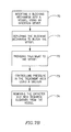
- a plug or blocking device in collapsed form may be delivered to a selected location using, for example, a delivery catheter. Ultrasonic scanning may be used to determine the selected location, and to monitor the delivery of the plug to the selected location.
- the plug or blocking device may be deployed, for example expanded, using a balloon or other suitable mechanisms, for example by radial forces restrained in the collapsed form, to block the selected vessel (as described in detail above).
- treatment may be applied to the treatment area, which may be defined by the positioning of the plug.
- sclerosing or other agents may be dispensed to close the selected vessel, for example, sclerosing agents may be inserted into the blocked area through a catheter.
- a suction device e.g., suction device 750 of Fig. 7A
- the suction may enable for example control of the pressure inside the treatment area.
- suction device e.g., suction device 750 of Fig.
- the catheter and the various components that are not intended to remain in the vessel may be pulled out of the vessel.
- the plug, together with the sclerosing agents may be left in the vessel, to destroy or close the unwanted vessel, and to seal off the vessel such that the sclerosing agent cannot flow though the vessel into the blood stream. Further, other steps or series of steps may be used.
- Fig. 7C is a schematic illustration of a pressure reducing device according to some embodiments of the present invention.
- Delivering of a sclerosing or other suitable agent into a vessel may cause increased pressure within a treatment area (e.g., treatment area 720 of Fig 7A ).
- Increased pressure may, for example, enable the sclerosing agent to penetrate tributaries of the vein or other undesired locations, thereby entering the blood stream of the patient.
- a pressure reducing device 770 which may include, for example, one or more expandable/collapsible balloons 775, may be used to push and/or pull out contents, for example blood, from vein/vessel 702, to reduce the pressure in treatment area 720.
- pressure reducing device 770 may be operated synchronously with the delivery of sclerosing agent, to remove a similar quantity of contents as in being infused, thereby maintaining the pressure in treatment area 720.
- pressure reducing device 770 may be used to maintain minimal, low, or zero pressure in treatment area 720, to reduce the entry of sclerosing agents into the blood stream, external to treatment area 720.
- FIG. 8 schematically illustrates a transverse view of an intraluminal vessel occluding stent or blocking device 800 according to an embodiment of the present invention.
- Occluding stent 800 may be inserted, for example, into a target vessel 805 that requires treatment, for example, a safenus vein, a bifurcated vessel or an occluded blood segment that is to be blocked and/or otherwise treated, or the saphenofemoral junction area 845 between a deep vein 843 and safenus vein 805. Other suitable areas may be treated.
- the target vessel 805 may be connected to another vessel, for example, as the safenus vein is connected to the deep vein by plurality of perfurant veins 842.
- Such insertion of occluding stent 800 may be implemented, for example, using an insertion device, for example, catheter 810, which may include a guidewire 830, to help guide occluding stent 800 to a selected location.
- Occluding stent 800 may be inserted into vessel 805 through catheter 810 in its compact, collapsed or minimized form or shape.
- catheter 810 pusher or additional catheter 835, which may be a thinner lumen catheter relative to catheter 810 and may be inserted inside catheter 810 lumen (not shown).
- additional catheter 835 which may be a thinner lumen catheter relative to catheter 810 and may be inserted inside catheter 810 lumen (not shown).
- Catheter 835 may include for example a drug dispensing mechanism 825, to enable delivery of a pharmaceutical compound, medication or agent, herein referred to as a sclerosing agent, to a target area.
- Catheter 810 may include a distal tip 820 which may be located in proximity to the blocking area.
- Vessel occluding stent or blocking device 800 may be expandable into an hourglass shape, or into the shape of two cones 805 and 806 or other concave, bowl or hemispherical shaped devices, typically connected or attached at their narrow ends to fit within vessel 805 (e.g., a varicose vein), and to substantially be lodged between walls of a vessel at a target location. Other shapes may be used.
- vessel occluding stent 800 in its expanded form may have the shape of two cones, where the upper cone may prevent blood from penetrating the treatment area 833 while the lower cone may prevent sclerosing agents from entering into the blood stream, external to treatment area 833.
- Upper and lower are relative terms when used herein; lower generally means in proximity to the insertion device insertion point.
- Vessel occluding stent 800 may include an interconnected or mesh type architecture that is known in the art of stenting. Other suitable architectures may be used.
- Vessel occluding stent 800 may be constructed from stainless steel, graft, film, Nitinol, biodegradable polypropylen, plastic material for use inside blood vessels, or other suitable materials.
- Vessel occluding stent 800 may be constructed from absorbable and/or dissolvable materials which may dissolve in the body after a certain period of time and may increase the encapsulation in the treatment area, for example, the saphenofemoral junction area 845, and may prevent recanalization. Vessel occluding stent 800 may be delivered in a collapsed state from within a delivery capsule or alternative delivery device, for example, within a guide wire or guide balloon of a catheter etc.
- Vessel occluding stent 800 may include clasps, fasteners, hooks 811 and/or 812 or other suitable locking or catching elements to enable engaging, catching, fastening, dragging or otherwise locking vessel occluding stent 800 to vessel walls 805.
- Hooks 811 and/or 812 may be configured to be directed in multiple directions to enable locking of vessel occluding stent 800 to walls of vessel 805 in multiple directions and locations.
- hooks may be configured like VelcroTM or other suitable fastening tape, consisting of, for example, a strip of nylon with a surface of minute hooks that fasten to a corresponding strip with a surface of uncut pile. Hooks may be configured in other directions, to enable sealing of vessel occluding stent 800 to vessel 805 at one or more locations. Other fastening or fixing methods may be used.
- Vessel occluding stent 800 may include floss or a wire 840, for example, a medical suture type which may be absorbable and may dissolve in the body after a limited period of time.
- the suture may be made of biocompatible material.
- Wire 840 may be coated with occluding agent, for example, fibrin, sclerosant or any other suitable occluding material.
- Wire 840 may be connected to the lower cone 806 of vessel occluding stent 800 or to any other point of vessel occluding stent 800 and may come out of port 816 of catheter 810 or may be released while pulling of catheter 810 pusher or catheter 835 out of catheter 810.
- Wire 840 may be used to guide and lead device 800 to a selected location. Wire 840 may be used to prevent migration or movement of vessel occluding stent 800 inside vessel 805 until hooking mechanism 811 and/or 812 is engaged with vessels walls 805. In addition wire 840 may be used in emergency situation for pulling the vessel occluding stent 800 out of vessel 805.
- a treatment area 833 may exist between the occluding stent 800 and the distal tip 820 of catheter 810.
- Delivering of a sclerosing or other suitable agent into a vessel while pulling out catheter 810 and/or catheter 835 may cause increased pressure within treatment area 833.
- Sclerosing or other suitable agent may be delivered into treatment area 833 through a catheter 835 or other suitable device which may be inserted through port 825 and may reach the distal end 820 of catheter 810 and treatment area 833.
- Increased pressure may, for example, enable the sclerosing agent to penetrate tributaries of the vein or other undesired locations, thereby entering the blood stream of the patient, for example, via perforant veins 842.
- Internal vein pressure may be controlled using a suction device to selectively remove contents from the vein.
- suction device or port 815 which may be, for example, a syringe, suction pump, balloon device or other suitable devices which may be used to draw or pump out contents, for example blood, from around the distal end 820 of catheter 810, to reduce the pressure in treatment area 833.
- suction device 815 may be operated synchronously with the delivery of sclerosing agent through, for example, port 815 and inner catheter 835, to remove a similar quantity of contents as in being infused, thereby maintaining the pressure in treatment area 833.
- controlling the pressure in the treatment area may include reduction in pressure in the treatment area, for example, suction 815 may be used to maintain minimal, low, or zero pressure in treatment area 833, to reduce the entry of sclerosing agents into the blood stream, external to treatment area 833. Further, other steps or series of steps may be used.
- a hole may be left by the extraction of catheter guidewire (e.g., guidewire 230 of Fig. 2 ).
- catheter guidewire e.g., guidewire 230 of Fig. 2
- Such a hole, gap or opening, etc. may be partially or completely blocked, for example, using a plug or other suitable blocking element to enable cap (e.g., cap 250 of Fig. 2 ) to seal vessel 205.
- intraluminal device configured for vessel ligation
- the intraluminal device may be configured for ligating other bifurcated lumen, artery or vessel, e.g. in the vascular, biliary, genitourinary, gastrointestinal, nervous and respiratory systems, which may have narrowed, weakened, distorted, or otherwise deformed structures. Other lumens may be blocked.
Applications Claiming Priority (4)
| Application Number | Priority Date | Filing Date | Title |
|---|---|---|---|
| US59239704P | 2004-08-02 | 2004-08-02 | |
| US62687404P | 2004-11-12 | 2004-11-12 | |
| EP05778828A EP1786503A4 (fr) | 2004-08-02 | 2005-08-01 | Dispositif et procede de traitement d'un vaisseau |
| PCT/US2005/027351 WO2006017470A2 (fr) | 2004-08-02 | 2005-08-01 | Dispositif et procede de traitement d'un vaisseau |
Related Parent Applications (1)
| Application Number | Title | Priority Date | Filing Date |
|---|---|---|---|
| EP05778828A Division EP1786503A4 (fr) | 2004-08-02 | 2005-08-01 | Dispositif et procede de traitement d'un vaisseau |
Publications (3)
| Publication Number | Publication Date |
|---|---|
| EP2708191A2 true EP2708191A2 (fr) | 2014-03-19 |
| EP2708191A3 EP2708191A3 (fr) | 2014-08-06 |
| EP2708191B1 EP2708191B1 (fr) | 2021-03-03 |
Family
ID=35839846
Family Applications (2)
| Application Number | Title | Priority Date | Filing Date |
|---|---|---|---|
| EP05778828A Withdrawn EP1786503A4 (fr) | 2004-08-02 | 2005-08-01 | Dispositif et procede de traitement d'un vaisseau |
| EP13196092.4A Active EP2708191B1 (fr) | 2004-08-02 | 2005-08-01 | Dispositif de traitement d'un vaisseau |
Family Applications Before (1)
| Application Number | Title | Priority Date | Filing Date |
|---|---|---|---|
| EP05778828A Withdrawn EP1786503A4 (fr) | 2004-08-02 | 2005-08-01 | Dispositif et procede de traitement d'un vaisseau |
Country Status (10)
| Country | Link |
|---|---|
| US (3) | US8545532B2 (fr) |
| EP (2) | EP1786503A4 (fr) |
| JP (1) | JP4956766B2 (fr) |
| KR (1) | KR101241254B1 (fr) |
| CN (1) | CN101850150B (fr) |
| AU (1) | AU2005271635B2 (fr) |
| CA (1) | CA2575812C (fr) |
| ES (1) | ES2873101T3 (fr) |
| IL (1) | IL181090A (fr) |
| WO (1) | WO2006017470A2 (fr) |
Families Citing this family (30)
| Publication number | Priority date | Publication date | Assignee | Title |
|---|---|---|---|---|
| WO2008124790A2 (fr) | 2002-07-10 | 2008-10-16 | Angiodynamics, Inc. | Dispositif et procédé pour le traitement endovasculaire pour provoquer la fermeture d'un vaisseau sanguin |
| AU2005271635B2 (en) | 2004-08-02 | 2012-04-05 | V.V.T. Med Ltd. | Device and method for treating a vessel |
| US20080243068A1 (en) * | 2005-12-29 | 2008-10-02 | Kamal Ramzipoor | Methods and apparatus for treatment of venous insufficiency |
| WO2009104189A2 (fr) * | 2008-02-20 | 2009-08-27 | V.V.T. Medical Ltd. | Procédé et dispositif d'administration veineuse de substance médicale liquide |
| EP2353521B1 (fr) | 2010-02-07 | 2016-07-06 | V.V.T. Medical Ltd. | Dispositifs intravasculaires pour le traitement de vaisseaux sanguins |
| US9247942B2 (en) | 2010-06-29 | 2016-02-02 | Artventive Medical Group, Inc. | Reversible tubal contraceptive device |
| WO2012002944A1 (fr) | 2010-06-29 | 2012-01-05 | Artventive Medical Group, Inc. | Réduction d'un écoulement à travers une structure tubulaire |
| US9149277B2 (en) | 2010-10-18 | 2015-10-06 | Artventive Medical Group, Inc. | Expandable device delivery |
| US20150142025A1 (en) * | 2012-06-26 | 2015-05-21 | V.V.T. Med Ltd. | Biodegradable blood vessel occlusion and narrowing |
| WO2014002087A1 (fr) * | 2012-06-26 | 2014-01-03 | V.V.T. Med Ltd. | Dispositifs d'occlusion de vaisseau, kits et procédés associés |
| US20140073907A1 (en) | 2012-09-12 | 2014-03-13 | Convergent Life Sciences, Inc. | System and method for image guided medical procedures |
| US9095344B2 (en) | 2013-02-05 | 2015-08-04 | Artventive Medical Group, Inc. | Methods and apparatuses for blood vessel occlusion |
| US8984733B2 (en) | 2013-02-05 | 2015-03-24 | Artventive Medical Group, Inc. | Bodily lumen occlusion |
| US10660645B2 (en) | 2013-03-15 | 2020-05-26 | Embo Medical Limited | Embolization systems |
| CN112690853A (zh) * | 2013-03-15 | 2021-04-23 | 恩波医疗有限公司 | 栓塞系统 |
| US10675039B2 (en) | 2013-03-15 | 2020-06-09 | Embo Medical Limited | Embolisation systems |
| US9636116B2 (en) | 2013-06-14 | 2017-05-02 | Artventive Medical Group, Inc. | Implantable luminal devices |
| US9737308B2 (en) | 2013-06-14 | 2017-08-22 | Artventive Medical Group, Inc. | Catheter-assisted tumor treatment |
| US9737306B2 (en) | 2013-06-14 | 2017-08-22 | Artventive Medical Group, Inc. | Implantable luminal devices |
| US10149968B2 (en) | 2013-06-14 | 2018-12-11 | Artventive Medical Group, Inc. | Catheter-assisted tumor treatment |
| US10010328B2 (en) | 2013-07-31 | 2018-07-03 | NeuVT Limited | Endovascular occlusion device with hemodynamically enhanced sealing and anchoring |
| EP3027124B1 (fr) | 2013-07-31 | 2022-01-12 | Embolic Acceleration, LLC | Dispositifs pour embolisation endovasculaire |
| US10363043B2 (en) | 2014-05-01 | 2019-07-30 | Artventive Medical Group, Inc. | Treatment of incompetent vessels |
| GB2527550B (en) | 2014-06-25 | 2016-09-21 | Cook Medical Technologies Llc | Implantable medical device with lumen constriction |
| AU2017230242A1 (en) * | 2016-03-09 | 2018-09-13 | Elbe Valley Medical Ltd. | Device and system for restricting fluid flow in physiological vessels |
| US10813644B2 (en) | 2016-04-01 | 2020-10-27 | Artventive Medical Group, Inc. | Occlusive implant and delivery system |
| US20170367710A1 (en) * | 2016-06-24 | 2017-12-28 | Cook Medical Technologies Llc | Double sided occlusive device |
| US11517374B2 (en) * | 2017-10-03 | 2022-12-06 | Research Development Foundation | Systems and methods for coronary occlusion treatment |
| CN111167000A (zh) * | 2019-12-31 | 2020-05-19 | 李雷 | 脉管封闭装置 |
| WO2023286638A1 (fr) * | 2021-07-16 | 2023-01-19 | 株式会社カネカ | Cathéter et procédé pour faire fonctionner un cathéter |
Family Cites Families (21)
| Publication number | Priority date | Publication date | Assignee | Title |
|---|---|---|---|---|
| US4723549A (en) * | 1986-09-18 | 1988-02-09 | Wholey Mark H | Method and apparatus for dilating blood vessels |
| DE4101935A1 (de) | 1991-01-21 | 1992-07-23 | Fischer Matthias | Intravasaler ventilkoerper |
| FR2688401B1 (fr) * | 1992-03-12 | 1998-02-27 | Thierry Richard | Endoprothese expansible pour organe tubulaire humain ou animal, et outil de mise en place. |
| EP0793457B2 (fr) * | 1994-04-06 | 2006-04-12 | WILLIAM COOK EUROPE ApS | Dispositif medical destine a etre implante dans le systeme vasculaire d'un patient |
| DE69529338T3 (de) * | 1994-07-08 | 2007-05-31 | Ev3 Inc., Plymouth | Intravaskuläre Filtereinrichtung |
| US5725552A (en) * | 1994-07-08 | 1998-03-10 | Aga Medical Corporation | Percutaneous catheter directed intravascular occlusion devices |
| CN1216929A (zh) | 1996-02-02 | 1999-05-19 | 血管转换公司 | 用于阻塞通过血管的流动的方法与装置 |
| US6958059B2 (en) * | 1996-05-20 | 2005-10-25 | Medtronic Ave, Inc. | Methods and apparatuses for drug delivery to an intravascular occlusion |
| US7073504B2 (en) * | 1996-12-18 | 2006-07-11 | Ams Research Corporation | Contraceptive system and method of use |
| US6071292A (en) * | 1997-06-28 | 2000-06-06 | Transvascular, Inc. | Transluminal methods and devices for closing, forming attachments to, and/or forming anastomotic junctions in, luminal anatomical structures |
| GB9716497D0 (en) * | 1997-08-05 | 1997-10-08 | Bridport Gundry Plc | Occlusion device |
| AU9126598A (en) | 1997-09-05 | 1999-03-29 | Neurovasx, Inc. | Vessel occlusion device |
| US5895410A (en) * | 1997-09-12 | 1999-04-20 | B. Braun Medical, Inc. | Introducer for an expandable vascular occlusion device |
| US6997189B2 (en) * | 1998-06-05 | 2006-02-14 | Broncus Technologies, Inc. | Method for lung volume reduction |
| US7128073B1 (en) * | 1998-11-06 | 2006-10-31 | Ev3 Endovascular, Inc. | Method and device for left atrial appendage occlusion |
| US7018401B1 (en) * | 1999-02-01 | 2006-03-28 | Board Of Regents, The University Of Texas System | Woven intravascular devices and methods for making the same and apparatus for delivery of the same |
| US7160312B2 (en) * | 1999-06-25 | 2007-01-09 | Usgi Medical, Inc. | Implantable artificial partition and methods of use |
| US6251122B1 (en) * | 1999-09-02 | 2001-06-26 | Scimed Life Systems, Inc. | Intravascular filter retrieval device and method |
| US6953476B1 (en) | 2000-03-27 | 2005-10-11 | Neovasc Medical Ltd. | Device and method for treating ischemic heart disease |
| US6645205B2 (en) * | 2001-08-15 | 2003-11-11 | Core Medical, Inc. | Apparatus and methods for reducing lung volume |
| AU2005271635B2 (en) | 2004-08-02 | 2012-04-05 | V.V.T. Med Ltd. | Device and method for treating a vessel |
-
2005
- 2005-08-01 AU AU2005271635A patent/AU2005271635B2/en active Active
- 2005-08-01 WO PCT/US2005/027351 patent/WO2006017470A2/fr active Application Filing
- 2005-08-01 KR KR1020077005149A patent/KR101241254B1/ko active IP Right Grant
- 2005-08-01 EP EP05778828A patent/EP1786503A4/fr not_active Withdrawn
- 2005-08-01 ES ES13196092T patent/ES2873101T3/es active Active
- 2005-08-01 CN CN2010101359507A patent/CN101850150B/zh active Active
- 2005-08-01 JP JP2007524899A patent/JP4956766B2/ja active Active
- 2005-08-01 CA CA2575812A patent/CA2575812C/fr active Active
- 2005-08-01 US US11/659,083 patent/US8545532B2/en active Active
- 2005-08-01 EP EP13196092.4A patent/EP2708191B1/fr active Active
-
2007
- 2007-01-31 IL IL181090A patent/IL181090A/en active IP Right Grant
-
2013
- 2013-09-30 US US14/040,834 patent/US9566070B2/en active Active
-
2017
- 2017-02-13 US US15/430,723 patent/US20170150969A1/en not_active Abandoned
Non-Patent Citations (1)
| Title |
|---|
| None |
Also Published As
| Publication number | Publication date |
|---|---|
| US9566070B2 (en) | 2017-02-14 |
| WO2006017470A3 (fr) | 2007-03-01 |
| CN101850150B (zh) | 2013-10-16 |
| IL181090A0 (en) | 2007-07-04 |
| EP1786503A4 (fr) | 2012-08-29 |
| EP1786503A2 (fr) | 2007-05-23 |
| ES2873101T3 (es) | 2021-11-03 |
| EP2708191B1 (fr) | 2021-03-03 |
| KR101241254B1 (ko) | 2013-03-14 |
| US20090216261A1 (en) | 2009-08-27 |
| CA2575812A1 (fr) | 2006-02-16 |
| IL181090A (en) | 2014-04-30 |
| WO2006017470A2 (fr) | 2006-02-16 |
| KR20070083537A (ko) | 2007-08-24 |
| US8545532B2 (en) | 2013-10-01 |
| CA2575812C (fr) | 2015-03-17 |
| EP2708191A3 (fr) | 2014-08-06 |
| AU2005271635B2 (en) | 2012-04-05 |
| JP4956766B2 (ja) | 2012-06-20 |
| US20140031851A1 (en) | 2014-01-30 |
| JP2008508079A (ja) | 2008-03-21 |
| US20170150969A1 (en) | 2017-06-01 |
| CN101850150A (zh) | 2010-10-06 |
| AU2005271635A1 (en) | 2006-02-16 |
Similar Documents
| Publication | Publication Date | Title |
|---|---|---|
| US9566070B2 (en) | Device and method for treating a vessel | |
| US20200281604A1 (en) | Systems for venous occlusion for the treatment of venous insufficiency | |
| US6726674B2 (en) | Methods for minimally invasive, localized delivery of sclerotherapeutic agents | |
| US20190099171A1 (en) | Enhanced ultrasound visualization of intravascular devices | |
| US20070135791A1 (en) | Method for Infusing the Interior of a Blood Vessel | |
| US20130226201A1 (en) | Method and apparatus for occluding a blood vessel | |
| CN101076366A (zh) | 处理脉管的装置和方法 | |
| US20080243102A1 (en) | Apparatus for segmental varicose sclerosis | |
| AU2015203861B2 (en) | Methods and devices for venous occlusion for the treatment of venous insufficiency |
Legal Events
| Date | Code | Title | Description |
|---|---|---|---|
| PUAI | Public reference made under article 153(3) epc to a published international application that has entered the european phase |
Free format text: ORIGINAL CODE: 0009012 |
|
| 17P | Request for examination filed |
Effective date: 20131206 |
|
| AC | Divisional application: reference to earlier application |
Ref document number: 1786503 Country of ref document: EP Kind code of ref document: P |
|
| AK | Designated contracting states |
Kind code of ref document: A2 Designated state(s): AT BE BG CH CY CZ DE DK EE ES FI FR GB GR HU IE IS IT LI LT LU LV MC NL PL PT RO SE SI SK TR |
|
| PUAL | Search report despatched |
Free format text: ORIGINAL CODE: 0009013 |
|
| AK | Designated contracting states |
Kind code of ref document: A3 Designated state(s): AT BE BG CH CY CZ DE DK EE ES FI FR GB GR HU IE IS IT LI LT LU LV MC NL PL PT RO SE SI SK TR |
|
| RIC1 | Information provided on ipc code assigned before grant |
Ipc: A61B 17/12 20060101AFI20140630BHEP |
|
| STAA | Information on the status of an ep patent application or granted ep patent |
Free format text: STATUS: EXAMINATION IS IN PROGRESS |
|
| 17Q | First examination report despatched |
Effective date: 20180112 |
|
| GRAP | Despatch of communication of intention to grant a patent |
Free format text: ORIGINAL CODE: EPIDOSNIGR1 |
|
| STAA | Information on the status of an ep patent application or granted ep patent |
Free format text: STATUS: GRANT OF PATENT IS INTENDED |
|
| INTG | Intention to grant announced |
Effective date: 20200924 |
|
| GRAS | Grant fee paid |
Free format text: ORIGINAL CODE: EPIDOSNIGR3 |
|
| STAA | Information on the status of an ep patent application or granted ep patent |
Free format text: STATUS: GRANT OF PATENT IS INTENDED |
|
| GRAA | (expected) grant |
Free format text: ORIGINAL CODE: 0009210 |
|
| STAA | Information on the status of an ep patent application or granted ep patent |
Free format text: STATUS: THE PATENT HAS BEEN GRANTED |
|
| AC | Divisional application: reference to earlier application |
Ref document number: 1786503 Country of ref document: EP Kind code of ref document: P |
|
| AK | Designated contracting states |
Kind code of ref document: B1 Designated state(s): AT BE BG CH CY CZ DE DK EE ES FI FR GB GR HU IE IS IT LI LT LU LV MC NL PL PT RO SE SI SK TR |
|
| REG | Reference to a national code |
Ref country code: GB Ref legal event code: FG4D |
|
| REG | Reference to a national code |
Ref country code: AT Ref legal event code: REF Ref document number: 1366348 Country of ref document: AT Kind code of ref document: T Effective date: 20210315 Ref country code: CH Ref legal event code: EP |
|
| REG | Reference to a national code |
Ref country code: DE Ref legal event code: R096 Ref document number: 602005057153 Country of ref document: DE |
|
| REG | Reference to a national code |
Ref country code: IE Ref legal event code: FG4D |
|
| REG | Reference to a national code |
Ref country code: LT Ref legal event code: MG9D |
|
| PG25 | Lapsed in a contracting state [announced via postgrant information from national office to epo] |
Ref country code: BG Free format text: LAPSE BECAUSE OF FAILURE TO SUBMIT A TRANSLATION OF THE DESCRIPTION OR TO PAY THE FEE WITHIN THE PRESCRIBED TIME-LIMIT Effective date: 20210603 Ref country code: LT Free format text: LAPSE BECAUSE OF FAILURE TO SUBMIT A TRANSLATION OF THE DESCRIPTION OR TO PAY THE FEE WITHIN THE PRESCRIBED TIME-LIMIT Effective date: 20210303 Ref country code: GR Free format text: LAPSE BECAUSE OF FAILURE TO SUBMIT A TRANSLATION OF THE DESCRIPTION OR TO PAY THE FEE WITHIN THE PRESCRIBED TIME-LIMIT Effective date: 20210604 Ref country code: FI Free format text: LAPSE BECAUSE OF FAILURE TO SUBMIT A TRANSLATION OF THE DESCRIPTION OR TO PAY THE FEE WITHIN THE PRESCRIBED TIME-LIMIT Effective date: 20210303 |
|
| REG | Reference to a national code |
Ref country code: NL Ref legal event code: MP Effective date: 20210303 |
|
| REG | Reference to a national code |
Ref country code: AT Ref legal event code: MK05 Ref document number: 1366348 Country of ref document: AT Kind code of ref document: T Effective date: 20210303 |
|
| PG25 | Lapsed in a contracting state [announced via postgrant information from national office to epo] |
Ref country code: LV Free format text: LAPSE BECAUSE OF FAILURE TO SUBMIT A TRANSLATION OF THE DESCRIPTION OR TO PAY THE FEE WITHIN THE PRESCRIBED TIME-LIMIT Effective date: 20210303 Ref country code: PL Free format text: LAPSE BECAUSE OF FAILURE TO SUBMIT A TRANSLATION OF THE DESCRIPTION OR TO PAY THE FEE WITHIN THE PRESCRIBED TIME-LIMIT Effective date: 20210303 Ref country code: SE Free format text: LAPSE BECAUSE OF FAILURE TO SUBMIT A TRANSLATION OF THE DESCRIPTION OR TO PAY THE FEE WITHIN THE PRESCRIBED TIME-LIMIT Effective date: 20210303 |
|
| PG25 | Lapsed in a contracting state [announced via postgrant information from national office to epo] |
Ref country code: NL Free format text: LAPSE BECAUSE OF FAILURE TO SUBMIT A TRANSLATION OF THE DESCRIPTION OR TO PAY THE FEE WITHIN THE PRESCRIBED TIME-LIMIT Effective date: 20210303 |
|
| PG25 | Lapsed in a contracting state [announced via postgrant information from national office to epo] |
Ref country code: EE Free format text: LAPSE BECAUSE OF FAILURE TO SUBMIT A TRANSLATION OF THE DESCRIPTION OR TO PAY THE FEE WITHIN THE PRESCRIBED TIME-LIMIT Effective date: 20210303 Ref country code: CZ Free format text: LAPSE BECAUSE OF FAILURE TO SUBMIT A TRANSLATION OF THE DESCRIPTION OR TO PAY THE FEE WITHIN THE PRESCRIBED TIME-LIMIT Effective date: 20210303 Ref country code: AT Free format text: LAPSE BECAUSE OF FAILURE TO SUBMIT A TRANSLATION OF THE DESCRIPTION OR TO PAY THE FEE WITHIN THE PRESCRIBED TIME-LIMIT Effective date: 20210303 |
|
| REG | Reference to a national code |
Ref country code: ES Ref legal event code: FG2A Ref document number: 2873101 Country of ref document: ES Kind code of ref document: T3 Effective date: 20211103 |
|
| PG25 | Lapsed in a contracting state [announced via postgrant information from national office to epo] |
Ref country code: SK Free format text: LAPSE BECAUSE OF FAILURE TO SUBMIT A TRANSLATION OF THE DESCRIPTION OR TO PAY THE FEE WITHIN THE PRESCRIBED TIME-LIMIT Effective date: 20210303 Ref country code: PT Free format text: LAPSE BECAUSE OF FAILURE TO SUBMIT A TRANSLATION OF THE DESCRIPTION OR TO PAY THE FEE WITHIN THE PRESCRIBED TIME-LIMIT Effective date: 20210705 Ref country code: RO Free format text: LAPSE BECAUSE OF FAILURE TO SUBMIT A TRANSLATION OF THE DESCRIPTION OR TO PAY THE FEE WITHIN THE PRESCRIBED TIME-LIMIT Effective date: 20210303 Ref country code: IS Free format text: LAPSE BECAUSE OF FAILURE TO SUBMIT A TRANSLATION OF THE DESCRIPTION OR TO PAY THE FEE WITHIN THE PRESCRIBED TIME-LIMIT Effective date: 20210703 |
|
| REG | Reference to a national code |
Ref country code: DE Ref legal event code: R097 Ref document number: 602005057153 Country of ref document: DE |
|
| PLBE | No opposition filed within time limit |
Free format text: ORIGINAL CODE: 0009261 |
|
| STAA | Information on the status of an ep patent application or granted ep patent |
Free format text: STATUS: NO OPPOSITION FILED WITHIN TIME LIMIT |
|
| PG25 | Lapsed in a contracting state [announced via postgrant information from national office to epo] |
Ref country code: DK Free format text: LAPSE BECAUSE OF FAILURE TO SUBMIT A TRANSLATION OF THE DESCRIPTION OR TO PAY THE FEE WITHIN THE PRESCRIBED TIME-LIMIT Effective date: 20210303 |
|
| 26N | No opposition filed |
Effective date: 20211206 |
|
| PG25 | Lapsed in a contracting state [announced via postgrant information from national office to epo] |
Ref country code: SI Free format text: LAPSE BECAUSE OF FAILURE TO SUBMIT A TRANSLATION OF THE DESCRIPTION OR TO PAY THE FEE WITHIN THE PRESCRIBED TIME-LIMIT Effective date: 20210303 |
|
| REG | Reference to a national code |
Ref country code: CH Ref legal event code: PL |
|
| PG25 | Lapsed in a contracting state [announced via postgrant information from national office to epo] |
Ref country code: MC Free format text: LAPSE BECAUSE OF FAILURE TO SUBMIT A TRANSLATION OF THE DESCRIPTION OR TO PAY THE FEE WITHIN THE PRESCRIBED TIME-LIMIT Effective date: 20210303 |
|
| REG | Reference to a national code |
Ref country code: BE Ref legal event code: MM Effective date: 20210831 |
|
| PG25 | Lapsed in a contracting state [announced via postgrant information from national office to epo] |
Ref country code: LI Free format text: LAPSE BECAUSE OF NON-PAYMENT OF DUE FEES Effective date: 20210831 Ref country code: CH Free format text: LAPSE BECAUSE OF NON-PAYMENT OF DUE FEES Effective date: 20210831 |
|
| PG25 | Lapsed in a contracting state [announced via postgrant information from national office to epo] |
Ref country code: IS Free format text: LAPSE BECAUSE OF FAILURE TO SUBMIT A TRANSLATION OF THE DESCRIPTION OR TO PAY THE FEE WITHIN THE PRESCRIBED TIME-LIMIT Effective date: 20210703 Ref country code: LU Free format text: LAPSE BECAUSE OF NON-PAYMENT OF DUE FEES Effective date: 20210801 |
|
| PG25 | Lapsed in a contracting state [announced via postgrant information from national office to epo] |
Ref country code: IE Free format text: LAPSE BECAUSE OF NON-PAYMENT OF DUE FEES Effective date: 20210801 Ref country code: BE Free format text: LAPSE BECAUSE OF NON-PAYMENT OF DUE FEES Effective date: 20210831 |
|
| PGFP | Annual fee paid to national office [announced via postgrant information from national office to epo] |
Ref country code: FR Payment date: 20230130 Year of fee payment: 18 Ref country code: ES Payment date: 20230125 Year of fee payment: 18 |
|
| PG25 | Lapsed in a contracting state [announced via postgrant information from national office to epo] |
Ref country code: HU Free format text: LAPSE BECAUSE OF FAILURE TO SUBMIT A TRANSLATION OF THE DESCRIPTION OR TO PAY THE FEE WITHIN THE PRESCRIBED TIME-LIMIT; INVALID AB INITIO Effective date: 20050801 Ref country code: CY Free format text: LAPSE BECAUSE OF FAILURE TO SUBMIT A TRANSLATION OF THE DESCRIPTION OR TO PAY THE FEE WITHIN THE PRESCRIBED TIME-LIMIT Effective date: 20210303 |
|
| PGFP | Annual fee paid to national office [announced via postgrant information from national office to epo] |
Ref country code: IT Payment date: 20230131 Year of fee payment: 18 |
|
| PGFP | Annual fee paid to national office [announced via postgrant information from national office to epo] |
Ref country code: ES Payment date: 20240131 Year of fee payment: 19 |
|
| PGFP | Annual fee paid to national office [announced via postgrant information from national office to epo] |
Ref country code: DE Payment date: 20240219 Year of fee payment: 19 Ref country code: GB Payment date: 20240130 Year of fee payment: 19 |