EP2708094B1 - Induction oven for curing coatings on containers - Google Patents
Induction oven for curing coatings on containers Download PDFInfo
- Publication number
- EP2708094B1 EP2708094B1 EP12719861.2A EP12719861A EP2708094B1 EP 2708094 B1 EP2708094 B1 EP 2708094B1 EP 12719861 A EP12719861 A EP 12719861A EP 2708094 B1 EP2708094 B1 EP 2708094B1
- Authority
- EP
- European Patent Office
- Prior art keywords
- tubular container
- magnetic field
- container
- transport device
- heating coil
- Prior art date
- Legal status (The legal status is an assumption and is not a legal conclusion. Google has not performed a legal analysis and makes no representation as to the accuracy of the status listed.)
- Not-in-force
Links
Images


Classifications
-
- H—ELECTRICITY
- H05—ELECTRIC TECHNIQUES NOT OTHERWISE PROVIDED FOR
- H05B—ELECTRIC HEATING; ELECTRIC LIGHT SOURCES NOT OTHERWISE PROVIDED FOR; CIRCUIT ARRANGEMENTS FOR ELECTRIC LIGHT SOURCES, IN GENERAL
- H05B6/00—Heating by electric, magnetic or electromagnetic fields
- H05B6/02—Induction heating
- H05B6/10—Induction heating apparatus, other than furnaces, for specific applications
- H05B6/101—Induction heating apparatus, other than furnaces, for specific applications for local heating of metal pieces
- H05B6/103—Induction heating apparatus, other than furnaces, for specific applications for local heating of metal pieces multiple metal pieces successively being moved close to the inductor
-
- B—PERFORMING OPERATIONS; TRANSPORTING
- B05—SPRAYING OR ATOMISING IN GENERAL; APPLYING FLUENT MATERIALS TO SURFACES, IN GENERAL
- B05D—PROCESSES FOR APPLYING FLUENT MATERIALS TO SURFACES, IN GENERAL
- B05D3/00—Pretreatment of surfaces to which liquids or other fluent materials are to be applied; After-treatment of applied coatings, e.g. intermediate treating of an applied coating preparatory to subsequent applications of liquids or other fluent materials
- B05D3/02—Pretreatment of surfaces to which liquids or other fluent materials are to be applied; After-treatment of applied coatings, e.g. intermediate treating of an applied coating preparatory to subsequent applications of liquids or other fluent materials by baking
- B05D3/0254—After-treatment
- B05D3/0281—After-treatment with induction heating
-
- B—PERFORMING OPERATIONS; TRANSPORTING
- B05—SPRAYING OR ATOMISING IN GENERAL; APPLYING FLUENT MATERIALS TO SURFACES, IN GENERAL
- B05D—PROCESSES FOR APPLYING FLUENT MATERIALS TO SURFACES, IN GENERAL
- B05D3/00—Pretreatment of surfaces to which liquids or other fluent materials are to be applied; After-treatment of applied coatings, e.g. intermediate treating of an applied coating preparatory to subsequent applications of liquids or other fluent materials
- B05D3/20—Pretreatment of surfaces to which liquids or other fluent materials are to be applied; After-treatment of applied coatings, e.g. intermediate treating of an applied coating preparatory to subsequent applications of liquids or other fluent materials by magnetic fields
- B05D3/207—Pretreatment of surfaces to which liquids or other fluent materials are to be applied; After-treatment of applied coatings, e.g. intermediate treating of an applied coating preparatory to subsequent applications of liquids or other fluent materials by magnetic fields post-treatment by magnetic fields
-
- H—ELECTRICITY
- H05—ELECTRIC TECHNIQUES NOT OTHERWISE PROVIDED FOR
- H05B—ELECTRIC HEATING; ELECTRIC LIGHT SOURCES NOT OTHERWISE PROVIDED FOR; CIRCUIT ARRANGEMENTS FOR ELECTRIC LIGHT SOURCES, IN GENERAL
- H05B6/00—Heating by electric, magnetic or electromagnetic fields
- H05B6/02—Induction heating
- H05B6/10—Induction heating apparatus, other than furnaces, for specific applications
- H05B6/105—Induction heating apparatus, other than furnaces, for specific applications using a susceptor
- H05B6/107—Induction heating apparatus, other than furnaces, for specific applications using a susceptor for continuous movement of material
-
- H—ELECTRICITY
- H05—ELECTRIC TECHNIQUES NOT OTHERWISE PROVIDED FOR
- H05B—ELECTRIC HEATING; ELECTRIC LIGHT SOURCES NOT OTHERWISE PROVIDED FOR; CIRCUIT ARRANGEMENTS FOR ELECTRIC LIGHT SOURCES, IN GENERAL
- H05B6/00—Heating by electric, magnetic or electromagnetic fields
- H05B6/02—Induction heating
- H05B6/36—Coil arrangements
- H05B6/40—Establishing desired heat distribution, e.g. to heat particular parts of workpieces
Definitions
- the invention relates generally to material application systems, for example but not limited to powder coating material application systems. More particularly, the invention relates to magnetic induction heaters for curing or partially curing applied coating material on interior surfaces of containers such as tubular containers and cans, for example.
- Material application systems are used to apply one or more coating materials in one or more layers to interior or exterior surfaces of an object or workpiece.
- General examples are powder coating systems, as well as other particulate material application systems such as may be used in the food processing and chemical industries.
- Some containers have liquid coatings applied to interior or exterior surfaces.
- the coating material After a coating material, either liquid or powder, has been applied to a container interior surface, the coating material must cure. Many coating materials especially powder are cured with heat.
- the heat curing process may involve several steps, but one known process of curing coating materials is to use an induction heater to heat the container thereby curing the coating material. In some cases, an induction heater is used to partially cure the coating material, and the coating material thereafter reaches complete cure in an ambient environment or through additional curing steps.
- DE102009056320 discloses a method for interior lacquering of a metal container in an automatic production line, comprising transporting the container along a feed web by a conveying system through a station for applying the lacquer on the container, and subjecting the metal container to induction heating in a first phase above a station for polymerization of the lacquer that is applied on the container.
- GB 905131 discloses a conveying device for use in an inductive heating system adapted to rotate workpieces as they are conveyed.
- the embodiments disclosed herein are directed to methods and apparatus for at least partially curing or curing coating materials that have been applied to surfaces of containers. While the descriptions herein relate specifically to interior surfaces, the inventions may find application for exterior surfaces. While the various embodiments are also presented in the context of coating materials applied to interior surfaces of tubular containers, such description is not intended to be limiting but rather to include any container having a generally cylindrical shape, whether of a regular or irregular shape, including cans. Furthermore, the exemplary embodiments illustrate a configuration of an induction heater, such is not intended to be limiting. Any general design of an induction heater may be used to carry out the inventions herein, including well known parts such as coils, controls, motors and so on.
- the inventions rather are directed to disclosed aspects of new ways to provide or use an induction heater for containers, for example having to do with how the containers are moved through the magnetic field produced by the coil and, optionally, the coil shape.
- the inventions will find applications for curing or partially curing liquid or particulate coatings.
- the containers may be open ended cylinders or may include a closed end, for example in the nature of a two or three piece container or mono-block container. We refer to the main cylindrical body as the sidewall of the container and the closure element being the end or end plate.
- the induction coil may be wound so as to take on a rectangular looking profile when viewed end on.
- the coil being rectangular does not require sharp corners for example or even tight radiuses at the corners necessarily. Rather, rectangular means that the coil is characterized by four sides in which opposing pairs of generally parallel sides lie transverse but not necessarily perpendicular the other pair of opposing parallel sides.
- a generally rectangular coil may be formed, for example, by wrapping a number of wires about a rectangular core (which also need not have sharp corners), along a length that defines the longitudinal axis of the coil.
- the wire coil may also take on the appearance of a parallelogram that is not a perfectly formed rectangle shape even when wound about a generally rectangular core.
- the exemplary embodiments use a rectangular coil in part because tubular containers tend to have a generally rectangular shape when viewed from the side profile of the container body, see Figs. 3 and 6 for example.
- many containers have irregular shapes or have rectangular profiles combined with tapers and can ends that have more complex geometries.
- the induction coil may be shaped as needed (along with a core) in the form of a non-circular coil that broadly approximates the container body profile.
- exemplary or representative values and ranges may be included to assist in understanding the present disclosure, however, such values and ranges are not to be construed in a limiting sense and are intended to be critical values or ranges only if so expressly stated. Descriptions of exemplary methods or processes are not limited to inclusion of all steps as being required in all cases, nor is the order that the steps are presented to be construed as required or necessary unless expressly so stated.
- the induction heater 10 is an apparatus that may be used to at least partially cure or completely cure a coating material that has been applied to surfaces of a tubular container or other generally cylindrical workpiece W ( Fig. 2 ).
- the coating material has been applied to an interior surface.
- the interior surfaces may be smooth or irregular in contour and the workpiece itself may be irregular in shape or a simple cylinder.
- the workpiece may be an open cylinder at both ends or have a closed end that will also need to be heat cured.
- the induction heater 10 may include several basic parts, including an induction coil (24, Fig. 2 ) disposed within a main housing 12.
- the outer main housing 12 preferably is made of magnetic material so as to contain the magnetic fields generated by the induction heating coil.
- Also within the housing 12 may be one or more ferromagnetic members (items 48, Fig. 6 ) that can be used to shape the magnetic field that is produced by the induction coil.
- a control panel 14 may be provided in a convenient manner such as a standalone console or part of the main unit. The control system via a panel 14 may be used to execute operation of the induction heater 10 including the application of current to the induction coil, control of the workpiece transport device and so on.
- control system and panel 14 and operator interface used with the apparatus 10 forms no particular part of the present disclosure and may be conventional in design as well known in the art or specifically developed for a particular curing operation, such as for controlling current, voltage and power of the induction heating system.
- An exemplary control system for an induction heater is described in US Patent No. 5,529,703 issued on June 25, 1996 but many other control systems and interfaces may be used as needed.
- the induction heater 10 also may include a transport device 16 which may be but need not be under the control of the control system 14.
- the transport device 16 is used to move the workpieces through the induction heater 10, specifically through the magnetic field produced by the induction coil within the housing 12.
- the transport device 16 includes a loading or inlet end 16a and an unloading or outlet end 16b.
- the outlet side of the apparatus 10 may include a hood 18 with an attached exhaust pipe 20 that is connected to a suction apparatus (not shown).
- the hood is used to extract fumes that may be produced during the curing or heating process, thus the housing 12 is also intended to be tightly enclosed to contain fumes.
- the extraction hood 18 may also be integrated with the main housing 12 if so desired.
- the exemplary embodiments illustrated herein are for an air cooled induction coil, and the cooling equipment such as blowers (not shown) may be disposed in a lower utility bay 22 along with other control equipment as needed.
- the induction heater 10 may be equipped for water cooling as is known in the art.
- an induction coil 24 within the housing 12 resides an induction coil 24.
- the coil 24 is wrapped about a non-magnetic core 26, for example, a box shaped generally rectangular piece of fiberglass.
- the coil will typically be wrapped with a pitch P between each loop so that each turn of the coil has more of a parallelogram profile, and the coil may take on a helix shape albeit with straight parallel side portions.
- the number of turns, the amount of pitch and the associated pitch angle ⁇ of the coil will depend on the nature of the magnetic field needed for heating. These factors will vary depending on the type of container being heated, the material of the container, the properties of the coating material, the type of wire used in the coil, the power levels used and so on.
- each coil is typically made up of a plurality of wires bound together by a shroud or other suitable binding or sheath.
- the coil 24 is also typically affixed to the core 26 by a suitable material such as epoxy for example.
- the coil 24 has a profile such that there are generally parallel side portions 28a and 28b for each coil loop and generally parallel top and bottom portions 30a and 30b.
- the magnetic field 32 has a desirable characteristic that as the workpieces pass through the magnetic field, magnetically induced eddy currents 34 will be generated within the workpiece body in accordance with the right hand rule. These currents 34 will heat the workpiece, especially at the twelve o'clock and six o'clock portions, 36 and 38 respectively ( Fig.
- the magnetic field side portions 32a and 32b are useful for heating the container end E when present.
- the represented flux lines are a visual construct, or course, but aid in understanding how the workpieces are heated with the exemplary embodiments. Note the representation in Fig. 4 that the radiated magnetic field 32 is contained in the magnetic walls of the housing 12 and down through the core 26.
- the induction coil 24 has an alternating current applied thereto by a power source 44.
- a power source 44 may be controlled using the associated control system via the control panel 14.
- the representation in Fig. 4 is highly simplified, wherein the control system will monitor current, voltage and temperature of the workpiece and adjust the applied current/voltage accordingly, as is well known in the art. Alternatively these adjustments may be made manually as is known in the art.
- the applied alternating current results in an alternating magnetic field 32 that provides excellent induction of currents in the workpieces.
- the applied frequency and power may be chosen based on a number of factors, one of which is the workpiece material.
- Frequency ranges may also be selected to optimize heating, wherein a medium frequency induction heater may have a frequency in the range of 5kHz-15kHz, whereas a higher frequency induction heater may use 100kHz-1Megahertz.
- the medium frequency induction heater typically can be air cooled while the higher frequency induction heater may require water cooling.
- the power level may be set for a fixed or known load, resulting in a predictable and repeatable output and heating performance.
- the coil 24 may be made of any suitable material as is well known.
- magnet wire made of copper such as is commonly used for motor coils may be used.
- Litz wire which is more efficient in reducing heating of the coil.
- water cooled tubing may be used when operating at higher power and higher frequencies.
- the transport device 16 is schematically represented in Figs. 2 and 3 as a simple conveyor belt. As represented by the arrow 40, the transport device 16 moves the workpieces W through the coil 24 and its associated magnetic field 32 along a heating path or direction of travel 40 that is parallel with the direction of the magnetic force field 32 produced by the coil 24.
- the direction of the magnetic field 32 is represented generally by the arrow 42 in Fig. 3 .
- each container or workpieces W as noted above are generally cylindrical in profile although they may have irregularly shaped portions such as reduced necks N.
- each container will have a longitudinal axis X, which typically will also be an axis of symmetry.
- X we only label X on some of the illustrated containers for simplicity.
- the transport device 16 moves the workpieces through the magnetic field 32 and the coil 24 such that the direction of travel or heating path 40 is transverse, and in this embodiment generally perpendicular, to the longitudinal axis X of the workpiece.
- the transport device 16 moves the workpieces sideways through the magnetic field 32 in a direction of travel 40 that is generally perpendicular to the longitudinal axis X of the workpiece but generally parallel the direction 42 of the magnetic field 32.
- We refer to generally perpendicular because depending on the way that the coil 24 is wrapped about the core 26, the magnetic field may be in a direction that is not precisely parallel with the transport device direction of travel 40.
- the heating effect can be concentrated at the six and twelve o'clock positions.
- the sideways movement also allows the induction heater 10 to be used to heat a container end E.
- the transport device 16 also causes the container to rotate about its longitudinal axis, or in other words roll on its sidewall as it moves through the induction coil 24, as represented by the arrow 64.
- a generally rectangular coil profile is preferred, such is not required.
- the rectangular profile we have discovered works well for generally cylindrical containers, with or without irregular shaped portions, and is more efficient than, for example, a cylindrical coil; especially when the container is rotated about its longitudinal axis as it moves through the magnetic field in a direction of travel that is generally parallel the magnetic field and transverse the container longitudinal axis.
- coil profiles even cylindrical, may alternatively be used to carryout localized heating of the container sidewall and end when the container is rolled through the magnetic field along a direction of travel or heating path that is generally parallel to the magnetic field but transverse and preferably generally perpendicular to the longitudinal axis of the container (i.e. the axis of rotation).
- the exemplary embodiments show heating at the six and twelve o'clock positions, such is not necessarily required and the magnetic field may be shaped or presented to the workpieces in such a way to heat different portions of the workpiece body.
- the coil may be shaped so as to produce the proper orientation of the magnetic field that will be presented to those irregularly shaped portions.
- ferromagnetic members may also be used to further shape the magnetic field not only to accommodate irregular shaped portions but also for heating a container end, and also improving efficiency by concentrating the magnetic field at desired locations.
- the induction coil 24 resides within the housing 12.
- An induction tube 46 is provided within the induction coil and core assembly 24, 26.
- the induction tube 46 is made of non-magnetic materials such as fiberglass construction for example.
- the induction tube 46 serves as a support frame for one or more ferromagnetic members 48.
- the induction tube 46 also supports part of the transport device 16 which includes a stationary friction surface 50 and a conveyor system 52.
- the conveyor system 52 provides an arrangement for moving the workpieces W through the apparatus 10, and more specifically through the magnetic field 32 of the induction coil 24. Due to the magnetic fields present inside the induction heater 10, the transport device 16 is made entirely of non-magnetic parts.
- the conveyor system 52 includes a link chain 54, such as for example made of non-magnetic stainless steel, on which are mounted and spaced apart from each other a series of L-shaped pusher lugs 56.
- Each pusher lug 56 is mounted by its short leg 56a on a link 58 of the chain 54 using a pair of support arms 60 each attached on either side of the link 58.
- Bolts 62 may be used to secure the pusher lug 56 to the link 58.
- the conveyor chain 54 is disposed below the level of the friction surface 50. This assures that the workpieces actually rest on the stationary friction surface 50.
- Each workpiece W nests between two adjacent pusher lugs 56 and on top of the friction surface 50.
- the pusher lugs 56 contact the workpiece W and push the cans forward along the heating path 40 through the induction coil 24. Because the workpieces rest on the friction surface 50, the workpieces will roll on their sides by rotation about their longitudinal axis X as represented by the arrow 64.
- a conventional sprocket assembly 66 that is driven by a motor 68 may be used to control the speed of the conveyor chain 54, under the control of the control system used for the apparatus 10.
- a tension arm and sprocket 68 may be provided as needed to properly maintain tension on the chain 54 for accurate speed control.
- a first inner side plate 72 and a second inner side plate 74 extend along either side of the transport device 16 through the length of the induction tube 46 and also beyond to the unloading end 16b ( Fig. 1 ). These inner side plates also extend back to the inlet or loading end of the transport device 16a ( Fig. 1 ). At the loading side 16a these side plates may funnel somewhat towards the inlet to the induction tube 46 to help gently align containers that have perhaps been loaded somewhat askew onto the conveyor system 52.
- the inner side plates 72, 74 run parallel to each other, with the separation between the first and second inner side plates 72, 74 being chosen so as to closely contain but not contact the ends W1 and W2 of the workpiece W within the induction tube 46. It is desirable to have the ends W1, W2 close to the respective side plates to be in close proximity to the ferromagnetic members 48, but with enough of a gap that the workpieces do not rub up against side plates.
- the parallel friction surfaces 50 on either side of the conveyor assembly 52 along with the pusher lugs help maintain this narrow spacing while the containers roll along through the induction tube 46.
- first and second outer side plates 76, 78 Spaced apart from the inner side plates 72, 74 and coextending parallel therewith through the induction tube 46 are first and second outer side plates 76, 78. All four side plates 72, 74, 76 and 78 are made of non-magnetic material, such as fiberglass, high temperature polymers and plastics, for example Teflon and Nylon, and so on.
- the ferromagnetic members 48 positioned along the workpiece ends in the slots 80 are selected in terms of number and location so as to shape the magnetic field 32 to optimize heating of the ends W1 and W2.
- ferromagnetic members 48-1 may be disposed on the inside top wall 46a of the induction tube 46, using a bracket 82 that is attached to the inside wall such as with bolts 84. These members 48-1 may be spaced along the top of the induction tube 46 as needed to shape the magnetic field to optimize heating the workpiece sidewall W3.
- These members 48-1 may also be used for shaping the magnetic field to accommodate irregular shapes of the container side wall, such as tapers, necks and so on as exemplified in Fig. 6 .
- the ferromagnetic members 48 have a length that is into the sheet of the drawing and may be generally rectangular in shape. Other locations and numbers of ferromagnetic members 48 may be used as needed to achieve a desired magnetic field shape 32.
- the members 48 may in practice be assemblies of the actual ferromagnetic element and a side cushion such as made of silicon. As shown in Fig. 6A , the ferromagnetic members 48 may be assemblies of a ferromagnetic element 86 with two side cushions 88 on either planar side that cushion the ferromagnetic element 86 when the member 48 are inserted into the slot 80. The cushions 88 may be attached to the ferromagnetic elements 86 by any suitable means such as, for example, high temperature adhesives, for example, silicon based.
- the ferromagnetic members 48 may be positioned along the slot 80 anywhere along the length of the induction tube 46 and can easily be re-positioned as needed.
- the side rail assemblies 72/76 and 74/78 may be removable as with mounting bolts 90.
- Optional additional support side plates 92 may be provided at a greater width so as to allow longer containers to pass through the induction heater. The construction of such side plates may be as already described herein above.
- the optional additional support plates 92 may be disposed on an outside wall 94 of the induction tube 46 because the induction tube 46 is non-magnetic. This would represent the maximum container length that could be accommodated for given size induction tube 46.
- the inside support rails 72,76 and 74,78 could be re-positioned within the induction tube 46 by providing additional optional mounting sites.
- the ferromagnetic members increase overall design flexibility in accommodating differently shaped and sized containers without having to modify the coil. For the same reason, more than one coil may also increase such design flexibility. Moreover, the ferromagnetic members 48 not only may be used to concentrate the magnetic flux in desired locations, but may also be positioned so as to direct magnetic flux away from certain container regions as needed.
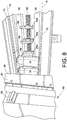
- Fig. 8 With reference to Fig. 8 we illustrate an another optional feature. Near the entrance to the induction tube 46 we suspend a hinged guard plate 94. In its natural position the plate 94 may hang vertically with a lower edge 96 positioned in close proximity to the upper surfaces of the workpieces. If a workpiece is not fully nested as shown in Fig. 8 , but rather vertically tilted, it will hit the plate 94. This will cause the workpiece to either drop fully down into the nested position between the adjacent pusher lugs 56, or will pivot the plate 94 towards the entrance to the induction tube 46, causing the plate 94 to actuate a proximity sensor 98 or other device for detecting misalignment of the workpiece.
- FIG. 8 illustrates the funneled entrance (emphasized with lines A) to the induction tube 46 provided by the side plates 72, 74 for helping align the containers properly as discussed above.
- the guard plate 94 may also serve as a safety feature in that if an operator or other person places a hand into the conveyor area too near the induction tube 46 inlet, the hand will pivot the plate and shut off the conveyor. This is useful as a safety device in situations where the apparatus 10 has been operated and there may be hot components near the entrance to the induction tube 46.
Description
- The invention relates generally to material application systems, for example but not limited to powder coating material application systems. More particularly, the invention relates to magnetic induction heaters for curing or partially curing applied coating material on interior surfaces of containers such as tubular containers and cans, for example.
- Material application systems are used to apply one or more coating materials in one or more layers to interior or exterior surfaces of an object or workpiece. General examples are powder coating systems, as well as other particulate material application systems such as may be used in the food processing and chemical industries. Some containers have liquid coatings applied to interior or exterior surfaces. These are but a few examples of a wide and numerous variety of systems used to apply coating materials to an object and to which the present inventions will find use.
- After a coating material, either liquid or powder, has been applied to a container interior surface, the coating material must cure. Many coating materials especially powder are cured with heat. The heat curing process may involve several steps, but one known process of curing coating materials is to use an induction heater to heat the container thereby curing the coating material. In some cases, an induction heater is used to partially cure the coating material, and the coating material thereafter reaches complete cure in an ambient environment or through additional curing steps.
-
DE102009056320 discloses a method for interior lacquering of a metal container in an automatic production line, comprising transporting the container along a feed web by a conveying system through a station for applying the lacquer on the container, and subjecting the metal container to induction heating in a first phase above a station for polymerization of the lacquer that is applied on the container. -
GB 905131 - The invention is defined by the claims.
- These and other aspects and advantages of the present invention will be apparent to those skilled in the art from the following description of the preferred embodiments in view of the accompanying drawings.
-
-
Fig. 1 illustrates an embodiment of an induction heating apparatus in accordance with the present inventions; -
Fig. 2 is a schematic representation of an induction heating apparatus showing workpieces traveling through an induction coil; -
Fig. 3 is an enlarged illustration of the entrance end of the induction apparatus ofFig. 2 ; -
Fig. 4 is the apparatus ofFig. 2 showing side portions of a magnetic field produced by an induction coil; -
Fig. 5 is a schematic representation of a workpiece passing through a flux field produced by the induction coil; -
Fig. 6 is a simplified schematic entrance side end view of an induction tube and related parts for an induction heater and transport device; -
Fig. 6A illustrates a side elevation and plan view of a ferromagnetic assembly that may be used in an induction heater; -
Fig. 7 is a partial schematic illustration of a transport device used to move containers through an induction tube; and -
Fig. 8 illustrates an optional guard plate to assist in aligning containers as they enter an induction oven as well as a safety feature. - The embodiments disclosed herein are directed to methods and apparatus for at least partially curing or curing coating materials that have been applied to surfaces of containers. While the descriptions herein relate specifically to interior surfaces, the inventions may find application for exterior surfaces. While the various embodiments are also presented in the context of coating materials applied to interior surfaces of tubular containers, such description is not intended to be limiting but rather to include any container having a generally cylindrical shape, whether of a regular or irregular shape, including cans. Furthermore, the exemplary embodiments illustrate a configuration of an induction heater, such is not intended to be limiting. Any general design of an induction heater may be used to carry out the inventions herein, including well known parts such as coils, controls, motors and so on. The inventions rather are directed to disclosed aspects of new ways to provide or use an induction heater for containers, for example having to do with how the containers are moved through the magnetic field produced by the coil and, optionally, the coil shape. The inventions will find applications for curing or partially curing liquid or particulate coatings. The containers may be open ended cylinders or may include a closed end, for example in the nature of a two or three piece container or mono-block container. We refer to the main cylindrical body as the sidewall of the container and the closure element being the end or end plate.
- We use the term "generally rectangular" in a broad sense to mean that the induction coil may be wound so as to take on a rectangular looking profile when viewed end on. The coil being rectangular does not require sharp corners for example or even tight radiuses at the corners necessarily. Rather, rectangular means that the coil is characterized by four sides in which opposing pairs of generally parallel sides lie transverse but not necessarily perpendicular the other pair of opposing parallel sides. A generally rectangular coil may be formed, for example, by wrapping a number of wires about a rectangular core (which also need not have sharp corners), along a length that defines the longitudinal axis of the coil. Thus, depending on the wire size and pitch of the wrapped wires, the wire coil may also take on the appearance of a parallelogram that is not a perfectly formed rectangle shape even when wound about a generally rectangular core.
- The exemplary embodiments use a rectangular coil in part because tubular containers tend to have a generally rectangular shape when viewed from the side profile of the container body, see
Figs. 3 and6 for example. However, many containers have irregular shapes or have rectangular profiles combined with tapers and can ends that have more complex geometries. But for the broader principles herein and concepts of the inventions disclosed herein, the induction coil may be shaped as needed (along with a core) in the form of a non-circular coil that broadly approximates the container body profile. - While various features may be described and illustrated herein as embodied in combination in the exemplary embodiments, these various features may be used in many alternative embodiments, either individually or in various combinations and subcombinations thereof. Still further, while various alternative embodiments as to the various features, such as alternative materials, structures, configurations, methods, circuits, devices and components, software, hardware, control logic, alternatives as to form, fit and function, and so on, may be described herein, such descriptions are not intended to be a complete or exhaustive list of available alternative embodiments, whether presently known or later developed. Additionally, even though some features may be described herein as being a preferred arrangement or method, such description is not intended to suggest that such feature is required or necessary unless expressly so stated. Still further, exemplary or representative values and ranges may be included to assist in understanding the present disclosure, however, such values and ranges are not to be construed in a limiting sense and are intended to be critical values or ranges only if so expressly stated. Descriptions of exemplary methods or processes are not limited to inclusion of all steps as being required in all cases, nor is the order that the steps are presented to be construed as required or necessary unless expressly so stated.
- With reference to
Fig. 1 , we illustrate an embodiment of an induction heater oroven 10. Herein we will use the terms induction heater and induction oven interchangeably. Theinduction heater 10 is an apparatus that may be used to at least partially cure or completely cure a coating material that has been applied to surfaces of a tubular container or other generally cylindrical workpiece W (Fig. 2 ). In the exemplary embodiments the coating material has been applied to an interior surface. The interior surfaces may be smooth or irregular in contour and the workpiece itself may be irregular in shape or a simple cylinder. The workpiece may be an open cylinder at both ends or have a closed end that will also need to be heat cured. - The
induction heater 10 may include several basic parts, including an induction coil (24,Fig. 2 ) disposed within amain housing 12. The outermain housing 12 preferably is made of magnetic material so as to contain the magnetic fields generated by the induction heating coil. Also within thehousing 12 may be one or more ferromagnetic members (items 48,Fig. 6 ) that can be used to shape the magnetic field that is produced by the induction coil. Acontrol panel 14 may be provided in a convenient manner such as a standalone console or part of the main unit. The control system via apanel 14 may be used to execute operation of theinduction heater 10 including the application of current to the induction coil, control of the workpiece transport device and so on. The particular control system andpanel 14 and operator interface used with theapparatus 10 forms no particular part of the present disclosure and may be conventional in design as well known in the art or specifically developed for a particular curing operation, such as for controlling current, voltage and power of the induction heating system. An exemplary control system for an induction heater is described inUS Patent No. 5,529,703 issued on June 25, 1996 but many other control systems and interfaces may be used as needed. - The
induction heater 10 also may include atransport device 16 which may be but need not be under the control of thecontrol system 14. Thetransport device 16 is used to move the workpieces through theinduction heater 10, specifically through the magnetic field produced by the induction coil within thehousing 12. Thetransport device 16 includes a loading orinlet end 16a and an unloading oroutlet end 16b. The outlet side of theapparatus 10 may include ahood 18 with an attachedexhaust pipe 20 that is connected to a suction apparatus (not shown). The hood is used to extract fumes that may be produced during the curing or heating process, thus thehousing 12 is also intended to be tightly enclosed to contain fumes. Theextraction hood 18 may also be integrated with themain housing 12 if so desired. - The exemplary embodiments illustrated herein are for an air cooled induction coil, and the cooling equipment such as blowers (not shown) may be disposed in a
lower utility bay 22 along with other control equipment as needed. Alternatively, theinduction heater 10 may be equipped for water cooling as is known in the art. - With reference to
Figs. 2 and3 , within thehousing 12 resides aninduction coil 24. Thecoil 24 is wrapped about anon-magnetic core 26, for example, a box shaped generally rectangular piece of fiberglass. Although thecoil 24 is wrapped about a rectangular core, the coil will typically be wrapped with a pitch P between each loop so that each turn of the coil has more of a parallelogram profile, and the coil may take on a helix shape albeit with straight parallel side portions. The number of turns, the amount of pitch and the associated pitch angle α of the coil will depend on the nature of the magnetic field needed for heating. These factors will vary depending on the type of container being heated, the material of the container, the properties of the coating material, the type of wire used in the coil, the power levels used and so on. In some applications more than onecoil 24 may be wrapped about thecore 26. Each coil is typically made up of a plurality of wires bound together by a shroud or other suitable binding or sheath. Thecoil 24 is also typically affixed to the core 26 by a suitable material such as epoxy for example. - With additional reference to
Figs. 3 and4 , as just noted thecoil 24 has a profile such that there are generallyparallel side portions bottom portions magnetic field 32 shape having generallyparallel side portions Fig. 4 ) and generally parallel upper andlower portions Fig. 5 ). Themagnetic field 32 has a desirable characteristic that as the workpieces pass through the magnetic field, magnetically inducededdy currents 34 will be generated within the workpiece body in accordance with the right hand rule. Thesecurrents 34 will heat the workpiece, especially at the twelve o'clock and six o'clock portions, 36 and 38 respectively (Fig. 5 ) relative to the surface area where the workpiece body transversely and preferably perpendicularly passes through themagnetic field 32, much like when a conductive wire passes through a magnetic field. The workpieces will of course experience heating in other portions of the container body but pronounced heating will occur at the twelve and six o'clock positions. The magneticfield side portions Fig. 4 ) are useful for heating the container end E when present. The represented flux lines are a visual construct, or course, but aid in understanding how the workpieces are heated with the exemplary embodiments. Note the representation inFig. 4 that the radiatedmagnetic field 32 is contained in the magnetic walls of thehousing 12 and down through thecore 26. - As represented schematically in
Fig. 4 , theinduction coil 24 has an alternating current applied thereto by apower source 44. Alternatively, pulsed currents may be used as is well known in the art. Thepower source 44 may be controlled using the associated control system via thecontrol panel 14. The representation inFig. 4 is highly simplified, wherein the control system will monitor current, voltage and temperature of the workpiece and adjust the applied current/voltage accordingly, as is well known in the art. Alternatively these adjustments may be made manually as is known in the art. The applied alternating current results in an alternatingmagnetic field 32 that provides excellent induction of currents in the workpieces. The applied frequency and power may be chosen based on a number of factors, one of which is the workpiece material. For poorly conductive workpieces like steel cans, lower power may be used, while for higher conductivity materials such as aluminum cans higher power may be needed. Frequency ranges may also be selected to optimize heating, wherein a medium frequency induction heater may have a frequency in the range of 5kHz-15kHz, whereas a higher frequency induction heater may use 100kHz-1Megahertz. The medium frequency induction heater typically can be air cooled while the higher frequency induction heater may require water cooling. In general, as is known, the power level may be set for a fixed or known load, resulting in a predictable and repeatable output and heating performance. - The
coil 24 may be made of any suitable material as is well known. For lower current systems, magnet wire made of copper such as is commonly used for motor coils may be used. For higher currents, it may be desirable to use Litz wire which is more efficient in reducing heating of the coil. When needed, water cooled tubing may be used when operating at higher power and higher frequencies. - The
transport device 16 is schematically represented inFigs. 2 and3 as a simple conveyor belt. As represented by thearrow 40, thetransport device 16 moves the workpieces W through thecoil 24 and its associatedmagnetic field 32 along a heating path or direction oftravel 40 that is parallel with the direction of themagnetic force field 32 produced by thecoil 24. The direction of themagnetic field 32 is represented generally by thearrow 42 inFig. 3 . - The containers or workpieces W as noted above are generally cylindrical in profile although they may have irregularly shaped portions such as reduced necks N. In any case, each container will have a longitudinal axis X, which typically will also be an axis of symmetry. We only label X on some of the illustrated containers for simplicity.
- In accordance with another inventive aspect then of this disclosure then and best illustrated in
Fig. 5 , thetransport device 16 moves the workpieces through themagnetic field 32 and thecoil 24 such that the direction of travel orheating path 40 is transverse, and in this embodiment generally perpendicular, to the longitudinal axis X of the workpiece. Thus, in the illustrated embodiments, thetransport device 16 moves the workpieces sideways through themagnetic field 32 in a direction oftravel 40 that is generally perpendicular to the longitudinal axis X of the workpiece but generally parallel thedirection 42 of themagnetic field 32. We refer to generally perpendicular because depending on the way that thecoil 24 is wrapped about thecore 26, the magnetic field may be in a direction that is not precisely parallel with the transport device direction oftravel 40. By having the containers move sideways through themagnetic field 32 produced from a generally rectangular coil, the heating effect can be concentrated at the six and twelve o'clock positions. The sideways movement also allows theinduction heater 10 to be used to heat a container end E. Also as further explained herein below, thetransport device 16 also causes the container to rotate about its longitudinal axis, or in other words roll on its sidewall as it moves through theinduction coil 24, as represented by thearrow 64. - It should be noted that although a generally rectangular coil profile is preferred, such is not required. The rectangular profile we have discovered works well for generally cylindrical containers, with or without irregular shaped portions, and is more efficient than, for example, a cylindrical coil; especially when the container is rotated about its longitudinal axis as it moves through the magnetic field in a direction of travel that is generally parallel the magnetic field and transverse the container longitudinal axis.. Particularly with the use of ferromagnetic field shaping elements described below, other coil profiles, even cylindrical, may alternatively be used to carryout localized heating of the container sidewall and end when the container is rolled through the magnetic field along a direction of travel or heating path that is generally parallel to the magnetic field but transverse and preferably generally perpendicular to the longitudinal axis of the container (i.e. the axis of rotation).
- Although the exemplary embodiments show heating at the six and twelve o'clock positions, such is not necessarily required and the magnetic field may be shaped or presented to the workpieces in such a way to heat different portions of the workpiece body.
- Because the container may have an irregular shape in portions, such as for example a reduced neck, the coil may be shaped so as to produce the proper orientation of the magnetic field that will be presented to those irregularly shaped portions. As discussed further below, ferromagnetic members may also be used to further shape the magnetic field not only to accommodate irregular shaped portions but also for heating a container end, and also improving efficiency by concentrating the magnetic field at desired locations.
- Having described the basic concepts and configuration for the inventions, we will now describe an exemplary detailed embodiment for the transport device and other optional features of the
induction heater 10. - With reference to
Figs. 6 and7 , theinduction coil 24 resides within thehousing 12. Aninduction tube 46 is provided within the induction coil andcore assembly induction tube 46 is made of non-magnetic materials such as fiberglass construction for example. Theinduction tube 46 serves as a support frame for one or moreferromagnetic members 48. Theinduction tube 46 also supports part of thetransport device 16 which includes astationary friction surface 50 and aconveyor system 52. - The
conveyor system 52 provides an arrangement for moving the workpieces W through theapparatus 10, and more specifically through themagnetic field 32 of theinduction coil 24. Due to the magnetic fields present inside theinduction heater 10, thetransport device 16 is made entirely of non-magnetic parts. - The
conveyor system 52 includes alink chain 54, such as for example made of non-magnetic stainless steel, on which are mounted and spaced apart from each other a series of L-shaped pusher lugs 56. Eachpusher lug 56 is mounted by itsshort leg 56a on alink 58 of thechain 54 using a pair ofsupport arms 60 each attached on either side of thelink 58.Bolts 62 may be used to secure thepusher lug 56 to thelink 58. - From
Fig. 7 it will be noted that theconveyor chain 54 is disposed below the level of thefriction surface 50. This assures that the workpieces actually rest on thestationary friction surface 50. Each workpiece W nests between two adjacent pusher lugs 56 and on top of thefriction surface 50. As theconveyor chain 54 moves, the pusher lugs 56 contact the workpiece W and push the cans forward along theheating path 40 through theinduction coil 24. Because the workpieces rest on thefriction surface 50, the workpieces will roll on their sides by rotation about their longitudinal axis X as represented by thearrow 64. We include the six and twelve o'clock legends onFig. 7 so that it will be readily understood that as the workpieces roll the entire workpiece body is exposed uniformly to the induced currents and resultant heating. The workpieces therefore are uniformly and efficiently heated even though at any given instant in time the heating is rather localized, for example in this embodiment at the six and twelve o'clock positions. Other techniques may be used to cause the workpieces to roll on their sides as they pass through themagnetic field 32 such that each workpiece is uniformly heated by the induced currents. - A
conventional sprocket assembly 66 that is driven by a motor 68 may be used to control the speed of theconveyor chain 54, under the control of the control system used for theapparatus 10. A tension arm and sprocket 68 may be provided as needed to properly maintain tension on thechain 54 for accurate speed control. - With reference to
Fig. 6 , a firstinner side plate 72 and a secondinner side plate 74 extend along either side of thetransport device 16 through the length of theinduction tube 46 and also beyond to the unloadingend 16b (Fig. 1 ). These inner side plates also extend back to the inlet or loading end of thetransport device 16a (Fig. 1 ). At theloading side 16a these side plates may funnel somewhat towards the inlet to theinduction tube 46 to help gently align containers that have perhaps been loaded somewhat askew onto theconveyor system 52. Within theinduction tube 46 however, theinner side plates inner side plates induction tube 46. It is desirable to have the ends W1, W2 close to the respective side plates to be in close proximity to theferromagnetic members 48, but with enough of a gap that the workpieces do not rub up against side plates. The parallel friction surfaces 50 on either side of theconveyor assembly 52 along with the pusher lugs help maintain this narrow spacing while the containers roll along through theinduction tube 46. - Spaced apart from the
inner side plates induction tube 46 are first and secondouter side plates side plates slot 80 is selected so as to closely receive and hold theferromagnetic members 48. - The
ferromagnetic members 48 positioned along the workpiece ends in theslots 80 are selected in terms of number and location so as to shape themagnetic field 32 to optimize heating of the ends W1 and W2. In addition, ferromagnetic members 48-1 may be disposed on the insidetop wall 46a of theinduction tube 46, using abracket 82 that is attached to the inside wall such as withbolts 84. These members 48-1 may be spaced along the top of theinduction tube 46 as needed to shape the magnetic field to optimize heating the workpiece sidewall W3. These members 48-1 may also be used for shaping the magnetic field to accommodate irregular shapes of the container side wall, such as tapers, necks and so on as exemplified inFig. 6 . - From the end view presented in
Fig. 6 , theferromagnetic members 48 have a length that is into the sheet of the drawing and may be generally rectangular in shape. Other locations and numbers offerromagnetic members 48 may be used as needed to achieve a desiredmagnetic field shape 32. - Because the ferromagnetic material tends to be quite brittle, the
members 48 may in practice be assemblies of the actual ferromagnetic element and a side cushion such as made of silicon. As shown inFig. 6A , theferromagnetic members 48 may be assemblies of aferromagnetic element 86 with twoside cushions 88 on either planar side that cushion theferromagnetic element 86 when themember 48 are inserted into theslot 80. Thecushions 88 may be attached to theferromagnetic elements 86 by any suitable means such as, for example, high temperature adhesives, for example, silicon based. For the ferromagnetic members 48-1 that are clamped to the upper wall of theinduction tube 46, in a similar manner cushions my be used on either side of the ferromagnetic element, or may be provided on theinside surface 46a of theinduction tube 46 and the inside surface of theclamp 82. - With the
slot 80 design, theferromagnetic members 48 may be positioned along theslot 80 anywhere along the length of theinduction tube 46 and can easily be re-positioned as needed. Also, theside rail assemblies 72/76 and 74/78 may be removable as with mountingbolts 90. Optional additionalsupport side plates 92 may be provided at a greater width so as to allow longer containers to pass through the induction heater. The construction of such side plates may be as already described herein above. In the example ofFig. 6 the optionaladditional support plates 92 may be disposed on anoutside wall 94 of theinduction tube 46 because theinduction tube 46 is non-magnetic. This would represent the maximum container length that could be accommodated for givensize induction tube 46. As another alternative, the inside support rails 72,76 and 74,78 could be re-positioned within theinduction tube 46 by providing additional optional mounting sites. - The ferromagnetic members increase overall design flexibility in accommodating differently shaped and sized containers without having to modify the coil. For the same reason, more than one coil may also increase such design flexibility. Moreover, the
ferromagnetic members 48 not only may be used to concentrate the magnetic flux in desired locations, but may also be positioned so as to direct magnetic flux away from certain container regions as needed. - With reference to
Fig. 8 we illustrate an another optional feature. Near the entrance to theinduction tube 46 we suspend a hingedguard plate 94. In its natural position theplate 94 may hang vertically with alower edge 96 positioned in close proximity to the upper surfaces of the workpieces. If a workpiece is not fully nested as shown inFig. 8 , but rather vertically tilted, it will hit theplate 94. This will cause the workpiece to either drop fully down into the nested position between the adjacent pusher lugs 56, or will pivot theplate 94 towards the entrance to theinduction tube 46, causing theplate 94 to actuate aproximity sensor 98 or other device for detecting misalignment of the workpiece. Other techniques may be used of course to detect containers that are not properly positioned before entering theinduction tube 46. Note thatFig. 8 illustrates the funneled entrance (emphasized with lines A) to theinduction tube 46 provided by theside plates - The
guard plate 94 may also serve as a safety feature in that if an operator or other person places a hand into the conveyor area too near theinduction tube 46 inlet, the hand will pivot the plate and shut off the conveyor. This is useful as a safety device in situations where theapparatus 10 has been operated and there may be hot components near the entrance to theinduction tube 46. - As an example, we have found that we can heat a tubular container to a range of about 230 °C (about 400 °F) with as short as 20 second heating times. These numbers vary of course depending on the nature of the coating material as well as the power of the induction heater and design, as well as the container shapes.
- There is thus provideed apparatus and processes that efficiently heat and at least partially cure coating material on tubular containers, including the capability to heat container ends as well as the container sidewall during the same heating operation as the containers pass through the induction coil. The container rotation allows for simpler coil designs, and evens out hot spots in the ends. It is noted that while rotation is not needed for heating the ends, rotation improves heating the sidewall by more uniformly causing the induction heating currents within the sidewall.
- The invention has been described with reference to the preferred embodiment. Modifications and alterations will occur to others upon a reading and understanding of this specification and drawings.
Claims (10)
- A method for inductive heating carried out on a tubular container of the type having a generally cylindrical body with a longitudinal axis, comprising the steps of generating an alternating magnetic field (32), and operating a transport device (16) to move a tubular container W along a heating path through the magnetic field (32) in a direction that is generally perpendicular to the longitudinal axis of the container body, wherein the transport device (16) continuously rotates the container body about the longitudinal axis of the container body while the container body moves through the magnetic field (32), wherein generating the alternating magnetic field (32) comprises using a magnetic induction heating coil (24) wound about a generally rectangular non-magnetic core (26) having top and bottom portions (30a, 30b) and first and second side portions (28a, 28b), the top, bottom, and first and second side portions of the heating coil (24) extending about the heating path (40), and wherein the transport device (16) moves the tubular container W along the heating path (40) through the magnetic field (32) and through the magnetic induction heating coil (24), characterized in that the method is for at least partially curing a coating material on the tubular container; in that the heating coil (24) is wound about a generally rectangular non-magnetic core (26), and in that the method further comprises the step of positioning one or more ferromagnetic members (48) along the heating path to shape the magnetic field (32).
- The method of claim 1 wherein the step of generating a magnetic field (32) comprises the step of passing an alternating current through a rectangular shaped coil (24).
- The method of claim 1 wherein the step of generating the magnetic field (32) comprises shaping the magnetic field (32) to heat the container body primarily at the 12 o'clock and 6 o'clock positions relative to the direction of movement of the container body.
- The method of claim 1 wherein the step of moving the tubular container W comprises the step of rolling the container body along the heating path through the magnetic field (32).
- The method of claim 1 wherein the transport device includes first and second parallel stationary friction surfaces (50) and wherein the step of operating the transport device includes causing the tubular container to roll along the first and second parallel stationary friction surfaces (50).
- Apparatus for inductive heating carried out on a tubular container of the type having a generally cylindrical body with a longitudinal axis, comprising a magnetic induction heating coil (24), a transport device (16) for moving a tubular container W along a heating path (40) in a direction that is generally perpendicular to the longitudinal axis of the container body, wherein the transport device (16) also rotates the tubular container W about the longitudinal axis of the tubular container while moving the tubular container along the heating path (40), wherein the magnetic induction heating coil (24) has a top portion (30a), a bottom portion (30b), and first and second side portions (28a, 28b), the top, bottom, and first and second side portions of the heating coil (24) extending about the heating path, the transport device (16) moving the tubular container along the heating path (40) through the magnetic induction heating coil (24), and rotating the tubular container W whilst it is moving through the magnetic induction heating coil (24) characterized in that the apparatus is for at least partially curing a coating material on the tubular container; in that the apparatus further comprises a generally rectangular non-magnetic core (26), the magnetic induction heating coil (24) wound about the rectangular non-magnetic core (26), and in that the apparatus further comprises one or more stationary ferromagnetic members (48), the one or more stationary ferromagnetic members (48) disposed along with the heating path (40) between the magnetic induction heating coil (24) and the tubular container W so as to shape the magnetic field (32).
- The apparatus of claim 6 wherein the transport device comprises first and second parallel stationary friction surfaces (50) and a moving member that pushes the tubular container W across the friction surfaces (50) to cause the tubular container W to roll as it moves through the heating coil (24).
- The apparatus of claim 7 wherein the transport device comprises a belt that supports a plurality of pusher lugs (56), a tubular container being disposed in use between adjacent pair of pusher lugs (56) so that as the belt moves along the heating path (40) the tubular container W rolls about its longitudinal axis.
- The apparatus of claim 6 wherein the heating coil (24) produces an alternating magnetic field to heat the tubular container W primarily at the 12 o'clock and 6 o'clock positions of the container body.
- The apparatus of claim 6 wherein the heating coil (24) is generally shaped in a rectangular form to approximate the profile of a generally cylindrical tubular container W.
Applications Claiming Priority (2)
| Application Number | Priority Date | Filing Date | Title |
|---|---|---|---|
| US13/104,235 US9451658B2 (en) | 2011-05-10 | 2011-05-10 | Induction oven for curing coatings on containers |
| PCT/US2012/034874 WO2012154405A1 (en) | 2011-05-10 | 2012-04-25 | Induction oven for curing coatings on containers |
Publications (2)
| Publication Number | Publication Date |
|---|---|
| EP2708094A1 EP2708094A1 (en) | 2014-03-19 |
| EP2708094B1 true EP2708094B1 (en) | 2017-11-08 |
Family
ID=46046333
Family Applications (1)
| Application Number | Title | Priority Date | Filing Date |
|---|---|---|---|
| EP12719861.2A Not-in-force EP2708094B1 (en) | 2011-05-10 | 2012-04-25 | Induction oven for curing coatings on containers |
Country Status (5)
| Country | Link |
|---|---|
| US (2) | US9451658B2 (en) |
| EP (1) | EP2708094B1 (en) |
| JP (1) | JP6042878B2 (en) |
| CN (1) | CN103518421B (en) |
| WO (1) | WO2012154405A1 (en) |
Families Citing this family (15)
| Publication number | Priority date | Publication date | Assignee | Title |
|---|---|---|---|---|
| DE102012215130A1 (en) * | 2012-08-24 | 2014-02-27 | Siemens Aktiengesellschaft | Medical device |
| US10297481B2 (en) * | 2013-03-21 | 2019-05-21 | Tokyo Electron Limited | Magnetic annealing apparatus |
| ES2752185T3 (en) | 2014-10-29 | 2020-04-03 | Laitram Llc | Electromagnetic protractor |
| CN113993235A (en) * | 2016-04-18 | 2022-01-28 | 阿尔卑斯南部欧洲有限责任公司 | Induction heating device suitable for heating shaving or cosmetic products |
| CN106040554A (en) * | 2016-05-25 | 2016-10-26 | 东营威玛石油钻具有限公司 | Coating induction heating method |
| US10731849B2 (en) * | 2016-06-03 | 2020-08-04 | General Electric Technology Gmbh | Apparatus and method for welding a waterwall panel |
| CN106824708A (en) * | 2017-03-29 | 2017-06-13 | 湖南双马新材料科技有限公司 | A kind of process for utilizing heating in medium frequency for the solidification of metallic conduit coating |
| CN107051841A (en) * | 2017-04-25 | 2017-08-18 | 卢振华 | A kind of conductive materials Electromagnetic Heating solidification equipment |
| US20190352732A1 (en) * | 2018-05-21 | 2019-11-21 | Inductoheat, Inc. | Electric Induction System and Method for Metallurgically Heat Treating Coil Springs |
| US10871326B2 (en) * | 2018-09-06 | 2020-12-22 | Stolle Machinery Company, Llc | Infrared can curing oven |
| IT201900002545A1 (en) * | 2019-02-21 | 2020-08-21 | Danieli Automation Spa | INDUCTOR AND RELATIVE MAINTENANCE METHOD |
| CN111744737A (en) * | 2019-03-26 | 2020-10-09 | 临沂华庚新材料科技有限公司 | Apparatus for heating a pipeline |
| WO2020215086A1 (en) * | 2019-04-19 | 2020-10-22 | Photex Inc. | System and method for inside of can curing |
| WO2021242732A1 (en) * | 2020-05-26 | 2021-12-02 | Ball Corporation | Apparatus and method to heat metallic containers or workpieces |
| CN113365378A (en) * | 2021-06-17 | 2021-09-07 | 上海德卫氪自动化工程有限公司 | Planar device for inductively heating workpieces made of electrically conductive material |
Citations (1)
| Publication number | Priority date | Publication date | Assignee | Title |
|---|---|---|---|---|
| GB905131A (en) * | 1958-01-08 | 1962-09-05 | Philips Electrical Ind Ltd | Improvements in or relating to devices for use in an inductive heating system adapted to rotate workpieces as they are conveyed |
Family Cites Families (28)
| Publication number | Priority date | Publication date | Assignee | Title |
|---|---|---|---|---|
| FR1217338A (en) | 1957-12-24 | 1960-05-03 | Philips Nv | Induction heating method and device |
| US3056876A (en) * | 1957-12-24 | 1962-10-02 | Philips Corp | Method and a device for inductive heating of work pieces |
| GB1021928A (en) | 1963-06-07 | 1966-03-09 | Edelstahlwerke Aktien Ges Deut | An inductor for heating the ends of elongated stock |
| US3251976A (en) | 1963-12-06 | 1966-05-17 | Ohio Crankshaft Co | Apparatus and method for heating reduced portions of adjacent workpieces |
| JPS52755A (en) * | 1975-06-24 | 1977-01-06 | Fuji Electric Co Ltd | Method and device for die heating |
| BE831412A (en) | 1975-07-16 | 1976-01-16 | Elphiac Sa | INDUCTION HEATING UNIT |
| US4050888A (en) * | 1976-03-19 | 1977-09-27 | Flynn Burner Corporation | Conveyor system for passing coated cans through chamber |
| US4456804A (en) | 1982-07-13 | 1984-06-26 | Campbell Soup Company | Method and apparatus for application of paint to metal substrates |
| US4754113A (en) * | 1987-01-02 | 1988-06-28 | Continental Can Company, Inc. | Induction coil heating unit for heat sealing closures to containers |
| US5169621A (en) * | 1989-10-17 | 1992-12-08 | Nylok Fastener Corporation | Method for coating fasteners |
| US5821504A (en) * | 1990-06-04 | 1998-10-13 | Nordson Corporation | Induction heating system for 360° curing of can body coatings |
| US5529703A (en) | 1990-06-04 | 1996-06-25 | Nordson Corporation | Induction dryer and magnetic separator |
| US5349165A (en) * | 1992-04-16 | 1994-09-20 | Gas Research Institute | Induction heater system for fusing plastics |
| DE69619155T2 (en) | 1995-05-10 | 2002-09-26 | Nordson Corp | Induction heating system for curing over 360 degrees of coatings on can bodies |
| JP3662643B2 (en) | 1995-11-06 | 2005-06-22 | 松下電器産業株式会社 | Bottomed metal can drying method |
| US6252212B1 (en) * | 1999-12-28 | 2001-06-26 | Toshiba Tec Kabushiki Kaisha | Image fixing apparatus with induction heating device and manufacturing method thereof |
| JP2002254004A (en) * | 2001-03-02 | 2002-09-10 | Toto Ltd | Coating method and apparatus therefor |
| AT500219B1 (en) * | 2003-05-22 | 2007-11-15 | Masterfoods Austria Ohg | METHOD AND DEVICE FOR HEAT TREATMENT OF FOODSTUFFS BZW. FEEDINGSTUFFS, ESPECIALLY FOR THE MANUFACTURE OF BAKERY PRODUCTS, SUCH AS WAFFLE PRODUCTS |
| JP4170171B2 (en) | 2003-08-19 | 2008-10-22 | 高周波熱錬株式会社 | Heat treatment apparatus and heat treatment method |
| US7767940B2 (en) * | 2005-09-29 | 2010-08-03 | Lincoln Global, Inc. | Device and method for drying electrode coating |
| NL1031823C2 (en) * | 2006-05-16 | 2007-11-20 | Staalkat Internat B V | Detection of open fractures in eggs. |
| JP4307503B2 (en) * | 2007-12-21 | 2009-08-05 | パナソニック株式会社 | Battery can, manufacturing method thereof, and battery |
| WO2010001223A1 (en) * | 2008-06-30 | 2010-01-07 | Eaton Corporation | Continuous production system for magnetic processing of metals and alloys to tailor next generation materials |
| IT1392169B1 (en) | 2008-12-02 | 2012-02-22 | Leva | PLANT AND PROCEDURE FOR INTERNAL PAINTING OF METALLIC CONTAINERS |
| US8225741B2 (en) | 2009-01-28 | 2012-07-24 | Mcwane Cast Iron Pipe Company | Automated processing line for applying fluid to lengths of pipe |
| DE102009045373B4 (en) * | 2009-10-06 | 2011-12-08 | Bruker Biospin Gmbh | A compact superconducting magnet arrangement with active shielding, wherein the shielding coil attenuates the field maximum of the main field coil |
| JP2013518251A (en) * | 2010-01-21 | 2013-05-20 | シーメンス・ヘルスケア・ダイアグノスティックス・インコーポレーテッド | Magnetic conveyor system, apparatus and method including moving magnets |
| WO2011123547A2 (en) * | 2010-04-01 | 2011-10-06 | Inductoheat, Inc. | Electric induction heat treatment of workpieces having circular components |
-
2011
- 2011-05-10 US US13/104,235 patent/US9451658B2/en active Active
-
2012
- 2012-04-25 EP EP12719861.2A patent/EP2708094B1/en not_active Not-in-force
- 2012-04-25 WO PCT/US2012/034874 patent/WO2012154405A1/en active Application Filing
- 2012-04-25 CN CN201280022771.XA patent/CN103518421B/en not_active Expired - Fee Related
- 2012-04-25 JP JP2014510347A patent/JP6042878B2/en not_active Expired - Fee Related
-
2016
- 2016-08-17 US US15/238,979 patent/US20160360575A1/en not_active Abandoned
Patent Citations (1)
| Publication number | Priority date | Publication date | Assignee | Title |
|---|---|---|---|---|
| GB905131A (en) * | 1958-01-08 | 1962-09-05 | Philips Electrical Ind Ltd | Improvements in or relating to devices for use in an inductive heating system adapted to rotate workpieces as they are conveyed |
Also Published As
| Publication number | Publication date |
|---|---|
| CN103518421B (en) | 2016-06-01 |
| US20120288638A1 (en) | 2012-11-15 |
| JP2014517991A (en) | 2014-07-24 |
| WO2012154405A1 (en) | 2012-11-15 |
| US9451658B2 (en) | 2016-09-20 |
| JP6042878B2 (en) | 2016-12-14 |
| EP2708094A1 (en) | 2014-03-19 |
| US20160360575A1 (en) | 2016-12-08 |
| CN103518421A (en) | 2014-01-15 |
Similar Documents
| Publication | Publication Date | Title |
|---|---|---|
| EP2708094B1 (en) | Induction oven for curing coatings on containers | |
| US5821504A (en) | Induction heating system for 360° curing of can body coatings | |
| EP0749267B1 (en) | Can coating and curing system having focused induction heater using thin lamination cores | |
| US20160114988A1 (en) | Apparatus for transporting containers having a magnetic drive | |
| US9060390B2 (en) | Electric induction heat treatment of workpieces having circular components | |
| CN106458458B (en) | Touchless guide for a conveyor | |
| EP0776146B1 (en) | Induction dryer and magnetic separator | |
| RU2728895C1 (en) | Inducing heat by rotating magnet | |
| EP0742680B9 (en) | Induction heating system for 360 degrees curing of can body coatings | |
| WO1994013118A1 (en) | Improved magnetic separator | |
| EP0817358B1 (en) | Improved conveyance and processing of dynamo-electric machine components in resin application systems | |
| KR100278581B1 (en) | Induction Dryer And Magnetic Separator | |
| US6024795A (en) | Conveyance and processing of dynamo-electric machine components in resin application systems | |
| JP6065403B2 (en) | Paint drying apparatus and paint drying method | |
| JP2009164303A (en) | Soldering device and soldering method | |
| CA2897201A1 (en) | Method and apparatus for shrinking end seams around a product | |
| KR101505860B1 (en) | Peeling apparatus | |
| EP2447173A1 (en) | Apparatus for heating containers | |
| KR101517547B1 (en) | System and method for heating cylinder block liner | |
| CA2135294C (en) | Induction dryer and magnetic separator | |
| US20190352732A1 (en) | Electric Induction System and Method for Metallurgically Heat Treating Coil Springs | |
| JP2019020102A (en) | Dryer for use in painting | |
| JP2015035330A (en) | Heating coil and continuous heating device | |
| TH70514B (en) | Method of continuous heating with high frequency induction And continuous heating devices with high frequency induction |
Legal Events
| Date | Code | Title | Description |
|---|---|---|---|
| PUAI | Public reference made under article 153(3) epc to a published international application that has entered the european phase |
Free format text: ORIGINAL CODE: 0009012 |
|
| 17P | Request for examination filed |
Effective date: 20131206 |
|
| AK | Designated contracting states |
Kind code of ref document: A1 Designated state(s): AL AT BE BG CH CY CZ DE DK EE ES FI FR GB GR HR HU IE IS IT LI LT LU LV MC MK MT NL NO PL PT RO RS SE SI SK SM TR |
|
| DAX | Request for extension of the european patent (deleted) | ||
| 17Q | First examination report despatched |
Effective date: 20151109 |
|
| GRAP | Despatch of communication of intention to grant a patent |
Free format text: ORIGINAL CODE: EPIDOSNIGR1 |
|
| INTG | Intention to grant announced |
Effective date: 20170530 |
|
| GRAS | Grant fee paid |
Free format text: ORIGINAL CODE: EPIDOSNIGR3 |
|
| GRAA | (expected) grant |
Free format text: ORIGINAL CODE: 0009210 |
|
| AK | Designated contracting states |
Kind code of ref document: B1 Designated state(s): AL AT BE BG CH CY CZ DE DK EE ES FI FR GB GR HR HU IE IS IT LI LT LU LV MC MK MT NL NO PL PT RO RS SE SI SK SM TR |
|
| REG | Reference to a national code |
Ref country code: GB Ref legal event code: FG4D |
|
| REG | Reference to a national code |
Ref country code: CH Ref legal event code: EP Ref country code: AT Ref legal event code: REF Ref document number: 945313 Country of ref document: AT Kind code of ref document: T Effective date: 20171115 |
|
| REG | Reference to a national code |
Ref country code: IE Ref legal event code: FG4D |
|
| REG | Reference to a national code |
Ref country code: CH Ref legal event code: NV Representative=s name: ING. MARCO ZARDI C/O M. ZARDI AND CO. S.A., CH |
|
| REG | Reference to a national code |
Ref country code: DE Ref legal event code: R096 Ref document number: 602012039473 Country of ref document: DE |
|
| REG | Reference to a national code |
Ref country code: NL Ref legal event code: MP Effective date: 20171108 |
|
| REG | Reference to a national code |
Ref country code: LT Ref legal event code: MG4D |
|
| REG | Reference to a national code |
Ref country code: AT Ref legal event code: MK05 Ref document number: 945313 Country of ref document: AT Kind code of ref document: T Effective date: 20171108 |
|
| PG25 | Lapsed in a contracting state [announced via postgrant information from national office to epo] |
Ref country code: LT Free format text: LAPSE BECAUSE OF FAILURE TO SUBMIT A TRANSLATION OF THE DESCRIPTION OR TO PAY THE FEE WITHIN THE PRESCRIBED TIME-LIMIT Effective date: 20171108 Ref country code: NL Free format text: LAPSE BECAUSE OF FAILURE TO SUBMIT A TRANSLATION OF THE DESCRIPTION OR TO PAY THE FEE WITHIN THE PRESCRIBED TIME-LIMIT Effective date: 20171108 Ref country code: NO Free format text: LAPSE BECAUSE OF FAILURE TO SUBMIT A TRANSLATION OF THE DESCRIPTION OR TO PAY THE FEE WITHIN THE PRESCRIBED TIME-LIMIT Effective date: 20180208 Ref country code: SE Free format text: LAPSE BECAUSE OF FAILURE TO SUBMIT A TRANSLATION OF THE DESCRIPTION OR TO PAY THE FEE WITHIN THE PRESCRIBED TIME-LIMIT Effective date: 20171108 Ref country code: ES Free format text: LAPSE BECAUSE OF FAILURE TO SUBMIT A TRANSLATION OF THE DESCRIPTION OR TO PAY THE FEE WITHIN THE PRESCRIBED TIME-LIMIT Effective date: 20171108 Ref country code: FI Free format text: LAPSE BECAUSE OF FAILURE TO SUBMIT A TRANSLATION OF THE DESCRIPTION OR TO PAY THE FEE WITHIN THE PRESCRIBED TIME-LIMIT Effective date: 20171108 |
|
| PG25 | Lapsed in a contracting state [announced via postgrant information from national office to epo] |
Ref country code: IS Free format text: LAPSE BECAUSE OF FAILURE TO SUBMIT A TRANSLATION OF THE DESCRIPTION OR TO PAY THE FEE WITHIN THE PRESCRIBED TIME-LIMIT Effective date: 20180308 Ref country code: HR Free format text: LAPSE BECAUSE OF FAILURE TO SUBMIT A TRANSLATION OF THE DESCRIPTION OR TO PAY THE FEE WITHIN THE PRESCRIBED TIME-LIMIT Effective date: 20171108 Ref country code: AT Free format text: LAPSE BECAUSE OF FAILURE TO SUBMIT A TRANSLATION OF THE DESCRIPTION OR TO PAY THE FEE WITHIN THE PRESCRIBED TIME-LIMIT Effective date: 20171108 Ref country code: GR Free format text: LAPSE BECAUSE OF FAILURE TO SUBMIT A TRANSLATION OF THE DESCRIPTION OR TO PAY THE FEE WITHIN THE PRESCRIBED TIME-LIMIT Effective date: 20180209 Ref country code: LV Free format text: LAPSE BECAUSE OF FAILURE TO SUBMIT A TRANSLATION OF THE DESCRIPTION OR TO PAY THE FEE WITHIN THE PRESCRIBED TIME-LIMIT Effective date: 20171108 Ref country code: RS Free format text: LAPSE BECAUSE OF FAILURE TO SUBMIT A TRANSLATION OF THE DESCRIPTION OR TO PAY THE FEE WITHIN THE PRESCRIBED TIME-LIMIT Effective date: 20171108 Ref country code: BG Free format text: LAPSE BECAUSE OF FAILURE TO SUBMIT A TRANSLATION OF THE DESCRIPTION OR TO PAY THE FEE WITHIN THE PRESCRIBED TIME-LIMIT Effective date: 20180208 |
|
| PG25 | Lapsed in a contracting state [announced via postgrant information from national office to epo] |
Ref country code: CY Free format text: LAPSE BECAUSE OF FAILURE TO SUBMIT A TRANSLATION OF THE DESCRIPTION OR TO PAY THE FEE WITHIN THE PRESCRIBED TIME-LIMIT Effective date: 20171108 Ref country code: CZ Free format text: LAPSE BECAUSE OF FAILURE TO SUBMIT A TRANSLATION OF THE DESCRIPTION OR TO PAY THE FEE WITHIN THE PRESCRIBED TIME-LIMIT Effective date: 20171108 Ref country code: SK Free format text: LAPSE BECAUSE OF FAILURE TO SUBMIT A TRANSLATION OF THE DESCRIPTION OR TO PAY THE FEE WITHIN THE PRESCRIBED TIME-LIMIT Effective date: 20171108 Ref country code: EE Free format text: LAPSE BECAUSE OF FAILURE TO SUBMIT A TRANSLATION OF THE DESCRIPTION OR TO PAY THE FEE WITHIN THE PRESCRIBED TIME-LIMIT Effective date: 20171108 Ref country code: DK Free format text: LAPSE BECAUSE OF FAILURE TO SUBMIT A TRANSLATION OF THE DESCRIPTION OR TO PAY THE FEE WITHIN THE PRESCRIBED TIME-LIMIT Effective date: 20171108 |
|
| REG | Reference to a national code |
Ref country code: DE Ref legal event code: R097 Ref document number: 602012039473 Country of ref document: DE |
|
| PG25 | Lapsed in a contracting state [announced via postgrant information from national office to epo] |
Ref country code: PL Free format text: LAPSE BECAUSE OF FAILURE TO SUBMIT A TRANSLATION OF THE DESCRIPTION OR TO PAY THE FEE WITHIN THE PRESCRIBED TIME-LIMIT Effective date: 20171108 Ref country code: RO Free format text: LAPSE BECAUSE OF FAILURE TO SUBMIT A TRANSLATION OF THE DESCRIPTION OR TO PAY THE FEE WITHIN THE PRESCRIBED TIME-LIMIT Effective date: 20171108 Ref country code: IT Free format text: LAPSE BECAUSE OF FAILURE TO SUBMIT A TRANSLATION OF THE DESCRIPTION OR TO PAY THE FEE WITHIN THE PRESCRIBED TIME-LIMIT Effective date: 20171108 Ref country code: SM Free format text: LAPSE BECAUSE OF FAILURE TO SUBMIT A TRANSLATION OF THE DESCRIPTION OR TO PAY THE FEE WITHIN THE PRESCRIBED TIME-LIMIT Effective date: 20171108 |
|
| PLBE | No opposition filed within time limit |
Free format text: ORIGINAL CODE: 0009261 |
|
| STAA | Information on the status of an ep patent application or granted ep patent |
Free format text: STATUS: NO OPPOSITION FILED WITHIN TIME LIMIT |
|
| 26N | No opposition filed |
Effective date: 20180809 |
|
| PG25 | Lapsed in a contracting state [announced via postgrant information from national office to epo] |
Ref country code: SI Free format text: LAPSE BECAUSE OF FAILURE TO SUBMIT A TRANSLATION OF THE DESCRIPTION OR TO PAY THE FEE WITHIN THE PRESCRIBED TIME-LIMIT Effective date: 20171108 Ref country code: MC Free format text: LAPSE BECAUSE OF FAILURE TO SUBMIT A TRANSLATION OF THE DESCRIPTION OR TO PAY THE FEE WITHIN THE PRESCRIBED TIME-LIMIT Effective date: 20171108 |
|
| REG | Reference to a national code |
Ref country code: BE Ref legal event code: MM Effective date: 20180430 |
|
| REG | Reference to a national code |
Ref country code: IE Ref legal event code: MM4A |
|
| PG25 | Lapsed in a contracting state [announced via postgrant information from national office to epo] |
Ref country code: LU Free format text: LAPSE BECAUSE OF NON-PAYMENT OF DUE FEES Effective date: 20180425 |
|
| PG25 | Lapsed in a contracting state [announced via postgrant information from national office to epo] |
Ref country code: BE Free format text: LAPSE BECAUSE OF NON-PAYMENT OF DUE FEES Effective date: 20180430 |
|
| PG25 | Lapsed in a contracting state [announced via postgrant information from national office to epo] |
Ref country code: FR Free format text: LAPSE BECAUSE OF NON-PAYMENT OF DUE FEES Effective date: 20180430 Ref country code: IE Free format text: LAPSE BECAUSE OF NON-PAYMENT OF DUE FEES Effective date: 20180425 |
|
| PG25 | Lapsed in a contracting state [announced via postgrant information from national office to epo] |
Ref country code: MT Free format text: LAPSE BECAUSE OF NON-PAYMENT OF DUE FEES Effective date: 20180425 |
|
| PG25 | Lapsed in a contracting state [announced via postgrant information from national office to epo] |
Ref country code: TR Free format text: LAPSE BECAUSE OF FAILURE TO SUBMIT A TRANSLATION OF THE DESCRIPTION OR TO PAY THE FEE WITHIN THE PRESCRIBED TIME-LIMIT Effective date: 20171108 |
|
| PG25 | Lapsed in a contracting state [announced via postgrant information from national office to epo] |
Ref country code: PT Free format text: LAPSE BECAUSE OF FAILURE TO SUBMIT A TRANSLATION OF THE DESCRIPTION OR TO PAY THE FEE WITHIN THE PRESCRIBED TIME-LIMIT Effective date: 20171108 Ref country code: HU Free format text: LAPSE BECAUSE OF FAILURE TO SUBMIT A TRANSLATION OF THE DESCRIPTION OR TO PAY THE FEE WITHIN THE PRESCRIBED TIME-LIMIT; INVALID AB INITIO Effective date: 20120425 |
|
| PG25 | Lapsed in a contracting state [announced via postgrant information from national office to epo] |
Ref country code: MK Free format text: LAPSE BECAUSE OF NON-PAYMENT OF DUE FEES Effective date: 20171108 |
|
| PG25 | Lapsed in a contracting state [announced via postgrant information from national office to epo] |
Ref country code: AL Free format text: LAPSE BECAUSE OF FAILURE TO SUBMIT A TRANSLATION OF THE DESCRIPTION OR TO PAY THE FEE WITHIN THE PRESCRIBED TIME-LIMIT Effective date: 20171108 |
|
| PGFP | Annual fee paid to national office [announced via postgrant information from national office to epo] |
Ref country code: DE Payment date: 20210420 Year of fee payment: 10 |
|
| PGFP | Annual fee paid to national office [announced via postgrant information from national office to epo] |
Ref country code: GB Payment date: 20210422 Year of fee payment: 10 Ref country code: CH Payment date: 20210420 Year of fee payment: 10 |
|
| REG | Reference to a national code |
Ref country code: DE Ref legal event code: R119 Ref document number: 602012039473 Country of ref document: DE |
|
| REG | Reference to a national code |
Ref country code: CH Ref legal event code: PL |
|
| GBPC | Gb: european patent ceased through non-payment of renewal fee |
Effective date: 20220425 |
|
| PG25 | Lapsed in a contracting state [announced via postgrant information from national office to epo] |
Ref country code: LI Free format text: LAPSE BECAUSE OF NON-PAYMENT OF DUE FEES Effective date: 20220430 Ref country code: GB Free format text: LAPSE BECAUSE OF NON-PAYMENT OF DUE FEES Effective date: 20220425 Ref country code: DE Free format text: LAPSE BECAUSE OF NON-PAYMENT OF DUE FEES Effective date: 20221103 Ref country code: CH Free format text: LAPSE BECAUSE OF NON-PAYMENT OF DUE FEES Effective date: 20220430 |