EP2707600B1 - Baugruppe aus einer verbundmetall-polymer-buchse und einer kurbelwelle - Google Patents
Baugruppe aus einer verbundmetall-polymer-buchse und einer kurbelwelle Download PDFInfo
- Publication number
- EP2707600B1 EP2707600B1 EP12782209.6A EP12782209A EP2707600B1 EP 2707600 B1 EP2707600 B1 EP 2707600B1 EP 12782209 A EP12782209 A EP 12782209A EP 2707600 B1 EP2707600 B1 EP 2707600B1
- Authority
- EP
- European Patent Office
- Prior art keywords
- bushing
- journal
- interior surface
- metal particles
- polymer material
- Prior art date
- Legal status (The legal status is an assumption and is not a legal conclusion. Google has not performed a legal analysis and makes no representation as to the accuracy of the status listed.)
- Active
Links
Images


Classifications
-
- F—MECHANICAL ENGINEERING; LIGHTING; HEATING; WEAPONS; BLASTING
- F04—POSITIVE - DISPLACEMENT MACHINES FOR LIQUIDS; PUMPS FOR LIQUIDS OR ELASTIC FLUIDS
- F04C—ROTARY-PISTON, OR OSCILLATING-PISTON, POSITIVE-DISPLACEMENT MACHINES FOR LIQUIDS; ROTARY-PISTON, OR OSCILLATING-PISTON, POSITIVE-DISPLACEMENT PUMPS
- F04C23/00—Combinations of two or more pumps, each being of rotary-piston or oscillating-piston type, specially adapted for elastic fluids; Pumping installations specially adapted for elastic fluids; Multi-stage pumps specially adapted for elastic fluids
- F04C23/008—Hermetic pumps
-
- F—MECHANICAL ENGINEERING; LIGHTING; HEATING; WEAPONS; BLASTING
- F16—ENGINEERING ELEMENTS AND UNITS; GENERAL MEASURES FOR PRODUCING AND MAINTAINING EFFECTIVE FUNCTIONING OF MACHINES OR INSTALLATIONS; THERMAL INSULATION IN GENERAL
- F16C—SHAFTS; FLEXIBLE SHAFTS; ELEMENTS OR CRANKSHAFT MECHANISMS; ROTARY BODIES OTHER THAN GEARING ELEMENTS; BEARINGS
- F16C33/00—Parts of bearings; Special methods for making bearings or parts thereof
- F16C33/02—Parts of sliding-contact bearings
- F16C33/04—Brasses; Bushes; Linings
- F16C33/24—Brasses; Bushes; Linings with different areas of the sliding surface consisting of different materials
-
- F—MECHANICAL ENGINEERING; LIGHTING; HEATING; WEAPONS; BLASTING
- F04—POSITIVE - DISPLACEMENT MACHINES FOR LIQUIDS; PUMPS FOR LIQUIDS OR ELASTIC FLUIDS
- F04C—ROTARY-PISTON, OR OSCILLATING-PISTON, POSITIVE-DISPLACEMENT MACHINES FOR LIQUIDS; ROTARY-PISTON, OR OSCILLATING-PISTON, POSITIVE-DISPLACEMENT PUMPS
- F04C18/00—Rotary-piston pumps specially adapted for elastic fluids
- F04C18/02—Rotary-piston pumps specially adapted for elastic fluids of arcuate-engagement type, i.e. with circular translatory movement of co-operating members, each member having the same number of teeth or tooth-equivalents
- F04C18/0207—Rotary-piston pumps specially adapted for elastic fluids of arcuate-engagement type, i.e. with circular translatory movement of co-operating members, each member having the same number of teeth or tooth-equivalents both members having co-operating elements in spiral form
- F04C18/0215—Rotary-piston pumps specially adapted for elastic fluids of arcuate-engagement type, i.e. with circular translatory movement of co-operating members, each member having the same number of teeth or tooth-equivalents both members having co-operating elements in spiral form where only one member is moving
-
- F—MECHANICAL ENGINEERING; LIGHTING; HEATING; WEAPONS; BLASTING
- F04—POSITIVE - DISPLACEMENT MACHINES FOR LIQUIDS; PUMPS FOR LIQUIDS OR ELASTIC FLUIDS
- F04C—ROTARY-PISTON, OR OSCILLATING-PISTON, POSITIVE-DISPLACEMENT MACHINES FOR LIQUIDS; ROTARY-PISTON, OR OSCILLATING-PISTON, POSITIVE-DISPLACEMENT PUMPS
- F04C2230/00—Manufacture
- F04C2230/90—Improving properties of machine parts
- F04C2230/92—Surface treatment
-
- F—MECHANICAL ENGINEERING; LIGHTING; HEATING; WEAPONS; BLASTING
- F04—POSITIVE - DISPLACEMENT MACHINES FOR LIQUIDS; PUMPS FOR LIQUIDS OR ELASTIC FLUIDS
- F04C—ROTARY-PISTON, OR OSCILLATING-PISTON, POSITIVE-DISPLACEMENT MACHINES FOR LIQUIDS; ROTARY-PISTON, OR OSCILLATING-PISTON, POSITIVE-DISPLACEMENT PUMPS
- F04C2240/00—Components
- F04C2240/50—Bearings
- F04C2240/56—Bearing bushings or details thereof
-
- F—MECHANICAL ENGINEERING; LIGHTING; HEATING; WEAPONS; BLASTING
- F05—INDEXING SCHEMES RELATING TO ENGINES OR PUMPS IN VARIOUS SUBCLASSES OF CLASSES F01-F04
- F05C—INDEXING SCHEME RELATING TO MATERIALS, MATERIAL PROPERTIES OR MATERIAL CHARACTERISTICS FOR MACHINES, ENGINES OR PUMPS OTHER THAN NON-POSITIVE-DISPLACEMENT MACHINES OR ENGINES
- F05C2225/00—Synthetic polymers, e.g. plastics; Rubber
- F05C2225/04—PTFE [PolyTetraFluorEthylene]
-
- F—MECHANICAL ENGINEERING; LIGHTING; HEATING; WEAPONS; BLASTING
- F05—INDEXING SCHEMES RELATING TO ENGINES OR PUMPS IN VARIOUS SUBCLASSES OF CLASSES F01-F04
- F05C—INDEXING SCHEME RELATING TO MATERIALS, MATERIAL PROPERTIES OR MATERIAL CHARACTERISTICS FOR MACHINES, ENGINES OR PUMPS OTHER THAN NON-POSITIVE-DISPLACEMENT MACHINES OR ENGINES
- F05C2251/00—Material properties
- F05C2251/14—Self lubricating materials; Solid lubricants
-
- F—MECHANICAL ENGINEERING; LIGHTING; HEATING; WEAPONS; BLASTING
- F05—INDEXING SCHEMES RELATING TO ENGINES OR PUMPS IN VARIOUS SUBCLASSES OF CLASSES F01-F04
- F05C—INDEXING SCHEME RELATING TO MATERIALS, MATERIAL PROPERTIES OR MATERIAL CHARACTERISTICS FOR MACHINES, ENGINES OR PUMPS OTHER THAN NON-POSITIVE-DISPLACEMENT MACHINES OR ENGINES
- F05C2253/00—Other material characteristics; Treatment of material
- F05C2253/04—Composite, e.g. fibre-reinforced
-
- F—MECHANICAL ENGINEERING; LIGHTING; HEATING; WEAPONS; BLASTING
- F16—ENGINEERING ELEMENTS AND UNITS; GENERAL MEASURES FOR PRODUCING AND MAINTAINING EFFECTIVE FUNCTIONING OF MACHINES OR INSTALLATIONS; THERMAL INSULATION IN GENERAL
- F16C—SHAFTS; FLEXIBLE SHAFTS; ELEMENTS OR CRANKSHAFT MECHANISMS; ROTARY BODIES OTHER THAN GEARING ELEMENTS; BEARINGS
- F16C2360/00—Engines or pumps
- F16C2360/42—Pumps with cylinders or pistons
-
- Y—GENERAL TAGGING OF NEW TECHNOLOGICAL DEVELOPMENTS; GENERAL TAGGING OF CROSS-SECTIONAL TECHNOLOGIES SPANNING OVER SEVERAL SECTIONS OF THE IPC; TECHNICAL SUBJECTS COVERED BY FORMER USPC CROSS-REFERENCE ART COLLECTIONS [XRACs] AND DIGESTS
- Y10—TECHNICAL SUBJECTS COVERED BY FORMER USPC
- Y10T—TECHNICAL SUBJECTS COVERED BY FORMER US CLASSIFICATION
- Y10T29/00—Metal working
- Y10T29/17—Crankshaft making apparatus
-
- Y—GENERAL TAGGING OF NEW TECHNOLOGICAL DEVELOPMENTS; GENERAL TAGGING OF CROSS-SECTIONAL TECHNOLOGIES SPANNING OVER SEVERAL SECTIONS OF THE IPC; TECHNICAL SUBJECTS COVERED BY FORMER USPC CROSS-REFERENCE ART COLLECTIONS [XRACs] AND DIGESTS
- Y10—TECHNICAL SUBJECTS COVERED BY FORMER USPC
- Y10T—TECHNICAL SUBJECTS COVERED BY FORMER US CLASSIFICATION
- Y10T29/00—Metal working
- Y10T29/49—Method of mechanical manufacture
- Y10T29/49229—Prime mover or fluid pump making
- Y10T29/49236—Fluid pump or compressor making
-
- Y—GENERAL TAGGING OF NEW TECHNOLOGICAL DEVELOPMENTS; GENERAL TAGGING OF CROSS-SECTIONAL TECHNOLOGIES SPANNING OVER SEVERAL SECTIONS OF THE IPC; TECHNICAL SUBJECTS COVERED BY FORMER USPC CROSS-REFERENCE ART COLLECTIONS [XRACs] AND DIGESTS
- Y10—TECHNICAL SUBJECTS COVERED BY FORMER USPC
- Y10T—TECHNICAL SUBJECTS COVERED BY FORMER US CLASSIFICATION
- Y10T29/00—Metal working
- Y10T29/49—Method of mechanical manufacture
- Y10T29/49636—Process for making bearing or component thereof
- Y10T29/49643—Rotary bearing
- Y10T29/49647—Plain bearing
- Y10T29/49668—Sleeve or bushing making
-
- Y—GENERAL TAGGING OF NEW TECHNOLOGICAL DEVELOPMENTS; GENERAL TAGGING OF CROSS-SECTIONAL TECHNOLOGIES SPANNING OVER SEVERAL SECTIONS OF THE IPC; TECHNICAL SUBJECTS COVERED BY FORMER USPC CROSS-REFERENCE ART COLLECTIONS [XRACs] AND DIGESTS
- Y10—TECHNICAL SUBJECTS COVERED BY FORMER USPC
- Y10T—TECHNICAL SUBJECTS COVERED BY FORMER US CLASSIFICATION
- Y10T74/00—Machine element or mechanism
- Y10T74/21—Elements
- Y10T74/2173—Cranks and wrist pins
Definitions
- the present invention relates to compressors, and more particularly to bushing and crankshaft assemblies for use in compressors.
- Hermetic refrigerant scroll compressors include crankshafts typically rotatably supported by bushings. Following shut-down, the refrigerant in the scroll compressors can behave as a "degreaser" and remove residual lubricant situated on the crankshaft and/or bushings. Then, when re-starting the compressor, little or no residual lubricant may be available to the bushings and the crankshaft until additional lubricant is pumped to the bushings and the crankshaft. Consequently, undesirably high frictional forces may develop between the crankshaft and the bushings, potentially causing excess wear and/or galling of the bushing, and possibly reducing the usable life of the bushing.
- the present invention provides, in one aspect, an assembly including a composite metal-polymer bushing having an outer metal layer with an inner surface, metal particles sintered to the inner surface, a polymer material between the metal particles, a finished interior surface collectively defined by the polymer material and exposed portions of the metal particles, a plurality of interstices formed between the metal particles and the polymer material, and a plurality of ridges defined by the polymer material that protrude above the metal particles.
- the ridges occupy at least about 8% of the area of a cylindrical reference surface nominally coinciding with the finished interior surface.
- the assembly also includes a crankshaft having a journal at least partially received within the bushing and supported by the finished interior surface. The journal is polished to a surface finish of about 0.1 microns or less to reduce a wear rate of the bushing.
- the present invention provides, in another aspect, a method of assembling a composite metal-polymer bushing and a crankshaft.
- the bushing includes an outer metal layer, metal particles sintered to an inner surface of the outer metal layer, and a polymer material between the metal particles.
- the method includes boring an interior surface of the bushing to at least partially expose the metal particles, thereby forming a finished interior surface collectively defined by the polymer material and exposed portions of the metal particles, forming ridges with the polymer material that protrude above the metal particles and that occupy at least about 8% of the area of the finished interior surface, polishing a journal of the crankshaft to a surface finish of about 0.1 microns or less, inserting the polished journal into the bushing, and supporting the journal with the finished interior surface of the bushing.
- the present invention provides, in yet another aspect, a method of assembling a compressor.
- the method includes providing a composite metal-polymer bushing and a crankshaft.
- the bushing includes an outer metal layer, metal particles sintered to an inner surface of the outer metal layer, and a polymer material between the metal particles.
- the method also includes boring an interior surface of the bushing to at least partially expose the metal particles and at least some of the interstices to the finished interior surface, thereby forming a finished interior surface collectively defined by the polymer material and exposed portions of the metal particles, applying lubricant to one of the finished interior surface and a journal of the crankshaft, inserting the journal into the bushing, supporting the journal with the finished interior surface of the bushing, positioning the bushing and the crankshaft within a housing of the compressor, rotating the crankshaft journal relative to the bushing after the application of lubricant to one of the finished interior surface and the journal, and using hydrodynamic pressure developed between the journal and the bearing to at least partially fill the interstices with lubricant.
- FIG. 1 illustrates an assembly 10 including a composite metal-polymer bushing 14, a crankshaft 18, and a compressor 22 in which the bushing 14 and the crankshaft 18 are incorporated.
- the crankshaft includes at least one journal 24 that is received within and rotatably supported by the bushing 14.
- the compressor 22 is configured as a hermetic refrigerant scroll compressor 22 including a movable scroll (not shown) driven in an orbiting manner by an eccentric 25 on the crankshaft 18 relative to a fixed scroll (also not shown).
- a substantially identical bushing may be positioned between the eccentric 25 and the movable scroll.
- the compressor 22 may be configured in any of a number of different ways for pumping refrigerant or any other substance.
- the bushing 14 includes an outer metal layer 26 having an inner surface 30, metal particles 34 (e.g., bronze, aluminum, etc.) sintered to the inner surface 30, and a low-friction polymer material 38 positioned between the metal particles 34.
- metal particles 34 e.g., bronze, aluminum, etc.
- the polymer material 38 may include only a single polymer (e.g., polytetrafluoroethylene), or the polymer material 38 may include a blend of two or more different polymers.
- the bushing 14 includes an unfinished interior surface 42 defined entirely by the polymer material 38. As such, the polymer material 38 surrounds and overlies the metal particles 34, thereby defining a plurality of voids or interstices 46 between the metal particles 34 and the polymer material 38.
- the bushing 14 Prior to incorporating the bushing 14 and the crankshaft 18 into the compressor 22, the bushing 14 is first machined to at least partially expose the metal particles 34, thereby forming a finished interior surface 48 collectively defined by the polymer material 38 and exposed portions of the metal particles 34 ( FIG. 3 ). Particularly, a boring process is used to machine or bore the unfinished interior surface 42 of the bushing 14 to expose the metal particles 34.
- the boring process may be implemented using a lathe, in which the bushing 14 is secured in a spindle that is rotatable relative to a cutting tool (e.g., a single-point cutting tool, etc.), and in which the cutting tool is axially displaceable relative to the bushing 14 to perform the boring operation.
- a cutting tool e.g., a single-point cutting tool, etc.
- the inventors have discovered that implementing the boring process (e.g., when using a lathe) under certain conditions forms ridges 50 with the polymer material 38 that protrude above the metal particles 34 and that occupy at least about 8% of the area of a cylindrical reference surface 52 nominally coincident with the finished interior surface 48 ( FIG. 4 ). Ideally, substantially all of the polymer material 38 on the finished interior surface 48 would protrude above the metal particles 34. However, due to the nature of the boring process, a plurality of valleys 54 defined by the polymer material 38 on the finished interior surface 48 are also created.
- the ridges 50 are effective as a source of solid lubricant between the crankshaft journal 24 and the bushing 14 that cannot be removed by the degreasing effect of refrigerant within the compressor 22.
- the ridges 50 include a height H of at least about 10 microns measuring from the cylindrical reference surface 52.
- the inventors have discovered that displacing the cutting tool toward the bushing 14 at a feed rate between about 0.07112 mm and about 0.1422mm (about 0.0028 and about 0.0056 inches) per revolution of the bushing 14 contributes to the formation of the ridges 50.
- the inventors have also discovered that rotating the bushing 14 in a lathe at a rotational speed between about 500 and about 1760 revolutions per minute of the spindle also contributes to the formation of the ridges 50.
- using a carbide insert or cutting tool as opposed to, for example, a diamond-tipped insert or cutting tool contributes to the formation of the ridges 50.
- the interstices 46 between the metal particles 34 and the polymer material 38 are exposed to the finished interior surface 48 and the valleys 54 at least partially define the finished interior surface 48. The significance of both of which is described in greater detail below.
- At least the journal 24 of the crankshaft 18 is polished to a surface finish (R a ) of about 0.1 microns or less to reduce the wear rate or galling of the bushing 14. Also, at least the journal 24 of the crankshaft 18 is hardened to a value at least about 55 HRC to inhibit embedment of foreign debris in the journal 24 during operation of the compressor 22.
- an initial amount of lubricant e.g., grease or oil
- lubricant e.g., grease or oil
- grease may be applied to the journal 24 or a combination of the finished interior surface 48 of the bushing 14 and the journal 24.
- the crankshaft journal 24 is supported by the finished interior surface 48 of the bushing 14.
- the compressor 22 is mounted to a test stand and is operated to rotate the crankshaft journal 24 relative to the bushing 14.
- the initial amount of lubricant applied to the bushing 14 and/or the crankshaft journal 24 is sufficient to lubricate the bushing 14 for a period of time until additional lubricant is provided by a lubricant pump within the compressor 22.
- Hydrodynamic pressure developed between the journal 24 and the bushing 14 at least partially fills or "pre-charges" the interstices 46 with lubricant, thereby forming a plurality of lubricant reservoirs within the bushing 14.
- the hydrodynamic pressure at least partially fills or pre-charges the valleys 54 in the polymer material 38 with lubricant, thereby forming an additional plurality of lubricant reservoirs within the bushing 14.
- the crankshaft journal 24 begins to rotate in response to a subsequent restart of the compressor 22, the ridges 50 of the polymer material 38 are in contact with the journal 24 and are "smeared" onto the rotating journal 24 to impart some of the polymer material 38 to the journal 24. Therefore, the portion of the polymer material 38 that is smeared or imparted to the journal 24 functions as a solid lubricant to reduce the friction between the bushing 14 and the crankshaft journal 24 prior to establishment of a steady flow of lubricant to the bushing 14.
- Additional amounts of polymer material 38 may be smeared to the crankshaft journal 38 during each restart of the compressor 22 to inhibit wear or galling of the bushing 14 that might otherwise result in absence of the polymer material 38 and the lubricant seeping from the interstices 46 and/or the valleys 54.
- Further amounts of the polymer material 38 may be smeared over the exposed metal particles 34, thereby fully covering or at least partially covering the individual metal particles 34.
- the portion of the metal particles 34 that are covered by the smeared polymer material 38 are inhibited from galling onto the crankshaft journal 24.
- the compressor 22 when using grease as the lubricant, is summarized in the flow chart provided in FIG. 5A of the drawings.
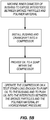
- the compressor 22 may be assembled using oil as the lubricant rather than grease, the process for which is shown in FIG. 5B .
- the bushing 14 is machined and the crankshaft journal 24 is polished and hardened, the bushing 14 and the crankshaft 18 are installed into the compressor 22. Oil is then provided to a sump within the compressor 22.
- the compressor 22 is operated on a test stand long enough to pump oil to the bushing 14 and to push oil into the interstices 46 and the valleys 54 by hydrodynamic pressure.
Landscapes
- Engineering & Computer Science (AREA)
- General Engineering & Computer Science (AREA)
- Mechanical Engineering (AREA)
- Compressor (AREA)
- Applications Or Details Of Rotary Compressors (AREA)
- Sliding-Contact Bearings (AREA)
- Lubricants (AREA)
- Powder Metallurgy (AREA)
Claims (13)
- Anordnung, umfassend:eine Verbund-Metall-Polymer-Buchse (14) miteiner äußeren Metallschicht (26) mit einer Innenfläche (30), wobei Metallpartikel (34) auf die Innenfläche (30) gesintert sind,einem Polymermaterial (38), das zwischen den Metallpartikeln (34) angeordnet ist,einer fertigen Innenfläche (48), die sowohl durch das Polymermaterial (38) als auch die freiliegenden Teile der Metallpartikel (34) definiert wird,einer Vielzahl von kleinen Zwischenräumen (46), die zwischen den Metallpartikeln (34) und dem Polymermaterial (38) ausgebildet sind, undeiner Vielzahl von Gratrippen (50), die durch das über die Metallpartikel (34) hinausragende Polymermaterial (38) definiert werden, wobei die Gratrippen (50) mindestens etwa 8% der Fläche der fertigen Innenfläche (48) einnehmen; undeine Kurbelwelle (18) mit einem zumindest teilweise in der Buchse (14) aufgenommenen und von der fertigen Innenfläche (48) getragenen Wellenzapfen (24), wobei der Wellenzapfen (24) auf eine Oberflächengüte von etwa 0,1 Mikrometer oder kleiner poliert ist, um die Verschleißrate der Buchse (14) zu reduzieren.
- Anordnung gemäß Anspruch 1, wobei zumindest einige der kleinen Zwischenräume der fertigen Innenfläche (48) offengelegt sind und gegebenenfalls ein Gleitmittel enthalten, das die kleinen Zwischenräume (46) zumindest teilweise füllt.
- Anordnung gemäß Anspruch 1 mit
einer Vielzahl von Vertiefungen (54), die durch das Polymermaterial (38) auf der fertigen Innenfläche (48) definiert werden und
einem Gleitmittel, das die Vertiefungen (54) zumindest teilweise füllt. - Anordnung gemäß Anspruch 1, wobei das Polymermaterial (38) Polytetrafluorethylen enthält.
- Anordnung gemäß Anspruch 1, wobei der Wellenzapfen (24) auf mindestens etwa 55 HRC (Rockwellhärteskala) gehärtet ist, um eine Einlagerung von Fremdkörpern im Wellenzapfen (24) zu verhindern.
- Anordnung gemäß Anspruch 1 mit einem luftdichten Kältemittelscrollverdichter (22), in dem die Kurbelwelle (18) und die Buchse eingebaut sind.
- Anordnung gemäß Anspruch 1, wobei die Gratrippen (54) um mindestens etwa 10 Mikrometer über die Metallpartikel (34) vorstehen.
- Verfahren zum Zusammenbau einer Verbund-Metall-Polymer-Buchse (14) und einer Kurbelwelle (18), wobei die Buchse (14) eine äußere Metallschicht (26) aufweist, Metallteilchen (34) auf die Innenfläche (30) der äußeren Metallschicht (26) gesintert sind und ein Polymermaterial (38) zwischen den Metallpartikeln (34) angeordnet ist, wobei das Verfahren umfasst:Anbohren der Innenfläche der Buchse (14), um die Metallteilchen (34) zumindest teilweise freizulegen und dadurch eine fertige Innenfläche (48) zu bilden, die sowohl durch das Polymermaterial (38) als auch die freiliegenden Teile der Metallpartikel (34) definiert wird;der Bohrschritt bildet Gratrippen (50) im Polymermaterial (38), das über die Metallpartikel (34) vorsteht und mindestens etwa 8% der Fläche der fertigen Innenfläche (48) einnimmt;Polieren des Wellenzapfens (24) der Kurbelwelle (18) auf eine Oberflächengüte von etwa 0,1 Mikrometer oder kleiner;Einsetzen des polierten Wellenzapfens (24) in die Buchse (14); undLagern des Wellenzapfens (24) in der fertigen Innenfläche (48) der Buchse (14), gegebenenfallsworin der Bohrschritt umfasstDrehen der Buchse (14) relativ zu einem Schneidwerkzeug und Verschieben des Schneidwerkzeugs in Richtung der Buchse (14) mit einer Vorschubgeschwindigkeit zwischen etwa 0,07112 mm (0,0028 Zoll) pro Umdrehung der Buchse (14) und etwa 0,1422 mm (0,0056 Zoll) pro Umdrehung der Buchse (14).
- Verfahren zum Zusammenbau eines Kompressors (22), wobei das Verfahren die Durchführung des Verfahrens gemäß Anspruch 8 umfasst und ferner umfasst
Positionieren der Buchse (14) und der Kurbelwelle (18) im Gehäuse des Kompressors (22). - Verfahren gemäß Anspruch 8 oder 9, wobei die Buchse (14) ferner eine Vielzahl von kleinen, zwischen den Metallpartikeln (34) und dem Polymermaterial (38) gebildeten Zwischenräumen (46) aufweist und wobei der Bohrschritt ferner das Bloßlegen zumindest einiger der kleinen Zwischenräume (46) auf der fertigen Innenfläche (48) umfasst.
- Verfahren gemäß Anspruch 10, welches dadurch gekennzeichnet ist, dass vor dem Einsetzen des polierten Wellenzapfens (24) in die Buchse (14) Gleitmittel auf die fertige Innenfläche (48) und den Wellenzapfen (24) aufgebracht wird.
- Das Verfahren gemäß Anspruch 11 ferner umfassend:Drehen des Kurbelwellenzapfens (24) relativ zur Buchse (14) nach dem Aufbringen von Gleitmittel auf die fertige Innenfläche (48) und den Wellenzapfen (24); undEinsatz des hydrodynamischen Drucks, der zwischen dem Wellenzapfen (24) und dem Lager gebildet wird, um die kleinen Zwischenräume (46) zumindest teilweise mit Gleitmittel zu füllen und bei Abhängigkeit von Anspruch 9 gegebenenfalls das Betreiben des Kompressors (22) auf einem Prüfstand umfasst, um den hydrodynamischen Druck zu erzeugen.
- Das Verfahren gemäß Anspruch 11 im Bohrschritt ferner umfassend:Ausbildung von Vertiefungen (54) im Polymermaterial auf der fertigen Innenfläche (48), wobei das Verfahren ferner umfasstDrehen des Kurbelwellenzapfens relativ zur Buchse (14) nach dem Aufbringen von Gleitmittel auf die fertige Innenfläche und den Wellenzapfen; undEinsatz des hydrodynamischen Drucks, der zwischen dem Wellenzapfen (24) und dem Lager gebildet wird, um die kleinen Zwischenräume (54) zumindest teilweise mit Gleitmittel zu füllen.
Applications Claiming Priority (2)
| Application Number | Priority Date | Filing Date | Title |
|---|---|---|---|
| US13/103,793 US8613555B2 (en) | 2011-05-09 | 2011-05-09 | Composite metal-polymer bushing and crankshaft assembly |
| PCT/US2012/036510 WO2012154558A2 (en) | 2011-05-09 | 2012-05-04 | Composite metal-polymer bushing and crankshaft assembly |
Publications (3)
| Publication Number | Publication Date |
|---|---|
| EP2707600A2 EP2707600A2 (de) | 2014-03-19 |
| EP2707600A4 EP2707600A4 (de) | 2015-05-06 |
| EP2707600B1 true EP2707600B1 (de) | 2017-07-12 |
Family
ID=47139908
Family Applications (1)
| Application Number | Title | Priority Date | Filing Date |
|---|---|---|---|
| EP12782209.6A Active EP2707600B1 (de) | 2011-05-09 | 2012-05-04 | Baugruppe aus einer verbundmetall-polymer-buchse und einer kurbelwelle |
Country Status (5)
| Country | Link |
|---|---|
| US (1) | US8613555B2 (de) |
| EP (1) | EP2707600B1 (de) |
| CN (1) | CN103608591B (de) |
| BR (1) | BR112013028703B1 (de) |
| WO (1) | WO2012154558A2 (de) |
Families Citing this family (6)
| Publication number | Priority date | Publication date | Assignee | Title |
|---|---|---|---|---|
| EP3851504B1 (de) | 2014-11-11 | 2024-10-02 | Trane International Inc. | Kühlmittelzusammensetzungen |
| US9556372B2 (en) | 2014-11-26 | 2017-01-31 | Trane International Inc. | Refrigerant compositions |
| US10125809B2 (en) * | 2016-08-01 | 2018-11-13 | GM Global Technology Operations LLC | Crankshaft assemblies and methods of manufacturing the same |
| JP7656503B2 (ja) * | 2021-06-29 | 2025-04-03 | 大同メタル工業株式会社 | 摺動部材 |
| DE102022121689B4 (de) * | 2022-08-26 | 2025-10-16 | Federal-Mogul Wiesbaden Gmbh | Leitfähiges selbstschmierendes Gleitelement |
| US12116936B2 (en) | 2023-01-20 | 2024-10-15 | Honeywell International Inc. | Mounting system for gearbox including corrugated bushing |
Family Cites Families (32)
| Publication number | Priority date | Publication date | Assignee | Title |
|---|---|---|---|---|
| US3416941A (en) | 1963-05-16 | 1968-12-17 | Daikin Ind Ltd | Process for the manufacture of a bearing surface on a steel article including a single sintered layer of bronze particles and a layer of polytetrafluoroethylene |
| US3342667A (en) * | 1963-08-23 | 1967-09-19 | Woodmont Products Inc | Dry fluorocarbon bearing material |
| US3632459A (en) * | 1969-10-24 | 1972-01-04 | Glyco Metall Werke | Process for the manufacture of slide bearings, in particular compound bearings |
| US4189522A (en) | 1975-08-08 | 1980-02-19 | Daido Metal Company, Ltd. | Multi-layer sliding material and method for manufacturing the same |
| JPS53113876A (en) | 1977-03-15 | 1978-10-04 | Daido Metal Co Ltd | Metallbacked slideerequired member |
| JPS5445440A (en) | 1977-09-19 | 1979-04-10 | Oiles Industry Co Ltd | Double layer bearing and method of producing same |
| JPS59194128A (ja) | 1983-04-15 | 1984-11-02 | Hitachi Ltd | 冷凍機用圧縮機の軸受 |
| US4582368A (en) | 1985-05-06 | 1986-04-15 | Ndc Company, Ltd. | Dry bearing |
| JPS62200018A (ja) | 1986-02-25 | 1987-09-03 | Matsushita Refrig Co | 冷凍機用圧縮機の軸受 |
| DE3728951A1 (de) | 1987-08-29 | 1989-03-09 | Kolbenschmidt Ag | Gerollte buchse fuer gleitlager |
| JP2512150B2 (ja) | 1989-05-31 | 1996-07-03 | 松下電器産業株式会社 | 冷凍空調用スクロ―ルコンプレッサ |
| JPH03194210A (ja) | 1989-12-25 | 1991-08-23 | Toshiba Corp | ロータリコンプレッサ用軸受 |
| JPH0598315A (ja) | 1991-10-03 | 1993-04-20 | Mitsubishi Materials Corp | 焼結含油軸受の製造方法及び焼結体用バニシング加工機 |
| JP3194210B2 (ja) | 1992-03-31 | 2001-07-30 | ヤマハ蒲郡製造株式会社 | 樹脂マット作成方法及び樹脂マット作成装置 |
| JP3003988B2 (ja) | 1996-09-10 | 2000-01-31 | 日本碍子株式会社 | セラミックス円筒体の曲げ強度試験方法及び試験装置 |
| JPH11153091A (ja) * | 1997-09-18 | 1999-06-08 | Matsushita Electric Ind Co Ltd | 摺動部材とそれを用いた冷凍圧縮機 |
| US6082495A (en) | 1998-02-25 | 2000-07-04 | Copeland Corporation | Scroll compressor bearing lubrication |
| JP2006090330A (ja) | 1998-07-29 | 2006-04-06 | Daikin Ind Ltd | 冷凍機用圧縮機 |
| JP4325611B2 (ja) | 1998-07-29 | 2009-09-02 | ダイキン工業株式会社 | 冷凍機用圧縮機の軸受および冷凍機用圧縮機 |
| EP1845261A3 (de) | 1998-07-29 | 2008-06-11 | Daikin Industries, Ltd. | Lagerung für einen Kühlkompressor |
| JP3679312B2 (ja) * | 2000-06-15 | 2005-08-03 | 大同メタル工業株式会社 | 複層摺動材料 |
| JP2003184883A (ja) * | 2001-12-20 | 2003-07-03 | Nissan Motor Co Ltd | 軸受摺動部材 |
| ITMI20012826A1 (it) * | 2001-12-28 | 2003-06-28 | Nuovo Pignone Spa | Elemento di tenuta ad usura ridotta in particolare per cilindri e pistoni di compressori alternativi |
| JP2005133657A (ja) | 2003-10-31 | 2005-05-26 | Hitachi Home & Life Solutions Inc | スクロール圧縮機 |
| WO2006035680A1 (ja) | 2004-09-28 | 2006-04-06 | Daikin Industries, Ltd. | 摺動部材及び流体機械 |
| CN101027486A (zh) | 2004-09-28 | 2007-08-29 | 大金工业株式会社 | 摩擦部件及流体机械 |
| JP2006283706A (ja) * | 2005-04-01 | 2006-10-19 | Daikin Ind Ltd | 摺動部材用組成物、摺動部材及び流体機械 |
| US7739279B2 (en) | 2005-12-12 | 2010-06-15 | Fuji Xerox Co., Ltd. | Systems and methods for determining relevant information based on document structure |
| CN101517252B (zh) | 2006-09-28 | 2011-04-13 | 大金工业株式会社 | 滑动部件以及使用了该滑动部件的流体机械 |
| CN101535420B (zh) * | 2006-10-30 | 2016-05-11 | 安德鲁·W·苏曼 | 可磨耗干膜润滑剂和其涂敷方法以及由此制成的物品 |
| US8679641B2 (en) | 2007-01-05 | 2014-03-25 | David M. Saxton | Wear resistant lead free alloy bushing and method of making |
| US20110167587A1 (en) | 2009-02-03 | 2011-07-14 | Harry Shimp | Method of Manufacturing Composite Bushing Substrate |
-
2011
- 2011-05-09 US US13/103,793 patent/US8613555B2/en active Active
-
2012
- 2012-05-04 WO PCT/US2012/036510 patent/WO2012154558A2/en not_active Ceased
- 2012-05-04 BR BR112013028703-9A patent/BR112013028703B1/pt active IP Right Grant
- 2012-05-04 CN CN201280028935.XA patent/CN103608591B/zh active Active
- 2012-05-04 EP EP12782209.6A patent/EP2707600B1/de active Active
Also Published As
| Publication number | Publication date |
|---|---|
| CN103608591A (zh) | 2014-02-26 |
| BR112013028703A2 (pt) | 2017-01-24 |
| CN103608591B (zh) | 2016-11-16 |
| EP2707600A2 (de) | 2014-03-19 |
| WO2012154558A3 (en) | 2013-01-03 |
| BR112013028703B1 (pt) | 2022-11-16 |
| EP2707600A4 (de) | 2015-05-06 |
| WO2012154558A2 (en) | 2012-11-15 |
| US8613555B2 (en) | 2013-12-24 |
| US20120288392A1 (en) | 2012-11-15 |
Similar Documents
| Publication | Publication Date | Title |
|---|---|---|
| EP2707600B1 (de) | Baugruppe aus einer verbundmetall-polymer-buchse und einer kurbelwelle | |
| CN110043564B (zh) | 烧结轴承的制造方法、以及振动电机 | |
| JP3929440B2 (ja) | 電動機 | |
| TR201816164T4 (tr) | Salyangoz kompresör. | |
| CN105298837A (zh) | 电动泵单元 | |
| CA2697144C (en) | New and improved esp motor design | |
| JP5996455B2 (ja) | スクロール圧縮機 | |
| JP2001065458A (ja) | 圧縮機 | |
| JP2001323928A (ja) | スラスト軸受 | |
| JP3823325B2 (ja) | 冷凍機用圧縮機の軸受および冷凍機用圧縮機 | |
| JP5963854B2 (ja) | 回転機械および冷凍サイクル機器 | |
| CN203570586U (zh) | 一种内啮合齿轮泵 | |
| JP2002147354A (ja) | 圧縮機 | |
| JPWO2000006902A1 (ja) | 冷凍機用圧縮機の軸受および冷凍機用圧縮機 | |
| US9593682B2 (en) | Hydrodynamic bearing applied on a contact interface of a fluid compressor based on a spiral type mechanism | |
| GB2342956A (en) | Cantilever mount orbiting scroll with slide bearings for adjustment of shaft misalignment | |
| JP6805556B2 (ja) | すべり軸受を有する圧縮機 | |
| JP2000356223A (ja) | 油潤滑軸受構造及びこれを備えるポンプ、変速機、回転駆動機、並びにポンプ設備 | |
| JP5640885B2 (ja) | スクロール型圧縮機 | |
| GB2537857A (en) | Thrust washer comprising a polymer running layer having a textured surface | |
| JP2004251226A (ja) | スクロール圧縮機 | |
| US6099278A (en) | Cantilever mount orbiting scroll with shaft adjustment | |
| CN117108623A (zh) | 轴承及制造方法 | |
| JP4325611B2 (ja) | 冷凍機用圧縮機の軸受および冷凍機用圧縮機 | |
| JP2009085039A (ja) | 冷媒圧縮機 |
Legal Events
| Date | Code | Title | Description |
|---|---|---|---|
| PUAI | Public reference made under article 153(3) epc to a published international application that has entered the european phase |
Free format text: ORIGINAL CODE: 0009012 |
|
| 17P | Request for examination filed |
Effective date: 20131108 |
|
| AK | Designated contracting states |
Kind code of ref document: A2 Designated state(s): AL AT BE BG CH CY CZ DE DK EE ES FI FR GB GR HR HU IE IS IT LI LT LU LV MC MK MT NL NO PL PT RO RS SE SI SK SM TR |
|
| DAX | Request for extension of the european patent (deleted) | ||
| A4 | Supplementary search report drawn up and despatched |
Effective date: 20150410 |
|
| RIC1 | Information provided on ipc code assigned before grant |
Ipc: F16C 33/24 20060101ALI20150405BHEP Ipc: F04C 29/02 20060101AFI20150405BHEP Ipc: F04C 18/02 20060101ALI20150405BHEP Ipc: F04C 18/07 20060101ALI20150405BHEP Ipc: F04C 23/00 20060101ALI20150405BHEP |
|
| 17Q | First examination report despatched |
Effective date: 20160817 |
|
| STAA | Information on the status of an ep patent application or granted ep patent |
Free format text: STATUS: EXAMINATION IS IN PROGRESS |
|
| GRAP | Despatch of communication of intention to grant a patent |
Free format text: ORIGINAL CODE: EPIDOSNIGR1 |
|
| STAA | Information on the status of an ep patent application or granted ep patent |
Free format text: STATUS: GRANT OF PATENT IS INTENDED |
|
| INTG | Intention to grant announced |
Effective date: 20170127 |
|
| RIN1 | Information on inventor provided before grant (corrected) |
Inventor name: LEPAK, DERRICK J. Inventor name: JANDA, DAVID Inventor name: BENCO, MICHAEL G. Inventor name: LAPP, WILLIAM E. Inventor name: BUTTERWORTH, ARTHER L. Inventor name: DORMAN, DENNIS R. |
|
| GRAS | Grant fee paid |
Free format text: ORIGINAL CODE: EPIDOSNIGR3 |
|
| GRAA | (expected) grant |
Free format text: ORIGINAL CODE: 0009210 |
|
| STAA | Information on the status of an ep patent application or granted ep patent |
Free format text: STATUS: THE PATENT HAS BEEN GRANTED |
|
| AK | Designated contracting states |
Kind code of ref document: B1 Designated state(s): AL AT BE BG CH CY CZ DE DK EE ES FI FR GB GR HR HU IE IS IT LI LT LU LV MC MK MT NL NO PL PT RO RS SE SI SK SM TR |
|
| REG | Reference to a national code |
Ref country code: GB Ref legal event code: FG4D |
|
| REG | Reference to a national code |
Ref country code: CH Ref legal event code: EP |
|
| REG | Reference to a national code |
Ref country code: AT Ref legal event code: REF Ref document number: 908621 Country of ref document: AT Kind code of ref document: T Effective date: 20170715 |
|
| REG | Reference to a national code |
Ref country code: IE Ref legal event code: FG4D |
|
| REG | Reference to a national code |
Ref country code: DE Ref legal event code: R096 Ref document number: 602012034486 Country of ref document: DE |
|
| REG | Reference to a national code |
Ref country code: NL Ref legal event code: MP Effective date: 20170712 |
|
| REG | Reference to a national code |
Ref country code: LT Ref legal event code: MG4D |
|
| REG | Reference to a national code |
Ref country code: AT Ref legal event code: MK05 Ref document number: 908621 Country of ref document: AT Kind code of ref document: T Effective date: 20170712 |
|
| PG25 | Lapsed in a contracting state [announced via postgrant information from national office to epo] |
Ref country code: HR Free format text: LAPSE BECAUSE OF FAILURE TO SUBMIT A TRANSLATION OF THE DESCRIPTION OR TO PAY THE FEE WITHIN THE PRESCRIBED TIME-LIMIT Effective date: 20170712 Ref country code: NL Free format text: LAPSE BECAUSE OF FAILURE TO SUBMIT A TRANSLATION OF THE DESCRIPTION OR TO PAY THE FEE WITHIN THE PRESCRIBED TIME-LIMIT Effective date: 20170712 Ref country code: AT Free format text: LAPSE BECAUSE OF FAILURE TO SUBMIT A TRANSLATION OF THE DESCRIPTION OR TO PAY THE FEE WITHIN THE PRESCRIBED TIME-LIMIT Effective date: 20170712 Ref country code: NO Free format text: LAPSE BECAUSE OF FAILURE TO SUBMIT A TRANSLATION OF THE DESCRIPTION OR TO PAY THE FEE WITHIN THE PRESCRIBED TIME-LIMIT Effective date: 20171012 Ref country code: FI Free format text: LAPSE BECAUSE OF FAILURE TO SUBMIT A TRANSLATION OF THE DESCRIPTION OR TO PAY THE FEE WITHIN THE PRESCRIBED TIME-LIMIT Effective date: 20170712 Ref country code: SE Free format text: LAPSE BECAUSE OF FAILURE TO SUBMIT A TRANSLATION OF THE DESCRIPTION OR TO PAY THE FEE WITHIN THE PRESCRIBED TIME-LIMIT Effective date: 20170712 Ref country code: LT Free format text: LAPSE BECAUSE OF FAILURE TO SUBMIT A TRANSLATION OF THE DESCRIPTION OR TO PAY THE FEE WITHIN THE PRESCRIBED TIME-LIMIT Effective date: 20170712 |
|
| PG25 | Lapsed in a contracting state [announced via postgrant information from national office to epo] |
Ref country code: IS Free format text: LAPSE BECAUSE OF FAILURE TO SUBMIT A TRANSLATION OF THE DESCRIPTION OR TO PAY THE FEE WITHIN THE PRESCRIBED TIME-LIMIT Effective date: 20171112 Ref country code: PL Free format text: LAPSE BECAUSE OF FAILURE TO SUBMIT A TRANSLATION OF THE DESCRIPTION OR TO PAY THE FEE WITHIN THE PRESCRIBED TIME-LIMIT Effective date: 20170712 Ref country code: ES Free format text: LAPSE BECAUSE OF FAILURE TO SUBMIT A TRANSLATION OF THE DESCRIPTION OR TO PAY THE FEE WITHIN THE PRESCRIBED TIME-LIMIT Effective date: 20170712 Ref country code: GR Free format text: LAPSE BECAUSE OF FAILURE TO SUBMIT A TRANSLATION OF THE DESCRIPTION OR TO PAY THE FEE WITHIN THE PRESCRIBED TIME-LIMIT Effective date: 20171013 Ref country code: BG Free format text: LAPSE BECAUSE OF FAILURE TO SUBMIT A TRANSLATION OF THE DESCRIPTION OR TO PAY THE FEE WITHIN THE PRESCRIBED TIME-LIMIT Effective date: 20171012 Ref country code: RS Free format text: LAPSE BECAUSE OF FAILURE TO SUBMIT A TRANSLATION OF THE DESCRIPTION OR TO PAY THE FEE WITHIN THE PRESCRIBED TIME-LIMIT Effective date: 20170712 Ref country code: LV Free format text: LAPSE BECAUSE OF FAILURE TO SUBMIT A TRANSLATION OF THE DESCRIPTION OR TO PAY THE FEE WITHIN THE PRESCRIBED TIME-LIMIT Effective date: 20170712 |
|
| REG | Reference to a national code |
Ref country code: DE Ref legal event code: R097 Ref document number: 602012034486 Country of ref document: DE |
|
| REG | Reference to a national code |
Ref country code: FR Ref legal event code: PLFP Year of fee payment: 7 |
|
| PG25 | Lapsed in a contracting state [announced via postgrant information from national office to epo] |
Ref country code: RO Free format text: LAPSE BECAUSE OF FAILURE TO SUBMIT A TRANSLATION OF THE DESCRIPTION OR TO PAY THE FEE WITHIN THE PRESCRIBED TIME-LIMIT Effective date: 20170712 Ref country code: DK Free format text: LAPSE BECAUSE OF FAILURE TO SUBMIT A TRANSLATION OF THE DESCRIPTION OR TO PAY THE FEE WITHIN THE PRESCRIBED TIME-LIMIT Effective date: 20170712 Ref country code: CZ Free format text: LAPSE BECAUSE OF FAILURE TO SUBMIT A TRANSLATION OF THE DESCRIPTION OR TO PAY THE FEE WITHIN THE PRESCRIBED TIME-LIMIT Effective date: 20170712 |
|
| PLBE | No opposition filed within time limit |
Free format text: ORIGINAL CODE: 0009261 |
|
| STAA | Information on the status of an ep patent application or granted ep patent |
Free format text: STATUS: NO OPPOSITION FILED WITHIN TIME LIMIT |
|
| PG25 | Lapsed in a contracting state [announced via postgrant information from national office to epo] |
Ref country code: IT Free format text: LAPSE BECAUSE OF FAILURE TO SUBMIT A TRANSLATION OF THE DESCRIPTION OR TO PAY THE FEE WITHIN THE PRESCRIBED TIME-LIMIT Effective date: 20170712 Ref country code: SK Free format text: LAPSE BECAUSE OF FAILURE TO SUBMIT A TRANSLATION OF THE DESCRIPTION OR TO PAY THE FEE WITHIN THE PRESCRIBED TIME-LIMIT Effective date: 20170712 Ref country code: SM Free format text: LAPSE BECAUSE OF FAILURE TO SUBMIT A TRANSLATION OF THE DESCRIPTION OR TO PAY THE FEE WITHIN THE PRESCRIBED TIME-LIMIT Effective date: 20170712 Ref country code: EE Free format text: LAPSE BECAUSE OF FAILURE TO SUBMIT A TRANSLATION OF THE DESCRIPTION OR TO PAY THE FEE WITHIN THE PRESCRIBED TIME-LIMIT Effective date: 20170712 |
|
| 26N | No opposition filed |
Effective date: 20180413 |
|
| PG25 | Lapsed in a contracting state [announced via postgrant information from national office to epo] |
Ref country code: SI Free format text: LAPSE BECAUSE OF FAILURE TO SUBMIT A TRANSLATION OF THE DESCRIPTION OR TO PAY THE FEE WITHIN THE PRESCRIBED TIME-LIMIT Effective date: 20170712 |
|
| REG | Reference to a national code |
Ref country code: CH Ref legal event code: PL |
|
| REG | Reference to a national code |
Ref country code: BE Ref legal event code: MM Effective date: 20180531 |
|
| PG25 | Lapsed in a contracting state [announced via postgrant information from national office to epo] |
Ref country code: MC Free format text: LAPSE BECAUSE OF FAILURE TO SUBMIT A TRANSLATION OF THE DESCRIPTION OR TO PAY THE FEE WITHIN THE PRESCRIBED TIME-LIMIT Effective date: 20170712 |
|
| REG | Reference to a national code |
Ref country code: IE Ref legal event code: MM4A |
|
| PG25 | Lapsed in a contracting state [announced via postgrant information from national office to epo] |
Ref country code: CH Free format text: LAPSE BECAUSE OF NON-PAYMENT OF DUE FEES Effective date: 20180531 Ref country code: LI Free format text: LAPSE BECAUSE OF NON-PAYMENT OF DUE FEES Effective date: 20180531 |
|
| PG25 | Lapsed in a contracting state [announced via postgrant information from national office to epo] |
Ref country code: LU Free format text: LAPSE BECAUSE OF NON-PAYMENT OF DUE FEES Effective date: 20180504 |
|
| PG25 | Lapsed in a contracting state [announced via postgrant information from national office to epo] |
Ref country code: IE Free format text: LAPSE BECAUSE OF NON-PAYMENT OF DUE FEES Effective date: 20180504 |
|
| PG25 | Lapsed in a contracting state [announced via postgrant information from national office to epo] |
Ref country code: BE Free format text: LAPSE BECAUSE OF NON-PAYMENT OF DUE FEES Effective date: 20180531 |
|
| PG25 | Lapsed in a contracting state [announced via postgrant information from national office to epo] |
Ref country code: MT Free format text: LAPSE BECAUSE OF NON-PAYMENT OF DUE FEES Effective date: 20180504 |
|
| PG25 | Lapsed in a contracting state [announced via postgrant information from national office to epo] |
Ref country code: TR Free format text: LAPSE BECAUSE OF FAILURE TO SUBMIT A TRANSLATION OF THE DESCRIPTION OR TO PAY THE FEE WITHIN THE PRESCRIBED TIME-LIMIT Effective date: 20170712 |
|
| PG25 | Lapsed in a contracting state [announced via postgrant information from national office to epo] |
Ref country code: PT Free format text: LAPSE BECAUSE OF FAILURE TO SUBMIT A TRANSLATION OF THE DESCRIPTION OR TO PAY THE FEE WITHIN THE PRESCRIBED TIME-LIMIT Effective date: 20170712 Ref country code: HU Free format text: LAPSE BECAUSE OF FAILURE TO SUBMIT A TRANSLATION OF THE DESCRIPTION OR TO PAY THE FEE WITHIN THE PRESCRIBED TIME-LIMIT; INVALID AB INITIO Effective date: 20120504 |
|
| PG25 | Lapsed in a contracting state [announced via postgrant information from national office to epo] |
Ref country code: CY Free format text: LAPSE BECAUSE OF FAILURE TO SUBMIT A TRANSLATION OF THE DESCRIPTION OR TO PAY THE FEE WITHIN THE PRESCRIBED TIME-LIMIT Effective date: 20170712 Ref country code: MK Free format text: LAPSE BECAUSE OF NON-PAYMENT OF DUE FEES Effective date: 20170712 |
|
| PG25 | Lapsed in a contracting state [announced via postgrant information from national office to epo] |
Ref country code: AL Free format text: LAPSE BECAUSE OF FAILURE TO SUBMIT A TRANSLATION OF THE DESCRIPTION OR TO PAY THE FEE WITHIN THE PRESCRIBED TIME-LIMIT Effective date: 20170712 |
|
| REG | Reference to a national code |
Ref country code: DE Ref legal event code: R082 Ref document number: 602012034486 Country of ref document: DE Representative=s name: HL KEMPNER PATENTANWAELTE, SOLICITORS (ENGLAND, DE Ref country code: DE Ref legal event code: R082 Ref document number: 602012034486 Country of ref document: DE Representative=s name: HL KEMPNER PATENTANWALT, RECHTSANWALT, SOLICIT, DE Ref country code: DE Ref legal event code: R082 Ref document number: 602012034486 Country of ref document: DE Representative=s name: HL KEMPNER PARTG MBB, DE |
|
| P01 | Opt-out of the competence of the unified patent court (upc) registered |
Effective date: 20230505 |
|
| PGFP | Annual fee paid to national office [announced via postgrant information from national office to epo] |
Ref country code: DE Payment date: 20250423 Year of fee payment: 14 |
|
| PGFP | Annual fee paid to national office [announced via postgrant information from national office to epo] |
Ref country code: GB Payment date: 20250423 Year of fee payment: 14 |
|
| PGFP | Annual fee paid to national office [announced via postgrant information from national office to epo] |
Ref country code: FR Payment date: 20250423 Year of fee payment: 14 |