EP2707265B1 - Verfahren zur aktivierung eines verbrennungsmotors für ein fahrzeug sowie entsprechende steuerung und fahrzeug - Google Patents
Verfahren zur aktivierung eines verbrennungsmotors für ein fahrzeug sowie entsprechende steuerung und fahrzeug Download PDFInfo
- Publication number
- EP2707265B1 EP2707265B1 EP12718085.9A EP12718085A EP2707265B1 EP 2707265 B1 EP2707265 B1 EP 2707265B1 EP 12718085 A EP12718085 A EP 12718085A EP 2707265 B1 EP2707265 B1 EP 2707265B1
- Authority
- EP
- European Patent Office
- Prior art keywords
- vehicle
- drive torque
- internal combustion
- combustion engine
- torque
- Prior art date
- Legal status (The legal status is an assumption and is not a legal conclusion. Google has not performed a legal analysis and makes no representation as to the accuracy of the status listed.)
- Active
Links
Images
Classifications
-
- B—PERFORMING OPERATIONS; TRANSPORTING
- B60—VEHICLES IN GENERAL
- B60W—CONJOINT CONTROL OF VEHICLE SUB-UNITS OF DIFFERENT TYPE OR DIFFERENT FUNCTION; CONTROL SYSTEMS SPECIALLY ADAPTED FOR HYBRID VEHICLES; ROAD VEHICLE DRIVE CONTROL SYSTEMS FOR PURPOSES NOT RELATED TO THE CONTROL OF A PARTICULAR SUB-UNIT
- B60W10/00—Conjoint control of vehicle sub-units of different type or different function
- B60W10/04—Conjoint control of vehicle sub-units of different type or different function including control of propulsion units
- B60W10/06—Conjoint control of vehicle sub-units of different type or different function including control of propulsion units including control of combustion engines
-
- B—PERFORMING OPERATIONS; TRANSPORTING
- B60—VEHICLES IN GENERAL
- B60W—CONJOINT CONTROL OF VEHICLE SUB-UNITS OF DIFFERENT TYPE OR DIFFERENT FUNCTION; CONTROL SYSTEMS SPECIALLY ADAPTED FOR HYBRID VEHICLES; ROAD VEHICLE DRIVE CONTROL SYSTEMS FOR PURPOSES NOT RELATED TO THE CONTROL OF A PARTICULAR SUB-UNIT
- B60W20/00—Control systems specially adapted for hybrid vehicles
- B60W20/10—Controlling the power contribution of each of the prime movers to meet required power demand
- B60W20/11—Controlling the power contribution of each of the prime movers to meet required power demand using model predictive control [MPC] strategies, i.e. control methods based on models predicting performance
-
- B—PERFORMING OPERATIONS; TRANSPORTING
- B60—VEHICLES IN GENERAL
- B60W—CONJOINT CONTROL OF VEHICLE SUB-UNITS OF DIFFERENT TYPE OR DIFFERENT FUNCTION; CONTROL SYSTEMS SPECIALLY ADAPTED FOR HYBRID VEHICLES; ROAD VEHICLE DRIVE CONTROL SYSTEMS FOR PURPOSES NOT RELATED TO THE CONTROL OF A PARTICULAR SUB-UNIT
- B60W10/00—Conjoint control of vehicle sub-units of different type or different function
- B60W10/04—Conjoint control of vehicle sub-units of different type or different function including control of propulsion units
- B60W10/08—Conjoint control of vehicle sub-units of different type or different function including control of propulsion units including control of electric propulsion units, e.g. motors or generators
-
- B—PERFORMING OPERATIONS; TRANSPORTING
- B60—VEHICLES IN GENERAL
- B60W—CONJOINT CONTROL OF VEHICLE SUB-UNITS OF DIFFERENT TYPE OR DIFFERENT FUNCTION; CONTROL SYSTEMS SPECIALLY ADAPTED FOR HYBRID VEHICLES; ROAD VEHICLE DRIVE CONTROL SYSTEMS FOR PURPOSES NOT RELATED TO THE CONTROL OF A PARTICULAR SUB-UNIT
- B60W20/00—Control systems specially adapted for hybrid vehicles
-
- B—PERFORMING OPERATIONS; TRANSPORTING
- B60—VEHICLES IN GENERAL
- B60W—CONJOINT CONTROL OF VEHICLE SUB-UNITS OF DIFFERENT TYPE OR DIFFERENT FUNCTION; CONTROL SYSTEMS SPECIALLY ADAPTED FOR HYBRID VEHICLES; ROAD VEHICLE DRIVE CONTROL SYSTEMS FOR PURPOSES NOT RELATED TO THE CONTROL OF A PARTICULAR SUB-UNIT
- B60W30/00—Purposes of road vehicle drive control systems not related to the control of a particular sub-unit, e.g. of systems using conjoint control of vehicle sub-units
- B60W30/18—Propelling the vehicle
- B60W30/188—Controlling power parameters of the driveline, e.g. determining the required power
- B60W30/1882—Controlling power parameters of the driveline, e.g. determining the required power characterised by the working point of the engine, e.g. by using engine output chart
-
- B—PERFORMING OPERATIONS; TRANSPORTING
- B60—VEHICLES IN GENERAL
- B60W—CONJOINT CONTROL OF VEHICLE SUB-UNITS OF DIFFERENT TYPE OR DIFFERENT FUNCTION; CONTROL SYSTEMS SPECIALLY ADAPTED FOR HYBRID VEHICLES; ROAD VEHICLE DRIVE CONTROL SYSTEMS FOR PURPOSES NOT RELATED TO THE CONTROL OF A PARTICULAR SUB-UNIT
- B60W30/00—Purposes of road vehicle drive control systems not related to the control of a particular sub-unit, e.g. of systems using conjoint control of vehicle sub-units
- B60W30/18—Propelling the vehicle
- B60W30/192—Mitigating problems related to power-up or power-down of the driveline, e.g. start-up of a cold engine
-
- B—PERFORMING OPERATIONS; TRANSPORTING
- B60—VEHICLES IN GENERAL
- B60K—ARRANGEMENT OR MOUNTING OF PROPULSION UNITS OR OF TRANSMISSIONS IN VEHICLES; ARRANGEMENT OR MOUNTING OF PLURAL DIVERSE PRIME-MOVERS IN VEHICLES; AUXILIARY DRIVES FOR VEHICLES; INSTRUMENTATION OR DASHBOARDS FOR VEHICLES; ARRANGEMENTS IN CONNECTION WITH COOLING, AIR INTAKE, GAS EXHAUST OR FUEL SUPPLY OF PROPULSION UNITS IN VEHICLES
- B60K6/00—Arrangement or mounting of plural diverse prime-movers for mutual or common propulsion, e.g. hybrid propulsion systems comprising electric motors and internal combustion engines
- B60K6/20—Arrangement or mounting of plural diverse prime-movers for mutual or common propulsion, e.g. hybrid propulsion systems comprising electric motors and internal combustion engines the prime-movers consisting of electric motors and internal combustion engines, e.g. HEVs
-
- B—PERFORMING OPERATIONS; TRANSPORTING
- B60—VEHICLES IN GENERAL
- B60W—CONJOINT CONTROL OF VEHICLE SUB-UNITS OF DIFFERENT TYPE OR DIFFERENT FUNCTION; CONTROL SYSTEMS SPECIALLY ADAPTED FOR HYBRID VEHICLES; ROAD VEHICLE DRIVE CONTROL SYSTEMS FOR PURPOSES NOT RELATED TO THE CONTROL OF A PARTICULAR SUB-UNIT
- B60W2510/00—Input parameters relating to a particular sub-units
- B60W2510/08—Electric propulsion units
- B60W2510/083—Torque
-
- B—PERFORMING OPERATIONS; TRANSPORTING
- B60—VEHICLES IN GENERAL
- B60W—CONJOINT CONTROL OF VEHICLE SUB-UNITS OF DIFFERENT TYPE OR DIFFERENT FUNCTION; CONTROL SYSTEMS SPECIALLY ADAPTED FOR HYBRID VEHICLES; ROAD VEHICLE DRIVE CONTROL SYSTEMS FOR PURPOSES NOT RELATED TO THE CONTROL OF A PARTICULAR SUB-UNIT
- B60W2520/00—Input parameters relating to overall vehicle dynamics
- B60W2520/10—Longitudinal speed
-
- B—PERFORMING OPERATIONS; TRANSPORTING
- B60—VEHICLES IN GENERAL
- B60W—CONJOINT CONTROL OF VEHICLE SUB-UNITS OF DIFFERENT TYPE OR DIFFERENT FUNCTION; CONTROL SYSTEMS SPECIALLY ADAPTED FOR HYBRID VEHICLES; ROAD VEHICLE DRIVE CONTROL SYSTEMS FOR PURPOSES NOT RELATED TO THE CONTROL OF A PARTICULAR SUB-UNIT
- B60W2540/00—Input parameters relating to occupants
- B60W2540/10—Accelerator pedal position
-
- B—PERFORMING OPERATIONS; TRANSPORTING
- B60—VEHICLES IN GENERAL
- B60W—CONJOINT CONTROL OF VEHICLE SUB-UNITS OF DIFFERENT TYPE OR DIFFERENT FUNCTION; CONTROL SYSTEMS SPECIALLY ADAPTED FOR HYBRID VEHICLES; ROAD VEHICLE DRIVE CONTROL SYSTEMS FOR PURPOSES NOT RELATED TO THE CONTROL OF A PARTICULAR SUB-UNIT
- B60W2540/00—Input parameters relating to occupants
- B60W2540/10—Accelerator pedal position
- B60W2540/106—Rate of change
-
- B—PERFORMING OPERATIONS; TRANSPORTING
- B60—VEHICLES IN GENERAL
- B60W—CONJOINT CONTROL OF VEHICLE SUB-UNITS OF DIFFERENT TYPE OR DIFFERENT FUNCTION; CONTROL SYSTEMS SPECIALLY ADAPTED FOR HYBRID VEHICLES; ROAD VEHICLE DRIVE CONTROL SYSTEMS FOR PURPOSES NOT RELATED TO THE CONTROL OF A PARTICULAR SUB-UNIT
- B60W2710/00—Output or target parameters relating to a particular sub-units
- B60W2710/10—Change speed gearings
- B60W2710/1022—Input torque
-
- B—PERFORMING OPERATIONS; TRANSPORTING
- B60—VEHICLES IN GENERAL
- B60W—CONJOINT CONTROL OF VEHICLE SUB-UNITS OF DIFFERENT TYPE OR DIFFERENT FUNCTION; CONTROL SYSTEMS SPECIALLY ADAPTED FOR HYBRID VEHICLES; ROAD VEHICLE DRIVE CONTROL SYSTEMS FOR PURPOSES NOT RELATED TO THE CONTROL OF A PARTICULAR SUB-UNIT
- B60W50/00—Details of control systems for road vehicle drive control not related to the control of a particular sub-unit, e.g. process diagnostic or vehicle driver interfaces
- B60W50/08—Interaction between the driver and the control system
- B60W50/14—Means for informing the driver, warning the driver or prompting a driver intervention
-
- Y—GENERAL TAGGING OF NEW TECHNOLOGICAL DEVELOPMENTS; GENERAL TAGGING OF CROSS-SECTIONAL TECHNOLOGIES SPANNING OVER SEVERAL SECTIONS OF THE IPC; TECHNICAL SUBJECTS COVERED BY FORMER USPC CROSS-REFERENCE ART COLLECTIONS [XRACs] AND DIGESTS
- Y02—TECHNOLOGIES OR APPLICATIONS FOR MITIGATION OR ADAPTATION AGAINST CLIMATE CHANGE
- Y02T—CLIMATE CHANGE MITIGATION TECHNOLOGIES RELATED TO TRANSPORTATION
- Y02T10/00—Road transport of goods or passengers
- Y02T10/60—Other road transportation technologies with climate change mitigation effect
- Y02T10/62—Hybrid vehicles
Definitions
- the present invention relates to a method for activating an internal combustion engine of a vehicle (in particular of a hybrid vehicle) for driving the vehicle, as well as a correspondingly configured controller and a correspondingly configured vehicle.
- the WO 02/26520 A1 discloses a torque manager which operates an electric motor and an internal combustion engine depending on a target wheel torque.
- the DE 196 37 210 A1 describes a powertrain control, which controls depending on positions of the accelerator pedal and the brake pedal drive sources and decelerating units.
- the DE 698 31 468 T2 describes a drive control system with which a jerk is prevented which would otherwise be generated when an internal combustion engine is started while the vehicle is being driven by an electric motor.
- the internal combustion engine is started when the currently available drive torque is reached.
- the driver is notified via a pressure point on the accelerator, cf. eg DE 10 2008 000 577 , It is also known to delay the starting of the internal combustion engine. The duration of the delay depends on the accelerator pedal position, cf. EP-A-2 206 622 ,
- the internal combustion engine is started when the desired torque predetermined by the driver is above the torque that can be provided by the electric motor. Since the driver has no information as to when the desired torque, which is generally predetermined via the accelerator pedal, is greater than the torque provided by the electric motor, it is difficult for the driver to drive his vehicle exclusively with the electric motor.
- the present invention has the object, at least to facilitate the possibility of operating a vehicle only by the electric motor.
- a method for activating an internal combustion engine for a vehicle is provided.
- the vehicle is an electric motor and the internal combustion engine, which are both designed to drive the vehicle.
- the internal combustion engine is automatically activated when a predetermined, for example via an accelerator pedal of the vehicle target drive torque is greater than a sum of moments.
- this torque sum is composed of a drive torque which can currently be provided by the electric motor and an additional torque which is greater than 0.
- Under the currently provided by the electric motor drive torque is understood to mean the drive torque, which can be made available at the maximum time of the electric motor for driving the vehicle at the respective time.
- the driver By not already activating or starting the internal combustion engine when the target drive torque is greater than the drive torque that can be supplied by the electric motor, but is activated only when the target drive torque is greater than the drive torque that can be supplied by the electric motor, there is advantageously one phase in which the driver, for example, with his accelerator pedal increases the target drive torque (by further pressing the accelerator pedal), but in which the drive torque of the vehicle is not increased because the engine has not yet been activated.
- the driver can intuitively grasp the maximum available range of the electric motor intuitively by appropriately metering in the throttle (metered delivery of the accelerator pedal) without exceeding this range.
- the driver can avoid a change in the hybrid driving mode (with activation of the internal combustion engine), whereby the experience of purely electric driving (which is also referred to as "e-driving") is considerably widened.
- the additional torque may depend on the current speed of the vehicle and / or on the currently available from the electric motor drive torque.
- the additional torque is especially greater, the higher the available or deployable drive torque of the electric motor.
- the additional torque could be 50 Nm or 20 Nm if the deliverable drive torque of the electric motor is 100 or 50 Nm.
- the additional torque can be changed accordingly.
- the greater the load on the electrical system of the vehicle the smaller the additional torque could be set.
- the engine is automatically activated only when an accelerator pedal gradient is greater than a predetermined threshold.
- the accelerator pedal gradient is understood to be the speed at which the accelerator pedal of the vehicle is depressed.
- the position of the accelerator pedal corresponds to an angle (the accelerator pedal angle), or the position of the accelerator pedal corresponds to a distance (a distance) between the accelerator pedal and a defined point in the vehicle.
- the target drive torque can be specified via the accelerator pedal angle or over the corresponding distance.
- the accelerator pedal gradient corresponds in the one case to an angular difference per unit time and in the other case to a path difference per unit time.
- the internal combustion engine is automatically activated when, on the one hand, the target drive torque is greater than the sum of the momentarily provide by the electric motor drive torque and the additional torque, and if at the same time the positive accelerator pedal gradient is greater than the predetermined threshold.
- the predetermined threshold is in particular dependent on the speed of the vehicle.
- the speed dependency of the threshold value Due to this speed dependency of the threshold value, there should be no unexpected or uncontrollable vehicle reaction for the driver. Therefore, it is advantageous to operate at a low speed of the vehicle with a smaller threshold, since the potential increase in torque after activation of the internal combustion engine would lead to a greater acceleration of the vehicle than would be the case with a higher speed of the vehicle.
- the speed dependency of the threshold prevents shunting (ie, low speed) from causing appreciable acceleration after engine activation, since activation of the internal combustion engine is correspondingly early (eg, shortly after the target drive torque is greater than the sum) from the available drive torque of the electric motor and the additional torque is) takes place.
- the actual drive torque of the vehicle which is now composed of the drive torque provided by the electric motor and the drive torque provided by the internal combustion engine, is increased, in particular, until it corresponds to the desired drive torque.
- the drive torque provided by the internal combustion engine and / or electric motor is increased until this actual drive torque corresponds to the target drive torque.
- a time duration or speed at which this transfer is carried out until the actual drive torque corresponds to the desired drive torque is advantageously chosen as a function of the current accelerator pedal gradient and / or the speed of the vehicle.
- the controllability of the vehicle by the driver is in the foreground; For example, there should be no abrupt acceleration of the vehicle. Therefore, the lower the actual speed of the vehicle, the lower the speed with which the actual drive torque is converted into the desired drive torque. In other words, the increase of the actual drive torque is flatter when the vehicle speed is low, and steeper when the vehicle speed is high.
- the driver has the possibility of influencing the speed of the transfer and thus the time until the actual drive torque corresponds to the target drive torque by the accelerator pedal gradient.
- the actual drive torque is transferred to the desired drive torque faster (at a higher speed or less) than when the accelerator pedal gradient is low (ie, when the driver slows the accelerator pedal) operated).
- the method according to the invention is performed only when a predetermined operating mode of the vehicle or a specific mode of the operating strategy of the vehicle is selected.
- This mode or this special mode can be activated, for example, by pressing an e-travel button.
- a control for activating an internal combustion engine for a vehicle is also provided.
- the controller is designed such that the control generally detects a desired drive torque via the position of the accelerator pedal, a current torque that can be provided by the electric motor and a predetermined additional torque from the electric motor.
- the controller activates the internal combustion engine when the detected target drive torque is greater than the sum of the drive torque currently being provided by the electric motor and the additional torque.
- control according to the invention correspond to the advantages of the method according to the invention, which are carried out in advance in detail, so that a repetition is dispensed with here.
- a vehicle which comprises an internal combustion engine, an electric motor and a controller according to the invention.
- the present invention is particularly suitable for hybrid vehicles, which include both an electric motor and an internal combustion engine for driving the vehicle.
- hybrid vehicles which include both an electric motor and an internal combustion engine for driving the vehicle.
- the present invention is not limited to this preferred application, since the present invention is also applicable to ships, aircraft and track-bound or track-guided vehicles.
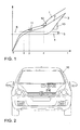
- Fig. 1 is the course of the accelerator pedal angle 1, the course of the target drive torque 2 and the course of the Istantriebsmoments 3 or propulsion torque of a hybrid vehicle, which includes an electric motor and an internal combustion engine to drive over the time t.
- the electric motor is started while the engine is not activated, so that the vehicle runs at the beginning purely electric.
- the driver pushes the accelerator pedal of the vehicle further through, which is represented by the increasing course of the accelerator pedal angle 1.
- the course of the target drive torque 2, which depends on the accelerator pedal angle 1 substantially corresponds to the course of the accelerator pedal angle. 1
- the target drive torque 2 corresponds to the torque 4 that can be supplied by the electric motor.
- the course of the propulsion torque or actual driving torque 3 forms a kind of plateau between times x and z. That is, the actual drive torque 3 remains almost constant, although the driver has pushed the accelerator pedal further.
- the driver recognizes, in other words, that the actual drive torque 3 remains almost constant, even though the driver has pushed the accelerator pedal further, that the vehicle is about to enter the "E-driving" state (ie, the state of purely electric driving) leave because the selected via the accelerator pedal target drive torque is greater than the to be provided by the electric motor drive torque.
- the driver advantageously feels through the plateau that he is at the border of the state "e-driving” and can therefore decide for himself whether he wants to stay in the state "e-driving” or if he wants to leave this state.
- a vehicle 10 according to the invention is shown.
- the vehicle 10 according to the invention comprises a controller 9 according to the invention.
Landscapes
- Engineering & Computer Science (AREA)
- Transportation (AREA)
- Mechanical Engineering (AREA)
- Chemical & Material Sciences (AREA)
- Combustion & Propulsion (AREA)
- Automation & Control Theory (AREA)
- Electric Propulsion And Braking For Vehicles (AREA)
- Hybrid Electric Vehicles (AREA)
Description
- Die vorliegende Erfindung betrifft ein Verfahren, um einen Verbrennungsmotor eines Fahrzeugs (insbesondere eines Hybridfahrzeugs) zum Antrieb des Fahrzeugs zu aktivieren sowie eine entsprechend ausgestaltete Steuerung und ein entsprechend ausgestaltetes Fahrzeug.
- Die
WO 02/26520 A1 - Die
DE 196 37 210 A1 beschreibt eine Antriebsstrangsteuerung, welche abhängig von Stellungen des Fahrpedals und des Bremspedals Antriebsquellen und verzögernde Einheiten steuert. - Die
DE 698 31 468 T2 beschreibt ein Antriebssteuerungssystem, mit welchem ein Ruck verhindert wird, welcher andernfalls erzeugt würde, wenn eine Brennkraftmaschine gestartet wird, während das Fahrzeug durch einen Elektromotor betrieben wird. - Im Stand der Technik wird bei Erreichen des momentan bereitstellbaren Antriebsmoments der Verbrennungsmotor angelassen. Der Fahrer wird über einen Druckpunkt am Gaspedal benachrichtigt, vgl. z.B.
DE 10 2008 000 577 . Es ist ebenfalls bekannt, das Anlassen des Verbrennungsmotors zu verzögern. Die Dauer der Verzögerung hängt von der Gaspedalposition ab, vgl.EP-A-2 206 622 . - Nach dem Stand der Technik wird bei einem Hybridfahrzeug, welches zum Antrieb des Fahrzeugs sowohl einen Elektromotor als auch einen Verbrennungsmotor umfasst, der Verbrennungsmotor gestartet, wenn das von dem Fahrer vorgegebene Sollmoment über demjenigen Moment liegt, welches von dem Elektromotor bereitgestellt werden kann. Da der Fahrer keine Information vorliegen hat, wann das in der Regel über das Fahrpedal vorgegebene Sollmoment größer als das von dem Elektromotor bereitgestellte Moment ist, ist es für den Fahrer schwer, sein Fahrzeug ausschließlich mit dem Elektromotor anzutreiben.
- Daher stellt sich die vorliegende Erfindung die Aufgabe, die Möglichkeit, ein Fahrzeug nur durch den Elektromotor zu betreiben, zumindest zu erleichtern.
- Erfindungsgemäß wird diese Aufgabe durch ein Verfahren zur Aktivierung eines Verbrennungsmotors für ein Fahrzeug nach Anspruch 1, durch eine Steuerung nach Anspruch 9 und durch ein Fahrzeug nach Anspruch 11 gelöst. Die abhängigen Ansprüche definieren bevorzugte und vorteilhafte Ausführungsformen der vorliegenden Erfindung.
- Im Rahmen der vorliegenden Erfindung wird ein Verfahren zur Aktivierung eines Verbrennungsmotors für ein Fahrzeug (insbesondere für ein Hybridfahrzeug) bereitgestellt. Dabei umfasst das Fahrzeug einen Elektromotor und den Verbrennungsmotor, welche beide zum Antrieb des Fahrzeugs ausgestaltet sind. Der Verbrennungsmotor wird automatisch aktiviert, wenn ein beispielsweise über ein Fahrpedal des Fahrzeugs vorgegebenes Sollantriebsmoment größer als eine Momentensumme ist. Dabei setzt sich diese Momentensümme aus einem von dem Elektromotor aktuell bereitstellbaren Antriebsmoment und einem Zusatzmoment, welches größer als 0 ist, zusammen. Unter dem von dem Elektromotor aktuell bereitstellbaren Antriebsmoment wird dabei das Antriebsmoment verstanden, welches zu dem jeweiligen Zeitpunkt maximal von dem Elektromotor zum Antrieb des Fahrzeugs zur Verfügung gestellt werden kann.
- Indem der Verbrennungsmotor nicht bereits dann aktiviert oder gestartet wird, wenn das Sollantriebsmoment größer als das von dem Elektromotor bereitstellbare Antriebsmoment ist, sondern erst dann aktiviert wird, wenn das Sollantriebsmoment um das Zusatzmoment größer als das von dem Elektromotor bereitstellbare Antriebsmoment ist, existiert vorteilhafterweise eine Phase, in welcher der Fahrer beispielsweise mit seinem Fahrpedal das Sollantriebsmoment vergrößert (indem er das Fahrpedal weiter durchgedrückt), in welcher aber das Antriebsmoment des Fahrzeugs nicht erhöht wird, da der Verbrennungsmotor noch nicht aktiviert worden ist. Dadurch kann der Fahrer intuitiv durch entsprechend dosiertes Gasgeben (dosiertes Zustellen des Fahrpedals) den maximal verfügbaren Bereich des Elektromotors intuitiv erfassen, ohne diesen Bereich zu übertreten. Dadurch kann der Fahrer einen Wechsel in den hybridischen Fahrbetrieb (mit Aktivierung des Verbrennungsmotors) vermeiden, wodurch das Erlebnis, rein elektrisch zu fahren (was auch als "E-Fahren" bezeichnet wird) merklich erweitert wird.
- Das Zusatzmoment kann dabei von der aktuellen Geschwindigkeit des Fahrzeugs und/oder von dem von dem Elektromotor aktuell bereitstellbaren Antriebsmoment abhängen.
- Insbesondere ist das Zusatzmoment umso größer, je höher die Geschwindigkeit des Fahrzeugs ist. In ähnlicher Weise ist das Zusatzmoment insbesondere umso größer, je höher das verfügbare oder bereitstellbare Antriebsmoment des Elektromotors ist. Beispielsweise könnte das Zusatzmoment 50 Nm bzw. 20 Nm betragen, wenn das bereitstellbare Antriebsmoment des Elektromotors 100 bzw. 50 Nm beträgt.
- Bei einer hohen Belastung des elektrischen Systems des Fahrzeugs (z. B: bei einem hohen Stromverbrauch der Klimaanlage) und bei damit verbundenen Reduktionsmaßnahmen kann das Zusatzmoment entsprechend verändert werden. Zum Beispiel könnte das Zusatzmoment umso kleiner festgesetzt werden, je größer die Belastung durch das elektrische System des Fahrzeugs ist.
- Gemäß einer bevorzugten erfindungsgemäßen Ausführungsform wird der Verbrennungsmotor nur dann automatisch aktiviert, wenn ein Fahrpedalgradient größer als ein vorbestimmter Schwellenwert ist. Dabei wird unter dem Fahrpedalgradient die Geschwindigkeit verstanden, mit welcher das Fahrpedal des Fahrzeugs niedergedrückt wird.
- Zur Ermittlung der Stellung des Fahrpedal das existieren zwei Möglichkeiten. Entweder entspricht die Stellung des Fahrpedals einem Winkel (dem Fahrpedalwinkel), oder die Stellung des Fahrpedals entspricht einem Abstand (einer Strecke) zwischen dem Fahrpedal und einem definierten Punkt im Fahrzeug. In jedem Fall kann über den Fahrpedalwinkel oder über die entsprechende Strecke das Sollantriebsmoment vorgegeben werden. Der Fahrpedalgradient entspricht in dem einen Fall einer Winkeldifferenz pro Zeiteinheit und im anderen Fall einer Streckendifferenz pro Zeiteinheit.
- Gemäß der bevorzugten erfindungsgemäßen Ausführungsform wird der Verbrennungsmotor dann automatisch aktiviert, wenn zum einen das Sollantriebsmoment größer als die Summe aus dem von dem Elektromotor momentan bereitstellbaren Antriebsmoment und dem Zusatzmoment ist, und wenn gleichzeitig der positive Fahrpedalgradient größer als der vorbestimmte Schwellenwert ist. Durch diese erfindungsgemäße Ausführungsform wird ein vom Fahrer unerwünschter Start des Verbrennungsmotors beispielsweise bei steigender Drehzahl des Elektromotors und einem damit verbundenen Abnehmen des verfügbaren Moments des Elektromotors vermieden.
- Der vorbestimmte Schwellenwert ist dabei insbesondere abhängig von der Geschwindigkeit des Fahrzeugs.
- Durch diese Geschwindigkeitsabhängigkeit des Schwellenwerts soll es zu keiner für den Fahrer unerwarteten oder unbeherrschbaren Fahrzeugreaktion kommen. Daher wird vorteilhafterweise bei einer geringen Geschwindigkeit des Fahrzeugs mit einem kleineren Schwellenwert gearbeitet, da der potentielle Momentenzuwachs nach der Aktivierung des Verbrennungsmotors zu einer größeren Beschleunigung des Fahrzeugs führen würde, als dies bei einer höheren Geschwindigkeit des Fahrzeugs der Fall wäre. Darüber hinaus wird durch die Geschwindigkeitsabhängigkeit des Schwellenwerts verhindert, dass bei Rangiervorgängen (d.h. bei einer geringen Geschwindigkeit) eine nennenswerte Beschleunigung nach der Aktivierung des Verbrennungsmotors erfolgt, da die Aktivierung des Verbrennungsmotors entsprechend früh (z. B. kurz nachdem das Sollantriebsmoment größer als die Summe aus dem verfügbaren Antriebsmoment des Elektromotors und dem Zusatzmoment ist) erfolgt.
- Nach der Aktivierung des Verbrennungsmotors wird das Istantriebsmoment des Fahrzeugs, welches sich nun aus dem von dem Elektromotor bereitgestellten Antriebsmoment und dem von dem Verbrennungsmotor bereitgestellten Antriebsmoment zusammensetzt, insbesondere vergrößert, bis es dem Sollantriebsmoment entspricht. Dazu wird das von dem Verbrennungsmotor und/oder Elektromotor bereitgestellte Antriebsmoment so lange erhöht, bis dieses Istantriebsmoment dem Sollantriebsmoment entspricht. Eine Zeitdauer oder Geschwindigkeit, in/mit welcher diese Überführung durchgeführt wird, bis das Istantriebsmoment dem Sollantriebsmoment entspricht, wird dabei vorteilhafterweise in Abhängigkeit von dem aktuellen Fahrpedalgradienten und/oder von der Geschwindigkeit des Fahrzeugs gewählt.
- Bei der Überführung des Istantriebsmoments in das Sollantriebsmoment steht wiederum die Beherrschbarkeit des Fahrzeugs durch den Fahrer im Vordergrund; beispielsweise sollte keine abrupte Beschleunigung des Fahrzeugs erfolgen. Daher wird die Geschwindigkeit, mit welcher das Istantriebsmoment in das Sollantriebsmoment überführt wird, umso geringer gewählt, je geringer die aktuelle Geschwindigkeit des Fahrzeugs ist. Mit anderen Worten ist der Anstieg des Istantriebsmoments flacher, wenn die Fahrzeuggeschwindigkeit gering ist, und steiler, wenn die Fahrzeuggeschwindigkeit hoch ist. Der Fahrer hat allerdings die Möglichkeit, die Geschwindigkeit der Überführung und damit die Zeitdauer, bis das Istantriebsmoment dem Sollantriebsmoment entspricht, durch den Fahrpedalgradienten zu beeinflussen. Bei einem hohen Fahrpedalgradient (d.h. wenn der Fahrer das Fahrpedal rasch durchgedrückt hat) erfolgt die Überführung des Istantriebsmoments in das Sollantriebsmoment schneller (mit einer höheren Geschwindigkeit oder in einer geringeren Zeitdauer), als wenn der Fahrpedalgradient gering ist (d.h. wenn der Fahrer das Fahrpedal langsam betätigt).
- Vorteilhafterweise wird das erfindungsgemäße Verfahren nur durchgeführt, wenn eine vorbestimmte Betriebsart des Fahrzeugs bzw. ein spezieller Modus der Betriebsstrategie des Fahrzeugs ausgewählt ist. Diese Betriebsart oder dieser spezielle Modus kann beispielsweise durch das Betätigen einer E-Fahrtaste aktiviert werden.
- Im Rahmen der vorliegenden Erfindung wird auch eine Steuerung zur Aktivierung eines Verbrennungsmotors für ein Fahrzeug bereitgestellt. Dabei ist die Steuerung derart ausgestaltet, dass die Steuerung in der Regel über die Stellung des Fahrpedals ein Sollantriebsmoment, von dem Elektromotor ein von diesem aktuell bereitstellbares Antriebsmoment sowie ein vorbestimmtes Zusatzmoment erfasst. Die Steuerung aktiviert den Verbrennungsmotor dann, wenn das erfasste Sollantriebsmoment größer als die Summe aus dem aktuell von dem Elektromotor bereitstellbaren Antriebsmoment und dem Zusatzmoment ist.
- Die Vorteile der erfindungsgemäßen Steuerung entsprechen den Vorteilen des erfindungsgemäßen Verfahrens, welche vorab im Detail ausgeführt sind, so dass hier auf eine Wiederholung verzichtet wird.
- Schließlich wird im Rahmen der vorliegenden Erfindung ein Fahrzeug bereitgestellt, welches einen Verbrennungsmotor, einen Elektromotor und eine erfindungsgemäße Steuerung umfasst.
- Die vorliegende Erfindung ist insbesondere für Hybridfahrzeuge geeignet, welche zum Antrieb des Fahrzeugs sowohl einen Elektromotor als auch einen Verbrennungsmotor umfassen. Selbstverständlich ist die vorliegende Erfindung nicht auf diesen bevorzugten Anwendungsbereich beschränkt, da die vorliegende Erfindung auch bei Schiffen, Flugzeugen sowie gleisgebundenen oder spurgeführten Fahrzeugen einsetzbar ist.
- Im Folgenden wird die vorliegende Erfindung anhand bevorzugter erfindungsgemäßer Ausführungsformen im Detail mit Bezug zu den Figuren beschrieben.
- In Fig. 1
- sind erfindungsgemäße Verläufe des Fahrpedalwinkels, des Sollantriebsmoments und des Istantriebsmoments über der Zeit dargestellt.
- In Fig. 2
- ist schematisch ein erfindungsgemäßes Fahrzeug mit einer erfindungsgemäßen Steuerung dargestellt.
- In
Fig. 1 ist der Verlauf des Fahrpedalwinkels 1, der Verlauf des Sollantriebsmoments 2 und der Verlauf des Istantriebsmoments 3 oder Vortriebsmoments eines Hybridfahrzeugs, welches zum Antrieb einen Elektromotor und einen Verbrennungsmotor umfasst, über der Zeit t dargestellt. Zum Zeitpunkt t=0 wird Elektromotor gestartet, während der Verbrennungsmotor nicht aktiviert ist, so dass das Fahrzeug zu Beginn rein elektrisch fährt. - Um das Fahrzeug zu beschleunigen, drückt der Fahrer das Fahrpedal des Fahrzeugs weiter durch, was durch den ansteigenden Verlauf des Fahrpedalwinkels 1 dargestellt ist. Der Verlauf des Sollantriebsmoments 2, welches von dem Fahrpedalwinkel 1 abhängt, entspricht im Wesentlichen dem Verlauf des Fahrpedalwinkels 1.
- Zum Zeitpunkt t=x entspricht das Sollantriebsmoment 2 dem von dem Elektromotor bereitstellbaren Moment 4. Bei einem Hybridfahrzeug nach dem Stand der Technik würde also zu diesem Zeitpunkt t=x der Verbrennungsmotor gestartet werden. Erfindungsgemäß erfolgt die Aktivierung des Verbrennungsmotors zum Zeitpunkt t=x noch nicht, da der Verbrennungsmotor erst dann gestartet wird, wenn das Sollantriebsmoment 2 größer als die Summe aus dem von dem Elektromotor bereitstellbaren Antriebsmoment 4 und dem Zusatzmoment bzw. Offset 5 ist. Da der Elektromotor ab dem Zeitpunkt t=x nicht mehr in der Lage ist, das Sollantriebsmoment bereitzustellen, trennt sich zum Zeitpunkt t=x der Verlauf des Sollantriebsmoments 2 von dem Verlauf des Istantriebsmoments 3.
- Diese Bedingung, dass das Sollantriebsmoment 2 gleich der Summe aus dem von dem Elektromotor bereitstellaren Antriebsmoment 4 und dem Zusatzmoment 5 ist, ist zum Zeitpunkt t=y erfüllt. Da allerdings zu diesem Zeitpunkt t=y der Fahrpedalgradient 11 unterhalb eines vorbestimmten Schwellenwerts liegt, wird der Verbrennungsmotor noch nicht aktiviert.
- Erst zum Zeitpunkt t=z liegt der Fahrpedalgradient 12 über dem vorbestimmten Schwellenwert. Da zu diesem Zeitpunkt t=z auch das Sollantriebsmoment 2 größer als die Summe aus dem von dem Elektromotor bereitstellbaren Antriebsmoment 4 und dem Zusatzmoment 5 ist, wird zu diesem Zeitpunkt t=z der Verbrennungsmotor gestartet.
- Da sich das Istantriebsmoment 3 ab dem Zeitpunkt t=z durch das Antriebsmoment des Elektromotors und durch das Antriebsmoment des Verbrennungsmotors zusammensetzt, steigt das Istantriebsmoment 3 ab dem Zeitpunkt t=z an. Die Steigung dieses Anstiegs oder der Gradient 13 hängt zum einen von der aktuellen Geschwindigkeit des Fahrzeugs und zum anderen von dem Fahrpedalgradienten 12 zum Zeitpunkt t=z ab.
- Es sei darauf hingewiesen, dass der Verlauf des Vortriebmoments oder Istantriebsmoments 3 zwischen den Zeitpunkten x und z eine Art Plateau ausbildet. D.h. das Istantriebsmoment 3 bleibt nahezu konstant, obwohl der Fahrer das Fahrpedal weiter durchgedrückt hat. Der Fahrer erkennt mit anderen Worten daran, dass das Istantriebsmoment 3 nahezu konstant bleibt, obwohl der Fahrer das Fahrpedal weiter durchgedrückt hat, dass sich das Fahrzeug kurz davor befindet, den Zustand "E-Fahren" (d.h. den Zustand des rein elektrischen Fahrens) zu verlassen, da das über das Fahrpedal gewählte Sollantriebsmoment größer als das von dem Elektromotor bereitzustellende Antriebsmoment ist. Dadurch erhält der Fahrer vorteilhafterweise die Möglichkeit, entweder die Aktivierung des Verbrennungsmotors zu provozieren, indem er das Fahrpedal rasch weiter durchgedrückt und damit den Fahrpedalgradient über den vorbestimmten Schwellenwert anhebt, oder die Aktivierung des Verbrennungsmotors zu vermeiden, indem er beispielsweise das Fahrpedal leicht loslässt und damit das Sollantriebsmoment wieder in einen Bereich bringt, in welchem das Sollantriebsmoment allein von dem Elektromotor geleistet werden kann. Anders ausgedrückt spürt der Fahrer durch das Plateau vorteilhafterweise, dass er sich an der Grenze des Zustands "E-Fahren" befindet und kann daher selbst entscheiden, ob er weiter im Zustand "E-Fahren" bleiben will oder ob er diesen Zustand verlassen will.
- In
Fig. 2 ist schematisch ein erfindungsgemäßes Fahrzeug 10 dargestellt. Neben einem Verbrennungsmotor 7, einem Elektromotor 8 und einem Fahrpedal 14 umfasst das erfindungsgemäße Fahrzeug 10 eine erfindungsgemäße Steuerung 9.
Claims (11)
- Verfahren zur Aktivierung eines Verbrennungsmotors (7) für ein Fahrzeug (10),
wobei das Fahrzeug (10) einen Elektromotor (8) und den Verbrennungsmotor (7) jeweils zum Antrieb des Fahrzeugs (10) umfasst, und
wobei der Verbrennungsmotor (7) automatisch aktiviert wird, wenn ein Sollantriebsmoment (2) größer als eine Summe aus einem von dem Elektromotor (8) momentan bereitstellbaren Antriebsmoment (4) und einem Zusatzmoment (5) ist, wobei das Zusatzmoment größer als Null ist. - Verfahren nach Anspruch 1, dadurch gekennzeichnet, dass das Zusatzmoment (5) von der Geschwindigkeit des Fahrzeugs (10) und/oder von dem von dem Elektromotor (8) aktuell bereitstellbaren Antriebsmoment (4) abhängt.
- Verfahren nach Anspruch 2,
dadurch gekennzeichnet,
dass das Zusatzmoment (5) umso größer ist, je höher die Geschwindigkeit ist, und/oder dass das Zusatzmoment (5) umso kleiner ist, je kleiner das von dem Elektromotor (8) aktuell bereitstellbare Antriebsmoment (4) ist. - Verfahren nach einer der vorhergehenden Ansprüche,
dadurch gekennzeichnet,
dass der Verbrennungsmotor (7) nur automatisch aktiviert wird, wenn ein Fahrpedalgradient (11, 12) größer als ein Schwellenwert ist, und
dass der Fahrpedalgradient (11, 12) einer Geschwindigkeit entspricht, mit welcher ein Fahrpedal (14) des Fahrzeugs (10) bewegt wird. - Verfahren nach Anspruch 4, dadurch gekennzeichnet, dass der Schwellenwert abhängig von der Geschwindigkeit des Fahrzeugs (10) ist.
- Verfahren nach einem der vorhergehenden Ansprüche,
dadurch gekennzeichnet,
dass nach einer Aktivierung des Verbrennungsmotors (7) ein Istantriebsmoment (3), welches sich aus einem von dem Elektromotor (8) bereitgestellten Antriebsmoment und einem von dem Verbrennungsmotor (7) bereitgestellten Antriebsmoment zusammensetzt, vergrößert wird, indem das von dem Verbrennungsmotor (7) bereitgestellte Antriebsmoment erhöht wird, um das Istantriebsmoment (3) in das Sollantriebsmoment (2) zu überführen, und dass eine Zeitdauer, in welcher diese Überführung vollständig durchgeführt wird, abhängig von dem Fahrpedalgradienten (11, 12) und/oder von der Geschwindigkeit des Fahrzeugs (10) gewählt wird. - Verfahren nach Anspruch 6,
dadurch gekennzeichnet,
dass die Zeitdauer umso kürzer gewählt wird, umso größer der Fahrpedalgradient (11, 12) ist, und/oder
dass die Zeitdauer umso kürzer gewählt wird, umso größer die Geschwindigkeit ist. - Verfahren nach einem der vorhergehenden Ansprüche, dadurch gekennzeichnet, dass das Verfahren nur in einer vorbestimmten Betriebsart des Fahrzeugs (10) durchgeführt wird.
- Steuerung zur Aktivierung eines Verbrennungsmotors (7) für ein Fahrzeug (10),
wobei das Fahrzeug (10) einen Elektromotor (8) und den Verbrennungsmotor (7) jeweils zum Antrieb des Fahrzeugs (10) umfasst,
wobei die Steuerung (9) derart ausgestaltet ist, dass die Steuerung (9) ein Sollantriebsmoment (2), ein Zusatzmoment (6) und ein aktuell von dem Elektromotor (8) bereitstellbares Antriebsmoment 4) erfasst, wobei das Zusatzmoment größer als Null ist, und
wobei die Steuerung (9) derart ausgestaltet ist, dass die Steuerung (9) den Verbrennungsmotor (7) aktiviert, wenn das Sollantriebsmoment (2) größer als eine Momentensumme aus dem momentan von dem Elektromotor (8) bereitstellbaren Antriebsmoment (4) und aus dem Zusatzmoment (5) ist. - Steuerung nach Anspruch 9, dadurch gekennzeichnet, dass die Steuerung (9) zur Durchführung des Verfahrens nach einem der Ansprüche 1-8 ausgestaltet ist.
- Fahrzeug mit einem Verbrennungsmotor (7), einem Elektromotor (8) und einer Steuerung (9) nach Anspruch 9 oder 10.
Applications Claiming Priority (2)
| Application Number | Priority Date | Filing Date | Title |
|---|---|---|---|
| DE102011101138A DE102011101138A1 (de) | 2011-05-11 | 2011-05-11 | Verfahren zur Aktivierung eines Verbrennungsmotors für ein Fahrzeug sowie entsprechende Steuerung und Fahrzeug |
| PCT/EP2012/001866 WO2012152400A1 (de) | 2011-05-11 | 2012-04-30 | Verfahren zur aktivierung eines verbrennungsmotors für ein fahrzeug sowie entsprechende steuerung und fahrzeug |
Publications (2)
| Publication Number | Publication Date |
|---|---|
| EP2707265A1 EP2707265A1 (de) | 2014-03-19 |
| EP2707265B1 true EP2707265B1 (de) | 2015-03-11 |
Family
ID=46025611
Family Applications (1)
| Application Number | Title | Priority Date | Filing Date |
|---|---|---|---|
| EP12718085.9A Active EP2707265B1 (de) | 2011-05-11 | 2012-04-30 | Verfahren zur aktivierung eines verbrennungsmotors für ein fahrzeug sowie entsprechende steuerung und fahrzeug |
Country Status (4)
| Country | Link |
|---|---|
| EP (1) | EP2707265B1 (de) |
| CN (1) | CN103547495B (de) |
| DE (1) | DE102011101138A1 (de) |
| WO (1) | WO2012152400A1 (de) |
Families Citing this family (4)
| Publication number | Priority date | Publication date | Assignee | Title |
|---|---|---|---|---|
| DE102015212024B4 (de) * | 2015-06-29 | 2025-10-09 | Robert Bosch Gmbh | Verfahren zur Steuerung und/oder Regelung der Leistung eines Motors |
| DE102019209826A1 (de) * | 2019-07-04 | 2021-01-07 | Audi Ag | Hybridfahrzeugbetrieb in emissionssensitiven Zonen |
| CN112026742B (zh) * | 2019-12-12 | 2021-10-08 | 长城汽车股份有限公司 | 一种发动机控制方法、系统及车辆 |
| DE102024207325A1 (de) * | 2024-08-01 | 2026-02-05 | Volkswagen Aktiengesellschaft | Steuerung für einen Traktionsnetzwandler, Antriebsstrang mit der Steuerung und dem Traktionsnetzwandler für ein Hybridfahrzeug und ein Hybridfahrzeug |
Family Cites Families (17)
| Publication number | Priority date | Publication date | Assignee | Title |
|---|---|---|---|---|
| DE4133059A1 (de) * | 1991-10-04 | 1993-04-08 | Mannesmann Ag | Antriebsanordnung fuer ein kraftfahrzeug |
| DE4422636A1 (de) * | 1994-06-28 | 1996-01-04 | Bayerische Motoren Werke Ag | Verfahren zur automatischen Steuerung einer Brennkraftmaschine in Kraftfahrzeugen mit Hybridantrieb |
| DE19637210B4 (de) | 1996-09-12 | 2007-05-24 | Siemens Ag | Antriebsstrangsteuerung für ein Kraftfahrzeug |
| JP3214427B2 (ja) | 1997-12-12 | 2001-10-02 | トヨタ自動車株式会社 | ハイブリッド車の駆動制御装置 |
| KR100569809B1 (ko) | 2000-09-27 | 2006-04-11 | 지멘스 악티엔게젤샤프트 | 두 개 이상의 파워 유닛 및 기어 박스를 구비한 차량용 동력 전달 계통 제어기 |
| GB2370130B (en) * | 2000-10-11 | 2004-10-06 | Ford Motor Co | A control system for a hybrid electric vehicle |
| US7077223B2 (en) * | 2002-05-29 | 2006-07-18 | Honda Giken Kogyo Kabushiki Kaisha | Hybrid vehicle |
| JP4196958B2 (ja) * | 2005-03-03 | 2008-12-17 | トヨタ自動車株式会社 | ハイブリッド車およびその制御方法 |
| JP4997986B2 (ja) * | 2007-01-19 | 2012-08-15 | トヨタ自動車株式会社 | ハイブリッド車両の制御装置 |
| JP4245069B2 (ja) * | 2007-06-27 | 2009-03-25 | トヨタ自動車株式会社 | 車両用制御装置及び車両駆動制御方法 |
| US7699129B2 (en) * | 2007-10-31 | 2010-04-20 | Ford Global Technologies, Llc | Method and system for alerting a driver that a motive power system is about to be activated |
| JP4479782B2 (ja) * | 2007-11-26 | 2010-06-09 | トヨタ自動車株式会社 | 車両用制御装置 |
| DE102007055740A1 (de) * | 2007-12-10 | 2009-06-18 | Zf Friedrichshafen Ag | Verfahren zum Steuern und/oder Regeln zumindest einer Teillastübernahme bei einer Hybridantriebsanordnung |
| DE102008000577A1 (de) * | 2008-03-10 | 2009-09-17 | Robert Bosch Gmbh | Verfahren und Vorrichtung zum Betreiben eines Fahrzeuges mit Hybridantrieb |
| DE102008029453B4 (de) * | 2008-06-21 | 2021-01-28 | Bayerische Motoren Werke Aktiengesellschaft | Verfahren zum Einstellen eines sog. "Segelmodus" bei einem Kraftfahrzeug |
| DE102009027001A1 (de) * | 2009-06-17 | 2010-12-23 | Robert Bosch Gmbh | Verfahren und Vorrichtung zur Bestimmung des Beginns einer Startphase eines Verbrennungsmotors in einem Hybridfahrzeug |
| DE102009049497A1 (de) * | 2009-10-15 | 2011-04-21 | Daimler Ag | Hybridantriebssteuervorrichtung |
-
2011
- 2011-05-11 DE DE102011101138A patent/DE102011101138A1/de not_active Withdrawn
-
2012
- 2012-04-30 WO PCT/EP2012/001866 patent/WO2012152400A1/de not_active Ceased
- 2012-04-30 EP EP12718085.9A patent/EP2707265B1/de active Active
- 2012-04-30 CN CN201280022491.9A patent/CN103547495B/zh active Active
Also Published As
| Publication number | Publication date |
|---|---|
| EP2707265A1 (de) | 2014-03-19 |
| CN103547495A (zh) | 2014-01-29 |
| DE102011101138A1 (de) | 2012-11-15 |
| CN103547495B (zh) | 2016-05-04 |
| WO2012152400A1 (de) | 2012-11-15 |
Similar Documents
| Publication | Publication Date | Title |
|---|---|---|
| DE102010004846B4 (de) | Verfahren und Steuervorrichtung zur Rekuperation für ein Fahrzeug | |
| DE102010060079B4 (de) | Verfahren und Steuerungssystem zum Öffnen des Antriebsstrangs eines Kraftfahrzeuges | |
| DE102017102412A1 (de) | Systeme und verfahren zum handhaben von drehmoment | |
| DE102011108446B4 (de) | Verfahren und Vorrichtung zur Rekuperation für ein Fahrzeug | |
| EP2768708A1 (de) | Bestimmung einer fahrstrategie für ein fahrzeug | |
| EP1458586A1 (de) | Vorrichtung und verfahren zur regelung der fahrgeschwindigkeit eines fahrzeugs | |
| DE102015206919A1 (de) | Elektro-Kraftfahrzeug und Betriebsverfahren für ein Elektro-Kraftfahrzeug | |
| DE102016207831B4 (de) | Steuersystem | |
| EP2711538A1 (de) | Verfahren und Vorrichtung zum Betrieb einer Start/Stopp-Automatik | |
| DE102014207997B4 (de) | Verfahren und Steuergerät zum Auslegen einer Parksperre unter Zuhilfenahme eines elektrischen Traktionsantriebs | |
| WO2015014614A2 (de) | Verfahren und vorrichtung zur ankupplung eines verbrennungsmotors bei einem verzögerungsvorgang | |
| DE102010062337A1 (de) | Verfahren und Vorrichtung zur Änderung der mechanischen Ankopplung eines Antriebaggregates an einen Triebstrang eines Kraftfahrzeuges, dessen Triebstrang mit mindestens zwei Antriebsaggregaten ausgerüstet ist | |
| EP3564085A1 (de) | Verfahren und system zum einstellen eines fahrbetriebs eines fahrzeugs | |
| EP2358575B1 (de) | Verfahren zum betreiben eines antriebsstrangs | |
| EP3592588B1 (de) | Verfahren zur steuerung eines kraftfahrzeuges und kraftfahrzeug | |
| WO2010007065A1 (de) | Verfahren und vorrichtung zum betrieb eines hybridantriebs eines fahrzeuges | |
| WO2015180886A1 (de) | Verfahren und vorrichtung zur übergabe eines kraftfahrzeugs an den fahrer bei einem automatischen ausparkvorgang | |
| EP3277552B1 (de) | Verfahren zum betreiben einer antriebseinrichtung für ein kraftfahrzeug sowie entsprechende antriebseinrichtung | |
| WO2012152400A1 (de) | Verfahren zur aktivierung eines verbrennungsmotors für ein fahrzeug sowie entsprechende steuerung und fahrzeug | |
| DE102010048548A1 (de) | Verfahren und Vorrichtung zum Betreiben eines Hybridfahrzeugs sowie Computerprogrammprodukt und Fahrzeug | |
| DE102021201276A1 (de) | Verfahren zum Steuern einer elektrischen Maschine zum Antrieb eines Fahrzeugs | |
| DE102013226692A1 (de) | Verfahren und Vorrichtung zum Einstellen der Fahrgeschwindigkeit eines Fahrzeugs | |
| DE102011003447B4 (de) | Verfahren und Vorrichtung zum Steuern des Antriebs eines Hybridelektrofahrzeugs | |
| DE102011085395A1 (de) | Verfahren zum Betreiben eines Kraftfahrzeugs sowie Antriebssystem eines Kraftfahrzeugs | |
| DE102016209714A1 (de) | Zeitliches Strecken eines Anstiegs eines Antriebsmoments bei einem Wechsel der Betriebsart eines Hybridantriebs |
Legal Events
| Date | Code | Title | Description |
|---|---|---|---|
| PUAI | Public reference made under article 153(3) epc to a published international application that has entered the european phase |
Free format text: ORIGINAL CODE: 0009012 |
|
| 17P | Request for examination filed |
Effective date: 20131211 |
|
| AK | Designated contracting states |
Kind code of ref document: A1 Designated state(s): AL AT BE BG CH CY CZ DE DK EE ES FI FR GB GR HR HU IE IS IT LI LT LU LV MC MK MT NL NO PL PT RO RS SE SI SK SM TR |
|
| DAX | Request for extension of the european patent (deleted) | ||
| GRAP | Despatch of communication of intention to grant a patent |
Free format text: ORIGINAL CODE: EPIDOSNIGR1 |
|
| INTG | Intention to grant announced |
Effective date: 20140925 |
|
| GRAS | Grant fee paid |
Free format text: ORIGINAL CODE: EPIDOSNIGR3 |
|
| GRAA | (expected) grant |
Free format text: ORIGINAL CODE: 0009210 |
|
| AK | Designated contracting states |
Kind code of ref document: B1 Designated state(s): AL AT BE BG CH CY CZ DE DK EE ES FI FR GB GR HR HU IE IS IT LI LT LU LV MC MK MT NL NO PL PT RO RS SE SI SK SM TR |
|
| REG | Reference to a national code |
Ref country code: GB Ref legal event code: FG4D Free format text: NOT ENGLISH |
|
| REG | Reference to a national code |
Ref country code: CH Ref legal event code: EP |
|
| REG | Reference to a national code |
Ref country code: IE Ref legal event code: FG4D Free format text: LANGUAGE OF EP DOCUMENT: GERMAN |
|
| REG | Reference to a national code |
Ref country code: AT Ref legal event code: REF Ref document number: 715133 Country of ref document: AT Kind code of ref document: T Effective date: 20150415 |
|
| REG | Reference to a national code |
Ref country code: DE Ref legal event code: R096 Ref document number: 502012002514 Country of ref document: DE Effective date: 20150423 |
|
| REG | Reference to a national code |
Ref country code: NL Ref legal event code: VDEP Effective date: 20150311 |
|
| REG | Reference to a national code |
Ref country code: NL Ref legal event code: VDEP Effective date: 20150311 |
|
| PG25 | Lapsed in a contracting state [announced via postgrant information from national office to epo] |
Ref country code: ES Free format text: LAPSE BECAUSE OF FAILURE TO SUBMIT A TRANSLATION OF THE DESCRIPTION OR TO PAY THE FEE WITHIN THE PRESCRIBED TIME-LIMIT Effective date: 20150311 Ref country code: FI Free format text: LAPSE BECAUSE OF FAILURE TO SUBMIT A TRANSLATION OF THE DESCRIPTION OR TO PAY THE FEE WITHIN THE PRESCRIBED TIME-LIMIT Effective date: 20150311 Ref country code: LT Free format text: LAPSE BECAUSE OF FAILURE TO SUBMIT A TRANSLATION OF THE DESCRIPTION OR TO PAY THE FEE WITHIN THE PRESCRIBED TIME-LIMIT Effective date: 20150311 Ref country code: HR Free format text: LAPSE BECAUSE OF FAILURE TO SUBMIT A TRANSLATION OF THE DESCRIPTION OR TO PAY THE FEE WITHIN THE PRESCRIBED TIME-LIMIT Effective date: 20150311 Ref country code: SE Free format text: LAPSE BECAUSE OF FAILURE TO SUBMIT A TRANSLATION OF THE DESCRIPTION OR TO PAY THE FEE WITHIN THE PRESCRIBED TIME-LIMIT Effective date: 20150311 Ref country code: NO Free format text: LAPSE BECAUSE OF FAILURE TO SUBMIT A TRANSLATION OF THE DESCRIPTION OR TO PAY THE FEE WITHIN THE PRESCRIBED TIME-LIMIT Effective date: 20150611 |
|
| REG | Reference to a national code |
Ref country code: LT Ref legal event code: MG4D |
|
| PG25 | Lapsed in a contracting state [announced via postgrant information from national office to epo] |
Ref country code: GR Free format text: LAPSE BECAUSE OF FAILURE TO SUBMIT A TRANSLATION OF THE DESCRIPTION OR TO PAY THE FEE WITHIN THE PRESCRIBED TIME-LIMIT Effective date: 20150612 Ref country code: LV Free format text: LAPSE BECAUSE OF FAILURE TO SUBMIT A TRANSLATION OF THE DESCRIPTION OR TO PAY THE FEE WITHIN THE PRESCRIBED TIME-LIMIT Effective date: 20150311 Ref country code: RS Free format text: LAPSE BECAUSE OF FAILURE TO SUBMIT A TRANSLATION OF THE DESCRIPTION OR TO PAY THE FEE WITHIN THE PRESCRIBED TIME-LIMIT Effective date: 20150311 |
|
| PG25 | Lapsed in a contracting state [announced via postgrant information from national office to epo] |
Ref country code: NL Free format text: LAPSE BECAUSE OF FAILURE TO SUBMIT A TRANSLATION OF THE DESCRIPTION OR TO PAY THE FEE WITHIN THE PRESCRIBED TIME-LIMIT Effective date: 20150311 |
|
| PG25 | Lapsed in a contracting state [announced via postgrant information from national office to epo] |
Ref country code: RO Free format text: LAPSE BECAUSE OF FAILURE TO SUBMIT A TRANSLATION OF THE DESCRIPTION OR TO PAY THE FEE WITHIN THE PRESCRIBED TIME-LIMIT Effective date: 20150311 Ref country code: PT Free format text: LAPSE BECAUSE OF FAILURE TO SUBMIT A TRANSLATION OF THE DESCRIPTION OR TO PAY THE FEE WITHIN THE PRESCRIBED TIME-LIMIT Effective date: 20150713 Ref country code: CZ Free format text: LAPSE BECAUSE OF FAILURE TO SUBMIT A TRANSLATION OF THE DESCRIPTION OR TO PAY THE FEE WITHIN THE PRESCRIBED TIME-LIMIT Effective date: 20150311 Ref country code: SK Free format text: LAPSE BECAUSE OF FAILURE TO SUBMIT A TRANSLATION OF THE DESCRIPTION OR TO PAY THE FEE WITHIN THE PRESCRIBED TIME-LIMIT Effective date: 20150311 Ref country code: EE Free format text: LAPSE BECAUSE OF FAILURE TO SUBMIT A TRANSLATION OF THE DESCRIPTION OR TO PAY THE FEE WITHIN THE PRESCRIBED TIME-LIMIT Effective date: 20150311 |
|
| PG25 | Lapsed in a contracting state [announced via postgrant information from national office to epo] |
Ref country code: PL Free format text: LAPSE BECAUSE OF FAILURE TO SUBMIT A TRANSLATION OF THE DESCRIPTION OR TO PAY THE FEE WITHIN THE PRESCRIBED TIME-LIMIT Effective date: 20150311 Ref country code: IS Free format text: LAPSE BECAUSE OF FAILURE TO SUBMIT A TRANSLATION OF THE DESCRIPTION OR TO PAY THE FEE WITHIN THE PRESCRIBED TIME-LIMIT Effective date: 20150711 Ref country code: MC Free format text: LAPSE BECAUSE OF FAILURE TO SUBMIT A TRANSLATION OF THE DESCRIPTION OR TO PAY THE FEE WITHIN THE PRESCRIBED TIME-LIMIT Effective date: 20150311 |
|
| REG | Reference to a national code |
Ref country code: CH Ref legal event code: PL |
|
| REG | Reference to a national code |
Ref country code: DE Ref legal event code: R097 Ref document number: 502012002514 Country of ref document: DE |
|
| PG25 | Lapsed in a contracting state [announced via postgrant information from national office to epo] |
Ref country code: IT Free format text: LAPSE BECAUSE OF FAILURE TO SUBMIT A TRANSLATION OF THE DESCRIPTION OR TO PAY THE FEE WITHIN THE PRESCRIBED TIME-LIMIT Effective date: 20150311 |
|
| PLBE | No opposition filed within time limit |
Free format text: ORIGINAL CODE: 0009261 |
|
| STAA | Information on the status of an ep patent application or granted ep patent |
Free format text: STATUS: NO OPPOSITION FILED WITHIN TIME LIMIT |
|
| REG | Reference to a national code |
Ref country code: IE Ref legal event code: MM4A |
|
| PG25 | Lapsed in a contracting state [announced via postgrant information from national office to epo] |
Ref country code: DK Free format text: LAPSE BECAUSE OF FAILURE TO SUBMIT A TRANSLATION OF THE DESCRIPTION OR TO PAY THE FEE WITHIN THE PRESCRIBED TIME-LIMIT Effective date: 20150311 Ref country code: CH Free format text: LAPSE BECAUSE OF NON-PAYMENT OF DUE FEES Effective date: 20150430 Ref country code: LI Free format text: LAPSE BECAUSE OF NON-PAYMENT OF DUE FEES Effective date: 20150430 |
|
| 26N | No opposition filed |
Effective date: 20151214 |
|
| PG25 | Lapsed in a contracting state [announced via postgrant information from national office to epo] |
Ref country code: SI Free format text: LAPSE BECAUSE OF FAILURE TO SUBMIT A TRANSLATION OF THE DESCRIPTION OR TO PAY THE FEE WITHIN THE PRESCRIBED TIME-LIMIT Effective date: 20150311 |
|
| REG | Reference to a national code |
Ref country code: FR Ref legal event code: PLFP Year of fee payment: 5 |
|
| PG25 | Lapsed in a contracting state [announced via postgrant information from national office to epo] |
Ref country code: IE Free format text: LAPSE BECAUSE OF NON-PAYMENT OF DUE FEES Effective date: 20150430 |
|
| PG25 | Lapsed in a contracting state [announced via postgrant information from national office to epo] |
Ref country code: MT Free format text: LAPSE BECAUSE OF FAILURE TO SUBMIT A TRANSLATION OF THE DESCRIPTION OR TO PAY THE FEE WITHIN THE PRESCRIBED TIME-LIMIT Effective date: 20150311 |
|
| REG | Reference to a national code |
Ref country code: FR Ref legal event code: PLFP Year of fee payment: 6 |
|
| PG25 | Lapsed in a contracting state [announced via postgrant information from national office to epo] |
Ref country code: SM Free format text: LAPSE BECAUSE OF FAILURE TO SUBMIT A TRANSLATION OF THE DESCRIPTION OR TO PAY THE FEE WITHIN THE PRESCRIBED TIME-LIMIT Effective date: 20150311 Ref country code: BG Free format text: LAPSE BECAUSE OF FAILURE TO SUBMIT A TRANSLATION OF THE DESCRIPTION OR TO PAY THE FEE WITHIN THE PRESCRIBED TIME-LIMIT Effective date: 20150311 Ref country code: HU Free format text: LAPSE BECAUSE OF FAILURE TO SUBMIT A TRANSLATION OF THE DESCRIPTION OR TO PAY THE FEE WITHIN THE PRESCRIBED TIME-LIMIT; INVALID AB INITIO Effective date: 20120430 |
|
| PG25 | Lapsed in a contracting state [announced via postgrant information from national office to epo] |
Ref country code: CY Free format text: LAPSE BECAUSE OF FAILURE TO SUBMIT A TRANSLATION OF THE DESCRIPTION OR TO PAY THE FEE WITHIN THE PRESCRIBED TIME-LIMIT Effective date: 20150311 |
|
| PG25 | Lapsed in a contracting state [announced via postgrant information from national office to epo] |
Ref country code: BE Free format text: LAPSE BECAUSE OF NON-PAYMENT OF DUE FEES Effective date: 20150430 |
|
| PG25 | Lapsed in a contracting state [announced via postgrant information from national office to epo] |
Ref country code: TR Free format text: LAPSE BECAUSE OF FAILURE TO SUBMIT A TRANSLATION OF THE DESCRIPTION OR TO PAY THE FEE WITHIN THE PRESCRIBED TIME-LIMIT Effective date: 20150311 |
|
| PG25 | Lapsed in a contracting state [announced via postgrant information from national office to epo] |
Ref country code: LU Free format text: LAPSE BECAUSE OF NON-PAYMENT OF DUE FEES Effective date: 20150430 |
|
| REG | Reference to a national code |
Ref country code: FR Ref legal event code: PLFP Year of fee payment: 7 |
|
| REG | Reference to a national code |
Ref country code: AT Ref legal event code: MM01 Ref document number: 715133 Country of ref document: AT Kind code of ref document: T Effective date: 20170430 |
|
| PG25 | Lapsed in a contracting state [announced via postgrant information from national office to epo] |
Ref country code: MK Free format text: LAPSE BECAUSE OF FAILURE TO SUBMIT A TRANSLATION OF THE DESCRIPTION OR TO PAY THE FEE WITHIN THE PRESCRIBED TIME-LIMIT Effective date: 20150311 |
|
| PG25 | Lapsed in a contracting state [announced via postgrant information from national office to epo] |
Ref country code: AT Free format text: LAPSE BECAUSE OF NON-PAYMENT OF DUE FEES Effective date: 20170430 |
|
| PG25 | Lapsed in a contracting state [announced via postgrant information from national office to epo] |
Ref country code: AL Free format text: LAPSE BECAUSE OF FAILURE TO SUBMIT A TRANSLATION OF THE DESCRIPTION OR TO PAY THE FEE WITHIN THE PRESCRIBED TIME-LIMIT Effective date: 20150311 |
|
| RIC2 | Information provided on ipc code assigned after grant |
Ipc: B60W 30/192 20120101ALI20121129BHEP Ipc: B60W 20/00 20160101ALI20121129BHEP Ipc: B60W 50/14 20120101ALI20121129BHEP Ipc: B60W 10/08 20060101ALI20121129BHEP Ipc: B60W 10/06 20060101AFI20121129BHEP Ipc: B60W 30/188 20120101ALI20121129BHEP Ipc: B60K 6/20 20071001ALI20121129BHEP |
|
| P01 | Opt-out of the competence of the unified patent court (upc) registered |
Effective date: 20230523 |
|
| PGFP | Annual fee paid to national office [announced via postgrant information from national office to epo] |
Ref country code: DE Payment date: 20250430 Year of fee payment: 14 |
|
| PGFP | Annual fee paid to national office [announced via postgrant information from national office to epo] |
Ref country code: GB Payment date: 20250422 Year of fee payment: 14 |
|
| PGFP | Annual fee paid to national office [announced via postgrant information from national office to epo] |
Ref country code: FR Payment date: 20250424 Year of fee payment: 14 |