EP2706647A2 - Power supply device - Google Patents
Power supply device Download PDFInfo
- Publication number
- EP2706647A2 EP2706647A2 EP20130020085 EP13020085A EP2706647A2 EP 2706647 A2 EP2706647 A2 EP 2706647A2 EP 20130020085 EP20130020085 EP 20130020085 EP 13020085 A EP13020085 A EP 13020085A EP 2706647 A2 EP2706647 A2 EP 2706647A2
- Authority
- EP
- European Patent Office
- Prior art keywords
- primary battery
- state
- voltage
- power
- storage device
- Prior art date
- Legal status (The legal status is an assumption and is not a legal conclusion. Google has not performed a legal analysis and makes no representation as to the accuracy of the status listed.)
- Withdrawn
Links
Images


Classifications
-
- H—ELECTRICITY
- H02—GENERATION; CONVERSION OR DISTRIBUTION OF ELECTRIC POWER
- H02J—CIRCUIT ARRANGEMENTS OR SYSTEMS FOR SUPPLYING OR DISTRIBUTING ELECTRIC POWER; SYSTEMS FOR STORING ELECTRIC ENERGY
- H02J9/00—Circuit arrangements for emergency or stand-by power supply, e.g. for emergency lighting
- H02J9/04—Circuit arrangements for emergency or stand-by power supply, e.g. for emergency lighting in which the distribution system is disconnected from the normal source and connected to a standby source
- H02J9/06—Circuit arrangements for emergency or stand-by power supply, e.g. for emergency lighting in which the distribution system is disconnected from the normal source and connected to a standby source with automatic change-over, e.g. UPS systems
- H02J9/061—Circuit arrangements for emergency or stand-by power supply, e.g. for emergency lighting in which the distribution system is disconnected from the normal source and connected to a standby source with automatic change-over, e.g. UPS systems for DC powered loads
-
- H—ELECTRICITY
- H02—GENERATION; CONVERSION OR DISTRIBUTION OF ELECTRIC POWER
- H02J—CIRCUIT ARRANGEMENTS OR SYSTEMS FOR SUPPLYING OR DISTRIBUTING ELECTRIC POWER; SYSTEMS FOR STORING ELECTRIC ENERGY
- H02J7/00—Circuit arrangements for charging or depolarising batteries or for supplying loads from batteries
- H02J7/34—Parallel operation in networks using both storage and other dc sources, e.g. providing buffering
-
- G—PHYSICS
- G01—MEASURING; TESTING
- G01R—MEASURING ELECTRIC VARIABLES; MEASURING MAGNETIC VARIABLES
- G01R31/00—Arrangements for testing electric properties; Arrangements for locating electric faults; Arrangements for electrical testing characterised by what is being tested not provided for elsewhere
- G01R31/36—Arrangements for testing, measuring or monitoring the electrical condition of accumulators or electric batteries, e.g. capacity or state of charge [SoC]
- G01R31/382—Arrangements for monitoring battery or accumulator variables, e.g. SoC
- G01R31/3835—Arrangements for monitoring battery or accumulator variables, e.g. SoC involving only voltage measurements
-
- H—ELECTRICITY
- H01—ELECTRIC ELEMENTS
- H01M—PROCESSES OR MEANS, e.g. BATTERIES, FOR THE DIRECT CONVERSION OF CHEMICAL ENERGY INTO ELECTRICAL ENERGY
- H01M12/00—Hybrid cells; Manufacture thereof
- H01M12/04—Hybrid cells; Manufacture thereof composed of a half-cell of the fuel-cell type and of a half-cell of the primary-cell type
- H01M12/06—Hybrid cells; Manufacture thereof composed of a half-cell of the fuel-cell type and of a half-cell of the primary-cell type with one metallic and one gaseous electrode
-
- Y—GENERAL TAGGING OF NEW TECHNOLOGICAL DEVELOPMENTS; GENERAL TAGGING OF CROSS-SECTIONAL TECHNOLOGIES SPANNING OVER SEVERAL SECTIONS OF THE IPC; TECHNICAL SUBJECTS COVERED BY FORMER USPC CROSS-REFERENCE ART COLLECTIONS [XRACs] AND DIGESTS
- Y02—TECHNOLOGIES OR APPLICATIONS FOR MITIGATION OR ADAPTATION AGAINST CLIMATE CHANGE
- Y02E—REDUCTION OF GREENHOUSE GAS [GHG] EMISSIONS, RELATED TO ENERGY GENERATION, TRANSMISSION OR DISTRIBUTION
- Y02E60/00—Enabling technologies; Technologies with a potential or indirect contribution to GHG emissions mitigation
- Y02E60/10—Energy storage using batteries
Definitions
- the present invention relates to a power supply device which can supply an electric power to an electric load even if power supply is stopped from a commercial power source.
- PTL 1 discloses the backup power source which supplies a receiver with the sum of electrical energies from at least two or more dry-cell battery systems when a commercial power source is not available.
- the secondary battery When a secondary battery such as a lead storage battery is used as a backup power source, the secondary battery is maintained in a fully charged state for a certain period when an electric power is normally supplied from a commercial power source. If the secondary battery is maintained in the fully charged state, even for a certain period when the secondary battery is not in use, the electric power is unnecessarily consumed due to self-discharge. Furthermore, if the secondary battery is maintained in the fully charged state, the secondary battery continues to deteriorate. Thus, it is necessary to replace the secondary battery routinely.
- the remaining amount of the dry battery may be decreased due to the self-discharge. If the remaining amount of the dry battery is decreased, a disadvantageous situation may be encountered in that the dry battery cannot operate for an initial targeted operation time. In order to guarantee the rated operation time, it is necessary to replace the dry battery routinely. There is a need for providing a power supply device which can decrease unnecessary power consumption caused by self-discharge of the secondary battery.
- a power supply device including an input terminal to which an electric power is supplied from a commercial power source; an output terminal connected to an electric load; a power storage device to be charged by the electric power supplied from the input terminal and supplying the electric power to the output terminal; a primary battery; and a controller supplying an output of the primary battery to the output terminal, when monitoring a voltage of the commercial power source, which is applied to the input terminal, and a charged state of the power storage device, and detecting that the voltage of the commercial power source falls to a specified voltage value or less and the charged state of the power storage device indicates a specified value or less.
- the primary battery is arranged in addition to the power storage device.
- capacity of the power storage device can be decreased. Since the capacity of the power storage device is decreased, even if the power storage device is maintained in a fully charged state, power consumption caused by self-discharge is decreased. Accordingly, it is possible to reduce unnecessary power consumption.
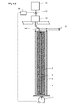
- Fig. 1 illustrates a block diagram of a power supply device according to Embodiment 1.
- An AC power is supplied from a commercial power source 12 to an input terminal 10.
- An electric load 13 is connected to an output terminal 11.
- the electric load 13 is, for example, a transceiver of a radio base station on a mobile communication network.
- An AC-DC converter 20 converts the AC power input to the input terminal 10 to a DC power.
- the DC power is output to the output terminal 11 via an electric power transmission circuit 21, and is supplied to a power storage device 25 via the electric power transmission circuit 21 and a switching element 26. This allows the power storage device 25 to be maintained in a fully charged state at all times.
- a lead storage battery, a lithium ion secondary battery or a lithium ion capacitor may be used.
- Multiple primary batteries 30 are connected to the electric power transmission circuit 21 via respectively associated switching elements 31.
- a metal-air battery for example, such as a zinc air battery, an aluminum air battery and a magnesium air battery may be used.
- Each of the primary batteries 30 includes a positive electrode current collector 32, a negative electrode current collector 33, a negative electrode active material 34 and an electrolytic solution 35.
- the electrolytic solution 35 is separated from the negative electrode active material 34.
- a state where the electrolytic solution 35 is separated from the negative electrode active material 34 is referred to as a "standby state”. If the electrolytic solution 35 is brought into contact with the negative electrode active material 34, an electromotive force is generated. A state where the electrolytic solution 35 comes into contact with the negative electrode active material 34 and the electromotive force is generated is referred to as an "operation state".
- Measurement values of a voltage applied to the input terminal 10, a voltage across terminals of the power storage device 25, and a voltage across terminals of each of the multiple primary batteries 30 are input to a controller 40. Based on the input measurement values of the voltages, the controller 40 performs an on-off control of switching elements 26 and 31, and a switching control from the standby state to the operation state of the primary batteries 30.
- Fig. 2 illustrates a cross-sectional view of the primary battery 30 (refer to Fig. 1 ) which is used in the power supply device according to Embodiment 1.
- the inside of a pouch-shaped separator 36 is filled with the negative electrode current collector 33 and the negative electrode active material 34.
- the negative electrode active material 34 for example, metal particles made of metallic zinc, metallic aluminum and metallic magnesium may be used.
- the negative electrode current collector 33 for example, a metal plate made of nickel may be used.
- the separator 36 for example, a porous membrane made of polyethylene or polypropylene, nonwoven fabric made of resin, or nonwoven fabric made of glass fiber is used.
- the positive electrode current collector 32 adheres to an outer side surface of the separator 36.
- the positive electrode current collector 32 has a structure where a conductive material such as carbon black is coated on a base such as carbon cloth, carbon paper or the like.
- the conductive material includes a catalyst and an adhesive.
- the catalyst for example, manganese dioxide may be used.
- the adhesive for example, polyvinylidene fluoride may be used.
- the positive electrode current collector 32 has multiple fine apertures allowing oxygen to pass therethrough. The oxygen in the atmosphere acts as a positive electrode active material.
- the negative electrode current collector 33 and the positive electrode current collector 32 are connected to the output terminals 37 of the primary battery 30.
- a solvent is accumulated inside the reservoir tank 51.
- the reservoir tank 51 is connected to an electrolyte containing chamber 53 via an on-off valve 52. Crystals of electrolyte are contained inside the electrolyte containing chamber 53.
- the on-off valve 52 is controlled by the controller 40. If the on-off valve 52 is turned on, the solvent inside the reservoir tank 51 is injected into the electrolyte containing chamber 53. The crystals of the electrolyte contained inside the electrolyte containing chamber 53 are dissolved in the solvent to generate the electrolytic solution. The generated electrolytic solution is injected to a space inside the separator 36 through an electrolytic solution injection port 50 provided on the separator 36.
- water may be used for the solvent, and potassium hydroxide (KOH) may be used for the electrolyte.
- KOH potassium hydroxide
- aqueous potassium hydroxide solution is injected into the separator 36, as the electrolyte.
- the electrolytic solution may be contained in the reservoir tank 51 to omit the electrolyte containing chamber 53.
- the electrolytic solution is injected into the separator 36, zinc (Zn) of the negative electrode active material 34 and hydroxide ions (OH - ) in the electrolytic solution react to generate tetra hydroxonium zincate (Zn(OH) 4 2- ) and electrons.
- the tetra hydroxonium zincate is decomposed to generate zinc oxide (ZnO), hydroxide ions and the water.
- the generated electrons are collected in the negative electrode current collector 33. If the electric load is connected across the output terminals 37, the electrons collected in the negative electrode current collector 33 are supplied to the positive electrode current collector 32 through the electric load.
- the hydroxide ions are transported through the separator 36 to reach the negative electrode active material 34.
- the negative electrode active material 34 is oxidized, and the metal oxide, for example zinc oxide, is accumulated.
- Fig. 3 illustrates an equivalent circuit diagram of the power supply device according to Embodiment 1.
- a voltmeter 24 measures the voltage of the commercial power source 12 (refer to Fig. 1 ), which is applied to the input terminal 10. The measured result of the voltmeter 24 is input to the controller 40.
- the controller 40 monitors a measurement value of the voltmeter 24 (voltage of the commercial power source 12, which is applied to the input terminal 10).
- the controller 40 compares the measurement value of the voltmeter 24 with a specified voltage value, and determines that normal power supply from the commercial power source 12 (refer to Fig. 1 ) is stopped, if the measurement value of the voltmeter 24 falls to the specified voltage value or less.
- the electric power transmission circuit 21 includes a bus line 22 and diodes 23. Input and output terminals of the power storage device 25 are connected to the bus line 22 via the switching element 26. A voltmeter 27 measures the voltage across the input and output terminals of the power storage device 25. The measured result of the voltmeter 27 is input to the controller 40. As long as there is no special circumstance, the switching element 26 is switched on at all times. Therefore, the voltage measured by the voltmeter 27 is equal to the voltage applied to the bus line 22.
- the multiple primary batteries 30 are connected to the bus line 22 so as to be in parallel with one another via the respectively associated switching elements 31, and so as to be in parallel with the power storage device 25.
- the diode 23 is arranged for each of primary batteries 30, and is connected to the primary battery 30 in series. The diode 23 is connected such that the direction of the discharging current from the primary battery 30 corresponds to the forward direction. For this reason, a charged current is prohibited from flowing into the primary battery 30.
- a control for preventing the inflow of the charged current may be performed by switching off the switching element 31. In a case of performing this control, the diodes 23 may be omitted.
- Multiple voltmeters 38 measure the voltages across the output terminals of the respective primary batteries 30. The measured result is input to the controller 40.
- a switch 30A indicated within a dashed line illustrating the primary battery 30 represents that the primary battery 30 has two states of the standby state and the operation state. The off-state and the on-state of the switch 30A respectively correspond to the standby state and the operation state.
- the power storage device 25 outputs a required voltage by connecting the lead storage batteries to one another in series, the number of which corresponds to the required voltage for the electric load 13.
- the primary battery 30 has a configuration where multiple zinc-air batteries are connected to one another in series such that an open circuit voltage thereof is slightly higher than the open circuit voltage of the power storage device 25.
- the distance from the output terminal 11 to a position on the bus line 22 to which each of the multiple primary batteries 30 is connected is shorter than the distance from the output terminal 11 to a position on the bus line 22 to which the power storage device 25 is connected.
- Fig. 4 illustrates an example of time changes in the voltage of the bus line 22 (refer to Fig. 3 ) and the voltages across the terminals of the primary battery 30 (refer to Fig. 1 ).
- a solid line of a voltage v1 in the upper row represents the voltage of the bus line 22 (refer to Fig. 3 )
- a solid line of a voltage v2 in the middle row represents the voltage across the terminals of the primary battery 30 (refer to Fig.
- a solid line of a voltage v3 in the lower row represents the voltage across the terminals of the primary battery 30 (refer to Fig. 1 ) to be secondly operated. Since the switching element 26 (refer to Fig. 3 ) is the on-state at all times, the voltage v1 of the bus line 22 can be measured by the voltmeter 27 (refer to Fig. 3 ).
- the power supply from the commercial power source 12 (refer to Fig. 1 ) is assumed to be stopped.
- the measurement value of the voltmeter 24 (refer to Fig. 3 ) falls to a specified voltage value or less. Accordingly, the controller 40 detects that the power supply is stopped from the commercial power source 12.
- the discharge from the power storage device 25 is started, and the electric power is supplied to the electric load 13 via the electric power transmission circuit 21.
- the voltage v1 across the terminals of the power storage device 25 is lowered with the lapse of time by electric discharge of the power storage device 25.
- the voltage v1 of the bus line 22 (refer to Fig. 3 ) is lowered to a voltage threshold value Va. If the controller 40 (refer to Fig. 1 ) detects that the voltage v1 of the bus line 22 (refer to Fig. 3 ) is lowered to the voltage threshold value Va, the controller 40 turns on the on-off valve 52 (refer to Fig. 2 ) of the primary battery 30 to be firstly operated. The electrolytic solution is injected to the primary battery 30, and the voltage v2 across the terminals of the primary battery 30 starts to rise.
- the voltage across the terminals of the power storage device 25 corresponds to a state of charge (SOC) of the power storage device 25. Accordingly, monitoring the voltage v1 of the bus line 22 (refer to Fig. 3 ) is substantially equivalent to monitoring the SOC of the power storage device 25.
- the voltage v2 across the terminals of the primary battery 30 to which the electrolytic solution is injected reaches a rated open circuit voltage Vb.
- the controller 40 detects that the voltage v2 across the terminals reaches the rated open circuit voltage Vb
- the switching element 31 (refer to Fig. 1 ) connected to the primary battery 30 to which the electrolytic solution is injected is switched on.
- the primary battery 30 changes from the standby state to the operation state.
- the discharged current starts to flow from the primary battery 30, and thus the voltage v1 of the bus line 22 (refer to Fig. 3 ) rises. Since voltage drop ⁇ Vb occurs due to the internal resistance of the primary battery 30, the voltage v1 of the bus line 22 (refer to Fig. 3 ) rises to Vb- ⁇ Vb.
- the electric power is supplied from the primary battery 30 in the operation state to the electric load 13.
- the voltage v1 of the bus line 22 (refer to Fig. 3 ) is higher than the open circuit voltage across the terminals of the power storage device 25, that is, if the potential of the bus line 22 (refer to Fig. 3 ) is higher than the potential of the positive electrode of the power storage device 25, the power storage device 25 is charged by using the discharge power from the primary battery 30 in the operation state.
- the power consumption increases in the electric load 13
- the discharge current increases in the primary battery 30.
- the voltage drop due to the internal resistance of the primary battery 30 increases, and thus the voltage v1 of the bus line 22 is lowered.
- the power storage device 25 discharges the electricity. Therefore, the electric power is supplied to the electric load 13 from both of the primary battery 30 and the power storage device 25.
- the charging and discharging of the power storage device 25 are performed according to the power consumption of the electric load 13. As a whole, the voltage v1 of the bus line 22 is lowered with the lapse of time. A sudden change in the power consumption, which is caused by the electric load 13, also switches between charging and discharging of the power storage device 25.
- the controller 40 (refer to Fig. 1 ) starts to inject the electrolytic solution to the primary battery 30 to be secondly operated. Accordingly, the voltage v3 across the terminals of the primary battery 30 secondly operated rises.
- the controller 40 (refer to Fig. 1 ) switches on the switching element 31 (refer to Fig. 1 ) connected to the primary battery 30 to be secondly operated, and switches off the switching element 31 (refer to Fig. 1 ) connected to the primary battery 30 firstly operated. Since the discharge current from the primary battery 30 firstly operated no longer flows, the voltage v2 across the terminals of the primary battery 30 maintains a substantially constant value.
- the primary battery 30 secondly operated discharges electricity.
- the charging and discharging of the power storage device 25 are performed according to the power consumption of the electric load 13.
- the injecting the electrolytic solution to the primary battery 30 to be subsequently operated is started. This enables the electric power to be successively supplied to the electric load 13.
- Embodiment 1 during the period of the standby state of the primary battery 30 (refer to Fig. 1 ), the negative electrode active material 34 (refer to Fig. 2 ) and the electrolytic solution are not in contact with each other. Therefore, it is possible to prevent self-discharge and the deterioration of the battery.
- the electric power is supplied from the power storage device 25 to the electric load 13. Therefore, the power supply is continuously guaranteed.
- the controller 40 monitors the voltage of the commercial power source, which is applied to the input terminal 10, and the SOC of the power storage device 25, and based on the monitored result, supplies the output terminal 11 with the output of at least one primary battery out of the multiple primary batteries 30. More specifically, the controller 40 supplies the output terminal 11 with the output of at least one primary battery out of the multiple primary batteries 30, using detection of at least one event as a trigger, between the event that the voltage of the commercial power source, which is applied to the input terminal 10, falls to the specified voltage value or less and the event that the SOC of the power storage device 25 falls to the preset specified value or less.
- the capacity of the power storage device 25 it is only necessary to set the capacity of the power storage device 25 to such a degree that the electric power can be supplied to the electric load 13 during the period until the primary battery 30 starts to be operated. Therefore, compared to a case of the backup using only the power storage device 25, it is possible to further decrease the capacity thereof. If the capacity of the power storage device 25 is decreased, the power consumption caused by the self-discharge of the power storage device 25 is decreased. Therefore, even if the power storage device 25 maintains the fully charged state, it is possible to reduce a power loss caused by the self-discharge.
- Embodiment 1 as a trigger for operating the primary battery 30 (refer to Fig. 1 ), adopts the monitored result (voltage v1 in Fig. 4 ) of the SOC of the power storage device 25 (refer to Fig. 1 ).
- the monitored result of the voltage of the commercial power source, which is applied to the input terminal 10 may be adopted.
- the on-off valve 52 (refer to Fig. 2 ) of the primary battery 30 to be firstly operated may be turned on after a lapse of the preset time for standby from when the controller 40 detects that the voltage of the commercial power source, which is applied to the input terminal 10, falls to the specified voltage value or less.
- the time for standby is determined based on the available time for the power storage device 25 to supply the sufficient electric power to the electric load 13 (refer to Fig. 1 ).
- both of the monitored result of the SOC of the power storage device 25 (refer to Fig. 1 ) and the monitored result of the voltage of the commercial power source, which is applied to the input terminal 10, may be adopted.
- Fig. 9 illustrates an example of a flowchart in a process performed by the controller 40 in a case where both of the monitored result of the SOC of the power storage device 25 and the monitored result of the voltage of the commercial power source, which is applied to the input terminal 10, are adopted as the trigger for operating the primary battery 30.
- the process in this flowchart starts from when the controller 40 detects that the voltage of the commercial power source falls to the specified voltage value or less.
- Step ST1 a standby time decision counter is initialized in Step ST1.
- the initialized counter is decremented with the lapse of time and becomes zero when the time for standby elapses.
- Step ST2 it is determined whether or not predetermined time for standby has elapsed. Specifically, it is determined whether or not the standby time decision counter has been decremented to become zero. If the predetermined time for standby has not yet elapsed, it is determined whether the SOC of the power storage device 25 (refer to Fig. 1 ) is equal to or less than the specified value in Step ST3.
- Step ST 4 it is determined whether or not the voltage of the commercial power source has been restored to have the specified voltage value. If the voltage of the commercial power source has been restored, the process ends. If the voltage of the commercial power source has not yet been restored, the process returns to Step ST2.
- Step ST2 if it is determined that the predetermined time for standby has elapsed, or in Step ST3, if it is determined that the SOC of the power storage device 25 is equal to or less than the specified value (corresponding to time t1 and t3 in Fig. 4 ), in Step ST5, it is determined whether or not the standby primary battery 30 still remains. If the standby primary battery 30 does not remain, the process ends. If the standby primary battery 30 still remains, in Step ST6, the standby primary battery 30 is started to be operated.
- Step ST6 is the same as the process from the time t1 to t2 in Fig. 4 . That is, the on-off valve 52 (refer to Fig. 2 ) of the primary battery 30 to be operated is turned on. If the open circuit voltage of the primary battery 30 rises up to the rated voltage value, the switching element 31 is switched on.
- Step ST7 the standby time decision counter is initialized, and the decrement process of the counter resumes.
- the process returns to Step ST2.
- the initial value of the time for standby set in Step ST1 is not always the same as the initial value of the time for standby set in Step ST7.
- the initial value of the time for standby set in Step ST1 may be set to such a value that the fully charged power storage device 25 can supply the sufficient electric power to the electric load 13 (refer to Fig. 1 ).
- the initial value of the time for standby set in Step ST7 may be set to such a value that the primary battery 30 can supply the sufficient electric power to the electric load 13 (refer to Fig. 1 ).
- Fig. 10 illustrates an example of time changes in the voltage of the bus line 22 (refer to Fig. 3 ) and the voltage across the terminals of the primary battery 30 (refer to Fig. 1 ).
- the primary battery 30 is changed to the operation state by turning on the on-off valve 52 (refer to Fig. 2 ) of the primary battery to be firstly operated.
- this process allows the voltage v2 across the terminals of the primary battery 30 to be firstly operated to start to rise.
- there is a certain abnormality in the primary battery 30 as compared to the case in Fig.
- the rising rate of the voltage v2 across the terminals is slow.
- the primary battery 30 corresponding to the on-off valve 52 (refer to Fig. 2 ) that is turned on is changed to the operation state for enabling the output of the electric power. Even if a certain abnormality causes the electrolytic solution not to be injected to a space containing the negative electrode active material 34, and thus the electromotive force is not generated, the state of the primary battery 30 corresponding to the on-off valve 52 opened is referred to as the "operation state".
- the controller 40 monitors whether the operation of the operated primary battery 30 is good or poor.
- the controller 40 when detecting that at the time t5 when the monitoring time tr has elapsed from the time t1, the voltage v2 across the terminals does not reach the rated open circuit voltage Vb, determines that the primary battery 30 is poorly operated. If the operated primary battery 30 is determined to be poorly operated, the controller 40 turns on the on-off valve 52 (refer to Fig. 2 ) of the primary battery 30 to be subsequently operated.
- the voltage v3 across the terminals of the primary battery 30 to be subsequently operated starts to rise.
- the voltage v3 across the terminals reaches the rated open circuit voltage Vb.
- the controller 40 when detecting that the voltage v3 across the terminals has reached the rated open circuit voltage Vb, switches on the switching element 31 (refer to Fig. 1 ) connected to the primary battery 30 which has reached the rated open circuit voltage Vb.
- the voltage v3 across the terminals of the primary battery 30 is lowered by the voltage drop ⁇ Vb caused by the internal resistance.
- the voltage v1 of the bus line 22 (refer to Fig. 3 ) is lowered to a voltage Vc which is lower than the voltage threshold value Va, during the time until time 6.
- the switching element 31 of the operated primary battery 30 is switched on, the voltage v1 of the bus line 22 is restored to Vb- ⁇ Vb.
- the electric power is supplied from the secondly operated primary battery 30 to the electric load 13 (refer to Fig. 1 ). If the voltage v1 of the bus line 22 is lowered to the voltage threshold value Va, the controller 40 turns on the on-off valve 52 (refer to Fig. 2 ) of the primary battery 30 to be subsequently operated.
- Fig. 11 illustrates a block diagram during a backup operation of the power supply device according to a modification example of Embodiment 1.
- Embodiment 1 illustrated in Figs. 1 to 9 as illustrated in Fig. 6 , when the power supply is stopped from the commercial power source 12, the states of the primary batteries 30 are changed to the operation states sequentially and one by one.
- the states of multiple primary batteries 30 are simultaneously changed to the operation state.
- Fig. 11 illustrates an example where two primary batteries 30 are simultaneously left in the operation state.
- the number of the primary batteries 30 to be simultaneously operated is decided depending on the electric power required by the electric load 13. It is possible to supply the sufficient electric power to the electric load 13 by simultaneously operating the multiple primary batteries 30.
- the number of the primary batteries 30 to be simultaneously operated is stored in a storage device 41 inside the controller 40.
- the electric power required by the electric load 13 varies for each radio base station, for example.
- the power supply device according to the modification example can set a value which is to be stored in the storage device 41 for each radio base station. Accordingly, the power supply device can be applied to various scales of the radio base station.
- the controller 40 When simultaneously operating the multiple primary batteries 30, the controller 40 independently monitors each voltage across the terminals of the operated primary batteries 30. When determining that at least one primary battery 30 out of the operated primary batteries 30 is poorly operated, the controller 40 changes the states of the same number of the other primary batteries 30 as the number of the primary batteries 30 determined to be poorly operated, to the operation states. This can suppress the voltage v1 of the bus line 22 (refer to Fig. 3 ) from being excessively lowered.
- Fig. 12 illustrates a schematic diagram of a primary battery according to Embodiment 2.
- a gravimeter 55 measures weights of the positive electrode current collector 32, the negative electrode current collector 33, the negative electrode active material 34 and the separator 36. Since the reservoir tank 51, the on-off valve 52 and the electrolyte containing chamber 53 are fixed to a base, the weights thereof are not measured by the gravimeter 55. The measured result is input to the controller 40. If the electrolytic solution is injected into the separator 36, the weights measured by the gravimeter 55 are increased. It is possible to estimate an injection amount of the electrolytic solution by checking the increase in weight.
- the controller 40 stores a tendency of the increase in weight when the electrolytic solution is normally injected into the separator 36. By comparing the tendency of the increase in the weight measured by the gravimeter 55 with the tendency of the increase in the normal weight stored in advance, it is possible to detect whether or not the injection of the electrolytic solution is normally performed.
- the controller 40 monitors the result measured by the gravimeter 55 after the time t1 illustrated in Fig. 10 . When the tendency of the increase in the weight measured by the gravimeter 55 departs from a normal range, the controller 40 determines that the electrolytic solution is not normally injected into the separator 36.
- a current meter 56 may be inserted to an injection route of the electrolytic solution.
- the measured result of the current meter 56 is input to the controller 40.
- Embodiment 1 As described above, by monitoring an injection state of the electrolytic solution using the gravimeter 55, the current meter 56 or the like, it is possible to determine whether the operation of the operated primary battery 30 is good or poor.
- the determination method adopted in Embodiment 1, as to whether the operation is good or poor, based on the voltage across the terminals of the primary battery 30 may be used in conjunction with the determination method adopted in Embodiment 2, as to whether the operation is good or poor, based on the injection state of the electrolytic solution.
- Embodiment 3 The block diagram of the power supply device according to Embodiment 3 is the same as the block diagram of the power supply device according to Embodiment 1 illustrated in Fig. 1 .
- the power storage device 25 maintains the fully charge state for the period when the electric power is supplied from the commercial power source 12, but it is not necessarily to maintain the fully charged state.
- the power storage device 25 may store an electrical energy required during a period until the primary battery 30 starts to be operated when a power failure occurs.
- Embodiment 1 as the power storage device 25, a small capacity device is adopted, which can store the electrical energy required during the period until the primary battery 30 starts to be operated when the power failure occurs.
- the power storage device 25 adopted to Embodiment 3 has a larger capacity than the capacity of the power storage device 25 adopted to Embodiment 1. Therefore, without a need to maintain the fully charged state of the power storage device 25, it is possible to store the sufficient electrical energy.
- the controller 40 monitors the state of charge (SOC) of the power storage device 25, and charges the power storage device 25 by switching on the switching element 26, if the state of charge is lower than a reference value. If the state of charge is restored to the reference value or more, the controller 40 switches off the switching element 26. In this manner, the controller 40 controls the charging of the power storage device 25 so as to maintain the state of charge required for the backup.
- SOC state of charge
- Embodiment 3 the power storage device 25 which has the larger capacity than the storage device 25 in Embodiment 1 is adopted. However, similarly to Embodiment 1, it is possible to reduce the power consumption caused by the self-discharge by not fully charging the power storage device 25.
Landscapes
- Engineering & Computer Science (AREA)
- Power Engineering (AREA)
- Business, Economics & Management (AREA)
- Emergency Management (AREA)
- Charge And Discharge Circuits For Batteries Or The Like (AREA)
- Secondary Cells (AREA)
- Stand-By Power Supply Arrangements (AREA)
Abstract
Description
- The present invention relates to a power supply device which can supply an electric power to an electric load even if power supply is stopped from a commercial power source.
- As a backup power source during a power failure, a secondary battery such as a lead storage battery has been used. In addition, PTL 1 discloses the backup power source which supplies a receiver with the sum of electrical energies from at least two or more dry-cell battery systems when a commercial power source is not available.
-
- [PTL 1] Japanese Unexamined Patent Application Publication No.
2007-189813 - When a secondary battery such as a lead storage battery is used as a backup power source, the secondary battery is maintained in a fully charged state for a certain period when an electric power is normally supplied from a commercial power source. If the secondary battery is maintained in the fully charged state, even for a certain period when the secondary battery is not in use, the electric power is unnecessarily consumed due to self-discharge. Furthermore, if the secondary battery is maintained in the fully charged state, the secondary battery continues to deteriorate. Thus, it is necessary to replace the secondary battery routinely.
- When using a dry battery for the backup power source, in some cases, the remaining amount of the dry battery may be decreased due to the self-discharge. If the remaining amount of the dry battery is decreased, a disadvantageous situation may be encountered in that the dry battery cannot operate for an initial targeted operation time. In order to guarantee the rated operation time, it is necessary to replace the dry battery routinely.
There is a need for providing a power supply device which can decrease unnecessary power consumption caused by self-discharge of the secondary battery. - According to an embodiment of the present invention, there is provided a power supply device including an input terminal to which an electric power is supplied from a commercial power source; an output terminal connected to an electric load; a power storage device to be charged by the electric power supplied from the input terminal and supplying the electric power to the output terminal; a primary battery; and a controller supplying an output of the primary battery to the output terminal, when monitoring a voltage of the commercial power source, which is applied to the input terminal, and a charged state of the power storage device, and detecting that the voltage of the commercial power source falls to a specified voltage value or less and the charged state of the power storage device indicates a specified value or less.
- As a backup power source, the primary battery is arranged in addition to the power storage device. Thus, as compared to a case where the backup power source is configured to have only the power storage device, capacity of the power storage device can be decreased. Since the capacity of the power storage device is decreased, even if the power storage device is maintained in a fully charged state, power consumption caused by self-discharge is decreased. Accordingly, it is possible to reduce unnecessary power consumption.
-
-
Fig. 1 is a block diagram of a power supply device according to Embodiment 1. -
Fig. 2 is a cross-sectional view of a primary battery used in the power supply device according to Embodiment 1. -
Fig. 3 is an equivalent circuit diagram of the power supply device according to Embodiment 1. -
Fig. 4 is a graph illustrating a change in a voltage during backup of the power supply device according to Embodiment 1. -
Fig. 5 is a block diagram during the backup of the power supply device according to Embodiment 1. -
Fig. 6 is a block diagram during the backup of the power supply device according to Embodiment 1. -
Fig. 7 is a block diagram during the backup of the power supply device according to Embodiment 1. -
Fig. 8 is a block diagram during the backup of the power supply device according to Embodiment 1. -
Fig. 9 is a flowchart of determining a trigger for operating the primary battery of the power supply device according to Embodiment 1. -
Fig. 10 is a graph illustrating a change in a voltage when there is abnormality in the primary battery during the backup of the power supply device according to Embodiment 1. -
Fig. 11 is a block diagram during backup of a power supply device according to a modification example of Embodiment 1. -
Fig. 12 is a cross-sectional view illustrating a primary battery used in a power supply device according to Embodiment 2. -
Fig. 13 is a cross-sectional view illustrating a primary battery used in a power supply device according to a modification example of Embodiment 2. -
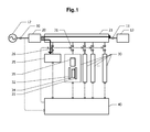
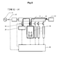
Fig. 1 illustrates a block diagram of a power supply device according to Embodiment 1. An AC power is supplied from acommercial power source 12 to aninput terminal 10. Anelectric load 13 is connected to anoutput terminal 11. Theelectric load 13 is, for example, a transceiver of a radio base station on a mobile communication network. An AC-DC converter 20 converts the AC power input to theinput terminal 10 to a DC power. The DC power is output to theoutput terminal 11 via an electricpower transmission circuit 21, and is supplied to apower storage device 25 via the electricpower transmission circuit 21 and aswitching element 26. This allows thepower storage device 25 to be maintained in a fully charged state at all times. For thepower storage device 25, for example, a lead storage battery, a lithium ion secondary battery or a lithium ion capacitor may be used. - Multiple
primary batteries 30 are connected to the electricpower transmission circuit 21 via respectively associatedswitching elements 31. For theprimary batteries 30, a metal-air battery, for example, such as a zinc air battery, an aluminum air battery and a magnesium air battery may be used. - Each of the
primary batteries 30 includes a positive electrodecurrent collector 32, a negative electrodecurrent collector 33, a negative electrodeactive material 34 and anelectrolytic solution 35. During the standby, theelectrolytic solution 35 is separated from the negative electrodeactive material 34. A state where theelectrolytic solution 35 is separated from the negative electrodeactive material 34 is referred to as a "standby state". If theelectrolytic solution 35 is brought into contact with the negative electrodeactive material 34, an electromotive force is generated. A state where theelectrolytic solution 35 comes into contact with the negative electrodeactive material 34 and the electromotive force is generated is referred to as an "operation state". - Measurement values of a voltage applied to the
input terminal 10, a voltage across terminals of thepower storage device 25, and a voltage across terminals of each of the multipleprimary batteries 30 are input to acontroller 40. Based on the input measurement values of the voltages, thecontroller 40 performs an on-off control ofswitching elements primary batteries 30. -
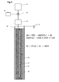
Fig. 2 illustrates a cross-sectional view of the primary battery 30 (refer toFig. 1 ) which is used in the power supply device according to Embodiment 1. The inside of a pouch-shaped separator 36 is filled with the negative electrodecurrent collector 33 and the negative electrodeactive material 34. For the negative electrodeactive material 34, for example, metal particles made of metallic zinc, metallic aluminum and metallic magnesium may be used. For the negative electrodecurrent collector 33, for example, a metal plate made of nickel may be used. For theseparator 36, for example, a porous membrane made of polyethylene or polypropylene, nonwoven fabric made of resin, or nonwoven fabric made of glass fiber is used. - The positive electrode
current collector 32 adheres to an outer side surface of theseparator 36. The positiveelectrode current collector 32 has a structure where a conductive material such as carbon black is coated on a base such as carbon cloth, carbon paper or the like. The conductive material includes a catalyst and an adhesive. For the catalyst, for example, manganese dioxide may be used. For the adhesive, for example, polyvinylidene fluoride may be used. The positive electrodecurrent collector 32 has multiple fine apertures allowing oxygen to pass therethrough. The oxygen in the atmosphere acts as a positive electrode active material. The negative electrodecurrent collector 33 and the positive electrodecurrent collector 32 are connected to theoutput terminals 37 of theprimary battery 30. - A solvent is accumulated inside the
reservoir tank 51. Thereservoir tank 51 is connected to anelectrolyte containing chamber 53 via an on-offvalve 52. Crystals of electrolyte are contained inside theelectrolyte containing chamber 53. The on-offvalve 52 is controlled by thecontroller 40. If the on-offvalve 52 is turned on, the solvent inside thereservoir tank 51 is injected into theelectrolyte containing chamber 53. The crystals of the electrolyte contained inside theelectrolyte containing chamber 53 are dissolved in the solvent to generate the electrolytic solution. The generated electrolytic solution is injected to a space inside theseparator 36 through an electrolyticsolution injection port 50 provided on theseparator 36. As an example, water may be used for the solvent, and potassium hydroxide (KOH) may be used for the electrolyte. In this case, aqueous potassium hydroxide solution is injected into theseparator 36, as the electrolyte. The electrolytic solution may be contained in thereservoir tank 51 to omit theelectrolyte containing chamber 53. - If the electrolytic solution is injected into the
separator 36, zinc (Zn) of the negative electrodeactive material 34 and hydroxide ions (OH-) in the electrolytic solution react to generate tetra hydroxonium zincate (Zn(OH)4 2-) and electrons. The tetra hydroxonium zincate is decomposed to generate zinc oxide (ZnO), hydroxide ions and the water. The generated electrons are collected in the negative electrodecurrent collector 33. If the electric load is connected across theoutput terminals 37, the electrons collected in the negative electrodecurrent collector 33 are supplied to the positive electrodecurrent collector 32 through the electric load. - The oxygen serving as the positive electrode active material, the electrons supplied to the positive electrode
current collector 32 and the water react to generate the hydroxide ions. The hydroxide ions are transported through theseparator 36 to reach the negative electrodeactive material 34. As described above, if the metal-air battery discharges the electricity, the negative electrodeactive material 34 is oxidized, and the metal oxide, for example zinc oxide, is accumulated. -
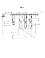
Fig. 3 illustrates an equivalent circuit diagram of the power supply device according to Embodiment 1. Avoltmeter 24 measures the voltage of the commercial power source 12 (refer toFig. 1 ), which is applied to theinput terminal 10. The measured result of thevoltmeter 24 is input to thecontroller 40. Thecontroller 40 monitors a measurement value of the voltmeter 24 (voltage of thecommercial power source 12, which is applied to the input terminal 10). Thecontroller 40 compares the measurement value of thevoltmeter 24 with a specified voltage value, and determines that normal power supply from the commercial power source 12 (refer toFig. 1 ) is stopped, if the measurement value of thevoltmeter 24 falls to the specified voltage value or less. - The electric
power transmission circuit 21 includes abus line 22 anddiodes 23. Input and output terminals of thepower storage device 25 are connected to thebus line 22 via the switchingelement 26. Avoltmeter 27 measures the voltage across the input and output terminals of thepower storage device 25. The measured result of thevoltmeter 27 is input to thecontroller 40. As long as there is no special circumstance, the switchingelement 26 is switched on at all times. Therefore, the voltage measured by thevoltmeter 27 is equal to the voltage applied to thebus line 22. - The multiple
primary batteries 30 are connected to thebus line 22 so as to be in parallel with one another via the respectively associated switchingelements 31, and so as to be in parallel with thepower storage device 25. Thediode 23 is arranged for each ofprimary batteries 30, and is connected to theprimary battery 30 in series. Thediode 23 is connected such that the direction of the discharging current from theprimary battery 30 corresponds to the forward direction. For this reason, a charged current is prohibited from flowing into theprimary battery 30. When the potential of the positive electrode of theprimary battery 30 becomes lower than the potential of thebus line 22, a control for preventing the inflow of the charged current may be performed by switching off the switchingelement 31. In a case of performing this control, thediodes 23 may be omitted. -
Multiple voltmeters 38 measure the voltages across the output terminals of the respectiveprimary batteries 30. The measured result is input to thecontroller 40. Aswitch 30A indicated within a dashed line illustrating theprimary battery 30 represents that theprimary battery 30 has two states of the standby state and the operation state. The off-state and the on-state of theswitch 30A respectively correspond to the standby state and the operation state. - The
power storage device 25 outputs a required voltage by connecting the lead storage batteries to one another in series, the number of which corresponds to the required voltage for theelectric load 13. Theprimary battery 30 has a configuration where multiple zinc-air batteries are connected to one another in series such that an open circuit voltage thereof is slightly higher than the open circuit voltage of thepower storage device 25. - The distance from the
output terminal 11 to a position on thebus line 22 to which each of the multipleprimary batteries 30 is connected is shorter than the distance from theoutput terminal 11 to a position on thebus line 22 to which thepower storage device 25 is connected. When the electric power is supplied from theprimary battery 30 to the electric load 13 (refer toFig. 1 ), it is possible to reduce the effect of resistance on thebus line 22 by shortening the distance from theprimary battery 30 to theoutput terminal 11. - Referring to
Figs. 4 to 8 , an operation of a power supply circuit according to Embodiment 1 will be described.
Fig. 4 illustrates an example of time changes in the voltage of the bus line 22 (refer toFig. 3 ) and the voltages across the terminals of the primary battery 30 (refer toFig. 1 ). InFig. 4 , a solid line of a voltage v1 in the upper row represents the voltage of the bus line 22 (refer toFig. 3 ), a solid line of a voltage v2 in the middle row represents the voltage across the terminals of the primary battery 30 (refer toFig. 1 ) to be firstly operated, and a solid line of a voltage v3 in the lower row represents the voltage across the terminals of the primary battery 30 (refer toFig. 1 ) to be secondly operated. Since the switching element 26 (refer toFig. 3 ) is the on-state at all times, the voltage v1 of thebus line 22 can be measured by the voltmeter 27 (refer toFig. 3 ). - At time t0, the power supply from the commercial power source 12 (refer to
Fig. 1 ) is assumed to be stopped. The measurement value of the voltmeter 24 (refer toFig. 3 ) falls to a specified voltage value or less. Accordingly, thecontroller 40 detects that the power supply is stopped from thecommercial power source 12. At the time t0, as illustrated inFig. 5 , the discharge from thepower storage device 25 is started, and the electric power is supplied to theelectric load 13 via the electricpower transmission circuit 21. As illustrated inFig. 4 , the voltage v1 across the terminals of thepower storage device 25 is lowered with the lapse of time by electric discharge of thepower storage device 25. - At time t1 illustrated in
Fig. 4 , the voltage v1 of the bus line 22 (refer toFig. 3 ) is lowered to a voltage threshold value Va. If the controller 40 (refer toFig. 1 ) detects that the voltage v1 of the bus line 22 (refer toFig. 3 ) is lowered to the voltage threshold value Va, thecontroller 40 turns on the on-off valve 52 (refer toFig. 2 ) of theprimary battery 30 to be firstly operated. The electrolytic solution is injected to theprimary battery 30, and the voltage v2 across the terminals of theprimary battery 30 starts to rise. When the discharged current of thepower storage device 25 is within a range of a rated value, the voltage across the terminals of thepower storage device 25 corresponds to a state of charge (SOC) of thepower storage device 25. Accordingly, monitoring the voltage v1 of the bus line 22 (refer toFig. 3 ) is substantially equivalent to monitoring the SOC of thepower storage device 25. - At time t2, the voltage v2 across the terminals of the
primary battery 30 to which the electrolytic solution is injected reaches a rated open circuit voltage Vb. When the controller 40 (refer toFig. 1 ) detects that the voltage v2 across the terminals reaches the rated open circuit voltage Vb, the switching element 31 (refer toFig. 1 ) connected to theprimary battery 30 to which the electrolytic solution is injected is switched on. In the result, theprimary battery 30 changes from the standby state to the operation state. The discharged current starts to flow from theprimary battery 30, and thus the voltage v1 of the bus line 22 (refer toFig. 3 ) rises. Since voltage drop ΔVb occurs due to the internal resistance of theprimary battery 30, the voltage v1 of the bus line 22 (refer toFig. 3 ) rises to Vb-ΔVb. - As illustrated in
Fig. 6 , the electric power is supplied from theprimary battery 30 in the operation state to theelectric load 13. If the voltage v1 of the bus line 22 (refer toFig. 3 ) is higher than the open circuit voltage across the terminals of thepower storage device 25, that is, if the potential of the bus line 22 (refer toFig. 3 ) is higher than the potential of the positive electrode of thepower storage device 25, thepower storage device 25 is charged by using the discharge power from theprimary battery 30 in the operation state. If the power consumption increases in theelectric load 13, the discharge current increases in theprimary battery 30. As a result, the voltage drop due to the internal resistance of theprimary battery 30 increases, and thus the voltage v1 of thebus line 22 is lowered. If the voltage v1 of the bus line 22 (refer toFig. 3 ) is lower than the open circuit voltage across the terminals of thepower storage device 25, as illustrated inFig. 7 , thepower storage device 25 discharges the electricity. Therefore, the electric power is supplied to theelectric load 13 from both of theprimary battery 30 and thepower storage device 25. The charging and discharging of thepower storage device 25 are performed according to the power consumption of theelectric load 13. As a whole, the voltage v1 of thebus line 22 is lowered with the lapse of time. A sudden change in the power consumption, which is caused by theelectric load 13, also switches between charging and discharging of thepower storage device 25. - At time t3 in
Fig. 4 , the voltage v1 of thebus line 22 is lowered to a voltage threshold value Va, and the controller 40 (refer toFig. 1 ) starts to inject the electrolytic solution to theprimary battery 30 to be secondly operated. Accordingly, the voltage v3 across the terminals of theprimary battery 30 secondly operated rises. When the voltage v3 across the terminals reaches the rated open circuit voltage Vb, the controller 40 (refer toFig. 1 ) switches on the switching element 31 (refer toFig. 1 ) connected to theprimary battery 30 to be secondly operated, and switches off the switching element 31 (refer toFig. 1 ) connected to theprimary battery 30 firstly operated. Since the discharge current from theprimary battery 30 firstly operated no longer flows, the voltage v2 across the terminals of theprimary battery 30 maintains a substantially constant value. - As illustrated in
Fig. 8 , after time t4, theprimary battery 30 secondly operated discharges electricity. The charging and discharging of thepower storage device 25 are performed according to the power consumption of theelectric load 13. Even after the time t4, every time the voltage v1 of the bus line 22 (refer toFig. 3 ) is lowered to the voltage threshold value Va, the injecting the electrolytic solution to theprimary battery 30 to be subsequently operated is started. This enables the electric power to be successively supplied to theelectric load 13. - In Embodiment 1, during the period of the standby state of the primary battery 30 (refer to
Fig. 1 ), the negative electrode active material 34 (refer toFig. 2 ) and the electrolytic solution are not in contact with each other. Therefore, it is possible to prevent self-discharge and the deterioration of the battery. During the period (time t0 to t2 inFig. 4 ) until when the electrolytic solution is injected to theprimary battery 30 to generate the rated voltage, the electric power is supplied from thepower storage device 25 to theelectric load 13. Therefore, the power supply is continuously guaranteed. - As described above, the
controller 40 monitors the voltage of the commercial power source, which is applied to theinput terminal 10, and the SOC of thepower storage device 25, and based on the monitored result, supplies theoutput terminal 11 with the output of at least one primary battery out of the multipleprimary batteries 30. More specifically, thecontroller 40 supplies theoutput terminal 11 with the output of at least one primary battery out of the multipleprimary batteries 30, using detection of at least one event as a trigger, between the event that the voltage of the commercial power source, which is applied to theinput terminal 10, falls to the specified voltage value or less and the event that the SOC of thepower storage device 25 falls to the preset specified value or less. - It is only necessary to set the capacity of the
power storage device 25 to such a degree that the electric power can be supplied to theelectric load 13 during the period until theprimary battery 30 starts to be operated. Therefore, compared to a case of the backup using only thepower storage device 25, it is possible to further decrease the capacity thereof. If the capacity of thepower storage device 25 is decreased, the power consumption caused by the self-discharge of thepower storage device 25 is decreased. Therefore, even if thepower storage device 25 maintains the fully charged state, it is possible to reduce a power loss caused by the self-discharge. - Embodiment 1, as a trigger for operating the primary battery 30 (refer to
Fig. 1 ), adopts the monitored result (voltage v1 inFig. 4 ) of the SOC of the power storage device 25 (refer toFig. 1 ). As a trigger for firstly operating theprimary battery 30, the monitored result of the voltage of the commercial power source, which is applied to theinput terminal 10, may be adopted. For example, the on-off valve 52 (refer toFig. 2 ) of theprimary battery 30 to be firstly operated may be turned on after a lapse of the preset time for standby from when thecontroller 40 detects that the voltage of the commercial power source, which is applied to theinput terminal 10, falls to the specified voltage value or less. The time for standby is determined based on the available time for thepower storage device 25 to supply the sufficient electric power to the electric load 13 (refer toFig. 1 ). - Furthermore, as a trigger for operating the primary battery 30 (refer to
Fig. 1 ), both of the monitored result of the SOC of the power storage device 25 (refer toFig. 1 ) and the monitored result of the voltage of the commercial power source, which is applied to theinput terminal 10, may be adopted. -
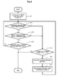
Fig. 9 illustrates an example of a flowchart in a process performed by thecontroller 40 in a case where both of the monitored result of the SOC of thepower storage device 25 and the monitored result of the voltage of the commercial power source, which is applied to theinput terminal 10, are adopted as the trigger for operating theprimary battery 30. The process in this flowchart starts from when thecontroller 40 detects that the voltage of the commercial power source falls to the specified voltage value or less. - If it is detected that the voltage of the commercial power source falls to the specified voltage value or less, a standby time decision counter is initialized in Step ST1. The initialized counter is decremented with the lapse of time and becomes zero when the time for standby elapses. In Step ST2, it is determined whether or not predetermined time for standby has elapsed. Specifically, it is determined whether or not the standby time decision counter has been decremented to become zero. If the predetermined time for standby has not yet elapsed, it is determined whether the SOC of the power storage device 25 (refer to
Fig. 1 ) is equal to or less than the specified value in Step ST3. If it is beyond the specified value, in Step ST 4, it is determined whether or not the voltage of the commercial power source has been restored to have the specified voltage value. If the voltage of the commercial power source has been restored, the process ends. If the voltage of the commercial power source has not yet been restored, the process returns to Step ST2. - In Step ST2, if it is determined that the predetermined time for standby has elapsed, or in Step ST3, if it is determined that the SOC of the
power storage device 25 is equal to or less than the specified value (corresponding to time t1 and t3 inFig. 4 ), in Step ST5, it is determined whether or not the standbyprimary battery 30 still remains. If the standbyprimary battery 30 does not remain, the process ends. If the standbyprimary battery 30 still remains, in Step ST6, the standbyprimary battery 30 is started to be operated. - The process in Step ST6 is the same as the process from the time t1 to t2 in
Fig. 4 . That is, the on-off valve 52 (refer toFig. 2 ) of theprimary battery 30 to be operated is turned on. If the open circuit voltage of theprimary battery 30 rises up to the rated voltage value, the switchingelement 31 is switched on. - Then, in Step ST7, the standby time decision counter is initialized, and the decrement process of the counter resumes. After initializing the standby time decision counter, the process returns to Step ST2. The initial value of the time for standby set in Step ST1 is not always the same as the initial value of the time for standby set in Step ST7. The initial value of the time for standby set in Step ST1 may be set to such a value that the fully charged
power storage device 25 can supply the sufficient electric power to the electric load 13 (refer toFig. 1 ). The initial value of the time for standby set in Step ST7 may be set to such a value that theprimary battery 30 can supply the sufficient electric power to the electric load 13 (refer toFig. 1 ). - Referring to
Fig. 10 , a control in a case where an operation of the operatedprimary battery 30 is poor will be described. -
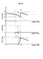
Fig. 10 illustrates an example of time changes in the voltage of the bus line 22 (refer toFig. 3 ) and the voltage across the terminals of the primary battery 30 (refer toFig. 1 ). Hereinafter, different points from the time changes illustrated inFig. 4 will be described. At the time t1, theprimary battery 30 is changed to the operation state by turning on the on-off valve 52 (refer toFig. 2 ) of the primary battery to be firstly operated. As illustrated in the second row inFig. 10 , this process allows the voltage v2 across the terminals of theprimary battery 30 to be firstly operated to start to rise. However, since there is a certain abnormality in theprimary battery 30, as compared to the case inFig. 4 , the rising rate of the voltage v2 across the terminals is slow. Theprimary battery 30 corresponding to the on-off valve 52 (refer toFig. 2 ) that is turned on is changed to the operation state for enabling the output of the electric power. Even if a certain abnormality causes the electrolytic solution not to be injected to a space containing the negative electrodeactive material 34, and thus the electromotive force is not generated, the state of theprimary battery 30 corresponding to the on-offvalve 52 opened is referred to as the "operation state". - Even if monitoring time tr has elapsed from the time t1, the voltage v2 across the terminals of the operated
primary battery 30 does not reach the rated open circuit voltage Vb. Thecontroller 40 monitors whether the operation of the operatedprimary battery 30 is good or poor. Thecontroller 40, when detecting that at the time t5 when the monitoring time tr has elapsed from the time t1, the voltage v2 across the terminals does not reach the rated open circuit voltage Vb, determines that theprimary battery 30 is poorly operated. If the operatedprimary battery 30 is determined to be poorly operated, thecontroller 40 turns on the on-off valve 52 (refer toFig. 2 ) of theprimary battery 30 to be subsequently operated. - As illustrated in the third row in
Fig. 10 , the voltage v3 across the terminals of theprimary battery 30 to be subsequently operated starts to rise. At time t6, the voltage v3 across the terminals reaches the rated open circuit voltage Vb. Thecontroller 40, when detecting that the voltage v3 across the terminals has reached the rated open circuit voltage Vb, switches on the switching element 31 (refer toFig. 1 ) connected to theprimary battery 30 which has reached the rated open circuit voltage Vb. The voltage v3 across the terminals of theprimary battery 30 is lowered by the voltage drop ΔVb caused by the internal resistance. The voltage v1 of the bus line 22 (refer toFig. 3 ) is lowered to a voltage Vc which is lower than the voltage threshold value Va, during the time until time 6. When the switchingelement 31 of the operatedprimary battery 30 is switched on, the voltage v1 of thebus line 22 is restored to Vb-ΔVb. - After the time t6, the electric power is supplied from the secondly operated
primary battery 30 to the electric load 13 (refer toFig. 1 ). If the voltage v1 of thebus line 22 is lowered to the voltage threshold value Va, thecontroller 40 turns on the on-off valve 52 (refer toFig. 2 ) of theprimary battery 30 to be subsequently operated. - When one
primary battery 30 is poorly operated, it is possible to suppress the voltage v1 of the bus line 22 (refer toFig. 3 ) from being excessively lowered by changing the state of the otherprimary battery 30 to the operation state. -
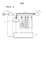
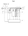
Fig. 11 illustrates a block diagram during a backup operation of the power supply device according to a modification example of Embodiment 1. In Embodiment 1 illustrated inFigs. 1 to 9 , as illustrated inFig. 6 , when the power supply is stopped from thecommercial power source 12, the states of theprimary batteries 30 are changed to the operation states sequentially and one by one. In the modification example illustrated inFig. 11 , the states of multipleprimary batteries 30 are simultaneously changed to the operation state.Fig. 11 illustrates an example where twoprimary batteries 30 are simultaneously left in the operation state. - The number of the
primary batteries 30 to be simultaneously operated is decided depending on the electric power required by theelectric load 13. It is possible to supply the sufficient electric power to theelectric load 13 by simultaneously operating the multipleprimary batteries 30. The number of theprimary batteries 30 to be simultaneously operated is stored in astorage device 41 inside thecontroller 40. The electric power required by theelectric load 13 varies for each radio base station, for example. The power supply device according to the modification example can set a value which is to be stored in thestorage device 41 for each radio base station. Accordingly, the power supply device can be applied to various scales of the radio base station. - When simultaneously operating the multiple
primary batteries 30, thecontroller 40 independently monitors each voltage across the terminals of the operatedprimary batteries 30. When determining that at least oneprimary battery 30 out of the operatedprimary batteries 30 is poorly operated, thecontroller 40 changes the states of the same number of the otherprimary batteries 30 as the number of theprimary batteries 30 determined to be poorly operated, to the operation states. This can suppress the voltage v1 of the bus line 22 (refer toFig. 3 ) from being excessively lowered. -
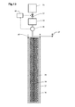
Fig. 12 illustrates a schematic diagram of a primary battery according to Embodiment 2. Hereinafter, different points from Embodiment 1 illustrated inFig. 2 will be described, and the same configurations will not be repeatedly described. Agravimeter 55 measures weights of the positive electrodecurrent collector 32, the negative electrodecurrent collector 33, the negative electrodeactive material 34 and theseparator 36. Since thereservoir tank 51, the on-offvalve 52 and theelectrolyte containing chamber 53 are fixed to a base, the weights thereof are not measured by thegravimeter 55. The measured result is input to thecontroller 40. If the electrolytic solution is injected into theseparator 36, the weights measured by thegravimeter 55 are increased. It is possible to estimate an injection amount of the electrolytic solution by checking the increase in weight. Thecontroller 40 stores a tendency of the increase in weight when the electrolytic solution is normally injected into theseparator 36. By comparing the tendency of the increase in the weight measured by thegravimeter 55 with the tendency of the increase in the normal weight stored in advance, it is possible to detect whether or not the injection of the electrolytic solution is normally performed. - The
controller 40 monitors the result measured by thegravimeter 55 after the time t1 illustrated inFig. 10 . When the tendency of the increase in the weight measured by thegravimeter 55 departs from a normal range, thecontroller 40 determines that the electrolytic solution is not normally injected into theseparator 36. - As illustrated in
Fig. 13 , instead of measuring the weight by using thegravimeter 55, acurrent meter 56 may be inserted to an injection route of the electrolytic solution. The measured result of thecurrent meter 56 is input to thecontroller 40. By measuring a flow rate of the electrolytic solution by thecurrent meter 56, it is possible to determine whether or not the electrolytic solution is normally injected into theseparator 36. - As described above, by monitoring an injection state of the electrolytic solution using the
gravimeter 55, thecurrent meter 56 or the like, it is possible to determine whether the operation of the operatedprimary battery 30 is good or poor. The determination method adopted in Embodiment 1, as to whether the operation is good or poor, based on the voltage across the terminals of theprimary battery 30 may be used in conjunction with the determination method adopted in Embodiment 2, as to whether the operation is good or poor, based on the injection state of the electrolytic solution. - Next, a power supply device according to Embodiment 3 will be described. The block diagram of the power supply device according to Embodiment 3 is the same as the block diagram of the power supply device according to Embodiment 1 illustrated in
Fig. 1 . In Embodiment 1, thepower storage device 25 maintains the fully charge state for the period when the electric power is supplied from thecommercial power source 12, but it is not necessarily to maintain the fully charged state. Thepower storage device 25 may store an electrical energy required during a period until theprimary battery 30 starts to be operated when a power failure occurs. - In Embodiment 1, as the
power storage device 25, a small capacity device is adopted, which can store the electrical energy required during the period until theprimary battery 30 starts to be operated when the power failure occurs. Thepower storage device 25 adopted to Embodiment 3 has a larger capacity than the capacity of thepower storage device 25 adopted to Embodiment 1. Therefore, without a need to maintain the fully charged state of thepower storage device 25, it is possible to store the sufficient electrical energy. - The
controller 40 monitors the state of charge (SOC) of thepower storage device 25, and charges thepower storage device 25 by switching on the switchingelement 26, if the state of charge is lower than a reference value. If the state of charge is restored to the reference value or more, thecontroller 40 switches off the switchingelement 26. In this manner, thecontroller 40 controls the charging of thepower storage device 25 so as to maintain the state of charge required for the backup. - In Embodiment 3, the
power storage device 25 which has the larger capacity than thestorage device 25 in Embodiment 1 is adopted. However, similarly to Embodiment 1, it is possible to reduce the power consumption caused by the self-discharge by not fully charging thepower storage device 25. - Hitherto, while the embodiments of the present invention have been described, the embodiments of the present invention are not intended to be limited thereto. For example, it will be apparent to those skilled in the art that various modifications, improvements and combinations can be made. Reference Signs List
- 10
- input terminal
- 11
- output terminal
- 12
- commercial power source
- 13
- electric load
- 20
- AC-DC converter
- 21
- electric power transmission circuit
- 22
- bus line
- 23
- diode
- 24
- voltmeter
- 25
- power storage device
- 26
- switching element
- 27
- voltmeter
- 30
- primary battery
- 31
- switching element
- 32
- positive electrode current collector
- 33
- negative electrode current collector
- 34
- negative electrode active material
- 35
- electrolytic solution
- 36
- separator
- 37
- output terminal
- 38
- voltmeter
- 40
- controller
- 41
- storage device
- 50
- electrolytic solution injection port
- 51
- reservoir tank
- 52
- on-off valve
- 53
- electrolyte containing chamber
- 55
- gravimeter
- 56
- current meter
Claims (8)
- A power supply device comprising:an input terminal to which an electric power is supplied from a commercial power source;an output terminal connected to an electric load;a power storage device to be charged by the electric power supplied from the input terminal and supplying the electric power to the output terminal;a primary battery; anda controller monitoring a voltage of the commercial power source, which is applied to the input terminal, and a state of charge of the power storage device,wherein the controller supplies an output power of the primary battery to the output terminal, when detecting that the voltage of the commercial power source falls to a specified voltage value or less and the state of charge of the power storage device falls to a specified value or less.
- The power supply device according to claim 1, wherein the primary battery is a metal-air battery.
- The power supply device according to claim 2, wherein the primary battery is left in a standby state where a negative electrode active material and an electrolytic solution are separated from each other, and
wherein the controller supplies the output power of the primary battery to the output terminal by bringing the electrolytic solution of the primary battery into contact with the negative electrode active material, when detecting that the voltage of the commercial power source falls to the specified voltage value or less and the state of charge of the power storage device falls to the specified value or less. - The power supply device according to claim 3, further comprising:other multiple primary batteries in addition to the primary battery,wherein the controller supplies the output terminal with the output powers of the primary batteries, the number of which depends on the electric power required by the electric load connected to the output terminal.
- The power supply device according to claim 1, further comprising:other multiple primary batteries in addition to the primary battery,wherein the controller, based on the monitored result on the state of charge of the power storage device, changes a state of at least one primary battery out of the multiple primary batteries to an operation state enabling power supply to the output terminal, determines whether the operation of the operated primary battery is good or poor, and changes a state of another non-operated primary battery to the operation state, if the operation state of the operated primary battery is poor.
- The power supply device according to claim 5, wherein the controller measures a voltage across terminals of the operated primary battery, and determines whether the operation state of the operated primary battery is good or bad, based on the measured result on the voltage across the terminals.
- The power supply device according to claim 5, wherein the primary battery is a metal-air battery, and before being operated, is left in a standby state where a negative electrode active material and an electrolytic solution are separated from each other, and
wherein the controller changes the state of the primary battery to the operation state by injecting the electrolytic solution of the primary battery to a space containing the negative electrode active material, and determines whether the operation state of the primary battery is good or poor by monitoring an injection state of the electrolytic solution. - The power supply device according to claim 7,
wherein each of the primary batteries is connected to the output terminal via a switching element, and
wherein the switching element connected to the primary battery in the standby state is left in an off-state, and the controller switches on the switching element connected to the primary battery the state of which is changed to the operation state.
Applications Claiming Priority (2)
| Application Number | Priority Date | Filing Date | Title |
|---|---|---|---|
| JP2012196297A JP5963620B2 (en) | 2012-09-06 | 2012-09-06 | Power supply |
| JP2012196295A JP6055246B2 (en) | 2012-09-06 | 2012-09-06 | Power supply |
Publications (2)
| Publication Number | Publication Date |
|---|---|
| EP2706647A2 true EP2706647A2 (en) | 2014-03-12 |
| EP2706647A3 EP2706647A3 (en) | 2014-11-05 |
Family
ID=49110971
Family Applications (1)
| Application Number | Title | Priority Date | Filing Date |
|---|---|---|---|
| EP20130020085 Withdrawn EP2706647A3 (en) | 2012-09-06 | 2013-08-29 | Power supply device |
Country Status (3)
| Country | Link |
|---|---|
| US (1) | US9431852B2 (en) |
| EP (1) | EP2706647A3 (en) |
| KR (2) | KR20140032313A (en) |
Cited By (1)
| Publication number | Priority date | Publication date | Assignee | Title |
|---|---|---|---|---|
| WO2019040155A1 (en) * | 2017-08-21 | 2019-02-28 | Google Llc | System and method for monitoring and controlling a back-up power supply using temperature controlled batteries |
Families Citing this family (4)
| Publication number | Priority date | Publication date | Assignee | Title |
|---|---|---|---|---|
| JP2015197392A (en) * | 2014-04-02 | 2015-11-09 | ホシデン株式会社 | Liquid presence detector with power source and air improving apparatus provided with the liquid presence detector |
| JP2015216719A (en) * | 2014-05-08 | 2015-12-03 | 富士通株式会社 | Power supply device, power supply control method and base station device |
| CN109120058A (en) * | 2017-06-23 | 2019-01-01 | 中兴通讯股份有限公司 | Power supply monitoring system, communication equipment |
| KR20210016795A (en) * | 2019-08-05 | 2021-02-17 | 주식회사 엘지화학 | Energy hub apparatus and energy managemnet method |
Citations (1)
| Publication number | Priority date | Publication date | Assignee | Title |
|---|---|---|---|---|
| JP2007189813A (en) | 2006-01-12 | 2007-07-26 | Nec Mobiling Ltd | Individual receiver |
Family Cites Families (17)
| Publication number | Priority date | Publication date | Assignee | Title |
|---|---|---|---|---|
| US5208526A (en) * | 1990-07-19 | 1993-05-04 | Luz Electric Fuel Israel Ltd. | Electrical power storage apparatus |
| JP3733554B2 (en) | 1994-10-31 | 2006-01-11 | 富士通株式会社 | Battery-powered electronic equipment |
| JPH08154344A (en) | 1994-11-25 | 1996-06-11 | Japan Storage Battery Co Ltd | Uninterruptible ac power supply apparatus |
| KR20000017774A (en) | 1999-12-03 | 2000-04-06 | 김동연 | A power supply control circuit for digital electronic device |
| US6774602B2 (en) | 2002-06-14 | 2004-08-10 | Delphi Technologies, Inc. | Apparatus and method for providing temporary power |
| JP3770212B2 (en) | 2002-06-25 | 2006-04-26 | 日本電気株式会社 | Battery device control method |
| GB0217767D0 (en) | 2002-07-31 | 2002-09-11 | Xp Energy Systems Ltd | Improvements in or relating to power supply |
| US7157171B2 (en) * | 2003-05-09 | 2007-01-02 | Nanotek Instruments, Inc. | Metal-air battery with programmed-timing activation |
| US20050105229A1 (en) | 2003-11-14 | 2005-05-19 | Ballard Power Systems Corportion | Two-level protection for uninterrupted power supply |
| JP2008535156A (en) | 2005-03-22 | 2008-08-28 | ミート カンパニー リミテッド | Air zinc battery |
| JP4835551B2 (en) | 2007-08-27 | 2011-12-14 | パナソニック株式会社 | Power supply |
| JP2009089454A (en) | 2007-09-27 | 2009-04-23 | Toshiba Corp | Power supply circuit |
| JP2011024322A (en) | 2009-07-15 | 2011-02-03 | Equos Research Co Ltd | Control device |
| KR101094055B1 (en) * | 2009-12-15 | 2011-12-19 | 삼성에스디아이 주식회사 | Energy Storage System |
| CN102148531A (en) * | 2010-02-10 | 2011-08-10 | 西安锐信科技有限公司 | Power supply method, device and system for storage batteries |
| CN102593941A (en) | 2012-02-14 | 2012-07-18 | 华为技术有限公司 | Energy storage system and energy storage method based on communication base station |
| CN102593907A (en) | 2012-02-29 | 2012-07-18 | 华为技术有限公司 | Power supply method and device as well as base station |
-
2013
- 2013-08-06 KR KR1020130093046A patent/KR20140032313A/en active Application Filing
- 2013-08-29 EP EP20130020085 patent/EP2706647A3/en not_active Withdrawn
- 2013-08-29 US US14/013,167 patent/US9431852B2/en not_active Expired - Fee Related
-
2015
- 2015-01-28 KR KR1020150013625A patent/KR101566864B1/en active IP Right Grant
Patent Citations (1)
| Publication number | Priority date | Publication date | Assignee | Title |
|---|---|---|---|---|
| JP2007189813A (en) | 2006-01-12 | 2007-07-26 | Nec Mobiling Ltd | Individual receiver |
Cited By (3)
| Publication number | Priority date | Publication date | Assignee | Title |
|---|---|---|---|---|
| WO2019040155A1 (en) * | 2017-08-21 | 2019-02-28 | Google Llc | System and method for monitoring and controlling a back-up power supply using temperature controlled batteries |
| US10664365B2 (en) | 2017-08-21 | 2020-05-26 | Google Llc | System and method for monitoring and controlling a back-up power supply using temperature controlled batteries |
| TWI702770B (en) * | 2017-08-21 | 2020-08-21 | 美商谷歌有限責任公司 | System and method for monitoring and controlling a back-up power supply using temperature controlled batteries |
Also Published As
| Publication number | Publication date |
|---|---|
| KR101566864B1 (en) | 2015-11-06 |
| KR20150016403A (en) | 2015-02-11 |
| US20140062203A1 (en) | 2014-03-06 |
| EP2706647A3 (en) | 2014-11-05 |
| US9431852B2 (en) | 2016-08-30 |
| KR20140032313A (en) | 2014-03-14 |
Similar Documents
| Publication | Publication Date | Title |
|---|---|---|
| CN110679056B (en) | Battery charge management apparatus and method | |
| US9431852B2 (en) | Power supply device | |
| KR20100033509A (en) | Power system and assembled battery controlling method | |
| WO2017212815A1 (en) | Trickle charging power supply system | |
| JP2014191861A (en) | Back-up power supply device | |
| KR20110104883A (en) | Dc power supply device | |
| KR20100114097A (en) | Recharging device and recharging method | |
| CN111164824B (en) | Battery pack management device and battery pack system | |
| KR20140051881A (en) | Apparatus for battery management using battery's state of health and method thereof | |
| KR20170129290A (en) | Metal-air battery having a device for controlling the potential of the negative electrode | |
| KR101273811B1 (en) | Device and method for stabilizing of voltage of energy storage | |
| JP2013160582A (en) | Battery pack system and management method of battery pack system | |
| US10656215B2 (en) | Short circuit detection device | |
| KR101941964B1 (en) | Method for charging a zinc-air battery with limited potential | |
| JP2012182857A (en) | Dc power supply | |
| JP6055246B2 (en) | Power supply | |
| JP5488085B2 (en) | DC power supply | |
| JP2016119741A (en) | Battery system for vehicle | |
| JP5840093B2 (en) | Power supply | |
| JP2014054055A (en) | Power supply | |
| JP5963620B2 (en) | Power supply | |
| CN112968485A (en) | UPS lithium battery floating charge control circuit, lithium battery system and UPS lithium battery charge control method | |
| JP2004304931A (en) | Charging method and charging device for electric storage device | |
| KR20150142880A (en) | Energe storage system | |
| CN113511108B (en) | Control circuit, method and system |
Legal Events
| Date | Code | Title | Description |
|---|---|---|---|
| PUAI | Public reference made under article 153(3) epc to a published international application that has entered the european phase |
Free format text: ORIGINAL CODE: 0009012 |
|
| AK | Designated contracting states |
Kind code of ref document: A2 Designated state(s): AL AT BE BG CH CY CZ DE DK EE ES FI FR GB GR HR HU IE IS IT LI LT LU LV MC MK MT NL NO PL PT RO RS SE SI SK SM TR |
|
| AX | Request for extension of the european patent |
Extension state: BA ME |
|
| PUAL | Search report despatched |
Free format text: ORIGINAL CODE: 0009013 |
|
| AK | Designated contracting states |
Kind code of ref document: A3 Designated state(s): AL AT BE BG CH CY CZ DE DK EE ES FI FR GB GR HR HU IE IS IT LI LT LU LV MC MK MT NL NO PL PT RO RS SE SI SK SM TR |
|
| AX | Request for extension of the european patent |
Extension state: BA ME |
|
| RIC1 | Information provided on ipc code assigned before grant |
Ipc: H02J 9/06 20060101AFI20140926BHEP Ipc: H02J 7/34 20060101ALI20140926BHEP |
|
| STAA | Information on the status of an ep patent application or granted ep patent |
Free format text: STATUS: REQUEST FOR EXAMINATION WAS MADE |
|
| 17P | Request for examination filed |
Effective date: 20150505 |
|
| RBV | Designated contracting states (corrected) |
Designated state(s): AL AT BE BG CH CY CZ DE DK EE ES FI FR GB GR HR HU IE IS IT LI LT LU LV MC MK MT NL NO PL PT RO RS SE SI SK SM TR |
|
| STAA | Information on the status of an ep patent application or granted ep patent |
Free format text: STATUS: EXAMINATION IS IN PROGRESS |
|
| 17Q | First examination report despatched |
Effective date: 20210208 |
|
| STAA | Information on the status of an ep patent application or granted ep patent |
Free format text: STATUS: THE APPLICATION IS DEEMED TO BE WITHDRAWN |
|
| 18D | Application deemed to be withdrawn |
Effective date: 20210619 |