EP2706563A1 - Automated warehouse - Google Patents
Automated warehouse Download PDFInfo
- Publication number
- EP2706563A1 EP2706563A1 EP12779503.7A EP12779503A EP2706563A1 EP 2706563 A1 EP2706563 A1 EP 2706563A1 EP 12779503 A EP12779503 A EP 12779503A EP 2706563 A1 EP2706563 A1 EP 2706563A1
- Authority
- EP
- European Patent Office
- Prior art keywords
- opening
- holding space
- transferring apparatus
- space
- shield
- Prior art date
- Legal status (The legal status is an assumption and is not a legal conclusion. Google has not performed a legal analysis and makes no representation as to the accuracy of the status listed.)
- Granted
Links
Images






Classifications
-
- H—ELECTRICITY
- H10—SEMICONDUCTOR DEVICES; ELECTRIC SOLID-STATE DEVICES NOT OTHERWISE PROVIDED FOR
- H10P—GENERIC PROCESSES OR APPARATUS FOR THE MANUFACTURE OR TREATMENT OF DEVICES COVERED BY CLASS H10
- H10P72/00—Handling or holding of wafers, substrates or devices during manufacture or treatment thereof
- H10P72/30—Handling or holding of wafers, substrates or devices during manufacture or treatment thereof for conveying, e.g. between different workstations
- H10P72/34—Handling or holding of wafers, substrates or devices during manufacture or treatment thereof for conveying, e.g. between different workstations the wafers being stored in a carrier, involving loading and unloading
- H10P72/3404—Storage means
-
- H—ELECTRICITY
- H10—SEMICONDUCTOR DEVICES; ELECTRIC SOLID-STATE DEVICES NOT OTHERWISE PROVIDED FOR
- H10P—GENERIC PROCESSES OR APPARATUS FOR THE MANUFACTURE OR TREATMENT OF DEVICES COVERED BY CLASS H10
- H10P72/00—Handling or holding of wafers, substrates or devices during manufacture or treatment thereof
- H10P72/30—Handling or holding of wafers, substrates or devices during manufacture or treatment thereof for conveying, e.g. between different workstations
- H10P72/34—Handling or holding of wafers, substrates or devices during manufacture or treatment thereof for conveying, e.g. between different workstations the wafers being stored in a carrier, involving loading and unloading
- H10P72/3406—Handling or holding of wafers, substrates or devices during manufacture or treatment thereof for conveying, e.g. between different workstations the wafers being stored in a carrier, involving loading and unloading involving removal of lid, door or cover
-
- H—ELECTRICITY
- H10—SEMICONDUCTOR DEVICES; ELECTRIC SOLID-STATE DEVICES NOT OTHERWISE PROVIDED FOR
- H10P—GENERIC PROCESSES OR APPARATUS FOR THE MANUFACTURE OR TREATMENT OF DEVICES COVERED BY CLASS H10
- H10P72/00—Handling or holding of wafers, substrates or devices during manufacture or treatment thereof
- H10P72/30—Handling or holding of wafers, substrates or devices during manufacture or treatment thereof for conveying, e.g. between different workstations
- H10P72/34—Handling or holding of wafers, substrates or devices during manufacture or treatment thereof for conveying, e.g. between different workstations the wafers being stored in a carrier, involving loading and unloading
- H10P72/3408—Docking arrangements
Definitions
- the present invention relates to automated warehouses and, in particular, to an automated warehouse which stores articles in a clean space.
- Reticles have been used for manufacturing electronic parts, and are stored in a clean stocker placed in a clean room (See PTL 1 , for example). In the clean stocker, the reticles are taken out of pods for storage, and the ambient inside the clean stocker chassis needs to be kept from volatile impurities.
- a clean stocker disclosed in PTL 1 is equipped with a clean gas supply unit, placed in the upper part of the chassis of the clean stocker, to supply clean gas in order to prevent the volatile impurities from entering the chassis.
- the above conventional structure requires the clean gas to be supplied to spaces for holding and transporting reticles taken out of pods; specifically, all the spaces inside a pod opener, inside a rotation rack, and between the pod opener and the rotation rack (transportation route for the reticles).
- a chemical filter for the clean gas supply unit is a very expensive expendable, and the life of the chemical filter decreases with an increasing amount of airflow.
- the chemical filter will have to be replaced in a short period of time and the resulting expenses for the storage will increase.
- the expenses will further increase in the case where the ambience inside the chassis is to be kept from moisture as well as the volatile impurities (hereinafter referred to as "clean space").
- the present invention is conceived in view of the above problems and aims to provide an object to implement an automated warehouse which is capable of efficiently storing articles in a clean space.
- An automated warehouse places an article in a case, and brings in and takes out the article.
- the automated warehouse includes: a storage rack which stores articles including the article; a load port which holds the case and includes a loading and unloading space for loading and unloading the article to and from the held case; a transferring apparatus which includes a holding space for holding the article and transfers the article between the holding space and the storage rack and between the holding space and the case held in the loading and unloading space, the holding space being kept clean; and a first shield which closes the holding space and travels together with the transferring apparatus.
- the above structure allows the holding space alone to be kept clean instead of the entire transportation route of articles. Hence the space to be cleaned needs to be smaller, which contributes to a decrease in storage expenses and efficient storage of articles.
- the language "closed" in the Description does not necessarily mean sealing a space as far as impurities are kept from entering the space.
- the first shield may seal the opening for the holding space to keep impurities from entering the holding space.
- the first shield may be placed so that there is a narrow clearance between the first shield and the opening for the holding space in order to let the clean gas in the holding space always out from the clearance.
- the load port may travel together with the transferring apparatus so that the holding space of the transferring apparatus and the loading and unloading space are connected with each other.
- the first shield may close to keep clean the loading and unloading space and the holding space connected with each other.
- the above features allow the article taken out of a case at the load port to be transported to the storage rack without moving the article out of a clean space. Hence the space to be cleaned needs to be smaller, and contamination of the article is effectively prevented.
- the first shield may include: a cylinder for containing the transferring apparatus rotatable; a first opening formed on a side of the cylinder to face the load port; and a second opening formed on a side of the cylinder to face the storage rack.
- the transferring apparatus may: rotate to a position where an opening for the holding space faces the first opening, and transfer the article between the holding space and the load port; rotate to a position where the opening for the holding space faces the second opening, and transfer the article between the holding space and the storage rack; and rotate to a position where the opening for the holding space faces an inner sidewall of the cylinder, and travel together with the first shield with the holding space closed.
- the transferring apparatus may rotate inside the first shield so that the opening for the holding space can be exposed only when the apparatus transfers the article and closed when apparatus travels. Hence the space to be cleaned needs to be smaller, and contamination of the article is effectively prevented.
- the transferring apparatus may further be capable of vertically traveling inside the cylinder, and prior to the rotation inside the cylinder, the transferring apparatus may ascend or descend to a position where the opening for the holding space does not face either the first opening or the second opening. Such a feature prevents the opening from being exposed while the transferring apparatus is rotating.
- the automated warehouse may include a second shield which is attached to an outer sidewall of the cylinder, travels together with the transferring apparatus and the first shield, and closes a loading and unloading opening on the storage rack for transferring the article when arriving at a position to face the storage rack.
- the second shield may include a connecting hole for selectively connecting between the second opening on the first shield and a part of the loading and unloading opening on the storage rack, the selective connection being made only to the part through which the article passes.
- the present invention allows a holding space alone to be kept clean instead of the entire transportation route of articles. Hence the space to be cleaned needs to be smaller and contamination of the articles is successfully prevented.
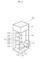
- FIG. 1 schematically shows a clean stocker 100 which exemplifies an automated warehouse according to Embodiment 1 of the present invention.
- the clean stocker 100 mainly includes a storage rack 110, a load port 120, a transferring apparatus 130, a first shield 140, a second shield 150, an elevator guide 160, and a cleaning unit (fan filter unit or FFU) 170.
- the clean stocker 100 is installed in a clean room of a semiconductor factory or a liquid crystal display factory, and separately stores reticles (articles) for exposure for either semiconductors or liquid crystal substrates, and pods (cases) for containing the reticles.
- the storage rack 1 10 stores a reticle taken out of a pod.
- the structure of the storage rack 110 shall not be defined in particular.
- the storage rack 110 includes multiple reticle chambers 110a. More specifically, the reticle chambers 110a are vertically arranged into a first column (on the left column in FIG. 1 ) and a second column (on the right column in FIG. 1 ) so that the first and second columns are provided around the transferring apparatus 130.
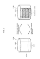
- FIG. 2 shows an exemplary reticle chamber 110a.
- a reticle chamber 110a includes an inner cover 111 formed in a cylinder, and an outer cover 112 which is slightly larger than the inner cover 111 and formed in a cylinder.
- the inner cover 111 and the outer cover 112 respectively have an opening 111 1 a and an opening 112a on their sides.
- the inner cover 111 includes racks to place reticles and is fixed so that the opening 1 1 1 a faces the transferring apparatus 130.
- the inside of the inner cover 111 is kept clean by the cleaning unit 170.
- the outer cover 112 covers the inner cover 111 and rotates around the inner cover 111.
- the loading and unloading of the reticles is denied (the reticle chamber 110a closed).
- the outer cover 112 rotates and the openings 1 1 1 a and 112a overlap with each other (on the right in FIG. 2 ) the loading and unloading of the reticles is allowed (the reticle chamber 110a open). I n other words, the overlapping openings 111a and 112b form a loading and unloading opening 113 on the reticle chamber 110a.
- the load port 120 operates as an interface to bring in and take out a reticle contained in a pod, as well as a pod opener (loading and unloading apparatus) to place and take the reticle in and out of the pod.
- FIGS. 3 to 6 show operations of the load port 1 20 that works as a loading and unloading apparatus. Described with reference to FIGS. 3 to 6 are a structure of the load port 120 and operations to take a reticle out of a pod. It is noted that the process below is reversed to place the reticle in the pod, and the details thereof shall be omitted.
- the load port 120 has a loading and unloading space 121 to be used for taking a reticle out of a pod and placing the reticle into the pod. Moreover, the loading and unloading space 121 is kept clean by the cleaning unit 170.
- a pod 200 includes a cover 210 and a door 220 which are vertically separatable from each other. Moreover, on the top surface of the door 220, multiple protrusions 221 are provided to support the reticle.
- the load port 120 includes a locking part 122 to lock the cover 210 and a platform 123 to keep the door 220 thereon. It is noted that the platform 123 operates as an elevator which vertically travels with the door 220 kept thereon.
- the load port 120 has an opening on the top thereof.
- the locking part 122 is provided around the opening.
- the platform 123 is placed inside the load port 120 (specifically, in the loading and unloading space 121) to face the opening provided on the top of the load port 120.
- the top of the load port 1 20 and the platform surface (top surface) of the platform 123 are to be positioned on the same level when the platform 123 ascends to the uppermost level.
- the pod 200 is then placed on the platform 1 23 that ascends to the uppermost level. Hence, the opening of the load port 120 is closed by the pod 200.
- the loading and unloading space 121 is specifically a space which is partitioned by the load port 120 and the cover 210 of the pod 200.
- the opening of the load port 120 is slightly larger than the door 220 and smaller than the cover 210.
- the door 220 descends along with the platform 123 and the cover 210 is locked by the locking part 122.
- the cover 210 and the door 220 are vertically separated from each other.
- the reticle 230 placed over the door 220 is removed by the transferring apparatus 130, so that the load port 120 looks as shown in FIG. 5 .
- the cover 210 is closed again with the door 220 as shown in FI G. 6.
- the em pty pod 200 shown in FI G. 6 is taken out of the load port 120 by a pod transporting apparatus (not shown) and stored on a pod storage rack (not shown).
- the transferring apparatus 130 transfers a reticle between the storage rack 110 and the load port 1 20.
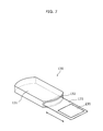
- FIG. 7 shows an exemplary structure of the transferring apparatus 130.
- the transferring apparatus 130 includes a holding space 131 for holding the reticle 230 therein.
- the transferring apparatus 130 uses a sliding fork 133 which ejects from and retracts into the holding space 131 via the opening 132, the transferring apparatus 130 transfers the reticle 230 between the storage rack 110 and the holding space 131 and between the holding space 131 and the pod 200 that is held in the loading and unloading space 121 of the load port 120.
- the holding space 131 is kept clean by the cleaning unit 170.
- the transferring apparatus 130 is placed inside a first shield 140.
- the first shield 140 has a cylinder 141 for accommodating the transferring apparatus 130, and first to third openings 142, 143, and 144 provided on the side of the cylinder 141.
- the first opening 142 is formed to face the load port 120.
- the second opening 143 is formed to face each of the reticle chambers 110a that belong to the first column of the storage rack 110.
- the third opening 144 is provided to face each of the reticle chambers 110a that belong to the second column of the storage rack 110. It is noted that the examples in FIGS. 8A to 8D show that the second opening 143 is positioned 90 degrees away from the first opening 142 in a clockwise direction, and the third opening 144 is positioned 180 degrees away from the first opening 142 in a clockwise direction.
- the transferring apparatus 130 is included in the cylinder 141 to be able to rotate and vertically travel inside the cylinder 141. Together with the transferring apparatus 130, the first shield 140 can vertically travel along the elevator guide 160 shown in FIG. 1 .
- a second shield 150 is attached to the outer sidewall of the cylinder 141 of the first shield 140, and travels together with the transferring apparatus 130 and the first shield 140.
- FIG. 11 shows that the second shield 150 travels to a position to face a reticle chamber 110a, and closes the loading and unloading opening 113 for reticles.
- the second shield 150 includes a connecting hole 151 for selectively connecting between (i) one of the second and third openings 143 and 144 on the first shield 140 and (ii) a part of the loading and unloading opening 113 on the reticle chamber 110a.
- the selective connection is made only to the part through which the reticle passes.
- the cleaning unit 170 may be an FFU. Using a tube and the like, the cleaning unit 170 supplies the inside of the storage rack 1 1 0 and the loading and unloading space 121 of the load port 120 with clean dry air (CDA) refined by a DCA refining apparatus provided outside.
- the DCA keeps clean the inside of the storage rack 110 and the loading and unloading space 121.
- the CDA is not directly supplied from the cleaning unit 170 to the holding space 131 of the transferring apparatus 130; however, when the holding space 131 connects to one of the storage rack 110 and the loading and unloading space 1 21 , the CDA is supplied from the storage rack 110 and the loading and unloading space 121 to the holding space 131 to keep the holding space 131 clean.
- the keeping clean means that the CDA supplied from the outside is directly or indirectly supplied to each of the units thorough the cleaning unit 170 that operates as an FFU.
- FIGS. 8A to 8D show exemplary operations of the transferring apparatus 130 inside the first shield 140.
- FIGS. 8A to 8D show exemplary operations of the transferring apparatus 130 inside the first shield 140.
- FI GS. 9 to 11 show positional relationships between the first and second shields 140 and 150 and the reticle chamber 110a. It is noted that the process below may be reversed to transfer a reticle on the storage rack 110 to the load port 120, and the details thereof shall be omitted.
- the transferring apparatus 130, the first shield 140 and the second shield 150 are moved along the elevator guide 160 to a position where the first opening 142 of the first shield 140 faces the load port 120 (not shown in FIG. 9 ).
- the transferring apparatus 130 is rotated inside the cylinder 141 to the position where the opening 132 for the holding space 131 faces the first opening 142 of the first shield 140. Hence, through the first opening 142, the loading and unloading space 121 of the load port 120 and the holding space 131 of the transferring apparatus 130 are connected with each other. The transferring apparatus 130 then obtains the reticle in the load port 120 with the sliding fork 133 and stores the reticle in the holding space 131.
- the transferring apparatus 130 is elevated inside the cylinder 141 to the position where the opening 132 for the holding space 131 does not face any of the opening 142, the opening 143, or the opening 144. Hence, the opening 132 for the holding space 131 is closed with the inner sidewall of the first shield 140.
- the transferring apparatus 130 in FIG. 8B is rotated inside the cylinder 141 as much as 90 degrees clockwise. It is noted that, prior to the rotation, the transferring apparatus 130 is elevated so that the opening 132 for the holding space 131 is kept closed with the inner sidewall of the cylinder 141. Such an operation contributes to preventing the CDA supplied from the cleaning unit 170 from leaking out of the holding space 131.
- the transferring apparatus 130 and the like are moved along the elevator guide 160 to a position where second opening 143 of the first shield 140 faces a reticle chamber 110a. More specifically, the connecting hole 151 on the second shield 150 is to face a position of a rack, included in the reticle chamber 110a, on which the reticle to be placed.
- the outer cover 1 1 2 of the reticle chamber 110a is rotated so that the openings 111a and 112a match with each other to form the loading and unloading opening 113.
- the loading and unloading opening 113 on the reticle chamber 110a is closed with the second shield 150 except the position of the connecting hole 151, which contributes to reducing the amount of the CDA to leak out of the reticle chamber 110a.
- the transferring apparatus 130 is lowered inside the cylinder 141 to the position where the opening 132 for the holding space 131 faces the second opening 143 of the first shield 140.
- the reticle chamber 110a connects to the holding space 131 of the transferring apparatus 130 through the first opening 142 and the connecting hole 151.
- the transferring apparatus 130 then transfers the reticle from the holding space 131 to the storage rack 110, using the sliding fork 133.
- the cleaning unit 170 has to keep clean.
- the features eliminates the need of keeping the entire transportation route of reticles as a conventional clean stocker has to do so, which contributes to reducing the space to be cleaned.
- the resulting smaller cleaning space allows storage expenses to decrease and contributes to efficient prevention of contamination of the reticles.
- the order of the each of the operations may partly be changed.
- the transferring apparatus 130 and the like may be first elevated to the position of the reticle chamber 110a, and then the transferring apparatus 130 inside the first shield 140 in FI G. 8B may be rotated as shown in FIG. 8C .
- the transferring apparatus 130 is elevated inside the cylinder 141 as shown in FIG. 8B and the transferring apparatus 130 is lowered in the cylinder 141 as shown in FIG. 8D ; instead, transferring apparatus 130 may be lowered prior to the rotation and elevated after the rotation.
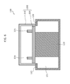
- FIG. 12 schematically shows the clean stocker 100 which exemplifies an automated warehouse according to Embodiment 2 of the present invention. It is noted that the details shared between Embodiments 1 and 2 shall be omitted, and mainly described here are the differences therebetween.
- the load port 120 travels together with the transferring apparatus 130. Moreover, the loading and unloading space 121 of the load port 120 and the holding space 131 of the transferring apparatus 130 are connected with each other. Furthermore, the first shield 140 covers all the load port 120 and the transferring apparatus 130 to close the loading and unloading space 121 and the holding space 131 that are connected with each other.
- the cleaning unit 170 (not shown in FIG. 12 ) then supplies the interconnected loading and unloading space 121 and holding space 131 with CDA to keep the spaces clean.
- the above features allow the reticle taken out of a case at the load port 120 can be transported to the storage rack 110 without moving the reticle out of a clean space. Furthermore, compared with the features described in Embodiment 1, the features in Embodiment 2 make it possible to simplify the structure of each constituent element.
- the first shield 140 does not have to be cylindrical, nor does the transferring apparatus 130 have to be rotated therein either.
- the storage rack 110 may be a rotation rack as a conventional rack is so.
- Embodiments 1 and 2 show as an example the clean stocker 100 to store reticles; however, the present invention shall not be defined as it is. I n other words, the present invention is applicable to automated warehouses for storing any articles to be stored in clean spaces.
- the present invention is beneficial to automated warehouses to store articles in clean spaces.
Landscapes
- Container, Conveyance, Adherence, Positioning, Of Wafer (AREA)
- Warehouses Or Storage Devices (AREA)
Abstract
Description
- The present invention relates to automated warehouses and, in particular, to an automated warehouse which stores articles in a clean space.
- Reticles have been used for manufacturing electronic parts, and are stored in a clean stocker placed in a clean room (See PTL 1 , for example). In the clean stocker, the reticles are taken out of pods for storage, and the ambient inside the clean stocker chassis needs to be kept from volatile impurities.
- A clean stocker disclosed in PTL 1 is equipped with a clean gas supply unit, placed in the upper part of the chassis of the clean stocker, to supply clean gas in order to prevent the volatile impurities from entering the chassis.
- [PTL 1]
Japanese Unexamined Patent Application Publication No.2008-30914 - The above conventional structure, however, requires the clean gas to be supplied to spaces for holding and transporting reticles taken out of pods; specifically, all the spaces inside a pod opener, inside a rotation rack, and between the pod opener and the rotation rack (transportation route for the reticles).
- Here, a chemical filter for the clean gas supply unit is a very expensive expendable, and the life of the chemical filter decreases with an increasing amount of airflow. In other words, in the case where the clean gas is to be supplied to all the above spaces, the chemical filter will have to be replaced in a short period of time and the resulting expenses for the storage will increase. The expenses will further increase in the case where the ambience inside the chassis is to be kept from moisture as well as the volatile impurities (hereinafter referred to as "clean space").
- The present invention is conceived in view of the above problems and aims to provide an object to implement an automated warehouse which is capable of efficiently storing articles in a clean space.
- An automated warehouse according to an aspect of the present invention places an article in a case, and brings in and takes out the article. Specifically, the automated warehouse includes: a storage rack which stores articles including the article; a load port which holds the case and includes a loading and unloading space for loading and unloading the article to and from the held case; a transferring apparatus which includes a holding space for holding the article and transfers the article between the holding space and the storage rack and between the holding space and the case held in the loading and unloading space, the holding space being kept clean; and a first shield which closes the holding space and travels together with the transferring apparatus.
- The above structure allows the holding space alone to be kept clean instead of the entire transportation route of articles. Hence the space to be cleaned needs to be smaller, which contributes to a decrease in storage expenses and efficient storage of articles.
- It is noted that the language "closed" in the Description does not necessarily mean sealing a space as far as impurities are kept from entering the space. In the above example, the first shield may seal the opening for the holding space to keep impurities from entering the holding space. Alternatively, in order to keep impurities from entering the holding space, the first shield may be placed so that there is a narrow clearance between the first shield and the opening for the holding space in order to let the clean gas in the holding space always out from the clearance.
- As an aspect of the present invention, the load port may travel together with the transferring apparatus so that the holding space of the transferring apparatus and the loading and unloading space are connected with each other. The first shield may close to keep clean the loading and unloading space and the holding space connected with each other.
- The above features allow the article taken out of a case at the load port to be transported to the storage rack without moving the article out of a clean space. Hence the space to be cleaned needs to be smaller, and contamination of the article is effectively prevented.
- As another aspect of the present invention, the first shield may include: a cylinder for containing the transferring apparatus rotatable; a first opening formed on a side of the cylinder to face the load port; and a second opening formed on a side of the cylinder to face the storage rack. The transferring apparatus may: rotate to a position where an opening for the holding space faces the first opening, and transfer the article between the holding space and the load port; rotate to a position where the opening for the holding space faces the second opening, and transfer the article between the holding space and the storage rack; and rotate to a position where the opening for the holding space faces an inner sidewall of the cylinder, and travel together with the first shield with the holding space closed.
- According to the above features, the transferring apparatus may rotate inside the first shield so that the opening for the holding space can be exposed only when the apparatus transfers the article and closed when apparatus travels. Hence the space to be cleaned needs to be smaller, and contamination of the article is effectively prevented.
- Moreover, the transferring apparatus may further be capable of vertically traveling inside the cylinder, and prior to the rotation inside the cylinder, the transferring apparatus may ascend or descend to a position where the opening for the holding space does not face either the first opening or the second opening. Such a feature prevents the opening from being exposed while the transferring apparatus is rotating.
- Furthermore, the automated warehouse may include a second shield which is attached to an outer sidewall of the cylinder, travels together with the transferring apparatus and the first shield, and closes a loading and unloading opening on the storage rack for transferring the article when arriving at a position to face the storage rack. The second shield may include a connecting hole for selectively connecting between the second opening on the first shield and a part of the loading and unloading opening on the storage rack, the selective connection being made only to the part through which the article passes. Such features make it possible to limit the area of the loading and unloading opening on the storage rack to a bare minimum, which contributes to more effective prevention of the contamination of the article.
- The present invention allows a holding space alone to be kept clean instead of the entire transportation route of articles. Hence the space to be cleaned needs to be smaller and contamination of the articles is successfully prevented.
-
- [
Fig. 1 ]
FIG. 1 schematically shows a clean stocker according to Embodiment 1 of the present invention. - [
Fig. 2 ]
FIG. 2 shows an exemplary reticle chamber. - [
Fig. 3 ]
FIG. 3 shows how a pod containing a reticle is brought into a load port. - [
Fig. 4 ]
FIG. 4 shows how the pod is vertically separated. - [
Fig. 5 ]
FIG. 5 shows how the pod looks immediately after the reticle has been taken out. - [
Fig. 6 ]
FIG. 6 shows how the pod looks when closed again. - [
Fig. 7 ]
FIG. 7 schematically shows a transferring apparatus. - [
Fig. 8A ]
FIG. 8A shows an exemplary operation of the transferring apparatus inside a shield. - [
Fig. 8B ]
FIG. 8B shows an exemplary operation of the transferring apparatus inside the shield. - [
Fig. 8C ]
FIG. 8C shows an exemplary operation of the transferring apparatus inside the shield. - [
Fig. 8D ]
FIG. 8D shows an exemplary operation of the transferring apparatus inside the shield. - [
Fig. 9 ]
FIG. 9 shows how the transferring apparatus and the load port face each other. - [
Fig. 10 ]
FIG. 10 shows how the transferring apparatus and a reticle chamber face each other. - [
Fig. 11 ]
FI G. 11 shows how a loading and unloading opening appears on the reticle chamber inFIG. 10 . - [
Fig. 12 ]
FIG. 12 schematically shows a clean stocker according to Embodiment 2 of the present invention. - Embodiments of the present invention shall be described hereinafter with reference to the drawings.
-
FIG. 1 schematically shows aclean stocker 100 which exemplifies an automated warehouse according to Embodiment 1 of the present invention. As shown in FI G. 1, theclean stocker 100 mainly includes astorage rack 110, aload port 120, a transferringapparatus 130, afirst shield 140, asecond shield 150, anelevator guide 160, and a cleaning unit (fan filter unit or FFU) 170. Theclean stocker 100 is installed in a clean room of a semiconductor factory or a liquid crystal display factory, and separately stores reticles (articles) for exposure for either semiconductors or liquid crystal substrates, and pods (cases) for containing the reticles. - The storage rack 1 10 stores a reticle taken out of a pod. The structure of the
storage rack 110 shall not be defined in particular. As the example inFIG. 1 shows, thestorage rack 110 includesmultiple reticle chambers 110a. More specifically, thereticle chambers 110a are vertically arranged into a first column (on the left column inFIG. 1 ) and a second column (on the right column inFIG. 1 ) so that the first and second columns are provided around the transferringapparatus 130. -
FIG. 2 shows anexemplary reticle chamber 110a. As shown inFIG. 2 , areticle chamber 110a includes aninner cover 111 formed in a cylinder, and anouter cover 112 which is slightly larger than theinner cover 111 and formed in a cylinder. Theinner cover 111 and theouter cover 112 respectively have anopening 111 1 a and anopening 112a on their sides. - The
inner cover 111 includes racks to place reticles and is fixed so that the opening 1 1 1 a faces the transferringapparatus 130. The inside of theinner cover 111 is kept clean by thecleaning unit 170. Theouter cover 112 covers theinner cover 111 and rotates around theinner cover 111. - When the
outer cover 112 rotates and the openings 1 1 1 a and 112b shift away from each other (on the left inFIG. 2 ), the loading and unloading of the reticles is denied (thereticle chamber 110a closed). When theouter cover 112 rotates and the openings 1 1 1 a and 112a overlap with each other (on the right inFIG. 2 ), the loading and unloading of the reticles is allowed (thereticle chamber 110a open). I n other words, the overlappingopenings 111a and 112b form a loading and unloadingopening 113 on thereticle chamber 110a. - The
load port 120 operates as an interface to bring in and take out a reticle contained in a pod, as well as a pod opener (loading and unloading apparatus) to place and take the reticle in and out of the pod. -
FIGS. 3 to 6 show operations of the load port 1 20 that works as a loading and unloading apparatus. Described with reference toFIGS. 3 to 6 are a structure of theload port 120 and operations to take a reticle out of a pod. It is noted that the process below is reversed to place the reticle in the pod, and the details thereof shall be omitted. - The
load port 120 has a loading and unloadingspace 121 to be used for taking a reticle out of a pod and placing the reticle into the pod. Moreover, the loading and unloadingspace 121 is kept clean by thecleaning unit 170. - As shown in
FIG. 3 , apod 200 includes acover 210 and adoor 220 which are vertically separatable from each other. Moreover, on the top surface of thedoor 220,multiple protrusions 221 are provided to support the reticle. - The
load port 120 includes a lockingpart 122 to lock thecover 210 and aplatform 123 to keep thedoor 220 thereon. It is noted that theplatform 123 operates as an elevator which vertically travels with thedoor 220 kept thereon. - The
load port 120 has an opening on the top thereof. The lockingpart 122 is provided around the opening. Theplatform 123 is placed inside the load port 120 (specifically, in the loading and unloading space 121) to face the opening provided on the top of theload port 120. The top of the load port 1 20 and the platform surface (top surface) of theplatform 123 are to be positioned on the same level when theplatform 123 ascends to the uppermost level. - The
pod 200 is then placed on the platform 1 23 that ascends to the uppermost level. Hence, the opening of theload port 120 is closed by thepod 200. In other words, the loading and unloadingspace 121 is specifically a space which is partitioned by theload port 120 and thecover 210 of thepod 200. - The opening of the
load port 120 is slightly larger than thedoor 220 and smaller than thecover 210. Thus, when theplatform 123 descends with thepod 200 placed thereon, thedoor 220 descends along with theplatform 123 and thecover 210 is locked by the lockingpart 122. Hence, as shown in FI G. 4, thecover 210 and thedoor 220 are vertically separated from each other. - Next, the
reticle 230 placed over thedoor 220 is removed by the transferringapparatus 130, so that theload port 120 looks as shown inFIG. 5 . When theplatform 123 ascends with thedoor 220 placed thereon, thecover 210 is closed again with thedoor 220 as shown in FI G. 6. Theem pty pod 200 shown in FI G. 6 is taken out of theload port 120 by a pod transporting apparatus (not shown) and stored on a pod storage rack (not shown). - The transferring
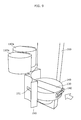
apparatus 130 transfers a reticle between thestorage rack 110 and the load port 1 20.FIG. 7 shows an exemplary structure of the transferringapparatus 130. As shown in FI G. 7, the transferringapparatus 130 includes a holdingspace 131 for holding thereticle 230 therein. Using a slidingfork 133 which ejects from and retracts into the holdingspace 131 via theopening 132, the transferringapparatus 130 transfers thereticle 230 between thestorage rack 110 and the holdingspace 131 and between the holdingspace 131 and thepod 200 that is held in the loading and unloadingspace 121 of theload port 120. Moreover, the holdingspace 131 is kept clean by thecleaning unit 170. - As shown in
FIGS. 8A to 8D , the transferringapparatus 130 is placed inside afirst shield 140. Thefirst shield 140 has acylinder 141 for accommodating thetransferring apparatus 130, and first tothird openings cylinder 141. - The
first opening 142 is formed to face theload port 120. Thesecond opening 143 is formed to face each of thereticle chambers 110a that belong to the first column of thestorage rack 110. Thethird opening 144 is provided to face each of thereticle chambers 110a that belong to the second column of thestorage rack 110. It is noted that the examples inFIGS. 8A to 8D show that thesecond opening 143 is positioned 90 degrees away from thefirst opening 142 in a clockwise direction, and thethird opening 144 is positioned 180 degrees away from thefirst opening 142 in a clockwise direction. - The transferring
apparatus 130 is included in thecylinder 141 to be able to rotate and vertically travel inside thecylinder 141. Together with the transferringapparatus 130, thefirst shield 140 can vertically travel along theelevator guide 160 shown inFIG. 1 . - A
second shield 150, as shown in FI G. 9, is attached to the outer sidewall of thecylinder 141 of thefirst shield 140, and travels together with the transferringapparatus 130 and thefirst shield 140.FIG. 11 shows that thesecond shield 150 travels to a position to face areticle chamber 110a, and closes the loading and unloadingopening 113 for reticles. Thesecond shield 150 includes a connectinghole 151 for selectively connecting between (i) one of the second andthird openings first shield 140 and (ii) a part of the loading and unloadingopening 113 on thereticle chamber 110a. Here, the selective connection is made only to the part through which the reticle passes. - The
cleaning unit 170 may be an FFU. Using a tube and the like, thecleaning unit 170 supplies the inside of the storage rack 1 1 0 and the loading and unloadingspace 121 of theload port 120 with clean dry air (CDA) refined by a DCA refining apparatus provided outside. The DCA keeps clean the inside of thestorage rack 110 and the loading and unloadingspace 121. The CDA is not directly supplied from thecleaning unit 170 to the holdingspace 131 of the transferringapparatus 130; however, when the holdingspace 131 connects to one of thestorage rack 110 and the loading and unloading space 1 21 , the CDA is supplied from thestorage rack 110 and the loading and unloadingspace 121 to the holdingspace 131 to keep the holdingspace 131 clean. I n other words, the keeping clean means that the CDA supplied from the outside is directly or indirectly supplied to each of the units thorough thecleaning unit 170 that operates as an FFU. - With reference to FI GS. 8A to 1 1 , described herewith are exemplary operations of the transferring
apparatus 130 in transferring the reticle in theload port 120 to thestorage rack 110.FIGS. 8A to 8D show exemplary operations of the transferringapparatus 130 inside thefirst shield 140. FI GS. 9 to 11 show positional relationships between the first andsecond shields reticle chamber 110a. It is noted that the process below may be reversed to transfer a reticle on thestorage rack 110 to theload port 120, and the details thereof shall be omitted. - First, as shown in FI G. 9, the transferring
apparatus 130, thefirst shield 140 and the second shield 150 (hereinafter referred to as "the transferringapparatus 130 and the like") are moved along theelevator guide 160 to a position where thefirst opening 142 of thefirst shield 140 faces the load port 120 (not shown inFIG. 9 ). - Next, as shown in FI G. 8A, the transferring
apparatus 130 is rotated inside thecylinder 141 to the position where theopening 132 for the holdingspace 131 faces thefirst opening 142 of thefirst shield 140. Hence, through thefirst opening 142, the loading and unloadingspace 121 of theload port 120 and the holdingspace 131 of the transferringapparatus 130 are connected with each other. The transferringapparatus 130 then obtains the reticle in theload port 120 with the slidingfork 133 and stores the reticle in the holdingspace 131. - Next, as shown in FI G. 8B, the transferring
apparatus 130 is elevated inside thecylinder 141 to the position where theopening 132 for the holdingspace 131 does not face any of theopening 142, theopening 143, or theopening 144. Hence, theopening 132 for the holdingspace 131 is closed with the inner sidewall of thefirst shield 140. - Then, as shown in FI G. 8C, the transferring
apparatus 130 inFIG. 8B is rotated inside thecylinder 141 as much as 90 degrees clockwise. It is noted that, prior to the rotation, the transferringapparatus 130 is elevated so that theopening 132 for the holdingspace 131 is kept closed with the inner sidewall of thecylinder 141. Such an operation contributes to preventing the CDA supplied from thecleaning unit 170 from leaking out of the holdingspace 131. - Next, as shown in
FIG. 10 , the transferringapparatus 130 and the like are moved along theelevator guide 160 to a position wheresecond opening 143 of thefirst shield 140 faces areticle chamber 110a. More specifically, the connectinghole 151 on thesecond shield 150 is to face a position of a rack, included in thereticle chamber 110a, on which the reticle to be placed. - Then, as shown in
FIG. 1 1 , the outer cover 1 1 2 of thereticle chamber 110a is rotated so that theopenings opening 113. Here, the loading and unloadingopening 113 on thereticle chamber 110a is closed with thesecond shield 150 except the position of the connectinghole 151, which contributes to reducing the amount of the CDA to leak out of thereticle chamber 110a. - Next, as shown in FI G. 8D, the transferring
apparatus 130 is lowered inside thecylinder 141 to the position where theopening 132 for the holdingspace 131 faces thesecond opening 143 of thefirst shield 140. Hence, thereticle chamber 110a connects to the holdingspace 131 of the transferringapparatus 130 through thefirst opening 142 and the connectinghole 151. The transferringapparatus 130 then transfers the reticle from the holdingspace 131 to thestorage rack 110, using the slidingfork 133. - Thanks to the above features, it is the inside of the
reticle chamber 110a, the loading and unloadingspace 121 of theload port 120 and the holdingspace 131 of the transferringapparatus 130 alone that thecleaning unit 170 has to keep clean. I n other words, the features eliminates the need of keeping the entire transportation route of reticles as a conventional clean stocker has to do so, which contributes to reducing the space to be cleaned. The resulting smaller cleaning space allows storage expenses to decrease and contributes to efficient prevention of contamination of the reticles. - It is noted that the above description is one example, and therefore shall not be defined as it is. For example, the order of the each of the operations may partly be changed. Specifically, the transferring
apparatus 130 and the like may be first elevated to the position of thereticle chamber 110a, and then the transferringapparatus 130 inside thefirst shield 140 in FI G. 8B may be rotated as shown inFIG. 8C . Moreover, as an example, the transferringapparatus 130 is elevated inside thecylinder 141 as shown inFIG. 8B and the transferringapparatus 130 is lowered in thecylinder 141 as shown inFIG. 8D ; instead, transferringapparatus 130 may be lowered prior to the rotation and elevated after the rotation. -
FIG. 12 schematically shows theclean stocker 100 which exemplifies an automated warehouse according to Embodiment 2 of the present invention. It is noted that the details shared between Embodiments 1 and 2 shall be omitted, and mainly described here are the differences therebetween. - I n the
clean stocker 100 shown inFIG. 12 , theload port 120 travels together with the transferringapparatus 130. Moreover, the loading and unloadingspace 121 of theload port 120 and the holdingspace 131 of the transferringapparatus 130 are connected with each other. Furthermore, thefirst shield 140 covers all theload port 120 and the transferringapparatus 130 to close the loading and unloadingspace 121 and the holdingspace 131 that are connected with each other. The cleaning unit 170 (not shown inFIG. 12 ) then supplies the interconnected loading and unloadingspace 121 and holdingspace 131 with CDA to keep the spaces clean. - The above features allow the reticle taken out of a case at the
load port 120 can be transported to thestorage rack 110 without moving the reticle out of a clean space. Furthermore, compared with the features described in Embodiment 1, the features in Embodiment 2 make it possible to simplify the structure of each constituent element. In other words, thefirst shield 140 does not have to be cylindrical, nor does the transferringapparatus 130 have to be rotated therein either. In addition, thestorage rack 110 may be a rotation rack as a conventional rack is so. - It is noted that Embodiments 1 and 2 show as an example the
clean stocker 100 to store reticles; however, the present invention shall not be defined as it is. I n other words, the present invention is applicable to automated warehouses for storing any articles to be stored in clean spaces. - Although only some exemplary embodiments of this invention have been described in detail above, those skilled in the art will readily appreciate that many modifications are possible in the exemplary embodiments without materially departing from the novel teachings and advantages of this invention. Accordingly, all such modifications are intended to be included within the scope of this invention.
- The present invention is beneficial to automated warehouses to store articles in clean spaces.
-
- 100
- Clean stocker
- 110
- Storage rack
- 110a
- Reticle chamber
- 111
- Inner cover
- 111a, 112a, and 132
- Opening
- 112
- Outer cover
- 113
- Loading and unloading opening
- 120
- Load port
- 121
- Loading and unloading space
- 122
- Locking part
- 123
- Platform
- 130
- Transferring apparatus
- 131
- Holding space
- 133
- Sliding fork
- 140
- First shield
- 141
- Cylinder
- 142
- First opening
- 142
- Second opening
- 144
- Third opening
- 150
- Second shield
- 151
- Connecting hole
- 160
- Elevator guide
- 170
- Cleaning unit
- 200
- Pod
- 210
- Cover
- 220
- Door
- 221
- Protrusion
- 230
- Reticle
Claims (5)
- An automated warehouse which places an article in a case, and brings in and takes out the article, the automated warehouse comprising:a storage rack which stores articles including the article;a load port which holds the case and includes a loading and unloading space for loading and unloading the article to and from the held case;a transferring apparatus which includes a holding space for holding the article and transfers the article between the holding space and the storage rack and between the holding space and the case held in the loading and unloading space, the holding space being kept clean; anda first shield which closes the holding space and travels together with the transferring apparatus.
- The automated warehouse according to Claim 1,
wherein the load port travels together with the transferring apparatus so that the holding space of the transferring apparatus and the loading and unloading space are connected with each other, and
the first shield closes to keep clean the loading and unloading space and the holding space connected with each other. - The automated warehouse according to Claim 1,
wherein the first shield includes:a cylinder for containing the transferring apparatus rotatable;a first opening formed on a side of the cylinder to face the load port; anda second opening formed on a side of the cylinder to face the storage rack, andthe transferring apparatus:rotates to a position where an opening for the holding space faces the first opening, and transfers the article between the holding space and the load port;rotates to a position where the opening for the holding space faces the second opening, and transfers the article between the holding space and the storage rack; androtates to a position where the opening for the holding space faces an inner sidewall of the cylinder, and travels together with the first shield with the holding space closed. - The automated warehouse according to Claim 3,
wherein the transferring apparatus is further capable of vertically traveling inside the cylinder, and
prior to the rotation inside the cylinder, the transferring apparatus ascends or descends to a position where the opening for the holding space does not face either the first opening or the second opening. - The automated warehouse according to one of Claims 3 and 4, further comprising
a second shield which is attached to an outer sidewall of the cylinder, travels together with the transferring apparatus and the first shield, and closes a loading and unloading opening on the storage rack for transferring the article when arriving at a position to face the storage rack,
wherein the second shield includes a connecting hole for selectively connecting between the second opening on the first shield and a part of the loading and unloading opening on the storage rack, the selective connection being made only to the part through which the article passes.
Applications Claiming Priority (2)
| Application Number | Priority Date | Filing Date | Title |
|---|---|---|---|
| JP2011103242 | 2011-05-02 | ||
| PCT/JP2012/001733 WO2012150644A1 (en) | 2011-05-02 | 2012-03-13 | Automated warehouse |
Publications (3)
| Publication Number | Publication Date |
|---|---|
| EP2706563A1 true EP2706563A1 (en) | 2014-03-12 |
| EP2706563A4 EP2706563A4 (en) | 2014-12-03 |
| EP2706563B1 EP2706563B1 (en) | 2015-09-16 |
Family
ID=47107837
Family Applications (1)
| Application Number | Title | Priority Date | Filing Date |
|---|---|---|---|
| EP12779503.7A Active EP2706563B1 (en) | 2011-05-02 | 2012-03-13 | Automated warehouse |
Country Status (5)
| Country | Link |
|---|---|
| US (1) | US8956098B2 (en) |
| EP (1) | EP2706563B1 (en) |
| JP (1) | JP5673806B2 (en) |
| TW (1) | TWI502674B (en) |
| WO (1) | WO2012150644A1 (en) |
Families Citing this family (1)
| Publication number | Priority date | Publication date | Assignee | Title |
|---|---|---|---|---|
| JP6747511B2 (en) * | 2016-10-07 | 2020-08-26 | 村田機械株式会社 | Conveying device and conveying method |
Family Cites Families (30)
| Publication number | Priority date | Publication date | Assignee | Title |
|---|---|---|---|---|
| ATE129359T1 (en) * | 1992-08-04 | 1995-11-15 | Ibm | DISTRIBUTION DEVICE WITH GAS SUPPLY-DELIVERY DEVICE FOR HANDLING AND STORING SEALABLE PORTABLE PRESSURIZED CONTAINERS. |
| JPH0750334A (en) * | 1993-08-03 | 1995-02-21 | Dainippon Screen Mfg Co Ltd | Substrate treatment device |
| US5607275A (en) * | 1993-08-26 | 1997-03-04 | Exabyte Corporation | Cartridge library and method of operation |
| DE69403890T2 (en) * | 1994-01-14 | 1998-01-08 | International Business Machines Corp., Armonk, N.Y. | Assembly / disassembly device for sealable pressurized transport containers |
| US5830272A (en) * | 1995-11-07 | 1998-11-03 | Sputtered Films, Inc. | System for and method of providing a controlled deposition on wafers |
| US5752796A (en) * | 1996-01-24 | 1998-05-19 | Muka; Richard S. | Vacuum integrated SMIF system |
| US6082949A (en) * | 1996-10-11 | 2000-07-04 | Asyst Technologies, Inc. | Load port opener |
| JPH10157847A (en) * | 1996-11-29 | 1998-06-16 | Canon Sales Co Inc | Substrate transfer robot apparatus, substrate processing apparatus using the same, and semiconductor manufacturing apparatus |
| JPH1124750A (en) * | 1997-07-08 | 1999-01-29 | Shinko Electric Co Ltd | Unmanned transfer device |
| US6283692B1 (en) * | 1998-12-01 | 2001-09-04 | Applied Materials, Inc. | Apparatus for storing and moving a cassette |
| US6481558B1 (en) * | 1998-12-18 | 2002-11-19 | Asyst Technologies, Inc. | Integrated load port-conveyor transfer system |
| US6506009B1 (en) * | 2000-03-16 | 2003-01-14 | Applied Materials, Inc. | Apparatus for storing and moving a cassette |
| US6619903B2 (en) * | 2001-08-10 | 2003-09-16 | Glenn M. Friedman | System and method for reticle protection and transport |
| JP2003188229A (en) * | 2001-12-18 | 2003-07-04 | Hitachi Kasado Eng Co Ltd | Wafer manufacturing system and wafer manufacturing method |
| CH695872A5 (en) * | 2002-07-29 | 2006-09-29 | Brooks Pri Automation Switzerl | Reticle handling device. |
| US6955197B2 (en) * | 2002-08-31 | 2005-10-18 | Applied Materials, Inc. | Substrate carrier having door latching and substrate clamping mechanisms |
| JP4283559B2 (en) * | 2003-02-24 | 2009-06-24 | 東京エレクトロン株式会社 | Conveying apparatus, vacuum processing apparatus, and atmospheric pressure conveying apparatus |
| US7458763B2 (en) * | 2003-11-10 | 2008-12-02 | Blueshift Technologies, Inc. | Mid-entry load lock for semiconductor handling system |
| TWI367192B (en) * | 2003-11-13 | 2012-07-01 | Applied Materials Inc | Calibration of high speed loader to substrate transport system |
| CN101048327B (en) * | 2004-10-25 | 2012-06-20 | 东京毅力科创株式会社 | Carrying system, substrate treating device |
| US7396412B2 (en) * | 2004-12-22 | 2008-07-08 | Sokudo Co., Ltd. | Coat/develop module with shared dispense |
| US7410340B2 (en) * | 2005-02-24 | 2008-08-12 | Asyst Technologies, Inc. | Direct tool loading |
| US7661919B2 (en) * | 2005-09-28 | 2010-02-16 | Muratec Automation Co., Ltd. | Discontinuous conveyor system |
| US7896602B2 (en) | 2006-06-09 | 2011-03-01 | Lutz Rebstock | Workpiece stocker with circular configuration |
| JP4215079B2 (en) * | 2006-07-31 | 2009-01-28 | 村田機械株式会社 | Clean stocker and article storage method |
| JP4904995B2 (en) * | 2006-08-28 | 2012-03-28 | シンフォニアテクノロジー株式会社 | Load port device |
| US8128333B2 (en) * | 2006-11-27 | 2012-03-06 | Hitachi Kokusai Electric Inc. | Substrate processing apparatus and manufacturing method for semiconductor devices |
| US7694688B2 (en) * | 2007-01-05 | 2010-04-13 | Applied Materials, Inc. | Wet clean system design |
| TW200946422A (en) * | 2008-03-13 | 2009-11-16 | Fortrend Engineering Corp | Bare reticle storage chamber and stocker |
| US8562272B2 (en) * | 2010-02-16 | 2013-10-22 | Lam Research Corporation | Substrate load and unload mechanisms for high throughput |
-
2012
- 2012-03-13 US US14/114,782 patent/US8956098B2/en active Active
- 2012-03-13 JP JP2013513063A patent/JP5673806B2/en active Active
- 2012-03-13 WO PCT/JP2012/001733 patent/WO2012150644A1/en not_active Ceased
- 2012-03-13 EP EP12779503.7A patent/EP2706563B1/en active Active
- 2012-05-01 TW TW101115446A patent/TWI502674B/en active
Non-Patent Citations (2)
| Title |
|---|
| No further relevant documents disclosed * |
| See also references of WO2012150644A1 * |
Also Published As
| Publication number | Publication date |
|---|---|
| EP2706563B1 (en) | 2015-09-16 |
| EP2706563A4 (en) | 2014-12-03 |
| US8956098B2 (en) | 2015-02-17 |
| TW201249728A (en) | 2012-12-16 |
| TWI502674B (en) | 2015-10-01 |
| WO2012150644A1 (en) | 2012-11-08 |
| US20140056671A1 (en) | 2014-02-27 |
| JP5673806B2 (en) | 2015-02-18 |
| JPWO2012150644A1 (en) | 2014-07-28 |
Similar Documents
| Publication | Publication Date | Title |
|---|---|---|
| TWI688034B (en) | Loading port and atmosphere replacement method of loading port | |
| TWI780030B (en) | Method and system for forming a clean environment for semiconductor substrates with low humidity level | |
| EP2432009B1 (en) | Purging apparatus and purging method | |
| CN101118375B (en) | Clean stocker and method of storing articles | |
| US11573244B2 (en) | Pipettor system | |
| CN102820247B (en) | The opening and closing device of substrate transport box, the opening and closing device of lid and semiconductor-fabricating device | |
| EP2863423B1 (en) | Lid opening/closing device | |
| US20150179489A1 (en) | Substrate Processing Module, Substrate Processing Apparatus Including the same, and Substrate Transferring Method | |
| KR20150041587A (en) | Chemical liquid container replacement device, container mounting module, chemical liquid container replacement method, and substrate processing apparatus | |
| JP2015076472A (en) | Chemical container replacement device, container placement module, and chemical container replacement method | |
| US10090182B2 (en) | Load port device and cleaning gas introducing method into a container on a load port | |
| JP2015141916A (en) | Substrate heat treatment apparatus and method for installing substrate heat treatment apparatus | |
| JP2021077691A (en) | Substrate processing apparatus and substrate housing container storage method | |
| KR20090003227A (en) | Wafer storage and its storage control method | |
| JP5987808B2 (en) | Substrate processing equipment | |
| EP2706563B1 (en) | Automated warehouse | |
| JP5164416B2 (en) | Substrate processing apparatus, storage container transport method, and semiconductor device manufacturing method | |
| CN102386053A (en) | Substrate processing apparatus and method of manufacturing semiconductor device | |
| KR100236272B1 (en) | Cleanroom Storage | |
| JP5279576B2 (en) | Substrate processing equipment | |
| US9472430B2 (en) | Substrate storage container and exposure apparatus | |
| JP5882600B2 (en) | Substrate processing apparatus and semiconductor device manufacturing method | |
| JP6899904B2 (en) | Board transfer device and board transfer method | |
| KR101085454B1 (en) | Hermetic Cassette Transfer System | |
| JP2013051267A (en) | Tank carrier and substrate processing apparatus |
Legal Events
| Date | Code | Title | Description |
|---|---|---|---|
| PUAI | Public reference made under article 153(3) epc to a published international application that has entered the european phase |
Free format text: ORIGINAL CODE: 0009012 |
|
| 17P | Request for examination filed |
Effective date: 20131023 |
|
| AK | Designated contracting states |
Kind code of ref document: A1 Designated state(s): AL AT BE BG CH CY CZ DE DK EE ES FI FR GB GR HR HU IE IS IT LI LT LU LV MC MK MT NL NO PL PT RO RS SE SI SK SM TR |
|
| DAX | Request for extension of the european patent (deleted) | ||
| REG | Reference to a national code |
Ref country code: DE Ref legal event code: R079 Ref document number: 602012010777 Country of ref document: DE Free format text: PREVIOUS MAIN CLASS: H01L0021673000 Ipc: H01L0021677000 |
|
| A4 | Supplementary search report drawn up and despatched |
Effective date: 20141105 |
|
| RIC1 | Information provided on ipc code assigned before grant |
Ipc: H01L 21/677 20060101AFI20141030BHEP |
|
| GRAP | Despatch of communication of intention to grant a patent |
Free format text: ORIGINAL CODE: EPIDOSNIGR1 |
|
| INTG | Intention to grant announced |
Effective date: 20150331 |
|
| GRAS | Grant fee paid |
Free format text: ORIGINAL CODE: EPIDOSNIGR3 |
|
| GRAA | (expected) grant |
Free format text: ORIGINAL CODE: 0009210 |
|
| AK | Designated contracting states |
Kind code of ref document: B1 Designated state(s): AL AT BE BG CH CY CZ DE DK EE ES FI FR GB GR HR HU IE IS IT LI LT LU LV MC MK MT NL NO PL PT RO RS SE SI SK SM TR |
|
| REG | Reference to a national code |
Ref country code: GB Ref legal event code: FG4D |
|
| REG | Reference to a national code |
Ref country code: CH Ref legal event code: EP |
|
| REG | Reference to a national code |
Ref country code: IE Ref legal event code: FG4D |
|
| REG | Reference to a national code |
Ref country code: AT Ref legal event code: REF Ref document number: 750393 Country of ref document: AT Kind code of ref document: T Effective date: 20151015 |
|
| REG | Reference to a national code |
Ref country code: DE Ref legal event code: R096 Ref document number: 602012010777 Country of ref document: DE |
|
| REG | Reference to a national code |
Ref country code: NL Ref legal event code: MP Effective date: 20150916 |
|
| PG25 | Lapsed in a contracting state [announced via postgrant information from national office to epo] |
Ref country code: LT Free format text: LAPSE BECAUSE OF FAILURE TO SUBMIT A TRANSLATION OF THE DESCRIPTION OR TO PAY THE FEE WITHIN THE PRESCRIBED TIME-LIMIT Effective date: 20150916 Ref country code: FI Free format text: LAPSE BECAUSE OF FAILURE TO SUBMIT A TRANSLATION OF THE DESCRIPTION OR TO PAY THE FEE WITHIN THE PRESCRIBED TIME-LIMIT Effective date: 20150916 Ref country code: NO Free format text: LAPSE BECAUSE OF FAILURE TO SUBMIT A TRANSLATION OF THE DESCRIPTION OR TO PAY THE FEE WITHIN THE PRESCRIBED TIME-LIMIT Effective date: 20151216 Ref country code: LV Free format text: LAPSE BECAUSE OF FAILURE TO SUBMIT A TRANSLATION OF THE DESCRIPTION OR TO PAY THE FEE WITHIN THE PRESCRIBED TIME-LIMIT Effective date: 20150916 Ref country code: GR Free format text: LAPSE BECAUSE OF FAILURE TO SUBMIT A TRANSLATION OF THE DESCRIPTION OR TO PAY THE FEE WITHIN THE PRESCRIBED TIME-LIMIT Effective date: 20151217 |
|
| REG | Reference to a national code |
Ref country code: LT Ref legal event code: MG4D |
|
| REG | Reference to a national code |
Ref country code: AT Ref legal event code: MK05 Ref document number: 750393 Country of ref document: AT Kind code of ref document: T Effective date: 20150916 |
|
| PG25 | Lapsed in a contracting state [announced via postgrant information from national office to epo] |
Ref country code: HR Free format text: LAPSE BECAUSE OF FAILURE TO SUBMIT A TRANSLATION OF THE DESCRIPTION OR TO PAY THE FEE WITHIN THE PRESCRIBED TIME-LIMIT Effective date: 20150916 Ref country code: RS Free format text: LAPSE BECAUSE OF FAILURE TO SUBMIT A TRANSLATION OF THE DESCRIPTION OR TO PAY THE FEE WITHIN THE PRESCRIBED TIME-LIMIT Effective date: 20150916 Ref country code: SE Free format text: LAPSE BECAUSE OF FAILURE TO SUBMIT A TRANSLATION OF THE DESCRIPTION OR TO PAY THE FEE WITHIN THE PRESCRIBED TIME-LIMIT Effective date: 20150916 |
|
| PG25 | Lapsed in a contracting state [announced via postgrant information from national office to epo] |
Ref country code: NL Free format text: LAPSE BECAUSE OF FAILURE TO SUBMIT A TRANSLATION OF THE DESCRIPTION OR TO PAY THE FEE WITHIN THE PRESCRIBED TIME-LIMIT Effective date: 20150916 |
|
| PG25 | Lapsed in a contracting state [announced via postgrant information from national office to epo] |
Ref country code: EE Free format text: LAPSE BECAUSE OF FAILURE TO SUBMIT A TRANSLATION OF THE DESCRIPTION OR TO PAY THE FEE WITHIN THE PRESCRIBED TIME-LIMIT Effective date: 20150916 Ref country code: SK Free format text: LAPSE BECAUSE OF FAILURE TO SUBMIT A TRANSLATION OF THE DESCRIPTION OR TO PAY THE FEE WITHIN THE PRESCRIBED TIME-LIMIT Effective date: 20150916 Ref country code: IS Free format text: LAPSE BECAUSE OF FAILURE TO SUBMIT A TRANSLATION OF THE DESCRIPTION OR TO PAY THE FEE WITHIN THE PRESCRIBED TIME-LIMIT Effective date: 20160116 Ref country code: CZ Free format text: LAPSE BECAUSE OF FAILURE TO SUBMIT A TRANSLATION OF THE DESCRIPTION OR TO PAY THE FEE WITHIN THE PRESCRIBED TIME-LIMIT Effective date: 20150916 Ref country code: ES Free format text: LAPSE BECAUSE OF FAILURE TO SUBMIT A TRANSLATION OF THE DESCRIPTION OR TO PAY THE FEE WITHIN THE PRESCRIBED TIME-LIMIT Effective date: 20150916 Ref country code: IT Free format text: LAPSE BECAUSE OF FAILURE TO SUBMIT A TRANSLATION OF THE DESCRIPTION OR TO PAY THE FEE WITHIN THE PRESCRIBED TIME-LIMIT Effective date: 20150916 |
|
| PG25 | Lapsed in a contracting state [announced via postgrant information from national office to epo] |
Ref country code: PT Free format text: LAPSE BECAUSE OF FAILURE TO SUBMIT A TRANSLATION OF THE DESCRIPTION OR TO PAY THE FEE WITHIN THE PRESCRIBED TIME-LIMIT Effective date: 20160118 Ref country code: AT Free format text: LAPSE BECAUSE OF FAILURE TO SUBMIT A TRANSLATION OF THE DESCRIPTION OR TO PAY THE FEE WITHIN THE PRESCRIBED TIME-LIMIT Effective date: 20150916 Ref country code: RO Free format text: LAPSE BECAUSE OF FAILURE TO SUBMIT A TRANSLATION OF THE DESCRIPTION OR TO PAY THE FEE WITHIN THE PRESCRIBED TIME-LIMIT Effective date: 20150916 Ref country code: PL Free format text: LAPSE BECAUSE OF FAILURE TO SUBMIT A TRANSLATION OF THE DESCRIPTION OR TO PAY THE FEE WITHIN THE PRESCRIBED TIME-LIMIT Effective date: 20150916 |
|
| REG | Reference to a national code |
Ref country code: DE Ref legal event code: R097 Ref document number: 602012010777 Country of ref document: DE |
|
| PLBE | No opposition filed within time limit |
Free format text: ORIGINAL CODE: 0009261 |
|
| STAA | Information on the status of an ep patent application or granted ep patent |
Free format text: STATUS: NO OPPOSITION FILED WITHIN TIME LIMIT |
|
| 26N | No opposition filed |
Effective date: 20160617 |
|
| PG25 | Lapsed in a contracting state [announced via postgrant information from national office to epo] |
Ref country code: DK Free format text: LAPSE BECAUSE OF FAILURE TO SUBMIT A TRANSLATION OF THE DESCRIPTION OR TO PAY THE FEE WITHIN THE PRESCRIBED TIME-LIMIT Effective date: 20150916 Ref country code: BE Free format text: LAPSE BECAUSE OF NON-PAYMENT OF DUE FEES Effective date: 20160331 |
|
| PG25 | Lapsed in a contracting state [announced via postgrant information from national office to epo] |
Ref country code: MC Free format text: LAPSE BECAUSE OF FAILURE TO SUBMIT A TRANSLATION OF THE DESCRIPTION OR TO PAY THE FEE WITHIN THE PRESCRIBED TIME-LIMIT Effective date: 20150916 Ref country code: LU Free format text: LAPSE BECAUSE OF FAILURE TO SUBMIT A TRANSLATION OF THE DESCRIPTION OR TO PAY THE FEE WITHIN THE PRESCRIBED TIME-LIMIT Effective date: 20160313 |
|
| REG | Reference to a national code |
Ref country code: CH Ref legal event code: PL |
|
| GBPC | Gb: european patent ceased through non-payment of renewal fee |
Effective date: 20160313 |
|
| PG25 | Lapsed in a contracting state [announced via postgrant information from national office to epo] |
Ref country code: SI Free format text: LAPSE BECAUSE OF FAILURE TO SUBMIT A TRANSLATION OF THE DESCRIPTION OR TO PAY THE FEE WITHIN THE PRESCRIBED TIME-LIMIT Effective date: 20150916 |
|
| PG25 | Lapsed in a contracting state [announced via postgrant information from national office to epo] |
Ref country code: BE Free format text: LAPSE BECAUSE OF FAILURE TO SUBMIT A TRANSLATION OF THE DESCRIPTION OR TO PAY THE FEE WITHIN THE PRESCRIBED TIME-LIMIT Effective date: 20150916 |
|
| REG | Reference to a national code |
Ref country code: FR Ref legal event code: ST Effective date: 20161130 |
|
| PG25 | Lapsed in a contracting state [announced via postgrant information from national office to epo] |
Ref country code: LI Free format text: LAPSE BECAUSE OF NON-PAYMENT OF DUE FEES Effective date: 20160331 Ref country code: CH Free format text: LAPSE BECAUSE OF NON-PAYMENT OF DUE FEES Effective date: 20160331 Ref country code: FR Free format text: LAPSE BECAUSE OF NON-PAYMENT OF DUE FEES Effective date: 20160331 Ref country code: GB Free format text: LAPSE BECAUSE OF NON-PAYMENT OF DUE FEES Effective date: 20160313 |
|
| PG25 | Lapsed in a contracting state [announced via postgrant information from national office to epo] |
Ref country code: MT Free format text: LAPSE BECAUSE OF FAILURE TO SUBMIT A TRANSLATION OF THE DESCRIPTION OR TO PAY THE FEE WITHIN THE PRESCRIBED TIME-LIMIT Effective date: 20150916 |
|
| PG25 | Lapsed in a contracting state [announced via postgrant information from national office to epo] |
Ref country code: CY Free format text: LAPSE BECAUSE OF FAILURE TO SUBMIT A TRANSLATION OF THE DESCRIPTION OR TO PAY THE FEE WITHIN THE PRESCRIBED TIME-LIMIT Effective date: 20150916 Ref country code: HU Free format text: LAPSE BECAUSE OF FAILURE TO SUBMIT A TRANSLATION OF THE DESCRIPTION OR TO PAY THE FEE WITHIN THE PRESCRIBED TIME-LIMIT; INVALID AB INITIO Effective date: 20120313 Ref country code: SM Free format text: LAPSE BECAUSE OF FAILURE TO SUBMIT A TRANSLATION OF THE DESCRIPTION OR TO PAY THE FEE WITHIN THE PRESCRIBED TIME-LIMIT Effective date: 20150916 |
|
| PG25 | Lapsed in a contracting state [announced via postgrant information from national office to epo] |
Ref country code: TR Free format text: LAPSE BECAUSE OF FAILURE TO SUBMIT A TRANSLATION OF THE DESCRIPTION OR TO PAY THE FEE WITHIN THE PRESCRIBED TIME-LIMIT Effective date: 20150916 Ref country code: MT Free format text: LAPSE BECAUSE OF FAILURE TO SUBMIT A TRANSLATION OF THE DESCRIPTION OR TO PAY THE FEE WITHIN THE PRESCRIBED TIME-LIMIT Effective date: 20160331 Ref country code: MK Free format text: LAPSE BECAUSE OF FAILURE TO SUBMIT A TRANSLATION OF THE DESCRIPTION OR TO PAY THE FEE WITHIN THE PRESCRIBED TIME-LIMIT Effective date: 20150916 |
|
| PG25 | Lapsed in a contracting state [announced via postgrant information from national office to epo] |
Ref country code: BG Free format text: LAPSE BECAUSE OF FAILURE TO SUBMIT A TRANSLATION OF THE DESCRIPTION OR TO PAY THE FEE WITHIN THE PRESCRIBED TIME-LIMIT Effective date: 20150916 |
|
| PG25 | Lapsed in a contracting state [announced via postgrant information from national office to epo] |
Ref country code: AL Free format text: LAPSE BECAUSE OF FAILURE TO SUBMIT A TRANSLATION OF THE DESCRIPTION OR TO PAY THE FEE WITHIN THE PRESCRIBED TIME-LIMIT Effective date: 20150916 |
|
| PGFP | Annual fee paid to national office [announced via postgrant information from national office to epo] |
Ref country code: IE Payment date: 20250220 Year of fee payment: 14 |
|
| REG | Reference to a national code |
Ref country code: DE Ref legal event code: R079 Ref document number: 602012010777 Country of ref document: DE Free format text: PREVIOUS MAIN CLASS: H01L0021677000 Ipc: H10P0072300000 |
|
| PGFP | Annual fee paid to national office [announced via postgrant information from national office to epo] |
Ref country code: DE Payment date: 20260219 Year of fee payment: 15 |