EP2704530A2 - Modulares, mehrkanaliges Verbindersystem und Verfahren - Google Patents
Modulares, mehrkanaliges Verbindersystem und Verfahren Download PDFInfo
- Publication number
- EP2704530A2 EP2704530A2 EP20130181698 EP13181698A EP2704530A2 EP 2704530 A2 EP2704530 A2 EP 2704530A2 EP 20130181698 EP20130181698 EP 20130181698 EP 13181698 A EP13181698 A EP 13181698A EP 2704530 A2 EP2704530 A2 EP 2704530A2
- Authority
- EP
- European Patent Office
- Prior art keywords
- port
- electrical contacts
- substrate
- connection
- substrates
- Prior art date
- Legal status (The legal status is an assumption and is not a legal conclusion. Google has not performed a legal analysis and makes no representation as to the accuracy of the status listed.)
- Withdrawn
Links
- 238000000034 method Methods 0.000 title claims abstract description 14
- 239000000758 substrate Substances 0.000 claims abstract description 362
- 239000007787 solid Substances 0.000 claims description 80
- 230000008878 coupling Effects 0.000 claims description 44
- 238000010168 coupling process Methods 0.000 claims description 44
- 238000005859 coupling reaction Methods 0.000 claims description 44
- 239000000463 material Substances 0.000 description 3
- 239000003086 colorant Substances 0.000 description 2
- 238000010586 diagram Methods 0.000 description 2
- 230000005693 optoelectronics Effects 0.000 description 2
- 239000002131 composite material Substances 0.000 description 1
- 150000001875 compounds Chemical class 0.000 description 1
- 239000002184 metal Substances 0.000 description 1
- 238000012986 modification Methods 0.000 description 1
- 230000004048 modification Effects 0.000 description 1
- 229920000642 polymer Polymers 0.000 description 1
- 230000005855 radiation Effects 0.000 description 1
- 239000004065 semiconductor Substances 0.000 description 1
- 238000001228 spectrum Methods 0.000 description 1
Images




Classifications
-
- H—ELECTRICITY
- H05—ELECTRIC TECHNIQUES NOT OTHERWISE PROVIDED FOR
- H05B—ELECTRIC HEATING; ELECTRIC LIGHT SOURCES NOT OTHERWISE PROVIDED FOR; CIRCUIT ARRANGEMENTS FOR ELECTRIC LIGHT SOURCES, IN GENERAL
- H05B45/00—Circuit arrangements for operating light-emitting diodes [LED]
- H05B45/30—Driver circuits
- H05B45/395—Linear regulators
-
- F—MECHANICAL ENGINEERING; LIGHTING; HEATING; WEAPONS; BLASTING
- F21—LIGHTING
- F21V—FUNCTIONAL FEATURES OR DETAILS OF LIGHTING DEVICES OR SYSTEMS THEREOF; STRUCTURAL COMBINATIONS OF LIGHTING DEVICES WITH OTHER ARTICLES, NOT OTHERWISE PROVIDED FOR
- F21V19/00—Fastening of light sources or lamp holders
- F21V19/001—Fastening of light sources or lamp holders the light sources being semiconductors devices, e.g. LEDs
-
- F—MECHANICAL ENGINEERING; LIGHTING; HEATING; WEAPONS; BLASTING
- F21—LIGHTING
- F21V—FUNCTIONAL FEATURES OR DETAILS OF LIGHTING DEVICES OR SYSTEMS THEREOF; STRUCTURAL COMBINATIONS OF LIGHTING DEVICES WITH OTHER ARTICLES, NOT OTHERWISE PROVIDED FOR
- F21V19/00—Fastening of light sources or lamp holders
-
- F—MECHANICAL ENGINEERING; LIGHTING; HEATING; WEAPONS; BLASTING
- F21—LIGHTING
- F21V—FUNCTIONAL FEATURES OR DETAILS OF LIGHTING DEVICES OR SYSTEMS THEREOF; STRUCTURAL COMBINATIONS OF LIGHTING DEVICES WITH OTHER ARTICLES, NOT OTHERWISE PROVIDED FOR
- F21V23/00—Arrangement of electric circuit elements in or on lighting devices
- F21V23/06—Arrangement of electric circuit elements in or on lighting devices the elements being coupling devices, e.g. connectors
-
- Y—GENERAL TAGGING OF NEW TECHNOLOGICAL DEVELOPMENTS; GENERAL TAGGING OF CROSS-SECTIONAL TECHNOLOGIES SPANNING OVER SEVERAL SECTIONS OF THE IPC; TECHNICAL SUBJECTS COVERED BY FORMER USPC CROSS-REFERENCE ART COLLECTIONS [XRACs] AND DIGESTS
- Y02—TECHNOLOGIES OR APPLICATIONS FOR MITIGATION OR ADAPTATION AGAINST CLIMATE CHANGE
- Y02B—CLIMATE CHANGE MITIGATION TECHNOLOGIES RELATED TO BUILDINGS, e.g. HOUSING, HOUSE APPLIANCES OR RELATED END-USER APPLICATIONS
- Y02B20/00—Energy efficient lighting technologies, e.g. halogen lamps or gas discharge lamps
- Y02B20/30—Semiconductor lamps, e.g. solid state lamps [SSL] light emitting diodes [LED] or organic LED [OLED]
-
- Y—GENERAL TAGGING OF NEW TECHNOLOGICAL DEVELOPMENTS; GENERAL TAGGING OF CROSS-SECTIONAL TECHNOLOGIES SPANNING OVER SEVERAL SECTIONS OF THE IPC; TECHNICAL SUBJECTS COVERED BY FORMER USPC CROSS-REFERENCE ART COLLECTIONS [XRACs] AND DIGESTS
- Y10—TECHNICAL SUBJECTS COVERED BY FORMER USPC
- Y10T—TECHNICAL SUBJECTS COVERED BY FORMER US CLASSIFICATION
- Y10T29/00—Metal working
- Y10T29/49—Method of mechanical manufacture
- Y10T29/49002—Electrical device making
- Y10T29/49117—Conductor or circuit manufacturing
- Y10T29/49124—On flat or curved insulated base, e.g., printed circuit, etc.
-
- Y—GENERAL TAGGING OF NEW TECHNOLOGICAL DEVELOPMENTS; GENERAL TAGGING OF CROSS-SECTIONAL TECHNOLOGIES SPANNING OVER SEVERAL SECTIONS OF THE IPC; TECHNICAL SUBJECTS COVERED BY FORMER USPC CROSS-REFERENCE ART COLLECTIONS [XRACs] AND DIGESTS
- Y10—TECHNICAL SUBJECTS COVERED BY FORMER USPC
- Y10T—TECHNICAL SUBJECTS COVERED BY FORMER US CLASSIFICATION
- Y10T29/00—Metal working
- Y10T29/49—Method of mechanical manufacture
- Y10T29/49002—Electrical device making
- Y10T29/49117—Conductor or circuit manufacturing
- Y10T29/49124—On flat or curved insulated base, e.g., printed circuit, etc.
- Y10T29/49126—Assembling bases
Definitions
- the present invention relates to lighting, and more specifically, to connectors between light sources and power supplies.
- Solid state light sources may include different groups of solid state light sources, e.g., connected serially or in parallel or in combinations thereof, arranged on a substrate to provide a desired composite light output pattern, intensity and/or color.
- the groups may be coupled to separate associated output channels of a multichannel power supply, so that each group is driven by an appropriate drive current.
- the separate output channels of the multichannel power supply may be coupled to the light sources by separate associated wiring harnesses, or may be coupled to separate and different substrates to which the light sources are coupled.
- Embodiments described herein provide for connectivity of multiple solid state light sources to different channels of a multichannel power supply using a combination of substrates.
- Each substrate has an identical conductive path configuration that establishes pass-through and shifting connections, and each solid state light source(s) may be coupled between the same conductive paths on separate substrates.
- the conductive paths on separate substrates may be coupled to each other using associated connectors and the output channels of the multichannel power supply may be coupled to the conductive paths on one of the substrates.
- the conductive paths on the separate, identically configured substrates and the connectors may couple the solid state light sources on the substrates to different channels of the multichannel power supply.
- Embodiments may thus reduce the number of wiring harnesses needed to connect the channels of a multichannel power supply to different solid state light sources to a single wiring harness connected to a single substrate.
- the other substrates may be connected to each other by relatively inexpensive board-to-board connectors. This may significantly reduce the cost associated with connectors in systems employing multiple substrates.
- use of a combination of substrates, all of which have an identical conductive path configuration, to achieve connectivity of multiple solid state light sources to different channels of a multichannel power supply avoids the need to stock multiple different substrate configurations to achieve different light source configurations.
- Embodiments thus allow for cost-effective, variable configurations for driving different solid state light sources with different channels of a multichannel power supply.
- a lighting assembly includes: a plurality of substrates, wherein: a first substrate in the plurality of substrates comprises a plurality of first ports and a first conductive path configuration comprising a plurality of first conductive paths between the plurality of first ports; and a second substrate in the plurality of substrates comprises a plurality of second ports and a second conductive path configuration comprising a plurality of second conductive paths between the second plurality of ports, wherein the first conductive path configuration and the second conductive path configuration are the same; a connector coupling one of the plurality of first ports to one of the plurality of second ports; a multichannel power supply configured to provide a plurality of outputs, each output in the plurality of outputs being coupled to an associated one of the plurality of first conductive paths; a first light source coupled to a first conductive path of the first plurality of conductive paths, to a second conductive path of the first plurality of conductive paths, and to a first output channel of the multi
- the plurality of first ports may include a first port having a first set of electrical contacts; a second port having a second set of electrical contacts; a third port having a third set of electrical contacts; and a fourth port having a fourth set of electrical contacts; wherein the first conductive path configuration may establish a pass-through connection from the first port to the third port and a shifting connection from the second port to the fourth port, wherein the pass-through connection may couple each of the first set of electrical contacts to associated ones of the third set of electrical contacts, wherein the shifting connection may couple a portion of the second set of electrical contacts to associated ones of the fourth set of electrical contacts with at least one contact of the second set of electrical contacts not being connected to any contact of the fourth set of electrical contacts.
- the first set of electrical contacts may present an associated electrical connection to the first conductive path configuration in a first order relative to each other and the third set of electrical contacts may present an associated electrical connection to the first conductive path configuration in a third order relative to each other, wherein the first order may be the same relative order as the third order.
- the second set of electrical contacts may present an associated electrical connection to the first conductive path configuration in a second order relative to each other and the fourth set of electrical contacts may present an associated electrical connection to the first conductive path configuration in a fourth order relative to each other, wherein the fourth order may be a different order from the second order.
- the plurality of first ports may include a fifth port having a fifth set of electrical contacts, wherein each contact of the fifth set of electrical contacts may be coupled to the pass-through connection.
- the multichannel power supply may be coupled directly to a port in the plurality of first ports.
- an electrical substrate in another embodiment, there is provided an electrical substrate.
- the electrical substrate includes: a first port having a first set of electrical contacts; a second port having a second set of electrical contacts; a third port having a third set of electrical contacts; a fourth port having a fourth set of electrical contacts; and a conductive path configuration establishing a pass-through connection from the first port to the third port and a shifting connection from the second port to the fourth port, wherein the pass-through connection couples each of the first set of electrical contacts to associated ones of the third set of electrical contacts, and wherein the shifting connection couples a portion of the second set of electrical contacts to associated ones of the fourth set of electrical contacts with at least one contact of the second set of electrical contacts not being connected to any contact of the fourth set of electrical contacts.
- the first set of electrical contacts may present an associated electrical connection to the conductive path configuration in a first order relative to each other and the third set of electrical contacts may present an associated electrical connection to the conductive path configuration in a third order relative to each other, the first order may be the same relative order as the third order.
- the second set of electrical contacts may present an associated electrical connection to the conductive path configuration in a second order relative to each other and the fourth set of electrical contacts may present an associated electrical connection to the conductive path configuration in a fourth order relative to each other, the fourth order may be a different relative order from the second order.
- the electrical substrate may further include a fifth port having a fifth set of electrical contacts, each contact of the fifth set of electrical contacts may be coupled to the pass-through connection.
- a method in another embodiment, includes: providing a plurality of substrates, each of the plurality of substrates having a plurality of ports and the same conductive path configuration thereon; coupling output channels of a multichannel power supply to a first substrate in the plurality of substrates; coupling a first port in the plurality of ports on the first substrate in the plurality of substrates to a first port in the plurality of ports on a second substrate in the plurality of substrates; coupling a first solid state light source to first and second conductive paths of the conductive path configuration on the first substrate in the plurality of substrates, whereby the first solid state light source is coupled to a first output channel of the multichannel power supply; and coupling a second solid state light source to first and second conductive paths of the conductive path configuration on the second substrate in the plurality of substrates corresponding to the first and second conductive paths of the conductive path configuration on the first substrate in the plurality of substrates, whereby the second solid state light source is coupled to a second output channel
- coupling a first port may include coupling a first port in the plurality of ports on the first substrate in the plurality of substrates to a first port in the plurality of ports on a second substrate in the plurality of substrates, wherein the plurality of ports on the first substrate in the plurality of substrates may include: a first port having a first set of electrical contacts; a second port having a second set of electrical contacts; a third port having a third set of electrical contacts; and a fourth port having a fourth set of electrical contacts; wherein the conductive path configuration may establish a pass-through connection from the first port to the third port and a shifting connection from the second port to the fourth port, wherein the pass-through connection may couple each of the first set of electrical contacts to associated ones of the third set of electrical contacts, and wherein the shifting connection may couple a portion of the second set of electrical contacts to associated ones of the fourth set of electrical contacts with at least one contact of the second set of electrical contacts not being connected to any contact of the fourth set of electrical contacts.
- coupling a first port may include coupling a first port in the plurality of ports on the first substrate in the plurality of substrates to a first port in the plurality of ports on a second substrate in the plurality of substrates, wherein the plurality of ports on the first substrate in the plurality of substrates may include: a first port having a first set of electrical contacts; a second port having a second set of electrical contacts; a third port having a third set of electrical contacts; and a fourth port having a fourth set of electrical contacts; wherein the conductive path configuration may establish a pass-through connection from the first port to the third port and a shifting connection from the second port to the fourth port, wherein the pass-through connection may couple each of the first set of electrical contacts to associated ones of the third set of electrical contacts, and wherein the shifting connection may couple a portion of the second set of electrical contacts to associated ones of the fourth set of electrical contacts with at least one contact of the second set of electrical contacts not being connected to any contact of the fourth set of electrical contacts;
- coupling a first port may include coupling a first port in the plurality of ports on the first substrate in the plurality of substrates to a first port in the plurality of ports on a second substrate in the plurality of substrates, wherein the plurality of ports on the first substrate in the plurality of substrates may include: a first port having a first set of electrical contacts; a second port having a second set of electrical contacts; a third port having a third set of electrical contacts; and a fourth port having a fourth set of electrical contacts; wherein the conductive path configuration may establish a pass-through connection from the first port to the third port and a shifting connection from the second port to the fourth port, wherein the pass-through connection may couple each of the first set of electrical contacts to associated ones of the third set of electrical contacts, and wherein the shifting connection may couple a portion of the second set of electrical contacts to associated ones of the fourth set of electrical contacts with at least one contact of the second set of electrical contacts not being connected to any contact of the fourth set of electrical contacts; and
- coupling a first port may include coupling a first port in the plurality of ports on the first substrate in the plurality of substrates to a first port in the plurality of ports on a second substrate in the plurality of substrates, wherein the plurality of ports on the first substrate in the plurality of substrates may include: a first port having a first set of electrical contacts; a second port having a second set of electrical contacts; a third port having a third set of electrical contacts; a fourth port having a fourth set of electrical contacts; and a fifth port having a fifth set of electrical contacts; wherein the conductive path configuration may establish a pass-through connection from the first port to the third port and a shifting connection from the second port to the fourth port, wherein the pass-through connection may couple each of the first set of electrical contacts to associated ones of the third set of electrical contacts, and wherein the shifting connection may couple a portion of the second set of electrical contacts to associated ones of the fourth set of electrical contacts with at least one contact of the second set of electrical contacts not
- solid state light source(s) means one or more semiconductor-based lighting devices, such as but not limited to light emitting diodes (LEDs), organic light emitting diodes (OLEDs), polymer light emitting diodes (PLEDs), and/or other light emitting compounds and/or devices, whether singular or plural, in any known combinations.
- substrate refers to a type of material capable of having electrical and/or electrochemical and/or optoelectronic connections attached thereto between electrical and/or electrochemical and/or optoelectronic devices, such as but not limited to printed circuit boards, flexible circuit boards, metal core circuit boards, flexible materials, and so on.
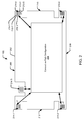
- FIG. 1 diagrammatically illustrates a lighting system 100 that includes a multichannel power supply 101, a plurality of separate substrates 102-1, 102-2... 102-N coupled to each other by associated connectors in a plurality of connectors 104-1, 104-2... 104-N, and a plurality of solid state light sources 106-1, 106-2... 106-N.
- Each of the solid state light sources in the plurality of solid state light sources 106-1, 106-2... 106-N is coupled to an associated one of the substrates in the plurality of substrates 102-1, 102-2... 102-N and to an associated one of the output channels 108 of the multichannel power supply 101.
- the multichannel power supply 101 may be, and in some embodiments is, a known power supply for providing multiple separate output channels 108.
- a variety of multichannel power supply configurations are well-known to those of ordinary skill in the art.
- the multichannel power supply 101 provides K output channels, each of which is established between a Common path 110-1 and a different associated Channel path 112-1, 112-2, 112-3.
- the Kth output channel of the multichannel power supply 101 is established between the Common path 110-1 and the Channel #K path 112-3.
- the common path may be, and in some embodiments is, a common power path and the channel paths may be, and some embodiments are, common ground paths, or vice versa.
- Each output channel of the multichannel power supply 101 is configured to provide an associated drive current, such as but not limited to a constant current drive current, for driving one or more of the solid state light sources in the plurality of solid state light sources 106-1, 106-2...106- N.
- the output channels 108 of the multichannel power supply 101 are directly coupled to associated conductive paths on one of the substrates in the plurality of substrates 102-1, 102-2...102-N.
- the output channels 108 are directly coupled to a substrate #1 102-1.
- the output channels 108 of the multichannel power supply 101 may be, and in some embodiments are, directly coupled to any of the substrates in the plurality of substrates 102-1, 102-2...102-N depending on the desired configuration.
- any known connector configuration may be used to directly couple output channels 108 to a substrate in the plurality of substrates 102-1, 102-2... 102-N.
- the plurality of substrates 102-1, 102-2...102-N may, and in some embodiments do, include a known substrate with a conductive path configuration positioned on and/or through one of the substrates in the plurality of substrates 102-1, 102-2...102-N.
- each substrate in the plurality of substrates 102-1, 102-2...102-N has an identical conductive path configuration.
- a set of conductive paths on one of the substrates in the plurality of substrates 102-1, 102-2...102-N exists identically on all the other substrates in the plurality of substrates 102-1, 102-2...102-N. This allows for use of a single substrate configuration to be used for each of the substrates in the plurality of substrates 102-1, 102-2...102-N and avoids the need to provide different substrate configurations to build the lighting system 100.
- the connectors in the plurality of connectors 104-1, 104-2...104-N may, and in some embodiments do, take any known connector configuration for coupling conductive paths on one substrate in the plurality of substrates 102-1, 102-2...102-N to conductive paths on another of the substrates in the plurality of substrates 102-1, 102-2...102-N.
- the connectors in the plurality of connectors 104-1, 104-2...104-N may be, and in some embodiments are, but are not limited to, known board-to-board connectors for coupling conductive paths on one substrate in the plurality of substrates 102-1, 102-2...102-N to conductive paths on an adjacent substrate in the plurality of substrates 102-1, 102-2...102-N without use of an associated wiring harness.
- the board-to-board connectors may be Series 9159 connectors presently available from AVX Corporation of Greenville, South Carolina, USA, or SEI or SEL Series connectors presently available from Samtec Corporation of New Albany, Indiana, USA.
- Board-to-board connectors provide a cost-effective way to couple conductive paths from one substrate in the plurality of substrates 102-1, 102-2...102-N to an adjacent substrate in the plurality of substrates 102-1, 102-2...102-N without requiring use of a wiring harness. It is to be understood, however, that embodiments may include other connector types and configurations. In some embodiments, for example, it may be useful to configure one or more of the connectors in the plurality of connectors 104-1, 104-2...104-N as a wiring harness for coupling conductive paths of substrates in the plurality of substrates 102-1, 102-2...102-N that are physically separated from each other in a manner that does not allow for efficient use of a board- to-board connector.
- Each of the solid state light sources in the plurality of solid state light sources 106-1, 106-2...106-N may, and in some embodiments do, include groups of solid state light sources configured to emit the same or different colors interconnected in series and/or parallel configurations.
- color generally refers to a property of radiation that is perceivable by an observer (though this usage is not intended to limit the scope of this term). Accordingly, the term “different colors” implies two different spectra with different dominant wavelengths and/or bandwidths. In addition, “color” may be used to refer to white and non-white light.
- Each solid state light source in the plurality of solid state light sources 106-1, 106-2...106-N may include the same, or different, configuration as others of the solid state light sources in the plurality of solid state light sources 106-1, 106-2...106-N.
- each of the solid state light sources in the plurality of solid state light sources 106-1, 106-2...106-N is coupled to an associated one of the substrates in the plurality of substrates 102-1, 102- 2... 102-N and is conductively coupled through the associated substrate in the plurality of substrates 102-1, 102-2...102-N to a different associated channel 108 of the multichannel power supply 101.
- 106-N are coupled to the same conductive paths on different ones of the substrates in the plurality of substrates 102-1, 102-2...102-N while achieving connectivity to different channels 108 of the multichannel power supply 101.
- the substrates in the plurality of substrates 102-1, 102-2...102-N may be, and in some embodiments are, connected to each other using the connectors in the plurality of connectors 104-1, 104-2... 104-N, and one of the substrates in the plurality of substrates 102-1, 102-2...102-N may be directly coupled to the multichannel power supply 101. This allows for efficient assembly of the lighting system 100 wherein multiple solid state light sources in the plurality of solid state light sources 106-1, 106- 2...106-N are coupled to different channels 108 of a multichannel power supply 101.
- each solid state light source in the plurality of solid state light sources 106-1, 106-2...106-N is coupled to an associated one of the substrates in the plurality of substrates 102-1, 102-2...102-N and to a separate channel 108 of the multichannel power supply 101
- any number of solid state light sources may be coupled to a single substrate in the plurality of substrates 102-1, 102-2...102-N.
- the solid state light sources in the plurality of solid state light sources 106-1, 106-2...106-N on the same or different substrates in the plurality of substrates 102-1, 102-2...102-N may be coupled to the same or different channels 108 of the multichannel power supply 101.
- a lighting system may, and in some embodiments does, include any number N of substrates 102-1, 102-2...102-N with any number of light sources 106-1, 106-2...106-N coupled to any number K of output channels 108 of the multichannel power supply 101.
- FIG. 2 there is illustrated a top view of a substrate 102, which includes a substrate 202, a plurality of input/output (I/O) ports J1, J2, J3, J4 and J5, and a conductive path configuration 204 formed on the substrate 202.
- references to conductive paths or a conductive path configuration formed "on" a substrate refers to conductive paths on a surface of the substrate 202 and/or between surfaces of the substrate 202 and/or conductive paths extending completely or partially through the substrate 202.
- the substrate 102 will be referred to as including a top edge 206, a bottom edge 208, a right edge 210 and a left edge 212.
- I/O ports J1 and J2 are provided at the left edge 212, with the I/O port J1 adjacent the top edge 206 and the I/O port J2 adjacent the bottom edge 208.
- I/O ports J3 and J4 are provided at the right edge 210, with the I/O port J3 adjacent the top edge 206 and the I/O port J4 adjacent the bottom edge 208.
- I/O port J5 is provided at the top edge 206 adjacent the left edge 212.
- Each of the I/O ports J1, J2, J3, J4 and J5 includes an associated set of conductive contacts 214-1, 214-2, 214-3, 214-4, 214-5, respectively, positioned at one of the edges 206, 208, 210 or 212 of the substrate 102 to facilitate coupling of each of the contacts in the set of conductive contacts 214-1, 214-2, 214-3, 214- 4, 214-5 to a corresponding pin or conductive contact on a connector in the plurality of connectors 104-1, 104-2...104-N (shown in FIG. 1 ) or to a corresponding output of the multichannel power supply 101.
- Each of the five I/O ports J1, J2, J3, J4 and J5 includes five separate contacts, e.g., contacts 216-1, 216-2, 216-3, 216-4 and 216-5 at the I/O port J3, exposed on the top surface of the substrate 102.
- a substrate 102 according to embodiments disclosed throughout may, and sometimes does, include any number of I/O ports and the I/O ports may be, and sometimes are, positioned at any location on the substrate 102.
- a substrate 102 according to embodiments may, and sometimes does, include any number of conductive contacts sufficient for coupling all the output channels of a multichannel power supply to the substrate 102.
- a multichannel power supply having two channels established between a common path and different associated channel paths may be connected to the substrate using three contacts at each port of the substrate 102.
- the conductive path configuration 204 provides conductive paths between the I/O ports J1, J2, J3, J4 and J5, establishing a pass-through connection between at least two of the I/O ports J1, J2, J3, J4 and J5 and conductive paths establishing a shifting connection between at least two other I/O ports J1, J2, J3, J4 and J5.
- a pass-through connection couples all of the signals coupled to the contacts at one I/O port, e.g. the I/O port J1, to associated contacts of another I/O port, e.g. the I/O port J2.
- the pass-through connection couples all of the signals coupled to the contacts at one I/O port to associated contacts of another I/O port so they are presented to the other I/O port for connection in the same relative order as they were provided to the first I/O port. This allows a common connector type to be used for establishing a pass-through connection from an I/O port on one substrate to an I/O port on another substrate.
- present or “presenting” as used herein when referring to contacts (such as but not limited to the contacts 214-1, 214-2, 214-3, 214-4, 214-5) of an I/O port (such as but not limited to the I/O ports J1, J2, J3, J4 or J5) means that the contacts make electrical connections available on the substrate 102, e.g. at one of the edges 206, 208, 210 or 212 of the substrate 202, so that a connector in the plurality of connectors 104-1, 104-2...104-N (shown in FIG. 1 ), such as but not limited to a board-to-board connector, may be physically and electrically coupled therewith.
- order as used herein when referring to contacts means that the contacts (such as but not limited to the contacts 216- 1, 216-2, 216-3, 216-4 and 216-5), within a set of contacts at an I/O port (such as but not limited to the I/O ports J1, J2, J3, J4 or J5) are physically ordered to present an electrical connection to conductive paths of the conductive path configuration 204 such that the contacts associated with and coupled to different paths are arranged to be physically immediately adjacent each other in an associated order.
- the term "same relative order" as used herein when referring to the contacts (such as but not limited to the contacts 214-1, 214-2, 214-3, 214-4, 214-5) of different I/O ports (such as but not limited to the I/O ports J1, J2, J3, J4 or J5) means that the contacts of a first I/O port present electrical connections to the conductive paths of the conductive path configuration 204 in a first order, and the contacts of a second I/O port present electrical connections to the conductive paths of the conductive path configuration 204 in a second order, such that the each of the contacts of the first I/O port is positioned immediately adjacent one or more other contacts of the first I/O port coupled to associated conductive paths of the conductive path configuration 204, and each contact of the second I/O port is positioned immediately adjacent one or more other contacts of the second I/O port coupled to the same conductive paths.
- a shifting connection couples only some of the signals coupled to the contacts at one I/O port, e.g. the I/O port J2, to associated contacts of another I/O port, e.g. the I/O port J4.
- a shifting connection couples only some of the signals coupled to the contacts at one I/O port, e.g. the I/O port J2, to associated contacts of another I/O port, e.g. the I/O port J4, so that the contacts are presented at the second I/O port in a different relative order compared to how the contacts were presented at the first I/O port.
- Contacts present electrical connections in a "different" relative order as used herein means that the contacts 214-1, 214-2, 214-3, 214-4, 214-5 of a first I/O port in the plurality of I/O ports J1, J2, J3, J4, J5 present electrical connections to the conductive paths of a conductive path configuration 204 in an associated order, and the contacts 214-1, 214-2, 214-3, 214-4, 214- 5 of a second I/O port in the plurality of I/O ports J1, J2, J3, J4, J5 present electrical connections to the conductive paths of the conductive path configuration 204 in a second order, such that the contacts of the first I/O port and second I/O port are immediately adjacent contacts coupled to different electrical paths, or a contact of one I/O port is
- FIG. 3 illustrates one configuration of a conductive path configuration 204a that may be provided on the substrate 102 illustrated in FIG. 2 .
- FIG. 3 shows each of the I/O ports in the plurality of I/O ports J1, J2, J3, J4, J5 with the contacts 214-1, 214-2, 214-3, 214-4, 214-5 associated with each I/O port in the plurality of I/O ports J1, J2, J3, J4, J5, respectively, identified by numerals 1 through 5.
- Pass-through and shifting connections between other I/O ports in the plurality of I/O ports J1, J2, J3, J4, J5 operate in the same manner as described with respect to the pass-through connection between the I/O ports J1 and J3 and the shifting connection between the I/O ports J2 and J4.
- the pass-through connection may be, and in some embodiments is, used to couple conductive paths on one substrate (e.g., the substrate 102-1 shown in FIG. 1 ) to the same conductive paths on a separate substrate (e.g., the substrate 102-2 shown in FIG. 1 ) with identically configured conductive paths.
- the pass-through connection between the I/O ports J1 and J3 is established by a plurality of conductive paths 302-1, 302-2, 302-3, 302-4, 302-5 coupling the contacts 214-1 at the I/O port J1 to corresponding contacts 214-3 at the I/O port J3.
- the contacts 214-1 at the I/O port J1 present electrical connections to the I/O port J3 in the same order as the contacts 214-3 at the I/O port J3 present electrical connections to the I/O port J1.
- a contact 1 of the I/O port J1 is coupled by a conductive path 302-1 to a contact 1 of the I/O port J3
- a contact 2 of the I/O port J1 is coupled by a conductive path 302-2 to a contact 2 of the I/O port J3
- a contact 3 of the I/O port J1 is coupled by a conductive path 302-3 to a contact 3 of the I/O port J3
- a contact 4 of J1 is coupled by a conductive path 302-4 to a contact 4 of the I/O port J3
- a contact 5 of the I/O port J1 is coupled by a conductive path 302-5 to a contact 5 of the I/O port J3.
- the shifting connection may be used to couple conductive paths on one substrate (e.g., the substrate 102-1 shown in FIG. 1 ) to different conductive paths on a separate substrate (e.g., the substrate 102-2 shown in FIG. 1 ) with identically configured conductive paths.
- the shifting connection between the I/O ports J2 and J4 connects only some of the contacts 214-2 at the I/O port J2 to non-corresponding contacts 214-4 of the I/O port J4. In FIG.
- the shifting connection couples a contact 1 of the I/O port J2 to a contact 1 of the I/O port J4 through conductive paths 304-1, 302-1 and 306-1, couples a contact 2 of the I/O port J2 to a contact 3 of the I/O port J4 through conductive paths 304-2, 302-2 and 306-3, couples a contact 3 of the I/O port J2 to a contact 4 of the I/O port J4 through conductive paths 304-3, 302-3, and 306-4, and couples a contact 4 of the I/O port J2 to a contact 5 of the I/O port J4 through conductive paths 304-4, 302-4 and 306-5.
- a contact 5 of the I/O port J2 is not coupled by the conductive path configuration 204a to the I/O port J4, and a contact 2 of the I/O port J4 is not coupled to a contact of any other port (i.e., the I/O ports J1, J2, J3, or J5).
- the contacts 214-2 of the I/O port J2 are presented in a different relative order compared to the contacts 214-4 of the I/O port J4.
- each of contacts 214-5 of the I/O port J5 are coupled to the pass-through conductive paths 302-1, 302-2, 302-3, 302-4 and 302-5 between the I/O ports J1 and J3 by associated conductive paths 308-1, 308-2, 308-3, 308-4, 308-5, respectively.
- the contacts 214-5 of the I/O port J5 present connections to the conductive path configuration 204a that are, for example, useful for connecting the output channels of a multichannel power supply to the conductive path configuration 204a.
- the common connection and channel connections of a multichannel power supply (e.g., the multichannel power supply 101 shown in FIG. 1 ) may each be, and in some embodiments are, coupled to a different associated one of the contacts 214-5 of the I/O port J5.
- two or more substrates in the plurality of substrates 102-1, 102-2 ... 102-N may be and in some embodiments are coupled to each other by coupling an I/O port on one of the substrates in the plurality of substrates 102-1, 102-2 ... 102-N to an I/O port on an adjacent substrate using a connector, e.g. a connector in the plurality of connectors 104-1, 104-2 ... 104-N.
- a connector e.g. a connector in the plurality of connectors 104-1, 104-2 ... 104-N.
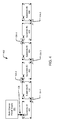
- FIG. 4 diagrammatically illustrates an electrical substrate assembly 402 that includes substrates: a substrate#1 491, a substrate#2 492, a substrate#3 493, a substrate#4 494, a substrate#5 495, and a substrate#6 496, each of which is configured in the same way as the substrate 102 shown in FIG. 2 and includes the same conductive path configuration 204a as illustrated in FIG. 3 .
- the conductive paths of FIG. 3 are not shown in FIG. 4 .
- output channels 108 of a multichannel power supply 101 are coupled to the contacts of an I/O port J5 on the substrate #1 491.
- Contacts of an I/O port J4 on the substrate #1 491 are coupled to contacts of an I/O port J2 on the substrate #2 492 by a first connector 104-1.
- Contacts of an I/O port J3 on the substrate #2 492 are coupled to contacts of an I/O port J1 on the substrate #3 493 by a second connector 104-2.
- Contacts of an I/O port J4 on the substrate #3 493 are coupled to contacts of an I/O port J2 on the substrate #4 494 by a third connector 104-3.
- FIGs. 5A and 5B illustrate the electrical connections established by the configuration of the electrical substrate assembly 402 shown in FIG. 4 , and illustrate a first solid state light source 106-1, a second solid state light source 106-2, a third solid state light source 106-3, a fourth solid state light source 106-4, a fifth solid state light source 106-5, and a sixth solid state light source 106-6 coupled to the substrate#1 491, the substrate#2 492, the substrate#3 493, the substrate#4 494, the substrate#5 495, and the substrate#6 496, respectively, and to the output channels 108 of the multichannel power supply 101.
- the output channels 108 of the multichannel power supply 101 include a common output CMN, a channel 1 output C1, a channel 2 output C2, a channel 3 output C3, and a channel 4 output C4.
- Each of the output channels 108 are coupled to an associated contact of the I/O port J5 on the substrate #1 491.
- the first solid state light source 106-1 includes a plurality of solid state light sources 404 coupled in series between the conductive paths 302-1 and 302-5 of the substrate #1 491, which carry the common output CMN and the channel 4 output C4, respectively.
- the solid state light source 106-4 on the substrate #1 491 is thus coupled to the channel 4 output C4 of the multichannel power supply 101.
- the conductive path configuration 204a establishes a shifting connection between the I/O port J5 and the I/O port J4 of the substrate #1 491, which is coupled to the I/O port J2 of the substrate #2 492 by the first connector 104-1 in FIG. 4 .
- the common output CMN, the channel 1 output C1, the channel 2 output C2, and the channel 3 output C3 of the multichannel power supply 101 are coupled to the I/O port J2 of the substrate#2 492.
- the second contact on the I/O port J4 of the substrate #1 491 has no connection NC and is coupled to the second contact of the I/O port J2 on the substrate #2 492.
- the conductive path configuration 204a establishes a pass-through connection between the I/O ports J2 and J3 on the substrate #2 492, coupling the contacts of the I/O port J2 to the conductive paths established between the I/O ports J1 and J3 on the substrate #2 492.
- the second solid state light source 106-2 includes a plurality of solid state light sources 404 coupled in series between the conductive paths 302-1 and 302-5 of the substrate #2 492, which correspond (i.e., are the same paths) to which the first solid state light source 106-1 is coupled on the substrate #1 491.
- the conductive paths 302-1 and 305-1 carry the common output CMN and the channel 3 output C3 of the multichannel power supply 101.
- the second solid state light source 106-2 is thus coupled to the channel 3 output C3 of the multichannel power supply 101.
- the substrate #1 491 and the substrate #2 492 have the same conductive path configurations 204a
- the first solid state light source 106-1 and the second solid state light source 106-2 coupled to the same conductive paths 302-1 and 302-5 on the substrate #1 491 and the substrate#2 492, respectively are coupled to different output channels, i.e. the output channel 4 C4 and the output channel 3 C3, respectively, of the multichannel power supply 101, due to the shifting connection between the I/O ports J5 and J4 of the substrate#1 491, which is coupled to the I/O port J2 of the substrate #2 492.
- the pass-through connection between the I/O ports J2 and J3 of the substrate #2 492 is coupled to the I/O port J1 of the substrate #3 493 by the second connector 104-2 in FIG. 4 .
- the common output CMN, the channel 1 output C1, the channel 2 output C2, and the channel 3 output C3 of the multichannel power supply 101 from the I/O port J3 on the substrate #2 492 are coupled to corresponding contacts of the I/O port J1 on the substrate #3 493.
- the third solid state light 106-3 source includes a plurality of solid state light sources 404 coupled in series between the conductive paths 302-1 and 302-5, which correspond to the conductive paths to which the first solid state light source 106-1 and the second solid state light source 106-2 are coupled on the substrate # 1 491 and the substrate #2 492, respectively. Due to the pass-through connection paths 302-1 and 302-5 on the substrate #3 493 carrying the common output CMN and the channel 3 output C3 of the multichannel power supply 101, the third solid state light source 106-3 is thus coupled to the channel 3 output C3 of the multichannel power supply 101.
- Connections to the substrate #4 494, the substrate #5 495, and the substrate #6 similarly use either a shifting connection and a connector (e.g., the connector 104-3, the connector 104-5) between an I/O port J4 and an I/O port J2 of adjacent substrates, or a pass-through connection and a connector (e.g., the connector 104-4) between an I/O port J3 and an I/O port J1 of adjacent substrates.
- the connector 104-3 between the substrate #3 493 and the substrate #4 494 couples a shifting connection on the substrate #3 493 to the substrate #4 494.
- the fourth solid state light source 106-4 includes a plurality of solid state light sources 404 coupled in series between the conductive paths 302-1 and 302-5 on the substrate #4 494. Due to the shifting connection, however, on the substrate #4 494, the conductive paths 302-1 and 302-5 carry the common output CMN and the channel 2 output C2 of the multichannel power supply 101, and thus the fourth solid state light source 106-4 is coupled to the channel 2 output C2 of the multichannel power supply 101.
- the connector 104-4 between the substrate #4 494 and the substrate #5 495 couples a pass-through connection on the substrate #4 494 to the substrate #5 495.
- the fifth solid state light source 106-5 includes a plurality of solid state light sources 404 coupled in series between the conductive paths 302-1 and 305-1 on the substrate #5 495. Due to the pass-through connection, on the substrate #5 495, the conductive paths 302-1 and 305-1 carry the common output CMN and the channel 2 output C2 of the multichannel power supply 101. The fifth solid state light source 106-5 is thus coupled to the channel 2 output C2 of the multichannel power supply 101.
- the connector 104-5 between the substrate #5 495 and the substrate #6 496 couples a shifting connection on the substrate #5 495 to the substrate #6 496.
- the sixth solid state light source 106-6 includes a plurality of solid state light sources 404 coupled in series between the conductive paths 302-1 and 305-1 on the substrate #6 496. Due to the shifting connection, however, on the substrate #6 496, the conductive paths 302-1 and 305-1 carry the common output CMN and the channel 1 output C1 of the multichannel power supply 101, and thus the sixth solid state light source 106-6 is coupled to the channel 1 output C1 of the multichannel power supply 101.
- a substrate is coupled to a multichannel power supply and to other substrates, by pass-through and/or shifting connections.
- Solid state light sources coupled to the same conductive paths on the respective substrates are thereby coupled to selected channels of the multichannel power supply.
- a single substrate configuration is thus utilized to achieve selective coupling of solid state light sources to different channels of a multichannel power supply.
- the solid state light sources are coupled to the same conductive paths on respective substrates to allow ease of assembly, and the substrates are coupled to each other through pass-through connections or shifting connections to selectively couple the solid state light sources to desired channels of the multichannel power supply.
- a single wiring harness may be, and in some embodiments is, used to couple a multichannel power supply to a port on one of the substrates.
- Board-to-board connectors may be, and in some embodiments are, used to couple substrates to each other. This avoids the expense associated with using multiple wiring harnesses to couple a multichannel power supply to multiple substrates including one or more solid state light sources.
- a multichannel power supply may be, and in some embodiments is, coupled to a substrate as described throughout using any of a variety of connector configurations.
- a connector configuration 602 for coupling a multichannel power supply to a substrate is illustrated in FIG. 6 , along with a portion of the substrate 102 shown in FIG. 2 , including the I/O ports J2 and J5.
- the connector configuration 602 includes a wiring harness 604, an interface substrate 606, and a known board-to-board connector 104-1a.
- the wiring harness 604 includes a plurality of conductive wires 608 coupled thereto and to associated contacts on the interface substrate 606.
- the plurality of conductive wires 608 may, and in some embodiments do, originate from the multichannel power supply (not shown in FIG.
- the interface substrate 606 may, and in some embodiments does, include conductive paths thereon for coupling contacts of the wire harness 604 to contacts on the board-to-board connector 104-1a.
- the board-to-board connector 104-1a may be, and in some embodiments is, coupled to the I/O port J5 to couple the contacts 214-5 (shown in phantom) of the I/O port J5 to associated ones of the conductive wires 608 of the multichannel power supply through the interface substrate 606.
- FIGs. 7 and 8 illustrate a first substrate 791 coupled to a second substrate 792 using a separate contact bridge 702.
- the contact bridge 702 includes a substrate 802, a first fastener 804 and a second fastener 806 extending through the substrate 802, and a first contact configuration 808 and a second contact configuration 810 disposed on the substrate 802.
- the first contact configuration 808 and the contact configuration 810 extend outwardly from the substrate 802 and may (and in some embodiments do) include contacts corresponding to the contacts 214 (shown in phantom) on ports of the first substrate 791 and the second substrate 792.
- FIG. 9 illustrates a contact bridge configuration 702a that may be, and in some embodiments is, used to couple a multichannel power supply to a port on a substrate, e.g. the first substrate 791 of FIG. 7 .
- the contact bridge configuration 702a includes a substrate 902, a connector 904 coupled to the substrate 902, a fastener 906 extending through the substrate 902, and a contact configuration 908 disposed on the substrate 902.
- the connector 904 may, and in some embodiments does, include a plurality of conductive wires 910 coupled to respective channels of the multichannel power supply and may couple the leads to associated conductive paths on the substrate 902 that are coupled to associated contacts of the contact configuration 908.
- the contact configuration 908 may extend outwardly from the substrate 902 and may include contacts corresponding to the contacts 214 (shown in FIG. 7 ) on the ports on the first substrate 791 shown in FIG. 7 .
- the fastener 906, shown as but not limited to a screw, may be passed through a corresponding opening, e.g. the opening 704 shown in FIG. 7 , in the substrate 902 and the contact configuration 908 may contact the contacts 214 of a port, thereby coupling the outputs of the multichannel power supply with the contacts 214 of the port on board.
- FIG. 10 is a flowchart illustrating a method 1000 of coupling output channels of a multichannel power supply to solid state light sources.
- the illustrated flowchart may be shown and described as including a particular sequence of steps. It is to be understood, however, that the sequence of steps merely provides an example of how the general functionality described herein may be implemented. The steps do not have to be executed in the order presented unless otherwise indicated.
- the method 1000 begins by providing a plurality of substrates, each of the plurality of substrates having a plurality of ports and the same conductive path configuration thereon, step 1001.
- Output channels of a multichannel power supply are coupled to a first substrate in the plurality of substrates, step 1002.
- a first port in the plurality of ports on the first substrate in the plurality of substrates is coupled to a first port in the plurality of ports on a second substrate in the plurality of substrates, step 1003.
- a first solid state light source is coupled to first and second conductive paths of the conductive path configuration on the first substrate in the plurality of substrates, whereby the first solid state light source is coupled to a first output channel of the multichannel power supply, step 1004.
- a second solid state light source is coupled to to first and second conductive paths of the conductive path configuration on the second substrate in the plurality of substrates corresponding to the first and second conductive paths of the conductive path configuration on the first substrate in the plurality of substrates, whereby the second solid state light source is coupled to a second output channel of the multichannel power supply, the second output channel being different from the first output channel, step 1005.
- the plurality of ports on the first substrate in the plurality of substrates includes a first port having a first set of electrical contacts, a second port having a second set of electrical contacts, a third port having a third set of electrical contacts, and a fourth port having a fourth set of electrical contacts.
- the conductive path configuration establishes a pass-through connection from the first port to the third port and a shifting connection from the second port to the fourth port.
- the pass-through connection couples each of the first set of electrical contacts to associated ones of the third set of electrical contacts.
- the shifting connection couples a portion of the second set of electrical contacts to associated ones of the fourth set of electrical contacts with at least one contact of the second set of electrical contacts not being connected to any contact of the fourth set of electrical contacts.
- the conductive path configuration establishes a pass-through connection from the first port to the third port and a shifting connection from the second port to the fourth port, wherein the pass-through connection couples each of the first set of electrical contacts to associated ones of the third set of electrical contacts, and wherein the shifting connection couples a portion of the second set of electrical contacts to associated ones of the fourth set of electrical contacts with at least one contact of the second set of electrical contacts not being connected to any contact of the fourth set of electrical contacts.
- first set of electrical contacts presents an associated electrical connection to the conductive path configuration in a first order relative to each other and the third set of electrical contacts presents an associated electrical connection to the conductive path configuration in a third order relative to each other, the first order being the same relative order as the third order.
- the conductive path configuration when coupling a first port step 1003, establishes a pass-through connection from the first port to the third port and a shifting connection from the second port to the fourth port, wherein the pass-through connection couples each of the first set of electrical contacts to associated ones of the third set of electrical contacts, and wherein the shifting connection couples a portion of the second set of electrical contacts to associated ones of the fourth set of electrical contacts with at least one contact of the second set of electrical contacts not being connected to any contact of the fourth set of electrical contacts.
- the second set of electrical contacts presents an associated electrical connection to the conductive path configuration in a second order relative to each other and the fourth set of electrical contacts presents an associated electrical connection to the conductive path configuration in a fourth order relative to each other, the fourth order being a different order from the second order.
- coupling a first port step 1003 includes a fifth port having a fifth set of electrical contacts
- the conductive path configuration establishes a pass-through connection from the first port to the third port and a shifting connection from the second port to the fourth port, wherein the pass-through connection couples each of the first set of electrical contacts to associated ones of the third set of electrical contacts, and wherein the shifting connection couples a portion of the second set of electrical contacts to associated ones of the fourth set of electrical contacts with at least one contact of the second set of electrical contacts not being connected to any contact of the fourth set of electrical contacts, each contact of the fifth set of electrical contacts is coupled to the pass-through connection.
Landscapes
- Engineering & Computer Science (AREA)
- General Engineering & Computer Science (AREA)
- Arrangement Of Elements, Cooling, Sealing, Or The Like Of Lighting Devices (AREA)
- Coupling Device And Connection With Printed Circuit (AREA)
Applications Claiming Priority (1)
| Application Number | Priority Date | Filing Date | Title |
|---|---|---|---|
| US201261694050P | 2012-08-28 | 2012-08-28 |
Publications (2)
| Publication Number | Publication Date |
|---|---|
| EP2704530A2 true EP2704530A2 (de) | 2014-03-05 |
| EP2704530A3 EP2704530A3 (de) | 2015-07-08 |
Family
ID=49118293
Family Applications (1)
| Application Number | Title | Priority Date | Filing Date |
|---|---|---|---|
| EP13181698.5A Withdrawn EP2704530A3 (de) | 2012-08-28 | 2013-08-26 | Modulares, mehrkanaliges Verbindersystem und Verfahren |
Country Status (3)
| Country | Link |
|---|---|
| US (1) | US9022602B2 (de) |
| EP (1) | EP2704530A3 (de) |
| CN (2) | CN103672667B (de) |
Families Citing this family (1)
| Publication number | Priority date | Publication date | Assignee | Title |
|---|---|---|---|---|
| WO2021007771A1 (en) * | 2019-07-16 | 2021-01-21 | 3M Innovative Properties Company | Optical transceiver module |
Family Cites Families (17)
| Publication number | Priority date | Publication date | Assignee | Title |
|---|---|---|---|---|
| US6851831B2 (en) * | 2002-04-16 | 2005-02-08 | Gelcore Llc | Close packing LED assembly with versatile interconnect architecture |
| US7108392B2 (en) * | 2004-05-04 | 2006-09-19 | Eastman Kodak Company | Tiled flat panel lighting system |
| JP4583956B2 (ja) * | 2005-02-10 | 2010-11-17 | Necライティング株式会社 | 面状光源装置の製造方法 |
| WO2009040705A2 (en) * | 2007-09-28 | 2009-04-02 | Koninklijke Philips Electronics N.V. | Method and apparatus for light intensity control with drive current modulation |
| US8634941B2 (en) * | 2008-04-01 | 2014-01-21 | Infineon Technologies Austria Ag | System and method for multi-channel control system |
| SE0950298A1 (sv) * | 2009-05-04 | 2010-11-05 | Vadsbo Innovation Ab | Arrangemang av elektrisk krets |
| US8454195B2 (en) * | 2009-09-18 | 2013-06-04 | Luxingtek, Ltd. | Lighting device, lighting panel and circuit board thereof |
| CN101674693B (zh) * | 2009-10-01 | 2012-07-18 | 英飞特电子(杭州)有限公司 | 一种适用于led驱动器的多路恒流控制电路 |
| US8294375B2 (en) * | 2009-10-08 | 2012-10-23 | Intersil Americas Inc | Adaptive PWM controller for multi-phase LED driver |
| CN201766747U (zh) * | 2009-11-21 | 2011-03-16 | 英飞特电子(杭州)有限公司 | 多路恒流驱动电路 |
| DE102009054511A1 (de) * | 2009-12-10 | 2011-06-16 | Osram Gesellschaft mit beschränkter Haftung | Verfahren zum Kontaktieren einer Leuchtvorrichtung, Werkzeug zum Durchführen des Verfahrens und Anschlusselement zum Aufsatz auf eine Leuchtvorrichtung |
| WO2011089536A1 (en) * | 2010-01-22 | 2011-07-28 | Koninklijke Philips Electronics N.V. | Lighting device comprising a plurality of light emitting tiles |
| KR20120084555A (ko) * | 2011-01-20 | 2012-07-30 | 삼성전자주식회사 | 다채널 펄스 폭 변조(pwm) 신호 생성 장치 및 방법, 이를 구비하는 led 시스템 |
| KR20120095656A (ko) * | 2011-02-21 | 2012-08-29 | 삼성전기주식회사 | Led 구동장치 |
| US9538597B2 (en) * | 2011-08-25 | 2017-01-03 | Osram Sylvania Inc. | Multichannel power supply |
| CN102635835B (zh) * | 2012-03-30 | 2014-04-16 | 北京朗波尔光电股份有限公司 | 一种可快捷拆装的连接结构 |
| US20140268781A1 (en) * | 2013-03-15 | 2014-09-18 | Spire Manufacturing, Inc. | Modular LED (Light Emitting Diode) Lighting System and Method of Assembling Same |
-
2013
- 2013-06-24 US US13/924,961 patent/US9022602B2/en not_active Expired - Fee Related
- 2013-08-26 EP EP13181698.5A patent/EP2704530A3/de not_active Withdrawn
- 2013-08-27 CN CN201310377747.4A patent/CN103672667B/zh not_active Expired - Fee Related
- 2013-08-27 CN CN201710053752.8A patent/CN107062160A/zh active Pending
Non-Patent Citations (1)
| Title |
|---|
| None |
Also Published As
| Publication number | Publication date |
|---|---|
| US20140063804A1 (en) | 2014-03-06 |
| EP2704530A3 (de) | 2015-07-08 |
| US9022602B2 (en) | 2015-05-05 |
| CN107062160A (zh) | 2017-08-18 |
| CN103672667A (zh) | 2014-03-26 |
| CN103672667B (zh) | 2017-07-18 |
Similar Documents
| Publication | Publication Date | Title |
|---|---|---|
| US9377173B2 (en) | LED luminaire assembly | |
| US7470055B2 (en) | Mounting structure for LED lighting systems | |
| US8197079B2 (en) | Flexible LED lighting systems, fixtures and method of installation | |
| US6851831B2 (en) | Close packing LED assembly with versatile interconnect architecture | |
| US10941930B2 (en) | Radially symmetric electrical connector | |
| US8736527B2 (en) | Flexible LED pixel string with two shielding ground lines | |
| US20150285474A1 (en) | Printed circuit board for populating with illumination bodies, comprising a variable working window | |
| EP3165055B1 (de) | Teilbare lichtketten und verfahren zum teilen von lichtketten | |
| WO2010108751A1 (de) | Leuchtmodul, nullkraftverbindungselement und stromversorgung für ein leuchtband | |
| US10512128B2 (en) | Modular light-emitting diode fixtures | |
| US9797582B2 (en) | Printed circuit board for a lamp | |
| EP2688367A1 (de) | LED-Modul, Rohrleuchte und Leuchte | |
| US10854800B2 (en) | Light emitting device, light emitting module, and illuminating apparatus | |
| EP2704530A2 (de) | Modulares, mehrkanaliges Verbindersystem und Verfahren | |
| KR102428681B1 (ko) | 조명 장치 | |
| US8950897B2 (en) | Light-emitting device and lighting apparatus | |
| US20130170213A1 (en) | Light-emitting diode module | |
| US20200381602A1 (en) | Light-emitting module and surface-emitting light source | |
| EP2587137B1 (de) | Beleuchtungsvorrichtung und Beleuchtungsbefestigung | |
| KR20200055914A (ko) | Led 모듈의 병렬연결이 가능한 led 조명장치 | |
| US10477685B2 (en) | Light-emitting diode circuit board | |
| KR102835616B1 (ko) | Led 모듈 구조체의 전원 연결 커넥터 | |
| EP3450833B1 (de) | Elektronische vorrichtung und beleuchtungsmodul | |
| EP2725284A1 (de) | Miteinander anschließbare LED-Module und Verfahren zum miteinander Anschließen von LED-Modulen | |
| US9860951B1 (en) | Systems and methods for balancing current among light-emitting diode boards |
Legal Events
| Date | Code | Title | Description |
|---|---|---|---|
| AK | Designated contracting states |
Kind code of ref document: A2 Designated state(s): AL AT BE BG CH CY CZ DE DK EE ES FI FR GB GR HR HU IE IS IT LI LT LU LV MC MK MT NL NO PL PT RO RS SE SI SK SM TR |
|
| AX | Request for extension of the european patent |
Extension state: BA ME |
|
| PUAI | Public reference made under article 153(3) epc to a published international application that has entered the european phase |
Free format text: ORIGINAL CODE: 0009012 |
|
| PUAL | Search report despatched |
Free format text: ORIGINAL CODE: 0009013 |
|
| AK | Designated contracting states |
Kind code of ref document: A3 Designated state(s): AL AT BE BG CH CY CZ DE DK EE ES FI FR GB GR HR HU IE IS IT LI LT LU LV MC MK MT NL NO PL PT RO RS SE SI SK SM TR |
|
| AX | Request for extension of the european patent |
Extension state: BA ME |
|
| RIC1 | Information provided on ipc code assigned before grant |
Ipc: H05B 33/08 20060101AFI20150602BHEP |
|
| 17P | Request for examination filed |
Effective date: 20150908 |
|
| RBV | Designated contracting states (corrected) |
Designated state(s): AL AT BE BG CH CY CZ DE DK EE ES FI FR GB GR HR HU IE IS IT LI LT LU LV MC MK MT NL NO PL PT RO RS SE SI SK SM TR |
|
| 17Q | First examination report despatched |
Effective date: 20180223 |
|
| STAA | Information on the status of an ep patent application or granted ep patent |
Free format text: STATUS: THE APPLICATION IS DEEMED TO BE WITHDRAWN |
|
| 18D | Application deemed to be withdrawn |
Effective date: 20180706 |