EP2704415A1 - Dispositif d'imagerie à grand angle de vue - Google Patents
Dispositif d'imagerie à grand angle de vue Download PDFInfo
- Publication number
- EP2704415A1 EP2704415A1 EP13181910.4A EP13181910A EP2704415A1 EP 2704415 A1 EP2704415 A1 EP 2704415A1 EP 13181910 A EP13181910 A EP 13181910A EP 2704415 A1 EP2704415 A1 EP 2704415A1
- Authority
- EP
- European Patent Office
- Prior art keywords
- ball
- lens
- matrix
- imaging device
- detect
- Prior art date
- Legal status (The legal status is an assumption and is not a legal conclusion. Google has not performed a legal analysis and makes no representation as to the accuracy of the status listed.)
- Withdrawn
Links
- 238000003384 imaging method Methods 0.000 title claims abstract description 16
- 238000001514 detection method Methods 0.000 claims abstract description 26
- 239000011159 matrix material Substances 0.000 claims abstract description 18
- 238000005096 rolling process Methods 0.000 claims description 2
- 230000003287 optical effect Effects 0.000 description 10
- 230000005855 radiation Effects 0.000 description 4
- 238000012634 optical imaging Methods 0.000 description 3
- 238000010438 heat treatment Methods 0.000 description 2
- 238000004378 air conditioning Methods 0.000 description 1
- 230000004075 alteration Effects 0.000 description 1
- 238000001914 filtration Methods 0.000 description 1
- 239000003292 glue Substances 0.000 description 1
- 239000000463 material Substances 0.000 description 1
- 230000004048 modification Effects 0.000 description 1
- 238000012986 modification Methods 0.000 description 1
- 238000000465 moulding Methods 0.000 description 1
- 230000003071 parasitic effect Effects 0.000 description 1
Images


Classifications
-
- H—ELECTRICITY
- H04—ELECTRIC COMMUNICATION TECHNIQUE
- H04N—PICTORIAL COMMUNICATION, e.g. TELEVISION
- H04N5/00—Details of television systems
- H04N5/222—Studio circuitry; Studio devices; Studio equipment
-
- G—PHYSICS
- G02—OPTICS
- G02B—OPTICAL ELEMENTS, SYSTEMS OR APPARATUS
- G02B13/00—Optical objectives specially designed for the purposes specified below
- G02B13/06—Panoramic objectives; So-called "sky lenses" including panoramic objectives having reflecting surfaces
-
- F—MECHANICAL ENGINEERING; LIGHTING; HEATING; WEAPONS; BLASTING
- F16—ENGINEERING ELEMENTS AND UNITS; GENERAL MEASURES FOR PRODUCING AND MAINTAINING EFFECTIVE FUNCTIONING OF MACHINES OR INSTALLATIONS; THERMAL INSULATION IN GENERAL
- F16M—FRAMES, CASINGS OR BEDS OF ENGINES, MACHINES OR APPARATUS, NOT SPECIFIC TO ENGINES, MACHINES OR APPARATUS PROVIDED FOR ELSEWHERE; STANDS; SUPPORTS
- F16M11/00—Stands or trestles as supports for apparatus or articles placed thereon ; Stands for scientific apparatus such as gravitational force meters
- F16M11/02—Heads
- F16M11/04—Means for attachment of apparatus; Means allowing adjustment of the apparatus relatively to the stand
- F16M11/043—Allowing translations
-
- F—MECHANICAL ENGINEERING; LIGHTING; HEATING; WEAPONS; BLASTING
- F16—ENGINEERING ELEMENTS AND UNITS; GENERAL MEASURES FOR PRODUCING AND MAINTAINING EFFECTIVE FUNCTIONING OF MACHINES OR INSTALLATIONS; THERMAL INSULATION IN GENERAL
- F16M—FRAMES, CASINGS OR BEDS OF ENGINES, MACHINES OR APPARATUS, NOT SPECIFIC TO ENGINES, MACHINES OR APPARATUS PROVIDED FOR ELSEWHERE; STANDS; SUPPORTS
- F16M11/00—Stands or trestles as supports for apparatus or articles placed thereon ; Stands for scientific apparatus such as gravitational force meters
- F16M11/02—Heads
- F16M11/04—Means for attachment of apparatus; Means allowing adjustment of the apparatus relatively to the stand
- F16M11/06—Means for attachment of apparatus; Means allowing adjustment of the apparatus relatively to the stand allowing pivoting
- F16M11/12—Means for attachment of apparatus; Means allowing adjustment of the apparatus relatively to the stand allowing pivoting in more than one direction
- F16M11/14—Means for attachment of apparatus; Means allowing adjustment of the apparatus relatively to the stand allowing pivoting in more than one direction with ball-joint
-
- F—MECHANICAL ENGINEERING; LIGHTING; HEATING; WEAPONS; BLASTING
- F16—ENGINEERING ELEMENTS AND UNITS; GENERAL MEASURES FOR PRODUCING AND MAINTAINING EFFECTIVE FUNCTIONING OF MACHINES OR INSTALLATIONS; THERMAL INSULATION IN GENERAL
- F16M—FRAMES, CASINGS OR BEDS OF ENGINES, MACHINES OR APPARATUS, NOT SPECIFIC TO ENGINES, MACHINES OR APPARATUS PROVIDED FOR ELSEWHERE; STANDS; SUPPORTS
- F16M13/00—Other supports for positioning apparatus or articles; Means for steadying hand-held apparatus or articles
- F16M13/02—Other supports for positioning apparatus or articles; Means for steadying hand-held apparatus or articles for supporting on, or attaching to, an object, e.g. tree, gate, window-frame, cycle
-
- F—MECHANICAL ENGINEERING; LIGHTING; HEATING; WEAPONS; BLASTING
- F16—ENGINEERING ELEMENTS AND UNITS; GENERAL MEASURES FOR PRODUCING AND MAINTAINING EFFECTIVE FUNCTIONING OF MACHINES OR INSTALLATIONS; THERMAL INSULATION IN GENERAL
- F16M—FRAMES, CASINGS OR BEDS OF ENGINES, MACHINES OR APPARATUS, NOT SPECIFIC TO ENGINES, MACHINES OR APPARATUS PROVIDED FOR ELSEWHERE; STANDS; SUPPORTS
- F16M13/00—Other supports for positioning apparatus or articles; Means for steadying hand-held apparatus or articles
- F16M13/02—Other supports for positioning apparatus or articles; Means for steadying hand-held apparatus or articles for supporting on, or attaching to, an object, e.g. tree, gate, window-frame, cycle
- F16M13/027—Ceiling supports
-
- G—PHYSICS
- G03—PHOTOGRAPHY; CINEMATOGRAPHY; ANALOGOUS TECHNIQUES USING WAVES OTHER THAN OPTICAL WAVES; ELECTROGRAPHY; HOLOGRAPHY
- G03B—APPARATUS OR ARRANGEMENTS FOR TAKING PHOTOGRAPHS OR FOR PROJECTING OR VIEWING THEM; APPARATUS OR ARRANGEMENTS EMPLOYING ANALOGOUS TECHNIQUES USING WAVES OTHER THAN OPTICAL WAVES; ACCESSORIES THEREFOR
- G03B37/00—Panoramic or wide-screen photography; Photographing extended surfaces, e.g. for surveying; Photographing internal surfaces, e.g. of pipe
- G03B37/06—Panoramic or wide-screen photography; Photographing extended surfaces, e.g. for surveying; Photographing internal surfaces, e.g. of pipe involving anamorphosis
-
- H—ELECTRICITY
- H04—ELECTRIC COMMUNICATION TECHNIQUE
- H04N—PICTORIAL COMMUNICATION, e.g. TELEVISION
- H04N23/00—Cameras or camera modules comprising electronic image sensors; Control thereof
- H04N23/20—Cameras or camera modules comprising electronic image sensors; Control thereof for generating image signals from infrared radiation only
-
- H—ELECTRICITY
- H04—ELECTRIC COMMUNICATION TECHNIQUE
- H04N—PICTORIAL COMMUNICATION, e.g. TELEVISION
- H04N23/00—Cameras or camera modules comprising electronic image sensors; Control thereof
- H04N23/50—Constructional details
- H04N23/55—Optical parts specially adapted for electronic image sensors; Mounting thereof
-
- H—ELECTRICITY
- H04—ELECTRIC COMMUNICATION TECHNIQUE
- H04N—PICTORIAL COMMUNICATION, e.g. TELEVISION
- H04N23/00—Cameras or camera modules comprising electronic image sensors; Control thereof
- H04N23/60—Control of cameras or camera modules
- H04N23/69—Control of means for changing angle of the field of view, e.g. optical zoom objectives or electronic zooming
-
- H—ELECTRICITY
- H04—ELECTRIC COMMUNICATION TECHNIQUE
- H04N—PICTORIAL COMMUNICATION, e.g. TELEVISION
- H04N23/00—Cameras or camera modules comprising electronic image sensors; Control thereof
- H04N23/60—Control of cameras or camera modules
- H04N23/698—Control of cameras or camera modules for achieving an enlarged field of view, e.g. panoramic image capture
-
- F—MECHANICAL ENGINEERING; LIGHTING; HEATING; WEAPONS; BLASTING
- F16—ENGINEERING ELEMENTS AND UNITS; GENERAL MEASURES FOR PRODUCING AND MAINTAINING EFFECTIVE FUNCTIONING OF MACHINES OR INSTALLATIONS; THERMAL INSULATION IN GENERAL
- F16M—FRAMES, CASINGS OR BEDS OF ENGINES, MACHINES OR APPARATUS, NOT SPECIFIC TO ENGINES, MACHINES OR APPARATUS PROVIDED FOR ELSEWHERE; STANDS; SUPPORTS
- F16M2200/00—Details of stands or supports
- F16M2200/02—Locking means
- F16M2200/021—Locking means for rotational movement
- F16M2200/022—Locking means for rotational movement by friction
Definitions
- the present invention relates to a wide-angle imaging device and more particularly to such an imaging device for detecting the presence of individuals in an observed scene.
- an imaging device with a wide angle of view, for example on the ceiling of a room, or in a corner of any enclosure, to generally scan the scene to be monitored and allow to make the image of this speaker on a sensor.
- an imaging device with a wide angle of view, for example on the ceiling of a room, or in a corner of any enclosure, to generally scan the scene to be monitored and allow to make the image of this speaker on a sensor.
- it will be preferable to record on the sensor a thermal image of the scene by using a system operating in the infrared, for example at infrared wavelengths close to 10. .mu.m.
- radii in the visible range may be used.
- An embodiment of the present invention provides an imaging device comprising an element with at least one sphere-sphere reflective wall, a converging lens, and an image-detection array, in which the lens and the matrix are fixedly mounted. relative to each other on a mount, this mount being articulated with respect to the element.
- the frame is mounted on the element in ball joint connection, in sliding connection or in pivot-sliding connection.
- the articulation between the frame and the element is made at the level of the wall surface.
- the matrix and the lens are arranged with respect to the element so that a beam that would be transmitted by the lens of the matrix to the element reaches only part of the wall and is reflected to an area with an angular extent greater than 90 °.
- the device further comprises a diaphragm placed between the element and the convergent lens.
- the element is a ball.
- the element is a ball rolling ball.
- the ball has a radius of between 7 and 15 mm.
- the lens has a diameter of the order of 5 to 20 mm and a focal length of the same order of magnitude.
- the image detection matrix is adapted to detect infrared rays, the device being adapted to detect the presence of persons placed several meters away from the element.
- the image detection matrix is adapted to detect rays in the visible range, the device being adapted to detect movements of objects placed several meters away from the element.
- the frame comprises a plurality of arms enclosing the element between them and mounted in a ball joint connection with the element.
- the lens is a Fresnel lens.
- An embodiment further provides a use of the above imaging device for the detection of persons and / or motion detection in a scene.
- the figure 1 represents the optical scheme of a wide-angle imaging device.
- This device comprises a sensor 1 consisting of an image detection matrix device comprising a matrix of light-sensitive pixels, possibly of bolometric type, that is to say sensitive to the heating caused by the light and more particularly by infrared radiation. In the case of motion detection, the detection matrix device 1 may be sensitive to radiation in the visible range.
- the imaging device also comprises a convergent lens 2, a diaphragm 3 and a reflective ball 5.
- the lens 2 constitutes a device with a high numerical aperture, for example of the order of unity, in the case where its focal length is equal to its diameter.
- the diaphragm 3 is positioned between the lens 2 and the ball 5 so as to fix the limits of the light beams (for filtering parasitic rays and limiting the aberrations).
- the sensor 1 is disposed slightly behind the focus of the lens 2, the ball acting as a divergent lens (high divergent power). In the example illustrated, the optical axis of the lens intersects the ball towards the bottom of it and is spaced a distance d from the center of the ball.
- a and A ' denote two opposite ends of the sensor, the most divergent rays are the rays which go from the point A to the opposite end of the lens 2 and the point A' at the opposite end of this lens. These rays delimit a beam which strikes between points B 'and B reflective ball 5 from which they are reflected in directions corresponding to radii designated by references C' and C to a scene to be observed.
- the opening angle ⁇ of the beam delimited by the radii C and C ' may be large, for example greater than 90 °, if the focal length of the lens 2, the position of the sensor 1 and the distance between the lens and the sensor are suitably chosen.
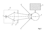
- the figure 2 illustrates an alternative embodiment of the wide angle optical imaging device of the figure 1 .
- a sensor 1 consisting of an image detection matrix device comprising a matrix of light-sensitive pixels.
- the detection matrix device 1 may be designed to be sensitive to radiation in the visible range or in the infrared, depending on the desired application.
- the imaging device also comprises a converging lens 2, a diaphragm 3 and a reflective ball 5.
- the diaphragm 3 is positioned between the lens 2 and the ball 5 so as to fix the limits of the light beams.
- the sensor 1 is arranged slightly behind the focus of the lens 2, the ball behaving as a divergent lens. In the illustrated example, the optical axis of the lens 2 intersects the ball at its center.
- a and A ' denote two opposite ends of the sensor, the most divergent rays are the rays which go from the point A to the opposite end of the lens 2 and the point A' at the opposite end of this lens. These rays delimit a beam which strikes between points B 'and B the reflective ball 5 from which they are reflected in directions corresponding to radii designated by references C 'and C to a scene to be observed.
- the opening angle ⁇ of the beam delimited by the radii C and C ' may be large, for example greater than 90 °, if the focal length of the lens 2, the position of the sensor 1 and the distance between the lens and the sensor are suitably chosen.
- the observed scene is behind the detection system 10.
- the ball 5 is for example integral with a support 11 intended to be fixed to the ceiling or on a wall of an enclosure to monitor.
- the assembly of the lens and the sensor 1 is connected to a frame 13 so that the distance between the lens and the sensor is kept fixed.
- the mount 13 is preferably articulated on the ball 5 to allow to vary the direction and possibly the opening of the observation beam C'-C.
- ball 5 a ball of the type used in ball bearings.
- the standards imposed for the realization of the ball-bearing balls make that they have a shape substantially spherical with an extremely low roughness and in particular much lower than the optical wavelength considered, more particularly in the case where the optical wave to be detected has a wavelength of the order of 10 microns.
- the lens 2 may be a simple lens, for example of the Fresnel lens type, made by molding a plastic material.
- the matrix sensor 1 will not be described in detail since many embodiments of such sensors are well known in the art.
- the wide angle imaging device described above has some optical distortion and in particular obstruction vignetting phenomena (due to the possible presence of the sensor in the field).
- the sensor will preferably be calibrated beforehand to correct the position of targets (individuals) present in the scene observed.
- the ball 5 may have a radius of 7 to 15 mm, for example 10 mm
- the lens may have a diameter of the order of 5 to 20 mm, for example 10 mm , and a focal length of the same order of magnitude as its diameter.
- the distance between the lens and the ball may be between 30 mm and 60 mm. It follows from these dimensions that the total size of the device described above will be such that this device, including frame, may be contained in a parallelepiped of dimensions less than 10 cm in length and 5 cm in side. In general, the scene to be observed will be located several meters from the imaging device.
- the figure 3 represents an example of mechanical assembly of the device described above in which the ball 5 serves both for its optical properties and for its mechanical properties. Thus, it constitutes both a reflector and an element of a ball joint.
- the support 11 of the ball 5 is for example made up of three arms at 120 ° from each other coming to clamp the ball between them. These arms are integral with a base 21. Once the ball 20 sandwiched between the arms, it may be attached thereto, for example by glue points. It is also possible to maintain a movement between the arms and the ball, with friction.
- the frame 13 of the lens-sensor assembly comprises a first support 23 in the form of a ring intended to receive the sensor 1, this sensor being associated with a detection electronics 24.
- a second ring 25 is intended to receive the lens 2, even the diaphragm 3.
- the set of rings 23 and 25 is connected by a frame which ends with three arms 27 at 120 ° from one another to grip the ball between them.
- the relative position of the sensor and the lens is fixed by the position of the rings 23 and 25 and can be moved in rotation all of the frame 13 relative to the ball 5 which then serves as a hinge element ( ball head), to target a selected part of a scene. It may also provide a locking element, not shown. Alternatively, the frictional holding of the ball in the frame 13 may be sufficient.
- the device is thus very simple to set up and adjust.
- the optical axis of the sensor 1 may be eccentric from the center of the ball 5. For this, it will be possible to place the sensor 1 and the lens 2 eccentrically of the central axis of the frame 13.
- various structures Mechanical devices may be used so that these two elements are movable in a sliding link type movement (the distance separating the ball 5 and the mount 13 being variable) or sliding pivot, especially if it is desired to change the field of view of the device. imaging.
- a device as described above can be used for many applications.
- the image detection device 1 is sensitive to infrared rays, it can be used to detect the position of people in a room, or to detect movements of people. If the image detection device 1 is sensitive to radiation in the visible range, it can be used to detect movements of people in a room (by detection of movements of fuzzy shapes in the monitored scene).
- a device comprising a reflective spherical ball
- this ball may be replaced, without modification of the operation of the device, by an element comprising at least a reflective wall in a portion of a sphere.
- the reflective wall will be correctly positioned so as to direct the image of the scene to be observed towards the lens, and the connection between the frame 13 and the element will be adapted to the shape of this element.
- a half-ball, or other structures having spherical portions may be provided to replace the ball 5 proposed here.
Landscapes
- Engineering & Computer Science (AREA)
- General Engineering & Computer Science (AREA)
- Multimedia (AREA)
- Signal Processing (AREA)
- Mechanical Engineering (AREA)
- Physics & Mathematics (AREA)
- General Physics & Mathematics (AREA)
- Optics & Photonics (AREA)
- Photometry And Measurement Of Optical Pulse Characteristics (AREA)
- Studio Devices (AREA)
- Geophysics And Detection Of Objects (AREA)
Abstract
Description
- La présente invention concerne un dispositif d'imagerie à grand angle de vue et plus particulièrement un tel dispositif d'imagerie destiné à détecter la présence d'individus dans une scène observée.
- On s'intéresse ici à la détection de présence de personnes dans une scène, par exemple une pièce, une salle ou un site en extérieur. On cherche principalement à identifier le fait qu'une ou plusieurs personnes sont présentes, à situer grossièrement les personnes dans la scène voire à détecter des mouvements de personnes. Cette détection peut être destinée, dans des systèmes de domotique, à assurer une régulation d'un chauffage ou d'une climatisation en fonction du nombre de personnes présentes. Elle peut aussi servir à déclencher un dispositif particulier, par exemple l'allumage d'une vitrine ou le déclenchement d'un dispositif audio ou vidéo, quand une ou plusieurs personnes s'en approchent.
- Pour cela, il est généralement prévu de disposer un dispositif d'imagerie à grand angle de vue, par exemple au plafond d'une pièce, ou dans un angle d'une enceinte quelconque, pour balayer de façon générale la scène à surveiller et permettre de faire l'image de cette enceinte sur un capteur. Dans le cas particulier de la détection du nombre et de la position de personnes, on préférera enregistrer sur le capteur une image thermique de la scène en utilisant un système fonctionnant dans l'infrarouge, par exemple à des longueurs d'onde infrarouges voisines de 10 µm. Pour de la détection de mouvements, des rayons dans le domaine visible pourront être utilisés.
- Plusieurs problèmes se posent pour réaliser un tel dispositif d'imagerie à grand angle de vue. Les dispositifs grand angle connus utilisés en photographie sont généralement des dispositifs optiques extrêmement coûteux, impliquant un grand nombre de lentilles et/ou de miroirs dont les caractéristiques et les positions relatives doivent être ajustées avec précision. En effet, dans le domaine de la photographie, on cherche à réaliser des dispositifs grand angle fournissant une image nette et d'aussi bonne qualité que possible.
- Ainsi, il existe un besoin pour des dispositifs à vision grand angle de détection de présence ou de mouvement qui soient peu couteux et simples à réaliser et à mettre en place.
- Un mode de réalisation de la présente invention prévoit un dispositif d'imagerie comprenant un élément à au moins une paroi réflectrice en portion de sphère, une lentille convergente et une matrice de détection d'image, dans lequel la lentille et la matrice sont montées fixes l'une par rapport à l'autre sur une monture, cette monture étant articulée par rapport à l'élément.
- Selon un mode de réalisation de la présente invention, la monture est montée sur l'élément en liaison rotule, en liaison glissière ou en liaison pivot-glissant.
- Selon un mode de réalisation de la présente invention, l'articulation entre la monture et l'élément est réalisée au niveau de la surface de la paroi.
- Selon un mode de réalisation de la présente invention, la matrice et la lentille sont disposées par rapport à l'élément pour qu'un faisceau qui serait transmis par la lentille de la matrice vers l'élément atteigne une partie seulement de la paroi et soit réfléchi vers une zone selon une étendue angulaire supérieure à 90°.
- Selon un mode de réalisation de la présente invention, le dispositif comprend en outre un diaphragme placé entre l'élément et la lentille convergente.
- Selon un mode de réalisation de la présente invention, l'élément est une bille.
- Selon un mode de réalisation de la présente invention, l'élément est une bille de roulement à bille.
- Selon un mode de réalisation de la présente invention, la bille a un rayon compris entre 7 et 15 mm.
- Selon un mode de réalisation de la présente invention, la lentille a un diamètre de l'ordre de 5 à 20 mm et une distance focale du même ordre de grandeur.
- Selon un mode de réalisation de la présente invention, la matrice de détection d'image est adaptée à détecter des rayons infrarouges, le dispositif étant adapté à détecter la présence de personnes placées à plusieurs mètres de l'élément.
- Selon un mode de réalisation de la présente invention, la matrice de détection d'image est adaptée à détecter des rayons dans le domaine visible, le dispositif étant adapté à détecter des mouvements d'objets placés à plusieurs mètres de l'élément.
- Selon un mode de réalisation de la présente invention, la monture comprend plusieurs bras venant emprisonner l'élément entre eux et montés selon une liaison rotule avec l'élément.
- Selon un mode de réalisation de la présente invention, la lentille est une lentille de Fresnel.
- Un mode de réalisation prévoit en outre une utilisation du dispositif d'imagerie ci-dessus pour la détection de personnes et/ou la détection de mouvements dans une scène.
- Ces objets, caractéristiques et avantages, ainsi que d'autres seront exposés en détail dans la description suivante de modes de réalisation particuliers faite à titre non limitatif en relation avec les figures jointes parmi lesquelles :
- la
figure 1 représente très schématiquement un dispositif optique d'imagerie grand angle ; - la
figure 2 représente très schématiquement une variante de réalisation d'un dispositif optique d'imagerie grand angle ; et - la
figure 3 représente un mode de réalisation particulier du montage mécanique du dispositif desfigures 1 et2 . - La
figure 1 représente le schéma optique d'un dispositif d'imagerie à grand angle. Ce dispositif comprend un capteur 1 constitué d'un dispositif matriciel de détection d'image comprenant une matrice de pixels sensibles à la lumière, éventuellement de type bolométrique, c'est-à-dire sensible à l'échauffement provoqué par la lumière et plus particulièrement par un rayonnement infrarouge. Dans le cas de détection de mouvement, le dispositif matriciel de détection 1 pourra être sensible à des rayons dans le domaine visible. Le dispositif d'imagerie comprend également une lentille convergente 2, un diaphragme 3 et une bille réflectrice 5. La lentille 2 constitue un dispositif à forte ouverture numérique, par exemple de l'ordre de l'unité, dans le cas où sa distance focale est égale à son diamètre. Le diaphragme 3 est positionné entre la lentille 2 et la bille 5 de façon à fixer des limites des faisceaux lumineux (pour filtrer des rayons parasites et limiter les aberrations). Le capteur 1 est disposé légèrement en arrière du foyer de la lentille 2, la bille jouant le rôle de lentille divergente (forte puissance divergente). Dans l'exemple illustré, l'axe optique de la lentille coupe la bille vers le bas de celle-ci et est espacé d'une distance d du centre de la bille. - Si on désigne par A et A' deux extrémités opposées du capteur, les rayons les plus divergents sont les rayons qui vont du point A à l'extrémité opposée de la lentille 2 et du point A' à l'extrémité opposée de cette lentille. Ces rayons délimitent un faisceau qui frappe entre des points B' et B la bille réflectrice 5 d'où ils sont réfléchis dans des directions correspondant à des rayons désignés par des références C' et C vers une scène à observer. L'angle d'ouverture α du faisceau délimité par les rayons C et C' peut être important, par exemple supérieur à 90°, si la focale de la lentille 2, la position du capteur 1 et la distance entre la lentille et le capteur sont convenablement choisies.
- La
figure 2 illustre une variante de réalisation du dispositif optique d'imagerie grand angle de lafigure 1 . - Dans cette figure est illustré un capteur 1 constitué d'un dispositif matriciel de détection d'image comprenant une matrice de pixels sensibles à la lumière. Le dispositif matriciel de détection 1 pourra être prévu pour être sensible à des rayons dans le domaine visible ou dans l'infrarouge, en fonction de l'application désirée. Le dispositif d'imagerie comprend également une lentille convergente 2, un diaphragme 3 et une bille réflectrice 5. Le diaphragme 3 est positionné entre la lentille 2 et la bille 5 de façon à fixer des limites des faisceaux lumineux. Le capteur 1 est disposé légèrement en arrière du foyer de la lentille 2, la bille se comportant comme une lentille divergente. Dans l'exemple illustré, l'axe optique de la lentille 2 coupe la bille en son centre.
- Si on désigne par A et A' deux extrémités opposées du capteur, les rayons les plus divergents sont les rayons qui vont du point A à l'extrémité opposée de la lentille 2 et du point A' à l'extrémité opposée de cette lentille. Ces rayons délimitent un faisceau qui frappe entre des points B' et B la bille réflectrice 5 d'où ils sont réfléchis dans des directions correspondant à des rayons désignés par des références C' et C vers une scène à observer. L'angle d'ouverture α du faisceau délimité par les rayons C et C' peut être important, par exemple supérieur à 90°, si la focale de la lentille 2, la position du capteur 1 et la distance entre la lentille et le capteur sont convenablement choisies. Dans cet exemple, la scène observée se trouve en arrière du système de détection 10.
- On ne donnera pas ici de règle précise pour fixer les valeurs de la focale de la lentille 2, de la position du capteur 1, de la distance entre la lentille et le capteur et de la position du diaphragme 3 étant donné que, en pratique, aujourd'hui, pour optimiser un tel système, on utilise des logiciels de calcul optique, tels que le logiciel commercialisé sous l'appellation ZEMAX. On introduit les paramètres généraux décrits précédemment (taille du capteur, focale de la lentille 2, ouverture numérique du système et diamètre de la bille 5) comme paramètres d'entrée du logiciel et on optimise ces paramètres pour obtenir un résultat souhaité, sous la contrainte d'un champ d'observation α souhaité. En pratique, on pourra choisir ces dimensions de façon que l'angle α soit supérieur à 90°.
- Comme cela est représenté, la bille 5 est par exemple solidaire d'un support 11 destiné à être fixé au plafond ou sur une paroi d'une enceinte à surveiller. L'ensemble de la lentille et du capteur 1 est lié à une monture 13 de façon que la distance entre la lentille et le capteur soit maintenue fixe. De plus, comme cela sera décrit en détail ci-après à titre d'exemple en relation avec la
figure 2 , la monture 13 est de préférence articulée sur la bille 5 pour permettre de faire varier la direction et éventuellement l'ouverture du faisceau d'observation C'-C. - A titre d'exemple de réalisation, on pourra choisir pour la bille 5 une bille du type utilisé dans les roulements à bille. En effet, les normes imposées pour la réalisation des billes de roulement à bille font qu'elles ont une forme sensiblement sphérique avec une rugosité extrêmement faible et notamment très inférieure à la longueur d'onde optique considérée, plus particulièrement dans le cas où l'onde optique à détecter a une longueur d'onde de l'ordre de 10 µm.
- La lentille 2 pourra être une lentille simple, par exemple de type lentille de Fresnel, réalisée par moulage d'un matériau plastique.
- Le capteur matriciel 1 ne sera pas décrit en détail car de nombreux modes de réalisation de tels capteurs sont bien connus dans la technique.
- On notera que le dispositif d'imagerie grand angle décrit ci-dessus présente une certaine distorsion optique et notamment des phénomènes de vignettage par obstruction (dû à la présence éventuelle du capteur dans le champ). Ainsi, le capteur sera de préférence étalonné au préalable pour permettre de corriger la position de cibles (des individus) présents dans la scène observée.
- A titre d'exemple et sans que cela soit limitatif, la bille 5 pourra avoir un rayon de 7 à 15 mm, par exemple 10 mm, la lentille pourra avoir un diamètre de l'ordre de 5 à 20 mm, par exemple 10 mm, et une distance focale du même ordre de grandeur que son diamètre. La distance entre la lentille et la bille peut être comprise entre 30 mm et 60 mm. Il résulte de ces dimensions que l'encombrement total du dispositif décrit précédemment sera tel que ce dispositif, monture comprise, pourra être contenu dans un parallélépipède de dimensions inférieures à 10 cm de longueur et 5 cm de côté. En général, la scène à observer sera située à plusieurs mètres du dispositif d'imagerie.
- La
figure 3 représente un exemple de montage mécanique du dispositif décrit précédemment dans lequel la bille 5 sert à la fois pour ses propriétés optiques et pour ses propriétés mécaniques. Ainsi, elle constitue à la fois un réflecteur et un élément d'une liaison à rotule. - Le support 11 de la bille 5 est par exemple constitué de trois bras à 120° l'un de l'autre venant serrer entre eux la bille. Ces bras sont solidaires d'une embase 21. Une fois la bille 20 enserrée entre les bras, elle pourra être fixée à ceux-ci, par exemple par des points de colle. On peut également prévoir de conserver un mouvement entre les bras et la bille, avec une friction.
- La monture 13 de l'ensemble lentille-capteur comprend un premier support 23 en forme de bague destiné à recevoir le capteur 1, ce capteur étant associé à une électronique de détection 24. Une deuxième bague 25 est destinée à recevoir la lentille 2, voire le diaphragme 3. L'ensemble des bagues 23 et 25 est lié par une monture qui se termine par trois bras 27 à 120° l'un de l'autre venant enserrer entre eux la bille. Ainsi, la position relative du capteur et de la lentille est fixée par la position des bagues 23 et 25 et on peut déplacer en rotation l'ensemble de la monture 13 par rapport à la bille 5 qui sert alors d'élément d'articulation (de rotule), pour viser une partie choisie d'une scène. On pourra aussi prévoir un élément de blocage, non représenté. A titre de variante, le maintien en friction de la bille dans la monture 13 pourra être suffisant. Le dispositif est ainsi très simple à mettre en place et à régler.
- Comme cela a été représenté en
figure 1 , l'axe optique du capteur 1 pourra être excentré du centre de la bille 5. Pour cela, on pourra prévoir de placer le capteur 1 et la lentille 2 de façon excentrée de l'axe central de la monture 13. - Diverses variantes de réalisation apparaîtront à l'homme de l'art. Notamment on pourra prévoir un ou plusieurs écrans, en plus du diaphragme 3 pour éviter que de la lumière parasite n'atteigne le détecteur. On pourra également remplacer la monture 13 par tout système à un seul bras fixé à la bille 5.
- Selon une autre variante de réalisation, on peut prévoir d'autres types d'articulation, et donc de mouvement, entre la monture 13 et la bille. Notamment, diverses structures mécaniques pourront être utilisées pour que ces deux éléments soient mobiles selon un mouvement de type liaison glissière (la distance séparant la bille 5 et la monture 13 étant variable) ou en pivot glissant, notamment si on désire modifier le champ de vision du dispositif d'imagerie.
- Un dispositif tel que décrit ci-dessus pourra être utilisé pour de nombreuses applications. Notamment, si le dispositif de détection d'image 1 est sensible à des rayons infrarouges, il pourra être utilisé pour détecter la position de personnes dans une pièce, ou encore détecter des mouvements de personnes. Si le dispositif de détection d'image 1 est sensible à des rayons dans le domaine visible, il pourra être utilisé pour détecter des mouvements de personnes dans une pièce (par des détections de mouvements de formes floues dans la scène surveillée).
- On notera en outre que, bien que l'on ait mentionné dans l'ensemble de cette description un dispositif comprenant une bille sphérique réflectrice, on comprendra que cette bille pourra être remplacée, sans modification du fonctionnement du dispositif, par un élément comprenant au moins une paroi réflectrice en portion de sphère. Bien entendu, dans ce cas, la paroi réflectrice sera correctement positionnée de façon à diriger vers la lentille l'image de la scène à observer, et la liaison entre la monture 13 et l'élément sera adaptée à la forme de cet élément. Ainsi, une demi-bille, ou d'autres structures présentant des portions sphériques, pourront être prévues en remplacement de la bille 5 proposée ici.
Claims (11)
- Dispositif d'imagerie comprenant au moins une portion de bille sphérique réflectrice (5), une lentille convergente (2) et une matrice de détection d'image (1), dans lequel la lentille et la matrice sont montées fixes l'une par rapport à l'autre sur une monture (13), cette monture étant articulée sur la bille (5) en liaison rotule.
- Dispositif selon la revendication 1, dans lequel la matrice et la lentille sont disposées par rapport à la bille (5) pour qu'un faisceau qui serait transmis par la lentille de la matrice vers la bille atteigne une partie seulement de ladite paroi et soit réfléchi vers une zone selon une étendue angulaire (α) supérieure à 90°.
- Dispositif selon la revendication 1 ou 2, comprenant en outre un diaphragme (3) placé entre la bille (5) et la lentille convergente (2).
- Dispositif selon l'une quelconque des revendications 1 à 3, dans lequel la bille est une bille de roulement à bille.
- Dispositif selon l'une quelconque des revendications 1 à 4, dans lequel la bille (5) a un rayon compris entre 7 et 15 mm.
- Dispositif selon l'une quelconque des revendications 1 à 5, dans lequel la lentille (2) a un diamètre de l'ordre de 5 à 20 mm et une distance focale du même ordre de grandeur.
- Dispositif selon l'une quelconque des revendications 1 à 6, dans lequel la matrice de détection d'image (1) est adaptée à détecter des rayons infrarouges, le dispositif étant adapté à détecter la présence de personnes placées à plusieurs mètres de la bille (5).
- Dispositif selon l'une quelconque des revendications 1 à 7, dans lequel la matrice de détection d'image (1) est adaptée à détecter des rayons dans le domaine visible, le dispositif étant adapté à détecter des mouvements d'objets placés à plusieurs mètres de la bille (5).
- Dispositif selon l'une quelconque des revendications 1 à 8, dans lequel la monture (13) comprend plusieurs bras venant emprisonner la bille (5) entre eux et montés selon une liaison rotule avec la bille.
- Dispositif selon l'une quelconque des revendications 1 à 9, dans lequel la lentille (2) est une lentille de Fresnel.
- Utilisation d'un dispositif d'imagerie selon l'une quelconque des revendications 1 à 10 pour la détection de personnes et/ou la détection de mouvements dans une scène.
Applications Claiming Priority (1)
| Application Number | Priority Date | Filing Date | Title |
|---|---|---|---|
| FR1258033A FR2995091B1 (fr) | 2012-08-28 | 2012-08-28 | Dispositif d'imagerie a grand angle de vue |
Publications (1)
| Publication Number | Publication Date |
|---|---|
| EP2704415A1 true EP2704415A1 (fr) | 2014-03-05 |
Family
ID=47191931
Family Applications (1)
| Application Number | Title | Priority Date | Filing Date |
|---|---|---|---|
| EP13181910.4A Withdrawn EP2704415A1 (fr) | 2012-08-28 | 2013-08-27 | Dispositif d'imagerie à grand angle de vue |
Country Status (3)
| Country | Link |
|---|---|
| US (1) | US20140063214A1 (fr) |
| EP (1) | EP2704415A1 (fr) |
| FR (1) | FR2995091B1 (fr) |
Cited By (1)
| Publication number | Priority date | Publication date | Assignee | Title |
|---|---|---|---|---|
| WO2019224170A1 (fr) * | 2018-05-22 | 2019-11-28 | Thales | Systeme d'observation panoramique pour plate-forme |
Families Citing this family (1)
| Publication number | Priority date | Publication date | Assignee | Title |
|---|---|---|---|---|
| FR2974189B1 (fr) * | 2011-04-14 | 2013-12-20 | Onera (Off Nat Aerospatiale) | Systeme d'imagerie comprenant une lentille de fresnel |
Citations (10)
| Publication number | Priority date | Publication date | Assignee | Title |
|---|---|---|---|---|
| US3952390A (en) * | 1973-03-01 | 1976-04-27 | Amos James J | Method of producing ball joints |
| EP0111909A2 (fr) * | 1982-12-22 | 1984-06-27 | Hitachi, Ltd. | Appareil de traitement d'image |
| GB2339925A (en) * | 1998-05-08 | 2000-02-09 | Mark Mercer Electronics Limite | Camera with housing mounted on pole |
| FR2842306A1 (fr) * | 2002-07-12 | 2004-01-16 | Egg Solution Optronics | Dispositif d'acquisition grand-angle d'ondes electromagnetiques, procede et appareil de detection et de visee utilisant un tel dispositif d'acquisition |
| JP2006119287A (ja) * | 2004-10-20 | 2006-05-11 | D Link Corp | 全方位撮影用アタッチメント |
| WO2008020461A1 (fr) * | 2006-08-17 | 2008-02-21 | Netnoe' S.R.L. | Procédé pour acquérir, traiter et présenter des images et système de navigation multimédia pour réaliser un tel procédé |
| FR2910648A1 (fr) * | 2006-12-26 | 2008-06-27 | Naska Films Soc Responsabilite | Procede et dispositif de capture de donnees geometriques |
| US20080267613A1 (en) * | 2007-04-27 | 2008-10-30 | Tocad America, Inc. | Apparatuses and systems for supporting and positioning cameras and other equipment |
| US20100079664A1 (en) * | 2008-09-29 | 2010-04-01 | Imagemovers Digital Llc | Mounting and bracket for an actor-mounted motion capture camera system |
| JP4801231B1 (ja) * | 2010-11-02 | 2011-10-26 | パイオニア株式会社 | 端末保持装置 |
Family Cites Families (17)
| Publication number | Priority date | Publication date | Assignee | Title |
|---|---|---|---|---|
| DE2239620C3 (de) * | 1972-08-11 | 1982-02-04 | Dornier System Gmbh, 7990 Friedrichshafen | Projektions-Einrichtung zum Belichten von Kugeloberflächen |
| FR2367217A1 (fr) * | 1976-10-07 | 1978-05-05 | Mueller Georg Kugellager | Roulements a billes pour charge radiale, a contact oblique pour charge radiale et a contact oblique pour charge axiale |
| SE433783B (sv) * | 1982-03-03 | 1984-06-12 | Pharos Ab | Optisk svepanordning |
| US5221919A (en) * | 1991-09-06 | 1993-06-22 | Unenco, Inc. | Room occupancy sensor, lens and method of lens fabrication |
| US5392149A (en) * | 1992-10-20 | 1995-02-21 | E-Systems, Inc. | Polygonal mirror optical scanning system |
| US5311611A (en) * | 1993-05-04 | 1994-05-10 | Ail Systems, Inc. | Imaging ball lens optically immersed with a fiber optic faceplate |
| JP3363218B2 (ja) * | 1993-10-06 | 2003-01-08 | コニカ株式会社 | 光ビーム走査装置 |
| JP3707508B2 (ja) * | 1995-11-24 | 2005-10-19 | セイコーエプソン株式会社 | 光走査装置 |
| US6008834A (en) * | 1995-11-30 | 1999-12-28 | Polaroid Corporation | Bouncing ball scanner |
| EP1237444B1 (fr) * | 1999-11-18 | 2007-01-03 | Claiteal Pty. Ltd. | Bras support pour terminal a ecran de visualisation |
| EP1386298A1 (fr) * | 2001-05-04 | 2004-02-04 | Honeywell, Inc. | Detecteur de mouvements optique presentant une zone de detection allongee et procede relatif a une zone de detection allongee dans un detecteur de mouvements optique |
| US7185845B1 (en) * | 2004-01-16 | 2007-03-06 | Richard Leon Hartman | Faceted ball lens for semi-active laser seeker |
| US7102119B1 (en) * | 2005-02-24 | 2006-09-05 | Hasbro, Inc. | Ball bounce game using electromagnetic beams |
| US20100110198A1 (en) * | 2008-04-01 | 2010-05-06 | Daylight Solutions, Inc. | Mid infrared optical illuminator assembly |
| GB2476500B (en) * | 2009-12-24 | 2012-06-20 | Infrared Integrated Syst Ltd | Activity mapping system |
| US9183686B2 (en) * | 2011-07-12 | 2015-11-10 | Tyco Fire & Security Gmbh | Method and system for people counting using passive infrared detectors |
| US9103487B2 (en) * | 2012-03-24 | 2015-08-11 | Daymen Us, Inc. | Adjustable mounting clip and system using same |
-
2012
- 2012-08-28 FR FR1258033A patent/FR2995091B1/fr not_active Expired - Fee Related
-
2013
- 2013-08-26 US US13/975,835 patent/US20140063214A1/en not_active Abandoned
- 2013-08-27 EP EP13181910.4A patent/EP2704415A1/fr not_active Withdrawn
Patent Citations (10)
| Publication number | Priority date | Publication date | Assignee | Title |
|---|---|---|---|---|
| US3952390A (en) * | 1973-03-01 | 1976-04-27 | Amos James J | Method of producing ball joints |
| EP0111909A2 (fr) * | 1982-12-22 | 1984-06-27 | Hitachi, Ltd. | Appareil de traitement d'image |
| GB2339925A (en) * | 1998-05-08 | 2000-02-09 | Mark Mercer Electronics Limite | Camera with housing mounted on pole |
| FR2842306A1 (fr) * | 2002-07-12 | 2004-01-16 | Egg Solution Optronics | Dispositif d'acquisition grand-angle d'ondes electromagnetiques, procede et appareil de detection et de visee utilisant un tel dispositif d'acquisition |
| JP2006119287A (ja) * | 2004-10-20 | 2006-05-11 | D Link Corp | 全方位撮影用アタッチメント |
| WO2008020461A1 (fr) * | 2006-08-17 | 2008-02-21 | Netnoe' S.R.L. | Procédé pour acquérir, traiter et présenter des images et système de navigation multimédia pour réaliser un tel procédé |
| FR2910648A1 (fr) * | 2006-12-26 | 2008-06-27 | Naska Films Soc Responsabilite | Procede et dispositif de capture de donnees geometriques |
| US20080267613A1 (en) * | 2007-04-27 | 2008-10-30 | Tocad America, Inc. | Apparatuses and systems for supporting and positioning cameras and other equipment |
| US20100079664A1 (en) * | 2008-09-29 | 2010-04-01 | Imagemovers Digital Llc | Mounting and bracket for an actor-mounted motion capture camera system |
| JP4801231B1 (ja) * | 2010-11-02 | 2011-10-26 | パイオニア株式会社 | 端末保持装置 |
Cited By (2)
| Publication number | Priority date | Publication date | Assignee | Title |
|---|---|---|---|---|
| WO2019224170A1 (fr) * | 2018-05-22 | 2019-11-28 | Thales | Systeme d'observation panoramique pour plate-forme |
| FR3081658A1 (fr) * | 2018-05-22 | 2019-11-29 | Thales | Systeme d'observation panoramique pour plate-forme |
Also Published As
| Publication number | Publication date |
|---|---|
| FR2995091B1 (fr) | 2015-08-14 |
| FR2995091A1 (fr) | 2014-03-07 |
| US20140063214A1 (en) | 2014-03-06 |
Similar Documents
| Publication | Publication Date | Title |
|---|---|---|
| EP2277074B1 (fr) | Lunettes informatives | |
| WO2001071423A1 (fr) | Dispositif d'acquisition d'image panoramique | |
| FR2491634A1 (fr) | Telescopes afocaux a refraction et a deux grossissements | |
| CA2687809A1 (fr) | Camera infrarouge comportant un zoom optique de grand rapport et procede correspondant d'observation d'une scene | |
| FR2564991A1 (fr) | Systeme optique infrarouge | |
| FR2936878A1 (fr) | Systeme d'imagerie grand infrarouge a chambre obscure integrant une lentille | |
| FR2659752A1 (fr) | Systemes optiques de formation d'image. | |
| EP2800989A1 (fr) | Objectif bifocal panoramique | |
| FR2712706A1 (fr) | Sonde d'imagerie à infra-rouge portative. | |
| FR2528188A1 (fr) | Objectif a infrarouge | |
| JP2691226B2 (ja) | 赤外線撮像光学装置 | |
| FR2995091A1 (fr) | Dispositif d'imagerie a grand angle de vue | |
| WO2016102453A1 (fr) | Systeme d'imagerie grand champ infrarouge | |
| WO2023057635A1 (fr) | Dispositif d'imagerie infrarouge | |
| WO1993025927A9 (fr) | Dispositif de veille panoramique infrarouge a grande portee | |
| FR2535859A1 (fr) | Systeme de detection de rayonnement infrarouge | |
| CA3125827A1 (fr) | Accessoire de vision de tres grand angle pour detecteur infrarouge | |
| FR2914436A1 (fr) | Teleoptique pour la plage spectrale infrarouge | |
| FR2586487A1 (fr) | Dispositif d'autoalignement pour systeme optique d'observation d'images infrarouges | |
| EP0713119A1 (fr) | Dispositif de veille panoramique infrarouge statique à détecteurs matriciels multiples | |
| FR3161038A1 (fr) | Système optique d’agrandissement de pupille de sortie sans grossissement | |
| CA2999799A1 (fr) | Systeme optique pour imageur thermique | |
| EP1431730B1 (fr) | Dispositif à surface équivalente laser parfaitement connue | |
| FR3145209A1 (fr) | Dispositif de détection de rayonnement électromagnétique | |
| FR2913768A1 (fr) | Appareil de detection de rayonnements infrarouges comprenant au moins deux ecrans froids a sections elliptiques |
Legal Events
| Date | Code | Title | Description |
|---|---|---|---|
| AK | Designated contracting states |
Kind code of ref document: A1 Designated state(s): AL AT BE BG CH CY CZ DE DK EE ES FI FR GB GR HR HU IE IS IT LI LT LU LV MC MK MT NL NO PL PT RO RS SE SI SK SM TR |
|
| AX | Request for extension of the european patent |
Extension state: BA ME |
|
| PUAI | Public reference made under article 153(3) epc to a published international application that has entered the european phase |
Free format text: ORIGINAL CODE: 0009012 |
|
| 17P | Request for examination filed |
Effective date: 20140320 |
|
| RBV | Designated contracting states (corrected) |
Designated state(s): AL AT BE BG CH CY CZ DE DK EE ES FI FR GB GR HR HU IE IS IT LI LT LU LV MC MK MT NL NO PL PT RO RS SE SI SK SM TR |
|
| STAA | Information on the status of an ep patent application or granted ep patent |
Free format text: STATUS: REQUEST FOR EXAMINATION WAS MADE |
|
| STAA | Information on the status of an ep patent application or granted ep patent |
Free format text: STATUS: THE APPLICATION IS DEEMED TO BE WITHDRAWN |
|
| 18D | Application deemed to be withdrawn |
Effective date: 20180301 |