EP2703794A1 - Multi-angle colorimeter - Google Patents
Multi-angle colorimeter Download PDFInfo
- Publication number
- EP2703794A1 EP2703794A1 EP12776102.1A EP12776102A EP2703794A1 EP 2703794 A1 EP2703794 A1 EP 2703794A1 EP 12776102 A EP12776102 A EP 12776102A EP 2703794 A1 EP2703794 A1 EP 2703794A1
- Authority
- EP
- European Patent Office
- Prior art keywords
- light
- section
- photoelectric conversion
- illumination
- photodetector
- Prior art date
- Legal status (The legal status is an assumption and is not a legal conclusion. Google has not performed a legal analysis and makes no representation as to the accuracy of the status listed.)
- Granted
Links
Images









Classifications
-
- G—PHYSICS
- G01—MEASURING; TESTING
- G01J—MEASUREMENT OF INTENSITY, VELOCITY, SPECTRAL CONTENT, POLARISATION, PHASE OR PULSE CHARACTERISTICS OF INFRARED, VISIBLE OR ULTRAVIOLET LIGHT; COLORIMETRY; RADIATION PYROMETRY
- G01J3/00—Spectrometry; Spectrophotometry; Monochromators; Measuring colours
- G01J3/46—Measurement of colour; Colour measuring devices, e.g. colorimeters
- G01J3/50—Measurement of colour; Colour measuring devices, e.g. colorimeters using electric radiation detectors
-
- G—PHYSICS
- G01—MEASURING; TESTING
- G01J—MEASUREMENT OF INTENSITY, VELOCITY, SPECTRAL CONTENT, POLARISATION, PHASE OR PULSE CHARACTERISTICS OF INFRARED, VISIBLE OR ULTRAVIOLET LIGHT; COLORIMETRY; RADIATION PYROMETRY
- G01J3/00—Spectrometry; Spectrophotometry; Monochromators; Measuring colours
- G01J3/02—Details
- G01J3/0205—Optical elements not provided otherwise, e.g. optical manifolds, diffusers, windows
- G01J3/0218—Optical elements not provided otherwise, e.g. optical manifolds, diffusers, windows using optical fibers
-
- G—PHYSICS
- G01—MEASURING; TESTING
- G01J—MEASUREMENT OF INTENSITY, VELOCITY, SPECTRAL CONTENT, POLARISATION, PHASE OR PULSE CHARACTERISTICS OF INFRARED, VISIBLE OR ULTRAVIOLET LIGHT; COLORIMETRY; RADIATION PYROMETRY
- G01J3/00—Spectrometry; Spectrophotometry; Monochromators; Measuring colours
- G01J3/02—Details
- G01J3/0272—Handheld
-
- G—PHYSICS
- G01—MEASURING; TESTING
- G01J—MEASUREMENT OF INTENSITY, VELOCITY, SPECTRAL CONTENT, POLARISATION, PHASE OR PULSE CHARACTERISTICS OF INFRARED, VISIBLE OR ULTRAVIOLET LIGHT; COLORIMETRY; RADIATION PYROMETRY
- G01J3/00—Spectrometry; Spectrophotometry; Monochromators; Measuring colours
- G01J3/02—Details
- G01J3/08—Beam switching arrangements
-
- G—PHYSICS
- G01—MEASURING; TESTING
- G01J—MEASUREMENT OF INTENSITY, VELOCITY, SPECTRAL CONTENT, POLARISATION, PHASE OR PULSE CHARACTERISTICS OF INFRARED, VISIBLE OR ULTRAVIOLET LIGHT; COLORIMETRY; RADIATION PYROMETRY
- G01J3/00—Spectrometry; Spectrophotometry; Monochromators; Measuring colours
- G01J3/02—Details
- G01J3/10—Arrangements of light sources specially adapted for spectrometry or colorimetry
-
- G—PHYSICS
- G01—MEASURING; TESTING
- G01J—MEASUREMENT OF INTENSITY, VELOCITY, SPECTRAL CONTENT, POLARISATION, PHASE OR PULSE CHARACTERISTICS OF INFRARED, VISIBLE OR ULTRAVIOLET LIGHT; COLORIMETRY; RADIATION PYROMETRY
- G01J3/00—Spectrometry; Spectrophotometry; Monochromators; Measuring colours
- G01J3/12—Generating the spectrum; Monochromators
- G01J3/18—Generating the spectrum; Monochromators using diffraction elements, e.g. grating
-
- G—PHYSICS
- G01—MEASURING; TESTING
- G01J—MEASUREMENT OF INTENSITY, VELOCITY, SPECTRAL CONTENT, POLARISATION, PHASE OR PULSE CHARACTERISTICS OF INFRARED, VISIBLE OR ULTRAVIOLET LIGHT; COLORIMETRY; RADIATION PYROMETRY
- G01J3/00—Spectrometry; Spectrophotometry; Monochromators; Measuring colours
- G01J3/28—Investigating the spectrum
-
- G—PHYSICS
- G01—MEASURING; TESTING
- G01J—MEASUREMENT OF INTENSITY, VELOCITY, SPECTRAL CONTENT, POLARISATION, PHASE OR PULSE CHARACTERISTICS OF INFRARED, VISIBLE OR ULTRAVIOLET LIGHT; COLORIMETRY; RADIATION PYROMETRY
- G01J3/00—Spectrometry; Spectrophotometry; Monochromators; Measuring colours
- G01J3/28—Investigating the spectrum
- G01J3/30—Measuring the intensity of spectral lines directly on the spectrum itself
- G01J3/36—Investigating two or more bands of a spectrum by separate detectors
-
- G—PHYSICS
- G01—MEASURING; TESTING
- G01J—MEASUREMENT OF INTENSITY, VELOCITY, SPECTRAL CONTENT, POLARISATION, PHASE OR PULSE CHARACTERISTICS OF INFRARED, VISIBLE OR ULTRAVIOLET LIGHT; COLORIMETRY; RADIATION PYROMETRY
- G01J3/00—Spectrometry; Spectrophotometry; Monochromators; Measuring colours
- G01J3/46—Measurement of colour; Colour measuring devices, e.g. colorimeters
- G01J3/50—Measurement of colour; Colour measuring devices, e.g. colorimeters using electric radiation detectors
- G01J3/502—Measurement of colour; Colour measuring devices, e.g. colorimeters using electric radiation detectors using a dispersive element, e.g. grating, prism
-
- G—PHYSICS
- G01—MEASURING; TESTING
- G01J—MEASUREMENT OF INTENSITY, VELOCITY, SPECTRAL CONTENT, POLARISATION, PHASE OR PULSE CHARACTERISTICS OF INFRARED, VISIBLE OR ULTRAVIOLET LIGHT; COLORIMETRY; RADIATION PYROMETRY
- G01J3/00—Spectrometry; Spectrophotometry; Monochromators; Measuring colours
- G01J3/46—Measurement of colour; Colour measuring devices, e.g. colorimeters
- G01J3/50—Measurement of colour; Colour measuring devices, e.g. colorimeters using electric radiation detectors
- G01J3/504—Goniometric colour measurements, for example measurements of metallic or flake based paints
-
- G—PHYSICS
- G01—MEASURING; TESTING
- G01N—INVESTIGATING OR ANALYSING MATERIALS BY DETERMINING THEIR CHEMICAL OR PHYSICAL PROPERTIES
- G01N21/00—Investigating or analysing materials by the use of optical means, i.e. using sub-millimetre waves, infrared, visible or ultraviolet light
- G01N21/17—Systems in which incident light is modified in accordance with the properties of the material investigated
- G01N21/25—Colour; Spectral properties, i.e. comparison of effect of material on the light at two or more different wavelengths or wavelength bands
- G01N21/251—Colorimeters; Construction thereof
-
- G—PHYSICS
- G01—MEASURING; TESTING
- G01N—INVESTIGATING OR ANALYSING MATERIALS BY DETERMINING THEIR CHEMICAL OR PHYSICAL PROPERTIES
- G01N21/00—Investigating or analysing materials by the use of optical means, i.e. using sub-millimetre waves, infrared, visible or ultraviolet light
- G01N21/17—Systems in which incident light is modified in accordance with the properties of the material investigated
- G01N21/25—Colour; Spectral properties, i.e. comparison of effect of material on the light at two or more different wavelengths or wavelength bands
- G01N21/255—Details, e.g. use of specially adapted sources, lighting or optical systems
-
- G—PHYSICS
- G01—MEASURING; TESTING
- G01N—INVESTIGATING OR ANALYSING MATERIALS BY DETERMINING THEIR CHEMICAL OR PHYSICAL PROPERTIES
- G01N21/00—Investigating or analysing materials by the use of optical means, i.e. using sub-millimetre waves, infrared, visible or ultraviolet light
- G01N21/17—Systems in which incident light is modified in accordance with the properties of the material investigated
- G01N21/47—Scattering, i.e. diffuse reflection
- G01N2021/4704—Angular selective
- G01N2021/4711—Multiangle measurement
-
- G—PHYSICS
- G01—MEASURING; TESTING
- G01N—INVESTIGATING OR ANALYSING MATERIALS BY DETERMINING THEIR CHEMICAL OR PHYSICAL PROPERTIES
- G01N21/00—Investigating or analysing materials by the use of optical means, i.e. using sub-millimetre waves, infrared, visible or ultraviolet light
- G01N21/17—Systems in which incident light is modified in accordance with the properties of the material investigated
- G01N21/47—Scattering, i.e. diffuse reflection
- G01N2021/4735—Solid samples, e.g. paper, glass
-
- G—PHYSICS
- G01—MEASURING; TESTING
- G01N—INVESTIGATING OR ANALYSING MATERIALS BY DETERMINING THEIR CHEMICAL OR PHYSICAL PROPERTIES
- G01N21/00—Investigating or analysing materials by the use of optical means, i.e. using sub-millimetre waves, infrared, visible or ultraviolet light
- G01N21/17—Systems in which incident light is modified in accordance with the properties of the material investigated
- G01N21/55—Specular reflectivity
- G01N21/57—Measuring gloss
- G01N2021/575—Photogoniometering
-
- G—PHYSICS
- G01—MEASURING; TESTING
- G01N—INVESTIGATING OR ANALYSING MATERIALS BY DETERMINING THEIR CHEMICAL OR PHYSICAL PROPERTIES
- G01N2201/00—Features of devices classified in G01N21/00
- G01N2201/02—Mechanical
- G01N2201/022—Casings
- G01N2201/0221—Portable; cableless; compact; hand-held
-
- G—PHYSICS
- G01—MEASURING; TESTING
- G01N—INVESTIGATING OR ANALYSING MATERIALS BY DETERMINING THEIR CHEMICAL OR PHYSICAL PROPERTIES
- G01N2201/00—Features of devices classified in G01N21/00
- G01N2201/06—Illumination; Optics
- G01N2201/061—Sources
-
- G—PHYSICS
- G01—MEASURING; TESTING
- G01N—INVESTIGATING OR ANALYSING MATERIALS BY DETERMINING THEIR CHEMICAL OR PHYSICAL PROPERTIES
- G01N2201/00—Features of devices classified in G01N21/00
- G01N2201/08—Optical fibres; light guides
Definitions
- the present invention relates to a multi-angle colorimeter, and more particularly, to the technology of improving an optical arrangement for correcting an attitude error of a colorimeter with respect to a measurement surface.
- Metallic coating, pearl color coating, and other coating for use in car coating may appear to vary in color depending on an observer's angle due to a radiant material of the interior. For this reason, a multi-angle colorimeter that performs illumination or light receiving at multiple angles is used for coating evaluation (evaluation of coating color).
- coating films contain aluminum flakes and mica flakes referred to as radiant materials, which produce a so-called metallic effect and pearl effect. This is because the radiant material contributes to reflection characteristics differently depending on the directions of illumination and observation.
- a multi-angle colorimeter having a multi-angle geometry (optical arrangement) for illuminating a sample surface of an object to be measured from multiple directions and receiving the light from one direction (multidirectional illumination and unidirectional light receiving) or illuminating a sample surface of an object to be measured from one direction and receiving the lights from multiple directions (unidirectional illumination and multidirectional light receiving) is used in the evaluation (colorimetry) of metallic coating and pearl color coating.
- an attitude error is highly likely to occur, where a sample normal does not coincide with a reference axis of a colorimeter in measurement.
- an angular orientation close to the specularly reflected light has large angle dependence in the reflection characteristics, and thus, an effect of this error is not negligible.
- Patent Document 1 proposes the technology in which an optical base unit containing a measurement optical system is held by an elastic body such as a spring against a housing, and the illumination and light receiving geometories are kept constant irrespective of the contact angle between the sample and the housing, to thereby reduce an attitude error.
- An example of another well-known technology is the technology in which multiple contact pins are arranged on a sample contact surface such that a measurement is triggered if those pins are pressed evenly, to thereby suppress an attitude error of a colorimeter.
- Patent Document 2 proposes the technique in which in a glossimeter that measures a gloss of a sample from the specularly reflected light, an optical system for correction is additionally arranged to be axisymmetric with the original illumination system and light receiving system about a sample normal for suppressing an attitude error of the glossimeter, to thereby average measured values of the both systems.
- Patent Document 1 aims to reduce an attitude error by adding a twist to a mechanism, which requires a structurally complex mechanical configuration such as holding of an internal mechanism by an elastic body, resulting in an increase in device size.
- the internal mechanism has a moving structure, and thus it is feared that the reliability and durability will become poor in a case where the device is used on stringent conditions such as a case where an object to be measured is moving in a car manufacturing line.
- the present invention has been made in view of the above-mentioned circumstances, and therefore has an object to provide a multi-angle colorimeter capable of preventing, regarding the occurrence of an error due to an attitude error, an increase in components caused by merely arranging multiple pairs of optical systems having the same configuration, to thereby correct the attitude error while reducing the device size and cost.
- a multi-angle colorimeter includes (a) multiple first illumination sections that are arranged on a virtual reference plane including a predetermined reference line and perform light irradiation at different angles toward a predetermined measurement point defined on the reference line, (b) multiple second illumination sections that are respectively arranged symmetrically with the multiple first illumination sections about the reference line on the reference plane and perform light irradiation toward the predetermined measurement point, (c) a photodetector section including: first and second light receiving windows arranged on the reference plane, face the measurement point, and are arranged symmetrically about the reference line; and a single photodetector unit including a photoelectric conversion element that receives first and second lights respectively received through the first and second light receiving windows and converts the received lights into electric signals, and (d) a computing section that determines detection values of the first and second lights based on the signals and obtains color information of a measurement surface located at the measurement point based on the detection values.
- a multi-angle colorimeter includes (a) multiple first illumination sections that are arranged on a virtual reference plane including a predetermined reference line and perform light irradiation at different angles toward a predetermined measurement point defined on the reference line, (b) multiple second illumination sections that are respectively arranged symmetrically with the multiple first illumination sections about the reference line on the reference plane and perform light irradiation toward the predetermined measurement point, (c) a photodetector section including: first and second light receiving windows arranged on the reference plane, face the measurement point, and are arranged symmetrically about the reference line; a first photodetector unit including a first photoelectric conversion element that receives a first light received through the first light receiving window and converts the first light into an electric signal; and a second photodetector unit including a second photoelectric conversion element that receives a second light received through the second light receiving window and converts the second light into an electric signal, and (d) a computing section that determines detection values of the first and second lights
- a multi-angle colorimeter includes (a) a first illumination section that is arranged on a virtual reference plane including a predetermined reference line and performs light irradiation at a predetermined angle toward a predetermined measurement point defined on the reference line, (b) a second illumination section that is arranged symmetrically with the first illumination section about the reference line on the reference plane and performs light irradiation toward the measurement point, (c) a photodetector section including multiple pairs of photoelectric conversion elements that are arranged symmetrically about the reference line on the reference plane, each of the multiple pairs facing the measurement point, and (d) a computing section that obtains color information of a measurement surface located at the measurement point based on detection values respectively obtained from photoelectric conversion signals of the multiple pairs of photoelectric conversion elements, wherein the first illumination section and the second illumination section share a light source.
- the color is measured based on the information of the reflected lights obtained in a symmetrical optical arrangement, whereby the color can be measured appropriately even if the reference line is tilted from the normal of the sample surface in the reference plane.
- the size and cost can be reduced by employing, for example, the configuration in which a single photodetector unit detects the first and second lights received through the first and second light receiving windows, the configuration in which a light source is shared between the first illumination section and second illumination section, or the configuration in which a photodetector unit having a lower wavelength resolution than that of the first photodetector unit is used as the second photodetector unit.
- a single photodetector unit is used in common, and thus, internal parts thereof can be used in common. This eliminates the need to take into account an individual difference between detection units occurring in a case where multiple photodetector units are used. Further, a light source is used in common, which eliminates the need to take into account an individual difference between light sources occurring in a case where multiple light sources are used.
- Fig. 1 shows a perspective view showing an external appearance common to multi-angle colorimeters according to embodiments of the present invention and a schematic view describing a positional relationship between a measuring device body and a measurement surface of an object to be measured.
- Fig. 1(a) is the perspective view showing the external appearance of the multi-angle colorimeter.
- a multi-angle colorimeter 100 (100A to 100E) is formed of a box-shaped measuring device body 2 containing components (see Figs. 7 , 9 , 10 , 13 , 16 , and 18 ) described below.
- the measuring device body 2 comprises a measurement opening 3 drilled into a bottom wall and an operation display panel 4 that is disposed at an appropriate location on the surface and includes a display showing measurement results, an operational switch, and the like.
- the measuring device body 2 forms a portable colorimeter that can be carried.
- Fig. 1 (b) is the schematic view describing an angle between a central axis of the measuring device body of the multi-angle colorimeter and a measurement surface of a measurement sample.
- a measurement is performed with the measurement opening 3 of the multi-angle colorimeter 100 (100A to 100E) being directed to an object to be measured 5, where an area of the object to be measured 5 that faces the measurement opening 3 is a measurement area 5a.
- the measuring device body 2 is arranged to face the surface of the object to be measured 5 such that a central axis 2n of the measuring device body 2 (normal of the measurement opening 3) coincides with a normal 5n of the measurement area 5a.
- the central axis 2n of the measuring device body 2 In a case where the object to be measured 5 has a curved surface, such as a vehicle bumper, it is difficult to cause the central axis 2n of the measuring device body 2 to accurately coincide with the normal 5n of the measurement surface. For this reason, the central axis 2n normally does not coincide with the normal of the measurement surface in many cases and is tilted with respect to the normal of the measurement surface.
- tilt environment The above-mentioned measurement environment.
- a multi-angle colorimeter includes multiple light-receiving elements arranged correspondingly to one illumination element and is of a symmetrical arrangement mode in which pairs of the light-receiving elements are combined axisymmetrically.
- the multi-angle mode is advantageous in that the reflected light obtained by the reflection of the light from one illumination element on a measurement surface is received at different angles to enhance a function of detecting the reflected light.
- the advantage of the symmetrical arrangement mode is as described below, where one illumination and one light receiving mode is taken as a simple model in which pairing is made axisymmetrically for paying attention to the symmetrical arrangement mode.
- the conditions below are also similar in the multi-angle mode.
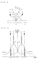
- Figs. 2 to 5 are views and diagrams describing the circumstances caused by a deviation in angle between the central axis of the measuring device body and the measurement surface of the object to be measured. It is to be noted that the angle to be formed from the normal 5n toward the right of the sheet is defined as positive and the angle to be formed from the normal 5n toward the left of the sheet is defined as negative.
- Fig. 2 is a view showing the positional relationship between the optical system and measurement surface in a case where the central axis 2n of the measuring device body 2 coincides with the normal 5n of a measurement surface 5s.
- the illumination light 11 is radiated from an illumination system L1 located in a direction tilted from the normal 5n by an angle + ⁇
- the illumination light 11 is reflected at a measurement point P of the measurement surface 5s and is received by a light receiving system R1 located in a direction tilted from the normal 5n by an angle +( ⁇ + ⁇ ) or a light receiving system R2 located in a direction tilted from the normal 5n by an angle -( ⁇ + ⁇ ).
- an illumination light 12 is radiated from an illumination system L2 located in a direction tilted from the normal 5n by an angle - ⁇ , the illumination light 12 is reflected at the measurement point P of the measurement surface 5s and is received by the light receiving system R1 or light receiving system R2.
- Fig. 3 is a graph showing reflected light intensities when the optical system and measurement surface have the positional relationship of Fig. 2 .
- the vertical line and horizontal line represent a reflected light intensity and an angle A with respect to the normal 5n.
- specularly reflected lights with respect to the illumination lights 11 and 12 from the illumination systems L1 and L2 are respectively emitted in the directions axisymmetric with the illumination lights about the normal 5n.
- the specularly reflected light with respect to the illumination light 11 is emitted in a direction where an angle of the location of the illumination system L2 is - ⁇
- the specularly reflected light with respect to the illumination light 12 is emitted in a direction where an angle of the location of the illumination system L1 is + ⁇ .
- the reflected light is generated at the positions with other angles except for the position of the center peak of the specularly reflected light
- the distribution as shown in Fig. 3 is exhibited when attention is paid to the relationship between the reflected light intensity and angle A.
- the components of reflection characteristics are of three types described below, and the reflection characteristics are determined by a sum of (i) to (iii).
- the reflected light intensity for the illumination light 11 from the illumination system L1 can be approximated to reflection characteristics R(A+ ⁇ )
- the reflected light intensity for the illumination light 12 from the illumination system L2 can be approximated to reflection characteristics R(A- ⁇ ) (see Fig. 3 ).
- the reflected light intensity at the angle ( ⁇ + ⁇ ) of the light receiving system R1 is R(+ ⁇ )
- the reflected light intensity at the angle -( ⁇ + ⁇ ) of the light receiving system R2 is R(- ⁇ )
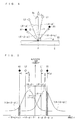
- Fig. 4 is a view showing the positional relationship between the optical system and measurement surface in a case where the central axis 2n of the measuring device body 2 is tilted in an angle - ⁇ direction with respect to the normal 5n of the measurement surface 5s.
- the central axis 2n is tilted in the angle - ⁇ direction with respect to the normal 5n
- the position of the illumination system L1 is tilted from the angle +( ⁇ ) to the angle +( ⁇ - ⁇ ) with respect to the normal 5n
- the position of the illumination system L2 is tilted from the angle -( ⁇ ) to the angle -( ⁇ + ⁇ ) with respect to the normal 5n.
- the position of the light receiving system R1 is tilted from the angle +( ⁇ + ⁇ ) to the angle +( ⁇ + ⁇ - ⁇ ) with respect to the normal 5n
- the position of the light receiving system R2 is tilted from the angle -( ⁇ + ⁇ ) to the angle -( ⁇ + ⁇ + ⁇ ) with respect to the normal 5n.
- Fig. 5 is a graph showing reflected light intensities in a case where an illumination of light is performed while the optical system and the measurement surface have the positional relationship of Fig. 4 .
- the reflected light intensity for the illumination light 11 from the illumination system L1 can be approximated to reflection characteristics R(A+( ⁇ - ⁇ ))
- the reflected light intensity for the illumination light 12 from the illumination system L2 can be approximated to reflection characteristics R(A-( ⁇ + ⁇ )).
- the reflected light intensity at the angle +( ⁇ + ⁇ - ⁇ ) of the light receiving system R1 is R( ⁇ -2 ⁇ )
- the reflected light intensity at the angle -( ⁇ + ⁇ + ⁇ ) of the light receiving system R2 is R(- ⁇ -2 ⁇ )
- the relationship of R( ⁇ -2 ⁇ ) ⁇ R(- ⁇ -2 ⁇ ) holds in shaded areas that indicate light amounts thereof.
- the light amount received by the light receiving system R1 is larger but the light amount received by the light receiving system R2 is smaller than those in the case where the central axis 2n coincides with the normal 5n (see Figs. 4 and 6 ).
- the attitude error can be reduced through a correction process involving averaging.
- the light receiving system is made common in the multi-angle colorimeter of the multidirectional illumination and unidirectional light receiving type, and the illumination system is made common in the multi-angle colorimeter of the unidirectional illumination and multidirectional light receiving type.
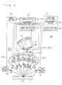
- Fig. 6 is a view showing a basic functional configuration of a multi-angle colorimeter 100 of the multidirectional illumination and unidirectional light receiving type according to a first embodiment of the present invention, which shows an example in which only optical fibers are arranged axisymmetrically and a photodetector unit (polychromator) is used in common.
- Fig. 7 is a view schematically describing an internal configuration of the photodetector unit.
- the multi-angle colorimeter 100 includes a photodetector section 40 and a control section 70.
- the photodetector section 40 includes first illumination sections 1A to 4A that are arranged on a virtual reference plane including a predetermined reference line (central axis 2n of the measuring device body 2) and perform light irradiation at different angles toward a predetermined measurement point P defined on the reference line, and second illumination sections 1B to 4B arranged symmetrically with the first illumination sections 1A to 4A, respectively, about the central axis 2n on the reference plane.
- the photodetector section 40 includes a single photodetector unit 41 and an element group for introducing the light into the photodetector unit 41.
- An optical fiber 42 is branched into two, and the lower end surfaces of the branches serve as first and second light receiving windows 5A and 5B arranged symmetrically about the central axis 2n.
- Micro lenses for efficiently focusing the reflected lights from the measurement surface on the light receiving windows 5A and 5B are arranged in front of the light receiving windows 5A and 5B.
- the first and second light receiving windows 5A and 5B are arranged on the reference plane, each of which facing the measurement point P.
- the expression "light receiving window” does not specify a particular structure by itself but can include all of the configurations for allowing the entrance of the reflected light from the measurement surface.
- the branches of the optical fiber 42 are adjacent to and parallel to each other in the upper portion thereof, upper distal ends thereof being arranged toward an entrance slit 50 of the photodetector unit 41.
- the configuration is not made so as to mix together the lights respectively from the branches of the optical fiber 42. Accordingly, the lights passing through the branches of the optical fiber 42 enter the photodetector unit 41 while being spatially separated from each other.
- the photodetector unit 41 includes a photoelectric conversion element 52 that receives first and second lights g1 and g2 respectively received by the first and second light receiving windows 5A and 5B through the optical fiber 42 and an optical path component such as an optical diffraction element described below to convert spectral components of the lights g1 and g2 into electric signals.
- a photoelectric conversion element 52 that receives first and second lights g1 and g2 respectively received by the first and second light receiving windows 5A and 5B through the optical fiber 42 and an optical path component such as an optical diffraction element described below to convert spectral components of the lights g1 and g2 into electric signals.
- the control section 70 includes a computing section 72 that determines detection values of the first and second lights g1 and g2 based on the electric signals and obtains the color information of the measurement surface located at the measurement point P based on the detection values.
- the control section 70 is provided with an operation display panel 4, a measurement switch 65, a display section 66, a memory section 60, and a measurement control section 71.
- the reference plane is a plane which includes the central axis 2n and is perpendicular to the measurement surface in a case where the central axis 2n is perpendicular to the measurement surface.
- this plane is referred to as a "main geometry surface”.
- a virtual plane which is orthogonal to the reference plane is referred to as a "sub-geometry surface”.
- the multi-angle colorimeter of the present invention employs, for the tilt of the measurement surface regarding the direction parallel to the main geometry surface, the symmetrical arrangement in illumination and light receiving.
- Each of the first illumination sections 1A to 4A and second illumination sections 1B to 4B is comprised of, for example, a light source formed of a xenon flash lamp, a regulating plate that regulates a light beam from the light source, and a collimator lens (not shown).
- Light emitting circuits 11A to 14A and 11B to 14B that cause the light source to emit light are provided near the first illumination sections 1A to 4A and second illumination sections 1B to 4B, respectively.
- the first illumination sections 1A to 4A and the second illumination sections 1B to 4B are arranged to be positioned axisymmetrically about the central axis 2n, where the arrangements of 15 degrees, 45 degrees, and 110 degrees and the arrangements of 25 degrees, 45 degrees, and 75 degree are included.
- a pair of the first illumination section 2A and second illumination section 2B, a pair of the first illumination section 3A and second illumination section 3B, and a pair of the first illumination section 4A and second illumination section 4B are each arranged to be positioned symmetrically about the central axis 2n.
- the illumination section 4A (4B) arranged on the central axis 2n serves as both of the first illumination section 4A and second illumination section 4B.
- the light emitting circuits 11A to 14A and 11B to 14B each include, for example, a main capacitor for applying a high DC voltage of several hundred volts to an electrode of the light source, a charging circuit for charging the main capacitor, and a trigger generating circuit for applying a high AC voltage of several ten thousand volts to the trigger electrode formed of a metal wire wound in close contact with the light source. Further, the light emitting circuits 11A to 14A and 11B to 14B each include a semiconductor switch element formed of, for example, an IGBT and a drive circuit for applying a drive voltage to the semiconductor switch element.
- a high AC voltage is momentarily applied to the trigger electrode through a trigger transformer by a trigger capacitor of the trigger generating circuit, whereby the light source is triggered. Accordingly, a DC current flows from the main capacitor, which causes light emission. Then, the semiconductor switch is turned off at a desired timing, so that light emission can be stopped.
- the regulating plate is arranged such that an opening of the regulating plate coincides with a focal point of the collimator lens, and a light beam from the light source which has passed through the opening of the regulating plate is collimated by the collimator lens to turn into a parallel beam, which illuminates the measurement point P of the object to be measured 5.
- the photodetector section 40 includes the first and second light receiving windows 5A and 5B that converge the parallel beams from the measurement point P of the object to be measured 5, and optical fibers 42-1 and 42-2 located at imaging positions of the first and second light receiving windows 5A and 5B.
- the photodetector section 40 guides the incoming light beams to the single photodetector unit 41 through the optical fibers 42-1 and 42-2. Then, the photodetector unit 41 separates the incoming light beams per wavelength and outputs the spectral data corresponding to the light intensity.
- the single photodetector unit 41 includes a concave diffraction grating 51 and two line sensors (one-dimensional photoelectric conversion elements) 52-1 and 52-2, and, as shown in Fig. 7 , entrance slits 50-1 and 50-2 of the photodetector unit 41 are arranged perpendicularly to the dispersion direction of the concave diffraction grating 51.
- the lights respectively emitted from the fibers 42-1 and 42-2 enter different areas of the concave diffraction grating 51 and are diffracted and reflected independently of each other.
- the resulting diffracted lights extend along the dispersion direction of the concave diffraction grating 51 and are received by two line sensors 52-1 and 52-2 arranged in the direction perpendicular to the dispersion direction. Then, the first and second lights g1 and g2 are converted into electric signals by the two line sensors 52-1 and 52-2, respectively.
- the concave diffraction grating 51 is shared by the first and second lights g1 and g2.
- the dispersion direction of the concave diffraction grating 51 is the direction along the surface of the drawing, and the direction perpendicular to the dispersion direction is the depth direction of the surface with respect to the drawing.
- the optical fiber 42 functions as a light guide section that provides the first and second lights respectively entering from the light receiving windows 5A and 5B to the photoelectric conversion elements 52-1 and 52-2 from the light receiving windows 5A and 5B in a parallel manner while those lights are spatially separated.
- the light guide mode of this embodiment is a mode of spatially separating lights.
- the operation display panel 4 includes the measurement switch 65 for giving an instruction to start measurement, the display section 66 formed of, for example, a liquid crystal display panel for displaying measurement results, and the like.
- the memory section 60 is comprised of an RAM, an EEPROM, and the like and temporarily saves the measurement results and the like.
- the memory section 60 also stores a control program for operating the control section 70 as follows.
- the control section 70 includes an electronic circuit such as a CPU or A/D converter, includes the measurement control section 71 and the calculating section 72 as a functional block, and controls an operation of each section of the multi-angle colorimeter 100 in accordance with the control program stored in the memory section 60.
- an electronic circuit such as a CPU or A/D converter
- the measurement control section 71 When the measurement switch 65 is operated, the measurement control section 71 causes respective light sources of the first illumination sections 1A to 4A and second illumination sections 1B to 4B to time-sequentially emit light to measure the color. Moreover, the measurement control section 71 causes the display section 66 to display calculation results obtained by the computing section 72 as the measurement results.
- the computing section 72 respectively determines detection values of the first and second light (spectral reflection characteristics) based on the electrical signals converted by the photodetector section 40 and obtains the color information (for example, tristimulus values) of the measurement surface located at the measurement point P based on the detection values.
- the illumination sections 1A to 4A and 1B to 4B are caused to time-sequentially emit light, the resulting lights reflected on the measurement surface are received through the light receiving windows 5A and 5B, and those lights are guided to the photodetector unit 41 to be diffracted and dispersed.
- This enables the single photodetector unit 41 to perform light dispersion and light detection for color evaluations in a multi-angle mode as well as a symmetrical arrangement mode.
- light dispersion is enabled by the single concave diffraction grating 51.
- the single photodetector unit 41 is shared by (serves as) two symmetrical measurement systems, whereby a detection error due to an individual difference in characteristics of the two photodetector units can be prevented, differently from the case where photodetector units are individually provided to two measurement systems.
- Fig. 8 shows graphs showing experimental results by a device corresponding to the multi-angle colorimeter 100 of the first embodiment and a conventional device that does not have a symmetrical arrangement.
- Fig. 8(a) to Fig. 8(c) show the results in cases of the arrangements of 15 degrees (see Fig. 8(a) ), 45 degrees (see Fig. 8(b) ), and 110 degrees (see Fig. 8(c) ), respectively, which are aspecular angles of the optical arrangements (geometries) recommended in ASTME2194 being the primary standard in the evaluation methods for metallic coating and pear color coating.
- the vertical line and horizontal line represent a color difference ⁇ E as a measurement error in the L*a*b* colorimetric system and a deviated angle between the central axis 2n and normal 5n.
- a measured value error is kept smaller compared with the case in which a symmetrical arrangement is not provided (in the above-mentioned case, "without correction” is added), leading to an effect that the measurement stability is improved.
- the device can be downsized thanks to the photodetector unit 41 being shared.
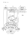
- Fig. 9 is a view showing a basic functional configuration of a multi-angle colorimeter 100a configured to switch the optical paths of two systems on the light receiver in terms of time, as a first modification of the multi-angle colorimeter 100 in Fig. 6 .
- the multi-angle colorimeter 100a differs from the multi-angle colorimeter 100 of Fig. 6 in that, in a photodetector section 40a, a single line sensor (photoelectric conversion element) 52a is provided and the shutters SA and SB are provided near the first and second light receiving windows 5A and 5B, respectively.
- a bundle fiber 42a of Fig. 9 is a bundle fiber that combines lights in the entrance slit 50 while the optical fiber 42 of Fig. 6 is a fiber including two independent fibers spatially separated in the entrance slit 50.
- the other configuration is similar to that of the multi-angle colorimeter 100 of Fig. 6 (see Fig. 9 ).
- the mechanical or optical shutters SA and SB are respectively provided, on the front surface sides of the first and second light receiving windows 5A and 5B, to the entrance opening of the bundle fiber 42a with two branches on the entrance side and one branch on the exit side that guides the light to the light receiving system. This enables on-off control corresponding to selective passing-through/interception of the lights of two systems.
- the shutters SA and SB openable and closable are provided to the entrance opening of the fiber 42 in this manner, so that one shutter is closed with the other shutter open, which prevents a contribution to the measured values. This achieves the configuration in which the single line sensor 52a is provided in the photodetector unit 41a.
- the shutters SA and SB and a drive section (such as small-sized motor) that selectively drives those function as a light guide section that time-divides the lights from the first and second light receiving windows 5A and 5B and selectively provides the lights to the photoelectric conversion elements.
- Fig. 10 is a view showing a basic functional configuration of a multi-angle colorimeter 100b configured to switch the optical paths of two systems on the light receiver in terms of time, as a second modification of the multi-angle colorimeter 100 of Fig. 6 .
- the multi-angle colorimeter 100b differs from the multi-angle colorimeter 100 of Fig.
- a single line sensor 52b is provided in the photodetector unit 41b
- a diffusing plate BD is provided at the position of the entrance slit 50 on the external side of the photodetector unit 41b
- movable mirrors MA and MB are provided near the first and second light receiving windows 5A and 5B, respectively
- light traps TA and TB are provided near the photodetector unit 41.
- the other configuration is similar to that of the multi-angle colorimeter 100 of Fig. 6 (see Fig. 10 ).
- the movable mirrors MA and MB are selectively rotated by, for example, a drive section such as a motor such that the movable mirrors MA and MB are selectively caused to form an angle for reflecting the light toward the photodetector unit 41b.
- the photodetector section 40b is capable of the control to time-sequentially switch the optical paths of the measured lights respectively received by the first and second light receiving windows 5A and 5B and disperse the measured lights.
- a first light g1 passing through the first light receiving window 5A is reflected on the movable mirror MA, and while it is intercepted by the light trap TA, the second light g2 passing through the second light receiving window 5B is reflected on the movable mirror MB and enters the entrance slit 50 through the diffusing plate BD (see Fig. 10 ).
- a first light g2 passing through the second light receiving window 5B is reflected on the movable mirror MB, and while it is intercepted by the light trap TB, the first light g1 passing through the first light receiving window 5A is reflected on the movable mirror MA and enters the entrance slit 50 through the diffusing plate BD.
- time-division light receiving is realized by the provision of the movable mirrors MA and MB, which are arranged on the optical paths of the lights respectively entering from the first and second light receiving windows 5A and 5B, and the drive section, which selectively directs the reflection directions of the lights respectively reflected on the movable mirrors MA and MB toward the photodetector unit 41 b.
- the configuration is made such that the reflected lights from the measurement point P are guided to the photodetector unit 41 b using the movable mirrors MA and MB, that is, such that the angles of the movable mirrors MA and MB are adjusted to allow one of the lights to enter, for example, the light trap TA or TB while the other of the lights is guided toward the photodetector unit 41b to avoid any impact on a measurement value.
- This realizes such a configuration that a single line sensor 52b is provided in the photodetector unit 41b.
- control section 70 automatically executes this operation in accordance with the program stored in the memory section 60.
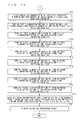
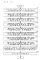
- Figs. 11 and 12 are flowcharts illustrating a flow of an operation realized by the multi-angle colorimeter 100a. The individual functions of the sections have been descried above, and thus, only an overall flow is described here. First, all the illuminations are turned off in starting a measurement, and then, the process moves to Step S1.
- Step S1 the measurement control section 71 causes the shutter SA corresponding to the first light receiving window 5A to open and the shutter SB corresponding to the second light receiving window 5B to close.
- Step S2 the measurement control section 71 causes the first illumination section 1A to turn on, the photodetector section 40a detects the first light g1 through the first light receiving window 5A, the computing section 72 obtains a first light detection value D1A, and the memory section 60 stores the first light detection value D1A.
- Step S3 the measurement control section 71 causes the first illumination section 1A to turn off and the first illumination section 2A to turn on, the photodetector section 40a detects the first light g1 through the first light receiving window 5A, the computing section 72 obtains a first light detection value D2A, and the memory section 60 stores the first light detection value D2A.
- Step S4 the measurement control section 71 causes the first illumination section 2A to turn off and the first illumination section 3A to turn on, the photodetector section 40a detects the first light g1 through the first light receiving window 5A, the computing section 72 obtains a first light detection value D3A, and the memory section 60 stores the first light detection value D3A.
- Step S5 the measurement control section 71 causes the first illumination section 3A to turn off and the first illumination section 4A to turn on, the photodetector section 40a detects the first light g1 through the first light receiving window 5A, the computing section 72 obtains a first light detection value D4A, and the memory section 60 stores the first light detection value D4A.
- Step S6 the measurement control section 71 causes the first illumination section 4A to turn off and the second illumination section 4B to turn on, the photodetector section 40a detects the first light g1 through the first light receiving window 5A, the computing section 72 obtains a first light detection value D4B, and the memory section 60 stores the first light detection value D4B.
- Step S7 the measurement control section 71 causes the second illumination section 4B to turn off and the second illumination section 3B to turn on, the photodetector section 40a detects the first light g1 through the first light receiving window 5A, the computing section 72 obtains a first light detection value D3B, and the memory section 60 stores the first light detection value D3B.
- Step S8 the measurement control section 71 causes the second illumination section 3B to turn off and the second illumination section 2B to turn on, the photodetector section 40a detects the first light g1 through the first light receiving window 5A, the computing section 72 obtains a first light detection value D2B, and the memory section 60 stores the first light detection value D2B.
- Step S9 the measurement control section 71 causes the second illumination section 2B to turn off and the second illumination section 1B to turn on, the photodetector section 40a detects the first light g1 through the first light receiving window 5A, the computing section 72 obtains a first light detection value D1B, and the memory section 60 stores the first light detection value D1B. After that, the second illumination section 1B is turned off.
- Step S10 the measurement control section 71 causes the shutter SA corresponding to the first light receiving window 5A to close and the shutter SB corresponding to the second light receiving window 5B to open.
- Step S11 the measurement control section 71 causes the second illumination section 1B to turn off and the first illumination section 1A to turn on, the photodetector section 40a detects the second light g2 through the second light receiving window 5B, the computing section 72 obtains a second light detection value V1A, and the memory section 60 stores the second light detection value V1A.
- Step S12 the measurement control section 71 causes the first illumination section 1A to turn off and the first illumination section 2A to turn on, the photodetector section 40a detects the second light g2 through the second light receiving window 5B, the computing section 72 obtains a second light detection value V2A, and the memory section 60 stores the second light detection value V2A.
- Step S13 the measurement control section 71 causes the first illumination section 2A to turn off and the first illumination section 3A to turn off, the photodetector section 40a detects the second light g2 through the second light receiving window 5B, the computing section 72 obtains a second light detection value V3A, and the memory section 60 stores the second light detection value V3A.
- Step S14 the measurement control section 71 causes the first illumination section 3A to turn off and the first illumination section 4A to turn on, the photodetector section 40a detects the second light g2 through the second light receiving window 5B, the computing section 72 obtains a second light detection value V4A, and the memory section 60 stores the second light detection value V4A.
- Step S 15 the measurement control section 71 causes the first illumination section 4A to turn off and the second illumination section 4B to turn on, the photodetector section 40a detects the second light g2 through the second light receiving window 5B, the computing section 72 obtains a second light detection value V4B, and the memory section 60 stores the second light detection value V4B.
- Step S16 the measurement control section 71 causes the second illumination section 4B to turn off and the second illumination section 3B to turn on, the photodetector section 40a detects the second light g2 through the second light receiving window 5B, the computing section 72 obtains a second light detection value V3B, and the memory section 60 stores the second light detection value V3B.
- Step S 17 the measurement control section 71 causes the second illumination section 3B to turn off and the second illumination section 2B to turn on, the photodetector section 40a detects the second light g2 through the second light receiving window 5B, the computing section 72 obtains a second light detection value V2B, and the memory section 60 stores the second light detection value V2B.
- Step S18 the measurement control section 71 causes the second illumination section 2B to turn off and the second illumination section 1B to turn off, the photodetector section 40a detects the second light g2 through the second light receiving window 5B, the computing section 72 obtains a second light detection value V1B, and the memory section 60 stores the second light detection value V1B. After that, the second illumination section 1 B is turned off and the shutter SB is closed.
- Step S 19 the computing section 72 calculates the color information of the measurement surface located at the measurement point P based on the first light detection values D1A to D4A and D1B to D4B and second light detection values V1A to V4A and V1B to V4B stored in the memory section 60.
- Step S 19 the color information of the measurement point P is obtained based on a total of 14 measured values obtained by multiplying seven illuminations of the first and second illumination sections (where the first illumination section 4A and second illumination section 4B refer to the same element) by two light receptions by the first and second light receiving windows. Specifically, based on the detection values of the first and second lights of each pair of:
- Step S20 the measurement control section 71 causes the display section 66 to display, as a measurement result, the color information of the measurement surface located at the measurement point P which has been calculated by the computing section 72. Accordingly, this operational flow is finished.
- the multi-angle colorimeter of the multidirectional illumination and unidirectional light receiving type has the configuration in which the photodetector unit is made common as shown in Fig. 6 and the photodetector unit is made common and the optical path is switched as shown in Figs. 9 and 10 .
- This enables to measure the color based on the information of the reflected light obtained with a symmetrical optical arrangement, allowing appropriate color measurement even if the central axis 2n of the measuring device body 2 is tilted from the normal 5n of the sample surface in the reference plane.
- the single photodetector unit 41 (41a, 41 b) detects the first and second lights g1 and g2 received through the first and second light receiving windows 5A and 5B, which enables to reduce the size of the colorimeter, resulting in a reduction in cost thereof.
- the single photodetector unit 41 (41a, 41 b) is used in common, whereby internal parts thereof can be used in common. This eliminates the need to take into account an individual difference between photodetector units that is caused in a case where multiple photodetector units are used.
- FIG. 13 is a view showing a basic functional configuration of the multi-angle colorimeter 100c of the multidirectional illumination and unidirectional light receiving type in a second embodiment of the present invention.
- This embodiment differs from the first embodiment in the employment of the configuration in which the photodetector unit is not provided in common but two photodetector units are provided, with one of the photodetector units being simplified. It is to be noted that the other configuration is similar to the device of the first embodiment, and thus, only differences therebetween are described here (see Fig. 13 ).
- the configuration of the multi-angle colorimeter 100c includes a photodetector section 40c including a first photodetector unit 41c and a second photodetector unit 41p, and the computing section 72.
- the first photodetector unit 41c includes a first photoelectric conversion element (linear sensor) 52A that receives a first light g1 received through the first light receiving window 5A and converts the first light g1 into an electric signal.
- the second photodetector unit 41p includes a second photoelectric conversion element 52B that receives a second light g2 received through the second light receiving window 5B and converts the second light g2 into an electric signal.
- the computing section 72 determines detection values of the first and second lights g1 and g2 based on the signals and obtains the color information of the measurement surface located at the measurement point P based on the detection values.
- a photodetector unit having a lower wavelength resolution than that of the first photodetector unit 41c is used as the second photodetector unit 41p.
- Examples of the second photodetector unit 41p having a lower wavelength resolution than that of the first photodetector unit 41 c include:
- the linear sensor 52 similar to one used in, for example, the photodetector unit 41 of Fig. 7 is used as the first photodetector unit 41c including the first photoelectric conversion element 52A, and for example, a silicon photodiode (SPD) is used as the second photodetector unit 41p including the second photoelectric conversion element 52B.
- SPD silicon photodiode
- the first photoelectric conversion element 52A and the second photoelectric conversion element 52B can each obtain a value of a brightness parameter L*. An average value of those values is calculated to determine a correction factor, whereby an attitude error can be reduced.
- Fig. 14 is a graph showing, together with the experimental results of Fig. 8 , experimental results obtained in a case where corrections have been made to an attitude error by a symmetrical arrangement using only a brightness parameter L* indicating a brightness with the highest error sensitivity as in the second embodiment, where similarly to Fig. 8 , the L*a*b* colorimetric system is taken as an example.
- Fig. 14(a) to Fig. 14(f) respectively show the results in cases of the arrangements of 15 degrees (see Fig. 14(a) and (d) ), 45 degrees (see Fig. 14(b) and (e) ), and 110 degrees (see Fig.
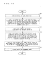
- Fig. 15 is a flowchart illustrating a flow of the operation realized by the multi-angle colorimeter 100c.
- the individual functions of the sections have been described above, and thus, only an overall flow is described here.
- Step ST1 all the illuminations are turned off in starting a measurement, and then, the process moves to Step ST1.
- Step ST1 the measurement control section 71 causes the first illumination section 1A to turn on, the photodetector section 40c detects a first light g1 by the first photoelectric conversion element 52A through the first light receiving window 5A, and the computing section 72 obtains a first light detection value D1A. At the same time, the photodetector section 40c detects a second light g2 by the second photoelectric conversion element 52B through the second light receiving window 5B, and the computing section 72 obtains a first light detection value V1A. Then, the memory section 60 stores those values.
- Step ST2 the measurement control section 71 causes the first illumination section 1A to turn off and the first illumination section 2A to turn on, the photodetector section 40c detects the first light g1 by the first photoelectric conversion element 52A through the first light receiving window 5A, and the computing section 72 obtains a first light detection value D2A. At the same time, the photodetector section 40c detects the second light g2 by the second photoelectric conversion element 52B through the second light receiving window 5B, and the computing section 72 obtains a first light detection value V2A. Then, the memory section 60 stores those values.
- Step ST3 the measurement control section 71 causes the first illumination section 2A to turn off and the first illumination section 3A to turn on, the photodetector section 40c detects the first light g1 by the first photoelectric conversion element 52A through the first light receiving window 5A, and the computing section 72 obtains a first light detection value D3A. At the same time, the photodetector section 40c detects the second light g2 by the second photoelectric conversion element 52B through the second light receiving window 5B, and the computing section 72 obtains a first light detection value V3A. Then, the memory section 60 stores those values.
- Step ST4 the measurement control section 71 causes the first illumination section 3A to turn off and the first illumination section 4A to turn on, the photodetector section 40c detects the first light g1 by the first photoelectric conversion element 52A through the first light receiving window 5A, and the computing section 72 obtains a first light detection value D4A. At the same time, the photodetector section 40c detects the second light g2 by the second photoelectric conversion element 52B through the second light receiving window 5B, and the computing section 72 obtains a first light detection value V4A. Then, the memory section 60 stores those values.
- Step ST5 the measurement control section 71 causes the first illumination section 4A to turn off and the second illumination section 4B to turn on, the photodetector section 40c detects the first light g1 by the first photoelectric conversion element 52A through the first light receiving window 5A, and the computing section 72 obtains a second light detection value D4B. At the same time, the photodetector section 40c detects the second light g2 by the second photoelectric conversion element 52B through the second light receiving window 5B, and the computing section 72 obtains a second light detection value V4B. Then, the memory section 60 stores those values.
- Step ST6 the measurement control section 71 causes the second illumination section 4B to turn off and the second illumination section 3B to turn on, the photodetector section 40c detects the first light g1 by the first photoelectric conversion element 52A through the first light receiving window 5A, and the computing section 72 obtains a second light detection value D3B. At the same time, the photodetector section 40c detects the second light g2 by the second photoelectric conversion element 52B through the second light receiving window 5B, and the computing section 72 obtains a second light detection value V3B. Then, the memory section 60 stores those values.
- Step ST7 the measurement control section 71 causes the second illumination section 3B to turn off and the second illumination section 2B to turn on, the photodetector section 40c detects the first light g1 by the first photoelectric conversion element 52A through the first light receiving window 5A, and the computing section 72 obtains a second light detection value D2B. At the same time, the photodetector section 40c detects the second light g2 by the second photoelectric conversion element 52B through the second light receiving window 5B, and the computing section 72 obtains a second light detection value V2B. Then, the memory section 60 stores those values.
- Step ST8 the measurement control section 71 causes the second illumination section 2B to turn off and the second illumination section 1B to turn on, the photodetector section 40c detects the first light g1 by the first photoelectric conversion element 52A through the first light receiving window 5A, and the computing section 72 obtains a second light detection value D1B. At the same time, the photodetector section 40c detects the second light g2 by the second photoelectric conversion element 52B through the second light receiving window 5B, and the computing section 72 obtains a second light detection value V1B. Then, the memory section 60 stores those values. After that, the second illumination section 1B is turned off.
- Step ST9 the computing section 72 calculates the color information of the measurement surface located at the measurement point P based on the first light detection values D1A to D4A and D1B to D4B and second light detection values V I A to V4A and V1B to V4B stored in the memory section 60.
- Step ST9 the color information of the measurement point P is obtained based on a total of 14 measured values obtained by multiplying seven illuminations of the first and second illumination sections (where the first illumination section 4A and second illumination section 4B refer to the same element) by two light receptions by the first and second light receiving windows. Specifically, based on the detection values of the first and second lights of each pair of:
- Step ST10 the measurement control section 71 causes the display section 66 to display, as a measurement result, the color information of the sample surface located at the measurement point P which has been calculated by the computing section 72. Accordingly, this operational flow is finished.
- the multi-angle colorimeter 100c of the multidirectional illumination and unidirectional light receiving type in the second embodiment uses, as the second photodetector unit 41p, a photodetector unit having a lower wavelength resolution than that of the first photodetector unit 41c. This eliminates the need to output unnecessary spectral data, which lowers a cost, achieving a colorimeter having a compact configuration.
- Fig. 16 is a view showing a basic functional configuration of a multi-angle colorimeter 100d of the unidirectional illumination and multidirectional light receiving type in a third embodiment of the present invention.
- This embodiment differs from the first embodiment in that the configuration is made such that the photodetector unit and illumination section are arranged in opposite positions.
- the other configuration is similar to that of the device of the first embodiment, and thus, only differences are described here (see Fig. 16 ).
- the multi-angle colorimeter 100d of the unidirectional illumination and multidirectional light receiving type mainly includes:
- the photoelectric conversion elements 21A to 24A and the photoelectric conversion elements 21B to 24B are arranged at positions symmetrical about the central axis 2n, where the arrangements of 15 degrees, 45 degrees, and 110 degrees and the arrangements of 25 degrees, 45 degrees, and 75 degrees are included. Those degrees are aspecular angles of optical arrangements (geometries) recommended in ASTME2194 and DIN6175-2 (2001) being two main standards in evaluation methods for metallic coating and pearl color coating.
- pairs of the photoelectric conversion elements 21A and 21B, photoelectric conversion elements 22A and 22B, photoelectric conversion elements 23A and 23B, and photoelectric conversion elements 24A and 24B are each arranged to be positioned symmetrically about the central axis 2n. Accordingly, the same element functions as the photoelectric conversion elements 24A and 24B.
- the photoelectric conversion elements 21A to 24A and 21B to 24B cause the reflected light beams from the measurement point P of the object to be measured 5 to enter a light receptor RV through the diffusing plate BD and are comprised of an X sensor SX, a Y sensor SY, and a Z sensor SZ that have spectral sensitivities respectively corresponding to color matching functions x( ⁇ ), y( ⁇ ), and z( ⁇ ).
- the X sensor SX, Y sensor SY, and Z sensor SZ convert incoming light beams EL (here, first and second lights g1 and g2) into electric signals corresponding to the XYZ component values in an XYZ color system.
- Fig. 17 is a flowchart illustrating a flow of the operation realized by the multi-angle colorimeter 100d.
- the individual functions of the sections have been described above, and thus, only an overall flow is described here.
- the photoelectric conversion element located in the direction coinciding with the central axis 2n of the measuring device body 2 is referred to as photoelectric conversion element 24A.
- the light source 25 is turned off in starting a measurement, and then, the process moves to Step SP1.
- Step SP1 the measurement control section 71 causes the shutter SA to open and the shutter SB to close.
- Step SP2 the measurement control section 71 causes the light source 25 to emit light through the light emitting circuit 250, whereby the first illumination section 25A turns on. Then, the photodetector section 40d detects a first light g1 through the photoelectric conversion elements 21A to 24A and 21B to 23B, the computing section 72 obtains first light detection values D1A to D4A and D1B to D3 B, and the memory section 60 stores those values.
- Step SP3 the measurement control section 71 causes the light source 25 to turn off through the light emitting circuit 25, the shutter SA to close, and the shutter SB to open.
- Step SP4 the measurement control section 71 causes the light source 25 to emit light through the light emitting circuit 25, whereby the second illumination section 25B turns on. Then, the photodetector section 40d detects a second light g2 through the photoelectric conversion elements 21A to 24A and 21B to 23B, the computing section 72 obtains second light detection values V1A to V4A and V1B to V3B, and the memory section 60 stores those values. After that, the shutter SB is closed.
- Step SP5 the computing section 72 calculates the color information of the measurement surface located at the measurement point P based on the first light detection values D1A to D4A and D1B to D4B and second light detection values V1A to V4A and V1B to V4B stored in the memory section 60.
- Step SP5 the color information of the measurement point P is obtained based on a total of 14 measured values obtained by multiplying two illuminations of the first and second illumination sections 25A and 25B by seven light receptions by the photoelectric conversion elements. Specifically, based on the detection values of the first and second lights of each pair of:
- Step SP6 the measurement control section 71 causes the display section 66 to display, as a measurement result, the color information of the measurement surface located at the measurement point P calculated by the computing section 72, and then, this operational flow is finished.
- the multi-angle colorimeter 100d of the unidirectional illumination and multidirectional light receiving type in the third embodiment measures the color based on the information of the reflected lights obtained from a symmetrical optical arrangement, so that the color can be measured appropriately even if the central axis 2n of the measuring device body 2 is tilted from the normal 5n of the sample surface in the reference plane.
- the light source 25 is shared between the first illumination section 25A and the second illumination section 25B, which downsizes a colorimeter, resulting in a lower cost. Further, the light source 25 is shared, which eliminates the need to take into account an individual difference between the light sources that occurs in a case where multiple light sources are used.
- Fig. 18 is a view showing a basic functional configuration of a multi-angle colorimeter 100e of the unidirectional illumination and multidirectional light receiving type in a fourth embodiment of the present invention.
- This embodiment differs from the third embodiment in that the configuration is made such that in the multi-angle colorimeter 100d of Fig. 16 , the photoelectric conversion elements 21A to 24A (or 21B to 24B) among the multiple pairs that constitute pairs of the photoelectric conversion elements 21A to 24A and 21B to 24B are formed of first photoelectric conversion elements and the other photoelectric conversion elements 21B to 23B (or 21A to 23A) among the multiple pairs of photoelectric conversion elements are formed of second photoelectric conversion elements.
- the photodetector unit including the second photoelectric conversion elements has a lower wavelength resolution than that of the photodetector unit including the first photoelectric conversion elements.
- the other configuration is similar to that of the device of the third embodiment, and thus, only differences are described here (see Fig. 18 ).
- the photodetector unit (polychromator) 41 of Fig. 6 is used as the photodetector unit including the first photoelectric conversion elements and the SPD of Fig. 13 is used as the photodetector unit including the second photoelectric conversion elements.
- Fig. 19 is a flowchart illustrating a flow of the operation realized by the multi-angle colorimeter 100e.
- the individual functions of the sections have been described above, and thus, only an overall flow is described here.
- Step SE1 all the illuminations are turned off in starting a measurement, and then, the process moves to Step SE1.
- Step SE1 the measurement control section 71 causes the shutter SA to open and the shutter SB to close.
- Step SE2 the measurement control section 71 causes the light source 25 to emit light through the light emitting circuit 25, whereby the first illumination section 25A turns on. Then, the photodetector section 40e detects a first light g1 through the first photoelectric conversion elements 21 A to 24A, the computing section 72 obtains first light detection values D1A to D4A. At the same time, the photodetector section 40e detects the first light g1 through the photoelectric conversion elements 21B to 23B, and the computing section 72 obtains first light detection values D1B to D3B. Then, the memory section 60 stores those values.
- Step SE3 the measurement control section 71 causes the light source 25 to turn off through the light emitting circuit 25, the shutter SA to close, and the shutter SB to open.
- Step SE4 the measurement control section 71 causes the light source 25 to emit light through the light emitting circuit 25, whereby the second illumination section 25B turns on. Then, the photodetector section 40e detects a second light g2 through the first photoelectric conversion elements 21A to 24A, and the computing section 72 obtains second light detection values V1A to V4A. At the same time, the photodetector section 40e detects the second light g2 through the second photoelectric conversion elements 21B to 23B, and the computing section 72 obtains second light detection values V1B to V3B. Then, the memory section 60 stores those values. After that, the light source 25 is turned off and the shutter SB is closed.
- Step SE5 the computing section 72 calculates the color information of the measurement surface located at the measurement point P based on the first light detection values D1A to D4A and D1B to D4B and second light detection values V1A to V4A and V1B to V4B stored in the memory section 60.
- Step SE5 the color information of the measurement point P is obtained based on a total of 14 measured values obtained by multiplying two illuminations of the first and second illumination sections 25A and 25B by seven received lights of the first photoelectric conversion elements and second photoelectric conversion elements. Specifically, based on the detection values of the first and second lights of each pair of:
- Step SE6 the measurement control section 71 causes the display section 66 to display, as a measurement result, the color information of the measurement surface located at the measurement point P calculated by the computing section 72, and then, this operational flow is finished.
- the multi-angle colorimeter 100e uses, as the photodetector unit including the second photoelectric conversion elements 21B to 23B, a photodetector unit having a lower wavelength resolution than that of the photodetector unit including the first photoelectric conversion elements 21A to 24A. This eliminates the need to output unnecessary spectral data, which lowers a cost, realizing a colorimeter having a compact configuration.
- the second embodiment has described the case of the spectral luminous efficiency V( ⁇ ) as photosensitivity characteristics, other photosensitivity characteristics may be used. For example, using a bandpass filter having a sharp peak at a specific wavelength, only an output having a certain single wavelength may be monitored by the second photoelectric conversion element 52B, and a measured value may be corrected by the output.
- the photodetector unit positioned in the direction coinciding with the central axis 2n of the measuring device body 2 is the photodetector unit including a first photoelectric conversion element 34A in the fourth embodiment, which may be used as the photodetector unit including the second photoelectric conversion element having a lower wavelength resolution than that of the photodetector unit including the first photoelectric conversion element.
- One configuration of the multi-angle colorimeter described above includes (a) multiple first illumination sections that are arranged on a virtual reference plane including a predetermined reference line and perform light irradiation at different angles toward a predetermined measurement point defined on the reference line, (b) multiple second illumination sections that are respectively arranged symmetrically with the multiple first illumination sections about the reference line on the reference plane and perform light irradiation toward the predetermined measurement point, (c) a photodetector section including: first and second light receiving windows arranged on the reference plane, face the measurement point, and are arranged symmetrically about the reference line; and a single photodetector unit including a photoelectric conversion element that receives first and second lights respectively received through the first and second light receiving windows and converts the received lights into electric signals, and (d) a computing section that determines detection values of the first and second lights based on the signals and obtains color information of a measurement surface located at the measurement point based on the detection values.
- the photodetector unit includes a single light dispersing element and first and second photoelectric conversion elements, and the multi-angle colorimeter further includes a light guide section that spatially separates the first and second lights and provides the first and second lights to the first and second photoelectric conversion elements from the first and second light receiving windows, respectively, through the light dispersing element.
- the multi-angle colorimeter includes a light guide section that time-divides the first and second lights and provides the first and second lights to the photoelectric conversion element.
- the light guide section includes first and second light guide elements in which the first and second light receiving windows are respectively defined at one ends thereof, and an opening and closing section that selectively opens and closes optical paths of the first and second lights toward the first and second light receiving windows.
- the light guide section includes an optical path switching section that selectively provides the first and second lights entering through the first and second light receiving windows to the photodetector unit.
- the optical path switching section includes first and second mirrors arranged on optical paths from the first and second light receiving windows, respectively, and a drive section that selectively directs reflection directions of the first and second lights from the first and second mirrors toward the photodetector unit.
- Another configuration of the multi-angle colorimeter described above includes (a) multiple first illumination sections that are arranged on a virtual reference plane including a predetermined reference line and perform light irradiation at different angles toward a predetermined measurement point defined on the reference line, (b) multiple second illumination sections that are respectively arranged symmetrically with the multiple first illumination sections about the reference line on the reference plane and perform light irradiation toward the predetermined measurement point, (c) a photodetector section including: first and second light receiving windows arranged on the reference plane, face the measurement point, and are arranged symmetrically about the reference line; a first photodetector unit including a first photoelectric conversion element that receives a first light received through the first light receiving window and converts the first light into an electric signal; and a second photodetector unit including a second photoelectric conversion element that receives a second light received through the second light receiving window and converts the second light into an electric signal, and (d) a computing section that determines detection values of the first and second lights based
- Still another configuration of the multi-angle colorimeter described above includes (a) a first illumination section that is arranged on a virtual reference plane including a predetermined reference line and performs light irradiation at a predetermined angle toward a predetermined measurement point defined on the reference line, (b) a second illumination section that is arranged symmetrically with the first illumination section about the reference line on the reference plane and performs light irradiation toward the measurement point, (c) a photodetector section including multiple pairs of photoelectric conversion elements that are arranged symmetrically about the reference line on the reference plane, each of the multiple pairs facing the measurement point, and (d) a computing section that obtains color information of a measurement surface located at the measurement point based on detection values respectively obtained from photoelectric conversion signals of the multiple pairs of photoelectric conversion elements, wherein the first illumination section and the second illumination section share a light source.
- the first illumination section includes a first light guide section that receives a first portion of a light from the light source and guides the first portion toward the measurement point, a second light guide section that receives a second portion of the light from the light source and guides the second portion toward the measurement point, and an opening and closing section that selectively opens and closes exits of the first portion and the second portion of the light guided by the first light guide section and the second light guide section.
- One photoelectric conversion element of each of the multiple pairs of photoelectric conversion elements is formed of a first photoelectric conversion element
- the other photoelectric conversion element of each of the multiple pairs of photoelectric conversion elements is formed of a second photoelectric conversion element
- a photodetector unit including the second photoelectric conversion elements has a lower wavelength resolution than that of a photodetector unit including the first photoelectric conversion elements.
- the multi-angle colorimeter described above measures the color based on the information of the reflected lights achieved from a symmetrical optical arrangement, which enables to appropriately measure the color even if the reference line is tilted from the normal of the sample surface in the reference plane.
- a single photodetector unit detects the first and second lights received through the first and second light receiving windows, which reduces the size of a colorimeter, resulting in a lower cost thereof.
- a single photodetector unit is used in common, whereby internal parts thereof can be used in common. This eliminates the need to take into account an individual difference between photodetector units that occurs in a case where multiple photodetector units are used.
- a photodetector unit having a lower wavelength resolution than that of a first photodetector unit is used as a second photodetector unit, which lowers cost, realizing a colorimeter having a compact configuration.
- the color is measured based on the information of the reflected lights obtained from a symmetrical optical arrangement, which enables to appropriately measure the color even if the reference line is tilted from the normal of the sample surface in a reference plane.
- a light source is shared between the first illumination section and second illumination section, which lowers the size of a colorimeter, resulting in a lower cost thereof. Further, the light source is used in common, which eliminates the need to take into account an individual difference between light sources that occurs in a case where multiple light sources are used.
- a photodetector unit having a lower wavelength resolution than that of a photodetector unit including first photoelectric conversion elements is used as a photodetector unit including second photoelectric conversion elements, which lowers a cost, realizing a colorimeter having a compact configuration.
Landscapes
- Physics & Mathematics (AREA)
- Spectroscopy & Molecular Physics (AREA)
- General Physics & Mathematics (AREA)
- Health & Medical Sciences (AREA)
- Life Sciences & Earth Sciences (AREA)
- Chemical & Material Sciences (AREA)
- Analytical Chemistry (AREA)
- Biochemistry (AREA)
- General Health & Medical Sciences (AREA)
- Immunology (AREA)
- Pathology (AREA)
- Spectrometry And Color Measurement (AREA)
Abstract
Description
- The present invention relates to a multi-angle colorimeter, and more particularly, to the technology of improving an optical arrangement for correcting an attitude error of a colorimeter with respect to a measurement surface.
- Metallic coating, pearl color coating, and other coating for use in car coating may appear to vary in color depending on an observer's angle due to a radiant material of the interior. For this reason, a multi-angle colorimeter that performs illumination or light receiving at multiple angles is used for coating evaluation (evaluation of coating color).
- In other words, in metallic coating and pearl color coating for use in car coating, coating films contain aluminum flakes and mica flakes referred to as radiant materials, which produce a so-called metallic effect and pearl effect. This is because the radiant material contributes to reflection characteristics differently depending on the directions of illumination and observation. A multi-angle colorimeter having a multi-angle geometry (optical arrangement) for illuminating a sample surface of an object to be measured from multiple directions and receiving the light from one direction (multidirectional illumination and unidirectional light receiving) or illuminating a sample surface of an object to be measured from one direction and receiving the lights from multiple directions (unidirectional illumination and multidirectional light receiving) is used in the evaluation (colorimetry) of metallic coating and pearl color coating.
- Unfortunately, in a case where an object to be measured is a sample having a curvature, such as a car bumper, an attitude error is highly likely to occur, where a sample normal does not coincide with a reference axis of a colorimeter in measurement. Among others, an angular orientation close to the specularly reflected light has large angle dependence in the reflection characteristics, and thus, an effect of this error is not negligible.
- In order to reduce the attitude error, for example, the method disclosed in
Patent Document 1 proposes the technology in which an optical base unit containing a measurement optical system is held by an elastic body such as a spring against a housing, and the illumination and light receiving geometories are kept constant irrespective of the contact angle between the sample and the housing, to thereby reduce an attitude error. - An example of another well-known technology is the technology in which multiple contact pins are arranged on a sample contact surface such that a measurement is triggered if those pins are pressed evenly, to thereby suppress an attitude error of a colorimeter.
- Meanwhile, the method disclosed in
Patent Document 2 proposes the technique in which in a glossimeter that measures a gloss of a sample from the specularly reflected light, an optical system for correction is additionally arranged to be axisymmetric with the original illumination system and light receiving system about a sample normal for suppressing an attitude error of the glossimeter, to thereby average measured values of the both systems. -
- Patent Document 1: Japanese Patent Application Laid-Open No.
2002-5830 - Patent Document 2: Japanese Patent Application Laid-Open No.
2007-315761 - The technology of
Patent Document 1 above aims to reduce an attitude error by adding a twist to a mechanism, which requires a structurally complex mechanical configuration such as holding of an internal mechanism by an elastic body, resulting in an increase in device size. The internal mechanism has a moving structure, and thus it is feared that the reliability and durability will become poor in a case where the device is used on stringent conditions such as a case where an object to be measured is moving in a car manufacturing line. - In the well-known technology above, a measurer needs to manually adjust an attitude of the device, and unfortunately, it requires time and effort to start a measurement.
- While the drawbacks of the technology of
Patent Document 1 and well-known technology are solved in the technology ofPatent Document 2, two pairs of components are purely required for light receiving systems such as sensors and peripheral circuit systems. Accordingly, it is feared that the device will become more complex and costly. - The present invention has been made in view of the above-mentioned circumstances, and therefore has an object to provide a multi-angle colorimeter capable of preventing, regarding the occurrence of an error due to an attitude error, an increase in components caused by merely arranging multiple pairs of optical systems having the same configuration, to thereby correct the attitude error while reducing the device size and cost.
- A multi-angle colorimeter according to one aspect of the present invention includes (a) multiple first illumination sections that are arranged on a virtual reference plane including a predetermined reference line and perform light irradiation at different angles toward a predetermined measurement point defined on the reference line, (b) multiple second illumination sections that are respectively arranged symmetrically with the multiple first illumination sections about the reference line on the reference plane and perform light irradiation toward the predetermined measurement point, (c) a photodetector section including: first and second light receiving windows arranged on the reference plane, face the measurement point, and are arranged symmetrically about the reference line; and a single photodetector unit including a photoelectric conversion element that receives first and second lights respectively received through the first and second light receiving windows and converts the received lights into electric signals, and (d) a computing section that determines detection values of the first and second lights based on the signals and obtains color information of a measurement surface located at the measurement point based on the detection values.
- A multi-angle colorimeter according to another aspect of the present invention includes (a) multiple first illumination sections that are arranged on a virtual reference plane including a predetermined reference line and perform light irradiation at different angles toward a predetermined measurement point defined on the reference line, (b) multiple second illumination sections that are respectively arranged symmetrically with the multiple first illumination sections about the reference line on the reference plane and perform light irradiation toward the predetermined measurement point, (c) a photodetector section including: first and second light receiving windows arranged on the reference plane, face the measurement point, and are arranged symmetrically about the reference line; a first photodetector unit including a first photoelectric conversion element that receives a first light received through the first light receiving window and converts the first light into an electric signal; and a second photodetector unit including a second photoelectric conversion element that receives a second light received through the second light receiving window and converts the second light into an electric signal, and (d) a computing section that determines detection values of the first and second lights based on the signals and obtains color information of a measurement surface located at the measurement point based on the detection values, wherein a photodetector unit having a lower wavelength resolution than that of the first photodetector unit is used as the second photodetector unit.
- A multi-angle colorimeter according to still another aspect of the present invention includes (a) a first illumination section that is arranged on a virtual reference plane including a predetermined reference line and performs light irradiation at a predetermined angle toward a predetermined measurement point defined on the reference line, (b) a second illumination section that is arranged symmetrically with the first illumination section about the reference line on the reference plane and performs light irradiation toward the measurement point, (c) a photodetector section including multiple pairs of photoelectric conversion elements that are arranged symmetrically about the reference line on the reference plane, each of the multiple pairs facing the measurement point, and (d) a computing section that obtains color information of a measurement surface located at the measurement point based on detection values respectively obtained from photoelectric conversion signals of the multiple pairs of photoelectric conversion elements, wherein the first illumination section and the second illumination section share a light source.
- According to the configuration described above, the color is measured based on the information of the reflected lights obtained in a symmetrical optical arrangement, whereby the color can be measured appropriately even if the reference line is tilted from the normal of the sample surface in the reference plane. In addition, the size and cost can be reduced by employing, for example, the configuration in which a single photodetector unit detects the first and second lights received through the first and second light receiving windows, the configuration in which a light source is shared between the first illumination section and second illumination section, or the configuration in which a photodetector unit having a lower wavelength resolution than that of the first photodetector unit is used as the second photodetector unit. Further, a single photodetector unit is used in common, and thus, internal parts thereof can be used in common. This eliminates the need to take into account an individual difference between detection units occurring in a case where multiple photodetector units are used. Further, a light source is used in common, which eliminates the need to take into account an individual difference between light sources occurring in a case where multiple light sources are used.
-
-
Fig. 1(a) is a perspective view showing an external appearance of a multi-angle colorimeter according to embodiments of the present invention, andFig. 1(b) is a schematic view describing an angular relationship between a central axis of a measuring device body and a measurement surface of a measurement sample thereof. -
Fig. 2 is a view showing a positional relationship between an optical system and a measurement surface. -
Fig. 3 is a graph showing reflected light intensities. -
Fig. 4 is a view showing a positional relationship between the optical system and the measurement surface. -
Fig. 5 is a graph showing reflected light intensities. -
Fig. 6 is a view showing a functional configuration example of a multi-angle colorimeter according to a first embodiment. -
Fig. 7 is a diagram describing a photodetector unit. -
Fig. 8 shows graphs indicating measured values based on an experiment of correcting an attitude error through a symmetrical arrangement. -
Fig. 9 is a view showing a functional configuration example of a multi-angle colorimeter according to a first modification of the first embodiment. -
Fig. 10 is a view showing a functional configuration example of a multi-angle colorimeter according to a second modification of the first embodiment. -
Fig. 11 is a flowchart showing an operational flow of the multi-angle colorimeter according to the first embodiment. -
Fig. 12 is another flowchart showing the operational flow of the multi-angle colorimeter according to the first embodiment. -
Fig. 13 is a view showing a functional configuration example of a multi-angle colorimeter according to a second embodiment. -
Fig. 14 shows graphs indicating measured values based on an experiment of correcting an attitude error through a symmetrical arrangement. -
Fig. 15 is a flowchart showing an operational flow of the multi-angle colorimeter according to the second embodiment. -
Fig. 16 is a view showing a functional configuration example of a multi-angle colorimeter according to a third embodiment. -
Fig. 17 is a flowchart showing an operational flow of the multi-angle colorimeter according to the third embodiment. -
Fig. 18 is a view showing a functional configuration example of a multi-angle colorimeter according to a fourth embodiment. -
Fig. 19 is a flowchart showing an operational flow of the multi-angle colorimeter according to the fourth embodiment. -
Fig. 1 shows a perspective view showing an external appearance common to multi-angle colorimeters according to embodiments of the present invention and a schematic view describing a positional relationship between a measuring device body and a measurement surface of an object to be measured. -
Fig. 1(a) is the perspective view showing the external appearance of the multi-angle colorimeter. As shown inFig. 1(a) , a multi-angle colorimeter 100 (100A to 100E) is formed of a box-shapedmeasuring device body 2 containing components (seeFigs. 7 ,9 ,10 ,13 ,16 , and18 ) described below. Themeasuring device body 2 comprises a measurement opening 3 drilled into a bottom wall and anoperation display panel 4 that is disposed at an appropriate location on the surface and includes a display showing measurement results, an operational switch, and the like. Themeasuring device body 2 forms a portable colorimeter that can be carried. -
Fig. 1 (b) is the schematic view describing an angle between a central axis of the measuring device body of the multi-angle colorimeter and a measurement surface of a measurement sample. As shown inFig. 1(b) , a measurement is performed with themeasurement opening 3 of the multi-angle colorimeter 100 (100A to 100E) being directed to an object to be measured 5, where an area of the object to be measured 5 that faces themeasurement opening 3 is ameasurement area 5a. In measurement, themeasuring device body 2 is arranged to face the surface of the object to be measured 5 such that acentral axis 2n of the measuring device body 2 (normal of the measurement opening 3) coincides with a normal 5n of themeasurement area 5a. - In a case where the object to be measured 5 has a curved surface, such as a vehicle bumper, it is difficult to cause the
central axis 2n of themeasuring device body 2 to accurately coincide with the normal 5n of the measurement surface. For this reason, thecentral axis 2n normally does not coincide with the normal of the measurement surface in many cases and is tilted with respect to the normal of the measurement surface. The above-mentioned measurement environment is referred to as "tilt environment" below. - In each of the embodiments described below, a multi-angle colorimeter includes multiple light-receiving elements arranged correspondingly to one illumination element and is of a symmetrical arrangement mode in which pairs of the light-receiving elements are combined axisymmetrically.
- Of those, the multi-angle mode is advantageous in that the reflected light obtained by the reflection of the light from one illumination element on a measurement surface is received at different angles to enhance a function of detecting the reflected light. The advantage of the symmetrical arrangement mode is as described below, where one illumination and one light receiving mode is taken as a simple model in which pairing is made axisymmetrically for paying attention to the symmetrical arrangement mode. The conditions below are also similar in the multi-angle mode.
-
Figs. 2 to 5 are views and diagrams describing the circumstances caused by a deviation in angle between the central axis of the measuring device body and the measurement surface of the object to be measured. It is to be noted that the angle to be formed from the normal 5n toward the right of the sheet is defined as positive and the angle to be formed from the normal 5n toward the left of the sheet is defined as negative. -
Fig. 2 is a view showing the positional relationship between the optical system and measurement surface in a case where thecentral axis 2n of the measuringdevice body 2 coincides with the normal 5n of a measurement surface 5s. As shown inFig. 2 , in a case where anillumination light 11 is radiated from an illumination system L1 located in a direction tilted from the normal 5n by an angle +θ, theillumination light 11 is reflected at a measurement point P of the measurement surface 5s and is received by a light receiving system R1 located in a direction tilted from the normal 5n by an angle +(θ+α) or a light receiving system R2 located in a direction tilted from the normal 5n by an angle -(θ+α). Similarly in a case where anillumination light 12 is radiated from an illumination system L2 located in a direction tilted from the normal 5n by an angle -θ, theillumination light 12 is reflected at the measurement point P of the measurement surface 5s and is received by the light receiving system R1 or light receiving system R2. -
Fig. 3 is a graph showing reflected light intensities when the optical system and measurement surface have the positional relationship ofFig. 2 . The vertical line and horizontal line represent a reflected light intensity and an angle A with respect to the normal 5n. - As shown in
Figs. 2 and 3 , specularly reflected lights with respect to the illumination lights 11 and 12 from the illumination systems L1 and L2 are respectively emitted in the directions axisymmetric with the illumination lights about the normal 5n. In other words, the specularly reflected light with respect to theillumination light 11 is emitted in a direction where an angle of the location of the illumination system L2 is -θ, and the specularly reflected light with respect to theillumination light 12 is emitted in a direction where an angle of the location of the illumination system L1 is +θ. While the reflected light is generated at the positions with other angles except for the position of the center peak of the specularly reflected light, the distribution as shown inFig. 3 is exhibited when attention is paid to the relationship between the reflected light intensity and angle A. Specifically, the components of reflection characteristics are of three types described below, and the reflection characteristics are determined by a sum of (i) to (iii). - (i) A component has a sharp peak at the angle of the specularly reflected light.
- (ii) A component can be approximated by a Gaussian function that has symmetrical damping characteristics at angles of both sides in a symmetrical positional relationship about the peak angle of the specularly reflected light.
- (iii) As a diffused light, a component has a peak at the normal 5n of the measurement surface 5s and can be approximated by a cosine function. A ratio of the component (ii) is large at an angle relatively close to the specularly reflected light, and a ratio of the component (iii) is large at an angle relatively remote from the specularly reflected light.
- In other words, the reflected light intensity for the
illumination light 11 from the illumination system L1 can be approximated to reflection characteristics R(A+θ), and the reflected light intensity for theillumination light 12 from the illumination system L2 can be approximated to reflection characteristics R(A-θ) (seeFig. 3 ). Accordingly, the reflected light intensity at the angle (θ+α) of the light receiving system R1 is R(+α), and the reflected light intensity at the angle -(θ+α) of the light receiving system R2 is R(-α), whereby the relationship of R(-α)=R(+α) holds in the shaded areas that indicate light amounts thereof. - Meanwhile,
Fig. 4 is a view showing the positional relationship between the optical system and measurement surface in a case where thecentral axis 2n of the measuringdevice body 2 is tilted in an angle -ϕ direction with respect to the normal 5n of the measurement surface 5s. As shown inFigs. 3 and4 , if thecentral axis 2n is tilted in the angle -ϕ direction with respect to the normal 5n, the position of the illumination system L1 is tilted from the angle +(θ) to the angle +(θ-ϕ) with respect to the normal 5n, and the position of the illumination system L2 is tilted from the angle -(θ) to the angle -(θ+ϕ) with respect to the normal 5n. At the same time, the position of the light receiving system R1 is tilted from the angle +(θ+α) to the angle +(θ+α-ϕ) with respect to the normal 5n, and the position of the light receiving system R2 is tilted from the angle -(θ+α) to the angle -(θ+ϕ+α) with respect to the normal 5n. -
Fig. 5 is a graph showing reflected light intensities in a case where an illumination of light is performed while the optical system and the measurement surface have the positional relationship ofFig. 4 . As shown inFig. 5 , the reflected light intensity for theillumination light 11 from the illumination system L1 can be approximated to reflection characteristics R(A+(θ-ϕ)), and the reflected light intensity for theillumination light 12 from the illumination system L2 can be approximated to reflection characteristics R(A-(θ+ϕ)). Accordingly, the reflected light intensity at the angle +(θ+α-ϕ) of the light receiving system R1 is R(α-2ϕ), and the reflected light intensity at the angle -(θ+ϕ+α) of the light receiving system R2 is R(-α-2ϕ), whereby the relationship of R(α-2ϕ)≠R(-α-2ϕ) holds in shaded areas that indicate light amounts thereof. - As shown in
Figs. 3 and5 , in the case where thecentral axis 2n of the measuringdevice body 2 is tilted in the angle -ϕ direction with respect to the normal 5n of the measurement surface 5s, the light amount received by the light receiving system R1 is larger but the light amount received by the light receiving system R2 is smaller than those in the case where thecentral axis 2n coincides with the normal 5n (seeFigs. 4 and6 ). However, if all the light amounts are taken, the light amounts are almost identical in the respective cases, where the relationship of R(-α)+R(+α)=R(α-2ϕ)+R(-α-2ϕ) can be established approximately. - As described above, in the case where measurements are performed with the attitude in which the
central axis 2n of the measuringdevice body 2 does not coincide with the normal 5n of the measurement surface 5s, the color information of the measurement surface located at the measurement point P cannot be obtained accurately from the measurement information of only the light receiving system R1 (or light receiving system R2). In a case where thecentral axis 2n does not coincide with the normal 5n, however, if the information of the reflected light is obtained independently in a symmetrical optical arrangement such as the light receiving systems R1 and R2, all the light amounts can be regarded almost equal to each other if a tilt of the measuring device is relatively small. Accordingly, the attitude error can be reduced through a correction process involving averaging. - The above is an advantage of the symmetrical arrangement mode, and the embodiments described below have both advantage of the multi-angle mode and this advantage of the symmetrical arrangement mode.
- In combining the above-mentioned symmetrical arrangement mode and the multi-angle mode, unfortunately, the following problem arises: two pairs of components of the light receiving systems, such as sensors and peripheral circuit systems, are required in the multi-angle colorimeter of the multidirectional illumination and unidirectional light receiving type, and two pairs of components of the illumination systems are required in the multi-angle colorimeter of the unidirectional illumination and multidirectional light receiving type.
- Under the circumstances, in the present invention, when the information of the reflected light is obtained in a symmetrical optical arrangement, the light receiving system is made common in the multi-angle colorimeter of the multidirectional illumination and unidirectional light receiving type, and the illumination system is made common in the multi-angle colorimeter of the unidirectional illumination and multidirectional light receiving type. This reduces the number of parts, which makes the multi-angle colorimeter compact, and alleviates an adverse effect due to uneven part characteristics. Accordingly, the color of the measurement surface located at the measurement point P can be measured accurately.
- After the preparation described above, the specific configurations and operations of the embodiments are described below.
-
Fig. 6 is a view showing a basic functional configuration of amulti-angle colorimeter 100 of the multidirectional illumination and unidirectional light receiving type according to a first embodiment of the present invention, which shows an example in which only optical fibers are arranged axisymmetrically and a photodetector unit (polychromator) is used in common.Fig. 7 is a view schematically describing an internal configuration of the photodetector unit. - As shown in
Fig. 6 , themulti-angle colorimeter 100 includes aphotodetector section 40 and acontrol section 70. Thephotodetector section 40 includesfirst illumination sections 1A to 4A that are arranged on a virtual reference plane including a predetermined reference line (central axis 2n of the measuring device body 2) and perform light irradiation at different angles toward a predetermined measurement point P defined on the reference line, andsecond illumination sections 1B to 4B arranged symmetrically with thefirst illumination sections 1A to 4A, respectively, about thecentral axis 2n on the reference plane. - The
photodetector section 40 includes asingle photodetector unit 41 and an element group for introducing the light into thephotodetector unit 41. Anoptical fiber 42 is branched into two, and the lower end surfaces of the branches serve as first and secondlight receiving windows central axis 2n. Micro lenses for efficiently focusing the reflected lights from the measurement surface on thelight receiving windows light receiving windows light receiving windows - The branches of the
optical fiber 42 are adjacent to and parallel to each other in the upper portion thereof, upper distal ends thereof being arranged toward an entrance slit 50 of thephotodetector unit 41. However, the configuration is not made so as to mix together the lights respectively from the branches of theoptical fiber 42. Accordingly, the lights passing through the branches of theoptical fiber 42 enter thephotodetector unit 41 while being spatially separated from each other. - The
photodetector unit 41 includes aphotoelectric conversion element 52 that receives first and second lights g1 and g2 respectively received by the first and secondlight receiving windows optical fiber 42 and an optical path component such as an optical diffraction element described below to convert spectral components of the lights g1 and g2 into electric signals. - The
control section 70 includes acomputing section 72 that determines detection values of the first and second lights g1 and g2 based on the electric signals and obtains the color information of the measurement surface located at the measurement point P based on the detection values. In addition, thecontrol section 70 is provided with anoperation display panel 4, ameasurement switch 65, adisplay section 66, amemory section 60, and ameasurement control section 71. - The reference plane is a plane which includes the
central axis 2n and is perpendicular to the measurement surface in a case where thecentral axis 2n is perpendicular to the measurement surface. Hereinbelow, this plane is referred to as a "main geometry surface". A virtual plane which is orthogonal to the reference plane is referred to as a "sub-geometry surface". The multi-angle colorimeter of the present invention employs, for the tilt of the measurement surface regarding the direction parallel to the main geometry surface, the symmetrical arrangement in illumination and light receiving. - Hereinbelow, the configuration and functionality of the
multi-angle colorimeter 100 are specifically described with reference toFigs. 6 and7 . - Each of the
first illumination sections 1A to 4A andsecond illumination sections 1B to 4B is comprised of, for example, a light source formed of a xenon flash lamp, a regulating plate that regulates a light beam from the light source, and a collimator lens (not shown).Light emitting circuits 11A to 14A and 11B to 14B that cause the light source to emit light are provided near thefirst illumination sections 1A to 4A andsecond illumination sections 1B to 4B, respectively. Thefirst illumination sections 1A to 4A and thesecond illumination sections 1B to 4B are arranged to be positioned axisymmetrically about thecentral axis 2n, where the arrangements of 15 degrees, 45 degrees, and 110 degrees and the arrangements of 25 degrees, 45 degrees, and 75 degree are included. Those degrees are aspecular angles of optical arrangements (geometries) recommended in ASTME2194 and DIN6175-2 (2001) being two main standards in evaluation methods for metallic coating and pearl color coating. Specifically, a pair of thefirst illumination section 2A andsecond illumination section 2B, a pair of thefirst illumination section 3A andsecond illumination section 3B, and a pair of thefirst illumination section 4A andsecond illumination section 4B are each arranged to be positioned symmetrically about thecentral axis 2n. Theillumination section 4A (4B) arranged on thecentral axis 2n serves as both of thefirst illumination section 4A andsecond illumination section 4B. - The
light emitting circuits 11A to 14A and 11B to 14B each include, for example, a main capacitor for applying a high DC voltage of several hundred volts to an electrode of the light source, a charging circuit for charging the main capacitor, and a trigger generating circuit for applying a high AC voltage of several ten thousand volts to the trigger electrode formed of a metal wire wound in close contact with the light source. Further, thelight emitting circuits 11A to 14A and 11B to 14B each include a semiconductor switch element formed of, for example, an IGBT and a drive circuit for applying a drive voltage to the semiconductor switch element. - With the semiconductor switch element being turned on and a high DC voltage being applied to electrodes on both ends of the light source by the main capacitor, a high AC voltage is momentarily applied to the trigger electrode through a trigger transformer by a trigger capacitor of the trigger generating circuit, whereby the light source is triggered. Accordingly, a DC current flows from the main capacitor, which causes light emission. Then, the semiconductor switch is turned off at a desired timing, so that light emission can be stopped.
- The regulating plate is arranged such that an opening of the regulating plate coincides with a focal point of the collimator lens, and a light beam from the light source which has passed through the opening of the regulating plate is collimated by the collimator lens to turn into a parallel beam, which illuminates the measurement point P of the object to be measured 5.
- The
photodetector section 40 includes the first and secondlight receiving windows light receiving windows photodetector section 40 guides the incoming light beams to thesingle photodetector unit 41 through the optical fibers 42-1 and 42-2. Then, thephotodetector unit 41 separates the incoming light beams per wavelength and outputs the spectral data corresponding to the light intensity. - The
single photodetector unit 41 includes aconcave diffraction grating 51 and two line sensors (one-dimensional photoelectric conversion elements) 52-1 and 52-2, and, as shown inFig. 7 , entrance slits 50-1 and 50-2 of thephotodetector unit 41 are arranged perpendicularly to the dispersion direction of theconcave diffraction grating 51. The lights respectively emitted from the fibers 42-1 and 42-2 enter different areas of theconcave diffraction grating 51 and are diffracted and reflected independently of each other. The resulting diffracted lights extend along the dispersion direction of theconcave diffraction grating 51 and are received by two line sensors 52-1 and 52-2 arranged in the direction perpendicular to the dispersion direction. Then, the first and second lights g1 and g2 are converted into electric signals by the two line sensors 52-1 and 52-2, respectively. In other words, theconcave diffraction grating 51 is shared by the first and second lights g1 and g2. InFig. 6 , the dispersion direction of theconcave diffraction grating 51 is the direction along the surface of the drawing, and the direction perpendicular to the dispersion direction is the depth direction of the surface with respect to the drawing. - For this reason, the
optical fiber 42 functions as a light guide section that provides the first and second lights respectively entering from thelight receiving windows light receiving windows - The
operation display panel 4 includes themeasurement switch 65 for giving an instruction to start measurement, thedisplay section 66 formed of, for example, a liquid crystal display panel for displaying measurement results, and the like. - The
memory section 60 is comprised of an RAM, an EEPROM, and the like and temporarily saves the measurement results and the like. Thememory section 60 also stores a control program for operating thecontrol section 70 as follows. - The
control section 70 includes an electronic circuit such as a CPU or A/D converter, includes themeasurement control section 71 and the calculatingsection 72 as a functional block, and controls an operation of each section of themulti-angle colorimeter 100 in accordance with the control program stored in thememory section 60. - When the
measurement switch 65 is operated, themeasurement control section 71 causes respective light sources of thefirst illumination sections 1A to 4A andsecond illumination sections 1B to 4B to time-sequentially emit light to measure the color. Moreover, themeasurement control section 71 causes thedisplay section 66 to display calculation results obtained by thecomputing section 72 as the measurement results. - The
computing section 72 respectively determines detection values of the first and second light (spectral reflection characteristics) based on the electrical signals converted by thephotodetector section 40 and obtains the color information (for example, tristimulus values) of the measurement surface located at the measurement point P based on the detection values. - In the
multi-angle colorimeter 100, theillumination sections 1A to 4A and 1B to 4B are caused to time-sequentially emit light, the resulting lights reflected on the measurement surface are received through thelight receiving windows photodetector unit 41 to be diffracted and dispersed. This enables thesingle photodetector unit 41 to perform light dispersion and light detection for color evaluations in a multi-angle mode as well as a symmetrical arrangement mode. Among others, light dispersion is enabled by the singleconcave diffraction grating 51. Thesingle photodetector unit 41 is shared by (serves as) two symmetrical measurement systems, whereby a detection error due to an individual difference in characteristics of the two photodetector units can be prevented, differently from the case where photodetector units are individually provided to two measurement systems. -
Fig. 8 shows graphs showing experimental results by a device corresponding to themulti-angle colorimeter 100 of the first embodiment and a conventional device that does not have a symmetrical arrangement.Fig. 8(a) to Fig. 8(c) show the results in cases of the arrangements of 15 degrees (seeFig. 8(a) ), 45 degrees (seeFig. 8(b) ), and 110 degrees (seeFig. 8(c) ), respectively, which are aspecular angles of the optical arrangements (geometries) recommended in ASTME2194 being the primary standard in the evaluation methods for metallic coating and pear color coating. The vertical line and horizontal line represent a color difference ΔE as a measurement error in the L*a*b* colorimetric system and a deviated angle between thecentral axis 2n and normal 5n. As shown inFig. 8(a) to Fig. 8(c) , in a case where a symmetrical arrangement is provided (in a case where a one-side arrangement is a target for comparison, "L*a*b* correction" is added for meaning that a correction has been made by the symmetrical arrangement), a measured value error is kept smaller compared with the case in which a symmetrical arrangement is not provided (in the above-mentioned case, "without correction" is added), leading to an effect that the measurement stability is improved. - In addition to the improvement in measurement stability, the device can be downsized thanks to the
photodetector unit 41 being shared. -
Fig. 9 is a view showing a basic functional configuration of amulti-angle colorimeter 100a configured to switch the optical paths of two systems on the light receiver in terms of time, as a first modification of themulti-angle colorimeter 100 inFig. 6 . Themulti-angle colorimeter 100a differs from themulti-angle colorimeter 100 ofFig. 6 in that, in aphotodetector section 40a, a single line sensor (photoelectric conversion element) 52a is provided and the shutters SA and SB are provided near the first and secondlight receiving windows bundle fiber 42a ofFig. 9 is a bundle fiber that combines lights in the entrance slit 50 while theoptical fiber 42 ofFig. 6 is a fiber including two independent fibers spatially separated in the entrance slit 50. The other configuration is similar to that of themulti-angle colorimeter 100 ofFig. 6 (seeFig. 9 ). - Specifically, in the
photodetector section 40a, as the mechanism for time-sequentially switching the measured lights received by the first and secondlight receiving windows light receiving windows bundle fiber 42a with two branches on the entrance side and one branch on the exit side that guides the light to the light receiving system. This enables on-off control corresponding to selective passing-through/interception of the lights of two systems. - The shutters SA and SB openable and closable are provided to the entrance opening of the
fiber 42 in this manner, so that one shutter is closed with the other shutter open, which prevents a contribution to the measured values. This achieves the configuration in which thesingle line sensor 52a is provided in thephotodetector unit 41a. - The shutters SA and SB and a drive section (such as small-sized motor) that selectively drives those function as a light guide section that time-divides the lights from the first and second
light receiving windows -
Fig. 10 is a view showing a basic functional configuration of amulti-angle colorimeter 100b configured to switch the optical paths of two systems on the light receiver in terms of time, as a second modification of themulti-angle colorimeter 100 ofFig. 6 . Themulti-angle colorimeter 100b differs from themulti-angle colorimeter 100 ofFig. 6 in that in aphotodetector section 40b, asingle line sensor 52b is provided in thephotodetector unit 41b, a diffusing plate BD is provided at the position of the entrance slit 50 on the external side of thephotodetector unit 41b, movable mirrors MA and MB are provided near the first and secondlight receiving windows photodetector unit 41. The other configuration is similar to that of themulti-angle colorimeter 100 ofFig. 6 (seeFig. 10 ). - Specifically, in the
photodetector section 40b, the movable mirrors MA and MB are selectively rotated by, for example, a drive section such as a motor such that the movable mirrors MA and MB are selectively caused to form an angle for reflecting the light toward thephotodetector unit 41b. Accordingly, thephotodetector section 40b is capable of the control to time-sequentially switch the optical paths of the measured lights respectively received by the first and secondlight receiving windows light receiving window 5A is reflected on the movable mirror MA, and while it is intercepted by the light trap TA, the second light g2 passing through the secondlight receiving window 5B is reflected on the movable mirror MB and enters the entrance slit 50 through the diffusing plate BD (seeFig. 10 ). Conversely, a first light g2 passing through the secondlight receiving window 5B is reflected on the movable mirror MB, and while it is intercepted by the light trap TB, the first light g1 passing through the firstlight receiving window 5A is reflected on the movable mirror MA and enters the entrance slit 50 through the diffusing plate BD. - In other words, time-division light receiving is realized by the provision of the movable mirrors MA and MB, which are arranged on the optical paths of the lights respectively entering from the first and second
light receiving windows photodetector unit 41 b. - In this manner, the configuration is made such that the reflected lights from the measurement point P are guided to the
photodetector unit 41 b using the movable mirrors MA and MB, that is, such that the angles of the movable mirrors MA and MB are adjusted to allow one of the lights to enter, for example, the light trap TA or TB while the other of the lights is guided toward thephotodetector unit 41b to avoid any impact on a measurement value. This realizes such a configuration that asingle line sensor 52b is provided in thephotodetector unit 41b. - Next, as the control example of the multi-angle colorimeter, a measurement operation is described by taking an example of the
multi-angle colorimeter 100a shown inFig. 9 among the threemulti-angle colorimeters control section 70 automatically executes this operation in accordance with the program stored in thememory section 60. -
Figs. 11 and12 are flowcharts illustrating a flow of an operation realized by themulti-angle colorimeter 100a. The individual functions of the sections have been descried above, and thus, only an overall flow is described here. First, all the illuminations are turned off in starting a measurement, and then, the process moves to Step S1. - In Step S1, the
measurement control section 71 causes the shutter SA corresponding to the firstlight receiving window 5A to open and the shutter SB corresponding to the secondlight receiving window 5B to close. - In Step S2, the
measurement control section 71 causes thefirst illumination section 1A to turn on, thephotodetector section 40a detects the first light g1 through the firstlight receiving window 5A, thecomputing section 72 obtains a first light detection value D1A, and thememory section 60 stores the first light detection value D1A. - In Step S3, the
measurement control section 71 causes thefirst illumination section 1A to turn off and thefirst illumination section 2A to turn on, thephotodetector section 40a detects the first light g1 through the firstlight receiving window 5A, thecomputing section 72 obtains a first light detection value D2A, and thememory section 60 stores the first light detection value D2A. - In Step S4, the
measurement control section 71 causes thefirst illumination section 2A to turn off and thefirst illumination section 3A to turn on, thephotodetector section 40a detects the first light g1 through the firstlight receiving window 5A, thecomputing section 72 obtains a first light detection value D3A, and thememory section 60 stores the first light detection value D3A. - In Step S5, the
measurement control section 71 causes thefirst illumination section 3A to turn off and thefirst illumination section 4A to turn on, thephotodetector section 40a detects the first light g1 through the firstlight receiving window 5A, thecomputing section 72 obtains a first light detection value D4A, and thememory section 60 stores the first light detection value D4A. - In Step S6, the
measurement control section 71 causes thefirst illumination section 4A to turn off and thesecond illumination section 4B to turn on, thephotodetector section 40a detects the first light g1 through the firstlight receiving window 5A, thecomputing section 72 obtains a first light detection value D4B, and thememory section 60 stores the first light detection value D4B. - In Step S7, the
measurement control section 71 causes thesecond illumination section 4B to turn off and thesecond illumination section 3B to turn on, thephotodetector section 40a detects the first light g1 through the firstlight receiving window 5A, thecomputing section 72 obtains a first light detection value D3B, and thememory section 60 stores the first light detection value D3B. - In Step S8, the
measurement control section 71 causes thesecond illumination section 3B to turn off and thesecond illumination section 2B to turn on, thephotodetector section 40a detects the first light g1 through the firstlight receiving window 5A, thecomputing section 72 obtains a first light detection value D2B, and thememory section 60 stores the first light detection value D2B. - In Step S9, the
measurement control section 71 causes thesecond illumination section 2B to turn off and thesecond illumination section 1B to turn on, thephotodetector section 40a detects the first light g1 through the firstlight receiving window 5A, thecomputing section 72 obtains a first light detection value D1B, and thememory section 60 stores the first light detection value D1B. After that, thesecond illumination section 1B is turned off. - In Step S10, the
measurement control section 71 causes the shutter SA corresponding to the firstlight receiving window 5A to close and the shutter SB corresponding to the secondlight receiving window 5B to open. - In Step S11, the
measurement control section 71 causes thesecond illumination section 1B to turn off and thefirst illumination section 1A to turn on, thephotodetector section 40a detects the second light g2 through the secondlight receiving window 5B, thecomputing section 72 obtains a second light detection value V1A, and thememory section 60 stores the second light detection value V1A. - In Step S12, the
measurement control section 71 causes thefirst illumination section 1A to turn off and thefirst illumination section 2A to turn on, thephotodetector section 40a detects the second light g2 through the secondlight receiving window 5B, thecomputing section 72 obtains a second light detection value V2A, and thememory section 60 stores the second light detection value V2A. - In Step S13, the
measurement control section 71 causes thefirst illumination section 2A to turn off and thefirst illumination section 3A to turn off, thephotodetector section 40a detects the second light g2 through the secondlight receiving window 5B, thecomputing section 72 obtains a second light detection value V3A, and thememory section 60 stores the second light detection value V3A. - In Step S14, the
measurement control section 71 causes thefirst illumination section 3A to turn off and thefirst illumination section 4A to turn on, thephotodetector section 40a detects the second light g2 through the secondlight receiving window 5B, thecomputing section 72 obtains a second light detection value V4A, and thememory section 60 stores the second light detection value V4A. - In
Step S 15, themeasurement control section 71 causes thefirst illumination section 4A to turn off and thesecond illumination section 4B to turn on, thephotodetector section 40a detects the second light g2 through the secondlight receiving window 5B, thecomputing section 72 obtains a second light detection value V4B, and thememory section 60 stores the second light detection value V4B. - In Step S16, the
measurement control section 71 causes thesecond illumination section 4B to turn off and thesecond illumination section 3B to turn on, thephotodetector section 40a detects the second light g2 through the secondlight receiving window 5B, thecomputing section 72 obtains a second light detection value V3B, and thememory section 60 stores the second light detection value V3B. - In
Step S 17, themeasurement control section 71 causes thesecond illumination section 3B to turn off and thesecond illumination section 2B to turn on, thephotodetector section 40a detects the second light g2 through the secondlight receiving window 5B, thecomputing section 72 obtains a second light detection value V2B, and thememory section 60 stores the second light detection value V2B. - In Step S18, the
measurement control section 71 causes thesecond illumination section 2B to turn off and thesecond illumination section 1B to turn off, thephotodetector section 40a detects the second light g2 through the secondlight receiving window 5B, thecomputing section 72 obtains a second light detection value V1B, and thememory section 60 stores the second light detection value V1B. After that, thesecond illumination section 1 B is turned off and the shutter SB is closed. - In
Step S 19, thecomputing section 72 calculates the color information of the measurement surface located at the measurement point P based on the first light detection values D1A to D4A and D1B to D4B and second light detection values V1A to V4A and V1B to V4B stored in thememory section 60. - Here, in
Step S 19, the color information of the measurement point P is obtained based on a total of 14 measured values obtained by multiplying seven illuminations of the first and second illumination sections (where thefirst illumination section 4A andsecond illumination section 4B refer to the same element) by two light receptions by the first and second light receiving windows. Specifically, based on the detection values of the first and second lights of each pair of: - ·first light detection value D1A in Step S2 and second light detection value V1B in Step S18,
- ·first light detection value D2A in Step S3 and second light detection value V2B in
Step S 17, - ·first light detection value D3A in Step S4 and second light detection value V3B in
Step S 16, - ·first light detection value D4A in Step S5 and second light detection value V4B in
Step S 15, - ·first light detection value D4B in Step S6 and second light detection value V4A in
Step S 14, - ·first light detection value D3B in Step S7 and second light detection value V3A in Step S 13,
- ·first light detection value D2B in Step S8 and second light detection value V2A in
Step S 12, and - ·first light detection value D1B in Step S9 and second light detection value V1A in Step S11,
thecomputing section 72 performs averaging individually and outputs the resultant as a measured value of each angle after correction, to thereby obtain the color information of the measurement surface located at the measurement point P. It is to be noted that regarding Steps S6 andS 15, it is not required to perform the operation above because the first light detection value D4A and second light detection value V4A are obtained in Steps S5 andS 14, respectively. - In Step S20, the
measurement control section 71 causes thedisplay section 66 to display, as a measurement result, the color information of the measurement surface located at the measurement point P which has been calculated by thecomputing section 72. Accordingly, this operational flow is finished. - As described above, the multi-angle colorimeter of the multidirectional illumination and unidirectional light receiving type has the configuration in which the photodetector unit is made common as shown in
Fig. 6 and the photodetector unit is made common and the optical path is switched as shown inFigs. 9 and10 . This enables to measure the color based on the information of the reflected light obtained with a symmetrical optical arrangement, allowing appropriate color measurement even if thecentral axis 2n of the measuringdevice body 2 is tilted from the normal 5n of the sample surface in the reference plane. In addition, the single photodetector unit 41 (41a, 41 b) detects the first and second lights g1 and g2 received through the first and secondlight receiving windows - For use in quality control in a manufacturing line, no spectral data is required and it suffices to evaluate only color values in many cases. A
multi-angle colorimeter 100c described below therefore takes such a configuration as to output only color values.Fig. 13 is a view showing a basic functional configuration of themulti-angle colorimeter 100c of the multidirectional illumination and unidirectional light receiving type in a second embodiment of the present invention. This embodiment differs from the first embodiment in the employment of the configuration in which the photodetector unit is not provided in common but two photodetector units are provided, with one of the photodetector units being simplified. It is to be noted that the other configuration is similar to the device of the first embodiment, and thus, only differences therebetween are described here (seeFig. 13 ). - As shown in
Fig. 13 , the configuration of themulti-angle colorimeter 100c includes aphotodetector section 40c including afirst photodetector unit 41c and asecond photodetector unit 41p, and thecomputing section 72. Thefirst photodetector unit 41c includes a first photoelectric conversion element (linear sensor) 52A that receives a first light g1 received through the firstlight receiving window 5A and converts the first light g1 into an electric signal. Thesecond photodetector unit 41p includes a secondphotoelectric conversion element 52B that receives a second light g2 received through the secondlight receiving window 5B and converts the second light g2 into an electric signal. Thecomputing section 72 determines detection values of the first and second lights g1 and g2 based on the signals and obtains the color information of the measurement surface located at the measurement point P based on the detection values. Here, a photodetector unit having a lower wavelength resolution than that of thefirst photodetector unit 41c is used as thesecond photodetector unit 41p. - Examples of the
second photodetector unit 41p having a lower wavelength resolution than that of thefirst photodetector unit 41 c include: - ·a sensor configuration having spectral sensitivity with a larger bandwidth compared with a spectral sensitivity characteristic of each cell of the first photodetector unit,
- ·a sensor configuration having a peak at a single wavelength for allowing monitoring of only a specific wavelength, and
- ·a three-sensor configuration having a sensitivity corresponding to, for example, color matching functions x(λ), y(λ), and z(λ).
- Herein, as an example, the
linear sensor 52 similar to one used in, for example, thephotodetector unit 41 ofFig. 7 is used as thefirst photodetector unit 41c including the firstphotoelectric conversion element 52A, and for example, a silicon photodiode (SPD) is used as thesecond photodetector unit 41p including the secondphotoelectric conversion element 52B. - For example, by arranging the second
photoelectric conversion element 52B provided with the sensitivity characteristic corresponding to a spectral luminous efficiency V(λ), the firstphotoelectric conversion element 52A and the secondphotoelectric conversion element 52B can each obtain a value of a brightness parameter L*. An average value of those values is calculated to determine a correction factor, whereby an attitude error can be reduced. -
Fig. 14 is a graph showing, together with the experimental results ofFig. 8 , experimental results obtained in a case where corrections have been made to an attitude error by a symmetrical arrangement using only a brightness parameter L* indicating a brightness with the highest error sensitivity as in the second embodiment, where similarly toFig. 8 , the L*a*b* colorimetric system is taken as an example. As inFig. 8 ,Fig. 14(a) to Fig. 14(f) respectively show the results in cases of the arrangements of 15 degrees (seeFig. 14(a) and (d) ), 45 degrees (seeFig. 14(b) and (e) ), and 110 degrees (seeFig. 14(c) and (f) ), which are aspecular angles of the optical arrangements (geometries) recommended in ASTME2194. As shown inFig. 14(d) to Fig. 14(f) , in cases of L* correction only, almost similar effects to those of the cases where all the brightness L* and the chromaticities a* and b* have been corrected were obtained (seeFig. 14(a) to Fig. 14(c) ). - Next, a measurement operation of the
multi-angle colorimeter 100c shown inFig. 13 is described.Fig. 15 is a flowchart illustrating a flow of the operation realized by themulti-angle colorimeter 100c. The individual functions of the sections have been described above, and thus, only an overall flow is described here. First, all the illuminations are turned off in starting a measurement, and then, the process moves to Step ST1. - In Step ST1, the
measurement control section 71 causes thefirst illumination section 1A to turn on, thephotodetector section 40c detects a first light g1 by the firstphotoelectric conversion element 52A through the firstlight receiving window 5A, and thecomputing section 72 obtains a first light detection value D1A. At the same time, thephotodetector section 40c detects a second light g2 by the secondphotoelectric conversion element 52B through the secondlight receiving window 5B, and thecomputing section 72 obtains a first light detection value V1A. Then, thememory section 60 stores those values. - In Step ST2, the
measurement control section 71 causes thefirst illumination section 1A to turn off and thefirst illumination section 2A to turn on, thephotodetector section 40c detects the first light g1 by the firstphotoelectric conversion element 52A through the firstlight receiving window 5A, and thecomputing section 72 obtains a first light detection value D2A. At the same time, thephotodetector section 40c detects the second light g2 by the secondphotoelectric conversion element 52B through the secondlight receiving window 5B, and thecomputing section 72 obtains a first light detection value V2A. Then, thememory section 60 stores those values. - In Step ST3, the
measurement control section 71 causes thefirst illumination section 2A to turn off and thefirst illumination section 3A to turn on, thephotodetector section 40c detects the first light g1 by the firstphotoelectric conversion element 52A through the firstlight receiving window 5A, and thecomputing section 72 obtains a first light detection value D3A. At the same time, thephotodetector section 40c detects the second light g2 by the secondphotoelectric conversion element 52B through the secondlight receiving window 5B, and thecomputing section 72 obtains a first light detection value V3A. Then, thememory section 60 stores those values. - In Step ST4, the
measurement control section 71 causes thefirst illumination section 3A to turn off and thefirst illumination section 4A to turn on, thephotodetector section 40c detects the first light g1 by the firstphotoelectric conversion element 52A through the firstlight receiving window 5A, and thecomputing section 72 obtains a first light detection value D4A. At the same time, thephotodetector section 40c detects the second light g2 by the secondphotoelectric conversion element 52B through the secondlight receiving window 5B, and thecomputing section 72 obtains a first light detection value V4A. Then, thememory section 60 stores those values. - In Step ST5, the
measurement control section 71 causes thefirst illumination section 4A to turn off and thesecond illumination section 4B to turn on, thephotodetector section 40c detects the first light g1 by the firstphotoelectric conversion element 52A through the firstlight receiving window 5A, and thecomputing section 72 obtains a second light detection value D4B. At the same time, thephotodetector section 40c detects the second light g2 by the secondphotoelectric conversion element 52B through the secondlight receiving window 5B, and thecomputing section 72 obtains a second light detection value V4B. Then, thememory section 60 stores those values. - In Step ST6, the
measurement control section 71 causes thesecond illumination section 4B to turn off and thesecond illumination section 3B to turn on, thephotodetector section 40c detects the first light g1 by the firstphotoelectric conversion element 52A through the firstlight receiving window 5A, and thecomputing section 72 obtains a second light detection value D3B. At the same time, thephotodetector section 40c detects the second light g2 by the secondphotoelectric conversion element 52B through the secondlight receiving window 5B, and thecomputing section 72 obtains a second light detection value V3B. Then, thememory section 60 stores those values. - In Step ST7, the
measurement control section 71 causes thesecond illumination section 3B to turn off and thesecond illumination section 2B to turn on, thephotodetector section 40c detects the first light g1 by the firstphotoelectric conversion element 52A through the firstlight receiving window 5A, and thecomputing section 72 obtains a second light detection value D2B. At the same time, thephotodetector section 40c detects the second light g2 by the secondphotoelectric conversion element 52B through the secondlight receiving window 5B, and thecomputing section 72 obtains a second light detection value V2B. Then, thememory section 60 stores those values. - In Step ST8, the
measurement control section 71 causes thesecond illumination section 2B to turn off and thesecond illumination section 1B to turn on, thephotodetector section 40c detects the first light g1 by the firstphotoelectric conversion element 52A through the firstlight receiving window 5A, and thecomputing section 72 obtains a second light detection value D1B. At the same time, thephotodetector section 40c detects the second light g2 by the secondphotoelectric conversion element 52B through the secondlight receiving window 5B, and thecomputing section 72 obtains a second light detection value V1B. Then, thememory section 60 stores those values. After that, thesecond illumination section 1B is turned off. - In Step ST9, the
computing section 72 calculates the color information of the measurement surface located at the measurement point P based on the first light detection values D1A to D4A and D1B to D4B and second light detection values V I A to V4A and V1B to V4B stored in thememory section 60. - Here, in Step ST9, the color information of the measurement point P is obtained based on a total of 14 measured values obtained by multiplying seven illuminations of the first and second illumination sections (where the
first illumination section 4A andsecond illumination section 4B refer to the same element) by two light receptions by the first and second light receiving windows. Specifically, based on the detection values of the first and second lights of each pair of: - ·first light detection value D1A in Step ST1 and second light detection value V1B in Step ST8,
- ·first light detection value D2A in Step ST2 and second light detection value V2B in Step ST7,
- ·first light detection value D3A in Step ST3 and second light detection value V3B in Step ST6,
- ·first light detection value D4A in Step ST4 and second light detection value V4B in Step ST5,
- ·first light detection value D4B in Step ST5 and second light detection value V4A in Step ST4,
- ·first light detection value D3B in Step ST6 and second light detection value V3A in Step ST3,
- ·first light detection value D2B in Step ST7 and second light detection value V2A in Step ST2, and
- ·first light detection value D1B in Step ST8 and second light detection value V1A in Step ST1,
- In Step ST10, the
measurement control section 71 causes thedisplay section 66 to display, as a measurement result, the color information of the sample surface located at the measurement point P which has been calculated by thecomputing section 72. Accordingly, this operational flow is finished. - As described above, the
multi-angle colorimeter 100c of the multidirectional illumination and unidirectional light receiving type in the second embodiment uses, as thesecond photodetector unit 41p, a photodetector unit having a lower wavelength resolution than that of thefirst photodetector unit 41c. This eliminates the need to output unnecessary spectral data, which lowers a cost, achieving a colorimeter having a compact configuration. -
Fig. 16 is a view showing a basic functional configuration of amulti-angle colorimeter 100d of the unidirectional illumination and multidirectional light receiving type in a third embodiment of the present invention. This embodiment differs from the first embodiment in that the configuration is made such that the photodetector unit and illumination section are arranged in opposite positions. The other configuration is similar to that of the device of the first embodiment, and thus, only differences are described here (seeFig. 16 ). - As shown in
Fig. 16(a) , themulti-angle colorimeter 100d of the unidirectional illumination and multidirectional light receiving type mainly includes: - a
first illumination section 25A that is arranged on a virtual reference plane including thecentral axis 2n of the measuringdevice body 2 and performs light irradiation at a predetermined angle toward the predetermined measurement point P defined on thecentral axis 2n; - a
photodetector section 40d that includes asecond illumination section 25B that is arranged symmetrically with thefirst illumination section 25A about thecentral axis 2n on the reference plane and performs light irradiation toward the measurement point P, and multiple pairs of light receptors (photoelectric conversion elements 21A to 24A and 21B to 24B) that are arranged symmetrically about thecentral axis 2n on the reference plane, each pair of which facing the measurement point P; and - a
computing section 72 that obtains the color information of the measurement surface located at the measurement point P based on the detection values obtained from photoelectric conversion signals respectively from the multiple pairs ofphotoelectric conversion elements 21 A to 24A and 21B to 24B. Here, thefirst illumination section 25A and thesecond illumination section 25B share thelight source 25 and alight emitting circuit 250. Further, themulti-angle colorimeter 100d is provided with theoptical fiber 42 as a bundle fiber with two branches on the entrance side (lower-end side) and one branch on the exit side (upper-end side). The two branches of theoptical fiber 42 respectively function as a first light guide section that receives a first portion of the light from thelight source 25 and guides the first portion toward the measurement point and a second light guide section that receives a second portion of the same light from thelight source 25 and guides the second portion toward the measurement point. Further, the shutters SA and SB are arranged to face the lower-end sides of the fiber branches as an opening and closing section that selectively opens and closes the exits of the first portion and second portion of the light guided by the first light guide section and second light guide section. In addition, a motor (not shown) or the like that drives the shutters SA and SB is provided. - In the
photodetector section 40d, thephotoelectric conversion elements 21A to 24A and thephotoelectric conversion elements 21B to 24B are arranged at positions symmetrical about thecentral axis 2n, where the arrangements of 15 degrees, 45 degrees, and 110 degrees and the arrangements of 25 degrees, 45 degrees, and 75 degrees are included. Those degrees are aspecular angles of optical arrangements (geometries) recommended in ASTME2194 and DIN6175-2 (2001) being two main standards in evaluation methods for metallic coating and pearl color coating. Specifically, pairs of thephotoelectric conversion elements photoelectric conversion elements photoelectric conversion elements photoelectric conversion elements central axis 2n. Accordingly, the same element functions as thephotoelectric conversion elements - As shown in
Fig. 16(b) , thephotoelectric conversion elements 21A to 24A and 21B to 24B cause the reflected light beams from the measurement point P of the object to be measured 5 to enter a light receptor RV through the diffusing plate BD and are comprised of an X sensor SX, a Y sensor SY, and a Z sensor SZ that have spectral sensitivities respectively corresponding to color matching functions x(λ), y(λ), and z(λ). The X sensor SX, Y sensor SY, and Z sensor SZ convert incoming light beams EL (here, first and second lights g1 and g2) into electric signals corresponding to the XYZ component values in an XYZ color system. - Next, the measurement operation of the
multi-angle colorimeter 100d shown inFig. 16 is described.Fig. 17 is a flowchart illustrating a flow of the operation realized by themulti-angle colorimeter 100d. The individual functions of the sections have been described above, and thus, only an overall flow is described here. Hereinbelow, the photoelectric conversion element located in the direction coinciding with thecentral axis 2n of the measuringdevice body 2 is referred to asphotoelectric conversion element 24A. First, thelight source 25 is turned off in starting a measurement, and then, the process moves to Step SP1. - In Step SP1, the
measurement control section 71 causes the shutter SA to open and the shutter SB to close. - In Step SP2, the
measurement control section 71 causes thelight source 25 to emit light through thelight emitting circuit 250, whereby thefirst illumination section 25A turns on. Then, thephotodetector section 40d detects a first light g1 through thephotoelectric conversion elements 21A to 24A and 21B to 23B, thecomputing section 72 obtains first light detection values D1A to D4A and D1B to D3 B, and thememory section 60 stores those values. - In Step SP3, the
measurement control section 71 causes thelight source 25 to turn off through thelight emitting circuit 25, the shutter SA to close, and the shutter SB to open. - In Step SP4, the
measurement control section 71 causes thelight source 25 to emit light through thelight emitting circuit 25, whereby thesecond illumination section 25B turns on. Then, thephotodetector section 40d detects a second light g2 through thephotoelectric conversion elements 21A to 24A and 21B to 23B, thecomputing section 72 obtains second light detection values V1A to V4A and V1B to V3B, and thememory section 60 stores those values. After that, the shutter SB is closed. - In Step SP5, the
computing section 72 calculates the color information of the measurement surface located at the measurement point P based on the first light detection values D1A to D4A and D1B to D4B and second light detection values V1A to V4A and V1B to V4B stored in thememory section 60. - Here, in Step SP5, the color information of the measurement point P is obtained based on a total of 14 measured values obtained by multiplying two illuminations of the first and
second illumination sections - ·first light detection value D1A in Step SP2 and second light detection value V1B in Step SP4,
- ·first light detection value D2A in Step SP2 and second light detection value V2B in Step SP4,
- ·first light detection value D3A in Step SP2 and second light detection value V3B in Step SP4,
- ·first light detection value D4A in Step SP2 and second light detection value V4A in Step SP4,
- ·first light detection value D3B in Step SP2 and second light detection value V3A in Step SP4,
- ·fist light detection value D2B in Step SP2 and second light detection value V2A in Step SP4, and
- ·first light detection value D1B in Step SP2 and second light detection value V1A in Step SP4,
- In Step SP6, the
measurement control section 71 causes thedisplay section 66 to display, as a measurement result, the color information of the measurement surface located at the measurement point P calculated by thecomputing section 72, and then, this operational flow is finished. - As described above, the
multi-angle colorimeter 100d of the unidirectional illumination and multidirectional light receiving type in the third embodiment measures the color based on the information of the reflected lights obtained from a symmetrical optical arrangement, so that the color can be measured appropriately even if thecentral axis 2n of the measuringdevice body 2 is tilted from the normal 5n of the sample surface in the reference plane. In addition, thelight source 25 is shared between thefirst illumination section 25A and thesecond illumination section 25B, which downsizes a colorimeter, resulting in a lower cost. Further, thelight source 25 is shared, which eliminates the need to take into account an individual difference between the light sources that occurs in a case where multiple light sources are used. -
Fig. 18 is a view showing a basic functional configuration of amulti-angle colorimeter 100e of the unidirectional illumination and multidirectional light receiving type in a fourth embodiment of the present invention. This embodiment differs from the third embodiment in that the configuration is made such that in themulti-angle colorimeter 100d ofFig. 16 , thephotoelectric conversion elements 21A to 24A (or 21B to 24B) among the multiple pairs that constitute pairs of thephotoelectric conversion elements 21A to 24A and 21B to 24B are formed of first photoelectric conversion elements and the otherphotoelectric conversion elements 21B to 23B (or 21A to 23A) among the multiple pairs of photoelectric conversion elements are formed of second photoelectric conversion elements. Here, the photodetector unit including the second photoelectric conversion elements has a lower wavelength resolution than that of the photodetector unit including the first photoelectric conversion elements. The other configuration is similar to that of the device of the third embodiment, and thus, only differences are described here (seeFig. 18 ). - Here, as an example, the photodetector unit (polychromator) 41 of
Fig. 6 is used as the photodetector unit including the first photoelectric conversion elements and the SPD ofFig. 13 is used as the photodetector unit including the second photoelectric conversion elements. - Next, the measurement operation of the
multi-angle colorimeter 100e is described.Fig. 19 is a flowchart illustrating a flow of the operation realized by themulti-angle colorimeter 100e. The individual functions of the sections have been described above, and thus, only an overall flow is described here. First, all the illuminations are turned off in starting a measurement, and then, the process moves to Step SE1. - In Step SE1, the
measurement control section 71 causes the shutter SA to open and the shutter SB to close. - In Step SE2, the
measurement control section 71 causes thelight source 25 to emit light through thelight emitting circuit 25, whereby thefirst illumination section 25A turns on. Then, thephotodetector section 40e detects a first light g1 through the firstphotoelectric conversion elements 21 A to 24A, thecomputing section 72 obtains first light detection values D1A to D4A. At the same time, thephotodetector section 40e detects the first light g1 through thephotoelectric conversion elements 21B to 23B, and thecomputing section 72 obtains first light detection values D1B to D3B. Then, thememory section 60 stores those values. - In Step SE3, the
measurement control section 71 causes thelight source 25 to turn off through thelight emitting circuit 25, the shutter SA to close, and the shutter SB to open. - In Step SE4, the
measurement control section 71 causes thelight source 25 to emit light through thelight emitting circuit 25, whereby thesecond illumination section 25B turns on. Then, thephotodetector section 40e detects a second light g2 through the firstphotoelectric conversion elements 21A to 24A, and thecomputing section 72 obtains second light detection values V1A to V4A. At the same time, thephotodetector section 40e detects the second light g2 through the secondphotoelectric conversion elements 21B to 23B, and thecomputing section 72 obtains second light detection values V1B to V3B. Then, thememory section 60 stores those values. After that, thelight source 25 is turned off and the shutter SB is closed. - In Step SE5, the
computing section 72 calculates the color information of the measurement surface located at the measurement point P based on the first light detection values D1A to D4A and D1B to D4B and second light detection values V1A to V4A and V1B to V4B stored in thememory section 60. - Here, in Step SE5, the color information of the measurement point P is obtained based on a total of 14 measured values obtained by multiplying two illuminations of the first and
second illumination sections - ·first light detection value D1A in Step SE2 and second light detection value V1B in Step SE4,
- ·first light detection value D2A in Step SE2 and second light detection value V2B in Step SE4,
- ·first light detection value D3A in Step SE2 and second light detection value V3B in Step SE4,
- ·first light detection value D4A in Step SE2 and second light detection value V4A in Step SE4,
- ·first light detection value D3B in Step SE2 and second light detection value V3A in Step SE4,
- ·first light detection value D2B in Step SE2 and second light detection value V2A in Step SE4, and
- ·first light detection value D1B in Step SE2 and second light detection value V I A in Step SE4,
- In Step SE6, the
measurement control section 71 causes thedisplay section 66 to display, as a measurement result, the color information of the measurement surface located at the measurement point P calculated by thecomputing section 72, and then, this operational flow is finished. - As described above, the
multi-angle colorimeter 100e uses, as the photodetector unit including the secondphotoelectric conversion elements 21B to 23B, a photodetector unit having a lower wavelength resolution than that of the photodetector unit including the firstphotoelectric conversion elements 21A to 24A. This eliminates the need to output unnecessary spectral data, which lowers a cost, realizing a colorimeter having a compact configuration. - While the embodiments of the present invention have been described above, the present invention is not limited to the embodiments above and various modifications can be made.
- While the second embodiment has described the case of the spectral luminous efficiency V(λ) as photosensitivity characteristics, other photosensitivity characteristics may be used. For example, using a bandpass filter having a sharp peak at a specific wavelength, only an output having a certain single wavelength may be monitored by the second
photoelectric conversion element 52B, and a measured value may be corrected by the output. - The photodetector unit positioned in the direction coinciding with the
central axis 2n of the measuringdevice body 2 is the photodetector unit including a first photoelectric conversion element 34A in the fourth embodiment, which may be used as the photodetector unit including the second photoelectric conversion element having a lower wavelength resolution than that of the photodetector unit including the first photoelectric conversion element. - One configuration of the multi-angle colorimeter described above includes (a) multiple first illumination sections that are arranged on a virtual reference plane including a predetermined reference line and perform light irradiation at different angles toward a predetermined measurement point defined on the reference line, (b) multiple second illumination sections that are respectively arranged symmetrically with the multiple first illumination sections about the reference line on the reference plane and perform light irradiation toward the predetermined measurement point, (c) a photodetector section including: first and second light receiving windows arranged on the reference plane, face the measurement point, and are arranged symmetrically about the reference line; and a single photodetector unit including a photoelectric conversion element that receives first and second lights respectively received through the first and second light receiving windows and converts the received lights into electric signals, and (d) a computing section that determines detection values of the first and second lights based on the signals and obtains color information of a measurement surface located at the measurement point based on the detection values.
- The photodetector unit includes a single light dispersing element and first and second photoelectric conversion elements, and the multi-angle colorimeter further includes a light guide section that spatially separates the first and second lights and provides the first and second lights to the first and second photoelectric conversion elements from the first and second light receiving windows, respectively, through the light dispersing element.
- Another configuration of the multi-angle colorimeter includes a light guide section that time-divides the first and second lights and provides the first and second lights to the photoelectric conversion element. The light guide section includes first and second light guide elements in which the first and second light receiving windows are respectively defined at one ends thereof, and an opening and closing section that selectively opens and closes optical paths of the first and second lights toward the first and second light receiving windows. Alternatively, the light guide section includes an optical path switching section that selectively provides the first and second lights entering through the first and second light receiving windows to the photodetector unit. The optical path switching section includes first and second mirrors arranged on optical paths from the first and second light receiving windows, respectively, and a drive section that selectively directs reflection directions of the first and second lights from the first and second mirrors toward the photodetector unit.
- Another configuration of the multi-angle colorimeter described above includes (a) multiple first illumination sections that are arranged on a virtual reference plane including a predetermined reference line and perform light irradiation at different angles toward a predetermined measurement point defined on the reference line, (b) multiple second illumination sections that are respectively arranged symmetrically with the multiple first illumination sections about the reference line on the reference plane and perform light irradiation toward the predetermined measurement point, (c) a photodetector section including: first and second light receiving windows arranged on the reference plane, face the measurement point, and are arranged symmetrically about the reference line; a first photodetector unit including a first photoelectric conversion element that receives a first light received through the first light receiving window and converts the first light into an electric signal; and a second photodetector unit including a second photoelectric conversion element that receives a second light received through the second light receiving window and converts the second light into an electric signal, and (d) a computing section that determines detection values of the first and second lights based on the signals and obtains color information of a measurement surface located at the measurement point based on the detection values, wherein a photodetector unit having a lower wavelength resolution than that of the first photodetector unit is used as the second photodetector unit.
- Still another configuration of the multi-angle colorimeter described above includes (a) a first illumination section that is arranged on a virtual reference plane including a predetermined reference line and performs light irradiation at a predetermined angle toward a predetermined measurement point defined on the reference line, (b) a second illumination section that is arranged symmetrically with the first illumination section about the reference line on the reference plane and performs light irradiation toward the measurement point, (c) a photodetector section including multiple pairs of photoelectric conversion elements that are arranged symmetrically about the reference line on the reference plane, each of the multiple pairs facing the measurement point, and (d) a computing section that obtains color information of a measurement surface located at the measurement point based on detection values respectively obtained from photoelectric conversion signals of the multiple pairs of photoelectric conversion elements, wherein the first illumination section and the second illumination section share a light source.
- Further, in the multi-angle colorimeter, the first illumination section includes a first light guide section that receives a first portion of a light from the light source and guides the first portion toward the measurement point, a second light guide section that receives a second portion of the light from the light source and guides the second portion toward the measurement point, and an opening and closing section that selectively opens and closes exits of the first portion and the second portion of the light guided by the first light guide section and the second light guide section. One photoelectric conversion element of each of the multiple pairs of photoelectric conversion elements is formed of a first photoelectric conversion element, the other photoelectric conversion element of each of the multiple pairs of photoelectric conversion elements is formed of a second photoelectric conversion element, and a photodetector unit including the second photoelectric conversion elements has a lower wavelength resolution than that of a photodetector unit including the first photoelectric conversion elements.
- The multi-angle colorimeter described above measures the color based on the information of the reflected lights achieved from a symmetrical optical arrangement, which enables to appropriately measure the color even if the reference line is tilted from the normal of the sample surface in the reference plane.
- A single photodetector unit detects the first and second lights received through the first and second light receiving windows, which reduces the size of a colorimeter, resulting in a lower cost thereof. In addition, a single photodetector unit is used in common, whereby internal parts thereof can be used in common. This eliminates the need to take into account an individual difference between photodetector units that occurs in a case where multiple photodetector units are used.
- A photodetector unit having a lower wavelength resolution than that of a first photodetector unit is used as a second photodetector unit, which lowers cost, realizing a colorimeter having a compact configuration.
- Alternatively, the color is measured based on the information of the reflected lights obtained from a symmetrical optical arrangement, which enables to appropriately measure the color even if the reference line is tilted from the normal of the sample surface in a reference plane. Further, a light source is shared between the first illumination section and second illumination section, which lowers the size of a colorimeter, resulting in a lower cost thereof. Further, the light source is used in common, which eliminates the need to take into account an individual difference between light sources that occurs in a case where multiple light sources are used.
- Alternatively, a photodetector unit having a lower wavelength resolution than that of a photodetector unit including first photoelectric conversion elements is used as a photodetector unit including second photoelectric conversion elements, which lowers a cost, realizing a colorimeter having a compact configuration.
-
- 100, 100a to 100e
- multi-angle colorimeter
- 2
- measuring device body
- 2n
- central axis
- 3
- measurement opening
- 5
- object to be measured
- 5n
- normal
- 1A to 4A, 25A
- first illumination section
- 1B to 4B, 25B
- second illumination section
- 40, 40A to 40E
- photodetector section
- 60
- memory section
- 70
- control section
- 71
- measurement control section
- 72
- computing section
Claims (10)
- A multi-angle colorimeter comprising:(a) multiple first illumination sections that are arranged on a virtual reference plane including a predetermined reference line and perform light irradiation at different angles toward a predetermined measurement point defined on said reference line;(b) multiple second illumination sections that are respectively arranged symmetrically with said multiple first illumination sections about said reference line on said reference plane and perform light irradiation toward said predetermined measurement point;(c) a photodetector section including:first and second light receiving windows arranged on said reference plane, face said measurement point, and are arranged symmetrically about said reference line; anda single photodetector unit including a photoelectric conversion element that receives first and second lights respectively received through said first and second light receiving windows and converts the received lights into electric signals; and(d) a computing section that determines detection values of said first and second lights based on said signals and obtains color information of a measurement surface located at said measurement point based on said detection values.
- The multi-angle colorimeter according to claim 1, wherein said photodetector unit includes a single light dispersing element and first and second photoelectric conversion elements,
said multi-angle colorimeter further comprising a light guide section that spatially separates said first and second lights and provides said first and second lights to said first and second photoelectric conversion elements from said first and second light receiving windows, respectively, through said light dispersing element. - The multi-angle colorimeter according to claim 1, further comprising a light guide section that time-divides said first and second lights and provides said first and second lights to said photoelectric conversion element.
- The multi-angle colorimeter according to claim 3, wherein said light guide section includes:first and second light guide elements in which said first and second light receiving windows are respectively defined at one ends thereof; andan opening and closing section that selectively opens and closes optical paths of said first and second lights toward said first and second light receiving windows.
- The multi-angle colorimeter according to claim 3, wherein said light guide section includes an optical path switching section that selectively provides said first and second lights entering through said first and second light receiving windows to said photodetector unit.
- The multi-angle colorimeter according to claim 5, wherein said optical path switching section includes:first and second mirrors arranged on optical paths from said first and second light receiving windows, respectively; anda drive section that selectively directs reflection directions of said first and second lights from said first and second mirrors toward said photodetector unit.
- A multi-angle colorimeter comprising:(a) multiple first illumination sections that are arranged on a virtual reference plane including a predetermined reference line and perform light irradiation at different angles toward a predetermined measurement point defined on said reference line;(b) multiple second illumination sections that are respectively arranged symmetrically with said multiple first illumination sections about said reference line on said reference plane and perform light irradiation toward said predetermined measurement point;(c) a photodetector section including:first and second light receiving windows arranged on said reference plane, face said measurement point, and are arranged symmetrically about said reference line;a first photodetector unit including a first photoelectric conversion element that receives a first light received through said first light receiving window and converts said first light into an electric signal; anda second photodetector unit including a second photoelectric conversion element that receives a second light received through said second light receiving window and converts said second light into an electric signal; and(d) a computing section that determines detection values of said first and second lights based on said signals and obtains color information of a measurement surface located at said measurement point based on said detection values,wherein a photodetector unit having a lower wavelength resolution than that of said first photodetector unit is used as said second photodetector unit.
- A multi-angle colorimeter comprising:(a) a first illumination section that is arranged on a virtual reference plane including a predetermined reference line and performs light irradiation at a predetermined angle toward a predetermined measurement point defined on said reference line;(b) a second illumination section that is arranged symmetrically with said first illumination section about said reference line on said reference plane and performs light irradiation toward said measurement point;(c) a photodetector section including multiple pairs of photoelectric conversion elements that are arranged symmetrically about said reference line on said reference plane, each of said multiple pairs facing said measurement point; and(d) a computing section that obtains color information of a measurement surface located at said measurement point based on detection values respectively obtained from photoelectric conversion signals of said multiple pairs of photoelectric conversion elements,wherein said first illumination section and said second illumination section share a light source.
- The multi-angle colorimeter according to claim 8, wherein said first illumination section includes:a first light guide section that receives a first portion of a light from said light source and guides said first portion toward said measurement point;a second light guide section that receives a second portion of the light from said light source and guides said second portion toward said measurement point; andan opening and closing section that selectively opens and closes exits of said first portion and said second portion of the light guided by said first light guide section and said second light guide section.
- The multi-angle colorimeter according to claim 9, wherein
one photoelectric conversion element of each of said multiple pairs of photoelectric conversion elements is formed of a first photoelectric conversion element,
the other photoelectric conversion element of each of said multiple pairs of photoelectric conversion elements is formed of a second photoelectric conversion element, and
a photodetector unit including said second photoelectric conversion elements has a lower wavelength resolution than that of a photodetector unit including said first photoelectric conversion elements.
Applications Claiming Priority (2)
| Application Number | Priority Date | Filing Date | Title |
|---|---|---|---|
| JP2011101742 | 2011-04-28 | ||
| PCT/JP2012/059364 WO2012147488A1 (en) | 2011-04-28 | 2012-04-05 | Multi-angle colorimeter |
Publications (3)
| Publication Number | Publication Date |
|---|---|
| EP2703794A1 true EP2703794A1 (en) | 2014-03-05 |
| EP2703794A4 EP2703794A4 (en) | 2014-10-08 |
| EP2703794B1 EP2703794B1 (en) | 2019-10-02 |
Family
ID=47072012
Family Applications (1)
| Application Number | Title | Priority Date | Filing Date |
|---|---|---|---|
| EP12776102.1A Active EP2703794B1 (en) | 2011-04-28 | 2012-04-05 | Multi-angle colorimeter |
Country Status (5)
| Country | Link |
|---|---|
| US (2) | US9001329B2 (en) |
| EP (1) | EP2703794B1 (en) |
| JP (1) | JP5737390B2 (en) |
| CN (1) | CN103492845B (en) |
| WO (1) | WO2012147488A1 (en) |
Cited By (2)
| Publication number | Priority date | Publication date | Assignee | Title |
|---|---|---|---|---|
| EP3485244A4 (en) * | 2016-07-14 | 2020-02-26 | Commonwealth Scientific and Industrial Research Organisation | Apparatus for measuring spectra |
| EP3767257A4 (en) * | 2018-03-16 | 2021-05-05 | Konica Minolta, Inc. | COLOR TONE QUANTIFICATION DEVICE FOR BRIGHT COLOR, COLOR TONE MEASUREMENT DEVICE FOR BRIGHT COLOR, AND COLOR TONE QUANTIFICATION METHOD FOR BRIGHT COLOR |
Families Citing this family (13)
| Publication number | Priority date | Publication date | Assignee | Title |
|---|---|---|---|---|
| US9816862B2 (en) * | 2013-03-14 | 2017-11-14 | Ppg Industries Ohio, Inc. | Systems and methods for texture analysis of a coated surface using multi-dimensional geometries |
| JP6186915B2 (en) * | 2013-06-14 | 2017-08-30 | コニカミノルタ株式会社 | Multi-angle colorimeter |
| WO2015178142A1 (en) * | 2014-05-23 | 2015-11-26 | コニカミノルタ株式会社 | Surface characteristic measurement device |
| WO2015182380A1 (en) * | 2014-05-29 | 2015-12-03 | コニカミノルタ株式会社 | Spectroscopic unit and multi-angle colorimeter |
| WO2016093079A1 (en) * | 2014-12-11 | 2016-06-16 | コニカミノルタ株式会社 | Multiangle colorimeter |
| JP2016133473A (en) * | 2015-01-22 | 2016-07-25 | 株式会社トプコン | Optical analyzer |
| KR20190085181A (en) * | 2015-05-12 | 2019-07-17 | 코니카 미놀타 가부시키가이샤 | Plant growth index measurement device and method, and plant growth index measurement system |
| JP6834953B2 (en) * | 2015-06-26 | 2021-02-24 | コニカミノルタ株式会社 | Multi-angle colorimeter |
| JP6639192B2 (en) * | 2015-11-02 | 2020-02-05 | ダイハツ工業株式会社 | Color difference measurement method |
| JP6806147B2 (en) * | 2016-04-27 | 2021-01-06 | コニカミノルタ株式会社 | Optical analyzer and optical analysis method |
| US11280677B2 (en) | 2016-07-14 | 2022-03-22 | Konica Minolta, Inc. | Colorimeter capable of taking a fixed posture with respect to a measurement object |
| EP3372966B1 (en) * | 2017-03-10 | 2021-09-01 | Hitachi High-Tech Analytical Science Limited | A portable analyzer using optical emission spectoscopy |
| CN114295211B (en) * | 2021-11-23 | 2023-12-15 | 东风柳州汽车有限公司 | Color difference measurement method, device, equipment and storage medium |
Family Cites Families (16)
| Publication number | Priority date | Publication date | Assignee | Title |
|---|---|---|---|---|
| JPS5892904A (en) * | 1981-11-30 | 1983-06-02 | Hitachi Ltd | Surface direction detection method and device |
| JPH07270238A (en) * | 1994-03-30 | 1995-10-20 | Minolta Co Ltd | Colorimetry device |
| JPH0968462A (en) * | 1995-08-30 | 1997-03-11 | Canon Inc | Reflectance measuring device |
| JPH10253457A (en) * | 1997-03-07 | 1998-09-25 | Minolta Co Ltd | Colorimetric device |
| JP2001050817A (en) * | 1999-08-10 | 2001-02-23 | Minolta Co Ltd | Multiangle colorimeter |
| US6473165B1 (en) | 2000-01-21 | 2002-10-29 | Flex Products, Inc. | Automated verification systems and methods for use with optical interference devices |
| US7853481B1 (en) | 2000-01-24 | 2010-12-14 | Oracle International Corporation | eDropship: methods and systems for anonymous eCommerce shipment |
| DE10018982B4 (en) | 2000-04-17 | 2016-08-11 | Byk-Gardner Gmbh | Apparatus and method for measuring transmission and reflection properties of objects and surfaces |
| JP4672972B2 (en) | 2003-05-20 | 2011-04-20 | 株式会社アマダ | Die tool |
| JP2005009987A (en) | 2003-06-18 | 2005-01-13 | Minolta Co Ltd | Multi-angle type colorimeter |
| JP2006010508A (en) * | 2004-06-25 | 2006-01-12 | Konica Minolta Sensing Inc | Multi-angle type colorimeter |
| US7483133B2 (en) * | 2004-12-09 | 2009-01-27 | Kla-Tencor Technologies Corporation. | Multiple angle of incidence spectroscopic scatterometer system |
| US7474402B2 (en) * | 2005-03-23 | 2009-01-06 | Datacolor Holding Ag | Reflectance sensor for integral illuminant-weighted CIE color matching filters |
| JP4251193B2 (en) | 2006-05-23 | 2009-04-08 | コニカミノルタセンシング株式会社 | Reflection characteristic measuring device |
| JP2009264924A (en) * | 2008-04-25 | 2009-11-12 | Toyota Motor Corp | Method and device for evaluating metallic color |
| JP5466377B2 (en) * | 2008-05-16 | 2014-04-09 | 株式会社日立ハイテクノロジーズ | Defect inspection equipment |
-
2012
- 2012-04-05 WO PCT/JP2012/059364 patent/WO2012147488A1/en not_active Ceased
- 2012-04-05 US US14/114,464 patent/US9001329B2/en active Active
- 2012-04-05 JP JP2013511989A patent/JP5737390B2/en active Active
- 2012-04-05 EP EP12776102.1A patent/EP2703794B1/en active Active
- 2012-04-05 CN CN201280020536.9A patent/CN103492845B/en active Active
-
2015
- 2015-03-17 US US14/660,543 patent/US9222835B2/en active Active
Cited By (4)
| Publication number | Priority date | Publication date | Assignee | Title |
|---|---|---|---|---|
| EP3485244A4 (en) * | 2016-07-14 | 2020-02-26 | Commonwealth Scientific and Industrial Research Organisation | Apparatus for measuring spectra |
| US11022494B2 (en) | 2016-07-14 | 2021-06-01 | Commonwealth Scientific and Indsutrial Research Organisation | Apparatus for measuring spectra |
| EP3767257A4 (en) * | 2018-03-16 | 2021-05-05 | Konica Minolta, Inc. | COLOR TONE QUANTIFICATION DEVICE FOR BRIGHT COLOR, COLOR TONE MEASUREMENT DEVICE FOR BRIGHT COLOR, AND COLOR TONE QUANTIFICATION METHOD FOR BRIGHT COLOR |
| US11209360B2 (en) | 2018-03-16 | 2021-12-28 | Konica Minolta, Inc. | Color tone quantification device for glossy color, color tone measurement device for glossy color and color tone quantification method for glossy color |
Also Published As
| Publication number | Publication date |
|---|---|
| CN103492845A (en) | 2014-01-01 |
| EP2703794B1 (en) | 2019-10-02 |
| CN103492845B (en) | 2015-09-16 |
| EP2703794A4 (en) | 2014-10-08 |
| JPWO2012147488A1 (en) | 2014-07-28 |
| JP5737390B2 (en) | 2015-06-17 |
| US9222835B2 (en) | 2015-12-29 |
| US20150192469A1 (en) | 2015-07-09 |
| WO2012147488A1 (en) | 2012-11-01 |
| US20140055787A1 (en) | 2014-02-27 |
| US9001329B2 (en) | 2015-04-07 |
Similar Documents
| Publication | Publication Date | Title |
|---|---|---|
| EP2703794B1 (en) | Multi-angle colorimeter | |
| US5764352A (en) | Process and apparatus for spectral reflectance and transmission measurements | |
| US4802763A (en) | Measuring apparatus for characterizing a surface having color directional reflectance properties | |
| US4795256A (en) | Dual-wavelength spectrophotometry system | |
| US20010046047A1 (en) | Spectral instrument using multiple non-interfering optical beam paths and elements for use therewith | |
| JP5614367B2 (en) | Multi-angle colorimeter | |
| JP2011089961A (en) | Spectroscope and photometric equipment provided with the same | |
| US20100321686A1 (en) | Device for optical spectroscopy and mechanical switch for such a device | |
| EP2703795A1 (en) | Multi-angle colorimeter | |
| US20190154505A1 (en) | Spectrometric measuring device | |
| GB2158231A (en) | Laser spectral fluorometer | |
| US20060290936A1 (en) | Apparatus for measuring goniometric reflection property of sample | |
| US11231359B2 (en) | Multi-angle colorimeter | |
| US11204277B2 (en) | Spectrometer arrangement | |
| JP2000292259A (en) | Spectrophotometer | |
| WO2014199885A1 (en) | Multi-angle colorimeter | |
| JPH07120323A (en) | Metal surface color measuring device | |
| US6927402B2 (en) | Device for detecting different fluorescence signals of a sample support illuminated with different excitation wavelengths | |
| JP2006145374A (en) | Reflection characteristics measuring apparatus and multi-angle colorimeter | |
| JP2015001389A (en) | Spectroscope and multi-angle colorimeter | |
| JP2000352556A (en) | Spectroscopic analysis apparatus | |
| JPH0486534A (en) | Photometer for multi-wavelength simultaneous photometry | |
| US11525734B2 (en) | Optical device allowing the angular and spectral emission of an object to be measured simultaneously | |
| JPH10300583A (en) | Meter and method for spectrophotometric colorimetery | |
| WO2026017239A1 (en) | Spectrometer device with light source and spectral analyzer |
Legal Events
| Date | Code | Title | Description |
|---|---|---|---|
| PUAI | Public reference made under article 153(3) epc to a published international application that has entered the european phase |
Free format text: ORIGINAL CODE: 0009012 |
|
| 17P | Request for examination filed |
Effective date: 20131028 |
|
| AK | Designated contracting states |
Kind code of ref document: A1 Designated state(s): AL AT BE BG CH CY CZ DE DK EE ES FI FR GB GR HR HU IE IS IT LI LT LU LV MC MK MT NL NO PL PT RO RS SE SI SK SM TR |
|
| DAX | Request for extension of the european patent (deleted) | ||
| A4 | Supplementary search report drawn up and despatched |
Effective date: 20140909 |
|
| RIC1 | Information provided on ipc code assigned before grant |
Ipc: G01J 3/02 20060101AFI20140903BHEP Ipc: G01N 21/47 20060101ALN20140903BHEP Ipc: G01N 21/57 20060101ALN20140903BHEP Ipc: G01J 3/08 20060101ALI20140903BHEP Ipc: G01J 3/50 20060101ALI20140903BHEP Ipc: G01N 21/25 20060101ALI20140903BHEP |
|
| REG | Reference to a national code |
Ref country code: DE Ref legal event code: R079 Ref document number: 602012064550 Country of ref document: DE Free format text: PREVIOUS MAIN CLASS: G01J0003500000 Ipc: G01J0003020000 |
|
| RIC1 | Information provided on ipc code assigned before grant |
Ipc: G01J 3/02 20060101AFI20190325BHEP Ipc: G01J 3/18 20060101ALI20190325BHEP Ipc: G01J 3/28 20060101ALI20190325BHEP Ipc: G01N 21/57 20060101ALN20190325BHEP Ipc: G01J 3/36 20060101ALI20190325BHEP Ipc: G01N 21/47 20060101ALN20190325BHEP Ipc: G01N 21/25 20060101ALI20190325BHEP Ipc: G01J 3/50 20060101ALI20190325BHEP Ipc: G01J 3/08 20060101ALI20190325BHEP Ipc: G01J 3/10 20060101ALI20190325BHEP |
|
| GRAP | Despatch of communication of intention to grant a patent |
Free format text: ORIGINAL CODE: EPIDOSNIGR1 |
|
| STAA | Information on the status of an ep patent application or granted ep patent |
Free format text: STATUS: GRANT OF PATENT IS INTENDED |
|
| INTG | Intention to grant announced |
Effective date: 20190516 |
|
| GRAS | Grant fee paid |
Free format text: ORIGINAL CODE: EPIDOSNIGR3 |
|
| GRAA | (expected) grant |
Free format text: ORIGINAL CODE: 0009210 |
|
| STAA | Information on the status of an ep patent application or granted ep patent |
Free format text: STATUS: THE PATENT HAS BEEN GRANTED |
|
| AK | Designated contracting states |
Kind code of ref document: B1 Designated state(s): AL AT BE BG CH CY CZ DE DK EE ES FI FR GB GR HR HU IE IS IT LI LT LU LV MC MK MT NL NO PL PT RO RS SE SI SK SM TR |
|
| REG | Reference to a national code |
Ref country code: GB Ref legal event code: FG4D |
|
| REG | Reference to a national code |
Ref country code: CH Ref legal event code: EP Ref country code: AT Ref legal event code: REF Ref document number: 1186702 Country of ref document: AT Kind code of ref document: T Effective date: 20191015 |
|
| REG | Reference to a national code |
Ref country code: DE Ref legal event code: R096 Ref document number: 602012064550 Country of ref document: DE |
|
| REG | Reference to a national code |
Ref country code: IE Ref legal event code: FG4D |
|
| REG | Reference to a national code |
Ref country code: NL Ref legal event code: MP Effective date: 20191002 |
|
| REG | Reference to a national code |
Ref country code: LT Ref legal event code: MG4D |
|
| REG | Reference to a national code |
Ref country code: AT Ref legal event code: MK05 Ref document number: 1186702 Country of ref document: AT Kind code of ref document: T Effective date: 20191002 |
|
| PG25 | Lapsed in a contracting state [announced via postgrant information from national office to epo] |
Ref country code: NL Free format text: LAPSE BECAUSE OF FAILURE TO SUBMIT A TRANSLATION OF THE DESCRIPTION OR TO PAY THE FEE WITHIN THE PRESCRIBED TIME-LIMIT Effective date: 20191002 Ref country code: SE Free format text: LAPSE BECAUSE OF FAILURE TO SUBMIT A TRANSLATION OF THE DESCRIPTION OR TO PAY THE FEE WITHIN THE PRESCRIBED TIME-LIMIT Effective date: 20191002 Ref country code: LV Free format text: LAPSE BECAUSE OF FAILURE TO SUBMIT A TRANSLATION OF THE DESCRIPTION OR TO PAY THE FEE WITHIN THE PRESCRIBED TIME-LIMIT Effective date: 20191002 Ref country code: PL Free format text: LAPSE BECAUSE OF FAILURE TO SUBMIT A TRANSLATION OF THE DESCRIPTION OR TO PAY THE FEE WITHIN THE PRESCRIBED TIME-LIMIT Effective date: 20191002 Ref country code: NO Free format text: LAPSE BECAUSE OF FAILURE TO SUBMIT A TRANSLATION OF THE DESCRIPTION OR TO PAY THE FEE WITHIN THE PRESCRIBED TIME-LIMIT Effective date: 20200102 Ref country code: AT Free format text: LAPSE BECAUSE OF FAILURE TO SUBMIT A TRANSLATION OF THE DESCRIPTION OR TO PAY THE FEE WITHIN THE PRESCRIBED TIME-LIMIT Effective date: 20191002 Ref country code: PT Free format text: LAPSE BECAUSE OF FAILURE TO SUBMIT A TRANSLATION OF THE DESCRIPTION OR TO PAY THE FEE WITHIN THE PRESCRIBED TIME-LIMIT Effective date: 20200203 Ref country code: BG Free format text: LAPSE BECAUSE OF FAILURE TO SUBMIT A TRANSLATION OF THE DESCRIPTION OR TO PAY THE FEE WITHIN THE PRESCRIBED TIME-LIMIT Effective date: 20200102 Ref country code: FI Free format text: LAPSE BECAUSE OF FAILURE TO SUBMIT A TRANSLATION OF THE DESCRIPTION OR TO PAY THE FEE WITHIN THE PRESCRIBED TIME-LIMIT Effective date: 20191002 Ref country code: GR Free format text: LAPSE BECAUSE OF FAILURE TO SUBMIT A TRANSLATION OF THE DESCRIPTION OR TO PAY THE FEE WITHIN THE PRESCRIBED TIME-LIMIT Effective date: 20200103 Ref country code: LT Free format text: LAPSE BECAUSE OF FAILURE TO SUBMIT A TRANSLATION OF THE DESCRIPTION OR TO PAY THE FEE WITHIN THE PRESCRIBED TIME-LIMIT Effective date: 20191002 Ref country code: ES Free format text: LAPSE BECAUSE OF FAILURE TO SUBMIT A TRANSLATION OF THE DESCRIPTION OR TO PAY THE FEE WITHIN THE PRESCRIBED TIME-LIMIT Effective date: 20191002 |
|
| PG25 | Lapsed in a contracting state [announced via postgrant information from national office to epo] |
Ref country code: HR Free format text: LAPSE BECAUSE OF FAILURE TO SUBMIT A TRANSLATION OF THE DESCRIPTION OR TO PAY THE FEE WITHIN THE PRESCRIBED TIME-LIMIT Effective date: 20191002 Ref country code: IS Free format text: LAPSE BECAUSE OF FAILURE TO SUBMIT A TRANSLATION OF THE DESCRIPTION OR TO PAY THE FEE WITHIN THE PRESCRIBED TIME-LIMIT Effective date: 20200224 Ref country code: CZ Free format text: LAPSE BECAUSE OF FAILURE TO SUBMIT A TRANSLATION OF THE DESCRIPTION OR TO PAY THE FEE WITHIN THE PRESCRIBED TIME-LIMIT Effective date: 20191002 Ref country code: RS Free format text: LAPSE BECAUSE OF FAILURE TO SUBMIT A TRANSLATION OF THE DESCRIPTION OR TO PAY THE FEE WITHIN THE PRESCRIBED TIME-LIMIT Effective date: 20191002 |
|
| PG25 | Lapsed in a contracting state [announced via postgrant information from national office to epo] |
Ref country code: AL Free format text: LAPSE BECAUSE OF FAILURE TO SUBMIT A TRANSLATION OF THE DESCRIPTION OR TO PAY THE FEE WITHIN THE PRESCRIBED TIME-LIMIT Effective date: 20191002 |
|
| REG | Reference to a national code |
Ref country code: DE Ref legal event code: R097 Ref document number: 602012064550 Country of ref document: DE |
|
| PG2D | Information on lapse in contracting state deleted |
Ref country code: IS |
|
| PG25 | Lapsed in a contracting state [announced via postgrant information from national office to epo] |
Ref country code: RO Free format text: LAPSE BECAUSE OF FAILURE TO SUBMIT A TRANSLATION OF THE DESCRIPTION OR TO PAY THE FEE WITHIN THE PRESCRIBED TIME-LIMIT Effective date: 20191002 Ref country code: EE Free format text: LAPSE BECAUSE OF FAILURE TO SUBMIT A TRANSLATION OF THE DESCRIPTION OR TO PAY THE FEE WITHIN THE PRESCRIBED TIME-LIMIT Effective date: 20191002 Ref country code: DK Free format text: LAPSE BECAUSE OF FAILURE TO SUBMIT A TRANSLATION OF THE DESCRIPTION OR TO PAY THE FEE WITHIN THE PRESCRIBED TIME-LIMIT Effective date: 20191002 Ref country code: IS Free format text: LAPSE BECAUSE OF FAILURE TO SUBMIT A TRANSLATION OF THE DESCRIPTION OR TO PAY THE FEE WITHIN THE PRESCRIBED TIME-LIMIT Effective date: 20200202 |
|
| PLBE | No opposition filed within time limit |
Free format text: ORIGINAL CODE: 0009261 |
|
| STAA | Information on the status of an ep patent application or granted ep patent |
Free format text: STATUS: NO OPPOSITION FILED WITHIN TIME LIMIT |
|
| PG25 | Lapsed in a contracting state [announced via postgrant information from national office to epo] |
Ref country code: IT Free format text: LAPSE BECAUSE OF FAILURE TO SUBMIT A TRANSLATION OF THE DESCRIPTION OR TO PAY THE FEE WITHIN THE PRESCRIBED TIME-LIMIT Effective date: 20191002 Ref country code: SM Free format text: LAPSE BECAUSE OF FAILURE TO SUBMIT A TRANSLATION OF THE DESCRIPTION OR TO PAY THE FEE WITHIN THE PRESCRIBED TIME-LIMIT Effective date: 20191002 Ref country code: SK Free format text: LAPSE BECAUSE OF FAILURE TO SUBMIT A TRANSLATION OF THE DESCRIPTION OR TO PAY THE FEE WITHIN THE PRESCRIBED TIME-LIMIT Effective date: 20191002 |
|
| 26N | No opposition filed |
Effective date: 20200703 |
|
| PG25 | Lapsed in a contracting state [announced via postgrant information from national office to epo] |
Ref country code: MC Free format text: LAPSE BECAUSE OF FAILURE TO SUBMIT A TRANSLATION OF THE DESCRIPTION OR TO PAY THE FEE WITHIN THE PRESCRIBED TIME-LIMIT Effective date: 20191002 Ref country code: SI Free format text: LAPSE BECAUSE OF FAILURE TO SUBMIT A TRANSLATION OF THE DESCRIPTION OR TO PAY THE FEE WITHIN THE PRESCRIBED TIME-LIMIT Effective date: 20191002 |
|
| REG | Reference to a national code |
Ref country code: CH Ref legal event code: PL |
|
| PG25 | Lapsed in a contracting state [announced via postgrant information from national office to epo] |
Ref country code: LU Free format text: LAPSE BECAUSE OF NON-PAYMENT OF DUE FEES Effective date: 20200405 Ref country code: CH Free format text: LAPSE BECAUSE OF NON-PAYMENT OF DUE FEES Effective date: 20200430 Ref country code: LI Free format text: LAPSE BECAUSE OF NON-PAYMENT OF DUE FEES Effective date: 20200430 |
|
| REG | Reference to a national code |
Ref country code: BE Ref legal event code: MM Effective date: 20200430 |
|
| PG25 | Lapsed in a contracting state [announced via postgrant information from national office to epo] |
Ref country code: BE Free format text: LAPSE BECAUSE OF NON-PAYMENT OF DUE FEES Effective date: 20200430 |
|
| PG25 | Lapsed in a contracting state [announced via postgrant information from national office to epo] |
Ref country code: IE Free format text: LAPSE BECAUSE OF NON-PAYMENT OF DUE FEES Effective date: 20200405 |
|
| PG25 | Lapsed in a contracting state [announced via postgrant information from national office to epo] |
Ref country code: TR Free format text: LAPSE BECAUSE OF FAILURE TO SUBMIT A TRANSLATION OF THE DESCRIPTION OR TO PAY THE FEE WITHIN THE PRESCRIBED TIME-LIMIT Effective date: 20191002 Ref country code: MT Free format text: LAPSE BECAUSE OF FAILURE TO SUBMIT A TRANSLATION OF THE DESCRIPTION OR TO PAY THE FEE WITHIN THE PRESCRIBED TIME-LIMIT Effective date: 20191002 Ref country code: CY Free format text: LAPSE BECAUSE OF FAILURE TO SUBMIT A TRANSLATION OF THE DESCRIPTION OR TO PAY THE FEE WITHIN THE PRESCRIBED TIME-LIMIT Effective date: 20191002 |
|
| PG25 | Lapsed in a contracting state [announced via postgrant information from national office to epo] |
Ref country code: MK Free format text: LAPSE BECAUSE OF FAILURE TO SUBMIT A TRANSLATION OF THE DESCRIPTION OR TO PAY THE FEE WITHIN THE PRESCRIBED TIME-LIMIT Effective date: 20191002 |
|
| P01 | Opt-out of the competence of the unified patent court (upc) registered |
Effective date: 20230510 |
|
| PGFP | Annual fee paid to national office [announced via postgrant information from national office to epo] |
Ref country code: DE Payment date: 20250305 Year of fee payment: 14 |
|
| PGFP | Annual fee paid to national office [announced via postgrant information from national office to epo] |
Ref country code: GB Payment date: 20260313 Year of fee payment: 15 |
|
| PGFP | Annual fee paid to national office [announced via postgrant information from national office to epo] |
Ref country code: FR Payment date: 20260309 Year of fee payment: 15 |