EP2703789B1 - Handfarbmessgerät - Google Patents
Handfarbmessgerät Download PDFInfo
- Publication number
- EP2703789B1 EP2703789B1 EP12182902.2A EP12182902A EP2703789B1 EP 2703789 B1 EP2703789 B1 EP 2703789B1 EP 12182902 A EP12182902 A EP 12182902A EP 2703789 B1 EP2703789 B1 EP 2703789B1
- Authority
- EP
- European Patent Office
- Prior art keywords
- illumination
- supporting
- measuring
- hfmg
- measuring apparatus
- Prior art date
- Legal status (The legal status is an assumption and is not a legal conclusion. Google has not performed a legal analysis and makes no representation as to the accuracy of the status listed.)
- Active
Links
Images




Classifications
-
- G—PHYSICS
- G01—MEASURING; TESTING
- G01J—MEASUREMENT OF INTENSITY, VELOCITY, SPECTRAL CONTENT, POLARISATION, PHASE OR PULSE CHARACTERISTICS OF INFRARED, VISIBLE OR ULTRAVIOLET LIGHT; COLORIMETRY; RADIATION PYROMETRY
- G01J3/00—Spectrometry; Spectrophotometry; Monochromators; Measuring colours
- G01J3/46—Measurement of colour; Colour measuring devices, e.g. colorimeters
- G01J3/50—Measurement of colour; Colour measuring devices, e.g. colorimeters using electric radiation detectors
- G01J3/504—Goniometric colour measurements, for example measurements of metallic or flake based paints
-
- G—PHYSICS
- G01—MEASURING; TESTING
- G01N—INVESTIGATING OR ANALYSING MATERIALS BY DETERMINING THEIR CHEMICAL OR PHYSICAL PROPERTIES
- G01N21/00—Investigating or analysing materials by the use of optical means, i.e. using sub-millimetre waves, infrared, visible or ultraviolet light
- G01N21/17—Systems in which incident light is modified in accordance with the properties of the material investigated
- G01N21/25—Colour; Spectral properties, i.e. comparison of effect of material on the light at two or more different wavelengths or wavelength bands
- G01N21/255—Details, e.g. use of specially adapted sources, lighting or optical systems
-
- G—PHYSICS
- G01—MEASURING; TESTING
- G01J—MEASUREMENT OF INTENSITY, VELOCITY, SPECTRAL CONTENT, POLARISATION, PHASE OR PULSE CHARACTERISTICS OF INFRARED, VISIBLE OR ULTRAVIOLET LIGHT; COLORIMETRY; RADIATION PYROMETRY
- G01J3/00—Spectrometry; Spectrophotometry; Monochromators; Measuring colours
- G01J3/02—Details
- G01J3/0272—Handheld
-
- G—PHYSICS
- G01—MEASURING; TESTING
- G01J—MEASUREMENT OF INTENSITY, VELOCITY, SPECTRAL CONTENT, POLARISATION, PHASE OR PULSE CHARACTERISTICS OF INFRARED, VISIBLE OR ULTRAVIOLET LIGHT; COLORIMETRY; RADIATION PYROMETRY
- G01J3/00—Spectrometry; Spectrophotometry; Monochromators; Measuring colours
- G01J3/02—Details
- G01J3/0289—Field-of-view determination; Aiming or pointing of a spectrometer; Adjusting alignment; Encoding angular position; Size of measurement area; Position tracking
-
- G—PHYSICS
- G01—MEASURING; TESTING
- G01N—INVESTIGATING OR ANALYSING MATERIALS BY DETERMINING THEIR CHEMICAL OR PHYSICAL PROPERTIES
- G01N21/00—Investigating or analysing materials by the use of optical means, i.e. using sub-millimetre waves, infrared, visible or ultraviolet light
- G01N21/17—Systems in which incident light is modified in accordance with the properties of the material investigated
- G01N21/25—Colour; Spectral properties, i.e. comparison of effect of material on the light at two or more different wavelengths or wavelength bands
- G01N21/251—Colorimeters; Construction thereof
-
- G—PHYSICS
- G01—MEASURING; TESTING
- G01N—INVESTIGATING OR ANALYSING MATERIALS BY DETERMINING THEIR CHEMICAL OR PHYSICAL PROPERTIES
- G01N2201/00—Features of devices classified in G01N21/00
- G01N2201/02—Mechanical
- G01N2201/022—Casings
- G01N2201/0221—Portable; cableless; compact; hand-held
Definitions
- the invention relates to a hand-held colorimeter according to the preamble of the independent claim 1.
- Hand-held colorimeters of the type in question can be designed independently of the underlying measurement technology as autonomous devices or as measuring peripherals for use in conjunction with a controlling and measuring data evaluating computer.
- Autonomous color measuring instruments contain all operating and display devices required for measuring operation as well as their own power supply and, moreover, in many cases also have an interface for communication with a computer, with the computer being able to exchange both measured data and control data.
- As measuring peripherals designed colorimeters usually have no own operating and display organs and are - like any other computer peripheral device - controlled by the parent computer.
- USB interface Universal Serial Bus
- Measuring devices that can detect such properties must be designed to the measured object under one or more different, well-defined lighting directions (relative to the normal to the measurement object in the measurement spot) to illuminate and the light emitted by the object to be picked from at least one well-defined observation direction (also referenced to the normal to the measurement object in the measurement spot). Observation direction and lighting direction can be exchanged.
- a measuring arrangement with at least one direction of illumination and several directions of observation is customary in practice.
- a major difficulty with this application is that it often has to be measured on curved surfaces. If the measuring device is not placed accurately and reproducibly on the curved measuring surface, deviations from the usually very narrowly tolerated illumination and observation directions result, which in turn leads to measured value distortions.
- a known hand-held colorimeter has a support device in the form of an annular collar surrounding the measuring opening.
- this support device is only suitable for regularly curved surfaces.
- Other handheld colorimeters are equipped with sensors that tell the user how to position the handheld colorimeter. This support device is on the one hand relatively expensive and on the other hand requires an active involvement of the user.
- a hand-held colorimeter of the generic type is now to be improved so that it can be placed safely and reproducibly on curved measuring objects with the simplest means, so that the predetermined lighting and observation directions are accurately maintained and thus Messwertverbibschept be avoided.
- a hand-held colorimeter has a measuring arrangement and an electronic control receiving housing with a housing bottom and a measuring aperture through which the illumination of a measuring spot on a surface of a measuring object and the picking of the measuring spot reflected back measuring light.
- the measuring arrangement comprises a lighting arrangement for acting on the measuring spot with illumination light in at least one illumination direction and an picking arrangement for detecting the measuring light in at least one viewing direction.
- the at least one illumination direction and the at least one observation direction lie in a common illumination observation plane.
- the housing has on its housing bottom on a support device for positioning the device on the surface to be measured.
- the support device is designed as a three-point support with three substantially pin-shaped support members, each with a support surface, wherein the bearing surfaces of a first and a second support member are in a baseline, which lies in the illumination observation plane, wherein the support surface, the third support member in a Distance to the illumination observation plane is arranged and wherein the bearing surfaces of the support members are substantially in a plane perpendicular to the illumination observation plane base plane.
- a projection of the focus of the hand-held colorimeter relative to the base plane lies in the direction perpendicular to the base plane between the support surfaces of the support members. Further, the projection of the center of gravity is within a triangle defined by the three bearing surfaces of the three support members, whereby a stable state of the hand-held colorimeter is achieved.
- the design of the support device as a three-point support a secure positioning of the measuring device is achieved on both planar and curved surfaces of objects to be measured.
- the hand-held colorimeter responds very sensitively to mispositioning with angle errors in the illumination-observation plane, but significantly less across.
- inventive arrangement of two pin-shaped supporting organs in the said baseline in the illumination observation plane ensures that the illumination and observation directions remain relatively independent of the surface curvature of the measurement object relative to the measurement spot or to the normal to the measurement spot at least in the illumination observation plane. In this way, due to the surface curvature of the test object conditional Messwertvermethodschept be largely avoided. Due to the specific arrangement of the support members according to the invention, possible angular errors all lie in the insensitive direction transversely to the illumination-observation plane, in the critical illumination-observation plane practically no angle errors arise.
- the first and the second support member are arranged on both sides of the measuring opening and substantially symmetrically to this. This further contributes to the avoidance of measured value distortions.
- the bearing surfaces of the support members are each smaller than 20 mm 2 , preferably less than 10 mm 2 , in particular less than 5 mm 2
- the support device is designed as a three-point support with three substantially pin-shaped support members. This gives optimum stability of the hand-held colorimeter.
- a projection of the center of gravity of the device relative to the base plane lies in the direction perpendicular to the base plane between the bearing surfaces of the support elements.
- the pin-shaped support members are equipped with sensors, in particular pressure sensors or force sensors, which cooperate with the controller in such a way that it is monitored and signaled whether all support organs are seated correctly on the surface of the test object. This prevents measuring errors from occurring when the measuring device is unintentionally tilted.
- Fig. 1 illustrated hand-held colorimeter is designated as a whole with HFMG. It comprises a housing G which accommodates a measuring arrangement MA and an electronic control arrangement ST controlling it ( Fig. 6 ). On the housing G two handle parts 1 and 2 are formed laterally. At the top of the housing G, a support loop 3 is arranged. At the front of the housing G, a display device 4 is provided. Further, at the top of the housing G in Fig. 6 schematically illustrated operating elements 8 arranged.
- the housing G has a housing bottom 5 which is reinforced by a base plate 7 provided with a measuring opening 6.
- the housing bottom 5 has in the region of the measuring opening 6 an opening 7a (FIG. Fig. 2 ), so that light from the housing interior through the opening 7a and the measuring opening 6 exit and vice versa light from the outside through the measuring port 6 and the opening 7a can enter into the housing interior.
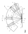
- the training of the measuring arrangement MA goes out of the Figures 2-4 out. It comprises a fixed in the housing G fixed arc body 10, in which all optical or photoelectric components of the measuring device MA are arranged in continuous chambers.
- these components consist of three light sources 11, 12 and 13, for example in the form of LEDs, and a light converter in the form of a color camera 14, each with associated lens systems 21, 22, 23 and 24.
- the arc body 10 has four chambers 31 -34 on.
- the light sources 11, 12 and 13 together with their associated Lens systems 21, 22 and 23, a lighting arrangement for the illumination of a measuring spot MF in three directions of illumination.
- the light converter 14 together with the lens system 24 assigned to it form a pick-up arrangement for light reflected back from the measuring spot MF in an observation direction.
- the optical axes of the emanating from the light sources 11, 12 and 13 and leading to the light transducer 14 beam paths are designated 41, 42, 43 and 44.
- the optical axes 41, 42 and 43 each define a nominal illumination direction
- the optical axis 44 defines a nominal viewing direction.
- the entire measuring arrangement MA is made such that the optical axes 41, 42, 43 and 44 or the illumination directions and the observation direction are located in a common plane, which is referred to below as the illumination observation plane 40 ( Fig. 5 ) and perpendicular to the base plate 7 and the measuring opening 6 located therein.
- the illumination and Aufpickstrahlen réelle are rectilinear.
- the light sources 11, 12 and 13 are controlled by the computer-based control arrangement ST ( Fig. 6 ).
- the latter also controls the light converter or the camera 14 and processes its measuring signals.
- the control arrangement ST displays measurement results on the display device 4 and receives operating commands from the control elements 8.
- the measuring arrangement MA can also be configured vice versa with respect to lighting and observation devices. This means, in the specific case, that the illumination of the measurement object would take place only under a defined illumination direction and for picking up the reflected measurement light under three different observation directions. Of course, any combination of one or more directions of illumination and one or more directions of observation possible.
- Fig. 2 is still a device standards GN registered. It is a (imaginary) straight line that passes through the center of the measuring aperture 6 and the intersection of the optical axes 41,42,43 and 44 and is perpendicular to the plane of the measuring port 6 and the base plate 7 containing them , In the case of a measuring object O with a planar surface MO, the device standard GN coincides with an (normal) surface normal ON (standing at the center of the measuring spot MF and perpendicular to the surface O). Fig. 4 ) together.
- the present invention is not concerned with the actual measurement technology and the evaluation of the measurement results, but with the problem of the positioning of the measuring device on curved surfaces. The following will be discussed in more detail.
- the measuring device is equipped on its housing bottom 5 with a support device designed as a multipoint support.
- the support device in the embodiment shown consists of three pin-shaped support members 51, 52 and 53 which are fixed in the base plate 7 and perpendicular to this protrude from her.
- the three pin-shaped support members 51, 52, and 53 each have a bearing surface 51 a, 52 a and 53 a on ( Figures 2 . 5 and 8th ).
- the lengths of the protruding from the base plate 7 portions of the three support members 51, 52, and 53 are all the same and be a few mm.
- the support surfaces 51a, 52a and 53a of the three support members 51, 52, and 53 lie in a common plane which is parallel to the base plate 7 and the measuring opening 6 located therein and perpendicular to the illumination observation plane 40 and hereinafter as the base plane 50 is designated ( Fig. 5 ).
- the sizes or areas of the Support surfaces 51a, 52a and 53a of the three support members 51, 52, and 53 is less than 20 mm 2 , preferably less than 10 mm 2 , in particular less than 5 mm 2 .
- two pin-shaped support members 51 and 52 are arranged so that the centers of their support surfaces 51 a and 52 a lie on a base line 55 which lies in the base plane 50 and parallel at a small distance a to the illumination observation plane 40 runs ( Fig. 5 ).
- the third support member 53 or its support surface 53a is located at a greater distance b from the illumination observation plane 40 than the distance a of the first and second support members.
- the distance a from the baseline 55 from the illumination observation plane is According to the invention, equal to 0, ie the base line 55 coincides with the illumination observation plane 40.
- the two support members 51 and 52 located on the base line 55 are preferably arranged symmetrically to both sides of the measuring opening 6 and the measuring spot MF, their mutual distance is for example about 10-40 mm.
- the distance b of the third support member 53 from the illumination observation plane 40 is, for example, about 15-40 mm.
- the baseline coincides with the illumination observation plane.
- the measuring device is designed with regard to arrangement and weight distribution of its components such that its center of gravity 50 relating to the device center point S lies between the pin-shaped supporting members 51, 52 and 53.
- the pin-shaped supporting members 51, 52 and 53 are equipped with sensors 51b, 52b and 53b which cooperate with the controller ST and enable the correct positioning of the measuring device on the surface O of the measuring object MO ( Fig. 6 and Fig. 7 ).
- Correct positioning means that all support members 51, 52 and 53 stand up on the surface of the measurement object.
- the sensors 51b, 52b and 53b may, for example, as printing or. Force sensors, in particular be designed as a pressure switch.
- the controller ST can be designed so that it displays, for example via the display device 4 or separate signal lights to the user when the meter is correctly positioned and / or not positioned correctly.
- the design of the support device as a three-point support a secure positioning of the measuring device is achieved both on flat and on curved surfaces of DUTs.
- the inventive arrangement of two pin-shaped supporting organs in said baseline in the illumination observation plane ensures that the illumination and observation directions relative to the measurement spot MF and to the surface normal ON on the measuring spot MF at least in the angle-sensitive illumination observation plane 40 as far as possible remain independent of the surface curvature of the DUT. In this way, due to the surface curvature of the test object conditional Messwertverfabschept be largely avoided.
- the Fig. 8 shows a measuring device, which is placed on a flat or to a plane perpendicular to the illumination observation plane 40 axis cylindrically curved measuring object MO.
- the measuring arrangement MA and the bottom plate 7 are shown by the measuring device. It can be seen that the surface normal ON coincides with the center of the measurement spot with the illumination observation plane 40.
- the Fig. 9 shows an analog representation of the meter, but the measuring object MO (additionally) curved across the illumination observation plane 40 is curved.
- the normal ON is tilted out of the illumination observation plane 40 by a tilt angle ⁇ .
- this relatively small tilt angle has no substantial effect on the measurement result and is in any case less critical than a tilt within the illumination observation plane 40.
- the advantages of the three-point support according to the invention come into play particularly in the case of asymmetrically or irregularly curved surfaces of the measurement object.
- the inventive arrangement of two pin-shaped supporting organs in said baseline in the illumination observation plane ensures that the illumination and observation directions relative to the measurement spot or normal to the measurement spot in the illumination observation plane largely independent of the surface curvature of the measurement object stay. Due to the specific arrangement of the support members according to the invention, possible angular errors all lie in the insensitive direction transversely to the illumination-observation plane, in the critical illumination-observation plane practically no angle errors arise.
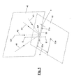
- the Figures 10 and 11 illustrate the practical use of the inventive colorimeter on a measuring object O with two-dimensional curved surface O.
- the two dash-dotted, mutually orthogonal lines T1 and T2 indicate a tangential plane to the surface O in the middle of the measuring spot MF, the dot-dash line GN is the already mentioned above, extending through the center of the measuring port device standards.
- the two angles ⁇ and ⁇ between the device standard GN and the line T1 on the one hand and the line T2 on the other hand illustrate the spatial position of the measuring device MA relative to the surface O of the measuring object O.
- the angle ⁇ is a measure of the tilting of the measuring device MA in the (not the illumination observation plane, the angle ⁇ is a measure of the tilt of the measuring arrangement MA from the illumination observation plane out, where 90.0 ° each means the ideal state without tilting means.
- the three-point support of the measuring device is embodied such that the two support members 51 and 52 are located at a relatively large distance from the illumination-observation plane (not shown) of the measuring arrangement MA.
- angle ⁇ 88.3 °
Landscapes
- Physics & Mathematics (AREA)
- Spectroscopy & Molecular Physics (AREA)
- General Physics & Mathematics (AREA)
- Health & Medical Sciences (AREA)
- Life Sciences & Earth Sciences (AREA)
- Chemical & Material Sciences (AREA)
- Analytical Chemistry (AREA)
- Biochemistry (AREA)
- General Health & Medical Sciences (AREA)
- Immunology (AREA)
- Pathology (AREA)
- Spectrometry And Color Measurement (AREA)
Description
- Die Erfindung betrifft ein Handfarbmessgerät gemäss dem Oberbegriff des unabhängigen Anspruchs 1.
- Handfarbmessgeräte der zur Rede stehenden Art können unabhängig von der zugrundeliegenden Messtechnologie als autonome Geräte oder als Messperipherie zum Einsatz in Verbindung mit einem steuernden und Messdaten auswertenden Rechner ausgebildet sein. Autonome Farbmessgeräte enthalten alle für den Messbetrieb erforderlichen Bedienungs- und Anzeigeorgane sowie eine eigene Stromversorgung und sind darüber hinaus vielfach auch noch mit einer Schnittstelle zur Kommunikation mit einem Rechner ausgestattet, wobei mit dem Rechner sowohl Messdaten als auch Steuerungsdaten ausgetauscht werden können. Als Messperipherie ausgelegte Farbmessgeräte haben in der Regel keine eigenen Bedienungs- und Anzeigeorgane und werden - wie jedes andere Rechnerperipheriegerät - vom übergeordneten Rechner gesteuert. Zur Kommunikation mit einem Rechner sind modernere Farbmessgeräte oft z.B. mit einer sog. USB-Schnittstelle (Universal Serial Bus) ausgerüstet, über welche in vielen Fällen gleichzeitig auch die Stromversorgung (vom angeschlossenen Rechner aus) erfolgen kann.
- Metallicfarben und Lacke mit Effektpigmenten kommen heutzutage immer mehr zum Einsatz nicht nur in der Automobilindustrie. Solche Farben zeigen eine starke Winkelabhängigkeit. Lacke mit Aluminiumflakes zeigen zum Beispiel einen starken Helligkeitsflop. Lacke mit Interferenz-Effekt-Pigmente zeigen dazu auch Farbunterschiede mit geänderter Beobachtungs- oder Beleuchtungsrichtung. Zum Messen solcher Lacke haben sich Mehrwinkelmessgeräte etabliert. Glanzmessung ist ein verwandtes Thema, bei dem das Messresultat ebenfalls winkelsensitiv ist.
- Messgeräte, die solche Eigenschaften erfassen können, müssen dazu ausgebildet sein, das Messobjekt unter einer oder mehreren verschiedenen, genau definierten Beleuchtungsrichtungen (bezogen auf die Normale auf das Messobjekt im Messfleck) zu beleuchten und das vom Messobjekt zurückgestrahlte Licht aus zumindest einer genau definierten Beobachtungsrichtung (ebenfalls bezogen auf die Normale auf das Messobjekt im Messfleck) aufzupicken. Beobachtungsrichtung und Beleuchtungsrichtung können ausgetauscht werden. Gebräuchlich ist in der Praxis eine Messanordnung mit mindestens einer Beleuchtungsrichtung und mehreren Beobachtungsrichtungen.
- Ein typisches Einsatzgebiet für derartige Farbmessgeräte ist die Automobilindustrie, wo es darum geht, Lacke auf Karosserieteilen unter mehreren Winkeln farblich und eventuell in zusätzlichen Appearance-Aspekten auszumessen.
- Eine grosse Schwierigkeit bei diesem Einsatzfall besteht darin, dass oft an gekrümmten Oberflächen gemessen werden muss. Wenn das Messgerät nicht genau und reproduzierbar auf der gekrümmten Messoberfläche aufgesetzt wird, ergeben sich Abweichungen zu den üblicherweise sehr eng tolerierten Beleuchtungs- und Beobachtungsrichtungen, was wiederum zu Messwertverfälschungen führt.
- Es sind schon Handfarbmessgeräte bekannt, die mit speziellen Auflagevorrichtungen zum Aufsetzen der Geräte auf gekrümmten Messobjekten ausgestattet sind. Ein bekanntes Handfarbmessgerät besitzt eine Auflagevorrichtung in Form eines die Messöffnung umgebenden Ringkragens. Diese Auflagevorrichtung ist jedoch nur für regelmässig gekrümmte Oberflächen geeignet. Andere Handfarbmessgeräte sind mit Sensoren ausgestattet, die dem Benutzer anzeigen, wie er das Handfarbmessgerät positionieren muss. Diese Auflagevorrichtung ist einerseits verhältnismässig aufwändig und erfordert anderseits ein aktives Zutun des Benutzers.
- Durch die vorliegende Erfindung soll nun ein Handfarbmessgerät der gattungsgemässen Art dahingehend verbessert werden, dass es mit einfachsten Mitteln sicher und reproduzierbar auch auf gekrümmte Messobjekte aufgesetzt werden kann, so dass die vorgegebenen Beleuchtungs- und Beobachtungsrichtungen genau eingehalten und dadurch Messwertverfälschungen vermieden werden.
- Diese der Erfindung zugrundeliegende Aufgabe wird durch das durch die Merkmale des unabhängigen Anspruchs 1 gekennzeichnete erfindungsgemässe Handfarbmessgerät gelöst. Vorteilhafte Ausgestaltungen und Weiterbildungen des erfindungsgemässen Handfarbmessgeräts sind Gegenstand der abhängigen Ansprüche.
- Das Wesen der Erfindung besteht in Folgendem: Ein Handfarbmessgerät weist ein eine Messanordnung und eine elektronische Steuerung aufnehmendes Gehäuse mit einem Gehäuseboden und einer Messöffnung auf, durch welche hindurch die Beleuchtung eines Messflecks auf einer Oberfläche eines Messobjekts und das Aufpicken des vom Messfleck zurückgestrahlten Messlichts erfolgt. Die Messanordnung umfasst eine Beleuchtungsanordnung zur Beaufschlagung des Messflecks mit Beleuchtungslicht in mindestens einer Beleuchtungsrichtung und eine Aufpickanordnung zur Erfassung des Messlichts in mindestens einer Beobachtungsrichtung. Die mindestens eine Beleuchtungsrichtung und die mindestens eine Beobachtungsrichtung liegen in einer gemeinsamen Beleuchtungs-Beobachtungs-Ebene. Das Gehäuse weist an seinem Gehäuseboden eine Auflagevorrichtung zum Positionieren des Geräts auf der auszumessenden Oberfläche auf. Die Auflagevorrichtung ist als Dreipunktauflage mit drei im Wesentlichen stiftförmigen Stützorganen mit je einer Auflagefläche ausgebildet, wobei die Auflageflächen eines ersten und eines zweiten Stützorgans in einer Basislinie liegen, welche in der Beleuchtungs-Beobachtungs-Ebene liegt, wobei die Auflagefläche, des dritten Stützorganes in einem Abstand zur Beleuchtungs-Beobachtungs-Ebene angeordnet ist und wobei die Auflageflächen der Stützorgane im Wesentlichen in einer zur Beleuchtungs-Beobachtungs-Ebene senkrechten Basisebene liegen.
- Dabei liegt eine Projektion des auf die Basisebene bezogenen Schwerpunkts des Handfarbmessgeräts in Richtung senkrecht auf die Basisebene zwischen den Auflageflächen der Stützorgane. Weiter liegt die Projektion des Schwerpunkts innerhalb eines durch die drei Auflageflächen der drei Stützorgane definierten Dreiecks, wodurch ein stabiler Stand des Handfarbmessgeräts erreicht ist.
- Durch die Ausbildung der Auflagevorrichtung als Dreipunktauflage wird eine sichere Positionierung des Messgeräts sowohl auf ebenen als auch auch gekrümmten Oberflächen von Messobjekten erreicht.
- Das Handfarbmessgerät reagiert in der Beleuchtungs-Beobachtungs-Ebene sehr empfindlich auf Fehlpositionierung mit Winkelfehlern, quer dazu aber deutlich weniger. Durch die erfindungsgemässe Anordnung von zwei stiftförmigen Stützorganen in der genannten Basislinie in der Beleuchtungs-Beobachtungs-Ebene wird gewährleistet, dass die Beleuchtungs- und Beobachtungsrichtungen relativ zum Messfleck bzw. zur Normalen auf den Messfleck zumindest in der Beleuchtungs-Beobachtungsebene weitestgehend unabhängig von der Oberflächenkrümmung des Messobjekts bleiben. Auf diese Weise werden durch die Oberflächenkrümmung des Messobjekts bedingte Messwertverfälschungen weitestgehend vermieden. Durch die erfindungsgemässe spezifische Anordnung der Stützorgane kommen eventuelle Winkelfehler alle in die unempfindliche Richtung quer zur Beleuchtungs-Beobachtungs-Ebene zu liegen, in der kritischen Beleuchtungs-Beobachtungs-Ebene entstehen praktisch keine Winkelfehler.
- Gemäss einer besonders vorteilhaften Ausführungsform sind das erste und das zweite Stützorgan zu beiden Seiten der Messöffnung und im Wesentlichen symmetrisch zu dieser angeordnet. Dies trägt weiter zur Vermeidung von Messwertverfälschungen bei.
- Vorzugsweise sind die Auflageflächen der Stützorgane jeweils kleiner 20 mm2, vorzugsweise kleiner 10 mm2, insbesondere kleiner 5 mm2
- Gemäss der Erfindung ist die Auflagevorrichtung als Dreipunktauflage mit drei im Wesentlichen stiftförmigen Stützorganen ausgebildet. Dies verleiht eine optimale Standfestigkeit des Handfarbmessgeräts.
- Gemäss der Erfindung liegt eine Projektion des auf die Basisebene bezogenen Schwerpunkts des Geräts in Richtung senkrecht auf die Basisebene zwischen den Auflageflächen der Stützorgane. Durch diese Anordnung des Geräteschwerpunkts wird ein stabiler Stand des Messgeräts erreicht und die Gefahr, dass das Gerät kippt, verringert.
- Vorteilhafterweise sind die stiftförmigen Stützorgane mit Sensoren, insbesondere Drucksensoren bzw. Kraftsensoren ausgestattet, welche mit der Steuerung derart zusammenarbeiten, dass überwacht und signalisiert wird, ob alle Stützorgane korrekt auf der Oberfläche des Messobjekts aufsitzen. Dadurch wird verhindert, dass bei unabsichtlichem Verkippen des Messgerätes Messfehler entstehen können.
- Im Folgenden wird die Erfindung anhand der Zeichnung näher erläutert. Es zeigen:
- Fig. 1
- eine Schrägansicht eines Ausführungsbeispiels des erfindungsgemässen Handfarbmessgeräts,
- Fig. 2
- einen Vertikalschnitt durch das Handfarbmessgerät der
Fig. 1 , - Fig. 3
- eine Schrägansicht der Messanordnung des Handfarbmessgeräts,
- Fig. 4
- einen Vertikalschnitt durch die Messanordnung der
Fig. 3 , - Fig. 5
- eine Skizze zur Verdeutlichung der gegenseitigen Lagen von Messanordnung und Stützorganen des Handfarbmessgeräts,
- Fig. 6
- ein Blockschema der optischen und elektronischen Komponenten des Handfarbmessgeräts,
- Fig. 7
- eine Ausbildungsvariante der Stützorgane des erfindungsgemässen Handfarbmessgeräts und
- Fig. 8-11
- vier Skizzen zur Illustration des praktischen Einsatzes des Handfarbmessgeräts.
- Für die nachfolgende Figurenbeschreibung gilt folgende Festlegung: Sind in einer Figur einzelne Bezugszeichen nicht eingetragen, so wird diesbezüglich auf die übrigen Figuren und die dazu gehörigen Beschreibungsteile verwiesen. Unter den verkürzten Begriffen "Farbmessgerät" und "Messgerät" wird immer ein Handfarbmessgerät verstanden. Unter "Messanordnung" wird die Gesamtheit derjenigen Komponenten des Handfarbmessgeräts verstanden, welche zur Beleuchtung eines Messflecks auf der Oberfläche eines Messobjekts und zur Erfassung des von diesem Messfleck zurückgestrahlten Lichts und zur Umwandlung desselben in korrespondierende elektrische Signale dienen.
- Das in
Fig. 1 dargestellte Handfarbmessgerät ist als Ganzes mit HFMG bezeichnet. Es umfasst ein Gehäuse G, das eine Messanordnung MA und eine diese steuernde elektronische Steueranordnung ST aufnimmt (Fig. 6 ). Am Gehäuse G sind seitlich zwei Griffteile 1 und 2 ausgebildet. An der Oberseite des Gehäuses G ist eine Tragschlaufe 3 angeordnet. An der Vorderseite des Gehäuses G ist eine Anzeigeanordnung 4 vorgesehen. Ferner sind an der Oberseite des Gehäuses G inFig. 6 schematisch dargestellte Bedienungsorgane 8 angeordnet. - An der Unterseite weist das Gehäuse G einen Gehäuseboden 5 auf, der durch eine mit einer Messöffnung 6 versehene Basisplatte 7 verstärkt ist. Der Gehäuseboden 5 weist im Bereich der Messöffnung 6 eine Durchbrechung 7a (
Fig. 2 ) auf, so dass Licht aus dem Gehäuseinneren durch die Durchbrechung 7a und die Messöffnung 6 austreten und umgekehrt Licht von aussen durch die Messöffnung 6 und die Durchbrechung 7a in das Gehäuseinnere eintreten kann. - Die Ausbildung der Messanordnung MA geht aus den
Figuren 2-4 hervor. Sie umfasst einen ortfest im Gehäuse G befestigten Bogenkörper 10, in dem alle optischen bzw. photoelektrischen Komponenten der Messanordnung MA in durchgehenden Kammern angeordnet sind. Im gezeigten Ausführungsbeispiel bestehen diese Komponenten aus drei Lichtquellen 11, 12 und 13, z.B. in Form von LEDs, und einem Lichtwandler in Form einer farbtauglichen Kamera 14 mit jeweils zugeordneten Linsensystemen 21, 22, 23 und 24. Entsprechend weist der Bogenkörper 10 vier Kammern 31-34 auf. Die Lichtquellen 11, 12 und 13 bilden zusammen mit den ihnen zugeordneten Linsensystemen 21, 22 und 23 eine Beleuchtungsanordnung für die Beleuchtung eines Messflecks MF in drei Beleuchtungsrichtungen. Entsprechend bildet der Lichtwandler 14 zusammen mit dem ihm zugeordneten Linsensystem 24 eine Aufpickanordnung für vom Messfleck MF in einer Beobachtungsrichtung zurückgestrahltes Licht. - Die optischen Achsen der von den Lichtquellen 11, 12 und 13 ausgehenden und zum Lichtwandler 14 führenden Strahlengänge sind mit 41, 42, 43 und 44 bezeichnet. Die optischen Achsen 41, 42 und 43 definieren je eine nominelle Beleuchtungsrichtung, die optische Achse 44 definiert eine nominelle Beobachtungsrichtung. Die gesamte Messanordnung MA ist so getroffen, dass sich die optischen Achsen 41, 42, 43 und 44 bzw. die Beleuchtungsrichtungen und die Beobachtungsrichtung in einer gemeinsamen Ebene befinden, die im Folgenden als Beleuchtungs-Beobachtungs-Ebene 40 bezeichnet ist (
Fig. 5 ) und senkrecht auf die Basisplatte 7 bzw. die darin befindliche Messöffnung 6 steht. Im gezeigten Ausführungsbeispiel sind die Beleuchtungs- und Aufpickstrahlengänge geradlinig ausgebildet. Es ist jedoch auch möglich, z.B. aus Platzgründen, einen oder mehrere der Strahlengänge abzuknicken, also z.B. mittels Spiegel umzulenken. Wesentlich ist lediglich, dass die optischen Achsen der Strahlengangabschnitte, welche unmittelbar zum Messfleck hin bzw. von diesem weg führen, in einer gemeinsamen Beleuchtungs-Beobachtungsebene liegen. - Die Lichtquellen 11, 12 und 13 werden von der rechnerbasierten Steueranordnung ST gesteuert (
Fig. 6 ). Letztere steuert auch den Lichtwandler bzw. die Kamera 14 an und verarbeitet dessen Messsignale. Die Steueranordnung ST zeigt Messergebnisse auf der Anzeigeanordnung 4 an und nimmt Bedienungsbefehle von den Bedienungsorganen 8 entgegen. - Die Messanordnung MA kann bezüglich Beleuchtungs- und Beobachtungseinrichtungen auch umgekehrt ausgebildet sein. Das heisst im konkreten Fall, dass die Beleuchtung des Messobjekts nur unter einer definierten Beleuchtungsrichtung und dafür das Aufpicken des zurückgestrahlten Messlichts unter drei verschiedenen Beobachtungsrichtungen erfolgen würden. Selbstverständlich sind auch beliebige Kombinationen von einer oder mehreren Beleuchtungsrichtungen und einer oder mehreren Beobachtungsrichtungen möglich.
- In
Fig. 2 ist noch eine Gerätenormale GN eingetragen. Es handelt sich dabei um eine (gedachte) gerade Linie, die durch den Mittelpunkt der Messöffnung 6 bzw. den Schnittpunkt der optischen Achsen 41,42,43 und 44 verläuft und senkrecht auf die Ebene der Messöffnung 6 bzw. der diese enthaltenden Basisplatte 7 steht. Bei einem Messobjekt O mit ebener Oberfläche MO fällt die Gerätenormale GN mit einer durch den Mittelpunkt des Messflecks MF und senkrecht auf die Oberfläche O stehenden (gedachten) Oberflächennormalen ON (Fig. 4 ) zusammen. - Soweit entspricht das beschriebene Farbmessgerät im Grundsatz herkömmlichen Farbmessgeräten dieser Art, so dass der Fachmann diesbezüglich keiner weiteren Erläuterung bedarf.
- Die vorliegende Erfindung befasst sich nicht mit der eigentlichen Messtechnologie und der Auswertung der Messergebnisse, sondern mit der Problematik der Positionierung des Messgeräts auf gekrümmten Oberflächen. Im Folgenden wird darauf näher eingegangen.
- Gemäss einem ersten wichtigen Aspekt der Erfindung ist das Messgerät an seinem Gehäuseboden 5 mit einer als Mehrpunktauflage ausgebildeten Auflagevorrichtung ausgestattet. Konkret besteht die Auflagevorrichtung im gezeigten Ausführungsbeispiel aus drei stiftförmigen Stützorganen 51, 52 und 53, die in der Basisplatte 7 befestigt sind und senkrecht zu dieser aus ihr herausragen. Die drei stiftförmigen Stützorgane 51, 52, und 53 weisen je eine Auflagefläche 51a, 52a und 53 a auf (
Figuren 2 ,5 und8 ). Die Längen der aus der Basisplatte 7 herausragenden Abschnitte der drei Stützorgane 51, 52, und 53 sind alle gleich und betragen einige wenige mm. Die Auflageflächen 51a, 52a und 53a der drei Stützorgane 51, 52, und 53 liegen in einer gemeinsamen Ebene, die parallel zur Basisplatte 7 bzw. der in dieser befindlichen Messöffnung 6 und senkrecht zur Beleuchtungs-Beobachtungs-Ebene 40 verläuft und im Folgenden als Basisebene 50 bezeichnet ist (Fig. 5 ). Die Grössen bzw. Flächen der Auflageflächen 51a, 52a und 53a der drei Stützorgane 51, 52, und 53 ist kleiner 20 mm2, vorzugsweise kleiner 10 mm2, insbesondere kleiner 5 mm2. - Gemäss einem weiteren wichtigen Gedanken der Erfindung sind zwei stiftförmige Stützorgane 51 und 52 so angeordnet, dass die Mittelpunkte ihrer Auflageflächen 51 a und 52a auf einer Basislinie 55 liegen, welche in der Basisebene 50 liegt und parallel in geringem Abstand a zur Beleuchtungs-Beobachtungs-Ebene 40 verläuft (
Fig. 5 ). Das dritte Stützorgan 53 bzw. dessen Auflagefläche 53a befindet sich in einem gegenüber dem Abstand a des ersten bzw. des zweiten Stützorgans grösseren Abstand b von der Beleuchtungs-Beobachtungs-Ebene 40. Der Abstand a der Basislinie 55 von der Beleuchtungs-Beobachtungs-Ebene ist erfindungsgemäß gleich 0, d.h. die Basislinie 55 fällt mit der Beleuchtungs-Beobachtungs-Ebene 40 zusammen. Die beiden auf der Basislinie 55 befindlichen Stützorgane 51 und 52 sind vorzugsweise symmetrisch zu beiden Seiten der Messöffnung 6 bzw. des Messflecks MF angeordnet, ihr gegenseitiger Abstand beträgt beispielsweise etwa 10-40 mm. Der Abstand b des dritten Stützorgans 53 von der Beleuchtungs-Beobachtungs-Ebene 40 beträgt beispielsweise etwa 15-40 mm. - In
Fig. 5 befinden sich die drei Stützorgane 51, 52 und 53 alle auf der selben Seite der Beleuchtungs-Beobachtungs-Ebene 40. Selbstverständlich können das erste und das zweite Stützorgan 51 und 52 einerseits und das dritte Stützorgan 53 (und eventuelle weitere Stützorgane) anderseits auch auf verschiedenen Seiten der Beleuchtungs-Beobachtungs-Ebene 40 liegen, so wie dies bei den Ausführungsbeispielen derFiguren 10 und11 dargestellt ist. Erfindungsgemäß fällt jedoch die Basislinie mit der Beleuchtungs-Beobachtungs-Ebene zusammen. Gemäss einem weiteren wichtigen Erfindungsgedanken ist das Messgerät bezüglich Anordnung und Gewichtsverteilung seiner Komponenten so konzipiert, dass sein auf die Basisebene 50 bezogener Geräteschwerpunkt S zwischen den stiftförmigen Stützorganen 51, 52 und 53 liegt. In anderen Worten liegt dann eine Projektion S' des Geräteschwerpunkts S in Richtung senkrecht zur Basisebene 50 innerhalb eines durch die drei Auflageflächen 51a, 52a und 53a der drei Stützorgane 51, 52 und 53 definierten Dreiecks (Fig. 5 ). Durch diese Anordnung des Geräteschwerpunkts S wird ein stabiler Stand des Messgeräts erreicht und die Gefahr, dass das Gerät kippt, verringert. - Gemäss einer besonders zweckmässigen Ausbildung des erfindungsgemässen Messgeräts sind die stiftförmigen Stützorgane 51, 52 und 53 mit Sensoren 51b, 52b und 53b ausgestattet, welche mit der Steuerung ST zusammenarbeiten und die korrekte Positionierung des Messgeräts auf der Oberfläche O des Messobjekts MO zu überwachen ermöglichen (
Fig. 6 und Fig. 7 ). Unter korrekter Positionierung ist zu verstehen, dass alle Stützorgane 51, 52 und 53 auf der Oberfläche des Messobjekts aufstehen. Die Sensoren 51b, 52b und 53b können beispielsweise als Druck-bzw. Kraftsensoren, insbesondere als Druckschalter ausgebildet sein. Die Steuerung ST kann so ausgelegt sein, dass sie z.B. über die Anzeigeanordnung 4 oder separate Signalleuchten dem Benutzer anzeigt, wenn das Messgerät korrekt positioniert und/oder nicht korrekt positioniert ist. - Durch die Ausbildung der Auflagevorrichtung als Dreipunktauflage wird eine sichere Positionierung des Messgeräts sowohl auf ebenen als auch auf gekrümmten Oberflächen von Messobjekten erreicht. Durch die erfindungsgemässe Anordnung von zwei stiftförmigen Stützorganen in der genannten Basislinie in der Beleuchtungs-Beobachtungs-Ebene wird gewährleistet, dass die Beleuchtungs- und Beobachtungsrichtungen relativ zum Messfleck MF bzw. zur Oberflächennormalen ON auf den Messfleck MF zumindest in der winkelempfindlichen Beleuchtungs-Beobachtungsebene 40 weitestgehend unabhängig von der Oberflächenkrümmung des Messobjekts bleiben. Auf diese Weise werden durch die Oberflächenkrümmung des Messobjekts bedingte Messwertverfälschungen weitestgehend vermieden.
- Die
Fig. 8 zeigt ein Messgerät, das auf ein ebenes bzw. um eine zur Beleuchtungs-Beobachtungs-Ebene 40 senkrechte Achse zylindrisch gekrümmtes Messobjekt MO aufgesetzt ist. Vom Messgerät sind der Übersichtlichkeit halber nur die Messanordnung MA und die Bodenplatte 7 dargestellt. Man erkennt, dass die Oberflächennormale ON auf die Mitte des Messflecks mit der Beleuchtungs-Beobachtungs-Ebene 40 zusammenfällt. - Die
Fig. 9 zeigt eine analoge Darstellung des Messgeräts, wobei aber das Messobjekt MO (zusätzlich) quer Beleuchtungs-Beobachtungs-Ebene 40 gekrümmt ist. In diesem Fall ist die Normale ON um einen Kippwinkel α aus der Beleuchtungs-Beobachtungs-Ebene 40 herausgekippt. Dieser relativ kleine Kippwinkel hat aber keinen substantiellen Einfluss auf das Messergebnis und ist auf jeden Fall weniger kritisch als eine Verkippung innerhalb der Beleuchtungs-Beobachtungs-Ebene 40. - Die Vorteile der erfindungsgemässen Dreipunktauflage kommen insbesondere bei unsymmetrisch oder unregelmässig gekrümmten Oberflächen des Messobjekts zum Tragen. Durch die erfindungsgemässe Anordnung von zwei stiftförmigen Stützorganen in der genannten Basislinie in der Beleuchtungs-Beobachtungs-Ebene wird gewährleistet, dass die Beleuchtungs- und Beobachtungsrichtungen relativ zum Messfleck bzw. zur Normalen auf den Messfleck in der Beleuchtungs-Beobachtungsebene weitestgehend unabhängig von der Oberflächenkrümmung des Messobjekts bleiben. Durch die erfindungsgemässe spezifische Anordnung der Stützorgane kommen eventuelle Winkelfehler alle in die unempfindliche Richtung quer zur Beleuchtungs-Beobachtungs-Ebene zu liegen, in der kritischen Beleuchtungs-Beobachtungs-Ebene entstehen praktisch keine Winkelfehler.
- Die
Figuren 10 und11 illustrieren den praktischen Einsatz des erfindungsgemässen Farbmessgeräts an einem Messobjekt O mit zweidimensional gekrümmter Oberfläche O. Vom Messgerät ist der Übersichtlichkeit halber nur die Messanordnung MA zusammen mit der Basisplatte 7 und den darin angeordneten Stützorganen 51, 52 und 53 dargestellt. Die beiden strichpunktierten, zu einander orthogonalen Linien T1 und T2 deuten eine Tangentialebene an die Oberfläche O in der Mitte des Messflecks MF an, die strichpunktierte Linie GN ist die schon weiter vorne erwähnte, durch die Mitte der Messöffnung verlaufende Gerätenormale. Die beiden Winkel βund ω zwischen der Gerätenormalen GN und der Linie T1 einerseits und der Linie T2 anderseits verdeutlichen die räumliche Lage der Messanordnung MA relativ zur Oberfläche O des Messobjekts O. Der Winkel ω ist ein Mass für die Verkippung der Messanordnung MA in der (nicht dargestellten) Beleuchtungs-Beobachtungs-Ebene, der Winkel β ist ein Mass für die Verkippung der Messanordnung MA aus der Beleuchtungs-Beobachtungs-Ebene heraus, wobei 90.0° jeweils den Idealzustand ohne Verkippung bedeutet. - In
Fig. 10 ist die Dreipunktauflage des Messgeräts beispielhaft so ausgebildet, dass sich die beiden Stützorgane 51 und 52 in einem relativ grossen Abstand zur (nicht dargestellten) Beleuchtungs-Beobachtungs-Ebene der Messanordnung MA befinden. Man erkennt hier eine deutliche Verkippung (Abweichung vom Idealzustand 90.0°), wobei aber die Verkippung in der Beleuchtungs-Beobachtungs-Ebene (Winkel ω = 89.17°) immer noch signifikant geringer ist als in Richtung quer dazu (Winkel β = 88.3°). - Beim Ausführungsbeispiel der
Fig. 11 liegen die beiden Stützorgane 51 und 52 in der (nicht dargestellten) Beleuchtungs-Beobachtungs-Ebene der Messanordnung MA. Man erkennt hier, dass die Verkippung der Messanordnung in der Beleuchtungs-Beobachtungs-Ebene (Winkel ω = 89.99°) praktisch verschwindet und die Verkippung in Richtung quer dazu (Winkel β = 89.12°) ebenfalls relativ klein ist.
Claims (8)
- Handfarbmessgerät (HFMG) mit einem eine Messanordnung (MA) und eine elektronische Steuerung (ST) aufnehmenden Gehäuse (G) mit einem Gehäuseboden (5) und einer Messöffnung (6), durch welche hindurch die Beleuchtung eines Messflecks (MF) auf einer Oberfläche (O) eines Messobjekts (MO) und das Aufpicken des vom Messfleck (MF) zurückgestrahlten Messlichts erfolgt, wobei die Messanordnung (MA) eine Beleuchtungsanordnung (11, 12, 13, 21, 22, 23) zur Beaufschlagung des Messflecks (MF) mit Beleuchtungslicht in mindestens einer Beleuchtungsrichtung (41, 42, 43) und eine Aufpickanordnung (14, 24) zur Erfassung des von dem Messfleck (MF) zurückgestrahlten Messlichts in mindestens einer Beobachtungsrichtung (44) umfasst, wobei die mindestens eine Beleuchtungsrichtung (41, 42, 43) und die mindestens eine Beobachtungsrichtung (44) in einer gemeinsamen Beleuchtungs-Beobachtungs-Ebene (40) liegen, wobei das Gehäuse (G) an seinem Gehäuseboden (5) eine Auflagevorrichtung (7, 51, 52, 53) zum Positionieren des Geräts auf der auszumessenden Oberfläche (O) aufweist, wobei die Auflagevorrichtung als Mehrpunktauflage mit Stützorganen (51, 52, 53) mit je einer Auflagefläche (51a, 52a, 53a) ausgebildet ist, und wobei die Auflageflächen (51a, 52a, 53a) der Stützorgane (51, 52, 53) im Wesentlichen in einer zur Beleuchtungs-Beobachtungs-Ebene (40) senkrechten Basisebene (50) liegen,
dadurch gekennzeichnet, dass
die Auflagevorrichtung (7, 51, 52, 53) als Dreipunktauflage mit drei im Wesentlichen stiftförmigen Stützorganen (51, 52, 53) ausgebildet ist;
die Auflageflächen (51a, 52a) eines ersten und eines zweiten Stützorgans (51, 52) in einer Basislinie (55) liegen, welche in der Beleuchtungs-Beobachtungs-Ebene (40) liegt,
die Auflagefläche (53a) des dritten Sfützozgans (53) in einem Abstand (b) zur Beleuchtungs-Beobachtungs-Ebene (40) angeordnet ist;
eine Projektion (S') des auf die Basisebene (50) bezogenen Schwerpunkts (S) des Handfarbmessgeräts (HFMG) in Richtung senkrecht auf die Basisebene (50) zwischen den Auflageflächen (51a, 52a, 53a) der Stützorgane (51, 52, 53) liegt; und
die Projektion (S') des Schwerpunkts (S) innerhalb eines durch die drei Auflageflächen (51a, 52a, 53a) der drei Stützorgane (51, 52, 53) definierten Dreiecks liegt, wodurch ein stabiler Stand des Handfarbmessgeräts (HMFG) erreicht ist. - Handfarbmessgerät (HFMG) nach Anspruch 1, wobei das erste und das zweite Stützorgan (51, 52) zu beiden Seiten der Messöffnung (6) und im Wesentlichen symmetrisch zu dieser angeordnet sind.
- Handfarbmessgerät (HFMG) nach Anspruch 1 oder 2, wobei die Auflageflächen (51a, 52a, 53a) der Stützorgane (51, 52, 53) jeweils kleiner 20 mm2 sind.
- Handfarbmessgerät (HFMG) nach Anspruch 1 oder 2, wobei die Auflageflächen (51a, 52a, 53a) der Stützorgane (51, 52,53) jeweils kleiner 10 mm2 sind.
- Handfarbmessgerät (HFMG) nach Anspruch 1 oder 2, wobei die Anlageflächen (51a, 52a, 53a) der Stützorgane (51, 52, 53) jeweils kleiner 5 mm2 sind.
- Haudfarbmessgerät (HFMG) nach einem der vorangehenden Ansprüche, wobei die stiftförmigen Stützorgane (51, 52, 53) mit Sensoren, insbesondere Drucksensoren (51b, 52b, 53b) ausgestattet sind, welche mit der Steuerung (ST) derart zusammenarbeiten, dass überwacht und signalisiert wird, ob alle Stützorgane (51, 52, 53) korrekt auf der Oberfläche (O) des Messobjekts (MO) aufsitzen.
- Handfarbmessgerät (HFMG) nach Anspruch 2, wobei das erste und zweite Stützorgane (51, 52) einen gegenseitigen Abstand von 10 mm bis 40 mm aufweisen.
- Handfarbmessgerät (HFMG) nach irgendeinem der vorherigen Ansprüche, wobei der Abstand (b) des dritten Stützorgans (53) von der Beleuchtungs-Beobachtungs-Ebene (40) 15 mm bis 40 mm beträgt.
Priority Applications (2)
| Application Number | Priority Date | Filing Date | Title |
|---|---|---|---|
| EP12182902.2A EP2703789B1 (de) | 2012-09-04 | 2012-09-04 | Handfarbmessgerät |
| US14/013,170 US9025155B2 (en) | 2012-09-04 | 2013-08-29 | Hand-held color measurement device |
Applications Claiming Priority (1)
| Application Number | Priority Date | Filing Date | Title |
|---|---|---|---|
| EP12182902.2A EP2703789B1 (de) | 2012-09-04 | 2012-09-04 | Handfarbmessgerät |
Publications (2)
| Publication Number | Publication Date |
|---|---|
| EP2703789A1 EP2703789A1 (de) | 2014-03-05 |
| EP2703789B1 true EP2703789B1 (de) | 2015-02-18 |
Family
ID=47071103
Family Applications (1)
| Application Number | Title | Priority Date | Filing Date |
|---|---|---|---|
| EP12182902.2A Active EP2703789B1 (de) | 2012-09-04 | 2012-09-04 | Handfarbmessgerät |
Country Status (2)
| Country | Link |
|---|---|
| US (1) | US9025155B2 (de) |
| EP (1) | EP2703789B1 (de) |
Families Citing this family (8)
| Publication number | Priority date | Publication date | Assignee | Title |
|---|---|---|---|---|
| EP2975370B1 (de) | 2014-07-14 | 2020-11-04 | X-Rite Switzerland GmbH | Farbmessgerät |
| EP3078950B8 (de) | 2015-04-08 | 2024-06-26 | X-Rite Europe GmbH | Farbmessverfahren und farbmessgerät |
| WO2017217261A1 (ja) * | 2016-06-15 | 2017-12-21 | シャープ株式会社 | 分光測定装置 |
| US11130438B2 (en) | 2019-09-28 | 2021-09-28 | Heath Miller | Propane tank tie down system and method of use |
| USD949032S1 (en) * | 2019-11-27 | 2022-04-19 | Byk-Gardner Gmbh | Color appearance measurement instrument |
| USD949713S1 (en) * | 2019-11-27 | 2022-04-26 | Byk-Gardner Gmbh | Appearance measurement instrument |
| CN112345471B (zh) * | 2020-11-10 | 2025-04-29 | 深圳拓匠印前科技有限公司 | 手持式智能测色仪 |
| USD1093185S1 (en) * | 2024-01-15 | 2025-09-16 | Byk-Gardner Gmbh | Spectral photometer |
Family Cites Families (6)
| Publication number | Priority date | Publication date | Assignee | Title |
|---|---|---|---|---|
| JP2982472B2 (ja) * | 1992-03-11 | 1999-11-22 | 日産自動車株式会社 | 塗装面性状測定装置 |
| DE19633557A1 (de) * | 1996-08-21 | 1998-03-05 | Techkon Elektronik Gmbh | Spektrales Handmeßgerät |
| DE10018982B4 (de) * | 2000-04-17 | 2016-08-11 | Byk-Gardner Gmbh | Vorrichtung und Verfahren zum Messen von Transmissions- und Reflexionseigenschaften von Gegenständen und Oberflächen |
| DE102004034167A1 (de) * | 2004-07-15 | 2006-02-09 | Byk Gardner Gmbh | Vorrichtung zur goniometrischen Untersuchung optischer Oberflächeneigenschaften |
| EP1655589B1 (de) * | 2004-11-03 | 2008-04-09 | GretagMacbeth, LLC | Goniometrisches Spektrophotometer mit zweifachem Beleuchtungswinkel |
| JP5256772B2 (ja) | 2008-02-25 | 2013-08-07 | パナソニック株式会社 | モータおよびそれを用いた電子機器 |
-
2012
- 2012-09-04 EP EP12182902.2A patent/EP2703789B1/de active Active
-
2013
- 2013-08-29 US US14/013,170 patent/US9025155B2/en active Active
Also Published As
| Publication number | Publication date |
|---|---|
| US9025155B2 (en) | 2015-05-05 |
| US20140063500A1 (en) | 2014-03-06 |
| EP2703789A1 (de) | 2014-03-05 |
Similar Documents
| Publication | Publication Date | Title |
|---|---|---|
| EP2703789A1 (de) | Handfarbmessgerät | |
| EP2270450B1 (de) | Handlichtmessgerät | |
| DE3877665T2 (de) | Verfahren und vorrichtung zum kalibrieren eines kontaktlosen messfuehlers mit bezug auf einem externen koordinatensystem. | |
| EP1342050A1 (de) | Ermittlung von korrekturparametern einer dreh- schwenkeinheit mit messendem sensor ( koordinatenmessgerät ) über zwei parameterfelder | |
| DE10122313A1 (de) | Verfahren und Vorrichtung zur berührungsfreien Untersuchung eines Gegenstandes, insbesondere hinsichtlich dessen Oberflächengestalt | |
| EP1845350A1 (de) | Handfarbmessgerät mit zwei relativ zueinander verstellbaren Gehäuseteilen, in denen die passiven Komponenten bzw. die optoelektronische Messeinheit untergebracht sind | |
| DE102014216958B4 (de) | Verschiebungssensor | |
| EP2416132A1 (de) | Waage mit Anzeige- und Bedieneinheit | |
| DE102013207081B4 (de) | Prüfvorrichtung zum gravimetrischen Prüfen von Mehrkanalpipetten | |
| DE10311247B4 (de) | Portable Einrichtung zum Erfassen einer Lage und von Abmessungen eines Objekts | |
| EP2674802A1 (de) | Fernoptisches Gerät mit Steuerelektronik | |
| EP3078950B1 (de) | Farbmessverfahren und farbmessgerät | |
| EP3910314B1 (de) | Verfahren und vorrichtung zur analyse der wechselwirkung zwischen einer oberfläche einer probe und einer flüssigkeit | |
| DE202012008448U1 (de) | Handfarbmessgerät | |
| EP2975370B1 (de) | Farbmessgerät | |
| DE10012273A1 (de) | Anlage zur messtechnischen räumlichen 3D-Lageerfassung von Oberflächenpunkten | |
| EP1890817A1 (de) | Thermocycler | |
| EP2458404A2 (de) | Distanzmessgerät und Vermessungssystem | |
| EP3086151A1 (de) | System und verfahren zum ausrichten einer blende relativ zu einer optischen achse | |
| EP0989398B1 (de) | Vorrichtung zur Messung oder visuellen Abmusterung der Farbe oder von Farbeffekten von Oberflächen | |
| DE102012207226B4 (de) | Vorrichtung zur Analyse eines Druckexemplars | |
| DE102012014263B3 (de) | Vorrichtung zur Kalibrierung eines optischenSensors | |
| DE102006005874C5 (de) | Verfahren zum berührungsfreien Vermessen | |
| DE102004008038B4 (de) | Elektrodenzustandsmeßeinrichtung | |
| DE102008045987A1 (de) | Vorrichtung zur Messung einer Spektralverteilung eines mit einer Druckeinrichtung hergestellten transluzenten Druckerzeugnisses |
Legal Events
| Date | Code | Title | Description |
|---|---|---|---|
| 17P | Request for examination filed |
Effective date: 20130418 |
|
| AK | Designated contracting states |
Kind code of ref document: A1 Designated state(s): AL AT BE BG CH CY CZ DE DK EE ES FI FR GB GR HR HU IE IS IT LI LT LU LV MC MK MT NL NO PL PT RO RS SE SI SK SM TR |
|
| AX | Request for extension of the european patent |
Extension state: BA ME |
|
| PUAI | Public reference made under article 153(3) epc to a published international application that has entered the european phase |
Free format text: ORIGINAL CODE: 0009012 |
|
| GRAP | Despatch of communication of intention to grant a patent |
Free format text: ORIGINAL CODE: EPIDOSNIGR1 |
|
| INTG | Intention to grant announced |
Effective date: 20140723 |
|
| GRAS | Grant fee paid |
Free format text: ORIGINAL CODE: EPIDOSNIGR3 |
|
| RAP1 | Party data changed (applicant data changed or rights of an application transferred) |
Owner name: X-RITE SWITZERLAND GMBH |
|
| GRAA | (expected) grant |
Free format text: ORIGINAL CODE: 0009210 |
|
| AK | Designated contracting states |
Kind code of ref document: B1 Designated state(s): AL AT BE BG CH CY CZ DE DK EE ES FI FR GB GR HR HU IE IS IT LI LT LU LV MC MK MT NL NO PL PT RO RS SE SI SK SM TR |
|
| REG | Reference to a national code |
Ref country code: GB Ref legal event code: FG4D Free format text: NOT ENGLISH |
|
| REG | Reference to a national code |
Ref country code: CH Ref legal event code: EP |
|
| REG | Reference to a national code |
Ref country code: AT Ref legal event code: REF Ref document number: 710842 Country of ref document: AT Kind code of ref document: T Effective date: 20150315 |
|
| REG | Reference to a national code |
Ref country code: IE Ref legal event code: FG4D Free format text: LANGUAGE OF EP DOCUMENT: GERMAN |
|
| REG | Reference to a national code |
Ref country code: DE Ref legal event code: R096 Ref document number: 502012002279 Country of ref document: DE Effective date: 20150402 |
|
| REG | Reference to a national code |
Ref country code: NL Ref legal event code: VDEP Effective date: 20150218 |
|
| REG | Reference to a national code |
Ref country code: LT Ref legal event code: MG4D |
|
| PG25 | Lapsed in a contracting state [announced via postgrant information from national office to epo] |
Ref country code: FI Free format text: LAPSE BECAUSE OF FAILURE TO SUBMIT A TRANSLATION OF THE DESCRIPTION OR TO PAY THE FEE WITHIN THE PRESCRIBED TIME-LIMIT Effective date: 20150218 Ref country code: SE Free format text: LAPSE BECAUSE OF FAILURE TO SUBMIT A TRANSLATION OF THE DESCRIPTION OR TO PAY THE FEE WITHIN THE PRESCRIBED TIME-LIMIT Effective date: 20150218 Ref country code: ES Free format text: LAPSE BECAUSE OF FAILURE TO SUBMIT A TRANSLATION OF THE DESCRIPTION OR TO PAY THE FEE WITHIN THE PRESCRIBED TIME-LIMIT Effective date: 20150218 Ref country code: HR Free format text: LAPSE BECAUSE OF FAILURE TO SUBMIT A TRANSLATION OF THE DESCRIPTION OR TO PAY THE FEE WITHIN THE PRESCRIBED TIME-LIMIT Effective date: 20150218 Ref country code: LT Free format text: LAPSE BECAUSE OF FAILURE TO SUBMIT A TRANSLATION OF THE DESCRIPTION OR TO PAY THE FEE WITHIN THE PRESCRIBED TIME-LIMIT Effective date: 20150218 Ref country code: NO Free format text: LAPSE BECAUSE OF FAILURE TO SUBMIT A TRANSLATION OF THE DESCRIPTION OR TO PAY THE FEE WITHIN THE PRESCRIBED TIME-LIMIT Effective date: 20150518 |
|
| PG25 | Lapsed in a contracting state [announced via postgrant information from national office to epo] |
Ref country code: GR Free format text: LAPSE BECAUSE OF FAILURE TO SUBMIT A TRANSLATION OF THE DESCRIPTION OR TO PAY THE FEE WITHIN THE PRESCRIBED TIME-LIMIT Effective date: 20150519 Ref country code: NL Free format text: LAPSE BECAUSE OF FAILURE TO SUBMIT A TRANSLATION OF THE DESCRIPTION OR TO PAY THE FEE WITHIN THE PRESCRIBED TIME-LIMIT Effective date: 20150218 Ref country code: LV Free format text: LAPSE BECAUSE OF FAILURE TO SUBMIT A TRANSLATION OF THE DESCRIPTION OR TO PAY THE FEE WITHIN THE PRESCRIBED TIME-LIMIT Effective date: 20150218 Ref country code: RS Free format text: LAPSE BECAUSE OF FAILURE TO SUBMIT A TRANSLATION OF THE DESCRIPTION OR TO PAY THE FEE WITHIN THE PRESCRIBED TIME-LIMIT Effective date: 20150218 Ref country code: IS Free format text: LAPSE BECAUSE OF FAILURE TO SUBMIT A TRANSLATION OF THE DESCRIPTION OR TO PAY THE FEE WITHIN THE PRESCRIBED TIME-LIMIT Effective date: 20150618 |
|
| PG25 | Lapsed in a contracting state [announced via postgrant information from national office to epo] |
Ref country code: CZ Free format text: LAPSE BECAUSE OF FAILURE TO SUBMIT A TRANSLATION OF THE DESCRIPTION OR TO PAY THE FEE WITHIN THE PRESCRIBED TIME-LIMIT Effective date: 20150218 Ref country code: DK Free format text: LAPSE BECAUSE OF FAILURE TO SUBMIT A TRANSLATION OF THE DESCRIPTION OR TO PAY THE FEE WITHIN THE PRESCRIBED TIME-LIMIT Effective date: 20150218 Ref country code: RO Free format text: LAPSE BECAUSE OF FAILURE TO SUBMIT A TRANSLATION OF THE DESCRIPTION OR TO PAY THE FEE WITHIN THE PRESCRIBED TIME-LIMIT Effective date: 20150218 Ref country code: EE Free format text: LAPSE BECAUSE OF FAILURE TO SUBMIT A TRANSLATION OF THE DESCRIPTION OR TO PAY THE FEE WITHIN THE PRESCRIBED TIME-LIMIT Effective date: 20150218 Ref country code: SK Free format text: LAPSE BECAUSE OF FAILURE TO SUBMIT A TRANSLATION OF THE DESCRIPTION OR TO PAY THE FEE WITHIN THE PRESCRIBED TIME-LIMIT Effective date: 20150218 |
|
| REG | Reference to a national code |
Ref country code: DE Ref legal event code: R097 Ref document number: 502012002279 Country of ref document: DE |
|
| PG25 | Lapsed in a contracting state [announced via postgrant information from national office to epo] |
Ref country code: PL Free format text: LAPSE BECAUSE OF FAILURE TO SUBMIT A TRANSLATION OF THE DESCRIPTION OR TO PAY THE FEE WITHIN THE PRESCRIBED TIME-LIMIT Effective date: 20150218 |
|
| PLBE | No opposition filed within time limit |
Free format text: ORIGINAL CODE: 0009261 |
|
| STAA | Information on the status of an ep patent application or granted ep patent |
Free format text: STATUS: NO OPPOSITION FILED WITHIN TIME LIMIT |
|
| PG25 | Lapsed in a contracting state [announced via postgrant information from national office to epo] |
Ref country code: IT Free format text: LAPSE BECAUSE OF FAILURE TO SUBMIT A TRANSLATION OF THE DESCRIPTION OR TO PAY THE FEE WITHIN THE PRESCRIBED TIME-LIMIT Effective date: 20150218 |
|
| 26N | No opposition filed |
Effective date: 20151119 |
|
| PG25 | Lapsed in a contracting state [announced via postgrant information from national office to epo] |
Ref country code: SI Free format text: LAPSE BECAUSE OF FAILURE TO SUBMIT A TRANSLATION OF THE DESCRIPTION OR TO PAY THE FEE WITHIN THE PRESCRIBED TIME-LIMIT Effective date: 20150218 |
|
| PG25 | Lapsed in a contracting state [announced via postgrant information from national office to epo] |
Ref country code: MC Free format text: LAPSE BECAUSE OF FAILURE TO SUBMIT A TRANSLATION OF THE DESCRIPTION OR TO PAY THE FEE WITHIN THE PRESCRIBED TIME-LIMIT Effective date: 20150218 Ref country code: LU Free format text: LAPSE BECAUSE OF FAILURE TO SUBMIT A TRANSLATION OF THE DESCRIPTION OR TO PAY THE FEE WITHIN THE PRESCRIBED TIME-LIMIT Effective date: 20150904 |
|
| REG | Reference to a national code |
Ref country code: IE Ref legal event code: MM4A |
|
| REG | Reference to a national code |
Ref country code: FR Ref legal event code: ST Effective date: 20160531 |
|
| PG25 | Lapsed in a contracting state [announced via postgrant information from national office to epo] |
Ref country code: IE Free format text: LAPSE BECAUSE OF NON-PAYMENT OF DUE FEES Effective date: 20150904 |
|
| PG25 | Lapsed in a contracting state [announced via postgrant information from national office to epo] |
Ref country code: FR Free format text: LAPSE BECAUSE OF NON-PAYMENT OF DUE FEES Effective date: 20150930 |
|
| PG25 | Lapsed in a contracting state [announced via postgrant information from national office to epo] |
Ref country code: MT Free format text: LAPSE BECAUSE OF FAILURE TO SUBMIT A TRANSLATION OF THE DESCRIPTION OR TO PAY THE FEE WITHIN THE PRESCRIBED TIME-LIMIT Effective date: 20150218 |
|
| PG25 | Lapsed in a contracting state [announced via postgrant information from national office to epo] |
Ref country code: HU Free format text: LAPSE BECAUSE OF FAILURE TO SUBMIT A TRANSLATION OF THE DESCRIPTION OR TO PAY THE FEE WITHIN THE PRESCRIBED TIME-LIMIT; INVALID AB INITIO Effective date: 20120904 Ref country code: SM Free format text: LAPSE BECAUSE OF FAILURE TO SUBMIT A TRANSLATION OF THE DESCRIPTION OR TO PAY THE FEE WITHIN THE PRESCRIBED TIME-LIMIT Effective date: 20150218 Ref country code: BG Free format text: LAPSE BECAUSE OF FAILURE TO SUBMIT A TRANSLATION OF THE DESCRIPTION OR TO PAY THE FEE WITHIN THE PRESCRIBED TIME-LIMIT Effective date: 20150218 |
|
| PG25 | Lapsed in a contracting state [announced via postgrant information from national office to epo] |
Ref country code: CY Free format text: LAPSE BECAUSE OF FAILURE TO SUBMIT A TRANSLATION OF THE DESCRIPTION OR TO PAY THE FEE WITHIN THE PRESCRIBED TIME-LIMIT Effective date: 20150218 |
|
| PG25 | Lapsed in a contracting state [announced via postgrant information from national office to epo] |
Ref country code: BE Free format text: LAPSE BECAUSE OF NON-PAYMENT OF DUE FEES Effective date: 20150930 |
|
| PG25 | Lapsed in a contracting state [announced via postgrant information from national office to epo] |
Ref country code: PT Free format text: LAPSE BECAUSE OF FAILURE TO SUBMIT A TRANSLATION OF THE DESCRIPTION OR TO PAY THE FEE WITHIN THE PRESCRIBED TIME-LIMIT Effective date: 20150218 Ref country code: TR Free format text: LAPSE BECAUSE OF FAILURE TO SUBMIT A TRANSLATION OF THE DESCRIPTION OR TO PAY THE FEE WITHIN THE PRESCRIBED TIME-LIMIT Effective date: 20150218 Ref country code: MK Free format text: LAPSE BECAUSE OF FAILURE TO SUBMIT A TRANSLATION OF THE DESCRIPTION OR TO PAY THE FEE WITHIN THE PRESCRIBED TIME-LIMIT Effective date: 20150218 |
|
| PG25 | Lapsed in a contracting state [announced via postgrant information from national office to epo] |
Ref country code: AL Free format text: LAPSE BECAUSE OF FAILURE TO SUBMIT A TRANSLATION OF THE DESCRIPTION OR TO PAY THE FEE WITHIN THE PRESCRIBED TIME-LIMIT Effective date: 20150218 |
|
| REG | Reference to a national code |
Ref country code: AT Ref legal event code: MM01 Ref document number: 710842 Country of ref document: AT Kind code of ref document: T Effective date: 20170904 |
|
| PG25 | Lapsed in a contracting state [announced via postgrant information from national office to epo] |
Ref country code: AT Free format text: LAPSE BECAUSE OF NON-PAYMENT OF DUE FEES Effective date: 20170904 |
|
| REG | Reference to a national code |
Ref country code: CH Ref legal event code: U11 Free format text: ST27 STATUS EVENT CODE: U-0-0-U10-U11 (AS PROVIDED BY THE NATIONAL OFFICE) Effective date: 20251001 |
|
| PGFP | Annual fee paid to national office [announced via postgrant information from national office to epo] |
Ref country code: DE Payment date: 20250919 Year of fee payment: 14 |
|
| PGFP | Annual fee paid to national office [announced via postgrant information from national office to epo] |
Ref country code: GB Payment date: 20250918 Year of fee payment: 14 |
|
| PGFP | Annual fee paid to national office [announced via postgrant information from national office to epo] |
Ref country code: CH Payment date: 20251001 Year of fee payment: 14 |