EP2703703A1 - Dispositif de passage étanche d'une cloison pour tuyauterie - Google Patents
Dispositif de passage étanche d'une cloison pour tuyauterie Download PDFInfo
- Publication number
- EP2703703A1 EP2703703A1 EP20120306054 EP12306054A EP2703703A1 EP 2703703 A1 EP2703703 A1 EP 2703703A1 EP 20120306054 EP20120306054 EP 20120306054 EP 12306054 A EP12306054 A EP 12306054A EP 2703703 A1 EP2703703 A1 EP 2703703A1
- Authority
- EP
- European Patent Office
- Prior art keywords
- annular
- support
- seal
- ring
- annular seal
- Prior art date
- Legal status (The legal status is an assumption and is not a legal conclusion. Google has not performed a legal analysis and makes no representation as to the accuracy of the status listed.)
- Granted
Links
- 238000005192 partition Methods 0.000 title claims abstract description 25
- 238000007789 sealing Methods 0.000 claims abstract description 10
- 230000000295 complement effect Effects 0.000 claims description 4
- 239000002184 metal Substances 0.000 claims description 4
- 239000013013 elastic material Substances 0.000 claims description 3
- 238000009413 insulation Methods 0.000 description 3
- 239000011490 mineral wool Substances 0.000 description 3
- 238000013519 translation Methods 0.000 description 3
- 230000001010 compromised effect Effects 0.000 description 2
- 238000006073 displacement reaction Methods 0.000 description 2
- 230000005611 electricity Effects 0.000 description 2
- 239000012530 fluid Substances 0.000 description 2
- 238000009434 installation Methods 0.000 description 2
- 239000000463 material Substances 0.000 description 2
- 102000000591 Tight Junction Proteins Human genes 0.000 description 1
- 108010002321 Tight Junction Proteins Proteins 0.000 description 1
- 238000003780 insertion Methods 0.000 description 1
- 230000037431 insertion Effects 0.000 description 1
- 239000007788 liquid Substances 0.000 description 1
- 238000012423 maintenance Methods 0.000 description 1
- 238000005259 measurement Methods 0.000 description 1
- 238000000034 method Methods 0.000 description 1
- 210000001578 tight junction Anatomy 0.000 description 1
Images


Classifications
-
- F—MECHANICAL ENGINEERING; LIGHTING; HEATING; WEAPONS; BLASTING
- F16—ENGINEERING ELEMENTS AND UNITS; GENERAL MEASURES FOR PRODUCING AND MAINTAINING EFFECTIVE FUNCTIONING OF MACHINES OR INSTALLATIONS; THERMAL INSULATION IN GENERAL
- F16L—PIPES; JOINTS OR FITTINGS FOR PIPES; SUPPORTS FOR PIPES, CABLES OR PROTECTIVE TUBING; MEANS FOR THERMAL INSULATION IN GENERAL
- F16L5/00—Devices for use where pipes, cables or protective tubing pass through walls or partitions
- F16L5/02—Sealing
- F16L5/08—Sealing by means of axial screws compressing a ring or sleeve
-
- F—MECHANICAL ENGINEERING; LIGHTING; HEATING; WEAPONS; BLASTING
- F16—ENGINEERING ELEMENTS AND UNITS; GENERAL MEASURES FOR PRODUCING AND MAINTAINING EFFECTIVE FUNCTIONING OF MACHINES OR INSTALLATIONS; THERMAL INSULATION IN GENERAL
- F16L—PIPES; JOINTS OR FITTINGS FOR PIPES; SUPPORTS FOR PIPES, CABLES OR PROTECTIVE TUBING; MEANS FOR THERMAL INSULATION IN GENERAL
- F16L5/00—Devices for use where pipes, cables or protective tubing pass through walls or partitions
- F16L5/02—Sealing
- F16L5/025—Sealing the pipe being movable
-
- H—ELECTRICITY
- H02—GENERATION; CONVERSION OR DISTRIBUTION OF ELECTRIC POWER
- H02G—INSTALLATION OF ELECTRIC CABLES OR LINES, OR OF COMBINED OPTICAL AND ELECTRIC CABLES OR LINES
- H02G3/00—Installations of electric cables or lines or protective tubing therefor in or on buildings, equivalent structures or vehicles
- H02G3/22—Installations of cables or lines through walls, floors or ceilings, e.g. into buildings
Definitions
- the invention relates to the sealed passage of a pipe through a partition, and more particularly to the sealed passage of a pipe allowing to maintain a freedom of movement of a pipe in all directions.
- this hole is usually filled after the insertion of the pipe, so as to plug the orifice, and make the passage tight.
- the tightness of the passage also allows for sound insulation.
- the passage of a duct through a partition is likely to pose a number of problems when the conduit and the partition are moved, for example by expansion, independently of one another. especially when the movements are not in phase.
- the tightness of the passage can then be compromised.
- the conduit may be damaged.
- the risk of leaks is important.
- the ducts pass through the exterior walls of a building through a concrete basement wall.
- the passages in these walls are made after the installation of the piping, without sealing, and the conduits are fixed from lateral attachments preventing any lateral displacement.
- the conduits are fixed from lateral attachments preventing any lateral displacement.
- the lateral fasteners generate additional loads on the conduit structure, and the addition of expansion joints, entails additional costs.
- the invention therefore relates to a sealed passage device for piping, comprising a fixing ring intended to be fixed on a conduit, a support intended to be fixed on a partition around a duct passage orifice, and a deformable annular sealing gasket disposed between the fixing ring and the support.
- the annular shape of the seal makes it possible to marry the contours of the duct.
- the fixing ring intended to be fixed on the duct cooperates with the annular seal to create a seal around the duct.
- the tightness of the passage is finalized by maintaining the seal on the support in a sealed manner.
- the elasticity of the seal allows the conduit to move relative to the partition in the three directions of space, while maintaining the seal of the seal always ensuring contact surfaces between the joints, and therefore the passage.
- the passage device comprises a retaining ring capable of holding the annular seal against the support.
- the retaining ring allows for example to fix the annular seal on the support, for example by tightening the seal between the retaining ring and the support.
- the support is provided with a set of angles, for example four in number, which allow its support and easy maintenance on the partition (not shown).
- the retaining ring may comprise two semicircular portions assembling to form a ring.
- the retaining ring By making the retaining ring from two semicircular portions, it is possible to fix the retaining ring on the support while the pipe line is already in place and connected to the rest of the pipe system.
- the attachment ring may be configured to clamp the annular seal on the conduit. For this it is fixed after the annular seal.
- the annular seal may advantageously comprise a first partially annular portion assembled with a second partially annular portion, the first partially annular portion and the second partially annular portion being shaped to overlap at least partially between the fixing ring. and the support and form a sealed annular seal.
- annular seal from two partially annular portions, that is to say forming a ring portion, allows to apply the two portions and form an annular seal while the conduit is already in place in the orifice and connected to the rest of the piping system.
- the at least partial overlap of the two annular portions makes it possible to maintain the tightness of the seal, and consequently of the passage, when the duct is moved or turned relative to the partition in the three directions of space.
- the first and second annular portions overlap at an angle of at least 60 ° in two overlapping areas.
- the fixing ring may comprise an annular shoulder on which the annular seal is supported.
- the seal between the annular seal and the duct is made using the fixing ring sealingly attached to the duct. This provides a tight junction between the shoulder and the deformable annular seal.
- the annular seal may advantageously comprise two annular seals each comprising two semicircular half-seals, the two annular seals being disposed on either side of the annular shoulder of the fixing ring so that that the junction between the two semi-circular half-joints of an annular seal is orthogonal to the junction between the two semicircular half-joints of the other joint.
- the two half-seals are mounted so that the junction between the two hemispherical portions a half-joint is orthogonal to the junction between the two hemispherical portions of the other plate.
- the two half-joints do not overlap, the junction between the two half-joints may not be sealed, especially in the case where the conduit is moved relative to the partition.
- the fixing support, the retaining ring and the annular seal may comprise complementary centering means.
- the complementary centering means thus make it possible to position the two annular half-seals so as to have the two orthogonal junctions.
- the annular seal may advantageously be made of elastic material of rubber or flexible and elastic metal type, especially at high temperature.
- a watertight partition comprising an orifice intended to be traversed by a pipe, comprising a device for leaktight piping as defined above fixed on at least one of the sides of the partition, around of the orifice.
- FIG. 1 On the figure 1 is illustrated a perspective view of a sealed pipe passage according to a first embodiment of the invention.
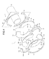
- figure 2 presents an exploded view of the sealed pipe passage of the figure 1 .
- the sealed passage 1 is made by means of a device comprising a support 2 comprising a hole and intended to be fixed on a partition around a passage opening for a conduit C.
- the support 2 comprises two parts 2a and 2b intended to be juxtaposed so as to form the support 2 around the conduit C.
- the support 2 comprises, on the perimeter of the hole, a receiving zone 3 of an annular seal 4 and a holding ring 5.
- the support 2 also includes angles (not shown) for maintaining the support for attachment to the partition.
- the reception zone 3 comprises bores 6 adapted to receive holding screws.
- the annular seal 4 is made of flexible and elastic material such as rubber or a soft and elastic metal. It comprises two portions 4a and 4b partially annular, that is to say in the form of truncated ring. Each partially annular portion 4a and 4b comprises a generally semicylindrical proximal portion 41 intended to cooperate with the conduit C, a distal portion 42 intended to cooperate with the retaining ring 5 and the support 2, and an intermediate portion 43 located between the proximal portion 41 and the distal portion 42.
- each partially annular portion 4a and 4b form a semicircle, or half a ring.
- the proximal portion 41 of a partially annular portion 4a may cooperate contiguously with the proximal portion 41 of the complementary partial annular portion 4b when the two partially annular portions 4a and 4b are assembled.
- each partially annular portion 4a and 4b each define more than half of a ring, and more particularly two-thirds of a ring, ie 240 °.
- their intermediate portion 43 is partially superimposed on a sector of at least about 60 ° between the support 2 and the fixing ring 7, on the surface separating the pipe C from the circular edge of the support 2.
- the covering between the two intermediate parts 43 thus makes it possible to maintain the tightness of the sealed passage device 1 even when the conduit C is caused to move relative to the support 2.
- the retaining ring 5 also comprises two semicircular parts 5a and 5b intended to be juxtaposed so as to form the retaining ring 5 serving to hold the annular seal 4, and more particularly the distal portions 42 of the partially annular portions 4a. and 4b, against the zone 3 for receiving the support 2.
- the junction between the parts 5a and 5b of the retaining ring 5 is positioned so as not to be located opposite the junction between the distal portions 42 of the partially annular portions 4a and 4b.
- the portions 5a and 5b of the holding ring 5 are angularly displaced by a quarter turn, ie 90 °, relative to the distal portions 42 of the partially annular portions 4a and 4b so as to improve the sealing of the device 1.
- the distal portions 42 of the annular seal 4 comprise orifices 8 and the retaining ring 5 comprises orifices 9.
- the orifices 8 and 9 of the annular seal 4 and of the retaining ring 5 are intended to be positioned facing the bores. 6 of the zone 3 receiving the support 2 for mounting the sealing device 1 with screws holding the annular seal 4 clamped between the support and the retaining ring 5.
- the annular seal 4 is fixed on the conduit C with the aid of a fixing ring 7 which may for example be a clamping collar.
- the fixing ring 7 bears on the proximal portions 41 of the partially annular portions 4a and 4b so as to clamp the proximal portions of the annular seal 4 against the duct C and thus ensure tightness at the level of the duct C.
- the juxtaposition , and therefore the non-overlap of the proximal portions 41 of the partially annular portions 4a and 4b allows the fixing ring 7 to ensure a good seal when clamped on the conduit C.
- the sealed passage device 1 allows, thanks in particular to the overlap of the intermediate portions 42 of the partially annular portions 4a and 4b, to seal even when the conduit C moves relative to the support 2.
- the fixing ring 17 is shaped so as to comprise a radial shoulder 170.
- the fixing ring 17 comprises two parts 17a and 17b intended to be assembled directly on the conduit C so as to form a ring having a shoulder 170 against which the annular seal 14 can abut to ensure sealing of the sealing device 1 between the conduit C and the annular seal 14.
- the annular seal 14 comprises two flat seals 14a and 14b mounted on either side of the shoulder 170 of the fixing ring 17.
- the two flat seals 14a and 14b are made of deformable material such as rubber or an elastic metal and flexible. They ensure the tightness of the passage even when the conduit C is moved relative to the support 2.
- Each portion 17a and 17b of the fastening ring 17 comprises assembly tabs 171 whose dimensions are smaller than the shoulder 170. Due to their dimensions relative to those of the shoulder, the assembly tabs 171 allow to assemble the fixing ring 17 around the duct C without hindering the annular plates 14a and 14b bearing on the shoulder 170.
- Each annular seal 14a and 14b is made from two identical semicircular half-joints 140 assembled by juxtaposition.
- Each semi-circular half-seal 140 comprises a proximal portion 141 and a distal portion 142 with respect to the duct C.
- the proximal portion 141 of each semicircular half-seal 140 bears against the shoulder 170 of the annular ring. fixing 17.
- the seal is here obtained by the support of the seals 14a and 14b against the shoulder 170 of the fixing ring.
- each semicircular half-seal 140 comprises orifices 18 for fixing the annular seal 14 to the support 2.
- the two annular seals 14a and 14b are mounted so that the junction between the semicircular half-seals 140 of an annular seal 14a is disposed orthogonally at the junction between the semicircular half-seals 140 of the other annular seal 14b, while having the orifices 8 of an annular seal 14a facing the orifices 8 of the opposite annular seal 14b. In this way, the risk of leakage is reduced.
- the junction between the parts 5a and 5b of the retaining ring 5 is positioned orthogonally at the junction between the two semicircular half-seals 140 of the annular seal 14b directly in contact with the retaining ring 5, while maintaining the orifices 9 of the retaining ring aligned with the orifices 18 of the annular seals 14a and 14b.
- the support 2 also comprises centering studs 31 intended to cooperate with centering orifices 32 made on the distal portions 142 of the annular seals 14a and 14b, and with centering orifices 33 made in the holding ring 5.
Landscapes
- Engineering & Computer Science (AREA)
- General Engineering & Computer Science (AREA)
- Mechanical Engineering (AREA)
- Architecture (AREA)
- Civil Engineering (AREA)
- Structural Engineering (AREA)
- Gasket Seals (AREA)
Abstract
Description
- L'invention concerne le passage étanche d'une tuyauterie à travers une cloison, et plus particulièrement le passage étanche d'une tuyauterie permettant de conserver une liberté de mouvement d'un tuyau dans toutes les directions.
- Lors de la construction d'une pièce ou d'un bâtiment, il est généralement nécessaire de prévoir des arrivées externes pour le passage de conduits de fluides ou d'électricité dans la pièce ou le bâtiment. Le transport de fluides ou d'électricité peut être réalisé de différentes manières selon les besoins.
- Dans le cas d'un transport de liquide, par exemple, il est généralement nécessaire d'utiliser des conduits ou tuyaux rigides qui passent au travers d'une ou de plusieurs cloisons via des orifices de passage pour atteindre la pièce de destination. L'installation de cloisons et la réalisation des orifices sont fait parfois après le montage de tuyauteries.
- Pour éviter que l'orifice de passage créé dans chaque cloison ne permette le passage d'air depuis l'extérieur ou d'autres types d'intrusions, cet orifice est généralement comblé après l'insertion du tuyau, de manière à boucher l'orifice, et rendre le passage étanche. Selon les besoins, et selon les matériaux employés, l'étanchéité du passage permet également de réaliser une isolation phonique.
- Le passage d'un conduit au travers d'une cloison est susceptible de poser un certain nombre de problèmes lorsque le conduit et la cloison sont mis en mouvement, par exemple par dilatation, de manière indépendante l'un par rapport à l'autre en particulier lorsque les mouvements ne son pas en phase. L'étanchéité du passage peut alors être compromise. Le conduit peut être endommagé. Le risque de fuites est alors important.
- D'après des mesures réalisées, pour assurer de bonnes conditions de sécurité, il faut en moyenne qu'un tuyau possédant un diamètre de dimension d puisse subir dans l'orifice de passage une translation de plus ou moins 0,2*d dans les trois directions de l'espace, et une rotation de plus ou moins 15° dans les trois sens de rotation de l'espace, sans que l'étanchéité ne soit compromise. Ceci permet de maintenir une étanchéité par exemple en cas de séisme.
- Généralement, les conduits traversent les cloisons extérieures d'un bâtiment au travers d'un mur de soubassement en béton. Les passages dans ces murs sont réalisés après l'installation de la tuyauterie, sans étanchéité, et les conduits sont fixés à partir de fixations latérales empêchant tout déplacement latéral. En général, au mieux, seule la translation dans la direction du conduit est autorisée. De plus, les fixations latérales engendrent des charges supplémentaires sur la structure du conduit, et l'ajout de joints d'expansion, entraîne des coûts supplémentaires.
- Pour tenter de résoudre en partie ces problèmes, il est connu d'utiliser des panneaux d'isolation phonique à fixer sur la cloison autour de l'orifice de passage. L'orifice de passage est rempli de laine minérale pour réaliser une isolation phonique de l'orifice. La laine minérale est maintenue en place à l'aide de deux demi-plaques de scellement venant se fixer sur les panneaux. Les demi-plaques sont réalisées à partir d'une même plaque dans laquelle est découpé un trou dont le diamètre correspond à celui du conduit traversant le passage. La plaque est ensuite coupée en deux pour créer deux demi-plaques aptes à être fixées de part et d'autre du conduit.
- Cependant, une telle solution n'offre qu'un seul degré de liberté. En effet, seule la translation dans la direction du conduit est permise, ce qui peut au passage enlever la laine minérale.
- Au vu de ce qui précède, il est proposé de résoudre les problèmes mentionnés ci-dessus, et en particulier de conserver une liberté de déplacement et de rotation d'un conduit traversant une cloison dans toutes les directions de l'espace.
- L'invention a donc pour objet un dispositif de passage étanche pour tuyauterie, comprenant un anneau de fixation destiné à être fixé sur un conduit, un support destiné à être fixé sur une cloison autour d'un orifice de passage du conduit, et un joint annulaire déformable d'étanchéité disposé entre l'anneau de fixation et le support.
- La forme annulaire du joint permet d'épouser les contours du conduit. L'anneau de fixation destiné à être fixé sur le conduit coopère avec le joint annulaire pour créer une étanchéité autour du conduit. L'étanchéité du passage est finalisée par le maintien du joint sur le support de manière étanche. L'élasticité du joint permet au conduit de bouger par rapport à la cloison dans les trois directions de l'espace, tout en maintenant l'étanchéité du joint en assurant toujours des surfaces de contact entre les joints, et par conséquent du passage.
- De préférence, le dispositif de passage comprend un anneau de maintien apte à maintenir le joint annulaire contre le support.
- L'anneau de maintien permet par exemple de fixer le joint annulaire sur le support, par exemple en serrant le joint entre l'anneau de maintien et le support. De même, le support est pourvu d'un ensemble de cornières, par exemple au nombre de quatre, qui permettent son appui et son maintien aisé sur la cloison (non représentées).
- Avantageusement, l'anneau de maintien peut comprendre deux portions semi-circulaires s'assemblant pour former un anneau.
- En réalisant l'anneau de maintien à partir de deux portions semi-circulaires, il est possible de fixer l'anneau de maintien sur le support alors que la conduite de tuyauterie est déjà en place et relié au reste du système de tuyauterie.
- Dans un mode de réalisation, l'anneau de fixation peut être configuré de manière à serrer le joint annulaire sur le conduit. Pour cela il est fixé après le joint annulaire.
- Dans ce mode de réalisation, le joint annulaire peut avantageusement comprendre une première portion partiellement annulaire assemblée avec une seconde portion partiellement annulaire, la première portion partiellement annulaire et la seconde portion partiellement annulaire étant conformées pour se recouvrir au moins partiellement entre l'anneau de fixation et le support et former un joint annulaire étanche.
- La réalisation du joint annulaire à partir de deux portions partiellement annulaires, c'est-à-dire formant une portion d'anneau, permet d'appliquer les deux portions et de former un joint annulaire alors que le conduit est déjà en place dans l'orifice de passage et relié au reste du système de tuyauterie. Le recouvrement au moins partiel des deux portions annulaires permet de conserver l'étanchéité du joint, et par conséquent du passage, lorsque le conduit est déplacé ou tourné par rapport à la cloison dans les trois directions de l'espace.
- De préférence, les première et seconde portions annulaires se recouvrent sur un angle d'au moins 60° sur deux zones de recouvrement.
- Dans un autre mode de réalisation, l'anneau de fixation peut comprendre un épaulement annulaire sur lequel le joint annulaire est en appui.
- L'étanchéité entre le joint annulaire et le conduit est réalisé à l'aide de l'anneau de fixation fixé de manière étanche sur le conduit. On réalise ainsi une jonction étanche entre l'épaulement et le joint annulaire déformable.
- Dans ce mode de réalisation, le joint annulaire peut avantageusement comprendre deux joints annulaires comprenant chacune deux demi-joints semi-circulaires, les deux joints annulaires étant disposés de part et d'autre de l'épaulement annulaire de l'anneau de fixation de sorte que la jonction entre les deux demi-joints semi-circulaires d'un joint annulaire soit orthogonale à la jonction entre les deux demi-joints semi-circulaires de l'autrejoint.
- En positionnant deux demi-joints annulaires, de part et d'autre de l'épaulement de l'anneau de fixation, l'étanchéité est assurée même dans le cas de déplacements importants notamment dans la direction du conduit. De plus, en réalisant chacun des demi-joints annulaires en deux portions hémicirculaires, il est possible de monter le joint annulaire alors que le conduit est déjà en place et raccordé au reste du système de tuyauterie.
- Pour assurer l'étanchéité du joint, les deux demi-joints sont montés de sorte que la jonction entre les deux portions hémisphériques d'un demi-joint soit orthogonale à la jonction entre les deux portions hémisphériques de l'autre plaque. Les deux demi-joints ne se recouvrant pas, la jonction entre les deux demi-joints peut ne pas être étanche, notamment dans le cas où le conduit est déplacé par rapport à la cloison. En positionnant les deux jonctions orthogonalement l'une par rapport à l'autre, l'étanchéité du passage est ainsi en permanence maintenue, un demi-joint restant étanche même lorsque l'étanchéité de l'autre demi-joint est dégradée. Ceci permet d'assurer toujours une surface de contact.
- Avantageusement, le support de fixation, l'anneau de maintien et le joint annulaire peuvent comprendre des moyens complémentaires de centrage.
- Les moyens complémentaires de centrage permettent ainsi de positionner les deux demi-joints annulaires de manière à avoir les deux jonctions orthogonales.
- Le joint annulaire peut avantageusement être en matériau élastique de type caoutchouc ou métal souple et élastique, notamment à haute température.
- Selon un autre aspect, il est proposé une cloison étanche comprenant un orifice destiné à être traversé par un tuyau, comprenant un dispositif de passage étanche de tuyauterie tel que défini ci-dessus fixé sur au moins l'un des côtés de la cloison, autour de l'orifice.
- D'autres avantages et caractéristiques de l'invention apparaîtront à l'examen de la description détaillée de modes de réalisation, nullement limitatifs, et des dessins annexés, sur lesquels :
- les
figures 1 et2 illustrent respectivement de manière schématique une vue assemblée et une vue éclatée d'un passage étanche de tuyauterie selon un premier mode de réalisation de l'invention ; - les
figures 3 et4 représentent schématiquement une vue assemblée et une vue éclatée d'un passage étanche de tuyauterie selon un second mode de réalisation de l'invention. - Sur la
figure 1 est illustrée de manière une vue en perspective d'un passage étanche de tuyauterie selon un premier mode de réalisation de l'invention. - Pour faciliter la compréhension, la
figure 2 présente une vue éclatée du passage étanche de tuyauterie de lafigure 1 . - Comme on le voit, le passage étanche 1 est réalisé au moyen d'un dispositif comprenant un support 2 comportant un trou et destiné être fixé sur une cloison autour d'un orifice de passage pour un conduit C. Le support 2 comprend deux parties 2a et 2b destinées à être juxtaposées de manière à former le support 2 autour du conduit C. Le support 2 comprend, sur le périmètre du trou, une zone de réception 3 d'un joint annulaire 4 et d'un anneau de maintien 5. Le support 2 comporte également des cornières (non représentées) permettant le maintien du support en vue de sa fixation à la cloison. La zone de réception 3 comprend des alésages 6 aptes à recevoir des vis de maintien.
- Le joint annulaire 4 est réalisé en matière souple et élastique tel que du caoutchouc ou un métal souple et élastique. Il comprend deux portions 4a et 4b partiellement annulaires, c'est-à-dire en forme d'anneau tronqué. Chaque portion partiellement annulaire 4a et 4b comprend une partie proximale 41 globalement semi-cylindrique destinée à coopérer avec le conduit C, une partie distale 42 destinée à coopérer avec l'anneau de maintien 5 et le support 2, et une partie intermédiaire 43 située entre la portion proximale 41 et la portion distale 42.
- La partie proximale 41 et la partie distale 42 de chaque portion partiellement annulaire 4a et 4b forment un demi-cercle, ou la moitié d'un anneau. Ainsi, la partie proximale 41 d'une portion partiellement annulaire 4a peut coopérer de manière jointive avec la partie proximale 41 de la portion partiellement annulaire 4b complémentaire lorsque les deux portions partiellement annulaires 4a et 4b sont assemblées. Tel est également le cas des parties distales 42 des portions partiellement annulaires 4a et 4b. Par conséquent, lorsque les deux portions partiellement annulaires 4a et 4b sont correctement assemblées, les parties proximale 41 et distale 42 se juxtaposent.
- Au contraire, les portions intermédiaires 43 de chaque portion partiellement annulaire 4a et 4b définissent chacune plus de la moitié d'un anneau, et plus particulièrement les deux tiers d'un anneau, soit 240 °. Lorsque les portions partiellement annulaires 4a et 4b sont assemblées, leur partie intermédiaire 43 se superpose partiellement sur un secteur d'environ au moins 60° entre le support 2 et l'anneau de fixation 7, sur la surface séparant le tuyau C du bord circulaire du support 2. Le recouvrement entre les deux parties intermédiaires 43 permet ainsi de maintenir l'étanchéité du dispositif de passage étanche 1 même lorsque le conduit C est amené à bouger par rapport au support 2.
- L'anneau de maintien 5 comprend également deux parties 5a et 5b semi-circulaires destinées à être juxtaposées de manière à former l'anneau de maintien 5 servant à maintenir le joint annulaire 4, et plus particulièrement les parties distales 42 des portions partiellement annulaires 4a et 4b, contre la zone 3 de réception du support 2.
- La juxtaposition, et donc le non recouvrement des parties distales 42 des portions partiellement annulaires 4a et 4b permet à l'anneau de maintien 5 d'assurer un maintien efficace du joint 4 lorsqu'il est serré sur la zone 3 de réception du support 2, tout en assurant une bonne étanchéité, grâce au recouvrement des portions intermédiaires, même lorsque le conduit C est déplacé par rapport au joint.
- Pour éviter que des fuites n'apparaissent au niveau des jonctions où les parties 5a et 5b de l'anneau de maintien 5, les portions partiellement annulaires 4a et 4b, et les parties du support 2a et 2b se juxtaposent, la jonction entre les parties 5a et 5b de l'anneau de maintien 5 est positionnée de manière à ne pas être située en regard de la jonction entre les parties distales 42 des portions partiellement annulaires 4a et 4b. Autrement dit, les parties 5a et 5b de l'anneau de maintien 5 sont déplacées angulairement d'un quart de tour, soit 90°, par rapport aux parties distales 42 des portions partiellement annulaires 4a et 4b de manière à améliorer l'étanchéité du dispositif 1.
- Les parties distales 42 du joint annulaire 4 comprennent des orifices 8 et l'anneau de maintien 5 comprend des orifices 9. Les orifices 8 et 9 du joint annulaire 4 et de l'anneau de maintien 5 sont destinés à être positionnés en regard des alésages 6 de la zone 3 de réception du support 2 pour réaliser le montage du dispositif de passage étanche 1 à l'aide de vis maintenant le joint annulaire 4 serré entre le support et l'anneau de maintien 5.
- Le joint annulaire 4 est fixé sur le conduit C à l'aide d'un anneau de fixation 7 qui peut par exemple être un collier de serrage. L'anneau de fixation 7 vient en appui sur les parties proximales 41 des portions partiellement annulaires 4a et 4b de manière à serrer les parties proximales du joint annulaire 4 contre le conduit C et ainsi assurer l'étanchéité au niveau du conduit C. La juxtaposition, et donc le non recouvrement des parties proximales 41 des portions partiellement annulaires 4a et 4b permet à l'anneau de fixation 7 d'assurer une bonne étanchéité lorsqu'il est serré sur le conduit C.
- Une fois assemblé, le dispositif de passage 1 étanche permet, grâce notamment au recouvrement des parties intermédiaires 42 des portions partiellement annulaires 4a et 4b, d'assurer l'étanchéité même lorsque le conduit C se déplace par rapport au support 2.
- Pour assurer une meilleure étanchéité, et notamment une meilleure isolation phonique, il est possible d'installer deux passages étanches 1 de chaque côté de la cloison autour de l'orifice de passage par lequel passe un conduit C.
- Sur les
figures 3 et4 sont illustrées une vue en perspective et une vue éclatée d'un dispositif de passage étanche 10 pour tuyauterie selon un second mode de réalisation de l'invention. - Les éléments identiques au premier mode de réalisation portent des références identiques.
- Dans ce mode de réalisation, l'anneau de fixation 17 est conformé de manière à comprendre un épaulement radial 170. L'anneau de fixation 17 comprend deux parties 17a et 17b destinées à être assemblées directement sur le conduit C de manière à former un anneau comportant un épaulement 170 contre lequel le joint annulaire 14 peut venir en butée pour assurer l'étanchéité du dispositif de passage étanche 1 entre le conduit C et le joint annulaire 14.
- Le joint annulaire 14 comprend deux joints plats 14a et 14b montés de part d'autre de l'épaulement 170 de l'anneau de fixation 17. Les deux joints plats 14a et 14b sont réalisés en matériau déformable tel que du caoutchouc ou un métal élastique et souple. Ils assurent l'étanchéité du passage même lorsque le conduit C est déplacé par rapport au support 2.
- Chaque partie 17a et 17b de l'anneau de fixation 17 comprend des pattes d'assemblage 171 dont les dimensions sont inférieures à l'épaulement 170. Grâce à leurs dimensions par rapport à celles de l'épaulement, les pattes d'assemblage 171 permettent d'assembler l'anneau de fixation 17 autour du conduit C sans gêner les plaques annulaires 14a et 14b venant en appui sur l'épaulement 170.
- Chaque joint annulaire 14a et 14b est réalisé à partir de deux demi-joints semi-circulaires 140 identiques, assemblés par juxtaposition. Chaque demi-joint semi-circulaire 140 comprend une partie proximale 141 et une partie distale 142 par rapport au conduit C. La partie proximale 141 de chaque demi-joint semi-circulaire 140 est en appui contre l'épaulement 170 de l'anneau de fixation 17.
- Ainsi, contrairement au mode de réalisation décrit précédemment dans lequel l'étanchéité est obtenu en sollicitant le joint 4 contre le conduit C grâce à l'anneau de fixation, l'étanchéité est ici obtenu grâce à l'appui des joint 14a et 14b contre l'épaulement 170 de l'anneau de fixation.
- La partie distale 142 de chaque demi-joint semi-circulaire 140 comprend des orifices 18 pour la fixation du joint annulaire 14 sur le support 2.
- Les deux joints annulaires 14a et 14b sont montés de sorte que la jonction entre les demi-joints semi-circulaires 140 d'un joint 14a annulaire soit disposée orthogonalement à la jonction entre les demi-joints semi-circulaires 140 de l'autre joint annulaire 14b, tout en ayant les orifices 8 d'un joint annulaire 14a en regard des orifices 8 du joint annulaire opposé 14b. De cette manière, le risque de fuite est diminué.
- De façon similaire, la jonction entre les parties 5a et 5b de l'anneau de maintien 5 est positionnée orthogonalement à la jonction entre les deux demi-joints semi-circulaires 140 du joint annulaire 14b directement en contact avec l'anneau de maintien 5, tout en maintenant les orifices 9 de l'anneau de maintien alignés avec les orifices 18 des joints annulaires 14a et 14b.
- En outre, dans ce mode de réalisation, le support 2 comprend également des plots 31 de centrage destinés à coopérer avec des orifices de centrage 32 réalisés sur les parties distales 142 des joints annulaires 14a et 14b, et avec des orifices de centrage 33 réalisés dans l'anneau de maintien 5.
Claims (12)
- Dispositif de passage étanche (1, 10) pour tuyauterie, comprenant un anneau de fixation (7, 17) destiné à être fixé sur un conduit (C), un support (2) destiné à être fixé sur une cloison autour d'un orifice de passage du conduit (C), caractérisé en ce qu'il comprend un joint annulaire (4, 14) déformable d'étanchéité disposé entre l'anneau de fixation (7, 17) et le support (2).
- Dispositif de passage étanche (1, 10) selon la revendication 1, comprenant un anneau de maintien (5) apte à maintenir le joint annulaire (4, 14) contre le support (2).
- Dispositif de passage étanche (1, 10) selon l'une des revendications 1 et 2 dans lequel le support (2) comprend un ensemble de cornières de maintien du support sur la cloison.
- Dispositif de passage étanche (1, 10) selon la revendication 2, dans lequel l'anneau de maintien (5) comprend deux portions semi-circulaires (5a, 5b) s'assemblant pour former un anneau.
- Dispositif de passage étanche (1) selon l'une des revendications 1 à 4, dans lequel l'anneau de fixation (7) est configuré de manière à serrer le joint annulaire (4) sur le conduit (C).
- Dispositif de passage étanche (1) selon la revendication 5, dans lequel le joint annulaire (4) comprend une première portion partiellement annulaire (4a) assemblée avec une seconde portion partiellement annulaire (4b), la première portion partiellement annulaire (4a) et la seconde portion partiellement annulaire (4b) étant conformées pour se recouvrir au moins partiellement sur entre l'anneau de fixation (7) et le support (2) et former un joint annulaire étanche (4).
- Dispositif de passage étanche (1) selon la revendication 5, dans lequel les première et seconde portions partiellement annulaires (4a et 4b) se recouvrent sur un angle d'au moins 60° sur deux zones de recouvrement.
- Dispositif de passage étanche (10) selon l'une des revendications 1 à 4, dans lequel l'anneau de fixation (17) comprend un épaulement (170) annulaire sur lequel le joint annulaire (14) est en appui.
- Dispositif de passage étanche (10) selon la revendication 8, dans lequel le joint annulaire (14) comprend deux joints annulaires (141, 142) comprenant chacune deux demi-joints semi-circulaires (140), les deux joints annulaires (141, 124) étant disposés de part et d'autre de l'épaulement (170) annulaire de l'anneau de fixation (17) de sorte que la jonction entre les deux demi-joints semi-circulaires (140) d'un joint annulaire (14a ou 14b) soit orthogonale à la jonction entre les deux demi-joints semi-circulaires (140) de l'autre joint (14b ou 14a).
- Dispositif de passage étanche (10) selon la revendication 9, dans lequel le support (2), l'anneau de maintien (5) et le joint annulaire (14) comprennent des moyens complémentaires de centrage (31, 32, 33).
- Dispositif de passage étanche (10) selon l'une des revendications 1 à 10, dans lequel le joint annulaire (4, 14) est en matériau élastique de type caoutchouc, ou en métal élastique et souple.
- Cloison étanche comprenant un orifice destiné à être traversé par un conduit (C), caractérisé en ce qu'elle comprend au moins un dispositif de passage étanche (1, 10) pour tuyauterie selon l'une quelconque des revendications 1 à 11 fixé sur au moins l'un des côtés de la cloison autour de l'orifice.
Priority Applications (1)
| Application Number | Priority Date | Filing Date | Title |
|---|---|---|---|
| EP12306054.3A EP2703703B1 (fr) | 2012-09-04 | 2012-09-04 | Dispositif de passage étanche d'une cloison pour tuyauterie |
Applications Claiming Priority (1)
| Application Number | Priority Date | Filing Date | Title |
|---|---|---|---|
| EP12306054.3A EP2703703B1 (fr) | 2012-09-04 | 2012-09-04 | Dispositif de passage étanche d'une cloison pour tuyauterie |
Publications (2)
| Publication Number | Publication Date |
|---|---|
| EP2703703A1 true EP2703703A1 (fr) | 2014-03-05 |
| EP2703703B1 EP2703703B1 (fr) | 2015-08-19 |
Family
ID=46924378
Family Applications (1)
| Application Number | Title | Priority Date | Filing Date |
|---|---|---|---|
| EP12306054.3A Active EP2703703B1 (fr) | 2012-09-04 | 2012-09-04 | Dispositif de passage étanche d'une cloison pour tuyauterie |
Country Status (1)
| Country | Link |
|---|---|
| EP (1) | EP2703703B1 (fr) |
Cited By (7)
| Publication number | Priority date | Publication date | Assignee | Title |
|---|---|---|---|---|
| US9404606B2 (en) | 2013-05-07 | 2016-08-02 | Gabe Coscarella | Backplate for a utility box |
| EP3150891A1 (fr) * | 2015-09-29 | 2017-04-05 | HILTI Aktiengesellschaft | Passage de conduite destine a passer des conduites a travers un composant |
| CN108050306A (zh) * | 2017-11-27 | 2018-05-18 | 马鞍山市海华金属制品有限公司 | 一种多自由度运动的密封装置 |
| US10018287B2 (en) * | 2014-02-28 | 2018-07-10 | Gabe Coscarella | Weather barrier for a building penetration |
| CN110030436A (zh) * | 2019-03-21 | 2019-07-19 | 中国科学院微电子研究所 | 一种穿板密封装置 |
| US10773817B1 (en) | 2018-03-08 | 2020-09-15 | Northrop Grumman Systems Corporation | Bi-directional flow ram air system for an aircraft |
| US10787804B2 (en) | 2017-07-17 | 2020-09-29 | Gabe Coscarella | Weather barrier for a building penetration with a removable collar |
Families Citing this family (1)
| Publication number | Priority date | Publication date | Assignee | Title |
|---|---|---|---|---|
| US10167989B2 (en) | 2016-03-08 | 2019-01-01 | Northrop Grumman Systems Corporation | Multidirectionally deflectable mounting apparatus and method |
Citations (3)
| Publication number | Priority date | Publication date | Assignee | Title |
|---|---|---|---|---|
| US5810400A (en) * | 1996-07-11 | 1998-09-22 | Advanced Polymer Technology, Inc. | Flexible entry boot |
| US5988698A (en) * | 1997-07-08 | 1999-11-23 | Sergio M. Bravo | Flexible penetration fitting |
| EP2228577A1 (fr) * | 2009-03-10 | 2010-09-15 | DOYMA GmbH & Co | Dispositif d'étanchéité destiné à étanchéifier une percée |
-
2012
- 2012-09-04 EP EP12306054.3A patent/EP2703703B1/fr active Active
Patent Citations (3)
| Publication number | Priority date | Publication date | Assignee | Title |
|---|---|---|---|---|
| US5810400A (en) * | 1996-07-11 | 1998-09-22 | Advanced Polymer Technology, Inc. | Flexible entry boot |
| US5988698A (en) * | 1997-07-08 | 1999-11-23 | Sergio M. Bravo | Flexible penetration fitting |
| EP2228577A1 (fr) * | 2009-03-10 | 2010-09-15 | DOYMA GmbH & Co | Dispositif d'étanchéité destiné à étanchéifier une percée |
Cited By (10)
| Publication number | Priority date | Publication date | Assignee | Title |
|---|---|---|---|---|
| US9404606B2 (en) | 2013-05-07 | 2016-08-02 | Gabe Coscarella | Backplate for a utility box |
| US10018287B2 (en) * | 2014-02-28 | 2018-07-10 | Gabe Coscarella | Weather barrier for a building penetration |
| EP3150891A1 (fr) * | 2015-09-29 | 2017-04-05 | HILTI Aktiengesellschaft | Passage de conduite destine a passer des conduites a travers un composant |
| WO2017055237A1 (fr) * | 2015-09-29 | 2017-04-06 | Hilti Aktiengesellschaft | Passage de conduite permettant le passage de conduites à travers un élément de construction |
| US10566778B2 (en) | 2015-09-29 | 2020-02-18 | Hilti Aktiengesellschaft | Line feedthrough for feeding lines through a component |
| US10787804B2 (en) | 2017-07-17 | 2020-09-29 | Gabe Coscarella | Weather barrier for a building penetration with a removable collar |
| CN108050306A (zh) * | 2017-11-27 | 2018-05-18 | 马鞍山市海华金属制品有限公司 | 一种多自由度运动的密封装置 |
| CN108050306B (zh) * | 2017-11-27 | 2019-11-19 | 合肥海诺恒信息科技有限公司 | 一种多自由度运动的密封装置 |
| US10773817B1 (en) | 2018-03-08 | 2020-09-15 | Northrop Grumman Systems Corporation | Bi-directional flow ram air system for an aircraft |
| CN110030436A (zh) * | 2019-03-21 | 2019-07-19 | 中国科学院微电子研究所 | 一种穿板密封装置 |
Also Published As
| Publication number | Publication date |
|---|---|
| EP2703703B1 (fr) | 2015-08-19 |
Similar Documents
| Publication | Publication Date | Title |
|---|---|---|
| EP2703703B1 (fr) | Dispositif de passage étanche d'une cloison pour tuyauterie | |
| FR2551175A1 (fr) | Colliers de fixation de tuyaux et raccords de transition utilisables avec de tels colliers | |
| EP4071316B1 (fr) | Dispositif de drainage equipé d'un manchon de fixation pour construction, notamment un toit de batiment ou une terrasse | |
| JP2014111987A5 (fr) | ||
| FR2599109A1 (fr) | Diaphragme a aimant | |
| FR3030682A1 (fr) | Ensemble de canalisation pourvu d'un systeme de drainage. | |
| FR2588924A1 (fr) | Joint interieur souple d'etancheite pour compresseur | |
| FR2485685A1 (fr) | Joint etanche aux gaz pour le passage d'un conduit a travers une structure | |
| FR3005214A1 (fr) | Boite d'appareillage electrique | |
| US10683957B2 (en) | Pipe connecting joint | |
| BE1008705A3 (fr) | Raccord de fixation pour un tube annele. | |
| FR2820490A1 (fr) | Raccord de tuyau lateral | |
| FR2943116A1 (fr) | Equipement pour combler le pourtour d'un orifice menage dans une paroi pour permettre le passage d'un conduit | |
| FR2472123A1 (fr) | Element d'etancheite de conduits, notamment pour moteur a combustion interne | |
| EP1781980A1 (fr) | Raccord de piquage a fixation mecanique destine aux orifices de piquage de forme dite carree | |
| FR2528530A1 (fr) | Distributeur modulaire pour reseau double de canalisations de fluides | |
| KR20150090770A (ko) | 플랜지관 이음용 클램프 장치 | |
| EP1936764B1 (fr) | Dispositif d'éclissage de deux canalisations électriques | |
| FR3064716A1 (fr) | Systeme d'etancheite a fiabilite amelioree d'un ensemble fluidique | |
| FR2596495A1 (fr) | Dispositif pour relier fluidiquement deux pieces en mouvement de rotation relatif, et robot comprenant un tel dispositif | |
| FR2554538A1 (fr) | Joint d'etancheite pour branchement d'un element tubulaire sur un tuyau de plus grand diametre | |
| EP2237385B1 (fr) | Garniture de passe cable | |
| FR2960608A1 (fr) | Dispositif de reglage d’une fixation pour panneaux sur une surface etanche | |
| FR2956131A1 (fr) | Dispositif d'aide au raccordement d'un appareil de gestion d'un fluide, tel qu'un compteur d'eau, sur un circuit ou une canalisation. | |
| FR3040831A1 (fr) | Boite d'appareillage electrique |
Legal Events
| Date | Code | Title | Description |
|---|---|---|---|
| AK | Designated contracting states |
Kind code of ref document: A1 Designated state(s): AL AT BE BG CH CY CZ DE DK EE ES FI FR GB GR HR HU IE IS IT LI LT LU LV MC MK MT NL NO PL PT RO RS SE SI SK SM TR |
|
| AX | Request for extension of the european patent |
Extension state: BA ME |
|
| PUAI | Public reference made under article 153(3) epc to a published international application that has entered the european phase |
Free format text: ORIGINAL CODE: 0009012 |
|
| 17P | Request for examination filed |
Effective date: 20140708 |
|
| GRAP | Despatch of communication of intention to grant a patent |
Free format text: ORIGINAL CODE: EPIDOSNIGR1 |
|
| RIC1 | Information provided on ipc code assigned before grant |
Ipc: F16L 5/08 20060101ALI20150226BHEP Ipc: F16L 5/02 20060101AFI20150226BHEP |
|
| INTG | Intention to grant announced |
Effective date: 20150320 |
|
| GRAS | Grant fee paid |
Free format text: ORIGINAL CODE: EPIDOSNIGR3 |
|
| GRAA | (expected) grant |
Free format text: ORIGINAL CODE: 0009210 |
|
| AK | Designated contracting states |
Kind code of ref document: B1 Designated state(s): AL AT BE BG CH CY CZ DE DK EE ES FI FR GB GR HR HU IE IS IT LI LT LU LV MC MK MT NL NO PL PT RO RS SE SI SK SM TR |
|
| REG | Reference to a national code |
Ref country code: GB Ref legal event code: FG4D Free format text: NOT ENGLISH |
|
| REG | Reference to a national code |
Ref country code: CH Ref legal event code: EP |
|
| REG | Reference to a national code |
Ref country code: IE Ref legal event code: FG4D Free format text: LANGUAGE OF EP DOCUMENT: FRENCH |
|
| REG | Reference to a national code |
Ref country code: AT Ref legal event code: REF Ref document number: 744063 Country of ref document: AT Kind code of ref document: T Effective date: 20150915 |
|
| REG | Reference to a national code |
Ref country code: DE Ref legal event code: R096 Ref document number: 602012009738 Country of ref document: DE |
|
| REG | Reference to a national code |
Ref country code: AT Ref legal event code: MK05 Ref document number: 744063 Country of ref document: AT Kind code of ref document: T Effective date: 20150819 |
|
| REG | Reference to a national code |
Ref country code: FR Ref legal event code: PLFP Year of fee payment: 4 |
|
| REG | Reference to a national code |
Ref country code: LT Ref legal event code: MG4D |
|
| REG | Reference to a national code |
Ref country code: NL Ref legal event code: MP Effective date: 20150819 |
|
| PG25 | Lapsed in a contracting state [announced via postgrant information from national office to epo] |
Ref country code: FI Free format text: LAPSE BECAUSE OF FAILURE TO SUBMIT A TRANSLATION OF THE DESCRIPTION OR TO PAY THE FEE WITHIN THE PRESCRIBED TIME-LIMIT Effective date: 20150819 Ref country code: GR Free format text: LAPSE BECAUSE OF FAILURE TO SUBMIT A TRANSLATION OF THE DESCRIPTION OR TO PAY THE FEE WITHIN THE PRESCRIBED TIME-LIMIT Effective date: 20151120 Ref country code: LV Free format text: LAPSE BECAUSE OF FAILURE TO SUBMIT A TRANSLATION OF THE DESCRIPTION OR TO PAY THE FEE WITHIN THE PRESCRIBED TIME-LIMIT Effective date: 20150819 Ref country code: NO Free format text: LAPSE BECAUSE OF FAILURE TO SUBMIT A TRANSLATION OF THE DESCRIPTION OR TO PAY THE FEE WITHIN THE PRESCRIBED TIME-LIMIT Effective date: 20151119 Ref country code: LT Free format text: LAPSE BECAUSE OF FAILURE TO SUBMIT A TRANSLATION OF THE DESCRIPTION OR TO PAY THE FEE WITHIN THE PRESCRIBED TIME-LIMIT Effective date: 20150819 |
|
| PG25 | Lapsed in a contracting state [announced via postgrant information from national office to epo] |
Ref country code: PL Free format text: LAPSE BECAUSE OF FAILURE TO SUBMIT A TRANSLATION OF THE DESCRIPTION OR TO PAY THE FEE WITHIN THE PRESCRIBED TIME-LIMIT Effective date: 20150819 Ref country code: PT Free format text: LAPSE BECAUSE OF FAILURE TO SUBMIT A TRANSLATION OF THE DESCRIPTION OR TO PAY THE FEE WITHIN THE PRESCRIBED TIME-LIMIT Effective date: 20151221 Ref country code: SE Free format text: LAPSE BECAUSE OF FAILURE TO SUBMIT A TRANSLATION OF THE DESCRIPTION OR TO PAY THE FEE WITHIN THE PRESCRIBED TIME-LIMIT Effective date: 20150819 Ref country code: ES Free format text: LAPSE BECAUSE OF FAILURE TO SUBMIT A TRANSLATION OF THE DESCRIPTION OR TO PAY THE FEE WITHIN THE PRESCRIBED TIME-LIMIT Effective date: 20150819 Ref country code: IS Free format text: LAPSE BECAUSE OF FAILURE TO SUBMIT A TRANSLATION OF THE DESCRIPTION OR TO PAY THE FEE WITHIN THE PRESCRIBED TIME-LIMIT Effective date: 20151219 Ref country code: RS Free format text: LAPSE BECAUSE OF FAILURE TO SUBMIT A TRANSLATION OF THE DESCRIPTION OR TO PAY THE FEE WITHIN THE PRESCRIBED TIME-LIMIT Effective date: 20150819 Ref country code: AT Free format text: LAPSE BECAUSE OF FAILURE TO SUBMIT A TRANSLATION OF THE DESCRIPTION OR TO PAY THE FEE WITHIN THE PRESCRIBED TIME-LIMIT Effective date: 20150819 |
|
| PG25 | Lapsed in a contracting state [announced via postgrant information from national office to epo] |
Ref country code: NL Free format text: LAPSE BECAUSE OF FAILURE TO SUBMIT A TRANSLATION OF THE DESCRIPTION OR TO PAY THE FEE WITHIN THE PRESCRIBED TIME-LIMIT Effective date: 20150819 |
|
| REG | Reference to a national code |
Ref country code: DE Ref legal event code: R119 Ref document number: 602012009738 Country of ref document: DE |
|
| PG25 | Lapsed in a contracting state [announced via postgrant information from national office to epo] |
Ref country code: SK Free format text: LAPSE BECAUSE OF FAILURE TO SUBMIT A TRANSLATION OF THE DESCRIPTION OR TO PAY THE FEE WITHIN THE PRESCRIBED TIME-LIMIT Effective date: 20150819 Ref country code: DK Free format text: LAPSE BECAUSE OF FAILURE TO SUBMIT A TRANSLATION OF THE DESCRIPTION OR TO PAY THE FEE WITHIN THE PRESCRIBED TIME-LIMIT Effective date: 20150819 Ref country code: EE Free format text: LAPSE BECAUSE OF FAILURE TO SUBMIT A TRANSLATION OF THE DESCRIPTION OR TO PAY THE FEE WITHIN THE PRESCRIBED TIME-LIMIT Effective date: 20150819 Ref country code: IT Free format text: LAPSE BECAUSE OF FAILURE TO SUBMIT A TRANSLATION OF THE DESCRIPTION OR TO PAY THE FEE WITHIN THE PRESCRIBED TIME-LIMIT Effective date: 20150819 Ref country code: CZ Free format text: LAPSE BECAUSE OF FAILURE TO SUBMIT A TRANSLATION OF THE DESCRIPTION OR TO PAY THE FEE WITHIN THE PRESCRIBED TIME-LIMIT Effective date: 20150819 |
|
| REG | Reference to a national code |
Ref country code: CH Ref legal event code: PL |
|
| PG25 | Lapsed in a contracting state [announced via postgrant information from national office to epo] |
Ref country code: RO Free format text: LAPSE BECAUSE OF FAILURE TO SUBMIT A TRANSLATION OF THE DESCRIPTION OR TO PAY THE FEE WITHIN THE PRESCRIBED TIME-LIMIT Effective date: 20150819 Ref country code: MC Free format text: LAPSE BECAUSE OF FAILURE TO SUBMIT A TRANSLATION OF THE DESCRIPTION OR TO PAY THE FEE WITHIN THE PRESCRIBED TIME-LIMIT Effective date: 20150819 |
|
| PLBE | No opposition filed within time limit |
Free format text: ORIGINAL CODE: 0009261 |
|
| STAA | Information on the status of an ep patent application or granted ep patent |
Free format text: STATUS: NO OPPOSITION FILED WITHIN TIME LIMIT |
|
| REG | Reference to a national code |
Ref country code: IE Ref legal event code: MM4A |
|
| 26N | No opposition filed |
Effective date: 20160520 |
|
| PG25 | Lapsed in a contracting state [announced via postgrant information from national office to epo] |
Ref country code: IE Free format text: LAPSE BECAUSE OF NON-PAYMENT OF DUE FEES Effective date: 20150904 Ref country code: CH Free format text: LAPSE BECAUSE OF NON-PAYMENT OF DUE FEES Effective date: 20150930 Ref country code: LI Free format text: LAPSE BECAUSE OF NON-PAYMENT OF DUE FEES Effective date: 20150930 Ref country code: DE Free format text: LAPSE BECAUSE OF NON-PAYMENT OF DUE FEES Effective date: 20160401 |
|
| REG | Reference to a national code |
Ref country code: FR Ref legal event code: PLFP Year of fee payment: 5 |
|
| PG25 | Lapsed in a contracting state [announced via postgrant information from national office to epo] |
Ref country code: SI Free format text: LAPSE BECAUSE OF FAILURE TO SUBMIT A TRANSLATION OF THE DESCRIPTION OR TO PAY THE FEE WITHIN THE PRESCRIBED TIME-LIMIT Effective date: 20150819 |
|
| PG25 | Lapsed in a contracting state [announced via postgrant information from national office to epo] |
Ref country code: MT Free format text: LAPSE BECAUSE OF FAILURE TO SUBMIT A TRANSLATION OF THE DESCRIPTION OR TO PAY THE FEE WITHIN THE PRESCRIBED TIME-LIMIT Effective date: 20150819 |
|
| GBPC | Gb: european patent ceased through non-payment of renewal fee |
Effective date: 20160904 |
|
| PG25 | Lapsed in a contracting state [announced via postgrant information from national office to epo] |
Ref country code: BG Free format text: LAPSE BECAUSE OF FAILURE TO SUBMIT A TRANSLATION OF THE DESCRIPTION OR TO PAY THE FEE WITHIN THE PRESCRIBED TIME-LIMIT Effective date: 20150819 Ref country code: SM Free format text: LAPSE BECAUSE OF FAILURE TO SUBMIT A TRANSLATION OF THE DESCRIPTION OR TO PAY THE FEE WITHIN THE PRESCRIBED TIME-LIMIT Effective date: 20150819 Ref country code: HU Free format text: LAPSE BECAUSE OF FAILURE TO SUBMIT A TRANSLATION OF THE DESCRIPTION OR TO PAY THE FEE WITHIN THE PRESCRIBED TIME-LIMIT; INVALID AB INITIO Effective date: 20120904 |
|
| PG25 | Lapsed in a contracting state [announced via postgrant information from national office to epo] |
Ref country code: CY Free format text: LAPSE BECAUSE OF FAILURE TO SUBMIT A TRANSLATION OF THE DESCRIPTION OR TO PAY THE FEE WITHIN THE PRESCRIBED TIME-LIMIT Effective date: 20150819 |
|
| REG | Reference to a national code |
Ref country code: FR Ref legal event code: PLFP Year of fee payment: 6 |
|
| PG25 | Lapsed in a contracting state [announced via postgrant information from national office to epo] |
Ref country code: GB Free format text: LAPSE BECAUSE OF NON-PAYMENT OF DUE FEES Effective date: 20160904 Ref country code: BE Free format text: LAPSE BECAUSE OF NON-PAYMENT OF DUE FEES Effective date: 20150930 Ref country code: HR Free format text: LAPSE BECAUSE OF FAILURE TO SUBMIT A TRANSLATION OF THE DESCRIPTION OR TO PAY THE FEE WITHIN THE PRESCRIBED TIME-LIMIT Effective date: 20150819 |
|
| PG25 | Lapsed in a contracting state [announced via postgrant information from national office to epo] |
Ref country code: LU Free format text: LAPSE BECAUSE OF NON-PAYMENT OF DUE FEES Effective date: 20150904 |
|
| PG25 | Lapsed in a contracting state [announced via postgrant information from national office to epo] |
Ref country code: TR Free format text: LAPSE BECAUSE OF FAILURE TO SUBMIT A TRANSLATION OF THE DESCRIPTION OR TO PAY THE FEE WITHIN THE PRESCRIBED TIME-LIMIT Effective date: 20150819 Ref country code: MK Free format text: LAPSE BECAUSE OF FAILURE TO SUBMIT A TRANSLATION OF THE DESCRIPTION OR TO PAY THE FEE WITHIN THE PRESCRIBED TIME-LIMIT Effective date: 20150819 |
|
| REG | Reference to a national code |
Ref country code: FR Ref legal event code: PLFP Year of fee payment: 7 |
|
| PG25 | Lapsed in a contracting state [announced via postgrant information from national office to epo] |
Ref country code: AL Free format text: LAPSE BECAUSE OF FAILURE TO SUBMIT A TRANSLATION OF THE DESCRIPTION OR TO PAY THE FEE WITHIN THE PRESCRIBED TIME-LIMIT Effective date: 20150819 |
|
| PGFP | Annual fee paid to national office [announced via postgrant information from national office to epo] |
Ref country code: FR Payment date: 20230818 Year of fee payment: 12 |