EP2703613A1 - Cylinder head and saddle-straddling type motor vehicle - Google Patents
Cylinder head and saddle-straddling type motor vehicle Download PDFInfo
- Publication number
- EP2703613A1 EP2703613A1 EP13182605.9A EP13182605A EP2703613A1 EP 2703613 A1 EP2703613 A1 EP 2703613A1 EP 13182605 A EP13182605 A EP 13182605A EP 2703613 A1 EP2703613 A1 EP 2703613A1
- Authority
- EP
- European Patent Office
- Prior art keywords
- exhaust pipe
- exhaust passage
- cylinder head
- exhaust
- end surface
- Prior art date
- Legal status (The legal status is an assumption and is not a legal conclusion. Google has not performed a legal analysis and makes no representation as to the accuracy of the status listed.)
- Granted
Links
Images





Classifications
-
- F—MECHANICAL ENGINEERING; LIGHTING; HEATING; WEAPONS; BLASTING
- F01—MACHINES OR ENGINES IN GENERAL; ENGINE PLANTS IN GENERAL; STEAM ENGINES
- F01N—GAS-FLOW SILENCERS OR EXHAUST APPARATUS FOR MACHINES OR ENGINES IN GENERAL; GAS-FLOW SILENCERS OR EXHAUST APPARATUS FOR INTERNAL-COMBUSTION ENGINES
- F01N13/00—Exhaust or silencing apparatus characterised by constructional features
- F01N13/08—Other arrangements or adaptations of exhaust conduits
- F01N13/10—Other arrangements or adaptations of exhaust conduits of exhaust manifolds
-
- F—MECHANICAL ENGINEERING; LIGHTING; HEATING; WEAPONS; BLASTING
- F01—MACHINES OR ENGINES IN GENERAL; ENGINE PLANTS IN GENERAL; STEAM ENGINES
- F01N—GAS-FLOW SILENCERS OR EXHAUST APPARATUS FOR MACHINES OR ENGINES IN GENERAL; GAS-FLOW SILENCERS OR EXHAUST APPARATUS FOR INTERNAL-COMBUSTION ENGINES
- F01N13/00—Exhaust or silencing apparatus characterised by constructional features
- F01N13/18—Construction facilitating manufacture, assembly, or disassembly
- F01N13/1838—Construction facilitating manufacture, assembly, or disassembly characterised by the type of connection between parts of exhaust or silencing apparatus, e.g. between housing and tubes, between tubes and baffles
- F01N13/1844—Mechanical joints
- F01N13/1855—Mechanical joints the connection being realised by using bolts, screws, rivets or the like
-
- F—MECHANICAL ENGINEERING; LIGHTING; HEATING; WEAPONS; BLASTING
- F02—COMBUSTION ENGINES; HOT-GAS OR COMBUSTION-PRODUCT ENGINE PLANTS
- F02F—CYLINDERS, PISTONS OR CASINGS, FOR COMBUSTION ENGINES; ARRANGEMENTS OF SEALINGS IN COMBUSTION ENGINES
- F02F1/00—Cylinders; Cylinder heads
- F02F1/24—Cylinder heads
- F02F1/42—Shape or arrangement of intake or exhaust channels in cylinder heads
- F02F1/4264—Shape or arrangement of intake or exhaust channels in cylinder heads of exhaust channels
Definitions
- the present invention relates to a cylinder head and a saddle-straddling type motor vehicle including the cylinder head.
- an exhaust pipe is attached between an exhaust pipe attachment portion of a cylinder head and a muffler.
- Exhaust gas generated in a combustion chamber of the engine is discharged to the outside from an exhaust port of the cylinder head through the exhaust pipe and the muffler (see JP 2010-7645 A , for example).
- an axis of the exhaust pipe attachment portion is formed to be inclined towards right with respect to a front and rear direction of a motorcycle. This enables the cylinder head to be connected to the muffler provided at the right rear of the motorcycle through the exhaust pipe.
- the exhaust pipe attachment portion of the cylinder head largely projects from a sidewall of the cylinder head.
- a size of the cylinder head increases in the front and rear direction of the motorcycle.
- An object of the present invention is to provide a cylinder head and a saddle-straddling type motor cycle in which an increase in size can be suppressed and an exhaust pipe can be connected to be inclined with respect to a sidewall.
- the exhaust passage leading the gas exhausted from the combustion chamber to the exhaust pipe is defined by the exhaust passage portion.
- the exhaust passage portion projects from the sidewall.
- the exhaust pipe is fitted into the exhaust pipe fitting portion of the exhaust passage portion.
- the bolt for attaching an exhaust pipe is fixed to the bolt fixing portion of the exhaust passage portion.
- At least part of the bolt fitting portion is provided outside of the exhaust pipe fixing portion in the exhaust passage radial direction as viewed from the cylinder axial direction.
- the downstream end surface of the exhaust pipe fitting portion in the exhaust passage axial direction is formed to be inclined with respect to the sidewall as viewed from the cylinder axial direction.
- downstream end surface of the bolt fixing portion is formed at the further upstream position than the downstream end surface of the exhaust pipe fitting portion in the exhaust passage axial direction.
- the exhaust pipe can be connected to be inclined with respect to the sidewall of the cylinder head while an increase in size of the cylinder head is suppressed.
- the exhaust passage portion has a larger region at the first portion that is the farthest from the sidewall than the second portion that is the closest to the sidewall.
- the component having a shape extending beyond the flange portion can be attached to the component attachment portion. Further, the attachment of the component to the component attachment portion and the removal of the component from the component attachment portion can be easily performed in a direction crossing the flange portion of the sidewall.
- the bolt for attaching an exhaust pipe is attached to the first and second bolt bearing surfaces.
- the second bolt bearing surface is provided at a position closer to the sidewall than the end surface of the flange portion such that the first bolt bearing surface comes closer to the sidewall. Therefore, the size of the cylinder head can be reduced in the direction vertical to the sidewall.
- the first bolt bearing surface is provided at a position farther from the sidewall than the second bolt bearing surface, a space for the component attachment portion can be sufficiently ensured at a position far from the sidewall in the exhaust passage portion. As a result, the component can be attached to the component attachment portion without interfering with the sidewall.
- the downstream end surface of the bolt fixing portion is formed at the further upstream position than the abutment surface in the exhaust passage axial direction, the size of the cylinder head can be reliably reduced in the direction vertical to the sidewall.
- a bolt hole of the bolt fixing portion can be formed at a position close to the center of the exhaust pipe fitting portion in the exhaust passage radial direction of the exhaust pipe fitting portion. This can prevent an increase in size of the bolt fixing portion in the exhaust passage radial direction.
- the single-cylinder engine is provided on the vehicle main body.
- the gas exhausted from the combustion chamber of the engine is led to the exhaust pipe through the exhaust passage portion of the cylinder head.
- the downstream end surface of the exhaust pipe fitting portion in the exhaust passage axial direction is formed to be inclined with respect to the sidewall as viewed from the cylinder axial direction. This enables the exhaust pipe to be compactly attached to the cylinder head.
- downstream end surface of the bolt fixing portion is formed at the further upstream position than the downstream end surface of the exhaust pipe fitting portion in the exhaust passage axial direction.
- the exhaust pipe can be connected to be inclined with respect to the sidewall of the cylinder head while the increase in size of the cylinder head is suppressed.
- the present invention enables the exhaust pipe to be connected to be inclined with respect to the sidewall of the cylinder head while an increase in size is suppressed.
- Fig. 1 is a side view of the motorcycle according to an embodiment of the present invention.
- Fig. 2 is a plan view of the motorcycle of Fig. 1 as viewed from above.
- Figs. 1 and 2 show the motorcycle 100 standing up to be vertical to the road surface.
- a front and rear direction L of the motorcycle 100 is indicated by an arrow.
- a width direction W of the motorcycle 100 is indicated by an arrow.
- the motorcycle 100 includes a vehicle body frame 80 constituted by a main-frame 80a and a sub-frame 80b.
- a head pipe 85 is provided at the front of the vehicle body frame 80, and a handle 81 is provided at the upper end of the head pipe 85.
- a front fork 82 is attached to the lower end of the head pipe 85.
- the front fork 82 is rotatable in a predetermined angular range with an axis of the head pipe 85 as a center.
- a front wheel 83 is supported at the lower end of the front fork 82 to be rotatable.
- a rear wheel 84 is supported at the rear of the vehicle body frame 80 to be rotatable.
- a single-cylinder engine 50 is provided at the center of the vehicle body frame 80.
- the engine 50 is constituted by a cylinder 51, a crank box 52 and a cylinder head 200.
- a combustion chamber is formed in the cylinder 51.
- An axial direction of the cylinder 51 (hereinafter referred to as a cylinder axial direction C) is indicated by a one-dot and dash line.
- the engine 50 is attached to the vehicle body frame 80 such that the cylinder axial direction C is inclined forward from the vertical direction.
- a valve mechanism 260, and an intake valve and an exhaust valve described below are provided in the cylinder head 200.
- the valve mechanism 260 includes an intake cam, an exhaust cam and a camshaft.
- the rear wheel 84 is rotated by rotational force of the engine 50.
- An exhaust device 10 that leads exhaust gas to the outside is connected to the cylinder head 200 of the engine 50.
- the exhaust device 10 includes an exhaust pipe 20 and a muffler (a silencer) 30.
- An exhaust passage portion 240 is provided at the front of the cylinder head 200.
- the muffler 30 is arranged on one side of a vehicle central line L1 in the width direction W.
- the muffler 30 is arranged on the right side of the vehicle central line L1 in the width direction W. Therefore, the exhaust pipe 20 of Fig. 1 is provided to extend obliquely forward rightward from the exhaust passage portion 240, bend rearward and further extend rearward to the muffler 30.
- the muffler 30 is provided to extend from the downstream end of the exhaust pipe 20 to the side of the rear wheel 84.
- the upstream end of the exhaust pipe 20 is connected to the exhaust passage portion 240 of the cylinder head 200 of the engine 50.
- the downstream end of the exhaust pipe 20 is inserted into the upstream end (an inlet) of the muffler 30.
- the outer peripheral portion of the upstream end of the muffler 30 is fastened by an attachment member such that the muffler 30 is fixed to the exhaust pipe 20.
- the exhaust gas generated by the combustion of a fuel-air mixture in the combustion chamber of the cylinder 51 is sent to the muffler 30 through the exhaust pipe 20.
- the exhaust gas is exhausted in the atmosphere through the muffler 30.
- the exhaust path of the engine 50 includes an exhaust passage 241 of the cylinder head 200, the exhaust pipe 20 and the muffler 30 in this order from the upstream to the downstream.
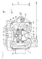
- Fig. 3 is a diagram of the cylinder head 200 as viewed from the cylinder axial direction C.
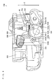
- Fig. 4 is a diagram of the cylinder head 200 as viewed from the side of the exhaust passage portion of Fig. 3 .
- the configuration of the cylinder head 200 according to the present embodiment will be described in the following with reference to Figs. 3 and 4 .
- the front and rear direction L and the width direction W are indicated by the arrows.
- the cylinder axial direction C of Fig. 1 is a direction vertical to the paper surface of Fig. 3 .
- the cylinder axial direction C is indicated by an arrow.
- the cylinder head 200 has sidewalls 201, 202, 203, 204.
- the sidewalls 201, 202 are formed to be opposite to each other and extend in the width direction W.
- the sidewalls 203, 204 are formed to be opposite to each other and to connect the both ends of the sidewall 201 and the both ends of the sidewall 202.
- a space V is defined by the four sidewalls 201 to 204.
- One or plurality of (two in this example) intake valves 210, one or plurality of (two in this example) exhaust valves 220 and the valve mechanism 260 of Fig. 1 are stored in the space V of the cylinder head 200. In Fig. 3 , the valve mechanism 260 is not shown.
- the plurality of intake valves 210 are provided at a plurality of intake holes to be opened/closed, and the plurality of exhaust valves 220 are provided at a plurality of exhaust holes to be capable of opening/closing.
- the plurality of intake valves 210 and the plurality of exhaust valves 220 are opened/closed by the valve mechanism 260 of Fig. 1 .
- a flange portion 205 projecting outward is formed at the upper ends of the sidewalls 201 to 204.
- the upper surface of the flange portion 205 is formed to be vertical to the cylinder axial direction C and flat.
- the upper portion of the opening of the cylinder head 200 is closed by a cylinder head cover 250 of Fig. 8 described below.
- the lower surface of the cylinder head cover 250 of Fig. 8 described below abuts against the upper surface of the flange portion 205.
- the outer surfaces of the sidewalls 201, 202 are formed to be parallel to the width direction W.
- An intake passage portion 230 is formed to project rearward from the sidewall 201.
- the intake passage portion 230 defines part of an intake passage (not shown) that leads air to the combustion chamber of the cylinder 51 of Fig. 1 . Air is supplied to the combustion chamber through the intake passage and the plurality of intake holes.
- the exhaust passage portion 240 is formed to project obliquely forward from the sidewall 202.
- the exhaust passage portion 240 defines part of the exhaust passage 241 that leads the exhaust gas exhausted from the combustion chamber to the exhaust pipe 20 of Fig. 1 .
- the exhaust passage 241 is formed such that two passages from the two exhaust holes join one passage, the one passage further passes through the exhaust passage portion 240 and opens at the downstream end of the exhaust passage portion 240. The exhaust gas is exhausted into the exhaust pipe 20 of Fig. 1 through the plurality of exhaust holes and the exhaust passage 241.
- the exhaust passage portion 240 has an exhaust pipe fitting portion 242, a plurality of bolt fixing portions 243 and a component attachment portion 244.
- the exhaust pipe 20 of Fig. 1 is fitted into the exhaust pipe fitting portion 242.
- the plurality of bolt fixing portions 243 are used for fixing bolts 21 for attaching an exhaust pipe of Fig. 8 described below.
- the two bolt fixing portions 243 are provided at the exhaust passage portion 240.
- An oxygen sensor 40 is attached to the component attachment portion 244.
- Fig. 5 is an enlarged view of the exhaust passage portion 240 of Fig. 3 .
- Fig. 6 is an enlarged view of the exhaust passage portion 240 of Fig. 4 .
- an axial direction of the exhaust passage 241 is referred to as an exhaust passage axial direction 241z.
- a radial direction of the exhaust passage 241 is referred to as an exhaust passage radial direction 241r.
- the exhaust passage 241 in the exhaust passage portion 240 is provided such that the exhaust passage axial direction 241z is inclined with respect to the front and rear direction L as viewed from the cylinder axial direction C.
- the exhaust passage 241 in the exhaust passage portion 240 is provided such that the exhaust passage axial direction 241z is inclined obliquely forward rightward with respect to the front and rear direction L.
- the exhaust pipe fitting portion 242 has a circular recess.
- the circular recess is constituted by a circular bottom surface and an annular projection that partially surrounds the bottom surface.
- the end surface of the annular projection is a downstream end surface 242e of the exhaust pipe fitting portion 242.
- the downstream end surface 242e of the exhaust pipe fitting portion 242 in the exhaust passage axial direction 241z is formed to be inclined with respect to the sidewall 202 as viewed from the cylinder axial direction C.
- the bottom surface in the recess of the exhaust pipe fitting portion 242 is an abutment surface 242C against which the end surface of the exhaust pipe 20 can abut.
- the abutment surface 242C is positioned at the further upstream than the downstream end surface 242e in the exhaust passage axial direction 241z.
- the exhaust passage 241 is opened at the center of the abutment surface 242C.
- the downstream end surfaces of the two bolt fixing portions 243 include bolt bearing surfaces 243A, 243B, respectively.
- the bolt bearing surfaces 243A, 243B are formed at the further upstream position than the abutment surface 242C of the exhaust pipe fitting portion 242 in the exhaust passage axial direction 241z.
- the bolt bearing surface 243A is provided at a position farther from the sidewall 202 than the bolt bearing surface 243B, and the bolt bearing surface 243B is provided at a position closer to the sidewall 202 than the end surface of the flange portion 205. That is, a distance LA from the bolt bearing surface 243A to the sidewall 202 is longer than a distance LB from the bolt bearing surface 243B to the sidewall 202. In this case, the bolt bearing surface 243B is provided at a position closer to the sidewall 202 than the end surface of the flange portion 205 such that the bolt bearing surface 243A comes closer to the sidewall 202. Therefore, a size of the cylinder head 200 can be reduced in a direction vertical to the sidewall 202.
- the bolt bearing surfaces 243A, 243B of the bolt fixing portions 243 are provided outside of the exhaust pipe fitting portion 242 in the exhaust passage radial direction 241r as viewed from the cylinder axial direction C.
- Bolt holes 243h are formed at the center of the bolt bearing surfaces 243A, 243B.
- the bolts 21 for attaching an exhaust pipe of Fig. 8 described below are inserted into the bolt holes 243h, respectively.
- Notches 242A, 242B are formed at portions respectively overlapping with the bolt bearing surfaces 243A, 243B in the exhaust passage radial direction 241r at the downstream end surface 242e of the exhaust pipe fitting portion 242 (an annular projection).
- the bottom surfaces of the notches 242A, 242B are formed to be linked to the bolt bearing surfaces 243A, 243B.
- the bolt holes 243h of the bolt bearing surfaces 243A, 243B can be formed at positions close to the center of the exhaust pipe fitting portion 242 in the exhaust passage radial direction 241r. As a result, an increase in size of the bolt fixing portions 243 in the exhaust passage radial direction 241r can be prevented.
- a portion of the downstream end surface 242e of the exhaust pipe fitting portion 242 that is the farthest from the sidewall 202 as viewed from the cylinder axial direction C is referred to as a first portion 244A.
- a portion of the downstream end surface 242e of the exhaust pipe fitting portion 242 that is the closest to the sidewall 202 as viewed from the cylinder axial direction C is referred to as a second portion 244B. That is, in the downstream end surface 242e of the exhaust pipe fitting portion 242, a distance from the first portion 244A to the sidewall 202 is the longest, and a distance from the second portion 244B to the sidewall 202 is the shortest.
- the bolt bearing surface 243A is provided at a position farther from the sidewall 202 than the bolt bearing surface 243B, a space for the component attachment portion 244 can be sufficiently ensured at a position far from the sidewall 202 in the exhaust passage portion 240.
- the component attachment portion 244 is provided at a position closer to the first portion 244A than the second portion 244B in the exhaust passage radial direction 241r.
- the exhaust passage portion 240 has a larger region at the first portion 244A than the second portion 244B.
- the component attachment portion 244 is arranged outside of an outer periphery of the flange portion 205 as viewed from the cylinder axial direction C.
- the oxygen sensor 40 having a shape extending beyond the flange portion 205 can be attached to the component attachment portion 244. Further, attachment of the components to the component attachment portion 244 and removal of the components from the component attachment portion 244 in a direction crossing the flange portion 205 of the sidewall 202 can be easily performed.
- the bolt bearing surface 243A may be formed such that a plane including the bolt bearing surface 243A intersects with the component attachment portion 244 as viewed from the cylinder axial direction C.
- the bolt bearing surface 243A may be formed such that the plane including the bolt bearing surface 243A is positioned at the further upstream than the component attachment portion 244 as viewed from the cylinder axial direction C. In this case, because the bolt bearing surface 243A sufficiently comes closer to the sidewall 202, the size of the cylinder head 200 can be sufficiently reduced in the direction vertical to the sidewall 202.
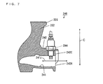
- Fig. 7 is a cross sectional view taken along the exhaust passage axial direction 241z of the exhaust passage portion 240 of Fig. 3 .
- the oxygen sensor 40 is attached to the component attachment portion 244 of the exhaust passage portion 240 in parallel to the cylinder axial direction C.
- an oxygen detector provided at the tip end of the oxygen sensor 40 is arranged in the exhaust passage 241.
- concentration of oxygen of the exhaust gas exhausted from the combustion chamber of the cylinder 51 through the exhaust passage 241 can be measured by the oxygen sensor 40.
- a temperature of the oxygen sensor 40 rises due to the heat in the combustion chamber. This enables the rise time of the oxygen sensor 40 to be shortened.
- Fig. 8 is a diagram showing the directional relationship between the cylinder head 200 and the motorcycle 100. As shown in Fig. 8 , the cylinder head 200 is provided on the vehicle body frame 80 such that the sidewalls 201, 202 are facing the front and rear of the motorcycle 100, respectively.
- the cylinder head cover 250 is attached to the upper surface of the flange portion 205 of Fig. 3 of the cylinder head 200.
- the exhaust pipe 20 is fitted into the recess of the exhaust pipe fitting portion 242.
- the exhaust pipe 20 is fixed to the bolt holes 243h of the bolt bearing surfaces 243A, 243B of the bolt fixing portions 243 by the bolts 21 for attaching an exhaust pipe 20.
- the exhaust pipe 20 is connected to the exhaust pipe fitting portion 242.
- the downstream end surface 242e of the exhaust pipe fitting portion 242 of the cylinder head 200 is inclined to one side (right side in the present embodiment) with respect to the front and rear direction L as viewed from the up-and-down direction of the motorcycle 100.
- the muffler 30 is provided on the one side (right side in the present embodiment) in the width direction W of the vehicle body frame 80.
- the exhaust passage portion 240 projects from the sidewall 202 in the cylinder head 200 according to the present embodiment.
- the bolt bearing surfaces 243A, 243B of the bolt fixing portions 243 of the exhaust passage portion 240 are provided outside of the exhaust pipe fitting portion 242 of the exhaust passage portion 240 in the exhaust passage radial direction 241r.
- the downstream end surface 242e of the exhaust pipe fitting portion 242 in the exhaust passage axial direction 241z is formed to be inclined with respect to the sidewall 202 as viewed from the cylinder axial direction C. This enables the exhaust pipe 20 to be compactly attached to the cylinder head 200.
- the bolt bearing surfaces 243A, 243B of the bolt fixing portions 243 are formed at the further upstream position than the lower end surface 242e of the exhaust pipe fitting portion 242 in the exhaust passage axial direction 241z.
- a distance from the sidewall 202 to a portion of the bolt fixing portion 243 that is the farthest is smaller as compared with the case in which the bolt bearing surfaces 243A, 243B and the downstream end surface 242e of the exhaust pipe fitting portion 242 are arranged on the same plane. Therefore, the size of the cylinder head 200 is reduced in the direction vertical to the sidewall 202, that is, the front and rear direction L of the vehicle body of the motorcycle 100.
- the exhaust pipe 20 can be connected to be inclined with respect to the sidewall 202 of the cylinder head 200 while the increase in size of the cylinder 200 is suppressed. Further, the size of the cylinder head 200 is reduced in the direction vertical to the sidewall 202.
- a number of the cylinder heads 200 that can be manufactured from one mold may be increased. As a result, productivity of the cylinder head 200 can be improved.
- the engine 50 is an example of an engine
- the cylinder head 200 is an example of a cylinder head
- the valve mechanism 260 is an example of a valve mechanism
- the space V is an example of a space
- the sidewall 202 is an example of a sidewall
- the flange portion 205 is an example of a flange portion.
- the exhaust pipe 20 is an example of an exhaust pipe
- the exhaust passage 241 is an example of an exhaust passage
- the exhaust passage portion 240 is an example of an exhaust passage portion
- the exhaust pipe fitting portion 242 is an example of an exhaust pipe fitting portion.
- the bolt 21 for attaching an exhaust pipe is an example of a bolt for attaching an exhaust pipe
- the bolt fixing portion 243 is an example of a bolt fixing portion
- the bolt bearing surfaces 243A, 243B are examples of first and second bolt bearing surfaces, respectively.
- the exhaust passage radial direction 241r is an example of an exhaust passage radial direction
- the exhaust passage axial direction 241z is an example of an exhaust passage axial direction
- the downstream end surface 242e is an example of a downstream end surface of the exhaust pipe fitting portion
- the cylinder axial direction C is an example of a cylinder axial direction.
- the oxygen sensor 40 is an example of a component or an oxygen sensor
- the component attachment portion 244 is an example of a component attachment portion
- the first portion 244A is an example of a first portion
- the second portion 244B is an example of a second portion.
- the abutment surface 242C is an example of an abutment surface
- the notches 242A, 242B are example of a notch
- the vehicle body frame 80 is an example of a vehicle
- the motorcycle 100 is an example of a saddle-straddling type motor vehicle
- the muffler 30 is an example of a silencer.
Landscapes
- Engineering & Computer Science (AREA)
- Chemical & Material Sciences (AREA)
- Combustion & Propulsion (AREA)
- Mechanical Engineering (AREA)
- General Engineering & Computer Science (AREA)
- Exhaust Silencers (AREA)
- Cylinder Crankcases Of Internal Combustion Engines (AREA)
Abstract
Description
- The present invention relates to a cylinder head and a saddle-straddling type motor vehicle including the cylinder head.
- In a vehicle including an engine, an exhaust pipe is attached between an exhaust pipe attachment portion of a cylinder head and a muffler. Exhaust gas generated in a combustion chamber of the engine is discharged to the outside from an exhaust port of the cylinder head through the exhaust pipe and the muffler (see
JP 2010-7645 A - In the cylinder head described in
JP 2010-7645 A - However, according to this configuration, because the exhaust pipe is attached to be inclined with respect to the front and rear direction of the motorcycle, the exhaust pipe attachment portion of the cylinder head largely projects from a sidewall of the cylinder head. Thus, a size of the cylinder head increases in the front and rear direction of the motorcycle.
- An object of the present invention is to provide a cylinder head and a saddle-straddling type motor cycle in which an increase in size can be suppressed and an exhaust pipe can be connected to be inclined with respect to a sidewall.
- (1) According to an aspect of the present invention, a cylinder head provided on a single-cylinder engine includes a sidewall that defines at least part of a space storing a valve mechanism, and an exhaust passage portion that defines an exhaust passage leading exhaust gas exhausted from a combustion chamber to an exhaust pipe and projects from the sidewall, wherein the exhaust passage portion has an exhaust pipe fitting portion into which the exhaust pipe is fitted and a bolt fixing portion for fixing of a bolt for attaching the exhaust pipe, at least part of the bolt fixing portion is provided outside of the exhaust pipe fitting portion in an exhaust passage radial direction as viewed from a cylinder axial direction, a downstream end surface of the exhaust pipe fitting portion in the exhaust passage axial direction is formed to be inclined with respect to the sidewall as viewed from the cylinder axial direction, and a downstream end surface of the bolt fixing portion in the exhaust passage axial direction is formed at a further upstream position than the downstream end surface of the exhaust pipe fitting portion in the exhaust passage axial direction.
- In this cylinder head, the exhaust passage leading the gas exhausted from the combustion chamber to the exhaust pipe is defined by the exhaust passage portion. The exhaust passage portion projects from the sidewall. The exhaust pipe is fitted into the exhaust pipe fitting portion of the exhaust passage portion. The bolt for attaching an exhaust pipe is fixed to the bolt fixing portion of the exhaust passage portion. At least part of the bolt fitting portion is provided outside of the exhaust pipe fixing portion in the exhaust passage radial direction as viewed from the cylinder axial direction. The downstream end surface of the exhaust pipe fitting portion in the exhaust passage axial direction is formed to be inclined with respect to the sidewall as viewed from the cylinder axial direction. Thus, the exhaust pipe can be compactly attached to the cylinder head.
- Further, the downstream end surface of the bolt fixing portion is formed at the further upstream position than the downstream end surface of the exhaust pipe fitting portion in the exhaust passage axial direction. Thus, a distance from the sidewall to a portion of the bolt fixing portion that is the farthest is smaller as compared with the case in which the downstream end surface of the bolt fixing portion and the downstream end surface of the exhaust pipe fitting portion are arranged on the same plane. Therefore, the size of the cylinder head is reduced in a direction vertical to the sidewall.
- As a result, the exhaust pipe can be connected to be inclined with respect to the sidewall of the cylinder head while an increase in size of the cylinder head is suppressed.
- (2) The exhaust passage portion may further have a component attachment portion for attaching a component. In this case, the component can be attached to the cylinder head by making the effective use of the exhaust passage portion. This prevents the increase in size of the cylinder head due to the attachment of the component.
- (3) The downstream end surface of the exhaust pipe fitting portion may have a first portion that is the farthest from the sidewall and a second portion that is the closest to the sidewall, as viewed from the cylinder axial direction, and the component attachment portion may be provided at a position closer to the first portion than the second portion in the exhaust passage radial direction.
- In this case, the exhaust passage portion has a larger region at the first portion that is the farthest from the sidewall than the second portion that is the closest to the sidewall. Thus, the component can be attached to the component attachment portion without interfering with the sidewall.
- (4) The cylinder head may further include a flange portion formed at an upper end of the sidewall, wherein the component attachment portion may be arranged outside of an outer periphery of the flange portion as viewed from the cylinder axial direction.
- In this case, the component having a shape extending beyond the flange portion can be attached to the component attachment portion. Further, the attachment of the component to the component attachment portion and the removal of the component from the component attachment portion can be easily performed in a direction crossing the flange portion of the sidewall.
- (5) The downstream end surface of the bolt fixing portion may include first and second bolt bearing surfaces, the first bolt bearing surface may be provided at a position farther from the sidewall than the second bolt bearing surface, and the second bolt bearing surface may be provided at a position closer to the sidewall than an end surface of the flange portion.
- In this case, the bolt for attaching an exhaust pipe is attached to the first and second bolt bearing surfaces. This enables the exhaust pipe to be reliably connected to the exhaust passage portion. Further, the second bolt bearing surface is provided at a position closer to the sidewall than the end surface of the flange portion such that the first bolt bearing surface comes closer to the sidewall. Therefore, the size of the cylinder head can be reduced in the direction vertical to the sidewall. Further, because the first bolt bearing surface is provided at a position farther from the sidewall than the second bolt bearing surface, a space for the component attachment portion can be sufficiently ensured at a position far from the sidewall in the exhaust passage portion. As a result, the component can be attached to the component attachment portion without interfering with the sidewall.
- (6) The first bolt bearing surface may be formed such that a plane including the first bolt bearing surface intersects with the component attachment portion as viewed from the cylinder axial direction. In this case, because the first bolt bearing surface sufficiently comes closer to the sidewall, the size of the cylinder head can be sufficiently reduced in the direction vertical to the sidewall.
- (7) The component may include an oxygen sensor. In this case, the concentration of oxygen of the gas exhausted from the combustion chamber can be measured by the oxygen sensor. Further, a temperature of the oxygen sensor rises due to the heat in the combustion chamber. This enables the rise time of the oxygen sensor to be shortened.
- (8) The exhaust pipe fitting portion may have an abutment surface against which an end surface of the exhaust pipe is abuttable, the abutment surface being inside the downstream end surface of the exhaust pipe fitting portion and at a further upstream position than the downstream end surface in the exhaust passage axial direction, and the downstream end surface of the bolt fixing portion may be formed at a further upstream position than the abutment surface in the exhaust passage axial direction.
- In this case, because the downstream end surface of the bolt fixing portion is formed at the further upstream position than the abutment surface in the exhaust passage axial direction, the size of the cylinder head can be reliably reduced in the direction vertical to the sidewall.
- (9) The downstream end surface of the exhaust pipe fitting portion may have a notch that is notched in the exhaust passage radial direction, the notch being at a portion overlapping with the downstream end surface of the bolt fixing portion in the exhaust passage radial direction.
- In this case, because the downstream end surface of the bolt fixing portion is formed to link with the downstream end surface of the exhaust pipe fitting portion, a bolt hole of the bolt fixing portion can be formed at a position close to the center of the exhaust pipe fitting portion in the exhaust passage radial direction of the exhaust pipe fitting portion. This can prevent an increase in size of the bolt fixing portion in the exhaust passage radial direction.
- (10) A saddle-straddling type motor vehicle according to another aspect of the present invention includes a vehicle body, a single-cylinder engine provided on the vehicle body, a cylinder head according to the one aspect of the present invention provided on the engine, and an exhaust pipe connected to the exhaust passage portion of the cylinder head.
- In this saddle-straddling type motor vehicle, the single-cylinder engine is provided on the vehicle main body. The gas exhausted from the combustion chamber of the engine is led to the exhaust pipe through the exhaust passage portion of the cylinder head.
- In the cylinder head, the downstream end surface of the exhaust pipe fitting portion in the exhaust passage axial direction is formed to be inclined with respect to the sidewall as viewed from the cylinder axial direction. This enables the exhaust pipe to be compactly attached to the cylinder head.
- Further, the downstream end surface of the bolt fixing portion is formed at the further upstream position than the downstream end surface of the exhaust pipe fitting portion in the exhaust passage axial direction. Thus, a distance from the sidewall to a portion of the bolt fixing portion that is the farthest is smaller as compared with the case in which the downstream end surface of the bolt fixing portion and the downstream end surface of the exhaust pipe fitting portion are arranged on the same plane. Therefore, the size of the cylinder head is reduced in the direction vertical to the sidewall.
- As a result, the exhaust pipe can be connected to be inclined with respect to the sidewall of the cylinder head while the increase in size of the cylinder head is suppressed.
- (11) The saddle-straddling type motor vehicle may further include a silencer provided at the exhaust pipe, wherein the silencer may be provided on one side in a width direction of the vehicle body, and a downstream end surface of the exhaust pipe fitting portion of the cylinder head may be formed to be inclined with respect to a front and rear direction of the vehicle main body as viewed from an up-and-down direction of the vehicle main body.
- In this case, because the downstream end surface of the exhaust pipe fitting portion of the cylinder head is inclined with respect to the front and rear direction of the vehicle main body, attachment of the exhaust pipe and the muffler and routing of the exhaust pipe are easily performed.
- The present invention enables the exhaust pipe to be connected to be inclined with respect to the sidewall of the cylinder head while an increase in size is suppressed.
- Other features, elements, characteristics, and advantages of the present invention will become more apparent from the following description of preferred embodiments of the present invention with reference to the attached drawings.
-
-
Fig. 1 is a side view of a motorcycle according to an embodiment of the present invention; -
Fig. 2 is a plan view of the motorcycle ofFig. 1 as viewed from above; -
Fig. 3 is a diagram of a cylinder head as viewed from a cylinder axial direction; -
Fig. 4 is a diagram of the cylinder head as viewed from a side of an exhaust passage portion ofFig. 3 ; -
Fig. 5 is an enlarged view of the exhaust passage portion ofFig. 3 ; -
Fig. 6 is an enlarged view of the exhaust passage portion ofFig. 4 ; -
Fig. 7 is a cross sectional view taken along an exhaust passage axial direction of the exhaust passage portion ofFig. 3 ; and -
Fig. 8 is a diagram showing a directional relationship between the cylinder head and the motorcycle. - A cylinder head and a motorcycle according to embodiments of the present invention will be described with reference to the drawings.
-
Fig. 1 is a side view of the motorcycle according to an embodiment of the present invention.Fig. 2 is a plan view of the motorcycle ofFig. 1 as viewed from above.Figs. 1 and2 show themotorcycle 100 standing up to be vertical to the road surface. A front and rear direction L of themotorcycle 100 is indicated by an arrow. Further, inFig. 2 , a width direction W of themotorcycle 100 is indicated by an arrow. - As shown in
Fig. 1 , themotorcycle 100 includes avehicle body frame 80 constituted by a main-frame 80a and asub-frame 80b. Ahead pipe 85 is provided at the front of thevehicle body frame 80, and ahandle 81 is provided at the upper end of thehead pipe 85. Afront fork 82 is attached to the lower end of thehead pipe 85. - In this state, the
front fork 82 is rotatable in a predetermined angular range with an axis of thehead pipe 85 as a center. Afront wheel 83 is supported at the lower end of thefront fork 82 to be rotatable. Arear wheel 84 is supported at the rear of thevehicle body frame 80 to be rotatable. A single-cylinder engine 50 is provided at the center of thevehicle body frame 80. Theengine 50 is constituted by acylinder 51, acrank box 52 and acylinder head 200. A combustion chamber is formed in thecylinder 51. An axial direction of the cylinder 51 (hereinafter referred to as a cylinder axial direction C) is indicated by a one-dot and dash line. In the present embodiment, theengine 50 is attached to thevehicle body frame 80 such that the cylinder axial direction C is inclined forward from the vertical direction. Avalve mechanism 260, and an intake valve and an exhaust valve described below are provided in thecylinder head 200. Thevalve mechanism 260 includes an intake cam, an exhaust cam and a camshaft. Therear wheel 84 is rotated by rotational force of theengine 50. - An
exhaust device 10 that leads exhaust gas to the outside is connected to thecylinder head 200 of theengine 50. Theexhaust device 10 includes anexhaust pipe 20 and a muffler (a silencer) 30. Anexhaust passage portion 240 is provided at the front of thecylinder head 200. - As shown in
Fig. 2 , themuffler 30 is arranged on one side of a vehicle central line L1 in the width direction W. In the present embodiment, themuffler 30 is arranged on the right side of the vehicle central line L1 in the width direction W. Therefore, theexhaust pipe 20 ofFig. 1 is provided to extend obliquely forward rightward from theexhaust passage portion 240, bend rearward and further extend rearward to themuffler 30. Themuffler 30 is provided to extend from the downstream end of theexhaust pipe 20 to the side of therear wheel 84. - The upstream end of the
exhaust pipe 20 is connected to theexhaust passage portion 240 of thecylinder head 200 of theengine 50. The downstream end of theexhaust pipe 20 is inserted into the upstream end (an inlet) of themuffler 30. The outer peripheral portion of the upstream end of themuffler 30 is fastened by an attachment member such that themuffler 30 is fixed to theexhaust pipe 20. - The exhaust gas generated by the combustion of a fuel-air mixture in the combustion chamber of the
cylinder 51 is sent to themuffler 30 through theexhaust pipe 20. The exhaust gas is exhausted in the atmosphere through themuffler 30. Thus, the exhaust path of theengine 50 includes anexhaust passage 241 of thecylinder head 200, theexhaust pipe 20 and themuffler 30 in this order from the upstream to the downstream. -
Fig. 3 is a diagram of thecylinder head 200 as viewed from the cylinder axial direction C.Fig. 4 is a diagram of thecylinder head 200 as viewed from the side of the exhaust passage portion ofFig. 3 . The configuration of thecylinder head 200 according to the present embodiment will be described in the following with reference toFigs. 3 and4 . InFig. 3 , the front and rear direction L and the width direction W are indicated by the arrows. The cylinder axial direction C ofFig. 1 is a direction vertical to the paper surface ofFig. 3 . InFig. 4 , the cylinder axial direction C is indicated by an arrow. - As shown in
Fig. 3 , thecylinder head 200 has sidewalls 201, 202, 203, 204. Thesidewalls sidewalls sidewall 201 and the both ends of thesidewall 202. A space V is defined by the foursidewalls 201 to 204. One or plurality of (two in this example)intake valves 210, one or plurality of (two in this example)exhaust valves 220 and thevalve mechanism 260 ofFig. 1 are stored in the space V of thecylinder head 200. InFig. 3 , thevalve mechanism 260 is not shown. The plurality ofintake valves 210 are provided at a plurality of intake holes to be opened/closed, and the plurality ofexhaust valves 220 are provided at a plurality of exhaust holes to be capable of opening/closing. The plurality ofintake valves 210 and the plurality ofexhaust valves 220 are opened/closed by thevalve mechanism 260 ofFig. 1 . - As shown in
Fig. 4 , aflange portion 205 projecting outward is formed at the upper ends of thesidewalls 201 to 204. The upper surface of theflange portion 205 is formed to be vertical to the cylinder axial direction C and flat. The upper portion of the opening of thecylinder head 200 is closed by acylinder head cover 250 ofFig. 8 described below. At this time, the lower surface of thecylinder head cover 250 ofFig. 8 described below abuts against the upper surface of theflange portion 205. - As shown in
Fig. 3 , the outer surfaces of thesidewalls intake passage portion 230 is formed to project rearward from thesidewall 201. Theintake passage portion 230 defines part of an intake passage (not shown) that leads air to the combustion chamber of thecylinder 51 ofFig. 1 . Air is supplied to the combustion chamber through the intake passage and the plurality of intake holes. - The
exhaust passage portion 240 is formed to project obliquely forward from thesidewall 202. Theexhaust passage portion 240 defines part of theexhaust passage 241 that leads the exhaust gas exhausted from the combustion chamber to theexhaust pipe 20 ofFig. 1 . In the present embodiment, theexhaust passage 241 is formed such that two passages from the two exhaust holes join one passage, the one passage further passes through theexhaust passage portion 240 and opens at the downstream end of theexhaust passage portion 240. The exhaust gas is exhausted into theexhaust pipe 20 ofFig. 1 through the plurality of exhaust holes and theexhaust passage 241. - The
exhaust passage portion 240 has an exhaust pipefitting portion 242, a plurality ofbolt fixing portions 243 and acomponent attachment portion 244. Theexhaust pipe 20 ofFig. 1 is fitted into the exhaust pipefitting portion 242. The plurality ofbolt fixing portions 243 are used for fixingbolts 21 for attaching an exhaust pipe ofFig. 8 described below. In the present embodiment, the twobolt fixing portions 243 are provided at theexhaust passage portion 240. Anoxygen sensor 40 is attached to thecomponent attachment portion 244. -
Fig. 5 is an enlarged view of theexhaust passage portion 240 ofFig. 3 .Fig. 6 is an enlarged view of theexhaust passage portion 240 ofFig. 4 . InFig. 5 , an axial direction of theexhaust passage 241 is referred to as an exhaust passageaxial direction 241z. InFig. 6 , a radial direction of theexhaust passage 241 is referred to as an exhaust passageradial direction 241r. - As shown in
Fig. 5 , theexhaust passage 241 in theexhaust passage portion 240 is provided such that the exhaust passageaxial direction 241z is inclined with respect to the front and rear direction L as viewed from the cylinder axial direction C. In the present embodiment, theexhaust passage 241 in theexhaust passage portion 240 is provided such that the exhaust passageaxial direction 241z is inclined obliquely forward rightward with respect to the front and rear direction L. - The exhaust pipe
fitting portion 242 has a circular recess. The circular recess is constituted by a circular bottom surface and an annular projection that partially surrounds the bottom surface. In the exhaust passageaxial direction 241z, the end surface of the annular projection is adownstream end surface 242e of the exhaust pipefitting portion 242. Thedownstream end surface 242e of the exhaust pipefitting portion 242 in the exhaust passageaxial direction 241z is formed to be inclined with respect to thesidewall 202 as viewed from the cylinder axial direction C. The bottom surface in the recess of the exhaust pipefitting portion 242 is anabutment surface 242C against which the end surface of theexhaust pipe 20 can abut. Theabutment surface 242C is positioned at the further upstream than thedownstream end surface 242e in the exhaust passageaxial direction 241z. Theexhaust passage 241 is opened at the center of theabutment surface 242C. - The downstream end surfaces of the two
bolt fixing portions 243 includebolt bearing surfaces abutment surface 242C of the exhaust pipefitting portion 242 in the exhaust passageaxial direction 241z. - Here, the
bolt bearing surface 243A is provided at a position farther from thesidewall 202 than thebolt bearing surface 243B, and thebolt bearing surface 243B is provided at a position closer to thesidewall 202 than the end surface of theflange portion 205. That is, a distance LA from thebolt bearing surface 243A to thesidewall 202 is longer than a distance LB from thebolt bearing surface 243B to thesidewall 202. In this case, thebolt bearing surface 243B is provided at a position closer to thesidewall 202 than the end surface of theflange portion 205 such that thebolt bearing surface 243A comes closer to thesidewall 202. Therefore, a size of thecylinder head 200 can be reduced in a direction vertical to thesidewall 202. - As shown in
Figs. 3 and6 , the bolt bearing surfaces 243A, 243B of thebolt fixing portions 243 are provided outside of the exhaust pipefitting portion 242 in the exhaust passageradial direction 241r as viewed from the cylinder axial direction C. Bolt holes 243h are formed at the center of the bolt bearing surfaces 243A, 243B. Thebolts 21 for attaching an exhaust pipe ofFig. 8 described below are inserted into thebolt holes 243h, respectively. -
Notches radial direction 241r at thedownstream end surface 242e of the exhaust pipe fitting portion 242 (an annular projection). In this case, the bottom surfaces of thenotches fitting portion 242 in the exhaust passageradial direction 241r. As a result, an increase in size of thebolt fixing portions 243 in the exhaust passageradial direction 241r can be prevented. - As shown in
Fig. 5 , a portion of thedownstream end surface 242e of the exhaust pipefitting portion 242 that is the farthest from thesidewall 202 as viewed from the cylinder axial direction C is referred to as afirst portion 244A. Similarly, a portion of thedownstream end surface 242e of the exhaust pipefitting portion 242 that is the closest to thesidewall 202 as viewed from the cylinder axial direction C is referred to as asecond portion 244B. That is, in thedownstream end surface 242e of the exhaust pipefitting portion 242, a distance from thefirst portion 244A to thesidewall 202 is the longest, and a distance from thesecond portion 244B to thesidewall 202 is the shortest. - In the present embodiment, because the
bolt bearing surface 243A is provided at a position farther from thesidewall 202 than thebolt bearing surface 243B, a space for thecomponent attachment portion 244 can be sufficiently ensured at a position far from thesidewall 202 in theexhaust passage portion 240. - Here, the
component attachment portion 244 is provided at a position closer to thefirst portion 244A than thesecond portion 244B in the exhaust passageradial direction 241r. In this case, theexhaust passage portion 240 has a larger region at thefirst portion 244A than thesecond portion 244B. Thus, theoxygen sensor 40 can be attached to thecomponent attachment portion 244 without interfering with thesidewall 202, and an increase in size of thecylinder head 200 due to the attachment of theoxygen sensor 40 is prevented. - Further, the
component attachment portion 244 is arranged outside of an outer periphery of theflange portion 205 as viewed from the cylinder axial direction C. In this case, theoxygen sensor 40 having a shape extending beyond theflange portion 205 can be attached to thecomponent attachment portion 244. Further, attachment of the components to thecomponent attachment portion 244 and removal of the components from thecomponent attachment portion 244 in a direction crossing theflange portion 205 of thesidewall 202 can be easily performed. - The
bolt bearing surface 243A may be formed such that a plane including thebolt bearing surface 243A intersects with thecomponent attachment portion 244 as viewed from the cylinder axial direction C. Alternatively, thebolt bearing surface 243A may be formed such that the plane including thebolt bearing surface 243A is positioned at the further upstream than thecomponent attachment portion 244 as viewed from the cylinder axial direction C. In this case, because thebolt bearing surface 243A sufficiently comes closer to thesidewall 202, the size of thecylinder head 200 can be sufficiently reduced in the direction vertical to thesidewall 202. -
Fig. 7 is a cross sectional view taken along the exhaust passageaxial direction 241z of theexhaust passage portion 240 ofFig. 3 . As shown inFig. 7 , theoxygen sensor 40 is attached to thecomponent attachment portion 244 of theexhaust passage portion 240 in parallel to the cylinder axial direction C. Here, an oxygen detector provided at the tip end of theoxygen sensor 40 is arranged in theexhaust passage 241. In this case, concentration of oxygen of the exhaust gas exhausted from the combustion chamber of thecylinder 51 through theexhaust passage 241 can be measured by theoxygen sensor 40. Further, a temperature of theoxygen sensor 40 rises due to the heat in the combustion chamber. This enables the rise time of theoxygen sensor 40 to be shortened. -
Fig. 8 is a diagram showing the directional relationship between thecylinder head 200 and themotorcycle 100. As shown inFig. 8 , thecylinder head 200 is provided on thevehicle body frame 80 such that thesidewalls motorcycle 100, respectively. - The
cylinder head cover 250 is attached to the upper surface of theflange portion 205 ofFig. 3 of thecylinder head 200. Theexhaust pipe 20 is fitted into the recess of the exhaust pipefitting portion 242. In this state, theexhaust pipe 20 is fixed to the bolt holes 243h of the bolt bearing surfaces 243A, 243B of thebolt fixing portions 243 by thebolts 21 for attaching anexhaust pipe 20. Thus, theexhaust pipe 20 is connected to the exhaust pipefitting portion 242. - According to this configuration, the
downstream end surface 242e of the exhaust pipefitting portion 242 of thecylinder head 200 is inclined to one side (right side in the present embodiment) with respect to the front and rear direction L as viewed from the up-and-down direction of themotorcycle 100. Further, as shown inFig. 1 , themuffler 30 is provided on the one side (right side in the present embodiment) in the width direction W of thevehicle body frame 80. Thus, attachment of theexhaust pipe 20 and themuffler 30 and routing of theexhaust pipe 20 are easily performed. - The
exhaust passage portion 240 projects from thesidewall 202 in thecylinder head 200 according to the present embodiment. Here, the bolt bearing surfaces 243A, 243B of thebolt fixing portions 243 of theexhaust passage portion 240 are provided outside of the exhaust pipefitting portion 242 of theexhaust passage portion 240 in the exhaust passageradial direction 241r. Thedownstream end surface 242e of the exhaust pipefitting portion 242 in the exhaust passageaxial direction 241z is formed to be inclined with respect to thesidewall 202 as viewed from the cylinder axial direction C. This enables theexhaust pipe 20 to be compactly attached to thecylinder head 200. - Further, the bolt bearing surfaces 243A, 243B of the
bolt fixing portions 243 are formed at the further upstream position than thelower end surface 242e of the exhaust pipefitting portion 242 in the exhaust passageaxial direction 241z. Thus, a distance from thesidewall 202 to a portion of thebolt fixing portion 243 that is the farthest is smaller as compared with the case in which the bolt bearing surfaces 243A, 243B and thedownstream end surface 242e of the exhaust pipefitting portion 242 are arranged on the same plane. Therefore, the size of thecylinder head 200 is reduced in the direction vertical to thesidewall 202, that is, the front and rear direction L of the vehicle body of themotorcycle 100. - As a result, the
exhaust pipe 20 can be connected to be inclined with respect to thesidewall 202 of thecylinder head 200 while the increase in size of thecylinder 200 is suppressed. Further, the size of thecylinder head 200 is reduced in the direction vertical to thesidewall 202. Thus, when thecylinder head 200 is manufactured by casting, a number of thecylinder heads 200 that can be manufactured from one mold may be increased. As a result, productivity of thecylinder head 200 can be improved. -
- (5-1) The
oxygen sensor 40 is attached to thecomponent attachment portion 244 in the embodiment described above, the invention is not limited to this. Another component may be attached to thecomponent attachment portion 244 instead of theoxygen sensor 40. Alternatively, theoxygen sensor 40 may be attached to a member positioned further downstream than theexhaust passage portion 240 such as theexhaust pipe 20 and the like. In this case, thecomponent attachment portion 244 does not have to be provided at theexhaust passage portion 240. - (5-2) The
oxygen sensor 40 is attached to thecomponent attachment portion 244 of theexhaust passage portion 240 in parallel to the cylinder axial direction C in the embodiment described above, the invention is not limited to this. Theoxygen sensor 40 may be attached to thecomponent attachment portion 244 of theexhaust passage portion 240 to be inclined with respect to the cylinder axial direction C. - (5-3) The
notches downstream end surface 242e of the exhaust pipefitting portion 242 in the embodiment described above, the invention is not limited to this. For example, when bolts having a small diameter are used, thenotches downstream end surface 242e of the exhaust pipefitting portion 242. - (5-4) The
motorcycle 100 is described as an example of the saddle-straddling type motor vehicle in the embodiment described above, the invention is not limited to this. This invention may be applied to another saddle-straddling type motor vehicle such as a motor tricycle, an ATV (All Terrain Vehicle) or the like. - In the following paragraphs, non-limiting examples of correspondences between various elements recited in the claims below and those described above with respect to various preferred embodiments of the present invention are explained.
- The
engine 50 is an example of an engine, thecylinder head 200 is an example of a cylinder head, thevalve mechanism 260 is an example of a valve mechanism, the space V is an example of a space, thesidewall 202 is an example of a sidewall and theflange portion 205 is an example of a flange portion. Theexhaust pipe 20 is an example of an exhaust pipe, theexhaust passage 241 is an example of an exhaust passage, theexhaust passage portion 240 is an example of an exhaust passage portion and the exhaust pipefitting portion 242 is an example of an exhaust pipe fitting portion. - The
bolt 21 for attaching an exhaust pipe is an example of a bolt for attaching an exhaust pipe, thebolt fixing portion 243 is an example of a bolt fixing portion and the bolt bearing surfaces 243A, 243B are examples of first and second bolt bearing surfaces, respectively. The exhaust passageradial direction 241r is an example of an exhaust passage radial direction, the exhaust passageaxial direction 241z is an example of an exhaust passage axial direction, thedownstream end surface 242e is an example of a downstream end surface of the exhaust pipe fitting portion and the cylinder axial direction C is an example of a cylinder axial direction. - The
oxygen sensor 40 is an example of a component or an oxygen sensor, thecomponent attachment portion 244 is an example of a component attachment portion, thefirst portion 244A is an example of a first portion and thesecond portion 244B is an example of a second portion. Theabutment surface 242C is an example of an abutment surface, thenotches vehicle body frame 80 is an example of a vehicle, themotorcycle 100 is an example of a saddle-straddling type motor vehicle and themuffler 30 is an example of a silencer. - While preferred embodiments of the present invention have been described above, it is to be understood that variations and modifications will be apparent to those skilled in the art without departing the scope and spirit of the present invention. The scope of the present invention, therefore, is to be determined solely by the following claims.
Claims (11)
- A cylinder head (200) provided on a single-cylinder engine (50), comprising:a sidewall (202) that defines at least part of a space (V) storing a valve mechanism (260); andan exhaust passage portion (240) that defines an exhaust passage (241) leading exhaust gas exhausted from a combustion chamber to an exhaust pipe (20) and projects from the sidewall (202), whereinthe exhaust passage portion (240) has an exhaust pipe fitting portion (242) into which the exhaust pipe (20) is fitted and a bolt fixing portion (243)for fixing of a bolt for attaching the exhaust pipe,at least part of the bolt fixing portion (243) is provided outside of the exhaust pipe fitting portion (242) in an exhaust passage radial direction as viewed from a cylinder axial direction,a downstream end surface (242e) of the exhaust pipe fitting portion (242) in the exhaust passage axial direction is formed to be inclined with respect to the sidewall (202) as viewed from the cylinder axial direction, anda downstream end surface of the bolt fixing portion (243) in the exhaust passage axial direction is formed at a further upstream portion than the downstream end surface (242e) of the exhaust pipe fitting portion (242) in the exhaust passage axial direction.
- The cylinder head (200) according to claim 1, wherein
the exhaust passage portion (240) further has a component attachment portion (244) for attaching a component (40). - The cylinder head (200) according to claim 2, wherein
the downstream end surface (242e) of the exhaust pipe fitting portion (242) has a first portion (244A) that is the farthest from the sidewall (202) and a second portion (244B) that is the closest to the sidewall (202), as viewed from the cylinder axial direction, and
the component attachment portion (244) is provided at a position closer to the first portion (244A) than the second portion (244B) in the exhaust passage radial direction. - The cylinder head (200) according to claim 2 or 3, further comprising:a flange portion (205) formed at an upper end of the sidewall (202), whereinthe component attachment portion (244) is arranged outside of an outer periphery of the flange portion (205) as viewed from the cylinder axial direction.
- The cylinder head (200) according to claim 4, wherein
the downstream end surface of the bolt fixing portion (243) includes first and second bolt bearing surfaces (243A, 243B),
the first bolt bearing surface (243A) is provided at a position farther from the sidewall (202) than the second bolt bearing surface (243B), and
the second bolt bearing surface (243B) is provided at a position closer to the sidewall (202) than an end surface of the flange portion (205). - The cylinder head (200) according to claim 5, wherein
the first bolt bearing surface (243A) is formed such that a plane including the first bolt bearing surface (243A) intersects with the component attachment portion (244) as viewed from the cylinder axial direction. - The cylinder head (200) according to any one of claims 2 to 6, wherein
the component (40) includes an oxygen sensor. - The cylinder head (200) according to any one of claims 1 to 7, wherein
the exhaust pipe fitting portion (242) has an abutment surface (242c) against which an end surface of the exhaust pipe (20) is abuttable, the abutment surface (242c) being inside the downstream end surface of the exhaust pipe fitting portion (242) and at a further upstream position than the downstream end surface in the exhaust passage axial direction, and
the downstream end surface of the bolt fixing portion (243) is formed at a further upstream position than the abutment surface (242c) in the exhaust passage axial direction. - The cylinder head (200) according to any one of claims 1 to 8, wherein
the downstream end surface (242e) of the exhaust pipe fitting portion (242) has a notch (242A, 242B) that is notched in the exhaust passage radial direction, the notch (242A, 242B) being at a portion overlapping with the downstream end surface of the bolt fixing portion (243) in the exhaust passage radial direction. - A saddle-straddling type motor vehicle comprising:a vehicle body;a single-cylinder engine (50) provided on the vehicle body;a cylinder head (200) according to any one of claims 1 to 9 provided on the engine (50); andan exhaust pipe (20) connected to the exhaust passage portion (240) of the cylinder head (200).
- The saddle-straddling type motor vehicle according to claim 10, further comprising:a silencer (30) provided at the exhaust pipe (20), whereinthe silencer (30) is provided on one side in a width direction of the vehicle body, anda downstream end surface of the exhaust pipe fitting portion (242) of the cylinder head (200) is formed to be inclined with respect to a front and rear direction of the vehicle main body as viewed from an up-and-down direction of the vehicle main body.
Applications Claiming Priority (1)
| Application Number | Priority Date | Filing Date | Title |
|---|---|---|---|
| JP2012194181A JP2014047768A (en) | 2012-09-04 | 2012-09-04 | Cylinder head, and saddle-straddling type vehicle |
Publications (2)
| Publication Number | Publication Date |
|---|---|
| EP2703613A1 true EP2703613A1 (en) | 2014-03-05 |
| EP2703613B1 EP2703613B1 (en) | 2014-11-12 |
Family
ID=49080782
Family Applications (1)
| Application Number | Title | Priority Date | Filing Date |
|---|---|---|---|
| EP20130182605 Active EP2703613B1 (en) | 2012-09-04 | 2013-09-02 | Cylinder head and saddle-straddling type motor vehicle |
Country Status (3)
| Country | Link |
|---|---|
| EP (1) | EP2703613B1 (en) |
| JP (1) | JP2014047768A (en) |
| ES (1) | ES2527205T3 (en) |
Cited By (1)
| Publication number | Priority date | Publication date | Assignee | Title |
|---|---|---|---|---|
| EP3326898A1 (en) * | 2016-11-28 | 2018-05-30 | Yamaha Hatsudoki Kabushiki Kaisha | Straddled vehicle |
Families Citing this family (1)
| Publication number | Priority date | Publication date | Assignee | Title |
|---|---|---|---|---|
| JP6057966B2 (en) * | 2014-09-30 | 2017-01-11 | 本田技研工業株式会社 | Exhaust gas sensor arrangement structure of internal combustion engine |
Citations (2)
| Publication number | Priority date | Publication date | Assignee | Title |
|---|---|---|---|---|
| US20090084098A1 (en) * | 2007-09-28 | 2009-04-02 | Yukihiro Tsubakino | Exhaust control device for vehicle engine |
| JP2010007645A (en) * | 2008-06-30 | 2010-01-14 | Honda Motor Co Ltd | Mounting structure of exhaust gas sensor of motorcycle |
-
2012
- 2012-09-04 JP JP2012194181A patent/JP2014047768A/en active Pending
-
2013
- 2013-09-02 EP EP20130182605 patent/EP2703613B1/en active Active
- 2013-09-02 ES ES13182605.9T patent/ES2527205T3/en active Active
Patent Citations (2)
| Publication number | Priority date | Publication date | Assignee | Title |
|---|---|---|---|---|
| US20090084098A1 (en) * | 2007-09-28 | 2009-04-02 | Yukihiro Tsubakino | Exhaust control device for vehicle engine |
| JP2010007645A (en) * | 2008-06-30 | 2010-01-14 | Honda Motor Co Ltd | Mounting structure of exhaust gas sensor of motorcycle |
Cited By (1)
| Publication number | Priority date | Publication date | Assignee | Title |
|---|---|---|---|---|
| EP3326898A1 (en) * | 2016-11-28 | 2018-05-30 | Yamaha Hatsudoki Kabushiki Kaisha | Straddled vehicle |
Also Published As
| Publication number | Publication date |
|---|---|
| ES2527205T3 (en) | 2015-01-21 |
| EP2703613B1 (en) | 2014-11-12 |
| JP2014047768A (en) | 2014-03-17 |
Similar Documents
| Publication | Publication Date | Title |
|---|---|---|
| JP6059816B2 (en) | Saddle riding vehicle | |
| JP2014189105A (en) | Motor cycle | |
| JP5771651B2 (en) | Fuel cap with breather mechanism | |
| US20170175670A1 (en) | Internal combustion engine, vehicle having the same, and method for manufacturing internal combustion engine | |
| JP2010007645A (en) | Mounting structure of exhaust gas sensor of motorcycle | |
| EP2703613B1 (en) | Cylinder head and saddle-straddling type motor vehicle | |
| JP2020079597A (en) | Internal combustion engine | |
| JP5874527B2 (en) | Intake control device for motorcycle | |
| JP2019182291A (en) | Injector arrangement structure | |
| JP5415363B2 (en) | Cylinder head structure of internal combustion engine | |
| JP6865078B2 (en) | Internal combustion engine cylinder head | |
| JP6280514B2 (en) | Exhaust passage structure of internal combustion engine | |
| JP2009057878A (en) | Engine and saddle type vehicle | |
| JP6340809B2 (en) | Engine cooling structure | |
| JP5983079B2 (en) | Motorcycle canister arrangement structure | |
| US9587719B2 (en) | Internal combustion engine and motorcycle equipped with the engine | |
| JP6897212B2 (en) | Engine exhaust purification device and vehicle | |
| JP7229334B2 (en) | Intake structure of internal combustion engine | |
| JP6612465B2 (en) | Internal combustion engine | |
| JP6446206B2 (en) | Vehicle cover structure | |
| JP6495060B2 (en) | In-cylinder internal combustion engine | |
| JP6319012B2 (en) | Engine breather room layout structure | |
| JP2005248794A (en) | Internal combustion engine | |
| JP6061368B2 (en) | Structure of cylinder head for water-cooled internal combustion engine | |
| CN102758675B (en) | An engine for bestriding-type vehicles |
Legal Events
| Date | Code | Title | Description |
|---|---|---|---|
| AK | Designated contracting states |
Kind code of ref document: A1 Designated state(s): AL AT BE BG CH CY CZ DE DK EE ES FI FR GB GR HR HU IE IS IT LI LT LU LV MC MK MT NL NO PL PT RO RS SE SI SK SM TR |
|
| AX | Request for extension of the european patent |
Extension state: BA ME |
|
| PUAI | Public reference made under article 153(3) epc to a published international application that has entered the european phase |
Free format text: ORIGINAL CODE: 0009012 |
|
| 17P | Request for examination filed |
Effective date: 20140318 |
|
| RBV | Designated contracting states (corrected) |
Designated state(s): AL AT BE BG CH CY CZ DE DK EE ES FI FR GB GR HR HU IE IS IT LI LT LU LV MC MK MT NL NO PL PT RO RS SE SI SK SM TR |
|
| RIC1 | Information provided on ipc code assigned before grant |
Ipc: F02F 1/42 20060101ALI20140514BHEP Ipc: F01N 13/18 20100101ALI20140514BHEP Ipc: F01N 13/10 20100101AFI20140514BHEP |
|
| GRAP | Despatch of communication of intention to grant a patent |
Free format text: ORIGINAL CODE: EPIDOSNIGR1 |
|
| INTG | Intention to grant announced |
Effective date: 20140620 |
|
| GRAS | Grant fee paid |
Free format text: ORIGINAL CODE: EPIDOSNIGR3 |
|
| GRAA | (expected) grant |
Free format text: ORIGINAL CODE: 0009210 |
|
| AK | Designated contracting states |
Kind code of ref document: B1 Designated state(s): AL AT BE BG CH CY CZ DE DK EE ES FI FR GB GR HR HU IE IS IT LI LT LU LV MC MK MT NL NO PL PT RO RS SE SI SK SM TR |
|
| REG | Reference to a national code |
Ref country code: GB Ref legal event code: FG4D |
|
| REG | Reference to a national code |
Ref country code: CH Ref legal event code: EP |
|
| REG | Reference to a national code |
Ref country code: AT Ref legal event code: REF Ref document number: 695917 Country of ref document: AT Kind code of ref document: T Effective date: 20141115 |
|
| REG | Reference to a national code |
Ref country code: IE Ref legal event code: FG4D |
|
| REG | Reference to a national code |
Ref country code: DE Ref legal event code: R096 Ref document number: 602013000455 Country of ref document: DE Effective date: 20141224 |
|
| REG | Reference to a national code |
Ref country code: ES Ref legal event code: FG2A Ref document number: 2527205 Country of ref document: ES Kind code of ref document: T3 Effective date: 20150121 |
|
| REG | Reference to a national code |
Ref country code: NL Ref legal event code: VDEP Effective date: 20141112 |
|
| REG | Reference to a national code |
Ref country code: AT Ref legal event code: MK05 Ref document number: 695917 Country of ref document: AT Kind code of ref document: T Effective date: 20141112 |
|
| PG25 | Lapsed in a contracting state [announced via postgrant information from national office to epo] |
Ref country code: PT Free format text: LAPSE BECAUSE OF FAILURE TO SUBMIT A TRANSLATION OF THE DESCRIPTION OR TO PAY THE FEE WITHIN THE PRESCRIBED TIME-LIMIT Effective date: 20150312 Ref country code: NL Free format text: LAPSE BECAUSE OF FAILURE TO SUBMIT A TRANSLATION OF THE DESCRIPTION OR TO PAY THE FEE WITHIN THE PRESCRIBED TIME-LIMIT Effective date: 20141112 Ref country code: FI Free format text: LAPSE BECAUSE OF FAILURE TO SUBMIT A TRANSLATION OF THE DESCRIPTION OR TO PAY THE FEE WITHIN THE PRESCRIBED TIME-LIMIT Effective date: 20141112 Ref country code: LT Free format text: LAPSE BECAUSE OF FAILURE TO SUBMIT A TRANSLATION OF THE DESCRIPTION OR TO PAY THE FEE WITHIN THE PRESCRIBED TIME-LIMIT Effective date: 20141112 Ref country code: IS Free format text: LAPSE BECAUSE OF FAILURE TO SUBMIT A TRANSLATION OF THE DESCRIPTION OR TO PAY THE FEE WITHIN THE PRESCRIBED TIME-LIMIT Effective date: 20150312 Ref country code: NO Free format text: LAPSE BECAUSE OF FAILURE TO SUBMIT A TRANSLATION OF THE DESCRIPTION OR TO PAY THE FEE WITHIN THE PRESCRIBED TIME-LIMIT Effective date: 20150212 |
|
| PG25 | Lapsed in a contracting state [announced via postgrant information from national office to epo] |
Ref country code: HR Free format text: LAPSE BECAUSE OF FAILURE TO SUBMIT A TRANSLATION OF THE DESCRIPTION OR TO PAY THE FEE WITHIN THE PRESCRIBED TIME-LIMIT Effective date: 20141112 Ref country code: AT Free format text: LAPSE BECAUSE OF FAILURE TO SUBMIT A TRANSLATION OF THE DESCRIPTION OR TO PAY THE FEE WITHIN THE PRESCRIBED TIME-LIMIT Effective date: 20141112 Ref country code: LV Free format text: LAPSE BECAUSE OF FAILURE TO SUBMIT A TRANSLATION OF THE DESCRIPTION OR TO PAY THE FEE WITHIN THE PRESCRIBED TIME-LIMIT Effective date: 20141112 Ref country code: RS Free format text: LAPSE BECAUSE OF FAILURE TO SUBMIT A TRANSLATION OF THE DESCRIPTION OR TO PAY THE FEE WITHIN THE PRESCRIBED TIME-LIMIT Effective date: 20141112 Ref country code: PL Free format text: LAPSE BECAUSE OF FAILURE TO SUBMIT A TRANSLATION OF THE DESCRIPTION OR TO PAY THE FEE WITHIN THE PRESCRIBED TIME-LIMIT Effective date: 20141112 Ref country code: CY Free format text: LAPSE BECAUSE OF FAILURE TO SUBMIT A TRANSLATION OF THE DESCRIPTION OR TO PAY THE FEE WITHIN THE PRESCRIBED TIME-LIMIT Effective date: 20141112 Ref country code: SE Free format text: LAPSE BECAUSE OF FAILURE TO SUBMIT A TRANSLATION OF THE DESCRIPTION OR TO PAY THE FEE WITHIN THE PRESCRIBED TIME-LIMIT Effective date: 20141112 Ref country code: GR Free format text: LAPSE BECAUSE OF FAILURE TO SUBMIT A TRANSLATION OF THE DESCRIPTION OR TO PAY THE FEE WITHIN THE PRESCRIBED TIME-LIMIT Effective date: 20150213 |
|
| PG25 | Lapsed in a contracting state [announced via postgrant information from national office to epo] |
Ref country code: SK Free format text: LAPSE BECAUSE OF FAILURE TO SUBMIT A TRANSLATION OF THE DESCRIPTION OR TO PAY THE FEE WITHIN THE PRESCRIBED TIME-LIMIT Effective date: 20141112 Ref country code: EE Free format text: LAPSE BECAUSE OF FAILURE TO SUBMIT A TRANSLATION OF THE DESCRIPTION OR TO PAY THE FEE WITHIN THE PRESCRIBED TIME-LIMIT Effective date: 20141112 Ref country code: RO Free format text: LAPSE BECAUSE OF FAILURE TO SUBMIT A TRANSLATION OF THE DESCRIPTION OR TO PAY THE FEE WITHIN THE PRESCRIBED TIME-LIMIT Effective date: 20141112 Ref country code: DK Free format text: LAPSE BECAUSE OF FAILURE TO SUBMIT A TRANSLATION OF THE DESCRIPTION OR TO PAY THE FEE WITHIN THE PRESCRIBED TIME-LIMIT Effective date: 20141112 Ref country code: CZ Free format text: LAPSE BECAUSE OF FAILURE TO SUBMIT A TRANSLATION OF THE DESCRIPTION OR TO PAY THE FEE WITHIN THE PRESCRIBED TIME-LIMIT Effective date: 20141112 |
|
| REG | Reference to a national code |
Ref country code: DE Ref legal event code: R097 Ref document number: 602013000455 Country of ref document: DE |
|
| PLBE | No opposition filed within time limit |
Free format text: ORIGINAL CODE: 0009261 |
|
| STAA | Information on the status of an ep patent application or granted ep patent |
Free format text: STATUS: NO OPPOSITION FILED WITHIN TIME LIMIT |
|
| 26N | No opposition filed |
Effective date: 20150813 |
|
| PG25 | Lapsed in a contracting state [announced via postgrant information from national office to epo] |
Ref country code: SI Free format text: LAPSE BECAUSE OF FAILURE TO SUBMIT A TRANSLATION OF THE DESCRIPTION OR TO PAY THE FEE WITHIN THE PRESCRIBED TIME-LIMIT Effective date: 20141112 |
|
| PG25 | Lapsed in a contracting state [announced via postgrant information from national office to epo] |
Ref country code: LU Free format text: LAPSE BECAUSE OF FAILURE TO SUBMIT A TRANSLATION OF THE DESCRIPTION OR TO PAY THE FEE WITHIN THE PRESCRIBED TIME-LIMIT Effective date: 20150902 Ref country code: MC Free format text: LAPSE BECAUSE OF FAILURE TO SUBMIT A TRANSLATION OF THE DESCRIPTION OR TO PAY THE FEE WITHIN THE PRESCRIBED TIME-LIMIT Effective date: 20141112 |
|
| REG | Reference to a national code |
Ref country code: IE Ref legal event code: MM4A |
|
| PG25 | Lapsed in a contracting state [announced via postgrant information from national office to epo] |
Ref country code: IE Free format text: LAPSE BECAUSE OF NON-PAYMENT OF DUE FEES Effective date: 20150902 |
|
| REG | Reference to a national code |
Ref country code: FR Ref legal event code: PLFP Year of fee payment: 4 |
|
| PG25 | Lapsed in a contracting state [announced via postgrant information from national office to epo] |
Ref country code: MT Free format text: LAPSE BECAUSE OF FAILURE TO SUBMIT A TRANSLATION OF THE DESCRIPTION OR TO PAY THE FEE WITHIN THE PRESCRIBED TIME-LIMIT Effective date: 20141112 |
|
| REG | Reference to a national code |
Ref country code: CH Ref legal event code: PL |
|
| PG25 | Lapsed in a contracting state [announced via postgrant information from national office to epo] |
Ref country code: HU Free format text: LAPSE BECAUSE OF FAILURE TO SUBMIT A TRANSLATION OF THE DESCRIPTION OR TO PAY THE FEE WITHIN THE PRESCRIBED TIME-LIMIT; INVALID AB INITIO Effective date: 20130902 Ref country code: BG Free format text: LAPSE BECAUSE OF FAILURE TO SUBMIT A TRANSLATION OF THE DESCRIPTION OR TO PAY THE FEE WITHIN THE PRESCRIBED TIME-LIMIT Effective date: 20141112 |
|
| PG25 | Lapsed in a contracting state [announced via postgrant information from national office to epo] |
Ref country code: LI Free format text: LAPSE BECAUSE OF NON-PAYMENT OF DUE FEES Effective date: 20160930 Ref country code: CH Free format text: LAPSE BECAUSE OF NON-PAYMENT OF DUE FEES Effective date: 20160930 |
|
| REG | Reference to a national code |
Ref country code: FR Ref legal event code: PLFP Year of fee payment: 5 |
|
| PG25 | Lapsed in a contracting state [announced via postgrant information from national office to epo] |
Ref country code: BE Free format text: LAPSE BECAUSE OF FAILURE TO SUBMIT A TRANSLATION OF THE DESCRIPTION OR TO PAY THE FEE WITHIN THE PRESCRIBED TIME-LIMIT Effective date: 20141112 |
|
| PG25 | Lapsed in a contracting state [announced via postgrant information from national office to epo] |
Ref country code: SM Free format text: LAPSE BECAUSE OF FAILURE TO SUBMIT A TRANSLATION OF THE DESCRIPTION OR TO PAY THE FEE WITHIN THE PRESCRIBED TIME-LIMIT Effective date: 20141112 |
|
| PG25 | Lapsed in a contracting state [announced via postgrant information from national office to epo] |
Ref country code: MK Free format text: LAPSE BECAUSE OF FAILURE TO SUBMIT A TRANSLATION OF THE DESCRIPTION OR TO PAY THE FEE WITHIN THE PRESCRIBED TIME-LIMIT Effective date: 20141112 |
|
| REG | Reference to a national code |
Ref country code: FR Ref legal event code: PLFP Year of fee payment: 6 |
|
| PG25 | Lapsed in a contracting state [announced via postgrant information from national office to epo] |
Ref country code: AL Free format text: LAPSE BECAUSE OF FAILURE TO SUBMIT A TRANSLATION OF THE DESCRIPTION OR TO PAY THE FEE WITHIN THE PRESCRIBED TIME-LIMIT Effective date: 20141112 |
|
| P01 | Opt-out of the competence of the unified patent court (upc) registered |
Effective date: 20230527 |
|
| PGFP | Annual fee paid to national office [announced via postgrant information from national office to epo] |
Ref country code: DE Payment date: 20240918 Year of fee payment: 12 |
|
| PGFP | Annual fee paid to national office [announced via postgrant information from national office to epo] |
Ref country code: GB Payment date: 20240919 Year of fee payment: 12 |
|
| PGFP | Annual fee paid to national office [announced via postgrant information from national office to epo] |
Ref country code: FR Payment date: 20240925 Year of fee payment: 12 |
|
| PGFP | Annual fee paid to national office [announced via postgrant information from national office to epo] |
Ref country code: IT Payment date: 20240924 Year of fee payment: 12 |
|
| PGFP | Annual fee paid to national office [announced via postgrant information from national office to epo] |
Ref country code: TR Payment date: 20240826 Year of fee payment: 12 |
|
| PGFP | Annual fee paid to national office [announced via postgrant information from national office to epo] |
Ref country code: ES Payment date: 20241025 Year of fee payment: 12 |