EP2703184A1 - Bearing unit - Google Patents
Bearing unit Download PDFInfo
- Publication number
- EP2703184A1 EP2703184A1 EP13181650.6A EP13181650A EP2703184A1 EP 2703184 A1 EP2703184 A1 EP 2703184A1 EP 13181650 A EP13181650 A EP 13181650A EP 2703184 A1 EP2703184 A1 EP 2703184A1
- Authority
- EP
- European Patent Office
- Prior art keywords
- ring member
- bearing unit
- wheel
- inner ring
- fitted
- Prior art date
- Legal status (The legal status is an assumption and is not a legal conclusion. Google has not performed a legal analysis and makes no representation as to the accuracy of the status listed.)
- Withdrawn
Links
- 230000002093 peripheral effect Effects 0.000 claims abstract description 19
- 238000005096 rolling process Methods 0.000 claims abstract description 7
- 238000000034 method Methods 0.000 description 6
- 238000003754 machining Methods 0.000 description 3
- 239000000463 material Substances 0.000 description 3
- 238000005520 cutting process Methods 0.000 description 2
- 230000002411 adverse Effects 0.000 description 1
- 230000015572 biosynthetic process Effects 0.000 description 1
- 238000004519 manufacturing process Methods 0.000 description 1
- 238000003825 pressing Methods 0.000 description 1
- 230000000717 retained effect Effects 0.000 description 1
- 239000000725 suspension Substances 0.000 description 1
Images



Classifications
-
- B—PERFORMING OPERATIONS; TRANSPORTING
- B60—VEHICLES IN GENERAL
- B60B—VEHICLE WHEELS; CASTORS; AXLES FOR WHEELS OR CASTORS; INCREASING WHEEL ADHESION
- B60B27/00—Hubs
- B60B27/0005—Hubs with ball bearings
-
- B—PERFORMING OPERATIONS; TRANSPORTING
- B60—VEHICLES IN GENERAL
- B60B—VEHICLE WHEELS; CASTORS; AXLES FOR WHEELS OR CASTORS; INCREASING WHEEL ADHESION
- B60B27/00—Hubs
-
- B—PERFORMING OPERATIONS; TRANSPORTING
- B60—VEHICLES IN GENERAL
- B60B—VEHICLE WHEELS; CASTORS; AXLES FOR WHEELS OR CASTORS; INCREASING WHEEL ADHESION
- B60B27/00—Hubs
- B60B27/0047—Hubs characterised by functional integration of other elements
-
- B—PERFORMING OPERATIONS; TRANSPORTING
- B60—VEHICLES IN GENERAL
- B60B—VEHICLE WHEELS; CASTORS; AXLES FOR WHEELS OR CASTORS; INCREASING WHEEL ADHESION
- B60B2310/00—Manufacturing methods
- B60B2310/20—Shaping
- B60B2310/231—Shaping by turning
-
- B—PERFORMING OPERATIONS; TRANSPORTING
- B60—VEHICLES IN GENERAL
- B60B—VEHICLE WHEELS; CASTORS; AXLES FOR WHEELS OR CASTORS; INCREASING WHEEL ADHESION
- B60B2310/00—Manufacturing methods
- B60B2310/30—Manufacturing methods joining
- B60B2310/316—Manufacturing methods joining by press-fitting, shrink-fitting
-
- B—PERFORMING OPERATIONS; TRANSPORTING
- B60—VEHICLES IN GENERAL
- B60B—VEHICLE WHEELS; CASTORS; AXLES FOR WHEELS OR CASTORS; INCREASING WHEEL ADHESION
- B60B2900/00—Purpose of invention
- B60B2900/30—Increase in
- B60B2900/311—Rigidity or stiffness
-
- F—MECHANICAL ENGINEERING; LIGHTING; HEATING; WEAPONS; BLASTING
- F16—ENGINEERING ELEMENTS AND UNITS; GENERAL MEASURES FOR PRODUCING AND MAINTAINING EFFECTIVE FUNCTIONING OF MACHINES OR INSTALLATIONS; THERMAL INSULATION IN GENERAL
- F16C—SHAFTS; FLEXIBLE SHAFTS; ELEMENTS OR CRANKSHAFT MECHANISMS; ROTARY BODIES OTHER THAN GEARING ELEMENTS; BEARINGS
- F16C2326/00—Articles relating to transporting
- F16C2326/01—Parts of vehicles in general
- F16C2326/02—Wheel hubs or castors
-
- F—MECHANICAL ENGINEERING; LIGHTING; HEATING; WEAPONS; BLASTING
- F16—ENGINEERING ELEMENTS AND UNITS; GENERAL MEASURES FOR PRODUCING AND MAINTAINING EFFECTIVE FUNCTIONING OF MACHINES OR INSTALLATIONS; THERMAL INSULATION IN GENERAL
- F16C—SHAFTS; FLEXIBLE SHAFTS; ELEMENTS OR CRANKSHAFT MECHANISMS; ROTARY BODIES OTHER THAN GEARING ELEMENTS; BEARINGS
- F16C35/00—Rigid support of bearing units; Housings, e.g. caps, covers
- F16C35/04—Rigid support of bearing units; Housings, e.g. caps, covers in the case of ball or roller bearings
- F16C35/06—Mounting or dismounting of ball or roller bearings; Fixing them onto shaft or in housing
Definitions
- the invention relates to a bearing unit, and in particular to a bearing unit in which a wheel fitting flange is formed on an outer periphery of an inner ring member.
- Such a bearing unit includes an outer ring member 2, an inner ring member 3 and balls 4.
- a flange portion 1, which is fitted to a vehicle body side, is formed on an outer periphery of the outer ring member 2.
- the inner ring member 3 is rotatably inserted in the outer ring member 2.
- the balls 4 are rolling elements in double rows, which are rollably arranged between the outer ring member 2 and the inner ring member 3.
- the bearing unit shown in FIG. 3 is a bearing unit for an axle on a drive wheel side of a vehicle.
- the inner ring member 3 includes a hub spindle 5 and an inner ring component member 6 that is a member separate from the hub spindle 5.
- the inner ring component member 6 is fitted to an outer periphery of a vehicle inner side end portion (left side end portion in FIG. 3 ) of the hub spindle 5.
- a wheel fitting flange 7 for fitting a wheel to the bearing unit is formed on an outer periphery of a vehicle outer side end portion of the hub spindle 5.
- Bolt holes 8 are formed at predetermined intervals in a peripheral edge portion of the wheel fitting flange 7.
- a wheel 10 and a brake rotor 11, which are vehicle side component parts, are fitted to fitting bolts 9 that are press-fitted in the bolt holes 8.
- the wheel 10 and the brake rotor 11 are fastened together by nuts 13.
- the brake rotor 11 is combined with a brake system that brakes the rotation of the wheel 10 so as to decelerate the running vehicle.
- the brake system brakes the rotation of the wheel 10 by pressing brake shoes (not shown), which are secured to the vehicle body side, to the brake rotor 11 so that frictional force is generated.
- the braking judder not only causes the occupants to feel discomfort, but also lowers the braking performance and adversely affects the drivability of the vehicle.
- it has been demanded to improve the runout accuracy of the brake rotor 11 after the brake rotor 11 is installed in the vehicle.
- the fitting bolts 9 are fitted in the bolt holes 8 by interference fit, and an interference is set to approximately 0.1 to 0.5 mm (the interference varies depending upon specifications of the bearing unit).
- press-fitting of the fitting bolts 9 into the bolt holes 8 may deteriorate the degree of flatness of the surface of the wheel fitting flange 7.
- a bulging portion 12 may be formed on a surface 7a of the wheel fitting flange 7 on a side opposite to a surface on which heads 9a of the fitting bolts 9 abut, as exaggeratedly shown in FIG. 4 .
- a bulging height of the bulging portion 12 may reach a value in a range from 25 to 30 ⁇ m.
- JP 2007-232169 A Japanese Patent Application Publication 2007-232169
- recesses are formed by removing material at positions around bolt holes to a predetermined depth, in the wheel fitting flange. Accordingly, when the fitting bolts are press-fitted in the bolt holes, regions around the bolt holes are elastically deformed toward the recesses. Thus, it is described that the deformation of the wheel fitting flange can be prevented.
- JP 2007-232169 A As shown in FIG. 1 to FIG. 3 in JP 2007-232169 , it is necessary to subject the portions around the bolt holes to a fine cutting process that cannot be easily performed, and further, the cost for the cutting process is high. Moreover, in the method described in JP 2007-232169 A , since the recesses are formed, the strength of the wheel fitting flange is lowered.
- An object of the present invention is to provide a bearing unit in which deformation of a wheel fitting flange is suppressed during press-fitting of bolts, by using simple machining, and at low cost.
- a bearing unit including: an outer ring member having an outer periphery on which a flange portion is formed, the flange portion being fitted to a vehicle body side; an inner ring member that is rotatably inserted in the outer ring member; and rolling elements in double rows, which are rollably arranged between the outer ring member and the inner ring member, wherein bolts are press-fitted in bolt holes formed in a peripheral edge portion of a wheel fitting flange that is formed on an outer periphery of the inner ring member, and a recessed portion is formed in an outer peripheral surface of the wheel fitting flange.
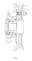
- FIG. 1 is a sectional view for illustrating a bearing unit H according to the embodiment of the present invention.
- FIG. 2 is a sectional view for illustrating a vicinity of a fitting bolt in the bearing unit H shown in FIG. 1 .
- the bearing unit H shown in FIG. 1 and FIG. 2 has the same basic structure as that of the bearing unit shown in FIG. 3 , and accordingly, the same reference numerals are assigned to constitutional elements of the bearing unit H, which are the same as those shown in FIG. 3 .
- the bearing unit H is a bearing unit for an axle on a drive wheel side in a vehicle.
- the bearing unit H includes an outer ring member 2, an inner ring member 3 and balls 4.
- a flange portion 1, which is fitted to a vehicle body side, is formed on an outer periphery of the outer ring member 2.
- the inner ring member 3 is rotatably inserted in the outer ring member 2.
- the balls 4 are rolling elements in double rows, which are rollably arranged between the outer ring member 2 and inner ring member 3.
- the outer ring member 2 has outer ring raceway surfaces 2a in double rows formed in an inner peripheral surface thereof.
- the inner ring member 3 has inner ring raceway surfaces 3a that are formed in an outer peripheral surface thereof and opposed to the outer ring raceway surfaces 2a.
- the balls 4 are arranged between the outer ring raceway surfaces 2a and the inner ring raceway surfaces 3a.
- the inner ring member 3 includes a hub spindle 5 and an inner ring component member 6 that is a member separate from the hub spindle 5, and that is fitted to an outer periphery of a vehicle inner side end portion (left side end portion in FIG. 1 ) of the hub spindle 5.
- the hub spindle 5 is rotatably supported by the outer ring member 2 through the balls 4 in double rows.
- the balls 4 are retained at predetermined circumferential intervals on the inner ring raceway surfaces 3a by a cage 20. Opposite end portions of an annular space defined between the inner ring member 3 and the outer ring member 2 are hermetically sealed by seal members 21.
- a wheel fitting flange 7 for fitting a wheel to the bearing unit H is formed on an outer periphery of a vehicle outer side end portion of the hub spindle 5.
- Bolt holes 8 are formed at predetermined intervals in a peripheral edge portion of the wheel fitting flange 7.
- a wheel 10 and a brake rotor 11, which are wheel side component parts, are fitted to fitting bolts 9 that are press-fitted in the bolt holes 8.
- the wheel 10 and the brake rotor 11 are fastened together by nuts 13.
- each of the fitting bolts 9 has an engagement portion 9b in the vicinity of a head 9a thereof, and the engagement portion 9b is formed so as to have a diameter larger than that of each of the bolt holes 8.
- the engagement portion 9b is caught into an inner peripheral surface of this bolt hole 8, and thus, it is possible to prevent the fitting bolt 9 from being rotated together with the corresponding nut 13 when the nut 13 is tightened.
- the recessed portion may be a circumferential groove 22 whose bottom portion has an arc-shaped section (in a plane containing the rotation axis of the bearing unit H). Further, the recessed portion may be a circumferential groove that has a section in another shape, for example, a circumferential groove that has a rectangular section or V-shaped section. Although a depth d of the circumferential groove 22 is not particularly limited, the depth d may be set to, for example, 1 to 2 mm.
- the recessed portion may be formed over the entire outer peripheral surface of the wheel fitting flange 7, like the circumferential groove 22 in the embodiment. However, the recessed portion may be formed only in a portion outside each of the bolt holes 8 in a radial direction of the wheel fitting flange 7, in the outer peripheral surface of the wheel fitting flange 7.
- the recessed portion is formed in the outer peripheral surface of the wheel fitting flange 7 having the peripheral edge portion that has the bolt holes 8 into which the fitting bolts 9 are press-fitted, a portion outside each of the bolt holes 8 can be made thin.
- a ridge of material that is, deformation of the material in a portion around each of the bolt holes 8, which is caused by press-fitting the corresponding fitting bolt 9 in the bolt hole 8 with a predetermined interference (for example, approximately 0.1 to 0.5 mm)
- a predetermined interference for example, approximately 0.1 to 0.5 mm
- the balls are used as rolling elements in the above-mentioned embodiment, tapered rollers may be used as rolling elements.
- the bearing unit is used for the axle on the drive wheel side in the vehicle in the above-mentioned embodiment, the present invention may be applied to a bearing unit for an axle on a driven wheel side.
Landscapes
- Engineering & Computer Science (AREA)
- Mechanical Engineering (AREA)
- Rolling Contact Bearings (AREA)
Abstract
Description
- The invention relates to a bearing unit, and in particular to a bearing unit in which a wheel fitting flange is formed on an outer periphery of an inner ring member.
- Conventionally, various kinds of bearing units for supporting a wheel of a vehicle with respect to a suspension in a vehicle body so that the wheel is rotatable have been proposed. For example, as shown in
FIG. 3 , such a bearing unit includes anouter ring member 2, aninner ring member 3 andballs 4. A flange portion 1, which is fitted to a vehicle body side, is formed on an outer periphery of theouter ring member 2. Theinner ring member 3 is rotatably inserted in theouter ring member 2. Theballs 4 are rolling elements in double rows, which are rollably arranged between theouter ring member 2 and theinner ring member 3. The bearing unit shown inFIG. 3 is a bearing unit for an axle on a drive wheel side of a vehicle. Theinner ring member 3 includes ahub spindle 5 and an innerring component member 6 that is a member separate from thehub spindle 5. The innerring component member 6 is fitted to an outer periphery of a vehicle inner side end portion (left side end portion inFIG. 3 ) of thehub spindle 5. Awheel fitting flange 7 for fitting a wheel to the bearing unit is formed on an outer periphery of a vehicle outer side end portion of thehub spindle 5.Bolt holes 8 are formed at predetermined intervals in a peripheral edge portion of thewheel fitting flange 7. Awheel 10 and abrake rotor 11, which are vehicle side component parts, are fitted to fittingbolts 9 that are press-fitted in thebolt holes 8. Thewheel 10 and thebrake rotor 11 are fastened together bynuts 13. - The
brake rotor 11 is combined with a brake system that brakes the rotation of thewheel 10 so as to decelerate the running vehicle. The brake system brakes the rotation of thewheel 10 by pressing brake shoes (not shown), which are secured to the vehicle body side, to thebrake rotor 11 so that frictional force is generated. In this case, in order to uniformly generate the frictional force during braking so as to allow the brake system to appropriately exhibit its performance, it is necessary to make clearances between thebrake rotor 11 and the brake shoes uniform. For example, if the clearances are not uniform, the frictional force varies during one revolution of thebrake rotor 11, and such variation is transmitted in the form of vibration, to thewheel 10 and the vehicle body. As a result, the phenomenon called brake judder occurs. - The braking judder not only causes the occupants to feel discomfort, but also lowers the braking performance and adversely affects the drivability of the vehicle. Thus, in order to suppress the braking judder, it has been demanded to improve the runout accuracy of the
brake rotor 11 after thebrake rotor 11 is installed in the vehicle. - As a measure for improving the runout accuracy of the
brake rotor 11, it may be considered to improve the accuracy of thebrake rotor 11 itself. In addition to the above-mentioned measure, there have been measures that are focused on an improvement in flatness of thewheel fitting flange 7 having a surface to which thebrake rotor 11 is fitted. - The
fitting bolts 9 are fitted in thebolt holes 8 by interference fit, and an interference is set to approximately 0.1 to 0.5 mm (the interference varies depending upon specifications of the bearing unit). Thus, press-fitting of thefitting bolts 9 into thebolt holes 8 may deteriorate the degree of flatness of the surface of the wheel fittingflange 7. Specifically, by press-fitting thefitting bolts 9 in thebolt holes 8, a bulgingportion 12 may be formed on asurface 7a of thewheel fitting flange 7 on a side opposite to a surface on which heads 9a of thefitting bolts 9 abut, as exaggeratedly shown inFIG. 4 . A bulging height of the bulgingportion 12 may reach a value in a range from 25 to 30 µm. As a result, when thebrake rotor 11 is fitted, a fitted surface of thebrake rotor 11 abuts on the bulgingportion 12, and accordingly, the runout accuracy of thebrake rotor 11 is lowered. Moreover, as exaggeratedly shown by a long dashed double-short dashed line inFIG. 4 , an outer peripheral edge of thewheel fitting flange 7 may be deformed (warped) toward the above-mentioned fitted surface (toward the wheel). In the case where such deformation occurs in thewheel fitting flange 7 as well, since the fitted surface of thebrake rotor 11 abuts on adeformed portion 14 that is deformed as described above, when thebrake rotor 11 is fitted, the runout accuracy of thebrake rotor 11 is lowered. - In order to suppress the lowering of the runout accuracy of the
brake rotor 11 caused by the bulgingportion 12 and thedeformed portion 14 as described above, it has been proposed to remove the bulgingportion 12 and thedeformed portion 14 by performing a turning process. However, the turning process is laborious, and accordingly, the cost for the tuning process is caused. As a result, the cost for producing the bearing unit is increased. Further, a problem regarding the quality of the bearing unit may be caused due to adhesion of chips or the like. - Thus, a method for preventing deformation of the
wheel fitting flange 7 without the necessity of machining thewheel fitting flange 7 after the fittingbolts 9 are press-fitted has been proposed (refer to, for example, Japanese Patent Application Publication2007-232169 JP 2007-232169 A JP 2007-232169 A - However, in the method described in
JP 2007-232169 A FIG. 1 to FIG. 3 inJP 2007-232169 JP 2007-232169 A - An object of the present invention is to provide a bearing unit in which deformation of a wheel fitting flange is suppressed during press-fitting of bolts, by using simple machining, and at low cost.
- According to an aspect of the preset invention, there is provided a bearing unit including: an outer ring member having an outer periphery on which a flange portion is formed, the flange portion being fitted to a vehicle body side; an inner ring member that is rotatably inserted in the outer ring member; and rolling elements in double rows, which are rollably arranged between the outer ring member and the inner ring member, wherein bolts are press-fitted in bolt holes formed in a peripheral edge portion of a wheel fitting flange that is formed on an outer periphery of the inner ring member, and a recessed portion is formed in an outer peripheral surface of the wheel fitting flange.
- The foregoing and further features, and advantages of the invention will become apparent from the following description of example embodiments with reference to the accompanying drawings, wherein like numerals are used to represent like elements and wherein:
-
FIG. 1 is a sectional view for illustrating a bearing unit according to an embodiment of the present invention; -
FIG. 2 is a sectional view for illustrating a vicinity of a fitting bolt in the bearing unit shown inFIG. 1 ; -
FIG. 3 is a sectional view for illustrating a bearing unit in related art; and -
FIG. 4 is a schematic view illustrating a part in which a bolt is press-fitted in the bearing unit in the related art. - Detailed description will be hereinafter made as to a bearing unit according to an embodiment of the present invention with reference to the accompanying drawings.
FIG. 1 is a sectional view for illustrating a bearing unit H according to the embodiment of the present invention.FIG. 2 is a sectional view for illustrating a vicinity of a fitting bolt in the bearing unit H shown inFIG. 1 . It is to be noted that the bearing unit H shown inFIG. 1 andFIG. 2 has the same basic structure as that of the bearing unit shown inFIG. 3 , and accordingly, the same reference numerals are assigned to constitutional elements of the bearing unit H, which are the same as those shown inFIG. 3 . - The bearing unit H is a bearing unit for an axle on a drive wheel side in a vehicle. The bearing unit H includes an
outer ring member 2, aninner ring member 3 andballs 4. A flange portion 1, which is fitted to a vehicle body side, is formed on an outer periphery of theouter ring member 2. Theinner ring member 3 is rotatably inserted in theouter ring member 2. Theballs 4 are rolling elements in double rows, which are rollably arranged between theouter ring member 2 andinner ring member 3. - The
outer ring member 2 has outerring raceway surfaces 2a in double rows formed in an inner peripheral surface thereof. Theinner ring member 3 has innerring raceway surfaces 3a that are formed in an outer peripheral surface thereof and opposed to the outerring raceway surfaces 2a. Theballs 4 are arranged between the outerring raceway surfaces 2a and the innerring raceway surfaces 3a. - The
inner ring member 3 includes ahub spindle 5 and an innerring component member 6 that is a member separate from thehub spindle 5, and that is fitted to an outer periphery of a vehicle inner side end portion (left side end portion inFIG. 1 ) of thehub spindle 5. Thehub spindle 5 is rotatably supported by theouter ring member 2 through theballs 4 in double rows. - The
balls 4 are retained at predetermined circumferential intervals on the inner ring raceway surfaces 3a by acage 20. Opposite end portions of an annular space defined between theinner ring member 3 and theouter ring member 2 are hermetically sealed byseal members 21. - A wheel
fitting flange 7 for fitting a wheel to the bearing unit H is formed on an outer periphery of a vehicle outer side end portion of thehub spindle 5. Bolt holes 8 are formed at predetermined intervals in a peripheral edge portion of the wheelfitting flange 7. Awheel 10 and abrake rotor 11, which are wheel side component parts, are fitted tofitting bolts 9 that are press-fitted in the bolt holes 8. Thewheel 10 and thebrake rotor 11 are fastened together by nuts 13. Further, each of thefitting bolts 9 has anengagement portion 9b in the vicinity of ahead 9a thereof, and theengagement portion 9b is formed so as to have a diameter larger than that of each of the bolt holes 8. Accordingly, when thefitting bolt 9 is press-fitted in thecorresponding bolt hole 8, theengagement portion 9b is caught into an inner peripheral surface of thisbolt hole 8, and thus, it is possible to prevent thefitting bolt 9 from being rotated together with the correspondingnut 13 when thenut 13 is tightened. - The feature of the present invention is that a recessed portion is formed in an outer peripheral surface of the wheel
fitting flange 7. As shown inFIG. 2 , the recessed portion may be acircumferential groove 22 whose bottom portion has an arc-shaped section (in a plane containing the rotation axis of the bearing unit H). Further, the recessed portion may be a circumferential groove that has a section in another shape, for example, a circumferential groove that has a rectangular section or V-shaped section. Although a depth d of thecircumferential groove 22 is not particularly limited, the depth d may be set to, for example, 1 to 2 mm. The recessed portion may be formed over the entire outer peripheral surface of the wheelfitting flange 7, like thecircumferential groove 22 in the embodiment. However, the recessed portion may be formed only in a portion outside each of the bolt holes 8 in a radial direction of the wheelfitting flange 7, in the outer peripheral surface of the wheelfitting flange 7. - Since the recessed portion is formed in the outer peripheral surface of the wheel
fitting flange 7 having the peripheral edge portion that has the bolt holes 8 into which thefitting bolts 9 are press-fitted, a portion outside each of the bolt holes 8 can be made thin. Thus, a ridge of material, that is, deformation of the material in a portion around each of the bolt holes 8, which is caused by press-fitting the correspondingfitting bolt 9 in thebolt hole 8 with a predetermined interference (for example, approximately 0.1 to 0.5 mm), can be absorbed by the thin portion. Thus, it is possible to suppress the formation of the above-mentioned bulgingportion 12 or occurrence of deformation due to the press-fitting of the bolt. The recessed portion in the outer peripheral surface of the wheelfitting flange 7 can be formed more easily than the recesses inJP 2007-23169 A - It is to be noted that the described embodiment is to be considered in all respects only as illustrative and not restrictive. The scope of the present invention should not be limited by the above-mentioned embodiment, and should be defined by the appended claims. All changes that come within the meaning and range of equivalency of the claims are to be embraced within the scope.
- For example, although the balls are used as rolling elements in the above-mentioned embodiment, tapered rollers may be used as rolling elements. Further, although the bearing unit is used for the axle on the drive wheel side in the vehicle in the above-mentioned embodiment, the present invention may be applied to a bearing unit for an axle on a driven wheel side.
- With the bearing unit according to the present invention, it is possible to suppress deformation of the wheel fitting flange during press-fitting of the fitting bolts, by using simple machining, and at low cost.
Claims (2)
- A bearing unit comprising:an outer ring member having an outer periphery on which a flange portion is formed, the flange portion being fitted to a vehicle body side;an inner ring member that is rotatably inserted in the outer ring member; androlling elements in double rows, which are rollably arranged between the outer ring member and the inner ring member, whereinbolts are press-fitted in bolt holes formed in a peripheral edge portion of a wheel fitting flange that is formed on an outer periphery of the inner ring member, anda recessed portion is formed in an outer peripheral surface of the wheel fitting flange.
- The bearing unit according to claim 1, wherein the recessed portion is formed only in a portion outside each of the bolt holes in a radial direction of the wheel fitting flange, in the outer peripheral surface of the wheel fitting flange.
Applications Claiming Priority (1)
| Application Number | Priority Date | Filing Date | Title |
|---|---|---|---|
| JP2012187574A JP2014043201A (en) | 2012-08-28 | 2012-08-28 | Bearing unit |
Publications (1)
| Publication Number | Publication Date |
|---|---|
| EP2703184A1 true EP2703184A1 (en) | 2014-03-05 |
Family
ID=49033919
Family Applications (1)
| Application Number | Title | Priority Date | Filing Date |
|---|---|---|---|
| EP13181650.6A Withdrawn EP2703184A1 (en) | 2012-08-28 | 2013-08-26 | Bearing unit |
Country Status (4)
| Country | Link |
|---|---|
| US (1) | US8814435B2 (en) |
| EP (1) | EP2703184A1 (en) |
| JP (1) | JP2014043201A (en) |
| CN (1) | CN103671497A (en) |
Citations (4)
| Publication number | Priority date | Publication date | Assignee | Title |
|---|---|---|---|---|
| EP1110756A2 (en) * | 1999-12-16 | 2001-06-27 | Nsk Ltd | Wheel-support rolling bearing unit and a method manufacturing the same |
| JP2003094905A (en) * | 2001-09-26 | 2003-04-03 | Koyo Seiko Co Ltd | Bearing device for axle |
| JP2007023169A (en) | 2005-07-15 | 2007-02-01 | Fujifilm Holdings Corp | Method for producing organic pigment particle |
| JP2007232169A (en) | 2006-03-03 | 2007-09-13 | Nsk Ltd | Bearing unit |
Family Cites Families (11)
| Publication number | Priority date | Publication date | Assignee | Title |
|---|---|---|---|---|
| JPS58191607A (en) * | 1982-03-29 | 1983-11-08 | エス・ケイ・エフ・ノ−バ・エ−ビ− | Hub bearing unit |
| JP4299957B2 (en) * | 2000-07-17 | 2009-07-22 | 株式会社ジェイテクト | Manufacturing method of bearing device |
| JP4062868B2 (en) * | 2000-07-31 | 2008-03-19 | 株式会社ジェイテクト | Axle bearing device |
| DE102004044118B4 (en) * | 2004-09-11 | 2013-09-12 | Schaeffler Technologies AG & Co. KG | Wheel bearing arrangement with a radial flange side encoder |
| JP2008074332A (en) * | 2006-09-25 | 2008-04-03 | Jtekt Corp | Rolling bearing device for wheels |
| CN201382084Y (en) * | 2008-11-24 | 2010-01-13 | 新昌县开源汽车轴承有限公司 | Automobile wheel hub bearing unit |
| CN201297340Y (en) * | 2008-11-30 | 2009-08-26 | 湖北新火炬科技股份有限公司 | Screw riveting ABS sensor car hub bearing unit assembly |
| CN101804770B (en) * | 2009-02-17 | 2015-03-04 | 株式会社捷太格特 | Wheel bearing device and manufacturing method therefor |
| CN201621189U (en) * | 2010-01-29 | 2010-11-03 | 浙江凯迪汽车部件工业有限公司 | Hub bearing unit with ABS sensor |
| CN102135134B (en) * | 2011-03-25 | 2013-06-19 | 浙江兆丰机电股份有限公司 | Automobile hub bearing unit |
| CN202023836U (en) * | 2011-04-20 | 2011-11-02 | 杭州沃众汽车轴承有限公司 | Hub bearing unit with hemming structure having inconsistent double channels |
-
2012
- 2012-08-28 JP JP2012187574A patent/JP2014043201A/en active Pending
-
2013
- 2013-08-06 US US13/960,278 patent/US8814435B2/en not_active Expired - Fee Related
- 2013-08-07 CN CN201310341858.XA patent/CN103671497A/en active Pending
- 2013-08-26 EP EP13181650.6A patent/EP2703184A1/en not_active Withdrawn
Patent Citations (4)
| Publication number | Priority date | Publication date | Assignee | Title |
|---|---|---|---|---|
| EP1110756A2 (en) * | 1999-12-16 | 2001-06-27 | Nsk Ltd | Wheel-support rolling bearing unit and a method manufacturing the same |
| JP2003094905A (en) * | 2001-09-26 | 2003-04-03 | Koyo Seiko Co Ltd | Bearing device for axle |
| JP2007023169A (en) | 2005-07-15 | 2007-02-01 | Fujifilm Holdings Corp | Method for producing organic pigment particle |
| JP2007232169A (en) | 2006-03-03 | 2007-09-13 | Nsk Ltd | Bearing unit |
Also Published As
| Publication number | Publication date |
|---|---|
| JP2014043201A (en) | 2014-03-13 |
| US20140064647A1 (en) | 2014-03-06 |
| US8814435B2 (en) | 2014-08-26 |
| CN103671497A (en) | 2014-03-26 |
Similar Documents
| Publication | Publication Date | Title |
|---|---|---|
| US6250814B1 (en) | Automotive wheel bearing assembly and method for manufacturing the same | |
| US10207537B2 (en) | Method for manufacturing hub ring and method for manufacturing vehicle bearing apparatus | |
| JP2009008165A (en) | Wheel bearing device | |
| EP3546777B1 (en) | Hub unit bearing, method for manufacturing same, motor vehicle, and method for manufacturing same | |
| CN101516639B (en) | Hub wheel, hub unit, and method of working hub wheel | |
| JP2010089664A (en) | Bearing device for wheel | |
| EP2497583B1 (en) | Method of manufacturing a shaft member for a wheel hub assembly with rolling bearings | |
| JP5030187B2 (en) | Grease filling method for wheel bearing device | |
| US8814435B2 (en) | Bearing unit | |
| JP2008173995A (en) | Bearing device for wheel | |
| JP2005140192A (en) | Bearing device for wheel | |
| JP5030082B2 (en) | Wheel bearing device | |
| US10486463B2 (en) | Hub unit bearing | |
| JP4844967B2 (en) | Wheel bearing device | |
| JP2007223520A (en) | Method of manufacturing bearing device for wheel | |
| JP4647333B2 (en) | Cutting method of braking surface of wheel bearing device with brake rotor | |
| JP2006007910A (en) | Bearing device for wheel | |
| JP7701776B2 (en) | Wheel bearing device and method for manufacturing the wheel bearing device | |
| JP2005337311A (en) | Bearing device for wheel | |
| JP2005289147A (en) | Bearing device for wheel | |
| JP2005335455A (en) | Bearing device for wheel | |
| JP2005297878A (en) | Bearing device for vehicle wheel with brake rotor | |
| JP2005306290A (en) | Bearing equipment for wheel with brake rotor | |
| JP2006007820A (en) | Rolling bearings for wheels | |
| JP2007223563A (en) | Bearing device for wheel |
Legal Events
| Date | Code | Title | Description |
|---|---|---|---|
| AK | Designated contracting states |
Kind code of ref document: A1 Designated state(s): AL AT BE BG CH CY CZ DE DK EE ES FI FR GB GR HR HU IE IS IT LI LT LU LV MC MK MT NL NO PL PT RO RS SE SI SK SM TR |
|
| AX | Request for extension of the european patent |
Extension state: BA ME |
|
| PUAI | Public reference made under article 153(3) epc to a published international application that has entered the european phase |
Free format text: ORIGINAL CODE: 0009012 |
|
| 17P | Request for examination filed |
Effective date: 20140904 |
|
| RBV | Designated contracting states (corrected) |
Designated state(s): AL AT BE BG CH CY CZ DE DK EE ES FI FR GB GR HR HU IE IS IT LI LT LU LV MC MK MT NL NO PL PT RO RS SE SI SK SM TR |
|
| STAA | Information on the status of an ep patent application or granted ep patent |
Free format text: STATUS: THE APPLICATION HAS BEEN WITHDRAWN |
|
| 18W | Application withdrawn |
Effective date: 20160224 |