EP2703164A2 - Inkjet head - Google Patents
Inkjet head Download PDFInfo
- Publication number
- EP2703164A2 EP2703164A2 EP13180150.8A EP13180150A EP2703164A2 EP 2703164 A2 EP2703164 A2 EP 2703164A2 EP 13180150 A EP13180150 A EP 13180150A EP 2703164 A2 EP2703164 A2 EP 2703164A2
- Authority
- EP
- European Patent Office
- Prior art keywords
- nozzle plate
- air groove
- inkjet head
- partition wall
- face
- Prior art date
- Legal status (The legal status is an assumption and is not a legal conclusion. Google has not performed a legal analysis and makes no representation as to the accuracy of the status listed.)
- Granted
Links
- 238000005192 partition Methods 0.000 claims abstract description 90
- 239000000853 adhesive Substances 0.000 claims abstract description 29
- 230000001070 adhesive effect Effects 0.000 claims abstract description 29
- 239000000463 material Substances 0.000 claims abstract description 25
- 238000007599 discharging Methods 0.000 claims abstract description 3
- 239000007788 liquid Substances 0.000 claims description 27
- 239000011521 glass Substances 0.000 claims description 10
- 229910052751 metal Inorganic materials 0.000 claims description 10
- 239000002184 metal Substances 0.000 claims description 10
- 239000000758 substrate Substances 0.000 description 26
- 230000003139 buffering effect Effects 0.000 description 6
- 230000000052 comparative effect Effects 0.000 description 5
- 238000005530 etching Methods 0.000 description 5
- 238000000034 method Methods 0.000 description 5
- 229920003002 synthetic resin Polymers 0.000 description 5
- 239000000057 synthetic resin Substances 0.000 description 5
- 238000004519 manufacturing process Methods 0.000 description 4
- 238000005516 engineering process Methods 0.000 description 3
- 239000004593 Epoxy Substances 0.000 description 2
- 239000004642 Polyimide Substances 0.000 description 2
- 239000000872 buffer Substances 0.000 description 2
- 239000012141 concentrate Substances 0.000 description 2
- 230000000694 effects Effects 0.000 description 2
- 150000002739 metals Chemical class 0.000 description 2
- 230000010287 polarization Effects 0.000 description 2
- 229920001721 polyimide Polymers 0.000 description 2
- 229910000531 Co alloy Inorganic materials 0.000 description 1
- 229910000990 Ni alloy Inorganic materials 0.000 description 1
- -1 Ni or Cu Chemical class 0.000 description 1
- 230000006399 behavior Effects 0.000 description 1
- 239000007795 chemical reaction product Substances 0.000 description 1
- 229910052802 copper Inorganic materials 0.000 description 1
- 230000032798 delamination Effects 0.000 description 1
- 238000005323 electroforming Methods 0.000 description 1
- 238000011156 evaluation Methods 0.000 description 1
- 238000003384 imaging method Methods 0.000 description 1
- 230000005499 meniscus Effects 0.000 description 1
- 230000007935 neutral effect Effects 0.000 description 1
- 229910052759 nickel Inorganic materials 0.000 description 1
- 238000003672 processing method Methods 0.000 description 1
- 230000000644 propagated effect Effects 0.000 description 1
- 230000003014 reinforcing effect Effects 0.000 description 1
- 238000005488 sandblasting Methods 0.000 description 1
- 239000004065 semiconductor Substances 0.000 description 1
- 229910052710 silicon Inorganic materials 0.000 description 1
Images


Classifications
-
- B—PERFORMING OPERATIONS; TRANSPORTING
- B41—PRINTING; LINING MACHINES; TYPEWRITERS; STAMPS
- B41J—TYPEWRITERS; SELECTIVE PRINTING MECHANISMS, i.e. MECHANISMS PRINTING OTHERWISE THAN FROM A FORME; CORRECTION OF TYPOGRAPHICAL ERRORS
- B41J2/00—Typewriters or selective printing mechanisms characterised by the printing or marking process for which they are designed
- B41J2/005—Typewriters or selective printing mechanisms characterised by the printing or marking process for which they are designed characterised by bringing liquid or particles selectively into contact with a printing material
- B41J2/01—Ink jet
- B41J2/135—Nozzles
- B41J2/14—Structure thereof only for on-demand ink jet heads
- B41J2/14201—Structure of print heads with piezoelectric elements
- B41J2/14209—Structure of print heads with piezoelectric elements of finger type, chamber walls consisting integrally of piezoelectric material
-
- B—PERFORMING OPERATIONS; TRANSPORTING
- B41—PRINTING; LINING MACHINES; TYPEWRITERS; STAMPS
- B41J—TYPEWRITERS; SELECTIVE PRINTING MECHANISMS, i.e. MECHANISMS PRINTING OTHERWISE THAN FROM A FORME; CORRECTION OF TYPOGRAPHICAL ERRORS
- B41J2/00—Typewriters or selective printing mechanisms characterised by the printing or marking process for which they are designed
- B41J2/005—Typewriters or selective printing mechanisms characterised by the printing or marking process for which they are designed characterised by bringing liquid or particles selectively into contact with a printing material
- B41J2/01—Ink jet
- B41J2/135—Nozzles
- B41J2/14—Structure thereof only for on-demand ink jet heads
- B41J2/1433—Structure of nozzle plates
-
- B—PERFORMING OPERATIONS; TRANSPORTING
- B41—PRINTING; LINING MACHINES; TYPEWRITERS; STAMPS
- B41J—TYPEWRITERS; SELECTIVE PRINTING MECHANISMS, i.e. MECHANISMS PRINTING OTHERWISE THAN FROM A FORME; CORRECTION OF TYPOGRAPHICAL ERRORS
- B41J2/00—Typewriters or selective printing mechanisms characterised by the printing or marking process for which they are designed
- B41J2/005—Typewriters or selective printing mechanisms characterised by the printing or marking process for which they are designed characterised by bringing liquid or particles selectively into contact with a printing material
- B41J2/01—Ink jet
- B41J2/135—Nozzles
- B41J2/16—Production of nozzles
- B41J2/1607—Production of print heads with piezoelectric elements
- B41J2/1609—Production of print heads with piezoelectric elements of finger type, chamber walls consisting integrally of piezoelectric material
-
- B—PERFORMING OPERATIONS; TRANSPORTING
- B41—PRINTING; LINING MACHINES; TYPEWRITERS; STAMPS
- B41J—TYPEWRITERS; SELECTIVE PRINTING MECHANISMS, i.e. MECHANISMS PRINTING OTHERWISE THAN FROM A FORME; CORRECTION OF TYPOGRAPHICAL ERRORS
- B41J2/00—Typewriters or selective printing mechanisms characterised by the printing or marking process for which they are designed
- B41J2/005—Typewriters or selective printing mechanisms characterised by the printing or marking process for which they are designed characterised by bringing liquid or particles selectively into contact with a printing material
- B41J2/01—Ink jet
- B41J2/135—Nozzles
- B41J2/16—Production of nozzles
- B41J2/1621—Manufacturing processes
- B41J2/1623—Manufacturing processes bonding and adhesion
-
- B—PERFORMING OPERATIONS; TRANSPORTING
- B41—PRINTING; LINING MACHINES; TYPEWRITERS; STAMPS
- B41J—TYPEWRITERS; SELECTIVE PRINTING MECHANISMS, i.e. MECHANISMS PRINTING OTHERWISE THAN FROM A FORME; CORRECTION OF TYPOGRAPHICAL ERRORS
- B41J2/00—Typewriters or selective printing mechanisms characterised by the printing or marking process for which they are designed
- B41J2/005—Typewriters or selective printing mechanisms characterised by the printing or marking process for which they are designed characterised by bringing liquid or particles selectively into contact with a printing material
- B41J2/01—Ink jet
- B41J2/135—Nozzles
- B41J2/16—Production of nozzles
- B41J2/1621—Manufacturing processes
- B41J2/1626—Manufacturing processes etching
-
- B—PERFORMING OPERATIONS; TRANSPORTING
- B41—PRINTING; LINING MACHINES; TYPEWRITERS; STAMPS
- B41J—TYPEWRITERS; SELECTIVE PRINTING MECHANISMS, i.e. MECHANISMS PRINTING OTHERWISE THAN FROM A FORME; CORRECTION OF TYPOGRAPHICAL ERRORS
- B41J2/00—Typewriters or selective printing mechanisms characterised by the printing or marking process for which they are designed
- B41J2/005—Typewriters or selective printing mechanisms characterised by the printing or marking process for which they are designed characterised by bringing liquid or particles selectively into contact with a printing material
- B41J2/01—Ink jet
- B41J2/135—Nozzles
- B41J2/16—Production of nozzles
- B41J2/1621—Manufacturing processes
- B41J2/1632—Manufacturing processes machining
Definitions
- the present invention relates to an inkjet head, and more particularly to a shear mode type inkjet head in which channels and end faces of partition walls made of a piezoelectric material are alternately aligned on a front end face of a head chip and a nozzle plate is joined to the front end face of this head chip.
- the inkjet head there is known a shear mode type inkjet head that has channels and partition walls made of a piezoelectric material alternately aligned, deforms the partition walls into a V-like shape based on a drive voltage when the drive voltage is applied to electrodes formed on partition wall surfaces facing the inside of the channels, and thereby discharges an ink in the channels from nozzles, and the present inventor has focused on a deforming operation of the partition walls at the time of discharge and examined a factor that inhibits the smooth deforming operation in order to enable faster stable drive in such a shear mode type inkjet head.
- each channel 101 is opened in a front end face 100a of a head chip 100, and openings 101a of the channels 101 and front end faces 102a of partition walls 102 are alternately aligned when the head chip 100 is observed from the front end face 100a.
- a nozzle plate 200 having nozzles 201 formed at positions associated with the channels 101 is joined to the front end face 100a of this head chip 100 through an adhesive 300.
- FIG. 12 is a view showing the head chip 100 depicted in FIG. 11 from the front end face 100a side.
- a predetermined drive voltage is applied to electrodes (not shown) formed on both surfaces of each partition wall 102
- each partition wall 102 deforms into a V-like shape as indicated by a solid line from a neutral state indicated by a broken line based on the drive voltage, whereby a pressure required for discharge from each nozzle 201 is given to an ink in each channel 101. Since this deforming operation of each partition wall 102 is actually carried out in very short time, it can be regarded as vibration of each partition wall 102.
- each partition wall 102 joined to the nozzle plate 200 since the front end surface 102a side of each partition wall 102 joined to the nozzle plate 200 is completely secured to the nozzle plate 200 through the adhesive 300 in order to prevent the ink from leaking between the channels 101, vibration energy at the time of the deforming operation of each partition wall 102 concentrates on this secured region. Since the vibration energy concentrating on this secured region is trapped, it is inverted and propagated from the front end face 102a toward a central portion of each partition wall 102, and this energy affects the deforming operation when the same partition wall 102 performs the subsequent deforming operation. As a result, there arises a problem that the smooth deforming operation of each partition wall 102 is inhibited, a drop speed is lowered, and stable drive is difficult at the time of performing high-frequency drive in particular.
- any material causes the above-described problem in no small measure as long as the nozzle plate is bonded to the front end face of each partition wall to secure this front end face, but the vibration energy concentrating on the front end face of each partition wall is hardly buffered as hardness of the nozzle plate material rises, and hence the problem becomes particularly prominent in case of the nozzle plate made of metal, Si, or glass as compared with the nozzle plate made of a synthetic resin.
- the present inventor has examined processing the nozzle plate in order to suppress an influence of the vibration energy at the time of the deforming operation concentrating on the front end face of each partition wall bonded to the nozzle plate.
- Patent Literature 1 discloses forming a plurality of pressure fluctuation buffering portions, which are configured to buffer a pressure fluctuation in an ink reservoir and have a small thickness, in an ink discharge surfaces of a nozzle plate.
- Patent Literature 2 discloses forming a slit, which is configured to control deformation of a substrate and avoid delamination of a nozzle plate, in an ink discharge surface of the nozzle plate with a substantially equal depth as the nozzle plate.
- Patent Literature 3 discloses that, in an inkjet head that has a flow path plate, an intermediate plate, and a nozzle plate laminated therein and has one wall surface plated on the opposite surface side of the nozzle plate in a chamber as a pressure generating chamber being formed as a diaphragm that vibrates by drive of a piezoelectric material, an air trap portion that avoids crosstalk is formed between chambers of the respective plates.
- Patent Literatures 1 to 3 do not disclose a shear mode type inkjet head that drives each partition wall made of a piezoelectric material, and they do not disclose technology of processing the nozzle plate in order to suppress an influence of vibration energy during the deforming operation concentrating on the front end face of each partition wall joined to the nozzle plate in the shear mode type inkjet head.
- the present inventor has found out that an influence of vibration energy at the time of a deforming operation concentrating on a front end face of each partition wall can be suppressed by forming air groove portions on a joint face of a nozzle plate relative to the front end face of the partition wall, thereby bringing the present invention to completion.
- an object of the present invention to provide an inkjet head which is of a shear mode type that a front end face of each partition wall made of a piezoelectric material is joined to a nozzle plate, the inkjet head being capable of improving a drop speed and performing stable drive at a high speed by suppressing an influence of vibration energy at the time of a deforming operation concentrating on the front end face of the partition wall.
- An inkjet head comprising: a head chip in which a plurality of channels and a plurality of partition walls at least partially containing piezoelectric material are alternately aligned and which exerts a pressure for discharging an ink in the channels by a deforming operation of the partition walls based on a drive voltage; and a nozzle plate joined to a front end face of the head chip through an adhesive, front end faces of the partition walls facing the nozzle plate through the adhesive, wherein the nozzle plate has air groove portions concaved from a joint surface of the head chip at positions on the joint surface facing front end faces of the partition walls.
- each of the air groove portions is longer than a height dimension of the channels on the front end face of the head chip.
- the inkjet head which is of a shear mode type that a front end face of each partition wall made of a piezoelectric material is joined to a nozzle plate, the inkjet head being capable of improving a drop speed and performing stable drive at a high speed by suppressing an influence of vibration energy at the time of a deforming operation concentrating on the front end face of the partition wall.
- FIG. 1 shows an example of a shear mode type inkjet head, and (a) is a perspective view showing a cross section of a part thereof whilst (b) is a cross-sectional view of the same.
- reference numeral 11 denotes a channel substrate.
- a plurality of channels 12 formed into a narrow groove shape and a plurality of partition walls 13 are alternately aligned.
- a cover substrate 14 is provided on an upper surface of the channel substrate 11 so as to close the upper side of all the channels 12, thereby forming a head chip 10.
- a nozzle plate 20 is joined to a front end face 10a (an end face facing an ink discharge direction in the head chip 10) of the head chip 10 through an adhesive.
- One end of each channel 12 communicates with the outside through a nozzle 21 formed in the nozzle plate 20.
- a surface of the nozzle plate 20 facing a direction along which an ink is discharged from each nozzle 21 is a nozzle surface, and its opposite surface is a joint surface 20a relative to the head chip 10.
- a front end face 13a of each partition wall 13 is arranged to be level with the front end face 10a of the head chip 10. Therefore, the front end face 13a of the each partition wall 13 is opposite to the joint surface 20a of the nozzle plate 20 through the adhesive.
- each channel 12 is gradually narrowed with respect to the channel substrate 11, and it communicates with a common flow path 15 that is opened and formed in the cover substrate 14 and common to the respective channels 12.
- the common flow path 15 is further closed by a plate 16, and the ink is supplied from an ink supply tube 18 into the common flow path 15 and each channel 12 through an ink supply opening 17 formed in the plate 16.
- Each partition wall 13 is made of a piezoelectric material such as PZT that is electromechanical converting means.
- a piezoelectric material such as PZT that is electromechanical converting means.
- both an upper wall portion 131 and a lower wall portion 132 are made of a polarized piezoelectric material, and a polarization direction of the upper wall portion 131 is opposite to that of the lower wall portion 132, but a portion denoted by, e.g., reference numeral 131 alone may be made of the polarized piezoelectric material, and including this portion in at least part of the partition wall 13 can suffice.
- the partition walls 13 and the channels 12 are alternately aligned. Therefore, one partition wall 13 is shared by the channels 12 and 12 provided on both right and left sides thereof.
- a drive electrode (not shown) is formed in each channel 12 from wall surfaces of both the partition walls 13 and 13 to a bottom surface of the channel 12.
- the partition wall 13 deforms into a V-like shape with a joint surface of the upper wall portion 131 and the lower wall portion 132 as a boundary based on this drive voltage.
- Pressure waves are generated in each channel 12 by the deforming operation of this partition wall 13, and a pressure required for discharge from each nozzle 21 is given to an ink in this channel 12.
- FIG. 2 is a view showing the inkjet head 1 from the nozzle surface side
- FIG. 3 is a cross-sectional view taken along a line (iii)-(iii) in FIG. 2 .
- a material that is generally used for a nozzle plate can be used for the nozzle plate 20, and there is, e.g., a synthetic resin, metal, or glass.
- a nozzle plate made of Si, metal, or glass is preferable. Since a nozzle plate made of each of these materials is harder than a nozzle plate made of a synthetic resin, vibration energy concentrating on a secured region of each partition wall 13 and the nozzle plate 20 is apt to be trapped during the deforming operation of the partition wall 13, and the vibration energy concentrating on the secured region greatly affects the subsequent deforming operation of this partition wall 13. Therefore, in the present invention, when the nozzle plate 20 is made of Si, metal, or glass, a later-described vibration energy buffering effect during the deforming operation of the partition wall 13 can be prominently obtained.
- the nozzle plate made of metal Ni, an Ni/Co alloy, Cu, stainless, or the like can be used.
- each nozzle 21, the liquid chamber, the air groove portion, and others can be processed by sandblasting.
- a laser processing method can be mainly adopted.
- nozzle plate 20 made of Si an example using the nozzle plate 20 made of Si is shown. Since the nozzle plate 20 made of Si can be fabricated by using a semiconductor manufacturing process, highly accurate processing is possible, and the nozzle plate 20 with a high accuracy can be easily fabricated.
- Each air groove portion 23 is formed in the nozzle plate 20 at a position facing the front end face 13a of each partition wall 13 on the joint surface 20a relative to the head chip 10 at a predetermined depth from the joint surface 20a.
- Each air groove portion 23 is placed between the channels 12 adjacent to each other so as to be associated with the front end face 13a of each partition wall 13 joined to the nozzle plate 20 through the adhesive 30.
- Each air groove portion 23 is independent from the other air groove portions 23.
- Each air groove portion 23 is formed into a narrow groove shape extending along a height direction (a direction that is parallel to the nozzle surface and orthogonal to an alignment direction of the channels 12, which is an up-and-down direction in FIG. 2 ) of each partition wall 13, but it does not penetrate to the nozzle surface side.
- Each air groove portion 23 is closed by the front end face 10a of the head chip 10 including the front end face 13a of each partition wall 13 through the adhesive 30, whereby an air chamber having air included therein is formed.
- each air groove portion 23 forming the air chamber having the air included therein by joining to the head chip 10 is provided at a region where the front end face 13a of each partition wall 13 on the joint surface 20a of the nozzle plate 20 is joined through the adhesive 30, when the vibration energy at the time of the deforming operation of each partition wall 13 concentrates on the secured region of the front end face 13a of the partition wall 13 and the nozzle plate 20, air included in the air groove portion 23 absorbs and buffers the vibration energy.
- the vibration energy concentrating on the secured region of the front end face 13a of each partition wall 13 and the nozzle plate 20 can be prevented from being reflected toward a central portion of this partition wall 13, and an influence of this partition wall 13 when it deforms for subsequent discharge can be reduced.
- this width must be formed so as to be narrower than a width of each partition wall 13 (a thickness along the alignment direction of the channels 12), and it is not greater than the width of the partition wall 13, but the vibration energy buffering effect may not be possibly sufficiently exercised when the width is extremely narrow, and hence setting this width to 5 ⁇ m or more is preferable.
- a length L of each air groove portion 23 is preferably longer than a height dimension H (a dimension in a direction that is parallel to the nozzle surface and orthogonal to the alignment direction of the channels 12) of each channel 12 on the front end face 10a of the head chip 10.
- H a dimension in a direction that is parallel to the nozzle surface and orthogonal to the alignment direction of the channels 12
- this depth must be shallower than a thickness of the nozzle plate 20, but strength of the nozzle plate 20 can be reduced when each air groove portion 23 is too deeply formed.
- a specific depth differs depending on each nozzle plate material, it is preferable to set this depth to be not greater than 90% of the thickness of the nozzle plate 20 when the nozzle plate 20 is made of Si.
- each liquid chamber 22 that communicates with the nozzle 21 and has a larger diameter than that of the nozzle 21 is formed in the nozzle plate 20 on the joint surface 20a relative to the head chip 10, it is preferable to form the depth of each air groove portion 23 to be equal to or shallower than a depth of this liquid chamber 22 so as to meet the conditions in view of maintaining durability of the nozzle plate 20.
- the liquid chamber 22 is formed into a rectangular shape slightly smaller than an opening shape of he channel 12 in this embodiment, but the liquid chamber 22 can be formed into any specific shape. Moreover, although the liquid chamber 22 is not required in the present invention, providing the liquid chamber 22 is preferable in case of increasing the thickness of the nozzle plate 20 in terms of assuring the depth of the air groove portion 23.
- the air groove portion 23 associated with one partition wall 13 may be constituted of a plurality of air groove portions 23 a divided along the height direction of the partition wall 13.
- adopting one air groove portion 23 as shown in FIG. 2 is preferable.
- the head chip 10 is bonded to the nozzle plate 20 through the adhesive 30. At this time, as partially shown in FIG. 3 , it is preferable to bond these members in a state that the adhesive 30 has partially entered the air groove portion 23. As a result, the excess adhesive 30 can be collected in the air groove portion 23, and the excess adhesive can be prevented from entering each channel 12 or each nozzle 21, and adhesion is also improved.
- the adhesive can enter the air groove portion 23 when the head chip 10 and the nozzle plate 20 are bonded after being heated.
- the air in the air groove portion 23 contracts, whereby part of the adhesive 30 can enter the air groove portion 23.
- a bonding area increases, and improvement in adhesion force can be expected.
- the adhesive 30 only slightly enters from the opening side of the air groove portion 23 as shown in FIG. 3 and the inside of the air groove portion 23 is not entirely filled with the adhesive 30, but an amount of air in the air groove portion 23 is slightly reduced when part of the adhesive 30 enters the air groove portion 23.
- an epoxy-based adhesive generally used as the adhesive 30 has an elastic modulus lower than that of a nozzle plate material (Si, metal, glass) that is preferably used in the present invention, and hence the vibration energy buffering effect of each partition wall 13 is not greatly deteriorated.
- Si substrate 40 (a thickness: 725 ⁇ m) that is sufficiently thicker than the nozzle plate 20 as an end product is prepared, one entire surface of this substrate is coated with a resist mask 50 ( FIG. 5(a) ), and then the resist mask 50 at each region serving as a position for forming each nozzle 21 is removed, thus forming each opening portion 51 ( FIG. 5(b) ).
- each concave portion 41 having a predetermined depth is formed in each opening portion 51 ( FIG. 5(c) ).
- the concave portions 41 each having a depth of 30 ⁇ m was formed.
- a support substrate 60 formed of a glass substrate having a thickness of 200 ⁇ m for reinforcing the Si substrate 40 is attached to the surface where the concave portions 41 are formed from the upper side of the resist mask 50 ( FIG. 5(d) ).
- the Si substrate 40 having the support substrate 60 attached thereto is polished from the opposite surface side of the support substrate 60 until the Si substrate 40 has a thickness of 200 ⁇ m ( FIG. 6(a) ), and then the polished surface of the Si substrate 40 is coated with a resist mask 70 ( FIG. 6(b) ).
- the resist mask 70 at regions as positions where liquid chambers 22 and air groove portions 23 are formed is removed to form respective liquid chamber opening portions 71 and air groove portion opening portions 72 ( FIG. 6(c) ), and then the Si substrate 40 facing the liquid chamber opening portions 71 and the air groove portion opening portions 72 are recessed by performing etching from the surface of the resist mask 70 ( FIG. 6(d) ).
- each air groove portion opening portion 72 has a narrower width and a smaller opening area than each liquid chamber opening portion 71, an etching rate from the air groove portion opening portions 72 is lower, and a depth of each air groove portion 23 is thereby shallower than that of the liquid chamber 22. As a result, each air groove portion 23 shallower than each liquid chamber 22 can be easily formed.
- the Si substrate 40 is diced into a size of the nozzle plate 20, a plurality of nozzle plates 20 are sliced out, and the support substrate 60 and the respective resist masks 50 and 70 are removed, thereby fabricating the nozzle plate 20 having the air groove portions 23 ( FIG. 6(e) ).
- the above-described inkjet head 1 has a conformation that all channels 12 are ink channels from which an ink is discharged and the nozzle 21 and the liquid chamber 22 are provided in accordance with each channel 12, but this inkjet head 1 may be of a so-called independent drive type that ink channels 121 from which the ink is discharged and dummy channels 122 from which the ink is not discharged are alternately arranged.
- this conformation likewise, since each partition wall 13 deforms in order to discharge the ink from each ink channel 121, each air groove portion 23 is formed on the joint surface of the nozzle plate 20 at a position associated with a front end face 13a of each partition wall 13.
- the nozzle 21 and the liquid chamber 22 are not formed at a region associated with each dummy channel 122 in the nozzle plate 20.
- the above-described inkjet head 1 has one channel string, but it may have a plurality of channel strings which are two or more strings as shown in FIG. 8 .
- the inkjet head 1 can be of an independent drive type that the ink channels 121 and the dummy channels 122 are alternately arranged.
- each above-described air groove portion 23 is formed independently from the other air groove portions 23, the air groove portions 23 may be connected to each other as shown in FIG. 9 as long as each air groove portion 23 is formed at a position in the head chip 10 facing the front end face 13a of each partition wall 13.
- FIG. 9(a) shows a conformation that the air groove portions 23 are connected to each other when one channel string is provided
- FIG. 9(b) shows a conformation that the air groove portions 23 are connected to each other when two channel strings are provided.
- a head chip structure and a nozzle plate structure are as follows.
- each air groove portion extending along a height direction of the partition wall was formed in this nozzle plate at a position facing a front end face of each partition wall of the head chip.
- the above-described nozzle plate was bonded to the front end face of the head chip using an epoxy-based adhesive, thereby fabricating the inkjet head.
- an ink was continuously discharged with a drive voltage of 16.6 V and a drive frequency of each of 24.7 kHz and 12.3 kHz, attention was paid to one of nozzles, and a drop speed was obtained from this nozzle, and evaluation was carried out based on the following criteria.
- the drop speed was measured by imaging each discharged ink drop and performing image processing to an ink drop image. Table 1 shows this result.
- Example 1 An ink was discharged in completely the same manner as Example 1 except a length L of each air groove portion 2 was set to 180 ⁇ m which is shorter than a height H of each channel, and a drop speed was evaluated. Table 1 shows this result.
- Example 1 An ink was discharged in completely the same manner as Example 1 except that air groove portions were not formed in a nozzle plate at all, and a drop speed was evaluated. Table 1 shows this result.
- Air groove portions of a nozzle plate were formed in regions that are parallel to a nozzle string direction and associated with outer sides of respective channels as shown in FIG. 10 .
- a depth and width of each air groove portion are the same as those in Example 1, and a length along the nozzle string direction was set to 50 ⁇ m.
- An ink was discharged from this inkjet head under completely the same drive conditions as those of Example 1, and a drop speed was evaluated. Table 1 shows this result.
Abstract
Description
- The present invention relates to an inkjet head, and more particularly to a shear mode type inkjet head in which channels and end faces of partition walls made of a piezoelectric material are alternately aligned on a front end face of a head chip and a nozzle plate is joined to the front end face of this head chip.
- In regard to an inkjet head that discharges microdroplets from nozzles to hit various recording materials so that an inkjet image can be recorded and formed, performance enabling stable drive at a higher speed has been demanded.
- As the inkjet head, there is known a shear mode type inkjet head that has channels and partition walls made of a piezoelectric material alternately aligned, deforms the partition walls into a V-like shape based on a drive voltage when the drive voltage is applied to electrodes formed on partition wall surfaces facing the inside of the channels, and thereby discharges an ink in the channels from nozzles, and the present inventor has focused on a deforming operation of the partition walls at the time of discharge and examined a factor that inhibits the smooth deforming operation in order to enable faster stable drive in such a shear mode type inkjet head.
- In general, in the shear mode type inkjet head having channels and partition walls made of a piezoelectric material alternately aligned, as shown in
FIG. 11 , one end of eachchannel 101 is opened in afront end face 100a of ahead chip 100, andopenings 101a of thechannels 101 and front end faces 102a ofpartition walls 102 are alternately aligned when thehead chip 100 is observed from thefront end face 100a. Anozzle plate 200 havingnozzles 201 formed at positions associated with thechannels 101 is joined to thefront end face 100a of thishead chip 100 through an adhesive 300. -
FIG. 12 is a view showing thehead chip 100 depicted inFIG. 11 from thefront end face 100a side. When a predetermined drive voltage is applied to electrodes (not shown) formed on both surfaces of eachpartition wall 102, eachpartition wall 102 deforms into a V-like shape as indicated by a solid line from a neutral state indicated by a broken line based on the drive voltage, whereby a pressure required for discharge from eachnozzle 201 is given to an ink in eachchannel 101. Since this deforming operation of eachpartition wall 102 is actually carried out in very short time, it can be regarded as vibration of eachpartition wall 102. - Here, since the
front end surface 102a side of eachpartition wall 102 joined to thenozzle plate 200 is completely secured to thenozzle plate 200 through the adhesive 300 in order to prevent the ink from leaking between thechannels 101, vibration energy at the time of the deforming operation of eachpartition wall 102 concentrates on this secured region. Since the vibration energy concentrating on this secured region is trapped, it is inverted and propagated from thefront end face 102a toward a central portion of eachpartition wall 102, and this energy affects the deforming operation when thesame partition wall 102 performs the subsequent deforming operation. As a result, there arises a problem that the smooth deforming operation of eachpartition wall 102 is inhibited, a drop speed is lowered, and stable drive is difficult at the time of performing high-frequency drive in particular. - As nozzle plate materials, besides a synthetic resin such as a polyimide, there are metals such as Ni or Cu, Si, glass, and others, any material causes the above-described problem in no small measure as long as the nozzle plate is bonded to the front end face of each partition wall to secure this front end face, but the vibration energy concentrating on the front end face of each partition wall is hardly buffered as hardness of the nozzle plate material rises, and hence the problem becomes particularly prominent in case of the nozzle plate made of metal, Si, or glass as compared with the nozzle plate made of a synthetic resin.
- Thus, the present inventor has examined processing the nozzle plate in order to suppress an influence of the vibration energy at the time of the deforming operation concentrating on the front end face of each partition wall bonded to the nozzle plate.
- As conventional technology of processing a nozzle plate,
Patent Literature 1 discloses forming a plurality of pressure fluctuation buffering portions, which are configured to buffer a pressure fluctuation in an ink reservoir and have a small thickness, in an ink discharge surfaces of a nozzle plate. - Additionally, Patent Literature 2 discloses forming a slit, which is configured to control deformation of a substrate and avoid delamination of a nozzle plate, in an ink discharge surface of the nozzle plate with a substantially equal depth as the nozzle plate.
- Further, Patent Literature 3 discloses that, in an inkjet head that has a flow path plate, an intermediate plate, and a nozzle plate laminated therein and has one wall surface plated on the opposite surface side of the nozzle plate in a chamber as a pressure generating chamber being formed as a diaphragm that vibrates by drive of a piezoelectric material, an air trap portion that avoids crosstalk is formed between chambers of the respective plates.
- However, the technologies in
Patent Literatures 1 to 3 do not disclose a shear mode type inkjet head that drives each partition wall made of a piezoelectric material, and they do not disclose technology of processing the nozzle plate in order to suppress an influence of vibration energy during the deforming operation concentrating on the front end face of each partition wall joined to the nozzle plate in the shear mode type inkjet head. -
- Patent Document 1:
JP-A-2005-14618 - Patent Document 2:
JP-A-2007-331245 - Patent Document 3:
JP-A-2011-25657 - As a result of keenly examining the above-described problem, the present inventor has found out that an influence of vibration energy at the time of a deforming operation concentrating on a front end face of each partition wall can be suppressed by forming air groove portions on a joint face of a nozzle plate relative to the front end face of the partition wall, thereby bringing the present invention to completion.
- That is, it is an object of the present invention to provide an inkjet head which is of a shear mode type that a front end face of each partition wall made of a piezoelectric material is joined to a nozzle plate, the inkjet head being capable of improving a drop speed and performing stable drive at a high speed by suppressing an influence of vibration energy at the time of a deforming operation concentrating on the front end face of the partition wall.
- Other objects according to the present invention will become apparent based on the following description.
- The above object can be attained by each of the following inventions.
- 1. An inkjet head comprising: a head chip in which a plurality of channels and a plurality of partition walls at least partially containing piezoelectric material are alternately aligned and which exerts a pressure for discharging an ink in the channels by a deforming operation of the partition walls based on a drive voltage; and a nozzle plate joined to a front end face of the head chip through an adhesive, front end faces of the partition walls facing the nozzle plate through the adhesive, wherein the nozzle plate has air groove portions concaved from a joint surface of the head chip at positions on the joint surface facing front end faces of the partition walls.
- 2. The inkjet head according to 1,
wherein the air groove portions are provided along a height direction of the partition walls. - 3. The inkjet head according to claim 2,
wherein each of the air groove portions is longer than a height dimension of the channels on the front end face of the head chip. - 4. The inkjet head according to 1, 2, or 3,
wherein liquid chambers communicating with nozzles and having a larger diameter than the nozzles are concaved on the joint surface of the nozzle plate relative to the head chip, and
a depth of each air groove portion is equal to or shallower than a depth of each liquid chamber. - 5. The inkjet head according to any one of 1 to 4,
wherein the nozzle plate is bonded to the head chip in a state that the adhesive has partially entered the air groove portions. - 6. The inkjet head according to any one of 1 to 5, wherein the nozzle plate is made of Si, metal, or glass.
- According to the present invention, it is possible to provide the inkjet head which is of a shear mode type that a front end face of each partition wall made of a piezoelectric material is joined to a nozzle plate, the inkjet head being capable of improving a drop speed and performing stable drive at a high speed by suppressing an influence of vibration energy at the time of a deforming operation concentrating on the front end face of the partition wall.
-
-
FIG. 1(a) is a perspective view of a shear mode type inkjet head according to the present invention partially showing a cross section thereof, andFIG. 1 (b) is a longitudinal cross-sectional of the same; -
FIG. 2 is a view showing the inkjet head according to the present invention from a nozzle surface; -
FIG. 3 is a partially enlarged view showing a cross section taken along a line (iii)-(iii) inFIG. 2 ; -
FIG. 4 is a view showing another conformation of an air groove portion; -
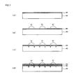
FIGS. 5(a) to (d) are views for explaining an example of a method for manufacturing a nozzle plate of the inkjet head according to the present invention; -
FIGS. 6(a) to (e) are views for explaining an example of the method for manufacturing the nozzle plate of the inkjet head according to the present invention; -
FIG. 7 is a view showing an inkjet head according to another embodiment of the present invention from a nozzle surface; -
FIG. 8 is a view showing an inkjet head according to still another embodiment of the present invention from a nozzle surface; -
FIG. 9 is a view showing an inkjet head according to yet another embodiment of the present invention from a nozzle surface; -
FIG. 10 is a view for explaining a comparative example; -
FIG. 11 is a partial cross-sectional view of a conventional shear mode type inkjet head; and -
FIG. 12 is a view for explaining a deforming operation of each partition wall by using a conventional shear mode type inkjet head. - The present invention will be described below in detail however the present invention is not limited by the description below.
-
FIG. 1 shows an example of a shear mode type inkjet head, and (a) is a perspective view showing a cross section of a part thereof whilst (b) is a cross-sectional view of the same. - In an
inkjet head 1,reference numeral 11 denotes a channel substrate. On thechannel substrate 11, a plurality ofchannels 12 formed into a narrow groove shape and a plurality ofpartition walls 13 are alternately aligned. Acover substrate 14 is provided on an upper surface of thechannel substrate 11 so as to close the upper side of all thechannels 12, thereby forming ahead chip 10. - A
nozzle plate 20 is joined to afront end face 10a (an end face facing an ink discharge direction in the head chip 10) of thehead chip 10 through an adhesive. One end of eachchannel 12 communicates with the outside through anozzle 21 formed in thenozzle plate 20. In thisnozzle plate 20, a surface of thenozzle plate 20 facing a direction along which an ink is discharged from eachnozzle 21 is a nozzle surface, and its opposite surface is ajoint surface 20a relative to thehead chip 10. - A
front end face 13a of eachpartition wall 13 is arranged to be level with thefront end face 10a of thehead chip 10. Therefore, thefront end face 13a of the eachpartition wall 13 is opposite to thejoint surface 20a of thenozzle plate 20 through the adhesive. - The other end of each
channel 12 is gradually narrowed with respect to thechannel substrate 11, and it communicates with acommon flow path 15 that is opened and formed in thecover substrate 14 and common to therespective channels 12. Thecommon flow path 15 is further closed by aplate 16, and the ink is supplied from anink supply tube 18 into thecommon flow path 15 and eachchannel 12 through anink supply opening 17 formed in theplate 16. - Each
partition wall 13 is made of a piezoelectric material such as PZT that is electromechanical converting means. Here, for example, both anupper wall portion 131 and alower wall portion 132 are made of a polarized piezoelectric material, and a polarization direction of theupper wall portion 131 is opposite to that of thelower wall portion 132, but a portion denoted by, e.g.,reference numeral 131 alone may be made of the polarized piezoelectric material, and including this portion in at least part of thepartition wall 13 can suffice. Thepartition walls 13 and thechannels 12 are alternately aligned. Therefore, onepartition wall 13 is shared by thechannels - A drive electrode (not shown) is formed in each
channel 12 from wall surfaces of both thepartition walls channel 12. When a predetermined drive voltage is applied to the drive electrodes on both surfaces sandwiching thepartition wall 13 therebetween, thepartition wall 13 deforms into a V-like shape with a joint surface of theupper wall portion 131 and thelower wall portion 132 as a boundary based on this drive voltage. Pressure waves are generated in eachchannel 12 by the deforming operation of thispartition wall 13, and a pressure required for discharge from eachnozzle 21 is given to an ink in thischannel 12. - The
nozzle plate 20 will now be further explained with reference toFIG. 2 and FIG. 3. FIG. 2 is a view showing theinkjet head 1 from the nozzle surface side, andFIG. 3 is a cross-sectional view taken along a line (iii)-(iii) inFIG. 2 . - In the present invention, a material that is generally used for a nozzle plate can be used for the
nozzle plate 20, and there is, e.g., a synthetic resin, metal, or glass. In particular, a nozzle plate made of Si, metal, or glass is preferable. Since a nozzle plate made of each of these materials is harder than a nozzle plate made of a synthetic resin, vibration energy concentrating on a secured region of eachpartition wall 13 and thenozzle plate 20 is apt to be trapped during the deforming operation of thepartition wall 13, and the vibration energy concentrating on the secured region greatly affects the subsequent deforming operation of thispartition wall 13. Therefore, in the present invention, when thenozzle plate 20 is made of Si, metal, or glass, a later-described vibration energy buffering effect during the deforming operation of thepartition wall 13 can be prominently obtained. - In regard to the nozzle plate made of metal, Ni, an Ni/Co alloy, Cu, stainless, or the like can be used. In case of adopting the nozzle plate made of each of these metals, it is possible to process each
nozzle 21 as well as a later-described liquid chamber or an air groove portion by an electroforming method. In case of the nozzle plate made of glass, eachnozzle 21, the liquid chamber, the air groove portion, and others can be processed by sandblasting. Further, in case of the nozzle plate made of a synthetic resin such as polyimide, a laser processing method can be mainly adopted. - In this embodiment, an example using the
nozzle plate 20 made of Si is shown. Since thenozzle plate 20 made of Si can be fabricated by using a semiconductor manufacturing process, highly accurate processing is possible, and thenozzle plate 20 with a high accuracy can be easily fabricated. - Each
air groove portion 23 is formed in thenozzle plate 20 at a position facing thefront end face 13a of eachpartition wall 13 on thejoint surface 20a relative to thehead chip 10 at a predetermined depth from thejoint surface 20a. - Each
air groove portion 23 is placed between thechannels 12 adjacent to each other so as to be associated with thefront end face 13a of eachpartition wall 13 joined to thenozzle plate 20 through the adhesive 30. Eachair groove portion 23 is independent from the otherair groove portions 23. Eachair groove portion 23 is formed into a narrow groove shape extending along a height direction (a direction that is parallel to the nozzle surface and orthogonal to an alignment direction of thechannels 12, which is an up-and-down direction inFIG. 2 ) of eachpartition wall 13, but it does not penetrate to the nozzle surface side. Eachair groove portion 23 is closed by thefront end face 10a of thehead chip 10 including thefront end face 13a of eachpartition wall 13 through the adhesive 30, whereby an air chamber having air included therein is formed. - Since each
air groove portion 23 forming the air chamber having the air included therein by joining to thehead chip 10 is provided at a region where thefront end face 13a of eachpartition wall 13 on thejoint surface 20a of thenozzle plate 20 is joined through the adhesive 30, when the vibration energy at the time of the deforming operation of eachpartition wall 13 concentrates on the secured region of thefront end face 13a of thepartition wall 13 and thenozzle plate 20, air included in theair groove portion 23 absorbs and buffers the vibration energy. As a result, the vibration energy concentrating on the secured region of thefront end face 13a of eachpartition wall 13 and thenozzle plate 20 can be prevented from being reflected toward a central portion of thispartition wall 13, and an influence of thispartition wall 13 when it deforms for subsequent discharge can be reduced. - Further, since the influence of the vibration energy on the deforming operation of the
partition wall 13 for subsequent discharge due to the deforming operation of thepartition wall 13 can be suppressed, behaviors of an ink meniscus can be stabilized, and a time until the subsequent discharge can be shortened. As a result, high-frequency drive can be stably carried out. - As conditions for a width of each
air groove portion 23, this width must be formed so as to be narrower than a width of each partition wall 13 (a thickness along the alignment direction of the channels 12), and it is not greater than the width of thepartition wall 13, but the vibration energy buffering effect may not be possibly sufficiently exercised when the width is extremely narrow, and hence setting this width to 5 µm or more is preferable. - Further, a length L of each
air groove portion 23 is preferably longer than a height dimension H (a dimension in a direction that is parallel to the nozzle surface and orthogonal to the alignment direction of the channels 12) of eachchannel 12 on thefront end face 10a of thehead chip 10. When this length is longer than the height dimension H of eachchannel 12, the vibration energy along the entire height direction of eachpartition wall 13 can be effectively absorbed and buffered. - Furthermore, as conditions for a depth of each
air groove portion 23, this depth must be shallower than a thickness of thenozzle plate 20, but strength of thenozzle plate 20 can be reduced when eachair groove portion 23 is too deeply formed. Although a specific depth differs depending on each nozzle plate material, it is preferable to set this depth to be not greater than 90% of the thickness of thenozzle plate 20 when thenozzle plate 20 is made of Si. - As shown in
FIG. 3 , when eachliquid chamber 22 that communicates with thenozzle 21 and has a larger diameter than that of thenozzle 21 is formed in thenozzle plate 20 on thejoint surface 20a relative to thehead chip 10, it is preferable to form the depth of eachair groove portion 23 to be equal to or shallower than a depth of thisliquid chamber 22 so as to meet the conditions in view of maintaining durability of thenozzle plate 20. - It is to be noted that the
liquid chamber 22 is formed into a rectangular shape slightly smaller than an opening shape of he channel 12 in this embodiment, but theliquid chamber 22 can be formed into any specific shape. Moreover, although theliquid chamber 22 is not required in the present invention, providing theliquid chamber 22 is preferable in case of increasing the thickness of thenozzle plate 20 in terms of assuring the depth of theair groove portion 23. - Usually, a width of the
front end face 13a of eachpartition wall 13 is very narrow, and aligning the plurality ofair groove portions 23 is difficult, and hence oneair groove portion 23 facing thefront end face 13a of onepartition wall 13 can suffice. Additionally, as shown inFIG. 4 , theair groove portion 23 associated with onepartition wall 13 may be constituted of a plurality ofair groove portions 23 a divided along the height direction of thepartition wall 13. However, in view of efficiently buffering the vibration energy, adopting oneair groove portion 23 as shown inFIG. 2 is preferable. - The
head chip 10 is bonded to thenozzle plate 20 through the adhesive 30. At this time, as partially shown inFIG. 3 , it is preferable to bond these members in a state that the adhesive 30 has partially entered theair groove portion 23. As a result, the excess adhesive 30 can be collected in theair groove portion 23, and the excess adhesive can be prevented from entering eachchannel 12 or eachnozzle 21, and adhesion is also improved. - The adhesive can enter the
air groove portion 23 when thehead chip 10 and thenozzle plate 20 are bonded after being heated. When thehead chip 10 and thenozzle plate 20 are cooled to a normal temperature, the air in theair groove portion 23 contracts, whereby part of the adhesive 30 can enter theair groove portion 23. When theexcess adhesive 30 is accommodated in theair groove portion 23, a bonding area increases, and improvement in adhesion force can be expected. - It is to be noted that the adhesive 30 only slightly enters from the opening side of the
air groove portion 23 as shown inFIG. 3 and the inside of theair groove portion 23 is not entirely filled with the adhesive 30, but an amount of air in theair groove portion 23 is slightly reduced when part of the adhesive 30 enters theair groove portion 23. However, an epoxy-based adhesive generally used as the adhesive 30 has an elastic modulus lower than that of a nozzle plate material (Si, metal, glass) that is preferably used in the present invention, and hence the vibration energy buffering effect of eachpartition wall 13 is not greatly deteriorated. - An example of a method for manufacturing the
nozzle plate 20 having suchair groove portion 23 will now be described with reference toFIG. 5 andFIG. 6 . - An Si substrate 40 (a thickness: 725 µm) that is sufficiently thicker than the
nozzle plate 20 as an end product is prepared, one entire surface of this substrate is coated with a resist mask 50 (FIG. 5(a) ), and then the resistmask 50 at each region serving as a position for forming eachnozzle 21 is removed, thus forming each opening portion 51 (FIG. 5(b) ). - Then, when etching is performed from a surface of the resist
mask 50, eachconcave portion 41 having a predetermined depth is formed in each opening portion 51 (FIG. 5(c) ). Here, theconcave portions 41 each having a depth of 30 µm was formed. Then, asupport substrate 60 formed of a glass substrate having a thickness of 200 µm for reinforcing theSi substrate 40 is attached to the surface where theconcave portions 41 are formed from the upper side of the resist mask 50 (FIG. 5(d) ). - The
Si substrate 40 having thesupport substrate 60 attached thereto is polished from the opposite surface side of thesupport substrate 60 until theSi substrate 40 has a thickness of 200 µm (FIG. 6(a) ), and then the polished surface of theSi substrate 40 is coated with a resist mask 70 (FIG. 6(b) ). - Subsequently, the resist
mask 70 at regions as positions whereliquid chambers 22 andair groove portions 23 are formed is removed to form respective liquidchamber opening portions 71 and air groove portion opening portions 72 (FIG. 6(c) ), and then theSi substrate 40 facing the liquidchamber opening portions 71 and the air grooveportion opening portions 72 are recessed by performing etching from the surface of the resist mask 70 (FIG. 6(d) ). - When the
Si substrate 40 is recessed from the liquidchamber opening portions 71,nozzles 21 and theliquid chambers 22 that communicate with theconcave portions 41 and are formed ofconcave portions 41 are formed. On the other hand, when theSi substrate 40 is recessed from the air grooveportion opening portions 72, theair groove portions 23 are formed between theliquid chambers 22. At this time, although etching from the liquidchamber opening portions 71 and etching from the air groove portion opening portions are simultaneously performed, since each air grooveportion opening portion 72 has a narrower width and a smaller opening area than each liquidchamber opening portion 71, an etching rate from the air grooveportion opening portions 72 is lower, and a depth of eachair groove portion 23 is thereby shallower than that of theliquid chamber 22. As a result, eachair groove portion 23 shallower than eachliquid chamber 22 can be easily formed. - Thereafter, the
Si substrate 40 is diced into a size of thenozzle plate 20, a plurality ofnozzle plates 20 are sliced out, and thesupport substrate 60 and the respective resistmasks nozzle plate 20 having the air groove portions 23 (FIG. 6(e) ). - The above-described
inkjet head 1 has a conformation that allchannels 12 are ink channels from which an ink is discharged and thenozzle 21 and theliquid chamber 22 are provided in accordance with eachchannel 12, but thisinkjet head 1 may be of a so-called independent drive type thatink channels 121 from which the ink is discharged anddummy channels 122 from which the ink is not discharged are alternately arranged. In this conformation, likewise, since eachpartition wall 13 deforms in order to discharge the ink from eachink channel 121, eachair groove portion 23 is formed on the joint surface of thenozzle plate 20 at a position associated with afront end face 13a of eachpartition wall 13. - It is to be noted that, in this conformation, the
nozzle 21 and theliquid chamber 22 are not formed at a region associated with eachdummy channel 122 in thenozzle plate 20. - Further, the above-described
inkjet head 1 has one channel string, but it may have a plurality of channel strings which are two or more strings as shown inFIG. 8 . In this case, likeFIG. 7 , theinkjet head 1 can be of an independent drive type that theink channels 121 and thedummy channels 122 are alternately arranged. - Furthermore, although each above-described
air groove portion 23 is formed independently from the otherair groove portions 23, theair groove portions 23 may be connected to each other as shown inFIG. 9 as long as eachair groove portion 23 is formed at a position in thehead chip 10 facing thefront end face 13a of eachpartition wall 13.FIG. 9(a) shows a conformation that theair groove portions 23 are connected to each other when one channel string is provided, andFIG. 9(b) shows a conformation that theair groove portions 23 are connected to each other when two channel strings are provided. When theair groove portions 23 are connected to each other, an amount of air included inside is increased by joining to thehead chip 10, and hence the vibration energy buffering effect provided by air can be further improved. - The effect of the present invention will now be verified hereinafter based on examples.
- There was used an inkjet head that adopts polarized PZT as a partition wall material and has one channel string with partition walls each having an upper wall portion and a lower wall portion so that polarization directions are opposed along a partition wall height direction. A head chip structure and a nozzle plate structure are as follows.
-
- Number of channels: 256
- Channel height: 200 µm
- Channel width: 82 µm
- Partition wall width: 62 µm
-
- Material: Si
- Thickness: 200 µm
- Depth of the liquid chamber: 170 µm
- Nozzle diameter: 30 µm
- Like
FIG. 2 and FIG. 3 , each air groove portion extending along a height direction of the partition wall was formed in this nozzle plate at a position facing a front end face of each partition wall of the head chip. - Depth of the air groove portion: 160 µm
- Width of the air groove portion: 20 µm
- Length L of the air groove portion: 300 µm
- The above-described nozzle plate was bonded to the front end face of the head chip using an epoxy-based adhesive, thereby fabricating the inkjet head. In regard to the obtained inkjet head, an ink was continuously discharged with a drive voltage of 16.6 V and a drive frequency of each of 24.7 kHz and 12.3 kHz, attention was paid to one of nozzles, and a drop speed was obtained from this nozzle, and evaluation was carried out based on the following criteria. The drop speed was measured by imaging each discharged ink drop and performing image processing to an ink drop image. Table 1 shows this result.
- Ⓞ: 10 m/s or more
- ○: 9 m/s or more and less than 10 m/s
- △: 8 m/s or more and less than 9 m/s
- ▲: 6 m/s or more and less than 8 m/s
- An ink was discharged in completely the same manner as Example 1 except a length L of each air groove portion 2 was set to 180 µm which is shorter than a height H of each channel, and a drop speed was evaluated. Table 1 shows this result.
- An ink was discharged in completely the same manner as Example 1 except that air groove portions were not formed in a nozzle plate at all, and a drop speed was evaluated. Table 1 shows this result.
- Air groove portions of a nozzle plate were formed in regions that are parallel to a nozzle string direction and associated with outer sides of respective channels as shown in
FIG. 10 . A depth and width of each air groove portion are the same as those in Example 1, and a length along the nozzle string direction was set to 50 µm. An ink was discharged from this inkjet head under completely the same drive conditions as those of Example 1, and a drop speed was evaluated. Table 1 shows this result.[Table 1] MATERIAL OF NOZZLE PLATE DRIVE VOLTAGE (V) EMISSION STABILITY 24.7kHz 12.3kHz EXAMPLE 1 Si 16.6 ○ Ⓞ EXAMPLE 2 Si 16.6 ○ ○ COMPARATIVE EXAMPLE 1 Si 16.6 ▲ △ COMPARATIVE EXAMPLE 2 Si 16.6 △ △ - As described above, when the air groove portions are formed at positions facing the front end faces of the partition walls like the present invention, the drop speed was improved, and the ink was stably discharged even at the time of high-frequency drive. In particular, when the air groove portions longer than the channel height were formed like Example 1, the higher effects than those of Example 2 were obtained.
-
- 1: inkjet head
- 10: head chip
- 10a: front end face
- 11: channel substrate
- 12: channel
- 121: ink channel
- 122: dummy channel
- 13: partition wall
- 13a: front end face
- 131: upper wall portion
- 132: lower wall portion
- 14: cover substrate
- 15: common flow path
- 16: plate
- 17: ink supply opening
- 18: ink supply tube
- 20: nozzle plate
- 20a: joint surface
- 21: nozzle
- 22: liquid chamber
- 23: groove portion
- 30: adhesive
- 40: Si substrate
- 41: concave portion
- 50: resist mask
- 51: opening portion
- 60: support substrate
- 70: resist mask
- 71: liquid chamber opening portion
- 72: air groove portion opening portion
Claims (6)
- An inkjet head comprising: a head chip in which a plurality of channels and a plurality of partition walls at least partially containing piezoelectric material are alternately aligned and which exerts a pressure for discharging an ink in the channels by a deforming operation of the partition walls based on a drive voltage; and a nozzle plate joined to a front end face of the head chip through an adhesive, front end faces of the partition walls facing the nozzle plate through the adhesive,
wherein the nozzle plate has air groove portions concaved from a joint surface of the head chip at positions on the joint surface facing front end faces of the partition walls. - The inkjet head according to claim 1,
wherein the air groove portions are provided along a height direction of the partition walls. - The inkjet head according to claim 2,
wherein each of the air groove portions is longer than a height dimension of the channels on the front end face of the head chip. - The inkjet head according to claim 1, 2, or 3,
wherein liquid chambers communicating with nozzles and having a larger diameter than the nozzles are concaved on the joint surface of the nozzle plate relative to the head chip, and
a depth of each air groove portion is equal to or shallower than a depth of each liquid chamber. - The inkjet head according to any one of claims 1 to 4,
wherein the nozzle plate is bonded to the head chip in a state that the adhesive has partially entered the air groove portions. - The inkjet head according to any one of claims 1 to 5, wherein the nozzle plate is made of Si, metal, or glass.
Applications Claiming Priority (1)
| Application Number | Priority Date | Filing Date | Title |
|---|---|---|---|
| JP2012187649A JP6056269B2 (en) | 2012-08-28 | 2012-08-28 | Inkjet head |
Publications (3)
| Publication Number | Publication Date |
|---|---|
| EP2703164A2 true EP2703164A2 (en) | 2014-03-05 |
| EP2703164A3 EP2703164A3 (en) | 2016-08-03 |
| EP2703164B1 EP2703164B1 (en) | 2019-01-16 |
Family
ID=48979609
Family Applications (1)
| Application Number | Title | Priority Date | Filing Date |
|---|---|---|---|
| EP13180150.8A Active EP2703164B1 (en) | 2012-08-28 | 2013-08-12 | Inkjet head |
Country Status (2)
| Country | Link |
|---|---|
| EP (1) | EP2703164B1 (en) |
| JP (1) | JP6056269B2 (en) |
Families Citing this family (2)
| Publication number | Priority date | Publication date | Assignee | Title |
|---|---|---|---|---|
| EP3369571B1 (en) * | 2015-10-29 | 2020-12-23 | Fujifilm Corporation | Liquid-discharging head and liquid-discharging device |
| JP7087453B2 (en) * | 2018-03-04 | 2022-06-21 | 株式会社リコー | Liquid discharge head, liquid discharge unit, liquid discharge device |
Citations (3)
| Publication number | Priority date | Publication date | Assignee | Title |
|---|---|---|---|---|
| JP2005014618A (en) | 2004-10-18 | 2005-01-20 | Seiko Epson Corp | Manufacturing method of inkjet head and inkjet device |
| JP2007331245A (en) | 2006-06-15 | 2007-12-27 | Canon Inc | Inkjet head and its manufacturing method |
| JP2011025657A (en) | 2009-07-28 | 2011-02-10 | Samsung Electro-Mechanics Co Ltd | Inkjet head, and manufacturing method therefor |
Family Cites Families (10)
| Publication number | Priority date | Publication date | Assignee | Title |
|---|---|---|---|---|
| JPH05318730A (en) * | 1992-05-21 | 1993-12-03 | Citizen Watch Co Ltd | Ink jet head |
| JPH1120174A (en) * | 1997-07-01 | 1999-01-26 | Brother Ind Ltd | Recording head |
| JPH11227194A (en) * | 1998-02-17 | 1999-08-24 | Brother Ind Ltd | Ink jet head and manufacture thereof |
| GB9823833D0 (en) * | 1998-10-31 | 1998-12-23 | Xaar Technology Ltd | Droplet ejection apparatus |
| JP2000203031A (en) * | 1999-01-18 | 2000-07-25 | Canon Inc | Liquid emitting head and production thereof |
| JP2002210965A (en) * | 2001-01-17 | 2002-07-31 | Seiko Epson Corp | Nozzle plate, ink jet recording head and ink jet recorder |
| JP2003025570A (en) * | 2001-07-17 | 2003-01-29 | Matsushita Electric Ind Co Ltd | Ink jet recording head |
| JP2007105924A (en) * | 2005-10-11 | 2007-04-26 | Sharp Corp | Inkjet head and inkjet recording apparatus |
| JP2009160903A (en) * | 2008-01-10 | 2009-07-23 | Sii Printek Inc | Inkjet head, method for manufacturing inkjet head, and inkjet recording device |
| JP2010214894A (en) * | 2009-03-18 | 2010-09-30 | Toshiba Tec Corp | Inkjet head and nozzle plate |
-
2012
- 2012-08-28 JP JP2012187649A patent/JP6056269B2/en active Active
-
2013
- 2013-08-12 EP EP13180150.8A patent/EP2703164B1/en active Active
Patent Citations (3)
| Publication number | Priority date | Publication date | Assignee | Title |
|---|---|---|---|---|
| JP2005014618A (en) | 2004-10-18 | 2005-01-20 | Seiko Epson Corp | Manufacturing method of inkjet head and inkjet device |
| JP2007331245A (en) | 2006-06-15 | 2007-12-27 | Canon Inc | Inkjet head and its manufacturing method |
| JP2011025657A (en) | 2009-07-28 | 2011-02-10 | Samsung Electro-Mechanics Co Ltd | Inkjet head, and manufacturing method therefor |
Also Published As
| Publication number | Publication date |
|---|---|
| JP6056269B2 (en) | 2017-01-11 |
| JP2014043075A (en) | 2014-03-13 |
| EP2703164B1 (en) | 2019-01-16 |
| EP2703164A3 (en) | 2016-08-03 |
Similar Documents
| Publication | Publication Date | Title |
|---|---|---|
| JP4075317B2 (en) | Inkjet recording head and inkjet recording apparatus | |
| JP4770413B2 (en) | Inkjet recording head | |
| US6695437B2 (en) | Inkjet recording head and method for driving an inkjet recording head | |
| KR100239796B1 (en) | Inkjet head | |
| US8388116B2 (en) | Printhead unit | |
| JP2008149649A (en) | Inkjet head and its manufacturing method | |
| EP2703164B1 (en) | Inkjet head | |
| JP2012187717A (en) | Inkjet head | |
| JP6879306B2 (en) | Inkjet head | |
| US9925769B2 (en) | MEMS chip and method of manufacturing a MEMS chip | |
| JP5457935B2 (en) | Ink jet head, ink jet apparatus and manufacturing method thereof | |
| JP3114771B2 (en) | Ink jet head and method of manufacturing the same | |
| JP2011240716A (en) | Method of manufacturing ink jet head | |
| JPH06188472A (en) | Micro-actuator and ink jet head based on its application | |
| US20100066206A1 (en) | Bonding On Silicon Substrate Having A Groove | |
| JP2006001119A (en) | Ink jet head | |
| JPH07101058A (en) | Ink jet head | |
| WO2013111477A1 (en) | Method for manufacturing inkjet head and inkjet head | |
| JP4254144B2 (en) | Ink jet head and manufacturing method thereof | |
| JP4631343B2 (en) | Ink jet head and manufacturing method thereof | |
| JP5900516B2 (en) | Inkjet head manufacturing method and inkjet head | |
| JP2009137257A (en) | Inkjet head | |
| JP4158149B2 (en) | Ink jet head, ink jet recording apparatus, and housing forming method | |
| JP2006212972A (en) | Head for inkjet recording device | |
| JP2006175654A (en) | Manufacturing method of liquid jet head, and liquid jet head |
Legal Events
| Date | Code | Title | Description |
|---|---|---|---|
| AK | Designated contracting states |
Kind code of ref document: A2 Designated state(s): AL AT BE BG CH CY CZ DE DK EE ES FI FR GB GR HR HU IE IS IT LI LT LU LV MC MK MT NL NO PL PT RO RS SE SI SK SM TR |
|
| AX | Request for extension of the european patent |
Extension state: BA ME |
|
| PUAI | Public reference made under article 153(3) epc to a published international application that has entered the european phase |
Free format text: ORIGINAL CODE: 0009012 |
|
| PUAL | Search report despatched |
Free format text: ORIGINAL CODE: 0009013 |
|
| AK | Designated contracting states |
Kind code of ref document: A3 Designated state(s): AL AT BE BG CH CY CZ DE DK EE ES FI FR GB GR HR HU IE IS IT LI LT LU LV MC MK MT NL NO PL PT RO RS SE SI SK SM TR |
|
| AX | Request for extension of the european patent |
Extension state: BA ME |
|
| RIC1 | Information provided on ipc code assigned before grant |
Ipc: B41J 2/16 20060101ALI20160627BHEP Ipc: B41J 2/14 20060101AFI20160627BHEP |
|
| STAA | Information on the status of an ep patent application or granted ep patent |
Free format text: STATUS: REQUEST FOR EXAMINATION WAS MADE |
|
| 17P | Request for examination filed |
Effective date: 20170201 |
|
| RBV | Designated contracting states (corrected) |
Designated state(s): AL AT BE BG CH CY CZ DE DK EE ES FI FR GB GR HR HU IE IS IT LI LT LU LV MC MK MT NL NO PL PT RO RS SE SI SK SM TR |
|
| GRAP | Despatch of communication of intention to grant a patent |
Free format text: ORIGINAL CODE: EPIDOSNIGR1 |
|
| STAA | Information on the status of an ep patent application or granted ep patent |
Free format text: STATUS: GRANT OF PATENT IS INTENDED |
|
| INTG | Intention to grant announced |
Effective date: 20180723 |
|
| GRAS | Grant fee paid |
Free format text: ORIGINAL CODE: EPIDOSNIGR3 |
|
| GRAA | (expected) grant |
Free format text: ORIGINAL CODE: 0009210 |
|
| STAA | Information on the status of an ep patent application or granted ep patent |
Free format text: STATUS: THE PATENT HAS BEEN GRANTED |
|
| AK | Designated contracting states |
Kind code of ref document: B1 Designated state(s): AL AT BE BG CH CY CZ DE DK EE ES FI FR GB GR HR HU IE IS IT LI LT LU LV MC MK MT NL NO PL PT RO RS SE SI SK SM TR |
|
| REG | Reference to a national code |
Ref country code: GB Ref legal event code: FG4D |
|
| REG | Reference to a national code |
Ref country code: CH Ref legal event code: EP |
|
| REG | Reference to a national code |
Ref country code: IE Ref legal event code: FG4D |
|
| REG | Reference to a national code |
Ref country code: DE Ref legal event code: R096 Ref document number: 602013049816 Country of ref document: DE |
|
| REG | Reference to a national code |
Ref country code: AT Ref legal event code: REF Ref document number: 1089417 Country of ref document: AT Kind code of ref document: T Effective date: 20190215 |
|
| REG | Reference to a national code |
Ref country code: NL Ref legal event code: MP Effective date: 20190116 |
|
| REG | Reference to a national code |
Ref country code: LT Ref legal event code: MG4D |
|
| PG25 | Lapsed in a contracting state [announced via postgrant information from national office to epo] |
Ref country code: NL Free format text: LAPSE BECAUSE OF FAILURE TO SUBMIT A TRANSLATION OF THE DESCRIPTION OR TO PAY THE FEE WITHIN THE PRESCRIBED TIME-LIMIT Effective date: 20190116 |
|
| REG | Reference to a national code |
Ref country code: AT Ref legal event code: MK05 Ref document number: 1089417 Country of ref document: AT Kind code of ref document: T Effective date: 20190116 |
|
| PG25 | Lapsed in a contracting state [announced via postgrant information from national office to epo] |
Ref country code: PT Free format text: LAPSE BECAUSE OF FAILURE TO SUBMIT A TRANSLATION OF THE DESCRIPTION OR TO PAY THE FEE WITHIN THE PRESCRIBED TIME-LIMIT Effective date: 20190516 Ref country code: LT Free format text: LAPSE BECAUSE OF FAILURE TO SUBMIT A TRANSLATION OF THE DESCRIPTION OR TO PAY THE FEE WITHIN THE PRESCRIBED TIME-LIMIT Effective date: 20190116 Ref country code: ES Free format text: LAPSE BECAUSE OF FAILURE TO SUBMIT A TRANSLATION OF THE DESCRIPTION OR TO PAY THE FEE WITHIN THE PRESCRIBED TIME-LIMIT Effective date: 20190116 Ref country code: NO Free format text: LAPSE BECAUSE OF FAILURE TO SUBMIT A TRANSLATION OF THE DESCRIPTION OR TO PAY THE FEE WITHIN THE PRESCRIBED TIME-LIMIT Effective date: 20190416 Ref country code: PL Free format text: LAPSE BECAUSE OF FAILURE TO SUBMIT A TRANSLATION OF THE DESCRIPTION OR TO PAY THE FEE WITHIN THE PRESCRIBED TIME-LIMIT Effective date: 20190116 Ref country code: SE Free format text: LAPSE BECAUSE OF FAILURE TO SUBMIT A TRANSLATION OF THE DESCRIPTION OR TO PAY THE FEE WITHIN THE PRESCRIBED TIME-LIMIT Effective date: 20190116 Ref country code: FI Free format text: LAPSE BECAUSE OF FAILURE TO SUBMIT A TRANSLATION OF THE DESCRIPTION OR TO PAY THE FEE WITHIN THE PRESCRIBED TIME-LIMIT Effective date: 20190116 |
|
| PG25 | Lapsed in a contracting state [announced via postgrant information from national office to epo] |
Ref country code: BG Free format text: LAPSE BECAUSE OF FAILURE TO SUBMIT A TRANSLATION OF THE DESCRIPTION OR TO PAY THE FEE WITHIN THE PRESCRIBED TIME-LIMIT Effective date: 20190416 Ref country code: IS Free format text: LAPSE BECAUSE OF FAILURE TO SUBMIT A TRANSLATION OF THE DESCRIPTION OR TO PAY THE FEE WITHIN THE PRESCRIBED TIME-LIMIT Effective date: 20190516 Ref country code: GR Free format text: LAPSE BECAUSE OF FAILURE TO SUBMIT A TRANSLATION OF THE DESCRIPTION OR TO PAY THE FEE WITHIN THE PRESCRIBED TIME-LIMIT Effective date: 20190417 Ref country code: RS Free format text: LAPSE BECAUSE OF FAILURE TO SUBMIT A TRANSLATION OF THE DESCRIPTION OR TO PAY THE FEE WITHIN THE PRESCRIBED TIME-LIMIT Effective date: 20190116 Ref country code: LV Free format text: LAPSE BECAUSE OF FAILURE TO SUBMIT A TRANSLATION OF THE DESCRIPTION OR TO PAY THE FEE WITHIN THE PRESCRIBED TIME-LIMIT Effective date: 20190116 Ref country code: HR Free format text: LAPSE BECAUSE OF FAILURE TO SUBMIT A TRANSLATION OF THE DESCRIPTION OR TO PAY THE FEE WITHIN THE PRESCRIBED TIME-LIMIT Effective date: 20190116 |
|
| REG | Reference to a national code |
Ref country code: DE Ref legal event code: R097 Ref document number: 602013049816 Country of ref document: DE |
|
| PG25 | Lapsed in a contracting state [announced via postgrant information from national office to epo] |
Ref country code: IT Free format text: LAPSE BECAUSE OF FAILURE TO SUBMIT A TRANSLATION OF THE DESCRIPTION OR TO PAY THE FEE WITHIN THE PRESCRIBED TIME-LIMIT Effective date: 20190116 Ref country code: SK Free format text: LAPSE BECAUSE OF FAILURE TO SUBMIT A TRANSLATION OF THE DESCRIPTION OR TO PAY THE FEE WITHIN THE PRESCRIBED TIME-LIMIT Effective date: 20190116 Ref country code: RO Free format text: LAPSE BECAUSE OF FAILURE TO SUBMIT A TRANSLATION OF THE DESCRIPTION OR TO PAY THE FEE WITHIN THE PRESCRIBED TIME-LIMIT Effective date: 20190116 Ref country code: CZ Free format text: LAPSE BECAUSE OF FAILURE TO SUBMIT A TRANSLATION OF THE DESCRIPTION OR TO PAY THE FEE WITHIN THE PRESCRIBED TIME-LIMIT Effective date: 20190116 Ref country code: AL Free format text: LAPSE BECAUSE OF FAILURE TO SUBMIT A TRANSLATION OF THE DESCRIPTION OR TO PAY THE FEE WITHIN THE PRESCRIBED TIME-LIMIT Effective date: 20190116 Ref country code: DK Free format text: LAPSE BECAUSE OF FAILURE TO SUBMIT A TRANSLATION OF THE DESCRIPTION OR TO PAY THE FEE WITHIN THE PRESCRIBED TIME-LIMIT Effective date: 20190116 Ref country code: EE Free format text: LAPSE BECAUSE OF FAILURE TO SUBMIT A TRANSLATION OF THE DESCRIPTION OR TO PAY THE FEE WITHIN THE PRESCRIBED TIME-LIMIT Effective date: 20190116 Ref country code: AT Free format text: LAPSE BECAUSE OF FAILURE TO SUBMIT A TRANSLATION OF THE DESCRIPTION OR TO PAY THE FEE WITHIN THE PRESCRIBED TIME-LIMIT Effective date: 20190116 |
|
| PLBE | No opposition filed within time limit |
Free format text: ORIGINAL CODE: 0009261 |
|
| STAA | Information on the status of an ep patent application or granted ep patent |
Free format text: STATUS: NO OPPOSITION FILED WITHIN TIME LIMIT |
|
| PG25 | Lapsed in a contracting state [announced via postgrant information from national office to epo] |
Ref country code: SM Free format text: LAPSE BECAUSE OF FAILURE TO SUBMIT A TRANSLATION OF THE DESCRIPTION OR TO PAY THE FEE WITHIN THE PRESCRIBED TIME-LIMIT Effective date: 20190116 |
|
| 26N | No opposition filed |
Effective date: 20191017 |
|
| PG25 | Lapsed in a contracting state [announced via postgrant information from national office to epo] |
Ref country code: SI Free format text: LAPSE BECAUSE OF FAILURE TO SUBMIT A TRANSLATION OF THE DESCRIPTION OR TO PAY THE FEE WITHIN THE PRESCRIBED TIME-LIMIT Effective date: 20190116 |
|
| PG25 | Lapsed in a contracting state [announced via postgrant information from national office to epo] |
Ref country code: TR Free format text: LAPSE BECAUSE OF FAILURE TO SUBMIT A TRANSLATION OF THE DESCRIPTION OR TO PAY THE FEE WITHIN THE PRESCRIBED TIME-LIMIT Effective date: 20190116 |
|
| PG25 | Lapsed in a contracting state [announced via postgrant information from national office to epo] |
Ref country code: LU Free format text: LAPSE BECAUSE OF NON-PAYMENT OF DUE FEES Effective date: 20190812 Ref country code: LI Free format text: LAPSE BECAUSE OF NON-PAYMENT OF DUE FEES Effective date: 20190831 Ref country code: MC Free format text: LAPSE BECAUSE OF FAILURE TO SUBMIT A TRANSLATION OF THE DESCRIPTION OR TO PAY THE FEE WITHIN THE PRESCRIBED TIME-LIMIT Effective date: 20190116 Ref country code: CH Free format text: LAPSE BECAUSE OF NON-PAYMENT OF DUE FEES Effective date: 20190831 |
|
| REG | Reference to a national code |
Ref country code: BE Ref legal event code: MM Effective date: 20190831 |
|
| PG25 | Lapsed in a contracting state [announced via postgrant information from national office to epo] |
Ref country code: IE Free format text: LAPSE BECAUSE OF NON-PAYMENT OF DUE FEES Effective date: 20190812 |
|
| PG25 | Lapsed in a contracting state [announced via postgrant information from national office to epo] |
Ref country code: BE Free format text: LAPSE BECAUSE OF NON-PAYMENT OF DUE FEES Effective date: 20190831 |
|
| PG25 | Lapsed in a contracting state [announced via postgrant information from national office to epo] |
Ref country code: CY Free format text: LAPSE BECAUSE OF FAILURE TO SUBMIT A TRANSLATION OF THE DESCRIPTION OR TO PAY THE FEE WITHIN THE PRESCRIBED TIME-LIMIT Effective date: 20190116 |
|
| PG25 | Lapsed in a contracting state [announced via postgrant information from national office to epo] |
Ref country code: MT Free format text: LAPSE BECAUSE OF FAILURE TO SUBMIT A TRANSLATION OF THE DESCRIPTION OR TO PAY THE FEE WITHIN THE PRESCRIBED TIME-LIMIT Effective date: 20190116 Ref country code: HU Free format text: LAPSE BECAUSE OF FAILURE TO SUBMIT A TRANSLATION OF THE DESCRIPTION OR TO PAY THE FEE WITHIN THE PRESCRIBED TIME-LIMIT; INVALID AB INITIO Effective date: 20130812 |
|
| PG25 | Lapsed in a contracting state [announced via postgrant information from national office to epo] |
Ref country code: MK Free format text: LAPSE BECAUSE OF FAILURE TO SUBMIT A TRANSLATION OF THE DESCRIPTION OR TO PAY THE FEE WITHIN THE PRESCRIBED TIME-LIMIT Effective date: 20190116 |
|
| P01 | Opt-out of the competence of the unified patent court (upc) registered |
Effective date: 20230510 |
|
| PGFP | Annual fee paid to national office [announced via postgrant information from national office to epo] |
Ref country code: FR Payment date: 20230608 Year of fee payment: 11 |
|
| PGFP | Annual fee paid to national office [announced via postgrant information from national office to epo] |
Ref country code: GB Payment date: 20230622 Year of fee payment: 11 |
|
| PGFP | Annual fee paid to national office [announced via postgrant information from national office to epo] |
Ref country code: DE Payment date: 20230620 Year of fee payment: 11 |