EP2702556B1 - A method and apparatus for providing image data for constructing an image of a region of a target object - Google Patents
A method and apparatus for providing image data for constructing an image of a region of a target object Download PDFInfo
- Publication number
- EP2702556B1 EP2702556B1 EP12717463.9A EP12717463A EP2702556B1 EP 2702556 B1 EP2702556 B1 EP 2702556B1 EP 12717463 A EP12717463 A EP 12717463A EP 2702556 B1 EP2702556 B1 EP 2702556B1
- Authority
- EP
- European Patent Office
- Prior art keywords
- vector
- probe
- current best
- offset vector
- probe position
- Prior art date
- Legal status (The legal status is an assumption and is not a legal conclusion. Google has not performed a legal analysis and makes no representation as to the accuracy of the status listed.)
- Active
Links
Images


Classifications
-
- G—PHYSICS
- G01—MEASURING; TESTING
- G01N—INVESTIGATING OR ANALYSING MATERIALS BY DETERMINING THEIR CHEMICAL OR PHYSICAL PROPERTIES
- G01N21/00—Investigating or analysing materials by the use of optical means, i.e. using sub-millimetre waves, infrared, visible or ultraviolet light
- G01N21/01—Arrangements or apparatus for facilitating the optical investigation
- G01N21/03—Cuvette constructions
- G01N21/05—Flow-through cuvettes
-
- G—PHYSICS
- G06—COMPUTING OR CALCULATING; COUNTING
- G06T—IMAGE DATA PROCESSING OR GENERATION, IN GENERAL
- G06T1/00—General purpose image data processing
-
- G—PHYSICS
- G06—COMPUTING OR CALCULATING; COUNTING
- G06T—IMAGE DATA PROCESSING OR GENERATION, IN GENERAL
- G06T1/00—General purpose image data processing
- G06T1/0007—Image acquisition
-
- G—PHYSICS
- G06—COMPUTING OR CALCULATING; COUNTING
- G06T—IMAGE DATA PROCESSING OR GENERATION, IN GENERAL
- G06T2207/00—Indexing scheme for image analysis or image enhancement
- G06T2207/20—Special algorithmic details
- G06T2207/20172—Image enhancement details
- G06T2207/20208—High dynamic range [HDR] image processing
Definitions
- the present invention relates to methods and apparatus for providing image data from which an image of at least a portion of a target object may be generated.
- embodiments of the invention relate to methods and apparatus for improving a quality of image data.
- WO 2005/106531 discloses a method and apparatus of providing image data for constructing an image of a region of a target object. Incident radiation is provided from a radiation source at the target object. An intensity of radiation scattered by the target object is detected using at least one detector. The image data is provided responsive to the detected radiation. A method for providing such image data via an iterative process using a moveable softly varying probe function such as a transmittance function or illumination function is also disclosed. The methods and techniques disclosed in WO 2005/106531 are referred to as a ptychographical iterative engine (PIE).
- PIE ptychographical iterative engine
- PIE provides for the recovery of image data relating to at least an area of a target object from a set of diffraction pattern measurements.
- Several diffraction patterns are recorded at a measurement plane using one or more detectors, such as a CCD or the like.
- a probe function which might be a transmittance function associated with a post-target object aperture or an illumination function, must be known or estimated.
- WO 2010/064051 discloses an enhanced PIE (ePIE) method wherein it is not necessary to know or estimate the probe function. Instead a process is disclosed in which the probe function is iteratively calculated step by step with a running estimate of the probe function being utilised to determine running estimates of an object function associated with a target object.
- ePIE enhanced PIE
- the article of Maiden et al. "An improved ptychographical phase retrieval algorithm for diffractive imaging", Ultramicroscopy 109 (2009) pp. 1256-1262 discloses that to circumvent the problem of having periodic artefacts from the regular grid positions, a solution is to add random offsets to each probe position. This offset is not updated, but instead is fixed for each probe position to offset the positions from forming a regular grid. Other methods of providing image data based on measurement of scattered radiation are also known.
- the movement is relative movement between the object and the radiation or probe.
- the object, probe or both may be moved amongst a plurality of positions.
- the probe may be moved by altering a position of the radiation source, focussing optics or an aperture. The accuracy of such movements presents a limitation on the accuracy of the resultant image data.
- the method may further comprise estimating at least one of an object function indicating at least one characteristic of at least a region of the target object and/or the probe function indicating at least one characteristic of incident radiation at the target object or the aperture.
- the method may include estimating a wave front at a plane of the at least one detector based on the object function and the probe function. A portion of the wave front may be based on the detected radiation. A portion of the estimated wave front may be left substantially unchanged.
- the updating of the wave front or the portion of the wave front may comprise updating a modulus of the wave front according to the detected radiation.
- the wave front or the portion of the wave front may be updated with: I s j u where I s ( j ) ( u ) is a detected intensity of radiation for a probe position j.
- the method may comprise determining an ordering of the positions of the incident radiation or the aperture for the measurements of the portion of scattered radiation to be used in the iterative process.
- the determined ordering may be random or pseudo-random.
- the ordering may be a non-sequential pattern.
- the method may comprise detecting an intensity of radiation scattered by the target object with the incident radiation or the post target aperture at a first position with respect to the target object.
- the incident radiation or the post-target aperture may be repositioned at at least one further position relative to the target object.
- the method may comprise detecting the intensity of radiation scattered by the target object with the incident radiation or post-target aperture at the at least one further position.
- the method may comprise estimating an object function indicating at least one characteristic of said region of the target object; and/or estimating the probe function indicating at least one characteristic of incident radiation at the target object or the post-target aperture; and iteratively re-estimating each of the object function and/or probe function.
- the method may comprise multiplying the estimated object function by the estimated probe function to thereby provide an exit wave function; propagating the exit wave function to provide an estimate of an expected scattering pattern or wave front at the detector; and correcting at least one characteristic of said expected scattering pattern according to a detected intensity of radiation scattered by the target object.
- the method may comprise inversely propagating a corrected expected scattering pattern to thereby provide an updated exit wave function.
- the method may comprise propagating the estimated probe function to provide an estimate scattering pattern in a measurement plane of the detector where the propagation operator suitably models the propagation between the plane of the object and the measurement plane.
- the propagation operator suitably models the propagation between the plane of the object and the measurement plane.
- the method may comprise updating a running estimate of the probe function and/or a running estimate of an object function simultaneously with each iteration of the method.
- the method may further comprise providing an initial estimate of the probe function as a prior modelled probe function.
- the initial estimate of the probe function may be provided by a random approximation for the probe function.
- the target object may be at least partially transparent to the incident radiation and detecting an intensity of radiation scattered by the target object may comprise detecting an intensity of radiation transmitted by the target object.
- the target object may be at least partially reflective to the incident radiation and detecting an intensity of radiation scattered by the target object may comprise detecting an intensity of radiation reflected by the target object.
- an apparatus as defined in claim 11 for providing image data for constructing an image of a region of a target object.
- the apparatus comprises at least one detector for detecting an intensity of radiation scattered by the target object.
- the processing means may be arranged to provide image data via an iterative process responsive to the detected radiation object with incident radiation or an aperture at first and second positions, wherein in said iterative process image data is provided corresponding to a portion of radiation scattered by the target object and not detected by the detector.
- the processing means may be arranged to provide image data via an iterative process responsive to the detected radiation with incident radiation or an aperture at first and second positions, wherein in said iterative process image data is provided corresponding to a portion of radiation scattered by the target object and not detected by the detector.
- the processing means may be arranged to estimate at least one of an object function indicating at least one characteristic of at least a region of the target object and/or the probe function indicating at least one characteristic of incident radiation at the target object or the aperture.
- the processing means may further be arranged to estimate a wave front at a plane of the at least one detector based on the object function and the probe function.
- the processing means may be further arranged to update the wave front or a portion of the wave front based on the detected radiation and leaving a portion of the estimated wave front substantially unchanged.
- the processing means may be arranged to update a modulus of wave front or the portion of the wave front according to the detected radiation.
- Embodiments of the invention provide image data having an improved resolution. Some embodiments of the invention improve a rate of convergence a method of determining the image data. Some embodiments of the invention reduce a noise present in the image data. Further aspects of the invention will be appreciated from the description which follows and the appended claims.
- Figure 1 illustrates an apparatus 100 according to an embodiment of the invention.
- the apparatus is suitable to provide image data of an object which may, although not exclusively, be used to produce an image of at least a region of the object.
- a radiation source which although not shown in Figure 1 , is a source of radiation 10 which falls upon a focusing arrangement 20, such as one or more lenses, and is caused to illuminate a region of a target object 30.
- radiation includes various wave fronts. Radiation includes energy from a radiation source. This will include electromagnetic radiation including X-rays, emitted particles such as electrons. Other types of radiation include acoustic radiation, such as sound waves. Such radiation may be represented by a wave function ⁇ ( r ). This wave function includes a real part and an imaginary part as will be understood by those skilled in the art. This may be represented by the wave functions modulus and phase.
- the lens 20 forms a probe function P(r) which is arranged to select a region of the target object 20 for investigation.
- the probe function selects part of an object exit wave for analysis.
- P( r ) is the complex stationary value of this wave field calculated at the plane of the object 40.
- unfocused radiation can be used with a post target aperture.
- An aperture is located post target object to thereby select a region of the target for investigation.
- the aperture is formed in a mask so that the aperture defines a "support".
- a support is an area of a function where that function is not zero. In other words outside the support the function is zero. Outside the support the mask blocks the transmittance of radiation.
- the term aperture describes a localised transmission function of radiation. This may be represented by a complex variable in two dimensions having a modulus value between 0 and 1.
- An example is a mask having a physical aperture region of varying transmittance.
- Incident radiation thus falls upon the up-stream side of the target object 30 and is scattered by the target object 30 as it is transmitted.
- the target object 30 should be at least partially transparent to incident radiation.
- the target object 30 may or may not have some repetitive structure.
- the target object 30 may be wholly or partially reflective in which case a scattering pattern is measured based on reflected radiation.
- a specimen wave O( r ) is thus formed as an exit wave function of radiation after interaction with the object 30.
- O( r ) represents a two-dimensional complex function so that each point in O( r ), where r is a two-dimensional coordinate, has associated with it a complex number.
- O( r ) will physically represent an exit wave that would emanate from the object which is illuminated by a plane wave. For example, in the case of electron scattering, O( r ) would represent the phase and amplitude alteration introduced into an incident wave as a result of passing through the object 30 of interest.
- the probe function P( r ) (or transmission function) selects a part of the object exit wave function for analysis.
- the probe function P( r-R ) is an aperture transmission function where an aperture is at a position R.
- the probe function can be represented as a complex function with its complex value given by a modulus and phase which represent the modulus and phase alterations introduced by the probe into a perfect plane wave incident up it.
- both the probe and specimen functions may be three-dimensional complex functions, P( s ) and O( s ), so that each point in P( s ) and O( s ), where s is a three-dimensional coordinate, has associated with it a complex number.
- An exit wave function ⁇ ( r,R ) is an exit wave function of radiation as it exits the object 30.
- This exit wave ⁇ ( r,R ) forms a diffraction pattern ⁇ ( u ) at a diffraction plane.
- r is a vector coordinate in real space
- u is a vector coordinate in diffraction space.
- the lens(es) 20 or aperture may be mounted upon an x/y translation stage which enables movement of the probe function with respect to the object 30. It will also be realised that the object 30 may be moved with respect to the lens(es) or aperture.
- the probe function 20 may be moved by the translation stage in a grid arrangement of positions.
- the grid may comprise 20x20 positions, although other numbers of positions may be used and, furthermore, the grid may not comprise equal numbers of positions in both x and y directions.
- a predetermined offset may be introduced into a location of each grid position. For example, if the grid positions have a pitch of 30 ⁇ m, the offset may be ⁇ 5 ⁇ m.
- this avoids problems associated with "raster grid pathology".
- a detector 40 is a suitable recording device such as a CCD camera or the like which allows the diffraction pattern to be recorded.
- the detector 40 allows the detection of the diffraction pattern in the diffraction plane.
- the detector 40 may comprise an array of detector elements, such as in a CCD.
- the object and/or radiation source, lens 20 or aperture are moved amongst a plurality of positions.
- some of the positions cause the probe function to at least partially overlap that of other probe positions.
- a diffraction pattern is recorded at each probe position.
- the accuracy with which the probe position can be determined may limit the accuracy of the image data, which consequently limits a resolution of an image produced using the image data.
- This problem may be particularly acute with radiation having a relatively short wavelength, such as X-ray and electron radiation, although the present invention is not limited to use with these types of radiation. With such radiation, a target resolution may be ⁇ 50nm and accurate determination of the probe position to such accuracy is difficult.
- Figure 2 illustrates a method 200 according to an embodiment of the invention.
- the method 200 illustrated in Figure 2 involves simultaneous, step-by-step updating of both probe and object function estimates.
- embodiments of the invention may be envisaged in which only the object function is updated and a known probe function is used, as in the methods and apparatus disclosed by WO 2005/106531 , for example.
- a known object function may be used and the method may determine the probe function.
- the object function and/or probe function may be updated by other methods.
- the method utilises a set s(j) of J diffracted intensities or diffraction patterns, I j ( u ), recorded by the detector 40.
- Each of the J diffraction patterns may be associated with a different probe position.
- estimates of the probe and object functions are updated for each of the J diffraction patterns measured by the detector 40.
- a position of the probe is recorded.
- movement of the probe function is described as being achieved by movement of the object 30.
- the lens 20 or an aperture may alternatively be moved to change the location of the probe with respect to the object 30.
- R x,j and R y,j are positions of the probe in the x and y axis respectively for the j th diffraction pattern.
- R j is inaccurate, at least to some extent.
- a correction vector is determined for, at least some, or for each probe position.
- the correction vector for each probe position is determined based upon trial and error application of an offset vector V to the probe function.
- a correction vector for each of the J probe positions is determined as a set of J correction vectors (Current Best Correction) CBC j .
- Each correction vector may be associated with a respective probe position.
- Each correction vector is determined with respect to an associated error metric.
- a set of J error metrics (Current Best Error) CBE j is determined, as will be explained.
- initial probe P' 0 ( r ) 201 and object O ' 0 ( r ) 202 functions are determined; the 0 subscripted index indicates that these are initial estimates that will be refined by the method to more closely represent the true functions.
- the initial probe and object functions 201, 202 may be predetermined initial values, such as initial guesses i.e. pre-calculated approximations, random distributions, or may be based on other initial measurements or prior calculations.
- the functions 201, 202 are modelled at a number of sample points and are thus represented by matrices. Such matrices can be stored and manipulated by a computer or other such processing unit. Aptly the sample points are equally spaced and form a rectangular array.
- the initial offset vector V is determined in step 203.
- the initial offset vector V may be a predetermined initial value, such as based on an initial guess i.e. a pre-calculated approximation, or may be based on other initial measurements or prior calculations.
- the initial offset vector V is determined at least partly in a random or pseudo-random manner.
- the values randomx and randomy may be selected from a pool of randomly distributed numbers.
- bounds may be placed on the pool of random numbers, or the numbers in the pool may be limited in some other way, such that the method of finding the best CBC j is improved.
- the bounds may be a maximum magnitude of the numbers, envisaging that the numbers may be both positive and negative.
- the value c is a scaling factor value which, in some embodiments, is constant. However, in other embodiments c may be updated, at least periodically, as iterations of the method progress.
- the value c may be arranged to decrease with increasing numbers of iterations, either linearly or in a step-wise manner.
- step 210 an estimate of the exit wave ⁇ ' j ( r ) that produced the j th diffraction pattern is determined by multiplying the current probe 201 and object 202 estimates.
- the initial object estimate O ' 0 ( r ) is multiplied by the probe estimate having the initial offset vector V applied P 0 ' ( r + R j + V ) to determine the first exit wave ⁇ ' 1 ( r ).
- the currently selected estimates of the probe and object functions for the j th probe position i.e. P' j ( r + R j + V) O j ( r ) are multiplied to determine the current exit wave ⁇ ' j ( r ).
- step 220 the exit wave ⁇ j '( r ) is propagated to a measurement plane of the detector 40.
- the propagation produces an estimate ⁇ ' j ( u ) of the wavefront at the plane of the detector 40.
- the exit wave ⁇ j '( r ) is propagated to the measurement plane by a suitable transform T, as shown in equation 1.
- the transform T may be a Fourier transform, although in other embodiments the transform may be a Fresnel free space propagator. It is also envisaged that other transforms may be used which are suited to the particular application of the method.
- ⁇ j ′ u T ⁇ ′ j r
- step 230 at least a portion of the wavefront ⁇ ' j ( u ) at the plane of the detector 50 is updated based on the measured diffraction pattern I s(j) ( u ) 235.
- the whole i.e. an entire area or extent of the wavefront may be updated, whilst in other embodiments only some of the extent of the wavefront may be updated.
- ⁇ ′ j u A j u exp i ⁇ j u
- the wavefront ⁇ j '( u ) at the plane of the detector 40 may be considered to extend over dM x dN pixels where d is a constant value, for example d may equal 4 and the central MxN pixels correspond to the area of the detector 40.
- a modulus of this central region of the wavefront may be replaced with Equation 3: I s j u whilst the values of the remaining pixels or matrix positions are left unchanged. In other words, the values of the remaining matrix positions or pixels are allowed to "float".
- the modulus of the entire region of the wavefront may be replaced with that from Equation 3.
- step 250 the revised estimate of the wavefront that produced the j th diffraction pattern ⁇ ' j ( u ) is reverse propagated back to a plane of the object 40.
- the inverse propagation is performed according to the reverse of the transform used in step 220.
- the transform used in step 250 is an inverse Fourier transform, although as previously explained other transforms may be used.
- the probe and object functions are updated.
- the updating provides an improved probe P' j +1 ( r ) and object O' j +1 ( r ) guess.
- the updating may be performed as described in the incorporated reference WO 201/064051 , or by any other method.
- the parameter ⁇ governs the rate of change of the object guess. This value may be adjusted between 0 and 2 as higher values may lead to instability in the updated object guess.
- the probe function is reconstructed in much the same manner as the object function. Aptly the probe function guess is carried out concurrently with the update of the object guess. (It will be appreciated that the probe function could optionally be updated more often or less often than the object function).
- P ′ j + 1 r + R j + V P ′ j r + R j + V + ⁇ O ′ j * r O ′ j r max 2 ⁇ ′ j , new ⁇ ⁇ ′ j r
- the result of this update function generates the running estimate for the probe function.
- the parameter ⁇ governs the rate of change of the probe guess. This value may be adjusted between 0 and 2 as higher values may lead to instability in the updated probe guess.
- an error value E for the j th probe position is determined in step 240.
- the error value E provides an indication of a difference between the exit wave and the measured diffraction pattern.
- the error value may be determined according to Equation 7 where ⁇ ' j is the exit wave which is transformed by the transform T to the measurement plane and I j is the measured intensity at the measurement plane of the detector 40.
- E ⁇ u T ⁇ ′ j ⁇ I j 2 ⁇ u I j
- each correction vector (CBC) is set to a predetermined value, such as (0,0).
- a CBC of (0,0) which does not offset the probe function indicates that a correction vector for the respective probe position has not yet been determined.
- the corresponding error metric CBE associated with each CBC may also be set to a predetermined initial value.
- the predetermined value is, in some embodiments, a relatively large value which indicates that the error metric may be improved (reduced) by iterations of the method.
- each CBE may initially be set to ⁇ , although it will be realised that other values may be chosen.
- step 242 the current best correction vector for the probe position, CBC j , is updated.
- CBC j is updated based on the offset vector V applied to the probe position.
- the correction vector CBC j may set to equal V, since this offset vector has been found to improve the error E.
- the corresponding vector CBC j is always set to V, but it will be realised that this depends on the initially chosen value of CBE j . This is illustrated in Figure 3 as selecting a first correction vector CBC j 310 for the j th probe position which improves accuracy.
- the associated error CBE j is also updated in step 243 to the determined error value E.
- the error E has been improved by use of the vector V, then the current best correction vector and associated error for that probe position are updated. Otherwise, if no improvement has resulted, the vector V is discarded.
- steps 242 and 243 are not important and that they may be performed in either order or simultaneously.
- step 280 it is determined whether a check condition is met.
- the method may end when the SSE meets one or more predetermined criteria, such as being below a predetermined value.
- the offset vector V is updated in preparation for the next probe position to be considered, which may be the first probe position of the next k + 1 iteration or the next probe position j + 1 of the current iteration.
- the offset vector is updated based upon the current best correction vector (CBC) for the next probe position to be considered, which has already been selected in step 270 or 290 appropriately.
- the offset vector V may be updated according to Equation 8.
- V CBC j + c randomx randomy
- c is a scaling factor and randomx, randomy are random selected values, which may lie within predetermined bounds in the same manner as the initial offset vector was determined in step 203.
- the next offset vector V to be considered is at least partly based on the current best correction vector CBC found for the respective probe position.
- the additional randomly determined element of the offset vector improves the error metric E. In this way, the current best correction vector gradually tracks toward a vector which improves the accuracy of exit wave determination, leading to improved object and/or probe function guesses.
- the current best correction vector (CBC) for a particular probe position CBC j gradually seeks an optimum correction vector.
- Figure 3 shows a series of correction vectors 310, 320, 330, 340, 350 which are each successively, but not necessarily in consecutive iterations of the method, improve the accuracy of probe position determination. It can be seen how the correction vector is updated to gradually home-in on an improved correction vector, particularly if the scaling value c is gradually reduced since the magnitude of the randomly determined element of the offset vector V is gradually decreased.
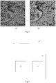
- Figure 4 illustrates an improvement in resolution of image data produced by embodiments of the present invention.
- Figure 4(a) is an image of a resolution test pattern, where the positions of the specimen are well characterised i.e. at a known position subject to low position error.
- Figure 4(b) is an image reconstructed from the same data, where random errors have been introduced into the measured specimen positions representing poor positioning accuracy. As can be observed, the resulting image is of lower quality than Figure 4(a).
- Figure 4(c) is an image after correcting for these position errors present in Figure 4(b) using an embodiment of the present invention.
- Figure 5(a) shows an image of a bee's hind leg obtained by a ptychographic experimental method. A translation stage of poor accuracy was used to carry out the experiment from which this image resulted, leading to the mottled noise pattern seen in the clear area to the right of the bee's leg, and poorly defined features, such as hairs, within the leg itself.
- Figure 5(b) is an image reconstructed from the same data using an embodiment of the invention. It can be observed that both the clear area and the structure of the bee's leg have been significantly improved in Figure 5(b) .
- Figure 6(a) illustrates an image produced using image data obtained with a subject (lily pollen) supported on an optical bench which suffers from backlash. The optical alignment for this experiment was imperfect.
- Figure 6(b) shows an image produced of the same subject after position correction according to an embodiment of the invention where it can be seen that the quality of the image has improved.
- an offset vector V is determined and the effect of the application of the offset vector to the wavefront based thereon is compared against the current best correction vector for that probe position (CBC j ).
- more than one offset vector is determined and a respective number of wavefronts are calculated based on each of the offset vectors.
- the method may determine an accurate current best correction vector more quickly.
- a set comprising a plurality of initial offset vectors are determined.
- Each of the set of vectors may be determined as previously explained with reference to Figure 2 .
- step 210 a plurality of estimates of exit waves are determined.
- An estimated exit wave is determined for each of the set of offset vectors.
- step 240 the modulus of each ⁇ j,m '( u ) is compared against I j , as in equation 7 previously described, to provide a set of errors E m each indicating a difference between the wavefront with the respective vector applied and the measured intensity at the measurement plane.
- the lowest error E m may then be compared against the current best error for that probe position CBE j as in step 241 to determine whether the current best correction vector CBC j and current best error CBE j should be updated as in steps 242, 243.
- At least a portion of the estimated wavefront at the plane of the detector having the lowest error is updated based on the measured diffraction pattern as in step 230 described above.
- Embodiments of the invention may also correct for global positioning errors.
- Global positioning errors may be caused, for example, by a relative rotation of the positioning stage and the detector, inaccurate measurement of the specimen-detector distance which causes a scaling error, or a linear drift during data acquisition.
- the term "global” is understood to be an error which is applied to all probe positions, although each probe position may also be subject to a "local" error specific to that probe position, as previously described
- the previously described offset vector V is referred to as V l,j wherein the subscript l indicates that the vector is for correction of a local error associated with the probe position j.
- correction scalars C r and C s are introduced, wherein C r is a rotation correction factor and C s is a scaling correction factor.
- C r is a rotation correction factor
- C s is a scaling correction factor.
- C r represents an angle to correct for a global rotation, which may be stored in radians
- C s represents a scaling factor
- V l,j a correction vector for each probe position.
- Embodiments of the invention may be envisaged where only a single group of correction vector V l,j and correction factors C r and C s are considered for each probe position during each iteration. However, for the purposes of explanation, an embodiment will be explained where a set of M groups of vectors V l,j and correction factors C r and C s are considered.
- a combined offset C j , m tot is determined by trial and error according to:
- C j , m tot CBC l , j + c l ⁇ l , m + R j cos C r + c r ⁇ r , m ⁇ 1 sin C r + c r ⁇ r , m ⁇ 1 + R j C s + c s ⁇ s , m
- the offset vector V c(randomx, randomy).
- c l is the previously described offset value c and ⁇ l ,m is a vector of two random numbers (random, randomy).
- c l ⁇ l,m may have a value in a predetermined range, such as the range ⁇ 1.
- the variables c l , c r and c s are scaling values which may be reduced as iterations of the method progress, either linearly or step-wise, as previously explained. The scaling values may decrease independently i.e. according to a different number of iterations and/or rate to a small or zero value.
- the vectors R j have mean x and y values equal to 0. If the position grid is centred around another value then the rotation and scaling may result in a large global translation which increases the size of the matrices representing the object and probe functions unnecessarily.
- the combined offset C j , m tot includes correction for local probe position error, global rotation and global scaling.
- the method proceeds as previously described to find a combined offset C j , m tot of the set of M offsets having a lowest error. If the error is lower than the current best correction vector CBC j for that probe position then CBC j and the global scalars C r and C s are updated in step 242 as: CBC l , j ⁇ CBC l , j + c ⁇ l , m C r ⁇ C r + c r ⁇ r , m C s ⁇ C s + c s ⁇ s , m
- Embodiments of the invention may be envisaged which determine correction factors for other global errors, such as global drift.
- further scalars such as C d are included in the calculation of the combined offset C j , m tot as, for example: j ⁇ J 2 C d + c d ⁇ d , m
- the factor J/2 in the above equation ensures that drift does not introduce a large global translation which increase the size of the matrices representing the object and probe functions unnecessarily.
- the J/2 term may be omitted or may be a different value.
- Figure 8 illustrates the correction of position errors by embodiments of the present invention.
- Figure 8(a) illustrates the performance of a prior art ePIE embodiment, shown in Figure 8(a) as diffraction pattern error, against an embodiment in which only a local position error is corrected, and an embodiment in which global rotation and scaling are also corrected.
- correction of only local position error improves upon the prior art ePIE method, whilst additional correction for rotation and scaling improves still further.
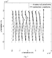
- Figure 8(b) illustrates a performance of a plurality of runs (operations) of an embodiment of the invention including both local and global position correction. For 10 runs each calculating 10 correction vectors for each of 100 positions, the plot compares these sets of 10 corrections to their means and shows that the same position is determined to within 60nm (0.04 pixels) for each of the 10 runs.
- Figure 8(c) shows a graph of the corrections made to probe positions showing how rotation, scaling and backlash errors are corrected.
- Backlash is a positioning error resulting from a change in direction of a translation stage, e.g. from left to right or from up to down.
- Figure 9 illustrates an apparatus 700 according to an embodiment of the invention.
- the apparatus 700 is arranged to determine image data for an object.
- the image data may, in some embodiments, be used to generate a visible image of the object.
- the visible image may, for example, be output to a display device.
- the apparatus 700 comprises a detector 710 for detecting an intensity of radiation falling thereon.
- the detector 710 corresponds to the detector 50 shown in Figure 1 arranged to record a diffraction pattern formed by radiation scattered by the target object.
- the detector may comprise a plurality of detecting elements each capable of outputting a signal indicative of the intensity of radiation falling thereon.
- the detector may be a CCD device, or similar.
- the detector 710 is communicably coupled to a processing unit 720 which is arranged to determine the image data based on the radiation intensity detected by the detector 710.
- the processing unit 720 comprises a memory 730 and a data processor 740, such as a CPU. Although Figure 7 shows the processing unit 720 comprising one memory, the processing unit 720 may comprise two or more memories.
- the processing unit 720 may comprise more than one data processor 740, and each data processor may comprise one or more processing cores.
- the memory 730 may be arranged to store measured radiation intensity data I s ( j ) ( u ) corresponding to a plurality of probe positions.
- the data processor 740 may implement a method according to an embodiment of the invention, such as that shown in Figure 2 and previously described.
- the data processor may store determined image data in the memory 730.
- embodiments of the present invention can be realised in the form of hardware, software or a combination of hardware and software. Any such software may be stored in the form of volatile or non-volatile storage such as, for example, a storage device like a ROM, whether erasable or rewritable or not, or in the form of memory such as, for example, RAM, memory chips, device or integrated circuits or on an optically or magnetically readable medium such as, for example, a CD, DVD, magnetic disk or magnetic tape. It will be appreciated that the storage devices and storage media are embodiments of machine-readable storage that are suitable for storing a program or programs that, when executed, implement embodiments of the present invention.
- embodiments provide a program comprising code for implementing a system or method as claimed in any preceding claim and a machine readable storage storing such a program. Still further, embodiments of the present invention may be conveyed electronically via any medium such as a communication signal carried over a wired or wireless connection and embodiments suitably encompass the same.
Landscapes
- Physics & Mathematics (AREA)
- General Physics & Mathematics (AREA)
- Engineering & Computer Science (AREA)
- Theoretical Computer Science (AREA)
- Health & Medical Sciences (AREA)
- Life Sciences & Earth Sciences (AREA)
- Chemical & Material Sciences (AREA)
- Analytical Chemistry (AREA)
- Biochemistry (AREA)
- General Health & Medical Sciences (AREA)
- Immunology (AREA)
- Pathology (AREA)
- Analysing Materials By The Use Of Radiation (AREA)
- Measurement Of Radiation (AREA)
- Apparatus For Radiation Diagnosis (AREA)
Applications Claiming Priority (2)
| Application Number | Priority Date | Filing Date | Title |
|---|---|---|---|
| GBGB1107053.9A GB201107053D0 (en) | 2011-04-27 | 2011-04-27 | Improvements in providing image data |
| PCT/GB2012/050929 WO2012146929A1 (en) | 2011-04-27 | 2012-04-27 | A method and apparatus for providing image data for constructing an image of a region of a target object |
Publications (2)
| Publication Number | Publication Date |
|---|---|
| EP2702556A1 EP2702556A1 (en) | 2014-03-05 |
| EP2702556B1 true EP2702556B1 (en) | 2017-10-18 |
Family
ID=44168625
Family Applications (1)
| Application Number | Title | Priority Date | Filing Date |
|---|---|---|---|
| EP12717463.9A Active EP2702556B1 (en) | 2011-04-27 | 2012-04-27 | A method and apparatus for providing image data for constructing an image of a region of a target object |
Country Status (9)
Families Citing this family (21)
| Publication number | Priority date | Publication date | Assignee | Title |
|---|---|---|---|---|
| GB201215558D0 (en) * | 2012-08-31 | 2012-10-17 | Phase Focus Ltd | Improvements in phase retrieval |
| US9864184B2 (en) | 2012-10-30 | 2018-01-09 | California Institute Of Technology | Embedded pupil function recovery for fourier ptychographic imaging devices |
| US9892812B2 (en) | 2012-10-30 | 2018-02-13 | California Institute Of Technology | Fourier ptychographic x-ray imaging systems, devices, and methods |
| US10652444B2 (en) | 2012-10-30 | 2020-05-12 | California Institute Of Technology | Multiplexed Fourier ptychography imaging systems and methods |
| WO2015017730A1 (en) | 2013-07-31 | 2015-02-05 | California Institute Of Technoloby | Aperture scanning fourier ptychographic imaging |
| CN110082900B (zh) | 2013-08-22 | 2022-05-13 | 加州理工学院 | 可变照明傅立叶重叠关联成像设备、系统以及方法 |
| US11468557B2 (en) | 2014-03-13 | 2022-10-11 | California Institute Of Technology | Free orientation fourier camera |
| US10162161B2 (en) * | 2014-05-13 | 2018-12-25 | California Institute Of Technology | Ptychography imaging systems and methods with convex relaxation |
| CN110873957A (zh) | 2014-12-22 | 2020-03-10 | 加州理工学院 | 用于厚样本的epi照明傅立叶重叠关联成像 |
| CN107209362B (zh) | 2015-01-21 | 2020-11-06 | 加州理工学院 | 傅立叶重叠关联断层摄影 |
| CA2970053A1 (en) | 2015-01-26 | 2016-08-04 | California Institute Of Technology | Multi-well fourier ptychographic and fluorescence imaging |
| US10684458B2 (en) | 2015-03-13 | 2020-06-16 | California Institute Of Technology | Correcting for aberrations in incoherent imaging systems using fourier ptychographic techniques |
| US9993149B2 (en) | 2015-03-25 | 2018-06-12 | California Institute Of Technology | Fourier ptychographic retinal imaging methods and systems |
| US10228550B2 (en) | 2015-05-21 | 2019-03-12 | California Institute Of Technology | Laser-based Fourier ptychographic imaging systems and methods |
| EP3106862B1 (en) * | 2015-06-18 | 2019-01-16 | FEI Company | Method of ptychographic imaging |
| US10568507B2 (en) | 2016-06-10 | 2020-02-25 | California Institute Of Technology | Pupil ptychography methods and systems |
| US11092795B2 (en) | 2016-06-10 | 2021-08-17 | California Institute Of Technology | Systems and methods for coded-aperture-based correction of aberration obtained from Fourier ptychography |
| WO2019090149A1 (en) | 2017-11-03 | 2019-05-09 | California Institute Of Technology | Parallel digital imaging acquisition and restoration methods and systems |
| WO2022183078A1 (en) | 2021-02-25 | 2022-09-01 | California Institute Of Technology | Computational refocusing-assisted deep learning |
| US12367563B2 (en) * | 2021-03-25 | 2025-07-22 | Government Of The United States Of America, As Represented By The Secretary Of Commerce | Tomographic reconstruction apparatus and removing diffraction effects in a tomographic image |
| KR102789554B1 (ko) * | 2023-05-03 | 2025-04-04 | 고려대학교 산학협력단 | 반사 행렬 데이터에 기반한 켤레 적응광학 알고리즘을 이용하여 타겟 이미지를 보정 및 복원하는 이미징 장치 및 방법 |
Family Cites Families (38)
| Publication number | Priority date | Publication date | Assignee | Title |
|---|---|---|---|---|
| US5570180A (en) | 1993-08-27 | 1996-10-29 | Minolta Co., Ltd. | Spectrometer provided with an optical shutter |
| US5717733A (en) | 1995-05-31 | 1998-02-10 | Quanta Vision, Inc. | X-ray and neutron diffractometric imaging of the internal structure of objects |
| US6809829B1 (en) | 1999-05-19 | 2004-10-26 | Matsushita Electric Industrial Co., Ltd. | Method and apparatus for evaluating aberrations of optical element and method and apparatus for adjusting optical unit and lens |
| US6304330B1 (en) | 1999-10-06 | 2001-10-16 | Metrolaser, Inc. | Methods and apparatus for splitting, imaging, and measuring wavefronts in interferometry |
| US6545790B2 (en) | 1999-11-08 | 2003-04-08 | Ralph W. Gerchberg | System and method for recovering phase information of a wave front |
| US6809845B1 (en) | 2002-09-25 | 2004-10-26 | University Of South Florida | Phase imaging using multi-wavelength digital holography |
| US7057735B2 (en) | 2002-11-14 | 2006-06-06 | Fitel U.S.A. Corp. | Method for measuring the optical and physical thickness of optically transparent objects |
| GB0314444D0 (en) | 2003-06-20 | 2003-07-23 | Univ Heriot Watt | Novel wavefront sensor |
| GB2403616A (en) | 2003-06-30 | 2005-01-05 | Univ Sheffield Hallam | Diffraction pattern imaging using moving aperture. |
| US7630528B2 (en) | 2004-03-02 | 2009-12-08 | Koninklijke Philips Electronics N.V. | Motion compensation |
| GB0409572D0 (en) | 2004-04-29 | 2004-06-02 | Univ Sheffield | High resolution imaging |
| US20050280813A1 (en) | 2004-06-16 | 2005-12-22 | Jones Howland D T | Infrared spectroscopy as an assist for cytological investigation |
| ES2279665B2 (es) | 2004-12-23 | 2008-04-16 | Universidade De Santiago De Compostela | Interferometro de difraccion por orificio, ido, para inspeccion y medida de componentes opticos oftalmicos. |
| JP3762420B2 (ja) | 2004-12-28 | 2006-04-05 | 株式会社リコー | 屈折率分布の測定方法及び装置 |
| JP3932303B2 (ja) | 2005-05-13 | 2007-06-20 | 独立行政法人放射線医学総合研究所 | 臓器動態の定量化方法、装置、臓器位置の予測方法、装置、放射線照射方法、装置及び臓器異常検出装置 |
| US7626708B2 (en) | 2006-04-28 | 2009-12-01 | Chao-Wen Liang | Phase shifting grating-slit test for optical surface reconstruction |
| US20080048102A1 (en) | 2006-08-22 | 2008-02-28 | Eastman Kodak Company | Optically enhanced multi-spectral detector structure |
| US7734084B2 (en) | 2006-10-20 | 2010-06-08 | Hewlett-Packard Development Company, L.P. | Method and system for offset estimation and alignment |
| GB0709796D0 (en) | 2007-05-22 | 2007-06-27 | Phase Focus Ltd | Three dimensional imaging |
| US8233682B2 (en) | 2007-06-05 | 2012-07-31 | General Electric Company | Methods and systems for improving spatial and temporal resolution of computed images of moving objects |
| JP5689681B2 (ja) | 2007-08-17 | 2015-03-25 | レニショウ パブリック リミテッド カンパニーRenishaw Public Limited Company | 非接触プローブ |
| EP2063260A1 (en) | 2007-11-19 | 2009-05-27 | Lambda-X | Fourier transform deflectometry system and method |
| GB0817650D0 (en) | 2008-09-26 | 2008-11-05 | Phase Focus Ltd | Improvements in the field of imaging |
| GB0822149D0 (en) | 2008-12-04 | 2009-01-14 | Univ Sheffield | Provision of image data |
| JP5008650B2 (ja) | 2008-12-25 | 2012-08-22 | キヤノン株式会社 | 屈折率分布計測方法及び屈折率分布計測装置 |
| JP2010204755A (ja) | 2009-02-27 | 2010-09-16 | Tohoku Univ | 画像処理装置、画像再構成システム、画像処理方法およびプログラム |
| JP5328437B2 (ja) | 2009-03-25 | 2013-10-30 | キヤノン株式会社 | 透過波面測定方法、屈折率分布測定方法、光学素子の製造方法、及び透過波面測定装置 |
| GB0906449D0 (en) | 2009-04-15 | 2009-05-20 | Phase Focus Ltd | Improvements in imaging |
| US20120179425A1 (en) | 2009-09-15 | 2012-07-12 | University Of Sheffield | Method and apparatus for retrieving a phase of a wavefield |
| WO2011044218A1 (en) | 2009-10-08 | 2011-04-14 | Massachusetts Institute Of Technology | Phase from defocused color images |
| JP4968965B2 (ja) | 2009-11-18 | 2012-07-04 | キヤノン株式会社 | 屈折率分布の計測方法および計測装置 |
| JP4968966B2 (ja) | 2009-12-07 | 2012-07-04 | キヤノン株式会社 | 屈折率分布の計測方法および計測装置 |
| GB201006593D0 (en) | 2010-04-20 | 2010-06-02 | Phase Focus Ltd | Characteristic determination |
| JP5021054B2 (ja) | 2010-05-25 | 2012-09-05 | キヤノン株式会社 | 屈折率分布計測方法および屈折率分布計測装置 |
| JP4895409B2 (ja) | 2010-05-25 | 2012-03-14 | キヤノン株式会社 | 屈折率分布計測方法および屈折率分布計測装置 |
| GB2481589B (en) | 2010-06-28 | 2014-06-11 | Phase Focus Ltd | Calibration of a probe in ptychography |
| GB201016088D0 (en) | 2010-09-24 | 2010-11-10 | Phase Focus Ltd | Improvements in imaging |
| US9182289B2 (en) | 2011-10-14 | 2015-11-10 | Canon Kabushiki Kaisha | Apparatus and method for estimating wavefront parameters |
-
2011
- 2011-04-27 GB GBGB1107053.9A patent/GB201107053D0/en not_active Ceased
-
2012
- 2012-04-27 JP JP2014506932A patent/JP6012710B2/ja active Active
- 2012-04-27 CN CN201280020664.3A patent/CN103503022B/zh active Active
- 2012-04-27 DK DK12717463.9T patent/DK2702556T3/da active
- 2012-04-27 EP EP12717463.9A patent/EP2702556B1/en active Active
- 2012-04-27 KR KR1020137031217A patent/KR101892321B1/ko not_active Expired - Fee Related
- 2012-04-27 WO PCT/GB2012/050929 patent/WO2012146929A1/en active Application Filing
- 2012-04-27 US US14/114,086 patent/US9448160B2/en active Active
-
2013
- 2013-10-15 IL IL228898A patent/IL228898A/en active IP Right Grant
Non-Patent Citations (1)
| Title |
|---|
| None * |
Also Published As
| Publication number | Publication date |
|---|---|
| CN103503022B (zh) | 2017-06-30 |
| JP6012710B2 (ja) | 2016-10-25 |
| JP2014517268A (ja) | 2014-07-17 |
| WO2012146929A1 (en) | 2012-11-01 |
| KR20140053006A (ko) | 2014-05-07 |
| KR101892321B1 (ko) | 2018-09-28 |
| IL228898A0 (en) | 2013-12-31 |
| GB201107053D0 (en) | 2011-06-08 |
| DK2702556T3 (da) | 2017-11-13 |
| CN103503022A (zh) | 2014-01-08 |
| US9448160B2 (en) | 2016-09-20 |
| US20140043616A1 (en) | 2014-02-13 |
| EP2702556A1 (en) | 2014-03-05 |
| IL228898A (en) | 2017-09-28 |
Similar Documents
| Publication | Publication Date | Title |
|---|---|---|
| EP2702556B1 (en) | A method and apparatus for providing image data for constructing an image of a region of a target object | |
| EP2356487B1 (en) | Provision of image data | |
| US9322791B2 (en) | Phase retrieval from ptychography | |
| US7792246B2 (en) | High resolution imaging | |
| KR101810637B1 (ko) | 티코그래피에서 프로브의 보정 | |
| EP2646852B1 (en) | Improvements in providing image data | |
| EP2419777B1 (en) | Improvements in imaging | |
| EP2227705B1 (en) | Method and apparatus for providing image data | |
| EP2732274B1 (en) | Method and apparatus for position determination | |
| CN110411983A (zh) | 一种高分辨率衍射成像方法及装置 | |
| WO2017085519A1 (en) | Improved method ptychographic detector mapping |
Legal Events
| Date | Code | Title | Description |
|---|---|---|---|
| PUAI | Public reference made under article 153(3) epc to a published international application that has entered the european phase |
Free format text: ORIGINAL CODE: 0009012 |
|
| 17P | Request for examination filed |
Effective date: 20131024 |
|
| AK | Designated contracting states |
Kind code of ref document: A1 Designated state(s): AL AT BE BG CH CY CZ DE DK EE ES FI FR GB GR HR HU IE IS IT LI LT LU LV MC MK MT NL NO PL PT RO RS SE SI SK SM TR |
|
| DAX | Request for extension of the european patent (deleted) | ||
| 17Q | First examination report despatched |
Effective date: 20141204 |
|
| GRAP | Despatch of communication of intention to grant a patent |
Free format text: ORIGINAL CODE: EPIDOSNIGR1 |
|
| INTG | Intention to grant announced |
Effective date: 20170511 |
|
| GRAS | Grant fee paid |
Free format text: ORIGINAL CODE: EPIDOSNIGR3 |
|
| GRAA | (expected) grant |
Free format text: ORIGINAL CODE: 0009210 |
|
| AK | Designated contracting states |
Kind code of ref document: B1 Designated state(s): AL AT BE BG CH CY CZ DE DK EE ES FI FR GB GR HR HU IE IS IT LI LT LU LV MC MK MT NL NO PL PT RO RS SE SI SK SM TR |
|
| REG | Reference to a national code |
Ref country code: GB Ref legal event code: FG4D |
|
| REG | Reference to a national code |
Ref country code: CH Ref legal event code: EP Ref country code: CH Ref legal event code: NV Representative=s name: MICHELI AND CIE SA, CH |
|
| REG | Reference to a national code |
Ref country code: DK Ref legal event code: T3 Effective date: 20171108 |
|
| REG | Reference to a national code |
Ref country code: AT Ref legal event code: REF Ref document number: 938546 Country of ref document: AT Kind code of ref document: T Effective date: 20171115 Ref country code: IE Ref legal event code: FG4D |
|
| REG | Reference to a national code |
Ref country code: NL Ref legal event code: FP |
|
| REG | Reference to a national code |
Ref country code: SE Ref legal event code: TRGR |
|
| REG | Reference to a national code |
Ref country code: DE Ref legal event code: R096 Ref document number: 602012038637 Country of ref document: DE |
|
| REG | Reference to a national code |
Ref country code: LT Ref legal event code: MG4D |
|
| REG | Reference to a national code |
Ref country code: AT Ref legal event code: MK05 Ref document number: 938546 Country of ref document: AT Kind code of ref document: T Effective date: 20171018 |
|
| PG25 | Lapsed in a contracting state [announced via postgrant information from national office to epo] |
Ref country code: LT Free format text: LAPSE BECAUSE OF FAILURE TO SUBMIT A TRANSLATION OF THE DESCRIPTION OR TO PAY THE FEE WITHIN THE PRESCRIBED TIME-LIMIT Effective date: 20171018 Ref country code: FI Free format text: LAPSE BECAUSE OF FAILURE TO SUBMIT A TRANSLATION OF THE DESCRIPTION OR TO PAY THE FEE WITHIN THE PRESCRIBED TIME-LIMIT Effective date: 20171018 Ref country code: ES Free format text: LAPSE BECAUSE OF FAILURE TO SUBMIT A TRANSLATION OF THE DESCRIPTION OR TO PAY THE FEE WITHIN THE PRESCRIBED TIME-LIMIT Effective date: 20171018 Ref country code: NO Free format text: LAPSE BECAUSE OF FAILURE TO SUBMIT A TRANSLATION OF THE DESCRIPTION OR TO PAY THE FEE WITHIN THE PRESCRIBED TIME-LIMIT Effective date: 20180118 |
|
| PG25 | Lapsed in a contracting state [announced via postgrant information from national office to epo] |
Ref country code: HR Free format text: LAPSE BECAUSE OF FAILURE TO SUBMIT A TRANSLATION OF THE DESCRIPTION OR TO PAY THE FEE WITHIN THE PRESCRIBED TIME-LIMIT Effective date: 20171018 Ref country code: GR Free format text: LAPSE BECAUSE OF FAILURE TO SUBMIT A TRANSLATION OF THE DESCRIPTION OR TO PAY THE FEE WITHIN THE PRESCRIBED TIME-LIMIT Effective date: 20180119 Ref country code: LV Free format text: LAPSE BECAUSE OF FAILURE TO SUBMIT A TRANSLATION OF THE DESCRIPTION OR TO PAY THE FEE WITHIN THE PRESCRIBED TIME-LIMIT Effective date: 20171018 Ref country code: IS Free format text: LAPSE BECAUSE OF FAILURE TO SUBMIT A TRANSLATION OF THE DESCRIPTION OR TO PAY THE FEE WITHIN THE PRESCRIBED TIME-LIMIT Effective date: 20180218 Ref country code: RS Free format text: LAPSE BECAUSE OF FAILURE TO SUBMIT A TRANSLATION OF THE DESCRIPTION OR TO PAY THE FEE WITHIN THE PRESCRIBED TIME-LIMIT Effective date: 20171018 Ref country code: BG Free format text: LAPSE BECAUSE OF FAILURE TO SUBMIT A TRANSLATION OF THE DESCRIPTION OR TO PAY THE FEE WITHIN THE PRESCRIBED TIME-LIMIT Effective date: 20180118 Ref country code: AT Free format text: LAPSE BECAUSE OF FAILURE TO SUBMIT A TRANSLATION OF THE DESCRIPTION OR TO PAY THE FEE WITHIN THE PRESCRIBED TIME-LIMIT Effective date: 20171018 |
|
| REG | Reference to a national code |
Ref country code: DE Ref legal event code: R097 Ref document number: 602012038637 Country of ref document: DE |
|
| PG25 | Lapsed in a contracting state [announced via postgrant information from national office to epo] |
Ref country code: SK Free format text: LAPSE BECAUSE OF FAILURE TO SUBMIT A TRANSLATION OF THE DESCRIPTION OR TO PAY THE FEE WITHIN THE PRESCRIBED TIME-LIMIT Effective date: 20171018 Ref country code: EE Free format text: LAPSE BECAUSE OF FAILURE TO SUBMIT A TRANSLATION OF THE DESCRIPTION OR TO PAY THE FEE WITHIN THE PRESCRIBED TIME-LIMIT Effective date: 20171018 |
|
| PLBE | No opposition filed within time limit |
Free format text: ORIGINAL CODE: 0009261 |
|
| STAA | Information on the status of an ep patent application or granted ep patent |
Free format text: STATUS: NO OPPOSITION FILED WITHIN TIME LIMIT |
|
| PG25 | Lapsed in a contracting state [announced via postgrant information from national office to epo] |
Ref country code: PL Free format text: LAPSE BECAUSE OF FAILURE TO SUBMIT A TRANSLATION OF THE DESCRIPTION OR TO PAY THE FEE WITHIN THE PRESCRIBED TIME-LIMIT Effective date: 20171018 Ref country code: RO Free format text: LAPSE BECAUSE OF FAILURE TO SUBMIT A TRANSLATION OF THE DESCRIPTION OR TO PAY THE FEE WITHIN THE PRESCRIBED TIME-LIMIT Effective date: 20171018 Ref country code: SM Free format text: LAPSE BECAUSE OF FAILURE TO SUBMIT A TRANSLATION OF THE DESCRIPTION OR TO PAY THE FEE WITHIN THE PRESCRIBED TIME-LIMIT Effective date: 20171018 |
|
| 26N | No opposition filed |
Effective date: 20180719 |
|
| REG | Reference to a national code |
Ref country code: DK Ref legal event code: EBP Effective date: 20180430 |
|
| PG25 | Lapsed in a contracting state [announced via postgrant information from national office to epo] |
Ref country code: SI Free format text: LAPSE BECAUSE OF FAILURE TO SUBMIT A TRANSLATION OF THE DESCRIPTION OR TO PAY THE FEE WITHIN THE PRESCRIBED TIME-LIMIT Effective date: 20171018 Ref country code: MC Free format text: LAPSE BECAUSE OF FAILURE TO SUBMIT A TRANSLATION OF THE DESCRIPTION OR TO PAY THE FEE WITHIN THE PRESCRIBED TIME-LIMIT Effective date: 20171018 |
|
| REG | Reference to a national code |
Ref country code: SE Ref legal event code: EUG |
|
| REG | Reference to a national code |
Ref country code: BE Ref legal event code: MM Effective date: 20180430 |
|
| REG | Reference to a national code |
Ref country code: IE Ref legal event code: MM4A |
|
| PG25 | Lapsed in a contracting state [announced via postgrant information from national office to epo] |
Ref country code: LU Free format text: LAPSE BECAUSE OF NON-PAYMENT OF DUE FEES Effective date: 20180427 Ref country code: SE Free format text: LAPSE BECAUSE OF NON-PAYMENT OF DUE FEES Effective date: 20180428 |
|
| PG25 | Lapsed in a contracting state [announced via postgrant information from national office to epo] |
Ref country code: BE Free format text: LAPSE BECAUSE OF NON-PAYMENT OF DUE FEES Effective date: 20180430 |
|
| PG25 | Lapsed in a contracting state [announced via postgrant information from national office to epo] |
Ref country code: FR Free format text: LAPSE BECAUSE OF NON-PAYMENT OF DUE FEES Effective date: 20180430 Ref country code: IT Free format text: LAPSE BECAUSE OF NON-PAYMENT OF DUE FEES Effective date: 20180427 Ref country code: IE Free format text: LAPSE BECAUSE OF NON-PAYMENT OF DUE FEES Effective date: 20180427 |
|
| PG25 | Lapsed in a contracting state [announced via postgrant information from national office to epo] |
Ref country code: DK Free format text: LAPSE BECAUSE OF NON-PAYMENT OF DUE FEES Effective date: 20180430 |
|
| PG25 | Lapsed in a contracting state [announced via postgrant information from national office to epo] |
Ref country code: MT Free format text: LAPSE BECAUSE OF NON-PAYMENT OF DUE FEES Effective date: 20180427 |
|
| PG25 | Lapsed in a contracting state [announced via postgrant information from national office to epo] |
Ref country code: TR Free format text: LAPSE BECAUSE OF FAILURE TO SUBMIT A TRANSLATION OF THE DESCRIPTION OR TO PAY THE FEE WITHIN THE PRESCRIBED TIME-LIMIT Effective date: 20171018 |
|
| PG25 | Lapsed in a contracting state [announced via postgrant information from national office to epo] |
Ref country code: HU Free format text: LAPSE BECAUSE OF FAILURE TO SUBMIT A TRANSLATION OF THE DESCRIPTION OR TO PAY THE FEE WITHIN THE PRESCRIBED TIME-LIMIT; INVALID AB INITIO Effective date: 20120427 Ref country code: PT Free format text: LAPSE BECAUSE OF FAILURE TO SUBMIT A TRANSLATION OF THE DESCRIPTION OR TO PAY THE FEE WITHIN THE PRESCRIBED TIME-LIMIT Effective date: 20171018 |
|
| PG25 | Lapsed in a contracting state [announced via postgrant information from national office to epo] |
Ref country code: MK Free format text: LAPSE BECAUSE OF NON-PAYMENT OF DUE FEES Effective date: 20171018 Ref country code: CY Free format text: LAPSE BECAUSE OF FAILURE TO SUBMIT A TRANSLATION OF THE DESCRIPTION OR TO PAY THE FEE WITHIN THE PRESCRIBED TIME-LIMIT Effective date: 20171018 |
|
| PG25 | Lapsed in a contracting state [announced via postgrant information from national office to epo] |
Ref country code: AL Free format text: LAPSE BECAUSE OF FAILURE TO SUBMIT A TRANSLATION OF THE DESCRIPTION OR TO PAY THE FEE WITHIN THE PRESCRIBED TIME-LIMIT Effective date: 20171018 |
|
| PGFP | Annual fee paid to national office [announced via postgrant information from national office to epo] |
Ref country code: CH Payment date: 20200511 Year of fee payment: 9 |
|
| PG25 | Lapsed in a contracting state [announced via postgrant information from national office to epo] |
Ref country code: LI Free format text: LAPSE BECAUSE OF NON-PAYMENT OF DUE FEES Effective date: 20210430 Ref country code: CH Free format text: LAPSE BECAUSE OF NON-PAYMENT OF DUE FEES Effective date: 20210430 |
|
| REG | Reference to a national code |
Ref country code: DE Ref legal event code: R081 Ref document number: 602012038637 Country of ref document: DE Owner name: BRUKER AXS LLC, WILMINGTON, US Free format text: FORMER OWNER: PHASE FOCUS LIMITED, SHEFFIELD, SOUTH YORKSHIRE, GB |
|
| REG | Reference to a national code |
Ref country code: GB Ref legal event code: 732E Free format text: REGISTERED BETWEEN 20241205 AND 20241211 |
|
| PGFP | Annual fee paid to national office [announced via postgrant information from national office to epo] |
Ref country code: NL Payment date: 20250414 Year of fee payment: 14 |
|
| REG | Reference to a national code |
Ref country code: NL Ref legal event code: PD Owner name: BRUKER AXS LLC; US Free format text: DETAILS ASSIGNMENT: CHANGE OF OWNER(S), ASSIGNMENT; FORMER OWNER NAME: PHASE FOCUS LIMITED Effective date: 20250623 |
|
| PGFP | Annual fee paid to national office [announced via postgrant information from national office to epo] |
Ref country code: DE Payment date: 20250417 Year of fee payment: 14 |
|
| PGFP | Annual fee paid to national office [announced via postgrant information from national office to epo] |
Ref country code: GB Payment date: 20250423 Year of fee payment: 14 |
|
| PGFP | Annual fee paid to national office [announced via postgrant information from national office to epo] |
Ref country code: CZ Payment date: 20250415 Year of fee payment: 14 |