EP2701862B1 - Method and device for producing flanged drawn parts with simultaneous trimming - Google Patents
Method and device for producing flanged drawn parts with simultaneous trimming Download PDFInfo
- Publication number
- EP2701862B1 EP2701862B1 EP12717670.9A EP12717670A EP2701862B1 EP 2701862 B1 EP2701862 B1 EP 2701862B1 EP 12717670 A EP12717670 A EP 12717670A EP 2701862 B1 EP2701862 B1 EP 2701862B1
- Authority
- EP
- European Patent Office
- Prior art keywords
- region
- blank
- cutting edge
- drawing die
- flange
- Prior art date
- Legal status (The legal status is an assumption and is not a legal conclusion. Google has not performed a legal analysis and makes no representation as to the accuracy of the status listed.)
- Active
Links
- 238000000034 method Methods 0.000 title claims description 50
- 238000009966 trimming Methods 0.000 title description 20
- 238000005520 cutting process Methods 0.000 claims description 84
- 239000000463 material Substances 0.000 claims description 12
- 238000004519 manufacturing process Methods 0.000 claims description 6
- 239000002184 metal Substances 0.000 claims description 2
- 230000007704 transition Effects 0.000 claims description 2
- 239000011265 semifinished product Substances 0.000 description 4
- 238000013461 design Methods 0.000 description 3
- 238000010276 construction Methods 0.000 description 2
- 238000007373 indentation Methods 0.000 description 2
- 230000003993 interaction Effects 0.000 description 2
- 238000007790 scraping Methods 0.000 description 2
- 229910000831 Steel Inorganic materials 0.000 description 1
- 238000007796 conventional method Methods 0.000 description 1
- 238000003780 insertion Methods 0.000 description 1
- 230000037431 insertion Effects 0.000 description 1
- 238000012423 maintenance Methods 0.000 description 1
- BASFCYQUMIYNBI-UHFFFAOYSA-N platinum Chemical compound [Pt] BASFCYQUMIYNBI-UHFFFAOYSA-N 0.000 description 1
- 238000004080 punching Methods 0.000 description 1
- 238000000926 separation method Methods 0.000 description 1
- 239000010959 steel Substances 0.000 description 1
Images
Classifications
-
- B—PERFORMING OPERATIONS; TRANSPORTING
- B21—MECHANICAL METAL-WORKING WITHOUT ESSENTIALLY REMOVING MATERIAL; PUNCHING METAL
- B21D—WORKING OR PROCESSING OF SHEET METAL OR METAL TUBES, RODS OR PROFILES WITHOUT ESSENTIALLY REMOVING MATERIAL; PUNCHING METAL
- B21D22/00—Shaping without cutting, by stamping, spinning, or deep-drawing
- B21D22/02—Stamping using rigid devices or tools
-
- B—PERFORMING OPERATIONS; TRANSPORTING
- B21—MECHANICAL METAL-WORKING WITHOUT ESSENTIALLY REMOVING MATERIAL; PUNCHING METAL
- B21D—WORKING OR PROCESSING OF SHEET METAL OR METAL TUBES, RODS OR PROFILES WITHOUT ESSENTIALLY REMOVING MATERIAL; PUNCHING METAL
- B21D22/00—Shaping without cutting, by stamping, spinning, or deep-drawing
- B21D22/20—Deep-drawing
- B21D22/22—Deep-drawing with devices for holding the edge of the blanks
-
- B—PERFORMING OPERATIONS; TRANSPORTING
- B21—MECHANICAL METAL-WORKING WITHOUT ESSENTIALLY REMOVING MATERIAL; PUNCHING METAL
- B21D—WORKING OR PROCESSING OF SHEET METAL OR METAL TUBES, RODS OR PROFILES WITHOUT ESSENTIALLY REMOVING MATERIAL; PUNCHING METAL
- B21D22/00—Shaping without cutting, by stamping, spinning, or deep-drawing
- B21D22/20—Deep-drawing
- B21D22/30—Deep-drawing to finish articles formed by deep-drawing
-
- B—PERFORMING OPERATIONS; TRANSPORTING
- B21—MECHANICAL METAL-WORKING WITHOUT ESSENTIALLY REMOVING MATERIAL; PUNCHING METAL
- B21D—WORKING OR PROCESSING OF SHEET METAL OR METAL TUBES, RODS OR PROFILES WITHOUT ESSENTIALLY REMOVING MATERIAL; PUNCHING METAL
- B21D24/00—Special deep-drawing arrangements in, or in connection with, presses
- B21D24/16—Additional equipment in association with the tools, e.g. for shearing, for trimming
Definitions
- the invention relates to a method and an apparatus for producing flanged drawn parts from a flat and / or preformed metal board using a drawing die with at least one cutting edge, a blank holder and a drawing die, wherein the drawing die a frame portion, a flange portion and a support area for has the board, the board placed on the support area of the drawing die and formed by retracting the draw punch in the drawing die in the drawn part and simultaneously cut at the flange.
- the invention relates to a device for producing flanged drawn parts with a drawing punch, which has at least one cutting edge, at least one hold-down and a drawing die with a flange portion in which the flange is formed, a frame portion and bottom portion, in which Zargen- and bottom portion formed and a support area for the board before the drawing process.
- Deep-drawing presses do not have a high-precision tool guide, so that trimming operations in such presses are not possible or can only be carried out very difficult and expensive.
- WO 2008/025387 A1 discloses a method and a tool for hot working a circuit board, wherein cutting elements are provided in the dies of the tool. With the cutting elements, a trimming of the workpiece can be carried out simultaneously with the drawing process.
- the DE 10 2006 026 805 A1 discloses an apparatus and method for hot working a semi-finished product having a die, a punch and a blank holder.
- a cutting device is provided on the punch and die, which cuts the semi-finished during forming.
- the present invention has therefore set itself the task of providing a method and an apparatus for producing flanged drawn parts with process-integrated trimming, which or a simpler construction of the tool, a self-centering system and at the same time a process-reliable, dimensionally accurate production of allows flange-drawn parts.
- the object of a method is achieved in that the Bearing area increased relative to the flange and fixed, wherein the height difference corresponds to at least the wall thickness of the formed sheet, during the retraction of the drawing die in the drawing die the cutting punch provided on the cutting edge with a provided at the transition between support area and flange area rounding, so that over the flange area projecting areas of the board are separated during the further drawing process.
- the support area is raised in relation to the flange area and formed in a fixed manner, so that the tool as a whole can be of considerably simplified construction. Because the height difference between the support area and the flange area of the die corresponds at least to the thickness of the board, a perfect cutting process with the cutting edge of the drawing punch or the drawing die can be ensured. In addition, the fact that the at least one provided on the drawing punch Cutting edge engages with the provided between the support portion and flange portion rounding before completion of the drawing process, allows, in contrast to the conventional method, the flange portion is cut before the completion of the drawing operation.
- the method thus allows a particularly simple design of the tool, which manages without height-shifting areas and offers high flexibility of the arrangement of the flange.
- the infeed of the board during the drawing process can be controlled or adjusted via the height difference between the support area and the flange area as well as over the flange area width.
- the material flow during the drawing process and trimming is easily controllable in that the hold-down presses the region of the board to be severed during the drawing process and trimming the region of the board to be cut off onto the support region of the drawing die.
- the tensile load of the board during trimming thereby adjusted and thus influence the Cutting quality are taken.
- the semifinished product can in particular be clamped and stretched wrinkle-free.
- the rounding along the cutting line has a varying engagement height with the cutting edge of the drawing punch, wherein the board is continuously cut during the retraction of the draw punch into the drawing die, starting from the areas of the curves which are first engaged with the cutting edge of the drawing punch becomes.
- the cutting forces and the cutting stroke can be reduced significantly.
- the engagement height varying along the cutting line with the cutting edge of the drawing punch of the rounding ensures that the cutting edge of the drawing punch comes into engagement with the round at different timings of the drawing punch, so that the trimming of the board respectively first into the first engaged Begins areas of rounding and then propagates continuously towards the other areas.
- the cutting line formed by the rounding with the cutting edge can then have, for example, a wavy course or an inclined course.
- the rounding has a radius of at least 0.5 mm.
- a cutting edge with a maximum radius of 0.5 mm.
- the tool Due to the interaction of the cutting edge (sharp edge) with the rounding, the tool is self-centering and thus positively influences the cutting quality.
- the dimensional accuracy of the manufactured, flanged drawn parts can be further improved in a further embodiment of the method according to the invention that the board is pulled into a preform before pulling in the drawing die in a Vorziehgesenk and the preformed board provides a surplus of material, so that upon reaching the end position of the Drawing die the finished shaped and trimmed board is calibrated.
- the excess material can preferably be provided in the bottom region and / or in the drawing radius.
- the process can be further improved by hot-working the board in the drawing die.
- this is also optional for the preforming process.
- the blanks are heated to austenitizing temperature, thermoformed and rapidly cooled so that the drawn part is press hardened.
- lower forming forces result, on the other hand, a structure which is advantageous for the forming and which permits large degrees of deformation.
- the hot forming is used in blanks made of higher-strength or ultrahigh-strength steels, for example of the 22MnB5 type.
- the method according to the invention it is also possible, according to a further embodiment of the method according to the invention, to leave material along the cutting line, preferably in the form of webs, in other words. to produce an interrupted cutting line, whereby the drawn part is at least partially still connected to the trim area and at the same time can be removed from the tool (scrap removal via webs). In a further separation process, the cut area can be separated from the good part.
- a slit semifinished product which has at least one slot, preferably at least two slits in the trimming area, which extends from an edge of the semi-finished product to the cutting line, whereby the trimming area is divided into several individual parts during the trimming (Scrap division) and thus the bad part can be removed more easily from the tool, for example by means of scrap chutes.
- the object is achieved by a device in that the support area is increased and fixed with respect to the flange area, wherein the height difference between the support area and the flange portion of the drawing die corresponds at least to the wall thickness of the board to be formed, between Supporting portion and the flange portion is provided a rounding, which is in engagement with a cutting punch provided on the cutting edge and allows trimming of the board during the drawing process.
- the device according to the invention does not require a height-adjustable drawing die, so that the costs for the production of the train can be significantly reduced.
- the difference in height between the support area of the board and the flange area allows the flange of the drawn part to be formed very precisely into the flange area after it has been trimmed.
- the device allows a greater flexibility with respect to the orientation of the flange portion relative to the frame portion is achieved. The cost-effective tool with its simple design reduces wear and thus the cost of producing precise, flanged drawing parts.
- the indentation of the flange area of the drawn part can be controlled or adjusted via the height difference or over the flange width.
- a larger height difference between support area and flange area allows more material to be provided here and the flange area to have less feed.
- a minimum indentation must be ensured so that the drawn drawn part can still be removed from the tool.
- the rounding has an inlet radius of at least 0.5 mm.
- the precision of trimming the flange of the drawn part is improved in that the cutting edge of the drawing punch has a maximum radius of 0.5 mm.
- the rounding along the cutting line on a varying engagement height with the cutting edge so that the cutting edge at the beginning of the cutting process only point or area with the rounding engaged.
- the rounding which varies in its engagement height with the cutting edge, permits a continuous trimming along the cutting line by retracting the drawing punch into the drawing die.
- the cutting forces and the cutting impact during the drawing process are significantly reduced.
- the device according to the invention can be further improved in that the support area is connected to the drawing die in a highly precise manner, for example via a pinning, or is formed integrally with the drawing die. If the support area is formed integrally with the drawing die, the drawing die can be produced particularly inexpensively. On the other hand, there are significant advantages in the pinning of the support area with the drawing die in terms of maintenance. In this case, it is possible to replace the support area and possibly rework the rounding or cutting edge of the drawing die in a simple manner.
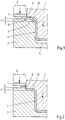
- FIG. 1 a first embodiment of a device according to the invention for the production of flanged drawing parts with a drawing punch 1, a drawing die 2 with a flange 3, in which the flange is formed, a frame portion 4 and a bottom portion 5, in which the Zargen- or bottom portions of the drawn part formed be and a support area 6 for supporting the board before the drawing process.
- the Device on a hold-7 and a rounding 8 between support area 6 and the flange portion 3.
- the rounding has an inlet radius of at least 0.5 mm, so that the material from the support area 6 can flow unhindered into the flange area.
- the support area 6 is raised relative to the flange area 3 and formed fixed.
- h indicates the height difference between the supporting area for the drawing board of the drawing die 6 and the flange area 3 of the drawing die. In the embodiment shown, h is slightly larger than the board thickness.
- the directional arrows each indicate the direction of movement of the blank holder 7 and the drawing punch 1.
- the drawing punch 1 also has a cutting edge 9, which preferably has a radius of 0.05 mm. As in Fig. 1 As shown, in the drawing process, the blank 10 is pulled into the drawing die until the cutting edge 9 engages the rounding 8. Preferably, the hold-down is shut down at the beginning of the drawing process, so that it presses the board 10 against the support area 6 of the board. By this measure, the flow of material can be additionally controlled during the drawing process.
- the drawing punch 1 moves the drawing punch 1, as in Fig. 2 shown, in the end position, the circuit board is cut due to the engagement of the cutting edge 9 of the drawing punch 1 with the rounding 8 of the support portion 6, so that over the flange portion 3 protruding parts of the board 10 are separated from this.
- the drawing die 2 is particularly simple design and still allows deep drawing with simultaneous trimming of the board.
- the support area 6 is in the present embodiment formed integrally with the drawing die, which corresponds to a particularly simple embodiment.
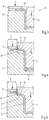
- Fig. 3 now shows in a schematic sectional view of a half of a device 11 for producing a preformed circuit board 12, which provides, for example in the bottom area a surplus of material.
- the device 11 for producing a preformed circuit board also consists of a die 13 and a drawing punch 14 and a hold-down 15.
- the preformed board 12 inserted in a device can not only be drawn to the final shape, but also circumcised and calibrated simultaneously.
- the preformed board 12 can not only be drawn to the final shape, but also circumcised and calibrated simultaneously.
- the drawing die 2 provided in the bottom region 5 of the drawing die excess material of the preformed board.
- a cutting edge 8 'and the drawing punch 1 a rounding 9' are provided.
- Fig. 5 shows schematically a device in the final position of the drawing die with calibrated, preformed board 12. The insertion of the board in the flange area is minimal and thus the drawn part so very accurate.
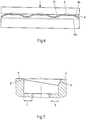
- Fig. 6 the rounding 8 between support area 6 and flange area 3 is shown schematically along its section line 8b.
- the section line 8b of the rounding 8 has a wave-shaped course, so that the cutting edge 9 of the drawing punch at the beginning of the cutting process only point or partially with the rounding 8 engages and the board can be continuously cut by retracting the drawing punch in the drawing die.
- 8a the target section contour of the rounding 8 is designated, which corresponds to the desired dimension of the board.
- the representation in Fig. 6 is not to scale. About a calibration, such as in 4 and 5 shown, the rounding can be easily corrected in one step.
- a sawtooth or a linear profile of the engagement height of the rounding can be used.
- Fig. 7 has on the left side of the rounding 8 a small inlet radius, for example, 1 mm.
- the inlet radius is significantly larger, for example, 5 mm. Accordingly, the cutting edge initially engages the left side first and continues its cut to the right side by retracting the draw punch into the die.
- the cutting gaps which are provided between the cutting edge 9, 8 'and rounding 8, 9', are preferably 0.05 mm to a maximum of 0.2 mm in order to ensure a particularly precise trimming of the board.
- the cutting edge of the drawing punch preferably has a maximum radius of 0.5 mm, in order to also ensure a particularly precise cutting process.
Description
Die Erfindung betrifft ein Verfahren und eine Vorrichtung zur Herstellung von flanschbehafteten Ziehteilen aus einer ebenen und/oder vorgeformten Platine aus Metall unter Verwendung eines Ziehstempels mit mindestens einer Schneidkante, eines Niederhalters und eines Ziehgesenks, wobei das Ziehgesenk einen Zargenbereich, einen Flanschbereich sowie einen Auflagebereich für die Platine aufweist, die Platine auf den Auflagebereich des Ziehgesenks aufgelegt und durch Einfahren des Ziehstempels in das Ziehgesenk in das Ziehteil umgeformt und gleichzeitig am Flanschbereich beschnitten wird. Daneben betrifft die Erfindung eine Vorrichtung zur Herstellung von flanschbehafteten Ziehteilen mit einem Ziehstempel, welcher mindestens eine Schneidkante aufweist, mindestens einem Niederhalter und einem Ziehgesenk mit einem Flanschbereich, in welchem der Flansch geformt wird, einem Zargenbereich und Bodenbereich, in welchem Zargen- und Bodenbereich geformt werden sowie einem Auflagebereich für die Platine vor dem Ziehvorgang.The invention relates to a method and an apparatus for producing flanged drawn parts from a flat and / or preformed metal board using a drawing die with at least one cutting edge, a blank holder and a drawing die, wherein the drawing die a frame portion, a flange portion and a support area for has the board, the board placed on the support area of the drawing die and formed by retracting the draw punch in the drawing die in the drawn part and simultaneously cut at the flange. In addition, the invention relates to a device for producing flanged drawn parts with a drawing punch, which has at least one cutting edge, at least one hold-down and a drawing die with a flange portion in which the flange is formed, a frame portion and bottom portion, in which Zargen- and bottom portion formed and a support area for the board before the drawing process.
Aus dem Stand der Technik sind Verfahren und Vorrichtungen zur Herstellung von flanschbehafteten Ziehteilen bekannt, mit welchen aus einer ebenen Platine Ziehteile durch Tiefziehen und Beschneiden in einem Arbeitshub hergestellt werden können. So ist aus dem
Tiefziehpressen haben keine hochgenaue Werkzeugführung, so dass Beschnittoperationen in solchen Pressen nicht möglich sind oder nur sehr schwierig und aufwendig durchgeführt werden können.Deep-drawing presses do not have a high-precision tool guide, so that trimming operations in such presses are not possible or can only be carried out very difficult and expensive.
Aus der
In der
Die
In der
Die vorliegende Erfindung hat sich daher zur Aufgabe gestellt, ein Verfahren und eine Vorrichtung zur Herstellung von flanschbehafteten Ziehteilen mit prozessintegriertem Beschneiden zur Verfügung zu stellen, welches bzw. welche einen einfacheren Aufbau des Werkzeugs, ein sich selbstzentrierendes System und gleichzeitig eine prozesssichere, maßgenaue Herstellung von flanschbehafteten Ziehteilen ermöglicht.The present invention has therefore set itself the task of providing a method and an apparatus for producing flanged drawn parts with process-integrated trimming, which or a simpler construction of the tool, a self-centering system and at the same time a process-reliable, dimensionally accurate production of allows flange-drawn parts.
Gemäß einer ersten Lehre der vorliegenden Erfindung wird die Aufgabe für ein Verfahren dadurch gelöst, dass der Auflagebereich gegenüber dem Flanschbereich erhöht und feststehend ausgebildet ist, wobei die Höhendifferenz mindestens der Wanddicke der umzuformenden Platine entspricht, während des Einfahrens des Ziehstempels in das Ziehgesenk die am Ziehstempel vorgesehene Schneidkante mit einer am Übergang zwischen Auflagebereich und Flanschbereich vorgesehenen Rundung in Eingriff kommt, so dass über den Flanschbereich überstehende Bereiche der Platine während des weiteren Ziehvorgangs abgetrennt werden.According to a first teaching of the present invention, the object of a method is achieved in that the Bearing area increased relative to the flange and fixed, wherein the height difference corresponds to at least the wall thickness of the formed sheet, during the retraction of the drawing die in the drawing die the cutting punch provided on the cutting edge with a provided at the transition between support area and flange area rounding, so that over the flange area projecting areas of the board are separated during the further drawing process.
Im Unterschied zu dem aus dem Stand der Technik bekannten Verfahren wird erfindungsgemäß der Auflagebereich gegenüber dem Flanschbereich erhöht und feststehend ausgebildet, so dass das Werkzeug insgesamt deutlich vereinfacht aufgebaut sein kann. Dadurch, dass die Höhendifferenz zwischen Auflagebereich und Flanschbereich des Gesenks mindestens der Dicke der Platine entspricht, kann ein einwandfreier Schneidprozess mit der Schneidkante des Ziehstempels oder des Ziehgesenks gewährleistet werden. Zusätzlich wird dadurch, dass die mindestens eine am Ziehstempel vorgesehene Schneidkante mit der zwischen dem Auflagebereich und Flanschbereich vorgesehenen Rundung vor Beendigung des Ziehvorgangs in Eingriff kommt, ermöglicht, dass im Gegensatz zu dem konventionellen Verfahren der Flanschbereich vor Beendigung des Ziehvorgangs beschnitten wird. Das Verfahren ermöglicht insofern einen besonders einfachen Aufbau des Werkzeugs, welches ohne höhenverschiebbare Bereiche auskommt und bietet hohe Flexibilität der Anordnung des Flansches. Über den Höhenunterschied zwischen Auflagebereich und Flanschbereich sowie über die Flanschbereichsbreite kann darüber hinaus der Einzug der Platine während des Ziehvorgangs gesteuert bzw. eingestellt werden.In contrast to the method known from the prior art, according to the invention, the support area is raised in relation to the flange area and formed in a fixed manner, so that the tool as a whole can be of considerably simplified construction. Because the height difference between the support area and the flange area of the die corresponds at least to the thickness of the board, a perfect cutting process with the cutting edge of the drawing punch or the drawing die can be ensured. In addition, the fact that the at least one provided on the drawing punch Cutting edge engages with the provided between the support portion and flange portion rounding before completion of the drawing process, allows, in contrast to the conventional method, the flange portion is cut before the completion of the drawing operation. The method thus allows a particularly simple design of the tool, which manages without height-shifting areas and offers high flexibility of the arrangement of the flange. In addition, the infeed of the board during the drawing process can be controlled or adjusted via the height difference between the support area and the flange area as well as over the flange area width.
Gleichzeitig wird durch das Zusammenwirken zwischen der Schneidkante am Ziehstempel und der gegenüberliegender Rundung am Ziehgesenk nicht nur positiv Einfluss auf das Schnittergebnis genommen, sondern aufgrund des Selbstzentrierungseffektes der Vorteil erreicht, dass das Werkzeug in konventionellem Tiefziehpressen eingesetzt werden kann, die üblicherweise keine exakte und genaue Stempelführung aufweisen und dadurch der Aufbau des Werkzeugs einfach gehalten werden kann.At the same time the interaction between the cutting edge on the punch and the opposite rounding on drawing die not only positively influence the cutting result, but due to the Selbstzentrierungseffektes achieved the advantage that the tool can be used in conventional deep-drawing presses, which usually no exact and accurate punch guide and thereby the structure of the tool can be kept simple.
Gemäß einer ersten Ausgestaltung des Verfahrens wird der Materialfluss während des Ziehvorgangs und des Beschneidens dadurch gut steuerbar, dass der Niederhalter den abzutrennenden Bereich der Platine während des Ziehvorgangs und des Beschneidens der abzutrennende Bereich der Platine auf den Auflagebereich des Ziehgesenks drückt. Insbesondere kann die Zugbelastung der Platine während des Beschneidens hierdurch eingestellt und damit Einfluss auf die Schneidqualität genommen werden. Bei Verwendung eines breiten Niederhalters sowie einer breiten Auflagefläche des Ziehgesenks kann das Halbzeug insbesondere faltenfrei geklemmt und abgestreckt werden.According to a first embodiment of the method, the material flow during the drawing process and trimming is easily controllable in that the hold-down presses the region of the board to be severed during the drawing process and trimming the region of the board to be cut off onto the support region of the drawing die. In particular, the tensile load of the board during trimming thereby adjusted and thus influence the Cutting quality are taken. When using a wide hold-down device and a wide support surface of the drawing die, the semifinished product can in particular be clamped and stretched wrinkle-free.
Gemäß einer nächsten Ausgestaltung des Verfahrens weist die Rundung entlang der Schnittlinie eine variierende Eingriffshöhe mit der Schneidkante des Ziehstempels auf, wobei die Platine ausgehend von den zuerst mit der Schneidkante des Ziehstempels in Eingriff stehenden Bereichen der Rundungen fortlaufend während des Einfahrens des Ziehstempels in das Ziehgesenk beschnitten wird. Im Unterschied zu dem aus dem Stand der Technik bekannten Verfahren, bei welchem das Beschneiden der Platine nach dem Ende des Ziehvorgangs auf der gesamte Länge der Schnittlinie gleichzeitig durchgeführt wird, können die Schnittkräfte und der Schnittschlag deutlich reduziert werden. Die entlang der Schnittlinie variierende Eingriffshöhe mit der Schneidkante des Ziehstempels der Rundung gewährleistet nämlich, dass die Schneidkante des Ziehstempels zu unterschiedlichen Zeitpunkten bzw. Positionen des Ziehstempels in Eingriff mit der Rundung kommt, so dass das Beschneiden der Platine jeweils zunächst in den zuerst in Eingriff stehenden Bereichen der Rundung beginnt und sich dann fortlaufend in Richtung der weiteren Bereiche fortpflanzt. Die durch die Rundung mit der Schneidkante gebildete Schnittlinie kann dann beispielsweise einen wellenförmigen Verlauf oder einen geneigten Verlauf aufweisen.According to a next embodiment of the method, the rounding along the cutting line has a varying engagement height with the cutting edge of the drawing punch, wherein the board is continuously cut during the retraction of the draw punch into the drawing die, starting from the areas of the curves which are first engaged with the cutting edge of the drawing punch becomes. In contrast to the method known from the prior art, in which the cutting of the blank after the end of the drawing operation is carried out simultaneously over the entire length of the cut line, the cutting forces and the cutting stroke can be reduced significantly. Namely, the engagement height varying along the cutting line with the cutting edge of the drawing punch of the rounding ensures that the cutting edge of the drawing punch comes into engagement with the round at different timings of the drawing punch, so that the trimming of the board respectively first into the first engaged Begins areas of rounding and then propagates continuously towards the other areas. The cutting line formed by the rounding with the cutting edge can then have, for example, a wavy course or an inclined course.
Bevorzugst weist die Rundung einen Radius von mindestens 0,5 mm auf. Um die Präzision des Beschneidens der Platine während des Ziehvorgangs zu erhöhen, ist es vorteilhaft, wenn eine Schneidkante mit einem Radius von maximal 0,5 mm verwendet wird.Preferably, the rounding has a radius of at least 0.5 mm. To the precision of trimming the board During the drawing process, it is advantageous to use a cutting edge with a maximum radius of 0.5 mm.
Gleiches gilt auch für eine nächste Ausführungsform des erfindungsgemäßen Verfahrens, bei welchem ein Schneidspalt von 0,05 mm bis maximal 0,2 mm zwischen Rundung und Schneidkante des Ziehstempels eingehalten wird.The same applies to a next embodiment of the method according to the invention, in which a cutting gap of 0.05 mm to a maximum of 0.2 mm between rounding and cutting edge of the drawing die is maintained.
Aufgrund der Zusammenwirkung der Schneidkante (scharfe Kante) mit der Rundung ist das Werkzeug selbstzentrierend aufgebaut und beeinflusst dadurch positiv die Schnittqualität.Due to the interaction of the cutting edge (sharp edge) with the rounding, the tool is self-centering and thus positively influences the cutting quality.
Die Maßhaltigkeit der hergestellten, flanschbehafteten Ziehteile kann gemäß einer weiteren Ausgestaltung des erfindungsgemäßen Verfahrens dadurch weiterverbessert werden, dass die Platine vor dem Ziehen im Ziehgesenk in einem Vorziehgesenk in eine Vorform gezogen wird und die vorgeformte Platine einen Materialüberschuss bereitstellt, so dass bei Erreichen der Endposition des Ziehstempels die fertig geformte und beschnittene Platine kalibriert wird. Der Materialüberschuss kann bevorzugt im Bodenbereich und/oder im Ziehradius zur Verfügung gestellt werden. Im Ergebnis kann durch diese zwei Arbeitsschritte, nämlich Vorformen und Endformen und Beschneiden ein hochmaßhaltiges, flanschbehaftetes Ziehteil mit einfachen Mitteln bereitgestellt werden.The dimensional accuracy of the manufactured, flanged drawn parts can be further improved in a further embodiment of the method according to the invention that the board is pulled into a preform before pulling in the drawing die in a Vorziehgesenk and the preformed board provides a surplus of material, so that upon reaching the end position of the Drawing die the finished shaped and trimmed board is calibrated. The excess material can preferably be provided in the bottom region and / or in the drawing radius. As a result, by these two operations, namely preforming and final forming and trimming, a high-gauge, flanged drawn part can be provided by simple means.
Schließlich kann das Verfahren weiter dadurch verbessert werden, dass die Platine im Ziehgesenk warmumgeformt wird. Dies gilt selbstverständlich auch optional für den Vorformprozess. Beim Warmumformen werden die Platinen auf Austenitisierungstemperatur erwärmt, warm umgeformt und dabei schnell abgekühlt so dass das Ziehteil pressgehärtet ist. Beim Warmumformen generell ergeben sich einerseits geringere Umformkräfte, andererseits ein für die Umformung vorteilhaftes Gefüge, welches große Umformgrade zulässt. Insbesondere wird die Warmumformung bei Platinen aus höher- bzw. höchstfesten Stählen, beispielsweise vom Typ 22MnB5, verwendet.Finally, the process can be further improved by hot-working the board in the drawing die. Of course, this is also optional for the preforming process. During hot forming, the blanks are heated to austenitizing temperature, thermoformed and rapidly cooled so that the drawn part is press hardened. In hot forming generally, on the one hand, lower forming forces result, on the other hand, a structure which is advantageous for the forming and which permits large degrees of deformation. In particular, the hot forming is used in blanks made of higher-strength or ultrahigh-strength steels, for example of the 22MnB5 type.
Alternativ ist es auch gemäß einer weitern Ausgestaltung des erfindungsgemäßen Verfahrens möglich, entlang der Schnittlinie bereichsweise Material, vorzugsweise in Form von Stegen, stehen zu lassen, d.h. eine unterbrochene Schnittlinie zu erzeugen, wodurch das Ziehteil zumindest teilweise noch mit dem Beschnittbereich verbunden ist und zugleich aus dem Werkzeug entnommen werden kann (Schrottabfuhr über Stegen). In einem weiteren Trennprozess kann der Beschnittbereich von dem Gut-Teil abgetrennt werden.Alternatively, it is also possible, according to a further embodiment of the method according to the invention, to leave material along the cutting line, preferably in the form of webs, in other words. to produce an interrupted cutting line, whereby the drawn part is at least partially still connected to the trim area and at the same time can be removed from the tool (scrap removal via webs). In a further separation process, the cut area can be separated from the good part.
Gemäß einer weiteren Ausgestaltung des erfindungsgemäßen Verfahrens kann ein "geschlitztes Halbzeug eingesetzt werden, das im Beschnittbereich mindestens einen Schlitz, vorzugsweise mindestens zwei Schlitze, aufweist, der von einer Kante des Halbzeugs bis zur Schnittlinie verläuft, wodurch während des Beschnitts der Beschnittbereich in mehrere Einzelteile zerfällt (Schrottzerteilung) und dadurch der Schlecht-Teil einfacher aus dem Werkzeug, beispielsweise über Schrottrutschen, entfernt werden kann.According to a further embodiment of the method according to the invention, a slit semifinished product can be used which has at least one slot, preferably at least two slits in the trimming area, which extends from an edge of the semi-finished product to the cutting line, whereby the trimming area is divided into several individual parts during the trimming (Scrap division) and thus the bad part can be removed more easily from the tool, for example by means of scrap chutes.
Gemäß einer zweiten Lehre der vorliegenden Erfindung wird die aufgezeigte Aufgabe durch eine Vorrichtung dadurch gelöst, dass der Auflagebereich gegenüber dem Flanschbereich erhöht und feststehend ausgebildet ist, wobei die Höhendifferenz zwischen dem Auflagebereich und dem Flanschbereich des Ziehgesenks mindestens der Wanddicke der umzuformenden Platine entspricht, zwischen dem Auflagebereich und dem Flanschbereich eine Rundung vorgesehen ist, welche mit einer am Ziehstempel vorgesehenen Schneidkante in Eingriff steht und ein Beschneiden der Platine während des Ziehvorgangs ermöglicht. Die erfindungsgemäße Vorrichtung kommt insofern ohne höhenverschiebbares Ziehgesenk aus, so dass die Kosten für die Erstellung des Werkzugs deutlich verringert werden können. Darüber hinaus erlaubt die Höhendifferenz zwischen dem Auflagebereich der Platine und dem Flanschbereich, dass der Flansch des Ziehteils sehr präzise in den Flanschbereich geformt werden kann, nachdem dieser beschnitten wurde. Zusätzlich ermöglicht die Vorrichtung, dass eine größere Flexibilität hinsichtlich der Ausrichtung des Flanschbereichs gegenüber dem Zargenbereich erzielt wird. Das kostengünstige Werkzeug mit seinem einfachen Aufbau verringert Verschleiß und damit auch die Kosten zur Herstellung von präzisen, flanschbehafteten Ziehteilen.According to a second teaching of the present invention, the object is achieved by a device in that the support area is increased and fixed with respect to the flange area, wherein the height difference between the support area and the flange portion of the drawing die corresponds at least to the wall thickness of the board to be formed, between Supporting portion and the flange portion is provided a rounding, which is in engagement with a cutting punch provided on the cutting edge and allows trimming of the board during the drawing process. The device according to the invention does not require a height-adjustable drawing die, so that the costs for the production of the train can be significantly reduced. Moreover, the difference in height between the support area of the board and the flange area allows the flange of the drawn part to be formed very precisely into the flange area after it has been trimmed. In addition, the device allows a greater flexibility with respect to the orientation of the flange portion relative to the frame portion is achieved. The cost-effective tool with its simple design reduces wear and thus the cost of producing precise, flanged drawing parts.
Entspricht die die Höhendifferenz zwischen dem Auflagebereich und dem Flanschbereich des Ziehgesenks mindestens der Wanddicke der umzuformenden Platine, kann der Einzug des Flanschbereichs des Ziehteils über die Höhendifferenz oder über die Flanschbereisbreite gesteuert bzw. eingestellt werden. Eine größere Höhendifferenz zwischen Auflagebereich und Flanschbereich ermöglicht, dass hier mehr Material bereitgestellt werden kann und der Flanschbereich einen geringeren Einzug aufweist. Selbstverständlich muss ein minimaler Einzug gewährleistet sein, so dass das gezogene Ziehteil noch aus dem Werkzeug entfernt werden kann.If the height difference between the support area and the flange area of the drawing die corresponds to at least the wall thickness of the board to be reshaped, the indentation of the flange area of the drawn part can be controlled or adjusted via the height difference or over the flange width. A larger height difference between support area and flange area allows more material to be provided here and the flange area to have less feed. Of course, a minimum indentation must be ensured so that the drawn drawn part can still be removed from the tool.
Um die Schnittqualität bei Eingriff der Rundung mit der Schneidkante zu verbessern und um eine verbesserte Selbstzentrierung des Systems am Ziehstempel/Ziehgesenk zu erreichen, ist es vorteilhaft, wenn die Rundung einen Einlaufradius von mindestens 0,5 mm aufweist.In order to improve the quality of cut when engaging the rounding with the cutting edge and to achieve an improved self-centering of the system on the drawing die / drawing die, it is advantageous if the rounding has an inlet radius of at least 0.5 mm.
Gemäß einer weiteren Ausgestaltung der erfindungsgemäßen Vorrichtung wird die Präzision des Beschneidens des Flansches des Ziehteils dadurch verbessert, dass die Schneidkante des Ziehstempels einen Radius von maximal 0,5 mm aufweist.According to a further embodiment of the device according to the invention, the precision of trimming the flange of the drawn part is improved in that the cutting edge of the drawing punch has a maximum radius of 0.5 mm.
Gleiches gilt auch für eine nächste Ausführungsform der erfindungsgemäßen Vorrichtung, gemäß welcher ein Schneidspalt zwischen der Schneidkante und der Rundung von 0,05 mm bis maximal 0,2 mm vorgesehen ist.The same applies to a next embodiment of the device according to the invention, according to which a cutting gap between the cutting edge and the rounding of 0.05 mm to a maximum of 0.2 mm is provided.
Um die Schneidkräfte aber auch den Schnittschlag während des Ziehvorgangs zu verringern, weist gemäß einer weiteren Ausführungsform der erfindungsgemäßen Vorrichtung die Rundung entlang der Schnittlinie eine variierende Eingriffshöhe mit der Schneidkante auf, so dass die Schneidkante zu Beginn des Schneidvorgangs nur punkt- oder bereichsweise mit der Rundung in Eingriff steht.In order to reduce the cutting forces but also the cutting impact during the drawing process, according to a further embodiment of the device according to the invention, the rounding along the cutting line on a varying engagement height with the cutting edge, so that the cutting edge at the beginning of the cutting process only point or area with the rounding engaged.
Wie bereits zum Verfahren ausgeführt, ermöglicht beispielsweise die in ihrer Eingriffshöhe mit der Schneidkante variierende Rundung einen fortlaufenden Beschnitt entlang der Schnittlinie durch Einfahren des Ziehstempels in das Ziehgesenk. Im Ergebnis werden die Schneidkräfte und der Schnittschlag während des Ziehvorgangs deutlich verringert.As already stated for the method, for example, the rounding, which varies in its engagement height with the cutting edge, permits a continuous trimming along the cutting line by retracting the drawing punch into the drawing die. As a result, the cutting forces and the cutting impact during the drawing process are significantly reduced.
Schließlich kann die erfindungsgemäße Vorrichtung dadurch weiterverbessert werden, dass der Auflagebereich mit dem Ziehgesenk hoch präzise, beispielsweise über eine Verstiftung, verbunden ist oder einstückig mit dem Ziehgesenk ausgebildet ist. Ist der Auflagenbereich einstückig mit dem Ziehgesenk ausgebildet, kann das Ziehgesenk besonders kostengünstig hergestellt werden. Andererseits ergeben sich deutliche Vorteile bei der Verstiftung des Auflagebereichs mit dem Ziehgesenk in Bezug auf die Wartung. In diesem Fall besteht nämlich die Möglichkeit, den Auflagebereich auszutauschen und eventuell die Rundung oder Schneidkante des Ziehgesenks auf einfache Weise nachzuarbeiten.Finally, the device according to the invention can be further improved in that the support area is connected to the drawing die in a highly precise manner, for example via a pinning, or is formed integrally with the drawing die. If the support area is formed integrally with the drawing die, the drawing die can be produced particularly inexpensively. On the other hand, there are significant advantages in the pinning of the support area with the drawing die in terms of maintenance. In this case, it is possible to replace the support area and possibly rework the rounding or cutting edge of the drawing die in a simple manner.
Die Erfindung soll nun anhand von Ausführungsbeispielen in Verbindung mit der Zeichnung näher erläutert werden. In der Zeichnung zeigt
- Fig. 1
- in einer schematischen Schnittansicht eine Hälfte eines ersten Ausführungsbeispiel einer erfindungsgemäßen Vorrichtung bei noch nicht abgeschlossenem Ziehvorgang,
- Fig. 2
- das Ausführungsbeispiel aus
Fig. 1 bei Erreichen der Endposition des Ziehstempels, - Fig. 3
- in einer schematischen Schnittansicht eine Hälfte eines Ausführungsbeispiels einer Vorrichtung zur Erzeugung einer Vorform in Endposition des Vorziehstempels,
- Fig. 4
- in einer schematischen Schnittansicht eine Hälfte eine Vorrichtung bei Verwendung der vorgeformten Platine aus
Fig. 3 , - Fig. 5
- die Vorrichtung aus
Fig. 4 bei Erreichen der Endposition des Ziehstempels, - Fig. 6
- in einer schematischen Schnittansicht den Verlauf der Rundung des Auflagebereichs gemäß einem zweiten Ausführungsbeispiel und
- Fig. 7
- in einer schematischen Schnittansicht ein drittes Ausführungsbeispiel einer Einlaufkontur mit variierender Form.
- Fig. 1
- 1 is a schematic sectional view of a half of a first embodiment of a device according to the invention with the drawing process not yet completed,
- Fig. 2
- the embodiment
Fig. 1 upon reaching the end position of the drawing punch, - Fig. 3
- in a schematic sectional view of a half of an embodiment of an apparatus for producing a preform in the final position of the Vorziehstempels,
- Fig. 4
- in a schematic sectional view of a half of a device using the preformed board
Fig. 3 . - Fig. 5
- the device off
Fig. 4 upon reaching the end position of the drawing punch, - Fig. 6
- in a schematic sectional view of the course of the rounding of the support area according to a second embodiment and
- Fig. 7
- in a schematic sectional view of a third embodiment of an inlet contour with varying shape.
Zunächst zeigt
Der Ziehstempel 1 weist zudem noch eine Schneidkante 9 auf, welche vorzugsweise einen Radius von 0,05 mm aufweist. Wie in
Fährt der Ziehstempel 1, wie in
Wird, wie in
Wie in
In
Ferner sind auch andere Verläufe der Rundung möglich. Beispielsweise kann ein sägezahnförmiger oder auch ein linearer Verlauf der Eingriffshöhe der Rundung verwendet werden. Dies zeigt beispielsweise
Die Schneidspalte, welche zwischen Schneidkante 9, 8' und Rundung 8, 9' vorgesehen sind, betragen vorzugsweise 0,05 mm bis maximal 0,2 mm, um einen besonders präzisen Beschnitt der Platine zu gewährleisten. Darüber hinaus weist die Schneidkante des Ziehstempels vorzugsweise einen Radius von maximal 0,5 mm auf, um ebenfalls einen besonders präzisen Schneidvorgang zu gewährleisten. Im Ergebnis kann mit der erfindungsgemäßen Vorrichtung besonders präzise flanschbehaftete Ziehteile mit geringen Investitionskosten für das Gesenk bereitgestellt werden.The cutting gaps, which are provided between the
Claims (13)
- A method for producing drawn parts having flanges from a flat and/or pre-formed metal blank (10, 12) using a drawing punch (1) with at least one cutting edge (9), using a blank holder (7) and using a drawing die (2), the drawing die (2) having a wall region (4), a flange region (3) and a supporting region (6) for the blank (10), the blank (10) being placed onto the supporting region (6) of the drawing die (2) and formed into the drawn part by moving the drawing punch (1) into the drawing die and cut at the flange region (3),
the supporting region (6) being raised and stationary relative to the flange region (3), wherein the height difference (h) between supporting region (6) and flange region (3) corresponds at least to the material thickness of the blank (10, 12) to be deformed,
characterised in that
while the drawing punch (1) is moved into the drawing die (2), the at least one cutting edge (9) provided on the drawing punch (1) engages with a rounded portion (8) provided at the transition between supporting region (6) and flange region (3), so that regions of the blank (10, 12) that extend beyond the flange region (3) are cut off during the rest of the drawing process. - The method according to Claim 1,
characterised in that
during the process of drawing and cutting the blank (10, 12), the blank holder (7) presses the region of the blank (10, 12) that is to be cut off onto the supporting region (6) of the drawing die (2). - The method according to Claim 1 or 2,
characterised in that
the rounded portion (8) has a varying height of engagement with the cutting edge (9) along the cut line and the blank (10, 12) is cut continuously starting from the regions of the rounded portion (8) that engage with the cutting edge (9) first while the drawing punch (1) is moved into the drawing die (2). - The method according to any one of Claims 1 to 3,
characterised in that
a cutting edge (9) with a maximum radius of 0.5 mm is used. - The method according to any one of Claims 1 to 4,
characterised in that
a cutting clearance of 0.05 mm to a maximum of 0.2 mm is maintained between rounded portion (8) and cutting edge (9). - The method according to any one of Claims 1 to 5,
characterised in that
the blank (10, 12) is drawn into a preform in a predrawing die (11) before being drawn in the drawing die (2), and the preformed blank (12) provides excess material, so that the fully formed and cut blank (12) is calibrated when the end position of the drawing punch (1) is reached. - The method according to any one of Claims 1 to 6,
characterised in that
the blank (10, 12) is hot-formed in the drawing die (2). - A device for producing drawn parts having flanges, having
a drawing punch (1), which has at least one cutting edge (9), having at least one blank holder (7) and having a drawing die (2), which has a flange region (3), in which the flange is formed, a wall region (4) and a bottom region (5), in which the wall region and bottom region are formed, and a supporting region (6) for the blank (10, 12) before the drawing process,
the supporting region (6) being raised and stationary relative to the flange region (3), wherein the height difference (h) between the supporting region (6) and the flange region (3) of the drawing die (2) corresponds at least to the wall thickness of the blank (10, 12) to be deformed,
characterised in that
a rounded portion (8) is provided between supporting region (6) and flange region (3), said rounded portion engaging with a cutting edge (9) provided on the drawing punch (1) and allowing the blank (10, 12) to be cut during the drawing process. - The device according to Claim 8,
characterised in that
the rounded portion (8) has a minimum entry radius of 0.5 mm. - The device according to Claim 8 or 9,
characterised in that
the cutting edge (9) has a maximum radius of 0.5 mm. - The device according to any one of Claims 8 to 10,
characterised in that
a cutting clearance of 0.05 mm to a maximum of 0.2 mm is provided between the cutting edge (9) and the rounded portion (8). - The device according to any one of Claims 8 to 10,
characterised in that
the rounded portion (8) has a varying height of engagement with the cutting edge (9) along the cutting line, so that the cutting edge (9) engages with the rounded portion (8) only at some points or in some regions at the start of the cutting process. - The device according to any one of Claims 8 to 10,
characterised in that
the supporting region (6) is connected to the drawing die (1) in a highly precise manner or is designed in one piece with the drawing die (2).
Applications Claiming Priority (2)
| Application Number | Priority Date | Filing Date | Title |
|---|---|---|---|
| DE102011050002A DE102011050002A1 (en) | 2011-04-29 | 2011-04-29 | Method and device for producing flanged drawn parts with simultaneous trimming |
| PCT/EP2012/057527 WO2012146602A1 (en) | 2011-04-29 | 2012-04-25 | Method and device for producing flanged drawn parts with simultaneous trimming |
Publications (2)
| Publication Number | Publication Date |
|---|---|
| EP2701862A1 EP2701862A1 (en) | 2014-03-05 |
| EP2701862B1 true EP2701862B1 (en) | 2017-03-29 |
Family
ID=46022212
Family Applications (1)
| Application Number | Title | Priority Date | Filing Date |
|---|---|---|---|
| EP12717670.9A Active EP2701862B1 (en) | 2011-04-29 | 2012-04-25 | Method and device for producing flanged drawn parts with simultaneous trimming |
Country Status (10)
| Country | Link |
|---|---|
| US (1) | US9643231B2 (en) |
| EP (1) | EP2701862B1 (en) |
| JP (1) | JP2014512276A (en) |
| CN (1) | CN103534045B (en) |
| DE (1) | DE102011050002A1 (en) |
| ES (1) | ES2630304T3 (en) |
| HU (1) | HUE032994T2 (en) |
| PL (1) | PL2701862T3 (en) |
| PT (1) | PT2701862T (en) |
| WO (1) | WO2012146602A1 (en) |
Families Citing this family (9)
| Publication number | Priority date | Publication date | Assignee | Title |
|---|---|---|---|---|
| DE102012100230B4 (en) | 2012-01-12 | 2017-10-19 | Thyssenkrupp Steel Europe Ag | Apparatus and method for the production of shell parts |
| MX2016004682A (en) * | 2013-11-13 | 2016-07-22 | Nippon Steel & Sumitomo Metal Corp | Steel plate punching tool and punching method. |
| WO2015163418A1 (en) * | 2014-04-25 | 2015-10-29 | 本田技研工業株式会社 | Plate material machining device and plate material machining method |
| DE102016118419A1 (en) * | 2016-09-29 | 2018-03-29 | Thyssenkrupp Ag | Method and device for producing components with an adapted floor area |
| CN106391815A (en) * | 2016-11-03 | 2017-02-15 | 南京航空航天大学 | Device and method for improving uniformity of wall thickness of stamping deep drawing part |
| CN108723198B (en) * | 2018-06-19 | 2024-03-12 | 广州市翔翎金属制品有限公司 | Sheet metal part stretching die and sheet metal part stretching method |
| CN110216194B (en) * | 2019-06-28 | 2023-09-15 | 常州东仕豪机械制造有限公司 | Continuous mould for supporting tube |
| IT201900018446A1 (en) * | 2019-10-10 | 2021-04-10 | Contital S R L | PROCEDURE FOR MAKING A DISPOSABLE PLATE FOR DISHES AND PLATE SO OBTAINED |
| CN114733952A (en) * | 2022-03-21 | 2022-07-12 | 深圳市长盈精密技术股份有限公司 | Molding method of shielding part and progressive die thereof |
Citations (2)
| Publication number | Priority date | Publication date | Assignee | Title |
|---|---|---|---|---|
| DE102006026805A1 (en) * | 2006-06-07 | 2008-01-03 | Automotive Group Ise Innomotive Systems Europe Gmbh | Machine for hot-forming semi-finished products to produce car components comprises mold and ram, between which holder and at least one cutter are mounted |
| DE102010000608B3 (en) * | 2010-03-02 | 2011-03-03 | Thyssenkrupp Steel Europe Ag | Device for drawing components i.e. steel components, for motor vehicle from blank, has cutting edge and inlet contour, which sectionally stay in cutting engagement in drawing punch position to begin cutting process along cutting line |
Family Cites Families (12)
| Publication number | Priority date | Publication date | Assignee | Title |
|---|---|---|---|---|
| US1665203A (en) * | 1926-02-26 | 1928-04-10 | Joseph Pavelka | Die |
| GB1415287A (en) * | 1973-02-20 | 1975-11-26 | Schuler Gmbh L | Device for parting sheet metal containers |
| SU1003970A1 (en) * | 1981-06-17 | 1983-03-15 | Предприятие П/Я А-1209 | Compound-action die |
| JPS5855132A (en) * | 1981-09-29 | 1983-04-01 | Mazda Motor Corp | Drawing method of plate material |
| JPS6028921U (en) * | 1983-07-29 | 1985-02-27 | 日野自動車株式会社 | trimming die |
| JPH09314243A (en) * | 1996-05-30 | 1997-12-09 | Toyota Motor Corp | Drawing, punching machine and its method |
| JPH10314874A (en) * | 1997-05-22 | 1998-12-02 | Nisshin Kogyo Kk | Fransfer press die |
| JPH11179446A (en) * | 1997-12-22 | 1999-07-06 | Toyota Motor Corp | Die and forming method |
| US6038910A (en) * | 1998-12-30 | 2000-03-21 | Can Industry Products, Inc. | Method and apparatus for forming tapered metal container bodies |
| JP5019720B2 (en) * | 2005-05-24 | 2012-09-05 | 小島プレス工業株式会社 | Battery case manufacturing equipment |
| DE102006040224A1 (en) * | 2006-08-28 | 2008-03-20 | Magna Automotive Services Gmbh | Method and tool for hot working a metal workpiece |
| DE102008037612B4 (en) * | 2008-11-28 | 2014-01-23 | Thyssenkrupp Steel Europe Ag | Method and tool set for the production of flanged, high-dimensional and deep-drawn half-shells |
-
2011
- 2011-04-29 DE DE102011050002A patent/DE102011050002A1/en not_active Withdrawn
-
2012
- 2012-04-25 WO PCT/EP2012/057527 patent/WO2012146602A1/en active Application Filing
- 2012-04-25 PT PT127176709T patent/PT2701862T/en unknown
- 2012-04-25 ES ES12717670.9T patent/ES2630304T3/en active Active
- 2012-04-25 JP JP2014506840A patent/JP2014512276A/en active Pending
- 2012-04-25 CN CN201280021048.XA patent/CN103534045B/en active Active
- 2012-04-25 EP EP12717670.9A patent/EP2701862B1/en active Active
- 2012-04-25 PL PL12717670T patent/PL2701862T3/en unknown
- 2012-04-25 HU HUE12717670A patent/HUE032994T2/en unknown
-
2013
- 2013-10-24 US US14/062,412 patent/US9643231B2/en active Active
Patent Citations (2)
| Publication number | Priority date | Publication date | Assignee | Title |
|---|---|---|---|---|
| DE102006026805A1 (en) * | 2006-06-07 | 2008-01-03 | Automotive Group Ise Innomotive Systems Europe Gmbh | Machine for hot-forming semi-finished products to produce car components comprises mold and ram, between which holder and at least one cutter are mounted |
| DE102010000608B3 (en) * | 2010-03-02 | 2011-03-03 | Thyssenkrupp Steel Europe Ag | Device for drawing components i.e. steel components, for motor vehicle from blank, has cutting edge and inlet contour, which sectionally stay in cutting engagement in drawing punch position to begin cutting process along cutting line |
Also Published As
| Publication number | Publication date |
|---|---|
| JP2014512276A (en) | 2014-05-22 |
| WO2012146602A1 (en) | 2012-11-01 |
| CN103534045A (en) | 2014-01-22 |
| PT2701862T (en) | 2017-07-11 |
| PL2701862T3 (en) | 2017-09-29 |
| US9643231B2 (en) | 2017-05-09 |
| CN103534045B (en) | 2016-12-28 |
| DE102011050002A1 (en) | 2012-10-31 |
| US20140047890A1 (en) | 2014-02-20 |
| HUE032994T2 (en) | 2017-11-28 |
| ES2630304T3 (en) | 2017-08-21 |
| EP2701862A1 (en) | 2014-03-05 |
Similar Documents
| Publication | Publication Date | Title |
|---|---|---|
| EP2701862B1 (en) | Method and device for producing flanged drawn parts with simultaneous trimming | |
| EP2701861B1 (en) | Method and device for producing flangeless drawn parts | |
| DE102013103612B4 (en) | Process and compression tool for producing highly dimensionally stable half-shells | |
| EP2802425B1 (en) | Device and method for the deep drawing of shell parts with integrated head and frame trimming | |
| EP1986801B1 (en) | Method and device for producing a cutout or aperture in the wall of a component formed according to the hydroforming process | |
| DE102009003668A1 (en) | Method and device for producing closed profiles | |
| EP2259883B1 (en) | Method for controlling the flow of material when deep-drawing a workpiece, and deep-drawing device | |
| DE102013103751A1 (en) | Process for the production of high-volume half-shells and apparatus for producing a half-shell | |
| EP2036631A1 (en) | Method and device for manufacturing stamping parts with a larger functional area | |
| DE102016005902B3 (en) | Method and press tool for producing a complex sheet metal part with high draw depth | |
| DE102006026805A1 (en) | Machine for hot-forming semi-finished products to produce car components comprises mold and ram, between which holder and at least one cutter are mounted | |
| DE102011117066A1 (en) | Press mold for producing partially cured sheet component from sheet metal plate or semi-finished product, has a plunger comprising a piercing portion for forming an aperture and a molded portion for creating a collar at the aperture | |
| EP2542363B1 (en) | Method and device for drawing and trimming metal sheets | |
| DE102009008356B4 (en) | Process for the production of profiled sheets | |
| EP3509772A1 (en) | Method and device for producing formed, in particular flanged, sheet metal components | |
| DE202015101311U1 (en) | Processing station for processing endless metal profiles | |
| DE19824741C2 (en) | Method and device for producing coil bearings | |
| DE102010017253B4 (en) | Device for forming a component from a flat semifinished product | |
| WO2016119940A1 (en) | Method and device for producing a collar on a workpiece | |
| EP3691807A1 (en) | Method and device for producing shaped sheet-metal components by means of preshaped components | |
| DE102014115073A1 (en) | Method and device for producing a collar on a workpiece | |
| EP3034191B2 (en) | Device and method for producing an elongated profile | |
| DE102017118654A1 (en) | Ironing arrangement, forming device with a Abstreckwerkzeuganordnung and method for forming a cup-shaped output part | |
| DE102022100163B3 (en) | Process for the production of sheet metal components and device therefor | |
| DE102005017763B4 (en) | Method for producing a profile bar |
Legal Events
| Date | Code | Title | Description |
|---|---|---|---|
| PUAI | Public reference made under article 153(3) epc to a published international application that has entered the european phase |
Free format text: ORIGINAL CODE: 0009012 |
|
| 17P | Request for examination filed |
Effective date: 20130930 |
|
| AK | Designated contracting states |
Kind code of ref document: A1 Designated state(s): AL AT BE BG CH CY CZ DE DK EE ES FI FR GB GR HR HU IE IS IT LI LT LU LV MC MK MT NL NO PL PT RO RS SE SI SK SM TR |
|
| DAX | Request for extension of the european patent (deleted) | ||
| 17Q | First examination report despatched |
Effective date: 20150120 |
|
| GRAP | Despatch of communication of intention to grant a patent |
Free format text: ORIGINAL CODE: EPIDOSNIGR1 |
|
| RIC1 | Information provided on ipc code assigned before grant |
Ipc: B21D 24/16 20060101ALI20160916BHEP Ipc: B21D 22/20 20060101AFI20160916BHEP Ipc: B21D 37/08 20060101ALI20160916BHEP |
|
| INTG | Intention to grant announced |
Effective date: 20161024 |
|
| GRAS | Grant fee paid |
Free format text: ORIGINAL CODE: EPIDOSNIGR3 |
|
| GRAA | (expected) grant |
Free format text: ORIGINAL CODE: 0009210 |
|
| AK | Designated contracting states |
Kind code of ref document: B1 Designated state(s): AL AT BE BG CH CY CZ DE DK EE ES FI FR GB GR HR HU IE IS IT LI LT LU LV MC MK MT NL NO PL PT RO RS SE SI SK SM TR |
|
| REG | Reference to a national code |
Ref country code: GB Ref legal event code: FG4D Free format text: NOT ENGLISH |
|
| REG | Reference to a national code |
Ref country code: CH Ref legal event code: EP |
|
| REG | Reference to a national code |
Ref country code: AT Ref legal event code: REF Ref document number: 879247 Country of ref document: AT Kind code of ref document: T Effective date: 20170415 |
|
| REG | Reference to a national code |
Ref country code: IE Ref legal event code: FG4D Free format text: LANGUAGE OF EP DOCUMENT: GERMAN |
|
| REG | Reference to a national code |
Ref country code: DE Ref legal event code: R096 Ref document number: 502012009912 Country of ref document: DE |
|
| REG | Reference to a national code |
Ref country code: FR Ref legal event code: PLFP Year of fee payment: 6 |
|
| REG | Reference to a national code |
Ref country code: PT Ref legal event code: SC4A Ref document number: 2701862 Country of ref document: PT Date of ref document: 20170711 Kind code of ref document: T Free format text: AVAILABILITY OF NATIONAL TRANSLATION Effective date: 20170629 |
|
| PG25 | Lapsed in a contracting state [announced via postgrant information from national office to epo] |
Ref country code: FI Free format text: LAPSE BECAUSE OF FAILURE TO SUBMIT A TRANSLATION OF THE DESCRIPTION OR TO PAY THE FEE WITHIN THE PRESCRIBED TIME-LIMIT Effective date: 20170329 Ref country code: HR Free format text: LAPSE BECAUSE OF FAILURE TO SUBMIT A TRANSLATION OF THE DESCRIPTION OR TO PAY THE FEE WITHIN THE PRESCRIBED TIME-LIMIT Effective date: 20170329 Ref country code: GR Free format text: LAPSE BECAUSE OF FAILURE TO SUBMIT A TRANSLATION OF THE DESCRIPTION OR TO PAY THE FEE WITHIN THE PRESCRIBED TIME-LIMIT Effective date: 20170630 Ref country code: LT Free format text: LAPSE BECAUSE OF FAILURE TO SUBMIT A TRANSLATION OF THE DESCRIPTION OR TO PAY THE FEE WITHIN THE PRESCRIBED TIME-LIMIT Effective date: 20170329 Ref country code: NO Free format text: LAPSE BECAUSE OF FAILURE TO SUBMIT A TRANSLATION OF THE DESCRIPTION OR TO PAY THE FEE WITHIN THE PRESCRIBED TIME-LIMIT Effective date: 20170629 |
|
| REG | Reference to a national code |
Ref country code: NL Ref legal event code: MP Effective date: 20170329 |
|
| REG | Reference to a national code |
Ref country code: ES Ref legal event code: FG2A Ref document number: 2630304 Country of ref document: ES Kind code of ref document: T3 Effective date: 20170821 |
|
| PG25 | Lapsed in a contracting state [announced via postgrant information from national office to epo] |
Ref country code: BG Free format text: LAPSE BECAUSE OF FAILURE TO SUBMIT A TRANSLATION OF THE DESCRIPTION OR TO PAY THE FEE WITHIN THE PRESCRIBED TIME-LIMIT Effective date: 20170629 Ref country code: LV Free format text: LAPSE BECAUSE OF FAILURE TO SUBMIT A TRANSLATION OF THE DESCRIPTION OR TO PAY THE FEE WITHIN THE PRESCRIBED TIME-LIMIT Effective date: 20170329 Ref country code: SE Free format text: LAPSE BECAUSE OF FAILURE TO SUBMIT A TRANSLATION OF THE DESCRIPTION OR TO PAY THE FEE WITHIN THE PRESCRIBED TIME-LIMIT Effective date: 20170329 Ref country code: RS Free format text: LAPSE BECAUSE OF FAILURE TO SUBMIT A TRANSLATION OF THE DESCRIPTION OR TO PAY THE FEE WITHIN THE PRESCRIBED TIME-LIMIT Effective date: 20170329 |
|
| PG25 | Lapsed in a contracting state [announced via postgrant information from national office to epo] |
Ref country code: NL Free format text: LAPSE BECAUSE OF FAILURE TO SUBMIT A TRANSLATION OF THE DESCRIPTION OR TO PAY THE FEE WITHIN THE PRESCRIBED TIME-LIMIT Effective date: 20170329 |
|
| PG25 | Lapsed in a contracting state [announced via postgrant information from national office to epo] |
Ref country code: EE Free format text: LAPSE BECAUSE OF FAILURE TO SUBMIT A TRANSLATION OF THE DESCRIPTION OR TO PAY THE FEE WITHIN THE PRESCRIBED TIME-LIMIT Effective date: 20170329 Ref country code: RO Free format text: LAPSE BECAUSE OF FAILURE TO SUBMIT A TRANSLATION OF THE DESCRIPTION OR TO PAY THE FEE WITHIN THE PRESCRIBED TIME-LIMIT Effective date: 20170329 |
|
| REG | Reference to a national code |
Ref country code: HU Ref legal event code: AG4A Ref document number: E032994 Country of ref document: HU |
|
| PG25 | Lapsed in a contracting state [announced via postgrant information from national office to epo] |
Ref country code: IS Free format text: LAPSE BECAUSE OF FAILURE TO SUBMIT A TRANSLATION OF THE DESCRIPTION OR TO PAY THE FEE WITHIN THE PRESCRIBED TIME-LIMIT Effective date: 20170729 Ref country code: SM Free format text: LAPSE BECAUSE OF FAILURE TO SUBMIT A TRANSLATION OF THE DESCRIPTION OR TO PAY THE FEE WITHIN THE PRESCRIBED TIME-LIMIT Effective date: 20170329 |
|
| REG | Reference to a national code |
Ref country code: CH Ref legal event code: PL |
|
| REG | Reference to a national code |
Ref country code: DE Ref legal event code: R097 Ref document number: 502012009912 Country of ref document: DE |
|
| REG | Reference to a national code |
Ref country code: IE Ref legal event code: MM4A |
|
| PG25 | Lapsed in a contracting state [announced via postgrant information from national office to epo] |
Ref country code: MC Free format text: LAPSE BECAUSE OF FAILURE TO SUBMIT A TRANSLATION OF THE DESCRIPTION OR TO PAY THE FEE WITHIN THE PRESCRIBED TIME-LIMIT Effective date: 20170329 Ref country code: DK Free format text: LAPSE BECAUSE OF FAILURE TO SUBMIT A TRANSLATION OF THE DESCRIPTION OR TO PAY THE FEE WITHIN THE PRESCRIBED TIME-LIMIT Effective date: 20170329 |
|
| PLBE | No opposition filed within time limit |
Free format text: ORIGINAL CODE: 0009261 |
|
| STAA | Information on the status of an ep patent application or granted ep patent |
Free format text: STATUS: NO OPPOSITION FILED WITHIN TIME LIMIT |
|
| REG | Reference to a national code |
Ref country code: SK Ref legal event code: T3 Ref document number: E 25312 Country of ref document: SK |
|
| PG25 | Lapsed in a contracting state [announced via postgrant information from national office to epo] |
Ref country code: LU Free format text: LAPSE BECAUSE OF NON-PAYMENT OF DUE FEES Effective date: 20170425 Ref country code: CH Free format text: LAPSE BECAUSE OF NON-PAYMENT OF DUE FEES Effective date: 20170430 Ref country code: LI Free format text: LAPSE BECAUSE OF NON-PAYMENT OF DUE FEES Effective date: 20170430 |
|
| 26N | No opposition filed |
Effective date: 20180103 |
|
| REG | Reference to a national code |
Ref country code: BE Ref legal event code: MM Effective date: 20170430 |
|
| REG | Reference to a national code |
Ref country code: FR Ref legal event code: PLFP Year of fee payment: 7 |
|
| PG25 | Lapsed in a contracting state [announced via postgrant information from national office to epo] |
Ref country code: IE Free format text: LAPSE BECAUSE OF NON-PAYMENT OF DUE FEES Effective date: 20170425 |
|
| PG25 | Lapsed in a contracting state [announced via postgrant information from national office to epo] |
Ref country code: SI Free format text: LAPSE BECAUSE OF FAILURE TO SUBMIT A TRANSLATION OF THE DESCRIPTION OR TO PAY THE FEE WITHIN THE PRESCRIBED TIME-LIMIT Effective date: 20170329 Ref country code: BE Free format text: LAPSE BECAUSE OF NON-PAYMENT OF DUE FEES Effective date: 20170430 |
|
| PG25 | Lapsed in a contracting state [announced via postgrant information from national office to epo] |
Ref country code: MT Free format text: LAPSE BECAUSE OF FAILURE TO SUBMIT A TRANSLATION OF THE DESCRIPTION OR TO PAY THE FEE WITHIN THE PRESCRIBED TIME-LIMIT Effective date: 20170329 |
|
| PG25 | Lapsed in a contracting state [announced via postgrant information from national office to epo] |
Ref country code: CY Free format text: LAPSE BECAUSE OF NON-PAYMENT OF DUE FEES Effective date: 20170329 |
|
| PG25 | Lapsed in a contracting state [announced via postgrant information from national office to epo] |
Ref country code: MK Free format text: LAPSE BECAUSE OF FAILURE TO SUBMIT A TRANSLATION OF THE DESCRIPTION OR TO PAY THE FEE WITHIN THE PRESCRIBED TIME-LIMIT Effective date: 20170329 |
|
| PG25 | Lapsed in a contracting state [announced via postgrant information from national office to epo] |
Ref country code: AL Free format text: LAPSE BECAUSE OF FAILURE TO SUBMIT A TRANSLATION OF THE DESCRIPTION OR TO PAY THE FEE WITHIN THE PRESCRIBED TIME-LIMIT Effective date: 20170329 |
|
| PGFP | Annual fee paid to national office [announced via postgrant information from national office to epo] |
Ref country code: ES Payment date: 20210621 Year of fee payment: 10 |
|
| PGFP | Annual fee paid to national office [announced via postgrant information from national office to epo] |
Ref country code: SK Payment date: 20220425 Year of fee payment: 11 Ref country code: PT Payment date: 20220418 Year of fee payment: 11 Ref country code: IT Payment date: 20220420 Year of fee payment: 11 Ref country code: HU Payment date: 20220417 Year of fee payment: 11 Ref country code: GB Payment date: 20220425 Year of fee payment: 11 Ref country code: FR Payment date: 20220421 Year of fee payment: 11 Ref country code: DE Payment date: 20220420 Year of fee payment: 11 Ref country code: CZ Payment date: 20220421 Year of fee payment: 11 |
|
| PGFP | Annual fee paid to national office [announced via postgrant information from national office to epo] |
Ref country code: TR Payment date: 20220422 Year of fee payment: 11 Ref country code: PL Payment date: 20220419 Year of fee payment: 11 Ref country code: AT Payment date: 20220421 Year of fee payment: 11 |
|
| REG | Reference to a national code |
Ref country code: ES Ref legal event code: FD2A Effective date: 20230630 |
|
| PG25 | Lapsed in a contracting state [announced via postgrant information from national office to epo] |
Ref country code: ES Free format text: LAPSE BECAUSE OF NON-PAYMENT OF DUE FEES Effective date: 20220426 |
|
| REG | Reference to a national code |
Ref country code: DE Ref legal event code: R119 Ref document number: 502012009912 Country of ref document: DE |
|
| REG | Reference to a national code |
Ref country code: SK Ref legal event code: MM4A Ref document number: E 25312 Country of ref document: SK Effective date: 20230425 |
|
| REG | Reference to a national code |
Ref country code: AT Ref legal event code: MM01 Ref document number: 879247 Country of ref document: AT Kind code of ref document: T Effective date: 20230425 |
|
| GBPC | Gb: european patent ceased through non-payment of renewal fee |
Effective date: 20230425 |
|
| PG25 | Lapsed in a contracting state [announced via postgrant information from national office to epo] |
Ref country code: SK Free format text: LAPSE BECAUSE OF NON-PAYMENT OF DUE FEES Effective date: 20230425 |
|
| PG25 | Lapsed in a contracting state [announced via postgrant information from national office to epo] |
Ref country code: GB Free format text: LAPSE BECAUSE OF NON-PAYMENT OF DUE FEES Effective date: 20230425 |
|
| PG25 | Lapsed in a contracting state [announced via postgrant information from national office to epo] |
Ref country code: SK Free format text: LAPSE BECAUSE OF NON-PAYMENT OF DUE FEES Effective date: 20230425 Ref country code: PT Free format text: LAPSE BECAUSE OF NON-PAYMENT OF DUE FEES Effective date: 20231025 Ref country code: HU Free format text: LAPSE BECAUSE OF NON-PAYMENT OF DUE FEES Effective date: 20230426 Ref country code: GB Free format text: LAPSE BECAUSE OF NON-PAYMENT OF DUE FEES Effective date: 20230425 Ref country code: FR Free format text: LAPSE BECAUSE OF NON-PAYMENT OF DUE FEES Effective date: 20230430 Ref country code: DE Free format text: LAPSE BECAUSE OF NON-PAYMENT OF DUE FEES Effective date: 20231103 Ref country code: CZ Free format text: LAPSE BECAUSE OF NON-PAYMENT OF DUE FEES Effective date: 20230425 Ref country code: AT Free format text: LAPSE BECAUSE OF NON-PAYMENT OF DUE FEES Effective date: 20230425 |