EP2701291A1 - Elektrische Kfz-Fluidikpumpe - Google Patents
Elektrische Kfz-Fluidikpumpe Download PDFInfo
- Publication number
- EP2701291A1 EP2701291A1 EP20120181204 EP12181204A EP2701291A1 EP 2701291 A1 EP2701291 A1 EP 2701291A1 EP 20120181204 EP20120181204 EP 20120181204 EP 12181204 A EP12181204 A EP 12181204A EP 2701291 A1 EP2701291 A1 EP 2701291A1
- Authority
- EP
- European Patent Office
- Prior art keywords
- rotor
- hall sensors
- fluid pump
- motor vehicle
- electric motor
- Prior art date
- Legal status (The legal status is an assumption and is not a legal conclusion. Google has not performed a legal analysis and makes no representation as to the accuracy of the status listed.)
- Granted
Links
Images
Classifications
-
- H—ELECTRICITY
- H02—GENERATION; CONVERSION OR DISTRIBUTION OF ELECTRIC POWER
- H02K—DYNAMO-ELECTRIC MACHINES
- H02K29/00—Motors or generators having non-mechanical commutating devices, e.g. discharge tubes or semiconductor devices
- H02K29/06—Motors or generators having non-mechanical commutating devices, e.g. discharge tubes or semiconductor devices with position sensing devices
- H02K29/08—Motors or generators having non-mechanical commutating devices, e.g. discharge tubes or semiconductor devices with position sensing devices using magnetic effect devices, e.g. Hall-plates, magneto-resistors
-
- H—ELECTRICITY
- H02—GENERATION; CONVERSION OR DISTRIBUTION OF ELECTRIC POWER
- H02K—DYNAMO-ELECTRIC MACHINES
- H02K2211/00—Specific aspects not provided for in the other groups of this subclass relating to measuring or protective devices or electric components
- H02K2211/03—Machines characterised by circuit boards, e.g. pcb
Definitions
- the invention relates to an electric vehicle fluidic pump with a brushless and electronically commutated drive motor having a plurality of Hall sensors for the exact detection of the rotational rotor position.
- Hall sensors are therefore used which are arranged axially of the permanent magnetically excited motor rotor, for example, on the radius of the rotor poles, and in this way detect the magnetic fields generated by the rotor poles.
- the absolute field strength of the detected by the respective Hall sensor magnetic field of the rotor poles and the size of interference signals are crucial.
- the object of the invention is to provide a motor vehicle fluid pump with an electronically commutated drive motor, which has a high reliability and energy efficiency at low production costs.
- the motor vehicle fluidic pump according to the invention has a brushless and electrically commutated drive motor, wherein the permanent magnetically excited motor rotor has a plurality of rotor poles and a plurality of stator coils are provided on the stator side.
- the permanent magnetically excited motor rotor has a plurality of rotor poles and a plurality of stator coils are provided on the stator side.
- stator-side Hall sensors are provided, which are arranged lying in a transverse plane to the motor axial. The at least two sensors are arranged at a distance from the motor axial so that they detect the axial magnetic fields of the passing rotor poles.
- the motor rotor facing side of the Hall sensors has to the rotor poles usually only a relatively small magnetic gap. Due to the sensor closing body, the magnetic inference for the magnetic field of that rotor pole, which magnetically faces a Hall sensor at this moment, is considerably improved. As a result, in turn, the signal / noise ratio at each Hall sensor increases significantly, so that the rotor position can be determined more accurately. In turn, unwanted operating conditions can be excluded with greater certainty. On the other hand, lower demands can be placed on the quality of the actual engine control and regulation, so that the engine control and regulation can in principle be simpler and cheaper.
- the magnetic gap between the Hall sensor and the motor rotor can in principle be increased.
- the absolute useful signal is reduced, but the Hall sensors can be arranged further away from the stator-side magnet coils, which sometimes represent strong sources of interference for the Hall sensors with the magnetic fields that you generate.
- the Hall sensors of the stator-side magnetic coils With increasing spatial distance of the Hall sensors of the stator-side magnetic coils, these disturbances are significantly reduced, so that the signal / noise ratio is improved.
- a printed circuit board lying in a transverse plane is provided, on which all Hall sensors are arranged. Furthermore, both the control electronics and the power electronics of the motor control can be located on the printed circuit board. The Hall sensors are therefore not located away from the board with the control and power electronics. As a result, the signal paths between the Hall sensor and the control electronics are short. The arrangement of both the Hall sensors and the control and power electronics on a single board is thereby facilitated or even made possible that by the sensor body, the useful signal is so strong that the Hall sensors need not be located in close proximity to the rotor poles.
- the Hall sensors are provided on the motor rotor facing the proximal side of the printed circuit board.
- the Hall sensors are thus arranged axially between the printed circuit board and the motor rotor, so they are placed in the smallest possible distance to the motor rotor.
- the sensor closing body is preferably provided on the distal side of the printed circuit board facing away from the motor rotor. This is particularly advantageous if the Hall sensors are arranged on the opposite proximal side of the printed circuit board.
- each Hall sensor is proximally a substantially axially oriented ferromagnetic Feldleitq assigned.
- the Hall sensor can be arranged spatially distant or axially spaced from the motor rotor, whereby the Hall sensors can be arranged together with the motor control on a single printed circuit board.
- the proximal end of the Feldleitjanititititititit is provided axially as close as possible to the motor rotor.
- the field guide pin concentrates and conducts the axial magnetic field of the rotor poles with relatively little loss to the respective Hall sensor.
- the ferromagnetic field guide pins together with the ferromagnetic sensor closing body ensure a low-loss magnetic circuit, which ensures a strong useful signal at the Hall sensors.
- the Hall sensors spatially objectionable to the stator-side solenoids can be arranged so that the interference caused by the magnetic coils are relatively low. Nevertheless, the useful signal is so large that the motor control can be relatively easily formed with sufficient control accuracy, thereby manufacturing costs can be saved.
- the sensor closing body is formed in a star shape and has a plurality of arms extending from the center, namely an arm for each Hall sensor.
- the printed circuit board can have a rotor shaft opening, through which the rotor shaft of the motor rotor protrudes.
- the sensor closing body then has at the edge of the rotor shaft opening a ring surrounding the rotor shaft, that is, it is not formed star-shaped. Radial arms projecting outwards from the sensor-closing-body ring can be used to establish the magnetic connection to the Hall sensors.
- a magnetic closure is made to the rotor shaft, which is preferably also formed ferromagnetic. This measure also improves the magnetic closure between the Hall sensors on the one hand and the rotor poles on the other hand.
- the printed circuit board is cast in a plastic casting.
- the printed circuit board including all Hall sensors and electronic components are well shielded against mechanical and other disturbances. Potting the printed circuit board, however, is problematic insofar as this generally deteriorates the cooling of the electronic components and in particular the power electronics or semiconductors.
- the control accuracy improves by improving the magnetic leakage between the Hall sensors and the rotor poles, and thus the electric power supplied to the drive motor is reduced, the thermal dissipation power of the power semiconductors in particular also decreases. In this way, a casting of the printed circuit board including the power semiconductors in a plastic cast body may only be possible,
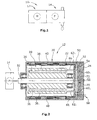
- an electric motor vehicle fluid pump 10 which consists of two modules, namely an electric drive motor 12 and a pump module 14.
- the pump module 14 may be a positive displacement pump, such as a diaphragm pump, rotary vane pump, vane pump or piston pump, but may also be a flow pump , For example, a centrifugal or impeller pump.
- the drive motor 12 is shown in longitudinal section.
- the drive motor 12 is a brushless and electronically commutated drive motor.
- the drive motor 12 has a permanent magnetically excited motor rotor 30 with four rotor poles 38 1 -38 4 , in each of which a permanent magnet 36 is embedded.
- On the stator side six magnetic coils 40 1 -40 6 are provided, which generate a rotating rotor magnetic field.
- the six magnetic coils 40 are fixed in a motor housing 20 which is formed from a housing cup 22 and a housing cover 24.
- the motor rotor 30 has a motor shaft 32 which drives a pump shaft of the pump module 14.
- a printed circuit board 50 lying in a transverse plane, which has a board body 52 with printed conductors 54 on its proximal side.
- the proximal side of the sinker body 52 is the motor rotor 30 axially facing side, whereas the motor rotor 30 axially facing away from the side is the distal side.
- both the control electronics and the power electronics of the motor control are arranged on the proximal side of the board body 52.
- three Hall sensors 60 1 , 60 2 , 60 3 are arranged on the proximal side of the board body, which are arranged approximately in the same radius to Motoraxialen as the permanent magnets 36 of the motor rotor 30th
- the power electronics of the printed circuit board 50 is electrically connected to the magnet coils 40 via the conductor tracks 54 and via axial connecting lines 66.
- Each Hall sensor 60 1 -60 3 is associated with a ferromagnetic axial Feldleitit 62 1 , 62 2 , 62 3 , which is placed proximally on the respective Hall sensor 60 1 , 60 2 , 60 3 .
- the axial field guide pins 62 1 -62 3 have with their proximal longitudinal end only a small distance to the axially opposite end side of the motor rotor 30th
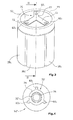
- a star-shaped three-arm sensor closing body 70 is arranged, as in FIG. 3 shown.
- the sensor closing body 70 has three radial arms 72 which extend from the center and extend radially in each case as far as the associated Hall sensors 60 1 -60 3 .
- the sensor closure body 70 is made in one piece from a ferromagnetic material and is glued to the circuit board 50.
- the entire printed circuit board 50 including the control electronics, power electronics and the Hall sensors 60, the Feldleitchane 62 1 -62 3 , the connecting lines 66 and the sensor closing body 70 are cast in a monolithic plastic casting 55.
- the tracks 54 of the board 50 are connected via connecting lines with a motor connector 68.
- FIG. 4 is a second embodiment of a printed circuit board 50 'is shown having a rotor shaft opening 76 through which the rotor shaft 32' protrudes.
- the sensor closing body 70 'therefore has a ring 74 at the edge of the rotor shaft opening 76, from which three relatively short radial arms protrude outwards, which produce the magnetic connection to the three Hall sensors 60 1 -60 3 .
- FIG. 2 is formed by the sensor closing body 70 on the distal side of the Hall sensors 60 1 -60 3 , on the Feldleitchane 62 1 -62 3 proximal to the Hall sensors and the ferromagnetic motor rotor 30 each have a magnetic circuit having only relatively short magnetic gaps, so that overall the total magnetic resistance is low.
- the magnetic fields generated by the rotor permanent magnets 36 therefore have relatively high field strengths in the area of the Hall sensors 60 1 -60 3 .
- there is a high signal / noise ratio at the Hall sensors 60 1 -60 3 which allows a number of structural and conceptual simplifications, which reduce the electrical loss and simplify the production.
Landscapes
- Engineering & Computer Science (AREA)
- Power Engineering (AREA)
- Brushless Motors (AREA)
Abstract
Description
- Die Erfindung bezieht sich auf eine elektrische Kfz-Fluidikpumpe mit einem bürstenlosen und elektronisch kommutierten Antriebsmotor, der für die exakte Detektion der rotatorischen Rotorlage mehrere Hallsensoren aufweist.
- Für einen möglichst sicheren und energieeffizienten Betrieb einer Kfz-Fluidikpumpe, die durch einen elektronisch kommutierten Antriebsmotor angetrieben wird, ist die exakte Detektion der rotatorischen Rotorlage des Motorrotors von großer Bedeutung, da erst hierdurch eine exakte Steuerung und Regelung des Antriebsmotors realisiert werden kann. Hierbei können einerseits unerwünschte Betriebszustände, wie beispielsweise Anlaufprobleme, das sogenannte Toggeln etc. vermieden werden, die insbesondere bei Verdränger- Fluidikpumpen wegen der stark variierenden Drehmomente auftreten können. Zum anderen wird durch eine exakte Terminierung der Stromwendung in den statorseitigen Magnetspulen der absolute Energieverbrauch minimiert.
- Für eine exakte Rotorlage- Detektion werden daher Hallsensoren verwendet, die axial des permanentmagnetisch erregten Motorrotors beispielsweise auf dem Radius der Rotorpole angeordnet sind, und auf diese Weise die von den Rotorpolen generierten vorbeidrehenden Magnetfelder detektieren. Für die Genauigkeit der Rotorlage- Detektion mit den Hallsensoren sind die absolute Feldstärke des durch den betreffenden Hallsensor detektieren Magnetfeldes der Rotorpole sowie die Größe von Störsignalen ausschlaggebend.
- Aufgabe der Erfindung ist es, eine Kfz-Fluidikpumpe mit einem elektronisch kommutierten Antriebsmotor zu schaffen, der eine hohe Betriebssicherheit und Energieeffizienz bei niedrigen Herstellungskosten aufweist.
- Diese Aufgabe wird erfindungsgemäß gelöst mit einer elektrischen Kfz-Fluidikpumpe mit den Merkmalen des Patentanspruchs 1.
- Die erfindungsgemäße Kfz-Fluidikpumpe weist einen bürstenlosen und elektrisch kommutierten Antriebsmotor auf, wobei der permanentmagnetisch erregte Motorrotor mehrere Rotorpole aufweist und statorseitig mehrere Magnetspulen vorgesehen sind. Für die Rotorlage-Detektion sind mindestens zwei statorseitige Hallsensoren vorgesehen, die in einer Querebene zur Motoraxialen liegend angeordnet sind. Die mindestens zwei Sensoren sind beabstandet zur Motoraxialen angeordnet, so dass sie die axialen Magnetfelder der vorbeidrehenden Rotorpole erfassen.
- Es ist ein statischer ferromagnetischer Sensorschlusskörper vorgesehen, der alle zueinander beabstandeten Hallsensoren magnetisch unmittelbar miteinander verbindet. Hierdurch wird der magnetische Kreis für die in axialer Richtung abgestrahlten Magnetfelder der Rotorpole erheblich verbessert, d.h. der magnetische Widerstand in dem Hallsensor-Kreis wird verringert.
- Die dem Motorrotor zugewandte Seite der Hallsensoren weist zu den Rotorpolen in der Regel nur einen relativ kleinen magnetischen Spalt auf. Durch den Sensorschlusskörper wird der magnetische Rückschluss für das Magnetfeld desjenigen Rotorpols, der einem Hallsensor magnetisch in diesem Moment gegenübersteht, erheblich verbessert. Hierdurch wiederum erhöht sich das Signal/Rauschverhältnis an jedem Hallsensor erheblich, so dass die Rotorlage genauer bestimmt werden kann. Hierdurch wiederum können unerwünschte Betriebszustände mit höherer Sicherheit ausgeschlossen werden. An die Qualität der eigentlichen Motorsteuerung und -regelung können umgekehrt geringere Anforderungen gestellt werden, so dass die Motorsteuerung und -regelung im Prinzip einfacher und preiswerter ausfallen kann.
- Alternativ oder ergänzend kann der magnetische Spalt zwischen dem Hallsensor und dem Motorrotor im Prinzip vergrößert werden. Zwar verringert sich hierdurch das absolute Nutzsignal, jedoch können die Hallsensoren räumlich weiter entfernt von den statorseitigen Magnetspulen angeordnet werden, die mit den von Ihnen generierten Magnetfeldern mitunter starke Störquellen für die Hallsensoren darstellen. Mit zunehmender räumlicher Entfernung der Hallsensoren von den statorseitigen Magnetspulen werden diese Störungen erheblich verringert, so dass das Signal/Rauschverhältnis verbessert wird.
- Vorzugsweise ist eine in einer Querebene liegende Leiterbahn-Platine vorgesehen, auf der alle Hallsensoren angeordnet sind. Auf der Leiterbahn-Platine können sich ferner sowohl die Steuerungselektronik und die Leistungselektronik der Motorsteuerung befinden. Die Hallsensoren sind also nicht entfernt von der Platine mit der Steuerungs- und Leistungselektronik angeordnet. Hierdurch sind die Signalwege zwischen den Hallsensor und der Steuerungselektronik kurz. Die Anordnung sowohl der Hallsensoren als auch der Steuerungs- und Leistungselektronik auf einer einzigen Platine wird dadurch erleichtert oder gar erst ermöglicht, dass durch den Sensorschlusskörper das Nutzsignal so stark ist, dass die Hallsensoren nicht in unmittelbarer räumlicher Nähe zu den Rotorpolen angeordnet sein müssen.
- Gemäß einer bevorzugten Ausgestaltung sind die Hallsensoren auf der dem Motorrotor zugewandten proximalen Seite der Leiterbahn-Platine vorgesehen. Die Hallsensoren sind also axial zwischen der Leiterbahn-Platine und dem Motorrotor angeordnet, sind also in räumlich möglichst geringer Entfernung zum Motorrotor platziert.
- Vorzugsweise ist der Sensorschlusskörper auf der dem Motorrotor abgewandten distalen Seite der Leiterbahn-Platine vorgesehen. Dies ist insbesondere dann vorteilhaft, wenn die Hallsensoren auf der gegenüberliegenden proximalen Seite der Leiterbahn-Platine angeordnet sind.
- Gemäß einer bevorzugten Ausgestaltung ist jedem Hallsensor proximal ein im Wesentlichen axial orientierter ferromagnetischer Feldleitstift zugeordnet. Der Hallsensor kann räumlich entfernt bzw. axial beanstandet von dem Motorrotor angeordnet werden, wodurch die Hallsensoren gemeinsam mit der Motorsteuerung auf einer einzigen Leiterbahn-Platine angeordnet sein können. Das proximale Ende des Feldleitstiftes ist dabei jeweils axial möglichst nah an dem Motorrotor vorgesehen. Der Feldleitstift bündelt und leitet das axiale Magnetfeld der Rotorpole relativ verlustarm zu dem jeweiligen Hallsensor. Die ferromagnetischen Feldleitstifte sorgen zusammen mit dem ferromagnetischen Sensorschlusskörper für einen verlustarmen magnetischen Kreis, der jeweils für ein starkes Nutzsignal an den Hallsensoren sorgt. Hierdurch können die Hallsensoren räumlich beanstandet zu den statorseitigen Magnetspulen angeordnet werden, so dass die von den Magnetspulen verursachten Störungen relativ gering sind. Dennoch ist das Nutzsignal so groß, dass die Motorsteuerung bei ausreichender Regelungsgenauigkeit relativ einfach ausgebildet sein kann, wodurch Herstellungskosten eingespart werden können.
- Vorzugsweise ist der Sensorschlusskörper sternförmig ausgebildet und weist mehrere von der Mitte ausgehende Arme auf, nämlich für jeden Hallsensor einen Arm. Alternativ kann die Leiterbahn-Platine eine Rotorwellenöffnung aufweisen, durch die die Rotorwelle des Motorrotors hindurchragt. Der Sensorschlusskörper weist dann an dem Rand der Rotorwellenöffnung einen die Rotorwelle umgebenden Ring auf, ist also nicht sternförmig ausgebildet. Von dem Sensorschlusskörper-Ring können Radialarme nach außen ragen, die die magnetische Verbindung zu den Hallsensoren herstellen. Durch den Sensorschlusskörper-Ring wird ein magnetischer Schluss zu der Rotorwelle hergestellt, die bevorzugt ebenfalls ferromagnetisch ausgebildet ist. Auch durch diese Maßnahme wird der magnetische Schluss zwischen den Hallsensoren einerseits und den Rotorpolen andererseits verbessert.
- Vorzugsweise ist die Leiterbahn-Platine in einen Kunststoff-Gusskörper eingegossen. Hierdurch wird die Leiterbahn-Platine einschließlich aller Hallsensoren und elektronischen Bauteile gut gegen mechanische und andere Störungen abgeschirmt. Ein Vergießen der Leiterbahn-Platine ist jedoch insofern problematisch, als sich hierdurch in der Regel die Kühlung der elektronischen Bauteile und insbesondere der Leistungselektronik bzw. -halbleiter verschlechtert. Da sich durch die Verbesserung des magnetischen Schlusses zwischen den Hallsensoren und den Rotorpolen jedoch die Regelungsgenauigkeit verbessert, und damit die in den Antriebsmotor eingespeiste elektrische Energie verringert wird, verringert sich auch die thermische Verlustleistung insbesondere der Leistungshalbleiter. Hierdurch wird ein Vergießen der Leiterbahn-Platine einschließlich der Leistungshalbleiter in einen Kunststoff-Gusskörper unter Umständen erst ermöglicht,
- Im Folgenden werden zwei Ausführungsbeispiele der Erfindung anhand der Zeichnungen näher erläutert.
- Es zeigen:
-
Figur 1 eine schematische Darstellung einer elektrischen Kfz-Fluidikpumpe mit einem elektrischen Antriebsmotor und einem Pumpenmodul, -
Figur 2 einen Längsschnitt des Antriebsmotors der Kfz-Fluidikpumpe derFigur 1 , -
Figur 3 eine perspektivische Darstellung des Motorrotors und der Leiterbahn-Platine des Antriebsmotors derFigur 2 , und -
Figur 4 ein zweites Ausführungsbeispiel einer Leiterbahn-Platine mit einer zentralen Rotorwellen-Öffnung. - In der
Figur 1 ist schematisch eine elektrische Kfz-Fluidikpumpe 10 dargestellt, die aus zwei Modulen besteht, nämlich einem elektrischen Antriebsmotor 12 und einem Pumpenmodul 14. Das Pumpenmodul 14 kann eine Verdrängerpumpe sein, beispielsweise eine Membranpumpe, Drehschieberpumpe, Flügelzellenpumpe oder Kolbenpumpe, kann jedoch auch eine Strömungspumpe sein, beispielsweise eine Zentrifugal- oder Impeller- Pumpe. - In der
Figur 2 ist der Antriebsmotor 12 im Längsschnitt dargestellt. Der Antriebsmotor 12 ist ein bürstenlose und elektronisch kommutierter Antriebsmotor. Der Antriebsmotor 12 weist einen permanentmagnetisch erregten Motorrotor 30 mit vier Rotorpolen 381-384 auf, in denen jeweils ein Permanentmagnet 36 eingelagert ist. Statorseitig sind sechs Magnetspulen 401-406 vorgesehen, die ein umlaufendes Rotormagnetfeld erzeugen. Die sechs Magnetspulen 40 sind in einem Motorgehäuse 20 fixiert, das aus einem Gehäusebecher 22 und einem Gehäusedeckel 24 gebildet ist. Der Motorrotor 30 weist eine Motorwelle 32 auf, die eine Pumpenwelle des Pumpenmoduls 14 antreibt. - An dem dem Pumpenmodul 14 abgewandten gegenüberliegenden Längsende ist eine in einer Querebene liegende Leiterbahn-Platine 50 vorgesehen, die einen Platinenkörper 52 mit Leiterbahnen 54 auf ihrer proximalen Seite aufweist. Die proximale Seite des Platinenkörpers 52 ist die dem Motorrotor 30 axial zugewandte Seite, wohingegen die dem Motorrotor 30 axial abgewandte Seite die distalen Seite ist. Auf der proximalen Seite des Platinenkörpers 52 sind sowohl die Steuerungselektronik als auch die Leistungselektronik der Motorsteuerung angeordnet. Ferner sind auf der proximalen Seite des Platinenkörpers drei Hallsensoren 601,602,603 angeordnet, die ungefähr in demselben Radius zur Motoraxialen angeordnet sind, wie die Permanentmagnete 36 des Motorrotors 30.
- Die Leistungselektronik der Leiterbahn-Platine 50 ist über die Leiterbahnen 54 und über axiale Verbindungsleitungen 66 elektrisch mit den Magnetspulen 40 verbunden. Jedem Hallsensor 601-603 ist jeweils ein ferromagnetischer axialer Feldleitstift 621,622,623 zugeordnet, der proximal auf den jeweiligen Hallsensor 601,602,603 aufgesetzt ist. Die axialen Feldleitstifte 621-623 haben mit ihrem proximalen Längsende nur einen kleinen Abstand zu der axial gegenüberliegenden Stirnseite des Motorrotors 30.
- Auf der distalen Seite der Leiterbahn-Platine 50 ist ein sternförmiger dreiarmiger Sensorschlusskörper 70 angeordnet, wie in
Figur 3 dargestellt. Der Sensorschlusskörper 70 weist drei von der Mitte ausgehende Radialarme 72 auf, die sich radial jeweils bis zu den zugeordneten Hallsensoren 601-603 erstrecken. Der Sensorschlusskörper 70 ist einstückig aus einem ferromagnetischen Material hergestellt und ist auf die Platine 50 aufgeklebt. - Die gesamte Leiterbahn-Platine 50 einschließlich der Steuerungselektronik, Leistungselektronik und der Hallsensoren 60, die Feldleitstifte 621-623, die Verbindungsleitungen 66 und der Sensorschlusskörper 70 sind in einen monolithischen Kunststoff-Gusskörper 55 eingegossen. Die Leiterbahnen 54 der Platine 50 sind über Anschlussleitungen mit einem Motorstecker 68 verbunden.
- In der
Figur 4 ist ein zweites Ausführungsbeispiel einer Leiterbahn-Platine 50' dargestellt, die eine Rotorwellenöffnung 76 aufweist, durch die die Rotorwelle 32' hindurchragt. Der Sensorschlusskörper 70' weist daher am Rand der Rotorwellenöffnung 76 einen Ring 74 auf, von dem aus drei relativ kurze Radialarme nach außen ragen, die die magnetische Verbindung zu den drei Hallsensoren 601-603 herstellen. - Wie der
Figur 2 entnommen werden kann, wird durch den Sensorschlusskörper 70 auf der distalen Seite der Hallsensoren 601-603, über die Feldleitstifte 621-623 proximal der Hallsensoren und den ferromagnetischen Motorrotor 30 jeweils ein magnetischer Kreis gebildet, der nur relativ kurze Magnetspalte aufweist, so dass insgesamt der magnetische Gesamtwiderstand gering ist. Die von den Rotor-Permanentmagneten 36 generierten Magnetfelder weisen im Bereich der Hallsensoren 601-603 daher relativ hohe Feldstärken auf. Hierdurch liegt an den Hallsensoren 601-603 ein hohes Signal/Rauschverhältnis vor, das eine Reihe von konstruktiven und konzeptionellen Vereinfachungen ermöglicht, die die elektrische Verlustleitung verringern und die Herstellung vereinfachen.
Claims (8)
- Elektrische Kfz-Fluidikpumpe (10) mit einem elektrischen Antriebsmotor (12), der bürstenlos und elektronisch kommutiert ist, wobei der Antriebsmotor (12) aufweist:einen permanentmagnetischen Motorrotor (30) mit mehreren Rotorpolen (381-384),mehrere statorseitige Magnetspulen (40),mindestens zwei statorseitige Hallsensoren (601,602,603), die in einer Querebene liegend exzentrisch derart angeordnet sind, dass sie die axialen Magnetfelder der Rotorpole (381-384) erfassen,wobei statorseitig ein ferromagnetischer Sensorschlusskörper (70) vorgesehen ist, der die zueinander beanstandet angeordneten Hallsensoren (601,602,603) magnetisch unmittelbar miteinander verbindet.
- Elektrische Kfz-Fluidikpumpe (10) nach Anspruch 1, wobei eine in einer Querebene liegende Leiterbahn-Platine (50) vorgesehen ist, auf der die Hallsensoren (601,602,603) angeordnet sind.
- Elektrische Kfz-Fluidikpumpe (10) nach Anspruch 2, wobei die Hallsensoren (601,602,603) auf der dem Motorrotor (30) axial zugewandten proximalen Seite der Leiterbahn-Platine (50) vorgesehen sind.
- Elektrische Kfz-Fluidikpumpe (10) nach einem der vorangegangenen Ansprüche, wobei der Sensorschlusskörper (70) auf der der Leiterbahn-Platine (50) axial abgewandten distalen Seite der Leiterbahn-Platine (50) vorgesehen ist.
- Elektrische Kfz-Fluidikpumpe (10) nach einem der vorangegangenen Ansprüche, wobei jedem Hallsensor (601,602,603) proximal ein im Wesentlichen axial orientierter Feldleitstift (621,622,623) zugeordnet ist.
- Elektrische Kfz-Fluidikpumpe (10) nach einem der vorangegangenen Ansprüche, wobei der Sensorschlusskörper (70) sternförmig ausgebildet ist und mehrere von der Mitte ausgehende Radialarme (72) aufweist, die jeweils einem Hallsensor (60) zugeordnet sind.
- Elektrische Kfz-Fluidikpumpe (10) nach einem der Ansprüche 1-5, wobei die Leiterbahn-Platine (50) eine Rotorwellenöffnung (76) aufweist, durch die eine Rotorwelle (32') hindurchragt, wobei der Sensorschlusskörper (70') einen die Rotorwelle (32') umgebenden Ring (74) aufweist.
- Elektrische Kfz-Fluidikpumpe (10) nach einem der Ansprüche 2-6, wobei die Leiterbahn-Platine (50) in einen Kunststoff-Gusskörper (55) eingegossen ist.
Priority Applications (1)
| Application Number | Priority Date | Filing Date | Title |
|---|---|---|---|
| EP12181204.4A EP2701291B1 (de) | 2012-08-21 | 2012-08-21 | Elektrische Kfz-Fluidikpumpe |
Applications Claiming Priority (1)
| Application Number | Priority Date | Filing Date | Title |
|---|---|---|---|
| EP12181204.4A EP2701291B1 (de) | 2012-08-21 | 2012-08-21 | Elektrische Kfz-Fluidikpumpe |
Publications (2)
| Publication Number | Publication Date |
|---|---|
| EP2701291A1 true EP2701291A1 (de) | 2014-02-26 |
| EP2701291B1 EP2701291B1 (de) | 2015-08-12 |
Family
ID=46800034
Family Applications (1)
| Application Number | Title | Priority Date | Filing Date |
|---|---|---|---|
| EP12181204.4A Active EP2701291B1 (de) | 2012-08-21 | 2012-08-21 | Elektrische Kfz-Fluidikpumpe |
Country Status (1)
| Country | Link |
|---|---|
| EP (1) | EP2701291B1 (de) |
Cited By (4)
| Publication number | Priority date | Publication date | Assignee | Title |
|---|---|---|---|---|
| WO2017121472A1 (en) * | 2016-01-13 | 2017-07-20 | Pierburg Pump Technology Gmbh | Automotive electric fluidic pump |
| WO2018229137A1 (de) * | 2017-06-13 | 2018-12-20 | KNF Micro AG | Membranpumpe |
| WO2019081011A1 (de) * | 2017-10-25 | 2019-05-02 | Pierburg Pump Technology Gmbh | Elektrische kfz-fluidpumpe |
| WO2022228623A1 (de) * | 2021-04-27 | 2022-11-03 | Bühler Motor GmbH | Verfahren zum anlaufen eines rotors eines klauenpolmotors |
Families Citing this family (1)
| Publication number | Priority date | Publication date | Assignee | Title |
|---|---|---|---|---|
| JP6304175B2 (ja) * | 2015-08-19 | 2018-04-04 | 株式会社デンソー | 電動機 |
Citations (4)
| Publication number | Priority date | Publication date | Assignee | Title |
|---|---|---|---|---|
| DE2918329A1 (de) * | 1979-05-07 | 1980-12-04 | Papst Motoren Kg | Verfahren zum befestigen eines galvanomagnetischen sensors in einer ausnehmung einer leiterplatte |
| DE3434965A1 (de) * | 1983-09-22 | 1985-04-04 | Papst-Motoren GmbH & Co KG, 7742 St Georgen | Gekapselter kleinstmotor |
| JPH10311290A (ja) * | 1997-05-13 | 1998-11-24 | Japan Servo Co Ltd | キャンドモータポンプとその製造方法 |
| EP1146625A2 (de) * | 2000-04-10 | 2001-10-17 | Kabushiki Kaisha MORIC | Rotierende elektrische Maschine |
-
2012
- 2012-08-21 EP EP12181204.4A patent/EP2701291B1/de active Active
Patent Citations (4)
| Publication number | Priority date | Publication date | Assignee | Title |
|---|---|---|---|---|
| DE2918329A1 (de) * | 1979-05-07 | 1980-12-04 | Papst Motoren Kg | Verfahren zum befestigen eines galvanomagnetischen sensors in einer ausnehmung einer leiterplatte |
| DE3434965A1 (de) * | 1983-09-22 | 1985-04-04 | Papst-Motoren GmbH & Co KG, 7742 St Georgen | Gekapselter kleinstmotor |
| JPH10311290A (ja) * | 1997-05-13 | 1998-11-24 | Japan Servo Co Ltd | キャンドモータポンプとその製造方法 |
| EP1146625A2 (de) * | 2000-04-10 | 2001-10-17 | Kabushiki Kaisha MORIC | Rotierende elektrische Maschine |
Cited By (12)
| Publication number | Priority date | Publication date | Assignee | Title |
|---|---|---|---|---|
| WO2017121472A1 (en) * | 2016-01-13 | 2017-07-20 | Pierburg Pump Technology Gmbh | Automotive electric fluidic pump |
| CN109075687A (zh) * | 2016-01-13 | 2018-12-21 | 皮尔伯格泵技术有限责任公司 | 汽车电动流体泵 |
| JP2019501618A (ja) * | 2016-01-13 | 2019-01-17 | ピアーブルグ パンプ テクノロジー ゲゼルシャフト ミット ベシュレンクテル ハフツングPierburg Pump Technology GmbH | 自動車用電動式流体ポンプ |
| CN109075687B (zh) * | 2016-01-13 | 2020-12-15 | 皮尔伯格泵技术有限责任公司 | 汽车电动流体泵 |
| US11005351B2 (en) | 2016-01-13 | 2021-05-11 | Pierburg Pump Technology Gmbh | Automotive electric fluidic pump |
| WO2018229137A1 (de) * | 2017-06-13 | 2018-12-20 | KNF Micro AG | Membranpumpe |
| WO2019081011A1 (de) * | 2017-10-25 | 2019-05-02 | Pierburg Pump Technology Gmbh | Elektrische kfz-fluidpumpe |
| CN111226384A (zh) * | 2017-10-25 | 2020-06-02 | 皮尔伯格泵技术有限责任公司 | 电气的机动车流体泵 |
| CN111226384B (zh) * | 2017-10-25 | 2022-07-05 | 皮尔伯格泵技术有限责任公司 | 电气的机动车流体泵 |
| US11462971B2 (en) | 2017-10-25 | 2022-10-04 | Pierburg Pump Technology Gmbh | Electric fluid pump for a motor vehicle |
| WO2022228623A1 (de) * | 2021-04-27 | 2022-11-03 | Bühler Motor GmbH | Verfahren zum anlaufen eines rotors eines klauenpolmotors |
| US12609641B2 (en) | 2021-04-27 | 2026-04-21 | Bühler Motor GmbH | Method for starting a rotor of a claw pole motor |
Also Published As
| Publication number | Publication date |
|---|---|
| EP2701291B1 (de) | 2015-08-12 |
Similar Documents
| Publication | Publication Date | Title |
|---|---|---|
| EP2701291B1 (de) | Elektrische Kfz-Fluidikpumpe | |
| EP1076924B1 (de) | Senkrechter hallsensor und bürstenloser elektromotor mit einem senkrechten hallsensor | |
| EP2584672B1 (de) | Gehäuseteil für eine elektrische Maschine | |
| EP1865202B1 (de) | Wasserpumpe für Teiche, Aquarien, Springbrunnen und dergleichen | |
| DE102017104624A1 (de) | Ständer, Motor mit demselben und Verfahren zum Herstellen desselben | |
| DE102011002007A1 (de) | Motorisierte Gerätschaft | |
| DE102011056920A1 (de) | Steuerung | |
| DE112017000172T5 (de) | Bürstenloser Gleichstrommotor | |
| EP2476914A1 (de) | Elektrische Kfz-Kühlmittelpumpe | |
| DE102017210426B4 (de) | Pumpe, insbesondere Getriebeölpumpe | |
| WO2015067497A2 (de) | Elektromaschine | |
| EP0374805B1 (de) | Elektronisch kommutierter Synchronmotorantrieb | |
| EP2450575A1 (de) | Elektromotorische Kfz-Flüssigkeits-Förderpumpe | |
| DE102004059181A1 (de) | Maschine mit integriertem Drehgeber | |
| WO2021121897A1 (de) | Ventilvorrichtung | |
| DE102015115153A1 (de) | Bürstenloser Gleichstrommotor mit integrierter elektronischer Schaltung | |
| WO2019081011A9 (de) | Elektrische kfz-fluidpumpe | |
| DE102016102681A1 (de) | Elektrische Wasserpumpe | |
| DE102007021917A1 (de) | Elektrische Maschine mit verbesserter Wärmeabfuhr | |
| EP2348618A2 (de) | Aktuator | |
| EP2704299A1 (de) | Elektromotorische Kfz-Flüssigkeits-Förderpumpe | |
| EP3403320B1 (de) | Fluidpumpe für ein elektrisches automobil | |
| DE102008009018B4 (de) | Elektromotor | |
| EP2060793A2 (de) | Vakuumpumpe | |
| DE102008010913A1 (de) | Elektromotor |
Legal Events
| Date | Code | Title | Description |
|---|---|---|---|
| PUAI | Public reference made under article 153(3) epc to a published international application that has entered the european phase |
Free format text: ORIGINAL CODE: 0009012 |
|
| AK | Designated contracting states |
Kind code of ref document: A1 Designated state(s): AL AT BE BG CH CY CZ DE DK EE ES FI FR GB GR HR HU IE IS IT LI LT LU LV MC MK MT NL NO PL PT RO RS SE SI SK SM TR |
|
| AX | Request for extension of the european patent |
Extension state: BA ME |
|
| 17P | Request for examination filed |
Effective date: 20140826 |
|
| RBV | Designated contracting states (corrected) |
Designated state(s): AL AT BE BG CH CY CZ DE DK EE ES FI FR GB GR HR HU IE IS IT LI LT LU LV MC MK MT NL NO PL PT RO RS SE SI SK SM TR |
|
| 17Q | First examination report despatched |
Effective date: 20141014 |
|
| GRAP | Despatch of communication of intention to grant a patent |
Free format text: ORIGINAL CODE: EPIDOSNIGR1 |
|
| INTG | Intention to grant announced |
Effective date: 20150427 |
|
| GRAS | Grant fee paid |
Free format text: ORIGINAL CODE: EPIDOSNIGR3 |
|
| GRAA | (expected) grant |
Free format text: ORIGINAL CODE: 0009210 |
|
| AK | Designated contracting states |
Kind code of ref document: B1 Designated state(s): AL AT BE BG CH CY CZ DE DK EE ES FI FR GB GR HR HU IE IS IT LI LT LU LV MC MK MT NL NO PL PT RO RS SE SI SK SM TR |
|
| REG | Reference to a national code |
Ref country code: GB Ref legal event code: FG4D Free format text: NOT ENGLISH |
|
| REG | Reference to a national code |
Ref country code: CH Ref legal event code: EP |
|
| REG | Reference to a national code |
Ref country code: AT Ref legal event code: REF Ref document number: 742910 Country of ref document: AT Kind code of ref document: T Effective date: 20150815 |
|
| REG | Reference to a national code |
Ref country code: IE Ref legal event code: FG4D Free format text: LANGUAGE OF EP DOCUMENT: GERMAN |
|
| REG | Reference to a national code |
Ref country code: DE Ref legal event code: R096 Ref document number: 502012004083 Country of ref document: DE |
|
| REG | Reference to a national code |
Ref country code: LT Ref legal event code: MG4D |
|
| REG | Reference to a national code |
Ref country code: NL Ref legal event code: MP Effective date: 20150812 |
|
| PG25 | Lapsed in a contracting state [announced via postgrant information from national office to epo] |
Ref country code: NO Free format text: LAPSE BECAUSE OF FAILURE TO SUBMIT A TRANSLATION OF THE DESCRIPTION OR TO PAY THE FEE WITHIN THE PRESCRIBED TIME-LIMIT Effective date: 20151112 Ref country code: LT Free format text: LAPSE BECAUSE OF FAILURE TO SUBMIT A TRANSLATION OF THE DESCRIPTION OR TO PAY THE FEE WITHIN THE PRESCRIBED TIME-LIMIT Effective date: 20150812 Ref country code: LV Free format text: LAPSE BECAUSE OF FAILURE TO SUBMIT A TRANSLATION OF THE DESCRIPTION OR TO PAY THE FEE WITHIN THE PRESCRIBED TIME-LIMIT Effective date: 20150812 Ref country code: FI Free format text: LAPSE BECAUSE OF FAILURE TO SUBMIT A TRANSLATION OF THE DESCRIPTION OR TO PAY THE FEE WITHIN THE PRESCRIBED TIME-LIMIT Effective date: 20150812 Ref country code: GR Free format text: LAPSE BECAUSE OF FAILURE TO SUBMIT A TRANSLATION OF THE DESCRIPTION OR TO PAY THE FEE WITHIN THE PRESCRIBED TIME-LIMIT Effective date: 20151113 |
|
| PG25 | Lapsed in a contracting state [announced via postgrant information from national office to epo] |
Ref country code: IS Free format text: LAPSE BECAUSE OF FAILURE TO SUBMIT A TRANSLATION OF THE DESCRIPTION OR TO PAY THE FEE WITHIN THE PRESCRIBED TIME-LIMIT Effective date: 20151212 Ref country code: SE Free format text: LAPSE BECAUSE OF FAILURE TO SUBMIT A TRANSLATION OF THE DESCRIPTION OR TO PAY THE FEE WITHIN THE PRESCRIBED TIME-LIMIT Effective date: 20150812 Ref country code: RS Free format text: LAPSE BECAUSE OF FAILURE TO SUBMIT A TRANSLATION OF THE DESCRIPTION OR TO PAY THE FEE WITHIN THE PRESCRIBED TIME-LIMIT Effective date: 20150812 Ref country code: PT Free format text: LAPSE BECAUSE OF FAILURE TO SUBMIT A TRANSLATION OF THE DESCRIPTION OR TO PAY THE FEE WITHIN THE PRESCRIBED TIME-LIMIT Effective date: 20151214 Ref country code: PL Free format text: LAPSE BECAUSE OF FAILURE TO SUBMIT A TRANSLATION OF THE DESCRIPTION OR TO PAY THE FEE WITHIN THE PRESCRIBED TIME-LIMIT Effective date: 20150812 Ref country code: HR Free format text: LAPSE BECAUSE OF FAILURE TO SUBMIT A TRANSLATION OF THE DESCRIPTION OR TO PAY THE FEE WITHIN THE PRESCRIBED TIME-LIMIT Effective date: 20150812 Ref country code: ES Free format text: LAPSE BECAUSE OF FAILURE TO SUBMIT A TRANSLATION OF THE DESCRIPTION OR TO PAY THE FEE WITHIN THE PRESCRIBED TIME-LIMIT Effective date: 20150812 |
|
| PG25 | Lapsed in a contracting state [announced via postgrant information from national office to epo] |
Ref country code: NL Free format text: LAPSE BECAUSE OF FAILURE TO SUBMIT A TRANSLATION OF THE DESCRIPTION OR TO PAY THE FEE WITHIN THE PRESCRIBED TIME-LIMIT Effective date: 20150812 |
|
| REG | Reference to a national code |
Ref country code: CH Ref legal event code: PL |
|
| PG25 | Lapsed in a contracting state [announced via postgrant information from national office to epo] |
Ref country code: DK Free format text: LAPSE BECAUSE OF FAILURE TO SUBMIT A TRANSLATION OF THE DESCRIPTION OR TO PAY THE FEE WITHIN THE PRESCRIBED TIME-LIMIT Effective date: 20150812 Ref country code: LI Free format text: LAPSE BECAUSE OF NON-PAYMENT OF DUE FEES Effective date: 20150831 Ref country code: EE Free format text: LAPSE BECAUSE OF FAILURE TO SUBMIT A TRANSLATION OF THE DESCRIPTION OR TO PAY THE FEE WITHIN THE PRESCRIBED TIME-LIMIT Effective date: 20150812 Ref country code: SK Free format text: LAPSE BECAUSE OF FAILURE TO SUBMIT A TRANSLATION OF THE DESCRIPTION OR TO PAY THE FEE WITHIN THE PRESCRIBED TIME-LIMIT Effective date: 20150812 Ref country code: CZ Free format text: LAPSE BECAUSE OF FAILURE TO SUBMIT A TRANSLATION OF THE DESCRIPTION OR TO PAY THE FEE WITHIN THE PRESCRIBED TIME-LIMIT Effective date: 20150812 Ref country code: CH Free format text: LAPSE BECAUSE OF NON-PAYMENT OF DUE FEES Effective date: 20150831 |
|
| REG | Reference to a national code |
Ref country code: DE Ref legal event code: R097 Ref document number: 502012004083 Country of ref document: DE |
|
| PG25 | Lapsed in a contracting state [announced via postgrant information from national office to epo] |
Ref country code: RO Free format text: LAPSE BECAUSE OF FAILURE TO SUBMIT A TRANSLATION OF THE DESCRIPTION OR TO PAY THE FEE WITHIN THE PRESCRIBED TIME-LIMIT Effective date: 20150812 Ref country code: MC Free format text: LAPSE BECAUSE OF FAILURE TO SUBMIT A TRANSLATION OF THE DESCRIPTION OR TO PAY THE FEE WITHIN THE PRESCRIBED TIME-LIMIT Effective date: 20150812 |
|
| REG | Reference to a national code |
Ref country code: IE Ref legal event code: MM4A |
|
| PLBE | No opposition filed within time limit |
Free format text: ORIGINAL CODE: 0009261 |
|
| STAA | Information on the status of an ep patent application or granted ep patent |
Free format text: STATUS: NO OPPOSITION FILED WITHIN TIME LIMIT |
|
| 26N | No opposition filed |
Effective date: 20160513 |
|
| PG25 | Lapsed in a contracting state [announced via postgrant information from national office to epo] |
Ref country code: IE Free format text: LAPSE BECAUSE OF NON-PAYMENT OF DUE FEES Effective date: 20150821 |
|
| REG | Reference to a national code |
Ref country code: FR Ref legal event code: PLFP Year of fee payment: 5 |
|
| PG25 | Lapsed in a contracting state [announced via postgrant information from national office to epo] |
Ref country code: SI Free format text: LAPSE BECAUSE OF FAILURE TO SUBMIT A TRANSLATION OF THE DESCRIPTION OR TO PAY THE FEE WITHIN THE PRESCRIBED TIME-LIMIT Effective date: 20150812 |
|
| PG25 | Lapsed in a contracting state [announced via postgrant information from national office to epo] |
Ref country code: MT Free format text: LAPSE BECAUSE OF FAILURE TO SUBMIT A TRANSLATION OF THE DESCRIPTION OR TO PAY THE FEE WITHIN THE PRESCRIBED TIME-LIMIT Effective date: 20150812 |
|
| GBPC | Gb: european patent ceased through non-payment of renewal fee |
Effective date: 20160821 |
|
| PG25 | Lapsed in a contracting state [announced via postgrant information from national office to epo] |
Ref country code: SM Free format text: LAPSE BECAUSE OF FAILURE TO SUBMIT A TRANSLATION OF THE DESCRIPTION OR TO PAY THE FEE WITHIN THE PRESCRIBED TIME-LIMIT Effective date: 20150812 Ref country code: HU Free format text: LAPSE BECAUSE OF FAILURE TO SUBMIT A TRANSLATION OF THE DESCRIPTION OR TO PAY THE FEE WITHIN THE PRESCRIBED TIME-LIMIT; INVALID AB INITIO Effective date: 20120821 Ref country code: BG Free format text: LAPSE BECAUSE OF FAILURE TO SUBMIT A TRANSLATION OF THE DESCRIPTION OR TO PAY THE FEE WITHIN THE PRESCRIBED TIME-LIMIT Effective date: 20150812 |
|
| PG25 | Lapsed in a contracting state [announced via postgrant information from national office to epo] |
Ref country code: CY Free format text: LAPSE BECAUSE OF FAILURE TO SUBMIT A TRANSLATION OF THE DESCRIPTION OR TO PAY THE FEE WITHIN THE PRESCRIBED TIME-LIMIT Effective date: 20150812 |
|
| PG25 | Lapsed in a contracting state [announced via postgrant information from national office to epo] |
Ref country code: BE Free format text: LAPSE BECAUSE OF NON-PAYMENT OF DUE FEES Effective date: 20150831 Ref country code: GB Free format text: LAPSE BECAUSE OF NON-PAYMENT OF DUE FEES Effective date: 20160821 |
|
| REG | Reference to a national code |
Ref country code: FR Ref legal event code: PLFP Year of fee payment: 6 |
|
| PG25 | Lapsed in a contracting state [announced via postgrant information from national office to epo] |
Ref country code: LU Free format text: LAPSE BECAUSE OF NON-PAYMENT OF DUE FEES Effective date: 20150821 |
|
| PG25 | Lapsed in a contracting state [announced via postgrant information from national office to epo] |
Ref country code: MK Free format text: LAPSE BECAUSE OF FAILURE TO SUBMIT A TRANSLATION OF THE DESCRIPTION OR TO PAY THE FEE WITHIN THE PRESCRIBED TIME-LIMIT Effective date: 20150812 Ref country code: TR Free format text: LAPSE BECAUSE OF FAILURE TO SUBMIT A TRANSLATION OF THE DESCRIPTION OR TO PAY THE FEE WITHIN THE PRESCRIBED TIME-LIMIT Effective date: 20150812 |
|
| REG | Reference to a national code |
Ref country code: FR Ref legal event code: PLFP Year of fee payment: 7 |
|
| REG | Reference to a national code |
Ref country code: AT Ref legal event code: MM01 Ref document number: 742910 Country of ref document: AT Kind code of ref document: T Effective date: 20170821 |
|
| PG25 | Lapsed in a contracting state [announced via postgrant information from national office to epo] |
Ref country code: AL Free format text: LAPSE BECAUSE OF FAILURE TO SUBMIT A TRANSLATION OF THE DESCRIPTION OR TO PAY THE FEE WITHIN THE PRESCRIBED TIME-LIMIT Effective date: 20150812 |
|
| PG25 | Lapsed in a contracting state [announced via postgrant information from national office to epo] |
Ref country code: AT Free format text: LAPSE BECAUSE OF NON-PAYMENT OF DUE FEES Effective date: 20170821 |
|
| REG | Reference to a national code |
Ref country code: DE Ref legal event code: R082 Ref document number: 502012004083 Country of ref document: DE Representative=s name: TERPATENT PARTGMBB, DE Ref country code: DE Ref legal event code: R082 Ref document number: 502012004083 Country of ref document: DE Representative=s name: TERPATENT PATENTANWAELTE TER SMITTEN EBERLEIN-, DE |
|
| PGFP | Annual fee paid to national office [announced via postgrant information from national office to epo] |
Ref country code: DE Payment date: 20240819 Year of fee payment: 13 |
|
| PGFP | Annual fee paid to national office [announced via postgrant information from national office to epo] |
Ref country code: FR Payment date: 20240821 Year of fee payment: 13 |
|
| PGFP | Annual fee paid to national office [announced via postgrant information from national office to epo] |
Ref country code: IT Payment date: 20240830 Year of fee payment: 13 |
|
| REG | Reference to a national code |
Ref country code: DE Ref legal event code: R119 Ref document number: 502012004083 Country of ref document: DE |