EP2700924B1 - High temperature resistive temperature detector for exhaust gas temperature measurement - Google Patents
High temperature resistive temperature detector for exhaust gas temperature measurement Download PDFInfo
- Publication number
- EP2700924B1 EP2700924B1 EP13180543.4A EP13180543A EP2700924B1 EP 2700924 B1 EP2700924 B1 EP 2700924B1 EP 13180543 A EP13180543 A EP 13180543A EP 2700924 B1 EP2700924 B1 EP 2700924B1
- Authority
- EP
- European Patent Office
- Prior art keywords
- resistive
- temperature detector
- resistive element
- leads
- insulating carrier
- Prior art date
- Legal status (The legal status is an assumption and is not a legal conclusion. Google has not performed a legal analysis and makes no representation as to the accuracy of the status listed.)
- Not-in-force
Links
- 238000009529 body temperature measurement Methods 0.000 title description 4
- BASFCYQUMIYNBI-UHFFFAOYSA-N platinum Chemical compound [Pt] BASFCYQUMIYNBI-UHFFFAOYSA-N 0.000 claims description 34
- 239000000463 material Substances 0.000 claims description 26
- 229910052697 platinum Inorganic materials 0.000 claims description 16
- 238000004891 communication Methods 0.000 claims description 10
- MCMNRKCIXSYSNV-UHFFFAOYSA-N Zirconium dioxide Chemical compound O=[Zr]=O MCMNRKCIXSYSNV-UHFFFAOYSA-N 0.000 claims description 8
- 239000011521 glass Substances 0.000 claims description 6
- 239000000843 powder Substances 0.000 claims description 5
- 239000000919 ceramic Substances 0.000 claims description 4
- DECCZIUVGMLHKQ-UHFFFAOYSA-N rhenium tungsten Chemical compound [W].[Re] DECCZIUVGMLHKQ-UHFFFAOYSA-N 0.000 claims description 4
- 238000000034 method Methods 0.000 description 17
- 239000007789 gas Substances 0.000 description 14
- WFKWXMTUELFFGS-UHFFFAOYSA-N tungsten Chemical compound [W] WFKWXMTUELFFGS-UHFFFAOYSA-N 0.000 description 12
- 229910052721 tungsten Inorganic materials 0.000 description 11
- 239000010937 tungsten Substances 0.000 description 11
- 239000000567 combustion gas Substances 0.000 description 10
- 239000010410 layer Substances 0.000 description 9
- 238000010276 construction Methods 0.000 description 8
- 239000000758 substrate Substances 0.000 description 8
- 239000003570 air Substances 0.000 description 6
- 239000010408 film Substances 0.000 description 6
- 238000009413 insulation Methods 0.000 description 6
- 229910052702 rhenium Inorganic materials 0.000 description 6
- WUAPFZMCVAUBPE-UHFFFAOYSA-N rhenium atom Chemical compound [Re] WUAPFZMCVAUBPE-UHFFFAOYSA-N 0.000 description 6
- 239000010409 thin film Substances 0.000 description 6
- 239000011810 insulating material Substances 0.000 description 5
- 239000000523 sample Substances 0.000 description 5
- 238000013461 design Methods 0.000 description 4
- 230000006870 function Effects 0.000 description 4
- 230000000670 limiting effect Effects 0.000 description 4
- 229910052751 metal Inorganic materials 0.000 description 4
- 239000002184 metal Substances 0.000 description 4
- 150000002739 metals Chemical class 0.000 description 4
- 238000012986 modification Methods 0.000 description 4
- 230000004048 modification Effects 0.000 description 4
- 230000001590 oxidative effect Effects 0.000 description 4
- 230000008569 process Effects 0.000 description 4
- CPLXHLVBOLITMK-UHFFFAOYSA-N Magnesium oxide Chemical compound [Mg]=O CPLXHLVBOLITMK-UHFFFAOYSA-N 0.000 description 3
- 229910001260 Pt alloy Inorganic materials 0.000 description 3
- 229910000691 Re alloy Inorganic materials 0.000 description 3
- 229910045601 alloy Inorganic materials 0.000 description 3
- 239000000956 alloy Substances 0.000 description 3
- 238000000576 coating method Methods 0.000 description 3
- 238000004590 computer program Methods 0.000 description 3
- 239000000446 fuel Substances 0.000 description 3
- WABPQHHGFIMREM-UHFFFAOYSA-N lead(0) Chemical compound [Pb] WABPQHHGFIMREM-UHFFFAOYSA-N 0.000 description 3
- 238000005259 measurement Methods 0.000 description 3
- 229910052703 rhodium Inorganic materials 0.000 description 3
- 239000010948 rhodium Substances 0.000 description 3
- MHOVAHRLVXNVSD-UHFFFAOYSA-N rhodium atom Chemical compound [Rh] MHOVAHRLVXNVSD-UHFFFAOYSA-N 0.000 description 3
- XKRFYHLGVUSROY-UHFFFAOYSA-N Argon Chemical compound [Ar] XKRFYHLGVUSROY-UHFFFAOYSA-N 0.000 description 2
- IJGRMHOSHXDMSA-UHFFFAOYSA-N Atomic nitrogen Chemical compound N#N IJGRMHOSHXDMSA-UHFFFAOYSA-N 0.000 description 2
- ZOKXTWBITQBERF-UHFFFAOYSA-N Molybdenum Chemical compound [Mo] ZOKXTWBITQBERF-UHFFFAOYSA-N 0.000 description 2
- 230000000712 assembly Effects 0.000 description 2
- 238000000429 assembly Methods 0.000 description 2
- QVGXLLKOCUKJST-UHFFFAOYSA-N atomic oxygen Chemical compound [O] QVGXLLKOCUKJST-UHFFFAOYSA-N 0.000 description 2
- 239000011248 coating agent Substances 0.000 description 2
- 230000006835 compression Effects 0.000 description 2
- 238000007906 compression Methods 0.000 description 2
- 239000011261 inert gas Substances 0.000 description 2
- 239000000395 magnesium oxide Substances 0.000 description 2
- 238000004519 manufacturing process Methods 0.000 description 2
- 229910052750 molybdenum Inorganic materials 0.000 description 2
- 239000011733 molybdenum Substances 0.000 description 2
- 230000003647 oxidation Effects 0.000 description 2
- 238000007254 oxidation reaction Methods 0.000 description 2
- 239000001301 oxygen Substances 0.000 description 2
- 229910052760 oxygen Inorganic materials 0.000 description 2
- 230000002829 reductive effect Effects 0.000 description 2
- 238000007789 sealing Methods 0.000 description 2
- PNEYBMLMFCGWSK-UHFFFAOYSA-N aluminium oxide Inorganic materials [O-2].[O-2].[O-2].[Al+3].[Al+3] PNEYBMLMFCGWSK-UHFFFAOYSA-N 0.000 description 1
- 239000012080 ambient air Substances 0.000 description 1
- 230000003064 anti-oxidating effect Effects 0.000 description 1
- 229910052786 argon Inorganic materials 0.000 description 1
- 238000009835 boiling Methods 0.000 description 1
- 230000015556 catabolic process Effects 0.000 description 1
- 230000008859 change Effects 0.000 description 1
- 238000002485 combustion reaction Methods 0.000 description 1
- 239000004020 conductor Substances 0.000 description 1
- 230000008602 contraction Effects 0.000 description 1
- 238000005520 cutting process Methods 0.000 description 1
- 230000007423 decrease Effects 0.000 description 1
- 230000003247 decreasing effect Effects 0.000 description 1
- 238000006731 degradation reaction Methods 0.000 description 1
- 230000001934 delay Effects 0.000 description 1
- 230000001419 dependent effect Effects 0.000 description 1
- 230000000694 effects Effects 0.000 description 1
- 238000009791 electrochemical migration reaction Methods 0.000 description 1
- 230000008030 elimination Effects 0.000 description 1
- 238000003379 elimination reaction Methods 0.000 description 1
- 230000005284 excitation Effects 0.000 description 1
- 239000000284 extract Substances 0.000 description 1
- 238000000605 extraction Methods 0.000 description 1
- 238000013213 extrapolation Methods 0.000 description 1
- 229910052735 hafnium Inorganic materials 0.000 description 1
- VBJZVLUMGGDVMO-UHFFFAOYSA-N hafnium atom Chemical compound [Hf] VBJZVLUMGGDVMO-UHFFFAOYSA-N 0.000 description 1
- 230000002401 inhibitory effect Effects 0.000 description 1
- 238000005304 joining Methods 0.000 description 1
- 238000010030 laminating Methods 0.000 description 1
- 239000007788 liquid Substances 0.000 description 1
- AXZKOIWUVFPNLO-UHFFFAOYSA-N magnesium;oxygen(2-) Chemical compound [O-2].[Mg+2] AXZKOIWUVFPNLO-UHFFFAOYSA-N 0.000 description 1
- 239000000203 mixture Substances 0.000 description 1
- 230000007935 neutral effect Effects 0.000 description 1
- 229910052757 nitrogen Inorganic materials 0.000 description 1
- 230000003287 optical effect Effects 0.000 description 1
- 238000005457 optimization Methods 0.000 description 1
- 229910001175 oxide dispersion-strengthened alloy Inorganic materials 0.000 description 1
- TWNQGVIAIRXVLR-UHFFFAOYSA-N oxo(oxoalumanyloxy)alumane Chemical compound O=[Al]O[Al]=O TWNQGVIAIRXVLR-UHFFFAOYSA-N 0.000 description 1
- 229920001296 polysiloxane Polymers 0.000 description 1
- 238000010248 power generation Methods 0.000 description 1
- 238000012545 processing Methods 0.000 description 1
- 238000012827 research and development Methods 0.000 description 1
- 230000004044 response Effects 0.000 description 1
- 239000005394 sealing glass Substances 0.000 description 1
- 239000004065 semiconductor Substances 0.000 description 1
- 239000002356 single layer Substances 0.000 description 1
- 238000005245 sintering Methods 0.000 description 1
- 230000000087 stabilizing effect Effects 0.000 description 1
- 239000010935 stainless steel Substances 0.000 description 1
- 229910001220 stainless steel Inorganic materials 0.000 description 1
- 230000003068 static effect Effects 0.000 description 1
- 238000003860 storage Methods 0.000 description 1
- 229910052715 tantalum Inorganic materials 0.000 description 1
- GUVRBAGPIYLISA-UHFFFAOYSA-N tantalum atom Chemical compound [Ta] GUVRBAGPIYLISA-UHFFFAOYSA-N 0.000 description 1
- 230000007704 transition Effects 0.000 description 1
- 238000009966 trimming Methods 0.000 description 1
- 238000011144 upstream manufacturing Methods 0.000 description 1
- 238000007740 vapor deposition Methods 0.000 description 1
Images




Classifications
-
- G—PHYSICS
- G01—MEASURING; TESTING
- G01K—MEASURING TEMPERATURE; MEASURING QUANTITY OF HEAT; THERMALLY-SENSITIVE ELEMENTS NOT OTHERWISE PROVIDED FOR
- G01K7/00—Measuring temperature based on the use of electric or magnetic elements directly sensitive to heat ; Power supply therefor, e.g. using thermoelectric elements
- G01K7/16—Measuring temperature based on the use of electric or magnetic elements directly sensitive to heat ; Power supply therefor, e.g. using thermoelectric elements using resistive elements
- G01K7/18—Measuring temperature based on the use of electric or magnetic elements directly sensitive to heat ; Power supply therefor, e.g. using thermoelectric elements using resistive elements the element being a linear resistance, e.g. platinum resistance thermometer
- G01K7/183—Measuring temperature based on the use of electric or magnetic elements directly sensitive to heat ; Power supply therefor, e.g. using thermoelectric elements using resistive elements the element being a linear resistance, e.g. platinum resistance thermometer characterised by the use of the resistive element
-
- G—PHYSICS
- G01—MEASURING; TESTING
- G01K—MEASURING TEMPERATURE; MEASURING QUANTITY OF HEAT; THERMALLY-SENSITIVE ELEMENTS NOT OTHERWISE PROVIDED FOR
- G01K1/00—Details of thermometers not specially adapted for particular types of thermometer
- G01K1/08—Protective devices, e.g. casings
- G01K1/12—Protective devices, e.g. casings for preventing damage due to heat overloading
-
- G—PHYSICS
- G01—MEASURING; TESTING
- G01K—MEASURING TEMPERATURE; MEASURING QUANTITY OF HEAT; THERMALLY-SENSITIVE ELEMENTS NOT OTHERWISE PROVIDED FOR
- G01K13/00—Thermometers specially adapted for specific purposes
- G01K13/02—Thermometers specially adapted for specific purposes for measuring temperature of moving fluids or granular materials capable of flow
-
- G—PHYSICS
- G01—MEASURING; TESTING
- G01K—MEASURING TEMPERATURE; MEASURING QUANTITY OF HEAT; THERMALLY-SENSITIVE ELEMENTS NOT OTHERWISE PROVIDED FOR
- G01K13/00—Thermometers specially adapted for specific purposes
- G01K13/02—Thermometers specially adapted for specific purposes for measuring temperature of moving fluids or granular materials capable of flow
- G01K13/024—Thermometers specially adapted for specific purposes for measuring temperature of moving fluids or granular materials capable of flow of moving gases
-
- Y—GENERAL TAGGING OF NEW TECHNOLOGICAL DEVELOPMENTS; GENERAL TAGGING OF CROSS-SECTIONAL TECHNOLOGIES SPANNING OVER SEVERAL SECTIONS OF THE IPC; TECHNICAL SUBJECTS COVERED BY FORMER USPC CROSS-REFERENCE ART COLLECTIONS [XRACs] AND DIGESTS
- Y02—TECHNOLOGIES OR APPLICATIONS FOR MITIGATION OR ADAPTATION AGAINST CLIMATE CHANGE
- Y02T—CLIMATE CHANGE MITIGATION TECHNOLOGIES RELATED TO TRANSPORTATION
- Y02T50/00—Aeronautics or air transport
- Y02T50/60—Efficient propulsion technologies, e.g. for aircraft
Definitions
- Present embodiments relate generally to gas turbine engines. More particularly, but not by way of limitation, present embodiments relate to resistive temperature detectors for exhaust gas temperature measurement in a gas turbine engine.
- a high pressure turbine includes a first stage nozzle and a rotor assembly including a disk and a plurality of turbine blades.
- the turbine engine may include a number of stages of static airfoils, commonly referred to as vanes, interspaced in the engine axial direction between rotating airfoils commonly referred to as blades.
- the high pressure turbine first receives the hot combustion gas from the combustor and includes a first stage stator nozzle that directs the combustion gas downstream through a row of high pressure turbine rotor blades extending radially outwardly from a first rotor disk.
- a second stage stator nozzle is positioned downstream of the first stage blades followed in turn by a row of second stage turbine blades extending radially outwardly from a second rotor disk.
- the stator nozzles direct the hot combustion gas in a manner to maximize extraction at the adjacent downstream turbine blades.
- the first and second rotor disks are joined to the high pressure compressor by a corresponding rotor shaft for powering the compressor during operation.
- a multi-stage low pressure turbine follows the two stage high pressure turbine and is typically joined by a second shaft to a fan or low pressure compressor disposed upstream from the high pressure compressor in a typical turbofan aircraft engine configuration for powering an aircraft in flight.
- combustion gas flows downstream through the turbine stages, energy is extracted therefrom and the pressure of the combustion gas is reduced.
- the combustion gas is used to power the compressors as well as a turbine output shaft for power and marine use or provide thrust in aviation usage. In this way, fuel energy is converted to mechanical energy of the rotating shaft to power the compressor and supply compressed air needed to continue the process.
- EGT probe Exhaust Gas Temperature probe
- Resistance temperature detectors are also utilized in probe assemblies to measure operating temperatures.
- RTDs utilize variable resistant material at a position where a temperature is to be measured with leads connected to an instrument which measures an amount of varying voltage when power is supplied to a sensor. Since resistance changes with temperature, the temperature may be determined by applying a constant current to the resistor and measuring the voltage drop to determine the resistance and resultant temperature.
- WO 2004/003943 discloses a stable high temperature sensor/heater system and method with tungsten on A1N.
- US 2010/0118916 discloses a flexible thin film thermal sensing system.
- US 2,780,703 discloses a temperature detector with a stainless steel outer tube, a coiled tungsten wire and magnesia powder filled with a silicone liquid having a boiling point of 450 degrees centigrade.
- Some embodiments of the present disclosure relate to a high temperature resistance temperature detector for exhaust gas temperature measurement in, for example, a gas turbine.
- a high temperature resistance temperature detector which utilizes an insulating carrier and a resistive element.
- the RTD further comprises leads formed of grain stabilized platinum. The detector will provide for usage at higher temperature for longer steady state conditions and limit external electromagnetic interference noise.
- Present embodiments provide structure for detecting high temperatures of gas flow within a gas turbine engine.
- the high temperature (RTD) utilizes an insulating material and a resistive material disposed on or about the resistive material. Leads extend from the insulating material and detector element is positioned within a housing.
- the terms fore and aft are used with respect to the engine axis and generally mean toward the front of the turbine engine or the rear of the turbine engine in the direction of the engine axis, respectively.
- the term "software” and “firmware” are interchangeable including any computer programs stored in memory for execution by processor, including RAM memory, ROM memory, EPROM memory, EEPROM memory and non-volatile RAM (NVRAM) memory.
- RAM memory random access memory
- ROM memory read-only memory
- EPROM memory electrically erasable programmable read-only memory
- EEPROM memory electrically erasable programmable read-only memory
- NVRAM non-volatile RAM
- the above described embodiments of the disclosure may be implemented using computer programming or engineering techniques including computer software, phoneware, hardware, or any combination of subset thereof, wherein the technical effect is for sensing a process parameter using a process sensor where slow response time may introduce errors into the value of the sensing parameter in input to the processor or control logic for the avionics system.
- Any such resulting program, having computer-readable code means may be embodied or provided within one or more computer-readable media, thereby making a computer program product, i.e., an article of manufacture, according to the discussed embodiments of the disclosure.
- the computer-readable media may be, for example, but is not limited to, a fixed "hard” drive diskette, optical disk, magnetic tape, semi-conductor memory such as read-only memory (ROM) and that and/or any transmitting/receiving media such as the Internet or other communication network.
- the article of manufacture contains a computer code.
- the computer code may be made and/or used by executing the code directly from one medium, by copying the code from one medium to another medium or by transmitting the code of the network.
- the resistance temperature detector is capable of operating in higher temperatures enabling closer positioning of the RTD toward the combustor exit. This will improve reactance of, and reduce errors, in computer control logic which may occur due to rapid changes in temperature or other characteristics.
- Engine control logic may be represented in various forms.
- the control logic may be operated by a processor which operates software or firmware, for example.
- the term processor is used herein, refers to central processing units, microprocessors, microcontrollers, reduced instruction set circuits (RISC), application specific integrated circuits (ASIC), logic circuits, and any other circuit or processor capable of executing the functions described herein.
- FIG. 1 a schematic side section view of a gas turbine engine 10 is shown having an engine inlet end 12, a compressor 14, a combustor 16 and a multi-stage high pressure turbine 20.
- the gas turbine 10 may be used for aviation, power generation, industrial, marine or the like. Depending on the usage, the engine inlet end 12 may alternatively contain multi-stage compressors rather than a fan.
- the gas turbine 10 is axi-symmetrical about engine axis 26 or shaft 24 so that various engine components rotate thereabout. In operation air enters through the air inlet end 12 of the engine 10 and moves through at least one stage of compression where the air pressure is increased and directed to the combustor 16.
- the compressed air is mixed with fuel and burned providing the hot combustion gas which exits the combustor 16 toward the high pressure turbine 20.
- energy is extracted from the hot combustion gas causing rotation of turbine blades which in turn cause rotation of the shaft 24.
- the shaft 24 passes toward the front of the engine to continue rotation of the one or more compressor stages 14, a turbofan 18 or inlet fan blades, depending on the turbine design.
- the axis-symmetrical shaft 24 extends through the turbine engine 10, from the forward end to an aft end.
- the shaft 24 is supported by bearings along its length.
- the shaft 24 may be hollow to allow rotation of a low pressure turbine shaft 28 therein. Both shafts 24, 28 may rotate about a centerline 26 of the engine. During operation the shafts 24, 28 rotate along with other structures connected to the shafts such as the rotor assemblies of the turbine 20 and compressor 14 in order to create power or thrust depending on the area of use, for example power, industrial or aviation.
- the inlet 12 includes a turbofan 18 which has a plurality of blades.
- the turbofan 18 is connected by shaft 28 to the low pressure turbine 19 and creates thrust for the turbine engine 10.
- Aft of the combustor 16 is one exemplary location for a temperature detector 30.
- sensors of the instant disclosure may be utilized at various locations such as the compressor 14 turbines 20, 19 and other locations.
- the detector has a high temperature operational capability with a generally linear and stable resistance versus temperature characteristic.
- the assembly includes a cable 32.
- the outer portion of the cable 32 may have a sheath 34 formed of for example, HA 230 or Platinum or Platinum alloy, for example Platinum 10% Rhodium or Platinum 20% Rhodium, and which surrounds an insulation 36.
- the insulation 36 may be formed of crushed or powder form magnesium oxide or aluminum oxide, for example although other materials may be utilized.
- the sheath 34 may be oxide dispersion strengthened or grain-stabilized alloys to reduce grain growth at elevated temperatures. The sheath 34 has the additional function of limiting electromagnetic interference noise.
- the wires 38 extend through the cable 32 and wires 38, which are exposed at an end of the cable 32.
- the wires 38 extend from the insulation 36 and provide an interconnect for a junction with leads 42 which connect to a resistance temperature detector element 40.
- the cable 32 may have multiple wires 38 within the insulation 36. In the depicted example, the cable 32 includes four wires, wherein pairs of the wires 38 are joined to form two U-shaped conductors. The number of wires provided within the cable 32 will be dependent upon the circuit being formed and may vary.
- the wires 38 may be formed of grain stabilized platinum or zirconia grain stabilized platinum, for example in order to limit joining of grain at elevated temperature. It is desirable that the detector element 40 fail prior to failure of the cable 32 to preclude foreign object damage within the engine core.
- first and second leads 42 Extending from the wires 38 and in conductive communication therewith are first and second leads 42.
- the leads 42 provide a circuit connection with the wires 38 and extend an opposite end to the remaining portion of the resistance temperature detector element 40.
- two leads 42 are utilized in the depicted construction.
- the leads 42 may be formed of grain stabilized or zirconia grain stabilized platinum.
- the wire 38 is a grain stabilized wire or zirconia grain stabilized platinum as well. Grain growth within the structure is the process by which these grains effectively combine and hence grow in size during exposure to elevated temperatures.
- the leads 42 may have a diameter of 0.254 mm (0.010 inch) but may be within the range of between about 0.0762 mm (0.003 inch) and about 0.762 mm (0.03 inch) and more preferably about 0.01778 mm (0.0007 inch) to about 0.381 mm (0.015 inch).
- the construction utilizes two 3-wire connections extending toward an RTD element 40 forming a 4-wire measurement circuit. The use of 4-wire measurement circuit aids in the elimination of temperature error measurement associated with the series resistance presented by the lead wires 38.
- the resistance temperature detector element 40 may take various forms to be discussed further herein.
- the element 40 may have an insulated portion, substrate or carrier 50 and a resistive element 56 utilize therein and wherein the resistive element is in electric communication with the leads 42.
- a housing or seal element 46 may be positioned over the element 40 and additionally covering the connection between the leads 42 and the wires 38.
- the housing 46 may be formed of HA 230, platinum or Platinum alloys such as Platinum 20% Rhodium and may be a single piece construction or may be formed a tube 46 with an end cap 48 which are joined together.
- the housing 46 may be metallic, a glazed ceramic or may be glass-based and may be welded or otherwise joined to the cable 32.
- the interior of the housing 46 may include a powder filled alumina or hafnium for purpose of insulation according to some embodiments. According to other embodiments, the interior may be a hermetic environment, may be evacuated and/or or may be filled with an inert gas, such as for example high purity Argon or Nitrogen. Other gasses may be utilized. According to some embodiments, the housing 46 may be powder filled and evacuated then backfilled with an inert non-oxygen atmosphere and hermetically sealed all of which surround the element in a mechanically supported non-oxidizing atmosphere.
- the operating temperature range of about 1088.706 to 1922.039 kelvin (1500 to about 3000 degrees Fahrenheit) and more particularly about 1283.15 to 1478.15 kelvin (1850 to about 2201 degrees Fahrenheit).
- the element resistance should be about 12 ohms at 32 degrees Fahrenheit with a resistance dynamic range of 5 Ohms to about 40 Ohms.
- the sensor 30 should be accurate to greater of +/- 0.4% of point or about +/- 4.444 kelvin (8 degrees Fahrenheit).
- the excitation current (nominal) may be desirably be about 100 ma and (fault) at about 300 ma. This represents one embodiment of element parameter but should not be considered limiting as other parameters may be utilized.
- the structure includes an insulating substrate 50 having a first surface 52 in a second surface 54.
- One of the surfaces includes a resistive element 56.
- the resistive element 56 may be formed of various materials which are temperature resistant and may be oxide disposerd or grain stabilized.
- one material may be a tungsten and rhenium wherein the tungsten is between about 70 - 98% and the rhenium is between about 2 - 30%, for example Tungsten 25% Rhenium alloy.
- the resistive elements of all of the embodiments may utilize materials in this range as this composition of tungsten and rhenium have been found to be able to withstand the temperatures in the range associated with high temperature combustion of a gas turbine engine 10.
- tungsten 25% Rhenium appears to have the most linear temperature to resistance profile between 255.372 and about 1922.039 kelvin (0 and about 3000 degrees Fahrenheit).
- the resistive element 56 includes a network of series and parallel circuit paths 57 which define a "thin-film" resistive device. Once formed, the resistive element 56 may be tuned to a desired resistivity by trimming or cutting the paths 57 to a circuit which provides the desired resistance.
- the thin-film circuit further comprises circuit pads 58 on the insulating substrate 50 and which are in conductive communication with lead wire 42. Extending from the pads 58 by, for example, weld or brazed connection are the leads 42 which extend to the wires 38 of the cable 32 ( FIG. 2 ) for conductive communication.
- a sealing and insulating layer 60 Disposed above the surface 52 having the resistive element 56 is a sealing and insulating layer 60. This sealing and insulating layer 60 may be one of glass or ceramic, for example. However, other materials may be utilized. Tungsten materials should not be exposed to elevated temperatures while in contact with oxygen or else oxidation will occur resulting in failure of the tungsten material.
- the insulating substrate 50 is shown to be formed in a rectangle shape, other geometric shapes such circular, oval, or polygonal shapes may be utilized rather than the rectangular shape of the exemplary depiction. Additionally, one skilled in the art should realize that while a single layer is shown for the RTD element 40, it is within the scope of this disclosure that multiple substrates 50 and resistive elements may be insulated from one another so as to allow stacking or laminating multiple of these circuits.
- FIG. 4 a second example of a resistance temperature detector element 140 is shown.
- the embodiment of FIG. 4 is a thick film device.
- the embodiment includes an insulating substrate 150 upon which a resistive element 156 is deposited. This may be done, for example by laser vapor deposition or sintering.
- the resistive element 156 may be formed of the tungsten-rhenium combination previously discussed.
- the resistive element 156 is different from the network of paths previously described in that the element 156 is generally a thick film of a preselected area of resistive material.
- the film 156 may be ablaited, laser trimmed or cut in order to tune or calibrate the resistivity to a desired amount.
- the embodiment also comprises circuit pads 158 for lead wire attachment. The leads 42 are then connected to the pads 158 in order to form a circuit between the leads 42, the pads 158 and the resistive element 156. Lead wires may be welded or brazed to the circuit pads 158.
- the element 140 may also have a top seal or insulation layer 160.
- the element 240 includes insulating substrate 250.
- the substrate 250 is a circular or disk shaped wafer as opposed to the rectangular shape previously shown and described. Again alternate shapes may be utilized.
- a resistive element 256 is depicted on one of the surfaces of the insulating layer 250.
- the resistance circuit 256 is formed in a spiral shape according to the exemplary embodiment.
- the resistive element 256 has a first end and a second end which are in electric communication with leads 42 extending from an opposite surface of the insulating layer 250. In the exemplary embodiment one lead 42 extends to near a bottom center of the insulating layer 250 while a second lead 42 extends to near an edge of the insulating layer for electric communication with the ends of the circuits 256.
- FIG. 6-9 alternate patterns for the resistive element are depicted for use with the insulating layers.
- the RTD element 340 is shown with a curvilinear resistance element 356.
- the ends of the resistive element 356 may be disposed at various locations on the disk 350 for electric connection with the leads 42 (not shown).
- the resistive element 440 is circular and generally includes a plurality of spokes 456 which are like a thick film design.
- the center of the resistive element 440 includes a center electrode and a second electrode is disposed along the edge.
- RTD element 540 is depicted. Again this embodiment is shown in the context of use with a disk shaped insulating layer 550 however alternate shapes may be utilized.
- the resistive element 556 includes a network of serial and parallel paths 557.
- FIG. 9 also is a top view of a resistive temperature detector 640 having a thick film circuit.
- the resistive element 656 utilizes a deposited ring shaped on the insulated carrier 650. Electrodes are located along edges of the circuit to electrically communicate with the current source.
- the ring or washer shape may be ablaited, blasted or cut to form a desirable resistivity as previously described.
- FIGS. 4-9 may be stacked in a laminate or sandwiched construction.
- a resistive temperature detector element 740 is depicted in side view.
- insulating material 750 is shown in the form of cylindrical mandrel.
- the material 750 has a first end 752 and a second distal end 754.
- lead wires 42 extend into the insulating material 750 through bore or through-holes depicted in broken line.
- a resistive element 756 is wrapped around the mandrel 750 between the first end 752 seconds end 754.
- the resistive element 756 has a first end which is welded or brazed to one of the leads 42 and a second end which is welded or brazed to the second lead 42.
- the resistive element 756 may be in the form of a fine element wire, a thin film or a thick film structure as previously described.
- a glass or ceramic outer insulating coating or housing 760 may be disposed around the material 750 to seal the structure therein.
- the interior of the coating or housing 760 may include an inert gas or may be some other hermetically sealed non-oxidizing environment.
- strain relief potted material may be located at ends of the mandrel 750 or along the path of the resistive elements and 756. Again, as one skilled in the art will understand, tungsten material may not be in contact with an oxidizing atmosphere at elevated temperatures. It is desirable that conformal hermetic coatings or hermetic non-oxidizing atmospheric vessel may be utilized.
- the resistive element 840 includes a mandrel 850 which includes an outer surface which is serrated or curvilinear sidewall defined by plurality peaks 851 and valleys 853.
- the valleys 853 provide a position where in the resistive element 856 may be seated and come to a neutral position. Thus the valleys 853 function as a wire retaining feature.
- the leads 42 enter the insulating mandrel 850 near a first end 852 and connect with ends of the resistive element 856 to form a circuit.
- a housing 860 covers the structure to provide an anti-oxidizing environment through any of the various methods previously provided. The housing 860 may be sealed against the insulating material 850 or against the cable sheath 34 ( FIG. 2 ).
- inventive embodiments are presented by way of example only and that, within the scope of the appended claims and equivalents thereto, inventive embodiments may be practiced otherwise than as specifically described and claimed.
- inventive embodiments of the present disclosure are directed to each individual feature, system, article, material, kit, and/or method described herein.
Landscapes
- Physics & Mathematics (AREA)
- General Physics & Mathematics (AREA)
- Measuring Temperature Or Quantity Of Heat (AREA)
- Investigating Or Analyzing Materials By The Use Of Electric Means (AREA)
- Thermistors And Varistors (AREA)
- Details Of Resistors (AREA)
Description
- Present embodiments relate generally to gas turbine engines. More particularly, but not by way of limitation, present embodiments relate to resistive temperature detectors for exhaust gas temperature measurement in a gas turbine engine.
- In turbine engines, air is pressurized in a compressor and mixed with fuel in a combustor for generating hot combustion gas which flows downstream through turbine stages. These turbine stages extract energy from the combustion gas. A high pressure turbine includes a first stage nozzle and a rotor assembly including a disk and a plurality of turbine blades. The turbine engine may include a number of stages of static airfoils, commonly referred to as vanes, interspaced in the engine axial direction between rotating airfoils commonly referred to as blades. The high pressure turbine first receives the hot combustion gas from the combustor and includes a first stage stator nozzle that directs the combustion gas downstream through a row of high pressure turbine rotor blades extending radially outwardly from a first rotor disk. In a two stage turbine for example, a second stage stator nozzle is positioned downstream of the first stage blades followed in turn by a row of second stage turbine blades extending radially outwardly from a second rotor disk. The stator nozzles direct the hot combustion gas in a manner to maximize extraction at the adjacent downstream turbine blades.
- The first and second rotor disks are joined to the high pressure compressor by a corresponding rotor shaft for powering the compressor during operation. A multi-stage low pressure turbine follows the two stage high pressure turbine and is typically joined by a second shaft to a fan or low pressure compressor disposed upstream from the high pressure compressor in a typical turbofan aircraft engine configuration for powering an aircraft in flight.
- As the combustion gas flows downstream through the turbine stages, energy is extracted therefrom and the pressure of the combustion gas is reduced. The combustion gas is used to power the compressors as well as a turbine output shaft for power and marine use or provide thrust in aviation usage. In this way, fuel energy is converted to mechanical energy of the rotating shaft to power the compressor and supply compressed air needed to continue the process.
- During the operation of the gas turbine engine, it is necessary to obtain temperature readings at different locations in the engine. This data is utilized by the engine control logic to properly operate the engine and provide maximum performance at the highest efficiency. One such temperature probe which is utilized at the exhaust area of the combustor, it is known as an Exhaust Gas Temperature probe or EGT probe or sensor. These probes utilize type-K thermocouples typically having dissimilar metals to create a differential which may be then input to the engine control logic to optimize performance.
- Resistance temperature detectors (RTD) are also utilized in probe assemblies to measure operating temperatures. RTDs utilize variable resistant material at a position where a temperature is to be measured with leads connected to an instrument which measures an amount of varying voltage when power is supplied to a sensor. Since resistance changes with temperature, the temperature may be determined by applying a constant current to the resistor and measuring the voltage drop to determine the resistance and resultant temperature.
- Various metals may be used which provide differing resistances upon exposure to heat. One problem with use at high operating temperatures is that materials suffer from oxidation, ionic migration wire alpha shifts and weakened strength. This can result in decreased life as well as temperature measurement drift. For operation in high temperature environments, typically at or above 1273.15 kelvin (1832 degrees Fahrenheit), operating conditions are limited to specialized RTD constructions using platinum, wire wound or thin film constructions. However, even these constructions are still limited generally for short durations of temperature exposure above 1273.15 kelvin (1832 degrees Fahrenheit) which severely limits applicability in various industries.
- Current designs cannot withstand temperatures at the combustor exit or high pressure turbine entrance for extended periods of time. Accordingly, temperatures must be taken near the low pressure turbine and extrapolated to a position at the combustor exit. This however can lead to error. Additional problems occur such as decreases in engine management efficiency due to the extrapolation, as opposed to obtaining an actual reading. Moreover, time delays in optimization of engine conditions may further result in less than maximum engine performance when engine operating conditions change, for example ambient air temperature changes. For these reasons, a compromise is struck between positioning too close to the combustor, which may result in early failure of the detector, and placing further from the combustor which may result in less accurate temperature readings at the combustor exit.
- As may be seen from the foregoing, there is a need to optimize the engine management by providing a temperature reading closer to the combustor. There is a further need to optimize temperature detectors so that the temperature detector can withstand temperatures typically occurring at the combustor and high pressure turbine and inhibiting degradation, drift and failure at high temperatures for extended periods of time.
-
WO 2004/003943 discloses a stable high temperature sensor/heater system and method with tungsten on A1N. - E. M. Savitskii et al, "PROPERTIES OF TUNGSTEN-RHENIUM ALLOYS", (19600101), PAGE 20 - 25, URL:http://rd.springer.com/article/10.1007/BF00649725, (20150728), XP055204959, discloses properties of tungsten-rhenium alloys.
-
US 2,636,819 discloses grain stabilizing metals and alloys. -
DE 3829765 discloses a platinum temperature sensor. -
US 2010/0118916 discloses a flexible thin film thermal sensing system. -
US 2,780,703 discloses a temperature detector with a stainless steel outer tube, a coiled tungsten wire and magnesia powder filled with a silicone liquid having a boiling point of 450 degrees centigrade. - Some embodiments of the present disclosure relate to a high temperature resistance temperature detector for exhaust gas temperature measurement in, for example, a gas turbine.
- According to some embodiments, a high temperature resistance temperature detector is provided which utilizes an insulating carrier and a resistive element. The RTD further comprises leads formed of grain stabilized platinum. The detector will provide for usage at higher temperature for longer steady state conditions and limit external electromagnetic interference noise.
- All of the above outlined features are to be understood as exemplary only and many more features and objectives of the method may be gleaned from the disclosure herein. Therefore, no limiting interpretation of this summary is to be understood without further reading of the entire specification, claims, and drawings included herewith.
- The above-mentioned and other features and advantages of this disclosure, and the manner of attaining them, will become more apparent and the resistance temperature detector will be better understood by reference to the following description of embodiments taken in conjunction with the accompanying drawings, wherein:
-
FIG. 1 is a side section schematic view of an exemplary turbine engine. -
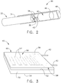
FIG. 2 is perspective view of a resistance temperature detector assembly. -
FIG. 3 is an isometric view of a first example of a resistance temperature detector element. -
FIG. 4 is an isometric view of a second example of a resistance temperature detector element. -
FIG. 5 is an isometric view of a third example of a resistance temperature detector element. -
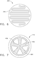
FIG. 6 is a top view of a fourth example of a resistance temperature detector element. -
FIG. 7 is a top view of a fifth example of a resistance temperature detector element. -
FIG. 8 is a top view of a sixth example of a resistance temperature detector element. -
FIG. 9 is a top view of a seventh example of a resistance temperature detector element. -
FIG. 10 is a first embodiment of a resistance temperature detector element with an alternative design. -
FIG. 11 is an alternative embodiment of the resistance temperature detector element ofFIG. 10 . -
Figures 3 - 9 show examples that do not fall within the scope of the claims. - Reference now will be made in detail to embodiments provided, one or more examples of which are illustrated in the drawings. Each example is provided by way of explanation, not limitation of the disclosed embodiments. In fact, it will be apparent to those skilled in the art that various modifications and variations can be made in the present embodiments without departing from the scope of the disclosure. For instance, features illustrated or described as part of one embodiment can be used with another embodiment to still yield further embodiments. Thus it is intended that the present invention covers such modifications and variations as come within the scope of the appended claims and their equivalents.
- Present embodiments provide structure for detecting high temperatures of gas flow within a gas turbine engine. The high temperature (RTD) utilizes an insulating material and a resistive material disposed on or about the resistive material. Leads extend from the insulating material and detector element is positioned within a housing.
- The terms fore and aft are used with respect to the engine axis and generally mean toward the front of the turbine engine or the rear of the turbine engine in the direction of the engine axis, respectively. As used herein, the term "software" and "firmware" are interchangeable including any computer programs stored in memory for execution by processor, including RAM memory, ROM memory, EPROM memory, EEPROM memory and non-volatile RAM (NVRAM) memory. The memory types are exemplary only and thus are not limiting as to the types of memory useful for storage in the computer program. As will be appreciated on the foregoing specification, the above described embodiments of the disclosure may be implemented using computer programming or engineering techniques including computer software, phoneware, hardware, or any combination of subset thereof, wherein the technical effect is for sensing a process parameter using a process sensor where slow response time may introduce errors into the value of the sensing parameter in input to the processor or control logic for the avionics system. Any such resulting program, having computer-readable code means, may be embodied or provided within one or more computer-readable media, thereby making a computer program product, i.e., an article of manufacture, according to the discussed embodiments of the disclosure. The computer-readable media may be, for example, but is not limited to, a fixed "hard" drive diskette, optical disk, magnetic tape, semi-conductor memory such as read-only memory (ROM) and that and/or any transmitting/receiving media such as the Internet or other communication network. The article of manufacture contains a computer code. The computer code may be made and/or used by executing the code directly from one medium, by copying the code from one medium to another medium or by transmitting the code of the network.
- Referring now to
FIGS. 1-11 , various examples and embodiments of a high temperature resistance temperature detector are shown. The resistance temperature detector is capable of operating in higher temperatures enabling closer positioning of the RTD toward the combustor exit. This will improve reactance of, and reduce errors, in computer control logic which may occur due to rapid changes in temperature or other characteristics. Engine control logic may be represented in various forms. For purpose of this disclosure, the control logic may be operated by a processor which operates software or firmware, for example. The term processor, is used herein, refers to central processing units, microprocessors, microcontrollers, reduced instruction set circuits (RISC), application specific integrated circuits (ASIC), logic circuits, and any other circuit or processor capable of executing the functions described herein. - Referring initially to
FIG. 1 , a schematic side section view of agas turbine engine 10 is shown having anengine inlet end 12, acompressor 14, acombustor 16 and a multi-stagehigh pressure turbine 20. Thegas turbine 10 may be used for aviation, power generation, industrial, marine or the like. Depending on the usage, theengine inlet end 12 may alternatively contain multi-stage compressors rather than a fan. Thegas turbine 10 is axi-symmetrical aboutengine axis 26 orshaft 24 so that various engine components rotate thereabout. In operation air enters through theair inlet end 12 of theengine 10 and moves through at least one stage of compression where the air pressure is increased and directed to thecombustor 16. The compressed air is mixed with fuel and burned providing the hot combustion gas which exits thecombustor 16 toward thehigh pressure turbine 20. At thehigh pressure turbine 20, energy is extracted from the hot combustion gas causing rotation of turbine blades which in turn cause rotation of theshaft 24. Theshaft 24 passes toward the front of the engine to continue rotation of the one or more compressor stages 14, aturbofan 18 or inlet fan blades, depending on the turbine design. The axis-symmetrical shaft 24 extends through theturbine engine 10, from the forward end to an aft end. Theshaft 24 is supported by bearings along its length. Theshaft 24 may be hollow to allow rotation of a lowpressure turbine shaft 28 therein. Bothshafts centerline 26 of the engine. During operation theshafts turbine 20 andcompressor 14 in order to create power or thrust depending on the area of use, for example power, industrial or aviation. - Referring still to
FIG. 1 , theinlet 12 includes aturbofan 18 which has a plurality of blades. Theturbofan 18 is connected byshaft 28 to thelow pressure turbine 19 and creates thrust for theturbine engine 10. Aft of thecombustor 16 is one exemplary location for atemperature detector 30. Although an exhaust gas temperature is discussed herein, sensors of the instant disclosure may be utilized at various locations such as thecompressor 14turbines - Referring now to
FIG. 2 , aresistance temperature detector 30 is depicted in perspective view. The detector has a high temperature operational capability with a generally linear and stable resistance versus temperature characteristic. The assembly includes acable 32. The outer portion of thecable 32 may have asheath 34 formed of for example, HA 230 or Platinum or Platinum alloy, forexample Platinum 10% Rhodium orPlatinum 20% Rhodium, and which surrounds aninsulation 36. Theinsulation 36 may be formed of crushed or powder form magnesium oxide or aluminum oxide, for example although other materials may be utilized. Additionally, thesheath 34 may be oxide dispersion strengthened or grain-stabilized alloys to reduce grain growth at elevated temperatures. Thesheath 34 has the additional function of limiting electromagnetic interference noise. - Extending through the
cable 32 arewires 38, which are exposed at an end of thecable 32. Thewires 38 extend from theinsulation 36 and provide an interconnect for a junction withleads 42 which connect to a resistancetemperature detector element 40. Thecable 32 may havemultiple wires 38 within theinsulation 36. In the depicted example, thecable 32 includes four wires, wherein pairs of thewires 38 are joined to form two U-shaped conductors. The number of wires provided within thecable 32 will be dependent upon the circuit being formed and may vary. Thewires 38 may be formed of grain stabilized platinum or zirconia grain stabilized platinum, for example in order to limit joining of grain at elevated temperature. It is desirable that thedetector element 40 fail prior to failure of thecable 32 to preclude foreign object damage within the engine core. Extending from thewires 38 and in conductive communication therewith are first and second leads 42. The leads 42 provide a circuit connection with thewires 38 and extend an opposite end to the remaining portion of the resistancetemperature detector element 40. According to one exemplary embodiment two leads 42 are utilized in the depicted construction. However this is merely exemplary as alternate constructions may be utilized. The leads 42 may be formed of grain stabilized or zirconia grain stabilized platinum. Similarly, thewire 38 is a grain stabilized wire or zirconia grain stabilized platinum as well. Grain growth within the structure is the process by which these grains effectively combine and hence grow in size during exposure to elevated temperatures. - This may result in various problems and therefore grain stabilized wire would be desirable. Similar material is utilized in the
wire 38 in theleads 42 in order to limit problems with dissimilar metals and differential thermal expansion and contraction. However, these materials are exemplary and one skilled in the art should recognize that alternate embodiments are within the scope of the present disclosure. According to one embodiment, theleads 42 may have a diameter of 0.254 mm (0.010 inch) but may be within the range of between about 0.0762 mm (0.003 inch) and about 0.762 mm (0.03 inch) and more preferably about 0.01778 mm (0.0007 inch) to about 0.381 mm (0.015 inch). As shown inFIG. 3 , the construction utilizes two 3-wire connections extending toward anRTD element 40 forming a 4-wire measurement circuit. The use of 4-wire measurement circuit aids in the elimination of temperature error measurement associated with the series resistance presented by thelead wires 38. - The resistance
temperature detector element 40 may take various forms to be discussed further herein. Theelement 40 may have an insulated portion, substrate orcarrier 50 and aresistive element 56 utilize therein and wherein the resistive element is in electric communication with theleads 42. A housing orseal element 46 may be positioned over theelement 40 and additionally covering the connection between theleads 42 and thewires 38. Thehousing 46 may be formed of HA 230, platinum or Platinum alloys such asPlatinum 20% Rhodium and may be a single piece construction or may be formed atube 46 with anend cap 48 which are joined together. Thehousing 46 may be metallic, a glazed ceramic or may be glass-based and may be welded or otherwise joined to thecable 32. One exemplary embodiment utilizes a hermetic compression glass seal at the transition of the lead wire from thehard lead wires 38. The coefficients of thermal expansion of all materials must be closely matched for device longevity at elevated temperatures. Tungsten sealing glasses may be used to encase the elements. The interior of thehousing 46 may include a powder filled alumina or hafnium for purpose of insulation according to some embodiments. According to other embodiments, the interior may be a hermetic environment, may be evacuated and/or or may be filled with an inert gas, such as for example high purity Argon or Nitrogen. Other gasses may be utilized. According to some embodiments, thehousing 46 may be powder filled and evacuated then backfilled with an inert non-oxygen atmosphere and hermetically sealed all of which surround the element in a mechanically supported non-oxidizing atmosphere. - For normal operation, it would be desirable for the
RTD 30 to operate properly within the following ranges. The operating temperature range of about 1088.706 to 1922.039 kelvin (1500 to about 3000 degrees Fahrenheit) and more particularly about 1283.15 to 1478.15 kelvin (1850 to about 2201 degrees Fahrenheit). The element resistance should be about 12 ohms at 32 degrees Fahrenheit with a resistance dynamic range of 5 Ohms to about 40 Ohms. Thesensor 30 should be accurate to greater of +/- 0.4% of point or about +/- 4.444 kelvin (8 degrees Fahrenheit). The excitation current (nominal) may be desirably be about 100 ma and (fault) at about 300 ma. This represents one embodiment of element parameter but should not be considered limiting as other parameters may be utilized. - Referring now to
FIG. 3 , a first example of resistivetemperature detector element 40 is shown. The structure includes an insulatingsubstrate 50 having afirst surface 52 in asecond surface 54. One of the surfaces includes aresistive element 56. Theresistive element 56 may be formed of various materials which are temperature resistant and may be oxide disposerd or grain stabilized. For example, one material may be a tungsten and rhenium wherein the tungsten is between about 70 - 98% and the rhenium is between about 2 - 30%, for example Tungsten 25% Rhenium alloy. The resistive elements of all of the embodiments may utilize materials in this range as this composition of tungsten and rhenium have been found to be able to withstand the temperatures in the range associated with high temperature combustion of agas turbine engine 10. As compared to various alloys such as Rhenium,molybdenum 50% Rhenium, Molybdenum, tungsten or tantalum, tungsten 25% Rhenium appears to have the most linear temperature to resistance profile between 255.372 and about 1922.039 kelvin (0 and about 3000 degrees Fahrenheit). - According to the first example, the
resistive element 56 includes a network of series andparallel circuit paths 57 which define a "thin-film" resistive device. Once formed, theresistive element 56 may be tuned to a desired resistivity by trimming or cutting thepaths 57 to a circuit which provides the desired resistance. The thin-film circuit further comprisescircuit pads 58 on the insulatingsubstrate 50 and which are in conductive communication withlead wire 42. Extending from thepads 58 by, for example, weld or brazed connection are theleads 42 which extend to thewires 38 of the cable 32 (FIG. 2 ) for conductive communication. Disposed above thesurface 52 having theresistive element 56 is a sealing and insulatinglayer 60. This sealing and insulatinglayer 60 may be one of glass or ceramic, for example. However, other materials may be utilized. Tungsten materials should not be exposed to elevated temperatures while in contact with oxygen or else oxidation will occur resulting in failure of the tungsten material. - One skilled in the art should also recognize that although the insulating
substrate 50 is shown to be formed in a rectangle shape, other geometric shapes such circular, oval, or polygonal shapes may be utilized rather than the rectangular shape of the exemplary depiction. Additionally, one skilled in the art should realize that while a single layer is shown for theRTD element 40, it is within the scope of this disclosure thatmultiple substrates 50 and resistive elements may be insulated from one another so as to allow stacking or laminating multiple of these circuits. - Referring now too
Fig. 4 , a second example of a resistancetemperature detector element 140 is shown. As opposed to the example ofFIG. 3 which was a thin film device, the embodiment ofFIG. 4 is a thick film device. The embodiment includes an insulatingsubstrate 150 upon which aresistive element 156 is deposited. This may be done, for example by laser vapor deposition or sintering. Theresistive element 156 may be formed of the tungsten-rhenium combination previously discussed. Theresistive element 156 is different from the network of paths previously described in that theelement 156 is generally a thick film of a preselected area of resistive material. Like thepaths 57 of theresistive element 56, thefilm 156 may be ablaited, laser trimmed or cut in order to tune or calibrate the resistivity to a desired amount. The embodiment also comprisescircuit pads 158 for lead wire attachment. The leads 42 are then connected to thepads 158 in order to form a circuit between theleads 42, thepads 158 and theresistive element 156. Lead wires may be welded or brazed to thecircuit pads 158. - Similarly to the previous example, the
element 140 may also have a top seal or insulation layer 160. - Referring now to
FIG. 5 , a third example of a resistancetemperature detector element 240 is depicted. Theelement 240 includes insulatingsubstrate 250. In the exemplary embodiment, thesubstrate 250 is a circular or disk shaped wafer as opposed to the rectangular shape previously shown and described. Again alternate shapes may be utilized. Aresistive element 256 is depicted on one of the surfaces of the insulatinglayer 250. Theresistance circuit 256 is formed in a spiral shape according to the exemplary embodiment. Theresistive element 256 has a first end and a second end which are in electric communication withleads 42 extending from an opposite surface of the insulatinglayer 250. In the exemplary embodiment onelead 42 extends to near a bottom center of the insulatinglayer 250 while asecond lead 42 extends to near an edge of the insulating layer for electric communication with the ends of thecircuits 256. - Referring now to
FIG. 6-9 , alternate patterns for the resistive element are depicted for use with the insulating layers. With reference first toFIG 6 , theRTD element 340 is shown with acurvilinear resistance element 356. The ends of theresistive element 356 may be disposed at various locations on the disk 350 for electric connection with the leads 42 (not shown). - Referring to
FIG. 7 , a top view is shown. Theresistive element 440 is circular and generally includes a plurality ofspokes 456 which are like a thick film design. The center of theresistive element 440 includes a center electrode and a second electrode is disposed along the edge. - Referring to
FIG. 8 , a furtheralternative RTD element 540 is depicted. Again this embodiment is shown in the context of use with a disk shaped insulatinglayer 550 however alternate shapes may be utilized. Theresistive element 556 includes a network of serial andparallel paths 557. - Referring to
FIG. 9 , also is a top view of aresistive temperature detector 640 having a thick film circuit. According to this embodiment, theresistive element 656 utilizes a deposited ring shaped on the insulated carrier 650. Electrodes are located along edges of the circuit to electrically communicate with the current source. The ring or washer shape may be ablaited, blasted or cut to form a desirable resistivity as previously described. - Like the example discussed with
FIG. 3 , the examples shown inFIGS. 4-9 may be stacked in a laminate or sandwiched construction. - Referring to
FIG. 10 an embodiment of a resistivetemperature detector element 740 is depicted in side view. And insulatingmaterial 750 is shown in the form of cylindrical mandrel. Thematerial 750 has afirst end 752 and a seconddistal end 754. At thefirst end 752,lead wires 42 extend into the insulatingmaterial 750 through bore or through-holes depicted in broken line. Aresistive element 756 is wrapped around themandrel 750 between thefirst end 752 seconds end 754. Theresistive element 756 has a first end which is welded or brazed to one of theleads 42 and a second end which is welded or brazed to thesecond lead 42. Theresistive element 756 may be in the form of a fine element wire, a thin film or a thick film structure as previously described. A glass or ceramic outer insulating coating orhousing 760 may be disposed around thematerial 750 to seal the structure therein. The interior of the coating orhousing 760 may include an inert gas or may be some other hermetically sealed non-oxidizing environment. Further, strain relief potted material may be located at ends of themandrel 750 or along the path of the resistive elements and 756. Again, as one skilled in the art will understand, tungsten material may not be in contact with an oxidizing atmosphere at elevated temperatures. It is desirable that conformal hermetic coatings or hermetic non-oxidizing atmospheric vessel may be utilized. - Referring now to
FIG. 11 , a further alternative embodiment to that shown inFIG. 10 is depicted in side view. Theresistive element 840 includes amandrel 850 which includes an outer surface which is serrated or curvilinear sidewall defined byplurality peaks 851 andvalleys 853. Thevalleys 853 provide a position where in theresistive element 856 may be seated and come to a neutral position. Thus thevalleys 853 function as a wire retaining feature. The leads 42 enter the insulatingmandrel 850 near afirst end 852 and connect with ends of theresistive element 856 to form a circuit. Ahousing 860 covers the structure to provide an anti-oxidizing environment through any of the various methods previously provided. Thehousing 860 may be sealed against the insulatingmaterial 850 or against the cable sheath 34 (FIG. 2 ). - While multiple inventive embodiments have been described and illustrated herein, those of ordinary skill in the art will readily envision a variety of other means and/or structures for performing the function and/or obtaining the results and/or one or more of the advantages described herein, and each of such variations and/or modifications is deemed to be within the scope of the invent of embodiments described herein. More generally, those skilled in the art will readily appreciate that all parameters, dimensions, materials, and configurations described herein are meant to be exemplary and that the actual parameters, dimensions, materials, and/or configurations will depend upon the specific application or applications for which the inventive teachings is/are used. Those skilled in the art will recognize, or be able to ascertain using no more than routine experimentation, many equivalents to the specific inventive embodiments described herein. It is, therefore, to be understood that the foregoing embodiments are presented by way of example only and that, within the scope of the appended claims and equivalents thereto, inventive embodiments may be practiced otherwise than as specifically described and claimed. Inventive embodiments of the present disclosure are directed to each individual feature, system, article, material, kit, and/or method described herein. In addition, any combination of two or more such features, systems, articles, materials, kits, and/or methods, if such features, systems, articles, materials, kits, and/or methods are not mutually inconsistent, is included within the inventive scope of the present disclosure.
- Examples are used to disclose the embodiments, including the best mode, and also to enable any person skilled in the art to practice the apparatus and/or method, including making and using any devices or systems and performing any incorporated methods.
- These examples are not intended to be exhaustive or to limit the disclosure to the precise steps and/or forms disclosed, and many modifications and variations are possible in light of the above teaching. Features described herein may be combined in any combination. Steps of a method described herein may be performed in any sequence that is physically possible.
- All definitions, as defined and used herein, should be understood to control over dictionary definitions, definitions in documents incorporated by reference, and/or ordinary meanings of the defined terms. The indefinite articles "a" and "an," as used herein in the specification and in the claims, unless clearly indicated to the contrary, should be understood to mean "at least one." The phrase "and/or," as used herein in the specification and in the claims, should be understood to mean "either or both" of the elements so conjoined, i.e., elements that are conjunctively present in some cases and disjunctively present in other cases. Furthermore, references to one embodiment are not intended to be interpreted as excluding the existence of additional embodiments that may also incorporate the recited feature.
- It should also be understood that, unless clearly indicated to the contrary, in any methods claimed herein that include more than one step or act, the order of the steps or acts of the method is not necessarily limited to the order in which the steps or acts of the method are recited.
- In the claims, as well as in the specification above, all transitional phrases such as "comprising," "including," "carrying," "having," "containing," "involving," "holding," "composed of," and the like are to be understood to be open-ended, i.e., to mean including but not limited to.
Claims (11)
- A resistive temperature detector (40,70), comprising:an insulating carrier being a generally cylindrical mandrel (750);characterized by:a resistive element (56,756) being one of sintered, deposited on or wrapped about said insulating carrier (50,750), said resistive element being a tungsten-rhenium material;said insulating carrier (50,750) and said resistive element (56,756) are formed of materials capable of withstanding a high temperature gas flow having a temperature range between about 1088.706 kelvin and 1922.039 kelvin (1500 degrees and 3000 degrees Fahrenheit);leads (42) extending from said insulating carrier and in electrical communication with said resistive element, said leads and at least one interconnect wire being formed of grain stabilized platinum; anda housing (46,760) disposed over said insulating carrier and said resistive element providing an oxygen-free environment.
- The resistive temperature detector (40,740) of Claim 1, wherein said insulating carrier (50,750) is a ceramic.
- The resistive temperature detector (40,740) of Claim 1 or 2, wherein said mandrel has through holes receiving said leads (42).
- The resistive temperature detector (740) of Claim 3, wherein said resistive element (756) is a wire wrapped about said mandrel (750).
- The resistive temperature detector (740) of Claim 3, wherein said resistive element (756) is deposited on said mandrel (750).
- The resistive temperature detector (40,740) of any preceding Claim, wherein said leads (42) are a zirconia grain stabilized platinum.
- The resistive temperature detector (40,740) of any preceding Claim, wherein said housing (46) is a hermetic housing packed with an insulating powder.
- A resistive temperature detector (40,740) according to claim 1, further comprising:a seal element (60,760) covering said insulating carrier and said resistive element;grain stabilized platinum leads extending from said insulating carrier and in communication with said resistive element;said grain stabilized platinum leads further in electrical communication with grain stabilized platinum interconnect wires.
- The resistive temperature detector (40,740) of Claim 8, said seal element (60,760) being glass, wherein preferably an interior of said glass being a hermetic environment.
- The resistance temperature detector (840) of Claim 1, wherein the resistive element is wrapped around the mandrel, said mandrel (850) having an outer surface with a plurality of peaks (851) and valleys (853).
- The resistance temperature detector of Claim 10, said resistive element (856) disposed within said valleys (853) so as to retain said resistive element in position.
Applications Claiming Priority (1)
| Application Number | Priority Date | Filing Date | Title |
|---|---|---|---|
| US13/590,125 US9103731B2 (en) | 2012-08-20 | 2012-08-20 | High temperature resistive temperature detector for exhaust gas temperature measurement |
Publications (3)
| Publication Number | Publication Date |
|---|---|
| EP2700924A2 EP2700924A2 (en) | 2014-02-26 |
| EP2700924A3 EP2700924A3 (en) | 2015-09-09 |
| EP2700924B1 true EP2700924B1 (en) | 2017-10-11 |
Family
ID=48985638
Family Applications (1)
| Application Number | Title | Priority Date | Filing Date |
|---|---|---|---|
| EP13180543.4A Not-in-force EP2700924B1 (en) | 2012-08-20 | 2013-08-15 | High temperature resistive temperature detector for exhaust gas temperature measurement |
Country Status (4)
| Country | Link |
|---|---|
| US (1) | US9103731B2 (en) |
| EP (1) | EP2700924B1 (en) |
| JP (1) | JP6461459B2 (en) |
| CA (1) | CA2823368A1 (en) |
Families Citing this family (10)
| Publication number | Priority date | Publication date | Assignee | Title |
|---|---|---|---|---|
| EP2921833B1 (en) * | 2014-03-18 | 2016-12-28 | Mettler-Toledo GmbH | Thermoanalytical sensor and method for its production |
| CN104535216B (en) * | 2014-12-02 | 2017-05-03 | 苏州长风航空电子有限公司 | Multi-redundant metal framework platinum resistor temperature sensing element and manufacturing method thereof |
| US10247619B2 (en) * | 2015-05-01 | 2019-04-02 | Vishay Measurements Group, Inc. | Resistance temperature detector with medium temperature coefficient and high linearity |
| US10151643B2 (en) * | 2016-08-22 | 2018-12-11 | The Boeing Company | Thermal event indicator for aircraft engine |
| US11371892B2 (en) * | 2019-06-28 | 2022-06-28 | Fluke Corporation | Platinum resistance temperature sensor having floating platinum member |
| US11709103B2 (en) * | 2020-05-20 | 2023-07-25 | Pratt & Whitney Canada Corp. | Temperature sensor and method of manufacture |
| KR102490817B1 (en) * | 2020-12-11 | 2023-01-19 | 연세대학교 원주산학협력단 | Resistance temperature detector having circular pattern |
| US12092025B2 (en) * | 2021-12-22 | 2024-09-17 | Unison Industries, Llc | Turbine engine exhaust gas temperature sensor |
| US20230393051A1 (en) * | 2022-04-29 | 2023-12-07 | The United States Of America, As Represented By The Secretary Of The Navy | Apparatus and methods for automated corrosion testing |
| US20240280419A1 (en) * | 2023-02-20 | 2024-08-22 | Unison Industries, Llc | Turbine engine exhaust gas temperature sensor |
Citations (1)
| Publication number | Priority date | Publication date | Assignee | Title |
|---|---|---|---|---|
| US2780703A (en) * | 1952-11-12 | 1957-02-05 | Gen Electric | Quick response resistance temperature detector |
Family Cites Families (68)
| Publication number | Priority date | Publication date | Assignee | Title |
|---|---|---|---|---|
| US2636819A (en) * | 1951-01-31 | 1953-04-28 | Baker & Co Inc | Grain stabilizing metals and alloys |
| US3509320A (en) | 1967-07-19 | 1970-04-28 | Rosemount Eng Co Ltd | Roll heater and temperature sensor assembly |
| AT278184B (en) | 1967-08-28 | 1970-01-26 | Plansee Metallwerk | Rotating anode for X-ray tubes |
| GB1291827A (en) | 1968-10-28 | 1972-10-04 | Rosemount Eng Co Ltd | Improvements in or relating to temperature measuring apparatus |
| US3607447A (en) | 1970-04-16 | 1971-09-21 | Bayard C Davis | Nonwelded thermocouple junctions |
| US3725837A (en) | 1971-09-13 | 1973-04-03 | Rosemount Eng Co Ltd | Platinum resistance temperature sensors |
| US3761857A (en) * | 1971-10-04 | 1973-09-25 | Rosemount Inc | Resistance wire temperature sensor and method of making same |
| US3833410A (en) | 1971-12-30 | 1974-09-03 | Trw Inc | High stability thin film alloy resistors |
| DE2411995A1 (en) | 1973-04-20 | 1974-10-31 | Plansee Metallwerk | DEVICE FOR TEMPERATURE MEASUREMENT USING THERMOCOUPLES |
| US3798760A (en) | 1973-05-11 | 1974-03-26 | Rosemount Inc | Method of making resistance wire temperature sensor |
| GB1454816A (en) | 1974-02-19 | 1976-11-03 | Rosemount Eng Co Ltd | Resistance thermometer sensors |
| US4321827A (en) | 1980-03-31 | 1982-03-30 | Rosemount Inc. | Self aligning surface temperature sensor |
| US4406154A (en) * | 1982-02-22 | 1983-09-27 | General Electric Company | Low level alkali metal detection in combustion gas streams |
| US4808009A (en) | 1986-06-05 | 1989-02-28 | Rosemount, Inc. | Integrated semiconductor resistance temperature sensor and resistive heater |
| CH672860A5 (en) | 1986-09-29 | 1989-12-29 | Balzers Hochvakuum | |
| US4929092A (en) * | 1987-06-12 | 1990-05-29 | Mitsubishi Jukogyo Kabushiki Kaisha | Resistance temperature detector |
| JP2605297B2 (en) * | 1987-09-04 | 1997-04-30 | 株式会社村田製作所 | Platinum temperature sensor and method of manufacturing the same |
| US4916715A (en) | 1988-04-13 | 1990-04-10 | General Electric Company | Method and apparatus for measuring the distribution of heat flux and heat transfer coefficients on the surface of a cooled component used in a high temperature environment |
| US4836012A (en) | 1988-05-26 | 1989-06-06 | Ametek, Inc. | Gas sensor |
| JP3051276B2 (en) | 1993-01-22 | 2000-06-12 | 双葉電子工業株式会社 | Fluorescent display tube and Re-W material for fluorescent display tube |
| US5369993A (en) | 1993-06-30 | 1994-12-06 | The B. F. Goodrich Company | Three axis air data system for air vehicles |
| US5731507A (en) | 1993-09-17 | 1998-03-24 | Rosemount Aerospace, Inc. | Integral airfoil total temperature sensor |
| JP3175890B2 (en) * | 1993-12-27 | 2001-06-11 | 日本碍子株式会社 | Temperature sensor |
| US5520461A (en) | 1994-03-02 | 1996-05-28 | Alliedsignal Inc. | Airtight thermocouple probe |
| IN187185B (en) | 1995-04-25 | 2002-02-23 | Siemens Ag | |
| US5653538A (en) | 1995-06-07 | 1997-08-05 | Rosemount Aerospace Inc. | Total temperature probe |
| US5772325A (en) | 1995-11-20 | 1998-06-30 | Motorola, Inc. | Apparatus for providing surface images and method for making the apparatus |
| US6081182A (en) * | 1996-11-22 | 2000-06-27 | Matsushita Electric Industrial Co., Ltd. | Temperature sensor element and temperature sensor including the same |
| US5864282A (en) | 1996-11-29 | 1999-01-26 | Marchi Associates, Inc. | Unique strain relief junction |
| US5999081A (en) | 1996-11-29 | 1999-12-07 | Marchi Associates, Inc. | Shielding unique for filtering RFI and EFI interference signals from the measuring elements |
| KR100228046B1 (en) * | 1997-03-19 | 1999-11-01 | 정명세 | High temperature platinum resistance thermometer |
| US5896081A (en) | 1997-06-10 | 1999-04-20 | Cyntec Company | Resistance temperature detector (RTD) formed with a surface-mount-device (SMD) structure |
| JP3306427B2 (en) | 1997-11-21 | 2002-07-24 | いすゞ自動車株式会社 | Sheath structure |
| KR19990066851A (en) | 1998-01-12 | 1999-08-16 | 카와무라 히데오 | Thermocouples for Metal Melt Temperature Measurement |
| US6744346B1 (en) | 1998-02-27 | 2004-06-01 | Micron Technology, Inc. | Electronic device workpieces, methods of semiconductor processing and methods of sensing temperature of an electronic device workpiece |
| EP1306454B1 (en) | 2001-10-24 | 2004-10-06 | Siemens Aktiengesellschaft | Rhenium containing protective coating protecting a product against corrosion and oxidation at high temperatures |
| US6162552A (en) | 1998-12-03 | 2000-12-19 | General Electric Company | Rhenium-coated tungsten-based alloy and composite articles and method therefor |
| DE19901184C1 (en) | 1999-01-14 | 2000-10-26 | Sensotherm Temperatursensorik | Platinum temperature sensor and method of manufacturing the same |
| US6354736B1 (en) | 1999-03-24 | 2002-03-12 | Honeywell International Inc. | Wide temperature range RTD |
| JP4437592B2 (en) | 2000-04-24 | 2010-03-24 | いすゞ自動車株式会社 | Fast response thermocouple |
| FR2808874B1 (en) | 2000-05-15 | 2002-07-26 | Auxitrol Sa | SENSOR FOR MEASUREMENT OF PHYSICAL PARAMETERS ON A FLUID FLOW AND IN PARTICULAR AIR TEMPERATURE SENSOR |
| US6624577B2 (en) | 2001-03-19 | 2003-09-23 | General Electric Company | Tungsten-rhenium filament and method for producing same |
| WO2003008928A2 (en) * | 2001-07-16 | 2003-01-30 | Sensor Tech, Inc. | Sensor device and method for qualitative and quantitative analysis of gas phase substances |
| US6609825B2 (en) | 2001-09-21 | 2003-08-26 | Rosemount Aerospace Inc. | Total air temperature probe providing improved anti-icing performance and reduced deicing heater error |
| US6607302B2 (en) | 2001-09-24 | 2003-08-19 | Visteon Global Technologies, Inc. | Temperature sensor housing design |
| US20040244879A1 (en) * | 2001-10-09 | 2004-12-09 | Takashi Tanaka | Tunsten wire, cathode heater, and filament for vibration service lamp |
| US6924046B2 (en) | 2001-10-24 | 2005-08-02 | Siemens Aktiengesellschaft | Rhenium-containing protective layer for protecting a component against corrosion and oxidation at high temperatures |
| KR100805843B1 (en) | 2001-12-28 | 2008-02-21 | 에이에스엠지니텍코리아 주식회사 | Copper wiring forming method, semiconductor device and copper wiring forming system manufactured accordingly |
| US6597107B1 (en) | 2002-01-11 | 2003-07-22 | General Electric Company | Tungsten-rhenium filament and method for producing same |
| US7106167B2 (en) * | 2002-06-28 | 2006-09-12 | Heetronix | Stable high temperature sensor system with tungsten on AlN |
| GB0225670D0 (en) | 2002-11-05 | 2002-12-11 | Rolls Royce Plc | Method of forming a diffusion barrier on a titanium alloy substrate |
| KR20040049077A (en) | 2002-12-03 | 2004-06-11 | 현대자동차주식회사 | Apparatus for measuring piston temperature |
| JP2004317499A (en) | 2003-03-28 | 2004-11-11 | Ngk Spark Plug Co Ltd | Temperature sensor |
| US6881932B2 (en) | 2003-04-29 | 2005-04-19 | Harco Laboratories, Inc. | High reliability heater modules |
| US20050115329A1 (en) * | 2003-10-23 | 2005-06-02 | Gregory Otto J. | High temperature strain gages |
| US7061364B2 (en) | 2003-11-13 | 2006-06-13 | Harco Labratories, Inc. | Thermal variable resistance device with protective sheath |
| US7026908B2 (en) | 2003-11-13 | 2006-04-11 | Harco Laboratories, Inc. | Extended temperature range thermal variable-resistance device |
| US7915994B2 (en) | 2003-11-13 | 2011-03-29 | Harco Laboratories, Inc. | Thermal variable resistance device with protective sheath |
| US7026909B2 (en) | 2003-12-12 | 2006-04-11 | Rosemount Aerospace, Inc. | Housing for temperature sensing assemblies in a thermometer |
| US20050129565A1 (en) | 2003-12-15 | 2005-06-16 | Ohriner Evan K. | Tungsten alloy high temperature tool materials |
| US7611280B2 (en) | 2003-12-16 | 2009-11-03 | Harco Laboratories, Inc. | EMF sensor with protective sheath |
| US7004626B1 (en) | 2004-03-05 | 2006-02-28 | Turbo Research, Inc. | Fast acting thermocouple |
| US7031871B2 (en) | 2004-06-04 | 2006-04-18 | Rosemount Aerospace, Inc. | Sensor assembly for determining total temperature, static temperature and Mach number |
| US20060219330A1 (en) | 2005-03-29 | 2006-10-05 | Honeywell International, Inc. | Nickel-based superalloy and methods for repairing gas turbine components |
| JP4832044B2 (en) * | 2005-09-28 | 2011-12-07 | 株式会社山武 | Temperature detector |
| JP2007187562A (en) * | 2006-01-13 | 2007-07-26 | Ngk Spark Plug Co Ltd | Temperature sensor element and temperature sensor |
| US8198976B2 (en) * | 2006-08-18 | 2012-06-12 | The United States Of America As Represented By The Administrator Of The National Aeronautics And Space Administration | Flexible thin metal film thermal sensing system |
| JP2009085944A (en) * | 2007-09-11 | 2009-04-23 | Yamaha Motor Co Ltd | Gas sensor, air-fuel ratio control device, and transportation equipment |
-
2012
- 2012-08-20 US US13/590,125 patent/US9103731B2/en not_active Expired - Fee Related
-
2013
- 2013-08-08 CA CA2823368A patent/CA2823368A1/en not_active Abandoned
- 2013-08-14 JP JP2013168412A patent/JP6461459B2/en not_active Expired - Fee Related
- 2013-08-15 EP EP13180543.4A patent/EP2700924B1/en not_active Not-in-force
Patent Citations (1)
| Publication number | Priority date | Publication date | Assignee | Title |
|---|---|---|---|---|
| US2780703A (en) * | 1952-11-12 | 1957-02-05 | Gen Electric | Quick response resistance temperature detector |
Also Published As
| Publication number | Publication date |
|---|---|
| CA2823368A1 (en) | 2014-02-20 |
| EP2700924A3 (en) | 2015-09-09 |
| US20140247106A1 (en) | 2014-09-04 |
| JP2014038099A (en) | 2014-02-27 |
| US9103731B2 (en) | 2015-08-11 |
| EP2700924A2 (en) | 2014-02-26 |
| JP6461459B2 (en) | 2019-01-30 |
Similar Documents
| Publication | Publication Date | Title |
|---|---|---|
| US9103731B2 (en) | High temperature resistive temperature detector for exhaust gas temperature measurement | |
| JP5561981B2 (en) | Blade tip clearance measurement sensor and clearance measurement method for gas turbine engine | |
| KR101467178B1 (en) | Turbine component instrumented to provide thermal measurements | |
| EP3159666B1 (en) | Thermocouple for gas turbine environments | |
| EP2610599B1 (en) | Temperature sensing device and method of assembling the same | |
| US10168228B2 (en) | Thermocouple apparatus and method | |
| JP2004197739A (en) | Temperature sensing structure, method of manufacturing the structure, gas turbine engine, and temperature control method | |
| EP2728303B1 (en) | Capacitive sensor device and method of manufacture | |
| US8736285B2 (en) | High temperature position sensor | |
| JP2013242317A (en) | Process sensor with convective increaser | |
| US20180258786A1 (en) | Sensor assembly for rotating devices and methods for fabricating | |
| US10126178B2 (en) | Fast response temperature sensor using a polyimide enclosed RTD | |
| EP2565607B1 (en) | A resistor and a method of manufacturing a resistor capable of operating at high temperatures | |
| EP1987334B1 (en) | Temprature sensor apparatus | |
| EP3667228A1 (en) | A probe for monitoring a moving engine element | |
| US20230156873A1 (en) | Electromagnetic-induction heating device for thin-film thermocouple on ceramic blade | |
| CA2487223C (en) | Extended temperature range thermal variable-resistance device | |
| JP2014153368A (en) | Embedded resistance temperature detector assembly | |
| US20240167887A1 (en) | Electrical connectivity to high temperature film sensor devices | |
| CN120101958A (en) | A thin film temperature sensor for in-situ measurement based on blades | |
| Nag | Thin-Film Thermocouple for High-Temperature Gas Turbine Applications | |
| JPH102808A (en) | Temperature sensor, method of manufacturing the same, and alarm device using the sensor |
Legal Events
| Date | Code | Title | Description |
|---|---|---|---|
| PUAI | Public reference made under article 153(3) epc to a published international application that has entered the european phase |
Free format text: ORIGINAL CODE: 0009012 |
|
| AK | Designated contracting states |
Kind code of ref document: A2 Designated state(s): AL AT BE BG CH CY CZ DE DK EE ES FI FR GB GR HR HU IE IS IT LI LT LU LV MC MK MT NL NO PL PT RO RS SE SI SK SM TR |
|
| AX | Request for extension of the european patent |
Extension state: BA ME |
|
| PUAL | Search report despatched |
Free format text: ORIGINAL CODE: 0009013 |
|
| AK | Designated contracting states |
Kind code of ref document: A3 Designated state(s): AL AT BE BG CH CY CZ DE DK EE ES FI FR GB GR HR HU IE IS IT LI LT LU LV MC MK MT NL NO PL PT RO RS SE SI SK SM TR |
|
| AX | Request for extension of the european patent |
Extension state: BA ME |
|
| RIC1 | Information provided on ipc code assigned before grant |
Ipc: G01K 13/02 20060101ALI20150731BHEP Ipc: G01K 1/12 20060101ALI20150731BHEP Ipc: G01K 7/18 20060101AFI20150731BHEP |
|
| 17P | Request for examination filed |
Effective date: 20160309 |
|
| RBV | Designated contracting states (corrected) |
Designated state(s): AL AT BE BG CH CY CZ DE DK EE ES FI FR GB GR HR HU IE IS IT LI LT LU LV MC MK MT NL NO PL PT RO RS SE SI SK SM TR |
|
| 17Q | First examination report despatched |
Effective date: 20160728 |
|
| GRAP | Despatch of communication of intention to grant a patent |
Free format text: ORIGINAL CODE: EPIDOSNIGR1 |
|
| INTG | Intention to grant announced |
Effective date: 20170502 |
|
| GRAS | Grant fee paid |
Free format text: ORIGINAL CODE: EPIDOSNIGR3 |
|
| GRAA | (expected) grant |
Free format text: ORIGINAL CODE: 0009210 |
|
| AK | Designated contracting states |
Kind code of ref document: B1 Designated state(s): AL AT BE BG CH CY CZ DE DK EE ES FI FR GB GR HR HU IE IS IT LI LT LU LV MC MK MT NL NO PL PT RO RS SE SI SK SM TR |
|
| REG | Reference to a national code |
Ref country code: GB Ref legal event code: FG4D |
|
| REG | Reference to a national code |
Ref country code: CH Ref legal event code: EP |
|
| REG | Reference to a national code |
Ref country code: IE Ref legal event code: FG4D |
|
| REG | Reference to a national code |
Ref country code: AT Ref legal event code: REF Ref document number: 936464 Country of ref document: AT Kind code of ref document: T Effective date: 20171115 |
|
| REG | Reference to a national code |
Ref country code: DE Ref legal event code: R096 Ref document number: 602013027743 Country of ref document: DE |
|
| REG | Reference to a national code |
Ref country code: NL Ref legal event code: MP Effective date: 20171011 |
|
| REG | Reference to a national code |
Ref country code: LT Ref legal event code: MG4D |
|
| REG | Reference to a national code |
Ref country code: AT Ref legal event code: MK05 Ref document number: 936464 Country of ref document: AT Kind code of ref document: T Effective date: 20171011 |
|
| PG25 | Lapsed in a contracting state [announced via postgrant information from national office to epo] |
Ref country code: NL Free format text: LAPSE BECAUSE OF FAILURE TO SUBMIT A TRANSLATION OF THE DESCRIPTION OR TO PAY THE FEE WITHIN THE PRESCRIBED TIME-LIMIT Effective date: 20171011 |
|
| PG25 | Lapsed in a contracting state [announced via postgrant information from national office to epo] |
Ref country code: ES Free format text: LAPSE BECAUSE OF FAILURE TO SUBMIT A TRANSLATION OF THE DESCRIPTION OR TO PAY THE FEE WITHIN THE PRESCRIBED TIME-LIMIT Effective date: 20171011 Ref country code: NO Free format text: LAPSE BECAUSE OF FAILURE TO SUBMIT A TRANSLATION OF THE DESCRIPTION OR TO PAY THE FEE WITHIN THE PRESCRIBED TIME-LIMIT Effective date: 20180111 Ref country code: FI Free format text: LAPSE BECAUSE OF FAILURE TO SUBMIT A TRANSLATION OF THE DESCRIPTION OR TO PAY THE FEE WITHIN THE PRESCRIBED TIME-LIMIT Effective date: 20171011 Ref country code: LT Free format text: LAPSE BECAUSE OF FAILURE TO SUBMIT A TRANSLATION OF THE DESCRIPTION OR TO PAY THE FEE WITHIN THE PRESCRIBED TIME-LIMIT Effective date: 20171011 Ref country code: SE Free format text: LAPSE BECAUSE OF FAILURE TO SUBMIT A TRANSLATION OF THE DESCRIPTION OR TO PAY THE FEE WITHIN THE PRESCRIBED TIME-LIMIT Effective date: 20171011 |
|
| PG25 | Lapsed in a contracting state [announced via postgrant information from national office to epo] |
Ref country code: GR Free format text: LAPSE BECAUSE OF FAILURE TO SUBMIT A TRANSLATION OF THE DESCRIPTION OR TO PAY THE FEE WITHIN THE PRESCRIBED TIME-LIMIT Effective date: 20180112 Ref country code: AT Free format text: LAPSE BECAUSE OF FAILURE TO SUBMIT A TRANSLATION OF THE DESCRIPTION OR TO PAY THE FEE WITHIN THE PRESCRIBED TIME-LIMIT Effective date: 20171011 Ref country code: IS Free format text: LAPSE BECAUSE OF FAILURE TO SUBMIT A TRANSLATION OF THE DESCRIPTION OR TO PAY THE FEE WITHIN THE PRESCRIBED TIME-LIMIT Effective date: 20180211 Ref country code: BG Free format text: LAPSE BECAUSE OF FAILURE TO SUBMIT A TRANSLATION OF THE DESCRIPTION OR TO PAY THE FEE WITHIN THE PRESCRIBED TIME-LIMIT Effective date: 20180111 Ref country code: HR Free format text: LAPSE BECAUSE OF FAILURE TO SUBMIT A TRANSLATION OF THE DESCRIPTION OR TO PAY THE FEE WITHIN THE PRESCRIBED TIME-LIMIT Effective date: 20171011 Ref country code: LV Free format text: LAPSE BECAUSE OF FAILURE TO SUBMIT A TRANSLATION OF THE DESCRIPTION OR TO PAY THE FEE WITHIN THE PRESCRIBED TIME-LIMIT Effective date: 20171011 Ref country code: RS Free format text: LAPSE BECAUSE OF FAILURE TO SUBMIT A TRANSLATION OF THE DESCRIPTION OR TO PAY THE FEE WITHIN THE PRESCRIBED TIME-LIMIT Effective date: 20171011 |
|
| REG | Reference to a national code |
Ref country code: DE Ref legal event code: R097 Ref document number: 602013027743 Country of ref document: DE |
|
| REG | Reference to a national code |
Ref country code: FR Ref legal event code: PLFP Year of fee payment: 6 |
|
| PG25 | Lapsed in a contracting state [announced via postgrant information from national office to epo] |
Ref country code: DK Free format text: LAPSE BECAUSE OF FAILURE TO SUBMIT A TRANSLATION OF THE DESCRIPTION OR TO PAY THE FEE WITHIN THE PRESCRIBED TIME-LIMIT Effective date: 20171011 Ref country code: CZ Free format text: LAPSE BECAUSE OF FAILURE TO SUBMIT A TRANSLATION OF THE DESCRIPTION OR TO PAY THE FEE WITHIN THE PRESCRIBED TIME-LIMIT Effective date: 20171011 Ref country code: EE Free format text: LAPSE BECAUSE OF FAILURE TO SUBMIT A TRANSLATION OF THE DESCRIPTION OR TO PAY THE FEE WITHIN THE PRESCRIBED TIME-LIMIT Effective date: 20171011 Ref country code: SK Free format text: LAPSE BECAUSE OF FAILURE TO SUBMIT A TRANSLATION OF THE DESCRIPTION OR TO PAY THE FEE WITHIN THE PRESCRIBED TIME-LIMIT Effective date: 20171011 |
|
| PLBE | No opposition filed within time limit |
Free format text: ORIGINAL CODE: 0009261 |
|
| STAA | Information on the status of an ep patent application or granted ep patent |
Free format text: STATUS: NO OPPOSITION FILED WITHIN TIME LIMIT |
|
| PG25 | Lapsed in a contracting state [announced via postgrant information from national office to epo] |
Ref country code: PL Free format text: LAPSE BECAUSE OF FAILURE TO SUBMIT A TRANSLATION OF THE DESCRIPTION OR TO PAY THE FEE WITHIN THE PRESCRIBED TIME-LIMIT Effective date: 20171011 Ref country code: SM Free format text: LAPSE BECAUSE OF FAILURE TO SUBMIT A TRANSLATION OF THE DESCRIPTION OR TO PAY THE FEE WITHIN THE PRESCRIBED TIME-LIMIT Effective date: 20171011 Ref country code: IT Free format text: LAPSE BECAUSE OF FAILURE TO SUBMIT A TRANSLATION OF THE DESCRIPTION OR TO PAY THE FEE WITHIN THE PRESCRIBED TIME-LIMIT Effective date: 20171011 Ref country code: RO Free format text: LAPSE BECAUSE OF FAILURE TO SUBMIT A TRANSLATION OF THE DESCRIPTION OR TO PAY THE FEE WITHIN THE PRESCRIBED TIME-LIMIT Effective date: 20171011 |
|
| 26N | No opposition filed |
Effective date: 20180712 |
|
| PG25 | Lapsed in a contracting state [announced via postgrant information from national office to epo] |
Ref country code: SI Free format text: LAPSE BECAUSE OF FAILURE TO SUBMIT A TRANSLATION OF THE DESCRIPTION OR TO PAY THE FEE WITHIN THE PRESCRIBED TIME-LIMIT Effective date: 20171011 |
|
| PG25 | Lapsed in a contracting state [announced via postgrant information from national office to epo] |
Ref country code: MC Free format text: LAPSE BECAUSE OF FAILURE TO SUBMIT A TRANSLATION OF THE DESCRIPTION OR TO PAY THE FEE WITHIN THE PRESCRIBED TIME-LIMIT Effective date: 20171011 |
|
| REG | Reference to a national code |
Ref country code: CH Ref legal event code: PL |
|
| PG25 | Lapsed in a contracting state [announced via postgrant information from national office to epo] |
Ref country code: CH Free format text: LAPSE BECAUSE OF NON-PAYMENT OF DUE FEES Effective date: 20180831 Ref country code: LU Free format text: LAPSE BECAUSE OF NON-PAYMENT OF DUE FEES Effective date: 20180815 Ref country code: LI Free format text: LAPSE BECAUSE OF NON-PAYMENT OF DUE FEES Effective date: 20180831 |
|
| REG | Reference to a national code |
Ref country code: BE Ref legal event code: MM Effective date: 20180831 |
|
| REG | Reference to a national code |
Ref country code: IE Ref legal event code: MM4A |
|
| PG25 | Lapsed in a contracting state [announced via postgrant information from national office to epo] |
Ref country code: IE Free format text: LAPSE BECAUSE OF NON-PAYMENT OF DUE FEES Effective date: 20180815 |
|
| PG25 | Lapsed in a contracting state [announced via postgrant information from national office to epo] |
Ref country code: BE Free format text: LAPSE BECAUSE OF NON-PAYMENT OF DUE FEES Effective date: 20180831 |
|
| PGFP | Annual fee paid to national office [announced via postgrant information from national office to epo] |
Ref country code: DE Payment date: 20190722 Year of fee payment: 7 Ref country code: FR Payment date: 20190722 Year of fee payment: 7 |
|
| PGFP | Annual fee paid to national office [announced via postgrant information from national office to epo] |
Ref country code: GB Payment date: 20190722 Year of fee payment: 7 |
|
| PG25 | Lapsed in a contracting state [announced via postgrant information from national office to epo] |
Ref country code: MT Free format text: LAPSE BECAUSE OF NON-PAYMENT OF DUE FEES Effective date: 20180815 |
|
| PG25 | Lapsed in a contracting state [announced via postgrant information from national office to epo] |
Ref country code: TR Free format text: LAPSE BECAUSE OF FAILURE TO SUBMIT A TRANSLATION OF THE DESCRIPTION OR TO PAY THE FEE WITHIN THE PRESCRIBED TIME-LIMIT Effective date: 20171011 |
|
| PG25 | Lapsed in a contracting state [announced via postgrant information from national office to epo] |
Ref country code: PT Free format text: LAPSE BECAUSE OF FAILURE TO SUBMIT A TRANSLATION OF THE DESCRIPTION OR TO PAY THE FEE WITHIN THE PRESCRIBED TIME-LIMIT Effective date: 20171011 Ref country code: HU Free format text: LAPSE BECAUSE OF FAILURE TO SUBMIT A TRANSLATION OF THE DESCRIPTION OR TO PAY THE FEE WITHIN THE PRESCRIBED TIME-LIMIT; INVALID AB INITIO Effective date: 20130815 |
|
| PG25 | Lapsed in a contracting state [announced via postgrant information from national office to epo] |
Ref country code: CY Free format text: LAPSE BECAUSE OF FAILURE TO SUBMIT A TRANSLATION OF THE DESCRIPTION OR TO PAY THE FEE WITHIN THE PRESCRIBED TIME-LIMIT Effective date: 20171011 Ref country code: MK Free format text: LAPSE BECAUSE OF NON-PAYMENT OF DUE FEES Effective date: 20171011 |
|
| PG25 | Lapsed in a contracting state [announced via postgrant information from national office to epo] |
Ref country code: AL Free format text: LAPSE BECAUSE OF FAILURE TO SUBMIT A TRANSLATION OF THE DESCRIPTION OR TO PAY THE FEE WITHIN THE PRESCRIBED TIME-LIMIT Effective date: 20171011 |
|
| REG | Reference to a national code |
Ref country code: DE Ref legal event code: R119 Ref document number: 602013027743 Country of ref document: DE |
|
| GBPC | Gb: european patent ceased through non-payment of renewal fee |
Effective date: 20200815 |
|
| PG25 | Lapsed in a contracting state [announced via postgrant information from national office to epo] |
Ref country code: FR Free format text: LAPSE BECAUSE OF NON-PAYMENT OF DUE FEES Effective date: 20200831 Ref country code: DE Free format text: LAPSE BECAUSE OF NON-PAYMENT OF DUE FEES Effective date: 20210302 |
|
| PG25 | Lapsed in a contracting state [announced via postgrant information from national office to epo] |
Ref country code: GB Free format text: LAPSE BECAUSE OF NON-PAYMENT OF DUE FEES Effective date: 20200815 |