EP2700525A2 - Sunroof apparatus - Google Patents
Sunroof apparatus Download PDFInfo
- Publication number
- EP2700525A2 EP2700525A2 EP13181426.1A EP13181426A EP2700525A2 EP 2700525 A2 EP2700525 A2 EP 2700525A2 EP 13181426 A EP13181426 A EP 13181426A EP 2700525 A2 EP2700525 A2 EP 2700525A2
- Authority
- EP
- European Patent Office
- Prior art keywords
- roof
- panel
- roof panel
- edge
- seal member
- Prior art date
- Legal status (The legal status is an assumption and is not a legal conclusion. Google has not performed a legal analysis and makes no representation as to the accuracy of the status listed.)
- Withdrawn
Links
Images


Classifications
-
- B—PERFORMING OPERATIONS; TRANSPORTING
- B60—VEHICLES IN GENERAL
- B60J—WINDOWS, WINDSCREENS, NON-FIXED ROOFS, DOORS, OR SIMILAR DEVICES FOR VEHICLES; REMOVABLE EXTERNAL PROTECTIVE COVERINGS SPECIALLY ADAPTED FOR VEHICLES
- B60J7/00—Non-fixed roofs; Roofs with movable panels, e.g. rotary sunroofs
- B60J7/08—Non-fixed roofs; Roofs with movable panels, e.g. rotary sunroofs of non-sliding type, i.e. movable or removable roofs or panels, e.g. let-down tops or roofs capable of being easily detached or of assuming a collapsed or inoperative position
- B60J7/16—Non-fixed roofs; Roofs with movable panels, e.g. rotary sunroofs of non-sliding type, i.e. movable or removable roofs or panels, e.g. let-down tops or roofs capable of being easily detached or of assuming a collapsed or inoperative position non-foldable and rigid, e.g. a one-piece hard-top or a single rigid roof panel
- B60J7/1628—Non-fixed roofs; Roofs with movable panels, e.g. rotary sunroofs of non-sliding type, i.e. movable or removable roofs or panels, e.g. let-down tops or roofs capable of being easily detached or of assuming a collapsed or inoperative position non-foldable and rigid, e.g. a one-piece hard-top or a single rigid roof panel for covering the passenger compartment
- B60J7/1635—Non-fixed roofs; Roofs with movable panels, e.g. rotary sunroofs of non-sliding type, i.e. movable or removable roofs or panels, e.g. let-down tops or roofs capable of being easily detached or of assuming a collapsed or inoperative position non-foldable and rigid, e.g. a one-piece hard-top or a single rigid roof panel for covering the passenger compartment of non-convertible vehicles
- B60J7/1642—Roof panels, e.g. sunroofs or hatches, movable relative to the main roof structure, e.g. by lifting or pivoting
-
- B—PERFORMING OPERATIONS; TRANSPORTING
- B60—VEHICLES IN GENERAL
- B60J—WINDOWS, WINDSCREENS, NON-FIXED ROOFS, DOORS, OR SIMILAR DEVICES FOR VEHICLES; REMOVABLE EXTERNAL PROTECTIVE COVERINGS SPECIALLY ADAPTED FOR VEHICLES
- B60J7/00—Non-fixed roofs; Roofs with movable panels, e.g. rotary sunroofs
- B60J7/02—Non-fixed roofs; Roofs with movable panels, e.g. rotary sunroofs of sliding type, e.g. comprising guide shoes
- B60J7/04—Non-fixed roofs; Roofs with movable panels, e.g. rotary sunroofs of sliding type, e.g. comprising guide shoes with rigid plate-like element or elements, e.g. open roofs with harmonica-type folding rigid panels
- B60J7/043—Sunroofs e.g. sliding above the roof
-
- B—PERFORMING OPERATIONS; TRANSPORTING
- B60—VEHICLES IN GENERAL
- B60J—WINDOWS, WINDSCREENS, NON-FIXED ROOFS, DOORS, OR SIMILAR DEVICES FOR VEHICLES; REMOVABLE EXTERNAL PROTECTIVE COVERINGS SPECIALLY ADAPTED FOR VEHICLES
- B60J10/00—Sealing arrangements
- B60J10/80—Sealing arrangements specially adapted for opening panels, e.g. doors
- B60J10/82—Sealing arrangements specially adapted for opening panels, e.g. doors for movable panels in roofs
Definitions
- the present invention relates to a sunroof apparatus of a vehicle.
- a technology has been known that discloses a sunroof apparatus having a reinforcement panel holder installed under a roof panel and that ensures the roof panel remains watertight by pressingly contacting this panel holder on a seal member disposed at its opening edge.
- the panel holder pressingly contacts the seal member, however, the panel holder and the seal member are arranged vertically in parallel with each other. As a result, the sunroof apparatus has an increased thickness in a height direction. Unfortunately, this construction tends to cause decreased head clearance in a vehicle interior.
- the present invention is directed to a sunroof apparatus having increased head clearance in a vehicle interior.
- An aspect of the invention provides a sunroof apparatus including a movable roof panel including a front edge connected to an upper edge of a front window without a roof outer plate interposed between the roof panel and the front window for closing an opening portion of a roof; a seal member disposed at a circumference of an edge portion of the opening portion; and a front panel holder fixed to a lower surface of at least the front edge of the roof panel for reinforcing the roof panel.
- the front panel holder pressingly contacts the seal member disposed at the front edge of the roof panel, and a lower surface of the roof panel pressingly contacts directly the seal member disposed at a rear edge of the roof panel.
- the roof panel includes a side edge fixed to a side panel holder and the rear edge fixed to a rear panel holder.
- the side panel holder pressingly contacts the seal member at the side edge of the roof panel.
- a rear end of the side panel holder and left and right ends of the rear panel holder are connected by a rear joint member.
- the rear joint member includes, on a lower surface thereof, an inclined surface which is inclined upward as extending rearward with a rear end thereof coming in the vicinity of or in contact with the lower surface of the roof panel.
- the inclined surface of the rear joint member pressingly contacts the seal member extending from a pressure-contact portion with the side panel holder to a pressure-contact portion with the lower surface of the rear edge of the roof panel.
- VF denotes a forward direction of a vehicle
- VR denotes a rearward direction of the vehicle
- a sunroof apparatus 1 can be optionally open or closed with respect to an opening portion 3 of a fixed roof 2 of a vehicle.
- the sunroof apparatus 1 includes an outer sliding roof panel 4 which is tilted up and moves rearward during the course of its opening.
- the roof panel 4 is made of, for example, a glass or a resin panel.
- the opening portion 3 has a structure in which an outer roof board of the fixed roof 2 is rectangularly cut out from the front edge.
- a roof panel is continuous to the rear of the outer roof board when closed.
- the left and right edges and the rear edge of a closed roof panel 4 shown in FIG. 1 are continuous to the outer roof board of the fixed roof 2.
- the front edge of the roof panel 4 is directly continuous to the upper edge of a front window 5 without the outer roof board therebetween.
- a rubber weatherstrip 6 fixed to the front edge of the roof panel 4 lightly contacts a rubber weatherstrip 7 fixed to the upper edge of the front window 5 as illustrated in FIG. 2 .
- the weatherstrip 6 includes: a base portion 6a fixed to the front edge of the roof panel 4; and a thin tongue-shaped lip portion 6b extending forward from the front end of the base portion 6a. The tip of the lip portion 6b of the weatherstrip 6 slightly contacts the upper rear surface portion of the weatherstrip 7.
- the lower surfaces of the front edge, side edges, and rear edge of the roof panel 4 have a front panel holder 8, side panel holders 9, and a rear panel holder 10, respectively, installed by using, for example, adhesive.
- the front panel holder 8, side panel holders 9, and rear panel holder 10 are made of, for example, a metal member such as a galvanized steel sheet.
- the front panel holder 8 includes, in the cross section, an upper surface portion 8a that extends slightly upward along the inclined surface of the front edge of the roof panel 4.
- the front panel holder 8 has a rear surface portion 8b that extends downward from the rear end of the upper surface portion 8a that is substantially perpendicular to the panel plane of the roof panel 4.
- the front panel holder 8 has a lower surface portion 8c that extends substantially horizontally and forward from the lower end of the rear surface portion 8b.
- the front panel holder 8 has a front surface portion 8d that extends substantially horizontally and upward from the front end of the lower surface portion 8c that is substantially perpendicular to the panel plane of the roof panel 4.
- the upper end portion of the front surface portion 8d is embedded in the base portion 6a of the weatherstrip 6.
- the front end portion of the upper surface portion 8a is bent in a U-shape to be recessed in a downward direction, and engages with part of the base portion 6a of the weatherstrip 6.
- the front panel holder 8 is fixed to the lower surface of the roof panel 4 with weatherstrip 6 interposed therebetween.
- the upper surface portion 8a of the front panel holder 8 may be bonded with adhesive to the lower surface of the roof panel 4 as an additional or alternative structure.
- the side panel holder 9 includes, in the cross section, a first upper surface portion 9a that is fixed with an adhesive 11 to the lower surface of the side edge of the roof panel 4.
- the side panel holder 9 has a first side surface portion 9b that extends from the end of the first upper surface portion 9a at a center side in a vehicle widthwise direction, in a downward direction that is substantially perpendicular to the panel plane of the roof panel 4.
- the side panel holder 9 has a lower surface portion 9c that extends from the lower end of the first side surface portion 9b and is in substantially parallel with the panel plane of the roof panel 4.
- the lower surface portion 9c is somewhat inclined upward toward a center side in the vehicle widthwise direction.
- the side panel holder 9 has a second side surface portion 9d that extends upward from the end of the lower surface portion 9c, which is at a center side in the vehicle widthwise direction.
- the side panel holder 9 has a second upper surface portion 9e that extends from the upper end of the second side surface portion 9d toward the center in the vehicle widthwise direction and that attaches with adhesive 12 to the lower surface of the roof panel 4.
- the side panel holder 9 has a bracket portion 9f of a substantially vertical plate that extends downward from the end of the second upper surface portion 9e at a center side in the vehicle widthwise direction.
- the first side surface portion 9b, the lower surface portion 9c, and the second side surface portion 9d, which are formed to make an enclosure with the lower surface of the roof panel 4, define a sectional closed space as a reinforcement function.
- the bracket portion 9f is connected to a panel support stay 38 as described below.
- a rear panel holder 10 includes, in the cross section, an upper surface portion 10a that attaches with adhesive 13 to the lower surface of the rear edge of the roof panel 4.
- the rear panel holder 10 has a front surface portion 10b that extends downward from the front end of the upper surface portion 10a.
- the rear panel holder 10 has a lower surface portion 10c that extends in substantially parallel with the panel plane of the roof panel 4 and rearward from the lower end of the front surface portion 10b.
- the rear panel holder 10 has a rear surface portion 10d that extends upward from the rear end of the lower surface portion 10c and is connected to the rear end of the upper surface portion 10a. These four surfaces define an approximately rectangular sectional closed space.
- the rear panel holder 10 is fixed onto the lower surface that is positioned a little forward of the very end of the rear edge of the roof panel 4.
- front joint members 29 connect the front ends of the side panel holders 9 to both ends of the front panel holder 8.
- Rear joint members 30 connect the rear ends of the side panel holders 9 to both ends of the rear panel holder 10.
- Each of the upper surfaces of the front joint members 29 and the rear joint members 30 is appropriately bonded with, for example, adhesive to the lower surface of each of four corners of the roof panel 4.
- the front joint members 29 and the rear joint members 30 are made of, for example, a resin material.
- a front roof rail 15 is installed using adhesive 14 on the inner surface of the upper edge of the front window 5.
- the front roof rail 15 extends in a vehicle widthwise direction to retain strength of the front window 5 and is a member having a substantially closed sectional structure.
- the front roof rail 15 is formed by bending, such as roll forming, of a metal plate (e.g., a galvanized steel sheet).
- the front roof rail 15 includes, in the cross section, an attachment surface portion 15a which is bonded with adhesive 14 to the inner surface of the upper edge of the front window 5.
- the front roof rail 15 has an upper rear surface portion 15b that extends downward from the rear end of the attachment surface portion 15a and is substantially perpendicular to the window plane of the front window 5.
- the front roof rail 15 has an arc-shaped concave portion 15c that is bent rearward and somewhat upward like a concave shape from the lower end of the upper rear surface portion 15b.
- the front roof rail 15 has a support surface portion 15d that extends substantially horizontally and rearward from the rear end of the concave portion 15c.
- the front roof rail 15 has a lower rear surface portion 15e that extends substantially vertically and downward from the rear end of the support surface portion 15d.
- the front roof rail 15 has a lower surface portion 15f that extends from the lower end of the lower rear surface portion 15e and is inclined downward toward a front position.
- the front roof rail 15 has an inclined surface 15g that extends inclinedly from the front end of the lower surface portion 15f to a front position. The upper end of the inclined surface 15g is at the front end position of the front roof rail 15, and is bent upward to be connected to the front end of the attachment surface portion 15a.
- the sectional closed space 16 of the front roof rail 15 includes a narrowed portion 16c, in which the concave portion 15c and the inclined surface 15g are disposed close to each other, as an interface on the whole.
- the sectional closed space 16 includes a front space 16a and a rear space 16b having the narrowed portion 16c defining a boundary therebetween.
- the front space 16a is surrounded mainly by the attachment surface portion 15a, the upper rear surface portion 15b, and the inclined surface 15g.
- the rear space 16b is surrounded mainly by the support surface portion 15d, the lower rear surface portion 15e, and the lower surface portion 15f.
- the front space 16a is positioned immediately under the attachment surface portion 15a that is a portion fixed to the front window 5.
- the rear space 16b is connected to the lower rear position in the front space 16a, and is positioned under the front panel holder 8, that is, under the front edge of the closed roof panel 4.
- the front roof rail 15 is a member in which a single metal sheet is bent, so that a joint portion 17 of the sheet is formed.
- the front roof rail 15 as shown in FIG. 5 is formed with a joint portion 17 positioned at the attachment surface portion 15a.
- the joint portion 17 is closed with an adhesive 14, which increases rigidity of the front roof rail 15.
- FIG. 6 shows a structure in which a patch member 18, another member, is attached by welding to close the joint portion 17. Note that in this case, it is unnecessary to close the joint portion 17 with adhesive 14. Accordingly, the front roof rail 15 may be formed with the joint portion 17 which is positioned at a portion other than the attachment surface portion 15a.
- a drain channel for draining rain water, etc. is disposed under the perimeter of the roof panel 4.
- a front roof stiffener 19 is disposed above the front roof rail 15 and extends in a vehicle widthwise direction.
- the front roof stiffener 19 includes, in the cross section, a base plate portion 19a interposed between the upper edge of the front window 5 and the attachment surface portion 15a of the front roof rail 15.
- the front roof stiffener 19 has a side plate portion 19b that extends downward from the rear end of the base plate portion 19a and is substantially perpendicular to the window plane of the front window 5.
- the front roof stiffener 19 has a bottom plate portion 19c that extends substantially horizontally and rearward from the lower end of the side plate portion 19b.
- the front roof stiffener 19 has a seal attachment plate portion 19d that extends rearward from the rear end of the bottom plate portion 19c.
- the seal attachment plate portion 19d is bent somewhat upward and extends substantially horizontally and rearward.
- the front end of the base plate portion 19a of the front roof stiffener 19 is fixed to the front window 5 and the attachment surface portion 15a of the front roof rail 15 with an adhesive 14.
- the lower surface of each of the bottom plate portion 19c at a posterior side and the seal attachment plate portion 19d are fixed to the support surface portion 15d of the front roof rail 15 with an adhesive 20.
- a seal member 21 that extends in a vehicle widthwise direction is fixed with, for example, an adhesive to the upper surface of the seal attachment plate portion 19d.
- the seal member 21 is made of, for example, a hollow, closed, sectional rubber material.
- the lower surface portion 8c of the front panel holder 8 pressingly contacts the seal member 21 when closed. This makes the front edge portion of the roof panel 4 watertight to prevent water from infiltrating into a vehicle interior. That is, the front edge of the roof panel 4 is placed over the rear space 16b of the front roof rail 15 with the front roof stiffener 19 interposed therebetween.
- a drain channel 22 is defined by the side plate portion 19b, the bottom plate portion 19c, and a side surface 21a that is on a front side of the seal member 21. Water in the drain channel 22 is drained via a front pillar through drain holes (not shown) that have been formed at or near both ends of the drain channel 22 in the vehicle widthwise direction.
- a side roof stiffener 23 is disposed below a side edge of the roof panel 4 and extends in a front-rear direction of a vehicle.
- the side roof stiffener 23 includes, in the cross section, a substantially horizontal connecting plate portion 23a that is connected to a vehicle framework (not shown).
- the side roof stiffener 23 has a first side plate portion 23b that extends substantially vertically and downward from an end of the connecting plate portion 23 a at a center side in the vehicle widthwise direction.
- the side roof stiffener 23 has a bottom plate portion 23c that extends substantially horizontally toward a center side in the vehicle widthwise direction from the lower end of the first side plate portion 23b.
- the side roof stiffener 23 has a second side plate portion 23d that extends substantially vertically and upward from an end of the bottom plate portion 23c at a center side in the vehicle widthwise direction.
- the side roof stiffener 23 has a seal attachment plate portion 23e that extends inclinedly and somewhat upward from the upper end of the second side plate portion 23d toward a center side in the vehicle widthwise direction.
- a seal member 24 that extends in a front-rear direction of the vehicle is fixed with, for example, an adhesive to the upper surface of the seal attachment plate portion 23e.
- this seal member 24, the above seal member 21, and a below-described seal member 27 are members that are integrated as a rectangular frame.
- the lower surface portion 9c of the side panel holder 9 pressingly contacts the seal member 24 when closed. This makes the side edge portion of the roof panel 4 watertight to prevent water from infiltrating into a vehicle interior.
- a drain channel 25 is defined by the first side plate portion 23b, the bottom plate portion 23c, and the second side plate portion 23d. Water in the drain channel 25 is drained via, for example, a front pillar and/or a center pillar through a drain hole (not shown).
- a rear roof stiffener 26 is disposed below the rear edge of the roof panel 4 and extends in the vehicle widthwise direction. Note that this rear roof stiffener 26, the above front roof stiffener 19, and the side roof stiffeners 23 are members which are integrated as a rectangular frame.
- the rear roof stiffener 26 includes, in the cross section, a substantially horizontal connecting plate portion 26a that is connected to a vehicle framework (not shown).
- the rear roof stiffener 26 has a side plate portion 26b that extends downward from the front end of the connecting plate portion 26a.
- the rear roof stiffener 26 has a bottom plate portion 26c that extends substantially horizontally and forward from the lower end of the side plate portion 26b.
- the rear roof stiffener 26 has a seal attachment plate portion 26d that extends forward from the front end of the bottom plate portion 26c. The seal attachment plate portion 26d is bent somewhat upward and extends forward and substantially horizontally.
- the upper surface of the seal attachment plate portion 26d has a seal member 27 that extends in the vehicle widthwise direction fixed thereto with, for example, an adhesive.
- a seal member 27 that extends in the vehicle widthwise direction fixed thereto with, for example, an adhesive.
- a drain channel 28 is defined by the side plate portion 26b, the bottom plate portion 26c, and a side surface 27a that is on a rear side of the seal member 27. Water in the drain channel 28 is drained via a center pillar through drain holes (not shown) that has been formed at or near both ends of the drain channel 28 in the widthwise direction.
- the following problem arises due to the structure in which the seal member 27 directly and pressingly contacts the lower surface of the roof panel 4 without the rear panel holder 10 interposed therebetween.
- the side panel holder 9 pressingly contacts the seal member 24.
- the roof panel 4 and the seal member 24 have therebetween a distance corresponding to a height of the side panel holder 9.
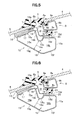
- the roof panel 4 and the seal member 27 have therebetween no distance as illustrated in FIG. 7 .
- FIG. 7 As shown in FIG.
- the rear portion of the seal attachment plate portion 23e of the side roof stiffener 23 is formed as an inclined surface 23f which gradually comes close to the roof panel 4 as extending to the rear end. Accordingly, in order to pressingly contact the seal member 24 inclinedly disposed on the inclined surface 23f, the rear portion of the lower surface portion 9c of the side panel holder 9 is formed as an inclined surface 9g (also see FIG. 11A ) which gradually comes close to the roof panel 4 as extending to the rear end, .
- the rear joint member 30 may be disposed at the rear of the side panel holder 9 and between the roof panel 4 and the seal member 24 as illustrated in FIG. 12A , which prevents formation of the above gap G.
- the lower surface of the rear joint member 30 is inclined, and the lower surface and the inclined surface 9g of the side panel holder 9 are flush with each other.
- the inclined surface 30b extends to the position where it comes in the vicinity of or in contact with the lower surface of the roof panel 4 (also see FIG. 11A ).
- This construction eliminates the gap G, and ensures a predetermined watertight function.
- the side panel holder 9 is a sheet metal member, and it is almost impossible to cut the rear end of the lower surface portion 9c at an acute angle so as not to produce a gap G.
- the rear joint member 30 is made of a resin material with excellent moldability, the rear end portion 30a of the rear joint member 30 is easily molded as a pointed portion with an acute angle.
- a guide frame 31 that extends in a front-rear direction of a vehicle is disposed at the lower side of both side edges of the roof panel 4.
- the guide frame 31 includes, in the cross section, a cable channel 33 for inserting a push-pull cable 32 that moves forward and rearward by using a diving motor (not shown).
- the guide frame 31 includes a guide rail channel 35 for guiding a drive slider 34, connecting to the push-pull cable 32 (the connection between both is not depicted), to be slid in a forward-rearward direction.
- the guide frame 31 is made of, for example, an extruded material of an aluminum-alloy.
- the drive slider 34 includes a main portion 34A of a vertical plate that stands along the guide frame 31.
- the drive slider 34 has a plurality of shoes 34B that project in a left- right direction from the lower portions of the front and rear ends of the main portion 34A and that can slide along the guide rail channel 35.
- the shoes 34B and the main portion 34A may be integrated, or may be separate members.
- the main portion 34A as illustrated in FIG. 2 , includes a first lift guide channel 36 and a second lift guide channel 37, which extend through the main portion 34A in a left-right direction, in the order from the front to the rear of the vehicle.
- the first lift guide channel 36 of a shape includes: a first horizontal stroke 36A that extends substantially horizontally; a first inclined stroke 36B that extends slightly inclinedly and upward from the front end of the first horizontal stroke 36A; a second horizontal stroke 36C that extends substantially horizontally and forward from the upper end of the first inclined stroke 36B; and a second inclined stroke 36D that extends inclinedly and upward from the front end of the second horizontal stroke 36C.
- the second lift guide channel 37 of a shape includes: a first horizontal stroke 37A that extends substantially horizontally; an inclined stroke 37B that extends inclinedly and upward from the front end of the first horizontal stroke 37A; and a second horizontal stroke 37C that extends substantially horizontally and forward from the upper end of the inclined stroke 37B.
- the roof panel 4 and the drive slider 34 have a panel support stay 38 interposed therebetween.
- the panel support stay 38 is a vertical plate member.
- the panel support stay 38 includes a base plate portion 39 which is formed at a front side and a forked portion 40 which is formed at a rear side.
- the forked portion 40 is constructed as a fork in such a manner that an upper-side portion 41 connecting to the roof panel 4 and a lower-side portion 42 engaging the drive slider 34 create an opening in a rearward direction.
- the upper-side portion 41 extends along the lower surface of the roof panel 4 in a substantially forward-rearward direction, and the rear end thereof is connected and fixed to one of connecting pins 43.
- the lower-side portion 42 also extends in a substantially forward-rearward direction, and the rear end thereof is fixed to a second lift guide pin 45 as described below.
- part of the side panel holder 9 is constructed as the vertical plate bracket portion 9f as described above. As illustrated in FIG. 2 , this bracket portion 9f is connected and fixed using a plurality of connecting pins 43 to the upper-side portion 41; and the upper edge portion of the base plate portion 39 of the panel support stay 38.
- a first lift guide pin 44 is fixed to the front end of the lower edge of the base plate portion 39 of the panel support stay 38.
- a second lift guide pin 45 is fixed to the rear end of the lower-side portion 42. The first lift guide pin 44 and the second lift guide pin 45 slidably engage the first lift guide channel 36 and the second lift guide channel 37, respectively, of the drive slider 34.
- panel support stay 38 and the side panel holder 9 may be integrated or the panel support stay 38 may be directly fixed with, for example, an adhesive to the lower surface of the roof panel 4 regardless of the side panel holder 9.
- FIGS. 8A and 8B and FIGS. 9A and 9B etc., the following describes the operation of the sunroof apparatus 1. Note that in FIGS. 8A and 8B and FIGS. 9A and 9B , the bracket portion 9f of the side panel holder 9 is omitted.
- FIG. 8A depicts a fully closed state of the roof panel 4. At that time, the drive slider 34 is at the most front position.
- the first lift guide pin 44 is positioned at the first horizontal stroke 36A of the first lift guide channel 36.
- the second lift guide pin 45 is positioned at the first horizontal stroke 37A of the second lift guide channel 37.
- the front panel holder 8 pressingly contacts the seal member 21.
- FIG. 8B depicts a state in which the tilt-up has been completed.
- the first lift guide pin 44 is positioned at the second horizontal stroke 36C of the first lift guide channel 36.
- the second lift guide pin 45 is positioned at the second horizontal stroke 37C of the second lift guide channel 37.
- the drive slider 34 further moves rearward from the state illustrated in FIG. 8B .
- the inner wall of the second inclined stroke 36D of the first lift guide channel 36 pushes the first lift guide pin 44 rearward, so that the roof panel 4 slides rearward.
- FIG. 9B depicts the fully open state of the opening portion 3 in which state the roof panel 4 moves to the most rear position.
- the upper-side portion 41 of the panel support stay 38 is positioned above a fixed roof 2 at the rear of the opening portion 3.
- the lower-side portion 42 is positioned below the fixed roof 2. That is, the fixed roof 2 at the rear of the opening portion 3 intervenes between the forked portions 40 of the panel support stay 38.
- FIG. 9B clearly demonstrates that the second lift guide pin 45 is positioned at the rear of the rear edge of the opening portion 3.
- JP-2005-41345A discloses a conventional structure in which when an opening portion is fully open, both two pins connecting a panel support stay and a slider are positioned in front of the rear edge of the opening portion. Unless the front end of a guide rail extends forward and the pin at a front side is positioned forward, it is difficult for this conventional structure to have an enough distance between two pins, namely, a support span to support roof panel's weight applied on the slider. In this conventional structure, the positions of two pins are shifted much more forward than the center of gravity of the roof panel. Thus, their moment becomes too large, and the panel support stay is likely to have more loads applied thereto.
- the second lift guide pin 45 is positioned at the rear of the rear edge of the opening portion 3. That is, the panel support stay 38, which is a part of supporting weight of the roof panel 4, and a part of an engaging portion of the drive slider 34 are positioned at the rear of the rear edge of the opening portion 3.
- This construction enables the support span S ( FIG. 3 ) of the roof panel 4 to be elongated while keeping a degree of opening of the opening portion 3 without taking a series of measures such as extending the front end of the guide frame 31 forward.
- a support portion to bear weight of the roof panel 4 is shifted more rearward than that of a conventional one to be positioned close to the center of gravity of the roof panel 4, which reduces a load applied to the panel support stay 38.
- the forked portion 40 is constructed like a fork in such a manner that an upper-side portion 41 fixed to the roof panel 4 and a lower-side portion 42 engaged with the drive slider 34 are used to create opening in a rear direction. As illustrated in FIG. 9B , when the opening portion 3 is fully open, the fixed roof 2 at the rear of the opening portion 3 is interposed between the forked portions 40.
- This structure enables the support span S of the roof panel 4 to be elongated while making the structure of the panel support stay 38 simple.
- the upper edge of the front window 5 is continuous to the front edge of the movable roof panel 4 without an outer roof board of the fixed roof 2 interposed therebetween.
- This construction allows for closure of the opening portion 3 of the roof. Then, this construction enlarges the visual field extending obliquely upward in a forward direction because there is no outer roof board between the front window 5 and the roof panel 4.
- a conventional technology e.g., JP-2010-163112A
- JP-2010-163112A discloses that a front roof rail is separated into two members (upper and lower members) which are welded using a flange portion. The flange portion tends to limit the visual field.
- the front roof rail 15 is constructed in such a way that one metal sheet is bent to form a substantially sectional closed structure. This construction does not need the flange portion, which further enlarges the visual field extending obliquely upward in a forward direction.
- the front roof rail 15 is constructed in such a way that at least a part (the front space 16a) of the sectional closed space 16 is placed immediately below the attachment portion of the front window 5. This construction sufficiently ensures a function of reinforcing the front window 5.
- the joint portion 17 between plates of the front roof rail 15 is closed by the patch member 18, which further enhances rigidity (mostly torsional rigidity) of the front roof rail 15.
- the adhesive 14 is used to adhere the front roof rail 15 to the front window 5. In this construction, if the joint portion 17 is closed with the adhesive 14, this simple structure increases rigidity of the front roof rail 15.
- the apparatus includes the front roof rail 15 with a structure in which at least part (the front space 16a) of the sectional closed space 16 is placed immediately below the attachment portion of the front window 5.
- the front lower portion of the front roof rail 15 has the inclined surface 15g that is inclined upward in a forward direction and whose upper end is at the most front position of the front roof rail 15.
- this construction makes it possible to ensure the visual line V1 from a seated person along the inclined surface 15g, which enlarges the visual field with regard to the front window 5.
- the front panel holder 8 pressingly contacts the seal member 21 at the front edge of the roof panel 4 and the lower surface of the roof panel 4 pressingly contacts the seal member 27 at the rear edge of the roof panel 4.
- This construction makes a vertical space of a seal structure around the rear edge of the roof panel 4 smaller than that of the structure in which the rear panel holder 10 pressingly contacts the seal member 27. This construction ensures a large head clearance.
- the apparatus includes the resin-made rear joint member 30 having the inclined surface 30b which is inclined upward as extending rearward with the rear end portion 30a coming in the vicinity of or in contact with the lower surface of the roof panel 4.
- the inclined surface 30b of the rear joint member 30 pressingly contacts the seal member 24 from the position of pressingly contacting the side panel holder 9 to the position of pressingly contacting the lower surface of the rear edge of the roof panel 4. This construction prevents occurrence of the gap G between the roof panel 4 and the seal member 24 as illustrated in FIG. 12B , which enhances watertightness of the seal member 24.
- the front roof stiffener 19 and the rear roof stiffener 26 include the drain channels 22 and 28, respectively.
- the seal members 21 and 27 serve as parts of channel walls of the drain channels 22 and 28. According to this construction, a part of the structure serves as the drain function and the watertight function of the roof panel. This construction makes the structure surrounding the drain channels 22 and 28 compact.
- the sectional shapes of the front roof stiffener 19 and the rear roof stiffener 26 become simple shapes.
- the seal member 24 may be a part of a channel wall of the drain channel 25.
- the drive slider 34 is constructed with a single body, but a slider may have separate units.
- the lower surface of the rear edge of the roof panel pressingly contacts the seal member, and a vertical space of a seal structure around the rear edge of the roof panel is reduced, which ensures a large head clearance.
- the sunroof apparatus prevents a gap between the roof panel and the seal member from occurring, and enhances watertightness of the seal member.
Landscapes
- Engineering & Computer Science (AREA)
- Mechanical Engineering (AREA)
- Body Structure For Vehicles (AREA)
- Seal Device For Vehicle (AREA)
Abstract
A sunroof apparatus (1) includes a movable roof panel (4), including a front edge connected to an upper edge of a front window (5) without a roof outer plate interposed between the roof panel (3) and the front window (5), for closing an opening portion (3) of a roof (2); a seal member (21,24,27) disposed at a circumference of an edge portion of the opening portion; a front panel holder (8) fixed to a lower surface of at least the front edge of the roof panel for reinforcing the roof panel (3), wherein during closing of the opening portion (3) of the roof (4), the front panel holder (8) pressingly contacts the seal member (21) disposed at the front edge of the roof panel (4), and a lower surface of the roof panel (4) pressingly contacts directly the seal member (27) disposed at a rear edge of the roof panel.
Description
- The present invention relates to a sunroof apparatus of a vehicle.
- A technology (see, for example,
JP2010-260393A - When the panel holder pressingly contacts the seal member, however, the panel holder and the seal member are arranged vertically in parallel with each other. As a result, the sunroof apparatus has an increased thickness in a height direction. Unfortunately, this construction tends to cause decreased head clearance in a vehicle interior.
- The present invention is directed to a sunroof apparatus having increased head clearance in a vehicle interior.
- An aspect of the invention provides a sunroof apparatus including a movable roof panel including a front edge connected to an upper edge of a front window without a roof outer plate interposed between the roof panel and the front window for closing an opening portion of a roof; a seal member disposed at a circumference of an edge portion of the opening portion; and a front panel holder fixed to a lower surface of at least the front edge of the roof panel for reinforcing the roof panel. During closing of the opening portion of the roof, the front panel holder pressingly contacts the seal member disposed at the front edge of the roof panel, and a lower surface of the roof panel pressingly contacts directly the seal member disposed at a rear edge of the roof panel.
- In the aspect of the invention, the roof panel includes a side edge fixed to a side panel holder and the rear edge fixed to a rear panel holder. During closing of the opening portion of the roof, the side panel holder pressingly contacts the seal member at the side edge of the roof panel. A rear end of the side panel holder and left and right ends of the rear panel holder are connected by a rear joint member. The rear joint member includes, on a lower surface thereof, an inclined surface which is inclined upward as extending rearward with a rear end thereof coming in the vicinity of or in contact with the lower surface of the roof panel. The inclined surface of the rear joint member pressingly contacts the seal member extending from a pressure-contact portion with the side panel holder to a pressure-contact portion with the lower surface of the rear edge of the roof panel.
- Certain preferred embodiments of the invention will now be described in greater detail by way of example only and with reference to the accompanying Figures, in which:
-
FIG. 1 is a plane view of a sunroof apparatus according to an embodiment of the present invention; -
FIG. 2 is a cross-sectional view taken along II-II ofFIG. 1 ; -
FIG. 3 is a side view of a panel support stay; -
FIG. 4 is a cross-sectional view taken along IV-IV ofFIG. 1 ; -
FIG. 5 is an enlarged sectional view illustrating a front edge portion of the roof panel ofFIG. 2 ; -
FIG. 6 is an enlarged sectional view illustrating a front edge portion of the roof panel ofFIG. 2 , and indicates a case with a patch member; -
FIG. 7 is an enlarged sectional view illustrating a rear edge portion of the roof panel ofFIG. 2 ; -
FIGS. 8A and 8B are side views illustrating operation of a sunroof apparatus according to an embodiment of the present invention operates; -
FIGS. 9A and 9B are side views illustrating operation of a sunroof apparatus according to an embodiment of the present invention; -
FIG. 10 illustrates condition of the visual field around a front roof rail when viewed from a side; -
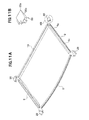
FIG. 11A is a perspective view illustrating appearance of respective front, side, and rear panel holders and front joint members and rear joint members connected to each panel holder; -
FIG. 11B is an enlarged perspective view illustrating a rear joint member as denoted by XIB inFIG. 11A ; and -
FIGS. 12A and 12B are side views illustrating a rear edge portion of a roof panel and depict a watertight state of a seal member.FIG. 12A shows the case with an interposed rear joint member.FIG. 12B shows the case without an interposed rear joint member. - In the Figures, VF denotes a forward direction of a vehicle, and VR denotes a rearward direction of the vehicle.
- As illustrated in
FIG. 1 , a sunroof apparatus 1 according to an embodiment of the present invention can be optionally open or closed with respect to anopening portion 3 of afixed roof 2 of a vehicle. The sunroof apparatus 1 includes an outer slidingroof panel 4 which is tilted up and moves rearward during the course of its opening. Theroof panel 4 is made of, for example, a glass or a resin panel. - The
opening portion 3 has a structure in which an outer roof board of thefixed roof 2 is rectangularly cut out from the front edge. Conventionally, a roof panel is continuous to the rear of the outer roof board when closed. In contrast, the left and right edges and the rear edge of a closedroof panel 4 shown inFIG. 1 are continuous to the outer roof board of thefixed roof 2. The front edge of theroof panel 4 is directly continuous to the upper edge of afront window 5 without the outer roof board therebetween. Strictly speaking, for example, arubber weatherstrip 6 fixed to the front edge of theroof panel 4 lightly contacts arubber weatherstrip 7 fixed to the upper edge of thefront window 5 as illustrated inFIG. 2 . Accordingly, the front edge of theroof panel 4 and the upper edge of thefront window 5 should be flush with each other. As shown inFIG. 5 , theweatherstrip 6 includes: abase portion 6a fixed to the front edge of theroof panel 4; and a thin tongue-shaped lip portion 6b extending forward from the front end of thebase portion 6a. The tip of thelip portion 6b of theweatherstrip 6 slightly contacts the upper rear surface portion of theweatherstrip 7. - In
FIG. 2 , in order to reinforce theroof panel 4, the lower surfaces of the front edge, side edges, and rear edge of theroof panel 4 have afront panel holder 8,side panel holders 9, and arear panel holder 10, respectively, installed by using, for example, adhesive. Thefront panel holder 8,side panel holders 9, andrear panel holder 10 are made of, for example, a metal member such as a galvanized steel sheet. - As illustrated in
FIG. 5 , thefront panel holder 8 includes, in the cross section, anupper surface portion 8a that extends slightly upward along the inclined surface of the front edge of theroof panel 4. Thefront panel holder 8 has arear surface portion 8b that extends downward from the rear end of theupper surface portion 8a that is substantially perpendicular to the panel plane of theroof panel 4. Thefront panel holder 8 has alower surface portion 8c that extends substantially horizontally and forward from the lower end of therear surface portion 8b. Thefront panel holder 8 has afront surface portion 8d that extends substantially horizontally and upward from the front end of thelower surface portion 8c that is substantially perpendicular to the panel plane of theroof panel 4. In addition, the upper end portion of thefront surface portion 8d is embedded in thebase portion 6a of theweatherstrip 6. The front end portion of theupper surface portion 8a is bent in a U-shape to be recessed in a downward direction, and engages with part of thebase portion 6a of theweatherstrip 6. As described above, thefront panel holder 8 is fixed to the lower surface of theroof panel 4 withweatherstrip 6 interposed therebetween. Meanwhile, theupper surface portion 8a of thefront panel holder 8 may be bonded with adhesive to the lower surface of theroof panel 4 as an additional or alternative structure. - As illustrated in
FIG. 4 , theside panel holder 9 includes, in the cross section, a firstupper surface portion 9a that is fixed with anadhesive 11 to the lower surface of the side edge of theroof panel 4. Theside panel holder 9 has a firstside surface portion 9b that extends from the end of the firstupper surface portion 9a at a center side in a vehicle widthwise direction, in a downward direction that is substantially perpendicular to the panel plane of theroof panel 4. Theside panel holder 9 has alower surface portion 9c that extends from the lower end of the firstside surface portion 9b and is in substantially parallel with the panel plane of theroof panel 4. In addition, thelower surface portion 9c is somewhat inclined upward toward a center side in the vehicle widthwise direction. Theside panel holder 9 has a secondside surface portion 9d that extends upward from the end of thelower surface portion 9c, which is at a center side in the vehicle widthwise direction. Theside panel holder 9 has a secondupper surface portion 9e that extends from the upper end of the secondside surface portion 9d toward the center in the vehicle widthwise direction and that attaches with adhesive 12 to the lower surface of theroof panel 4. Theside panel holder 9 has abracket portion 9f of a substantially vertical plate that extends downward from the end of the secondupper surface portion 9e at a center side in the vehicle widthwise direction. The firstside surface portion 9b, thelower surface portion 9c, and the secondside surface portion 9d, which are formed to make an enclosure with the lower surface of theroof panel 4, define a sectional closed space as a reinforcement function. Thebracket portion 9f is connected to a panel support stay 38 as described below. - As illustrated in
FIG. 7 , arear panel holder 10 includes, in the cross section, anupper surface portion 10a that attaches with adhesive 13 to the lower surface of the rear edge of theroof panel 4. Therear panel holder 10 has afront surface portion 10b that extends downward from the front end of theupper surface portion 10a. Therear panel holder 10 has alower surface portion 10c that extends in substantially parallel with the panel plane of theroof panel 4 and rearward from the lower end of thefront surface portion 10b. Therear panel holder 10 has arear surface portion 10d that extends upward from the rear end of thelower surface portion 10c and is connected to the rear end of theupper surface portion 10a. These four surfaces define an approximately rectangular sectional closed space. Therear panel holder 10 is fixed onto the lower surface that is positioned a little forward of the very end of the rear edge of theroof panel 4. - As illustrated in
FIG. 11A and 11B , frontjoint members 29 connect the front ends of theside panel holders 9 to both ends of thefront panel holder 8. Rearjoint members 30 connect the rear ends of theside panel holders 9 to both ends of therear panel holder 10. Each of the upper surfaces of the frontjoint members 29 and the rearjoint members 30 is appropriately bonded with, for example, adhesive to the lower surface of each of four corners of theroof panel 4. The frontjoint members 29 and the rearjoint members 30 are made of, for example, a resin material. - As illustrated in
FIG. 2 , afront roof rail 15 is installed using adhesive 14 on the inner surface of the upper edge of thefront window 5. Thefront roof rail 15 extends in a vehicle widthwise direction to retain strength of thefront window 5 and is a member having a substantially closed sectional structure. Thefront roof rail 15 is formed by bending, such as roll forming, of a metal plate (e.g., a galvanized steel sheet). - As illustrated in
FIG. 5 , thefront roof rail 15 includes, in the cross section, anattachment surface portion 15a which is bonded with adhesive 14 to the inner surface of the upper edge of thefront window 5. Thefront roof rail 15 has an upperrear surface portion 15b that extends downward from the rear end of theattachment surface portion 15a and is substantially perpendicular to the window plane of thefront window 5. Thefront roof rail 15 has an arc-shapedconcave portion 15c that is bent rearward and somewhat upward like a concave shape from the lower end of the upperrear surface portion 15b. Thefront roof rail 15 has asupport surface portion 15d that extends substantially horizontally and rearward from the rear end of theconcave portion 15c. Thefront roof rail 15 has a lowerrear surface portion 15e that extends substantially vertically and downward from the rear end of thesupport surface portion 15d. Thefront roof rail 15 has alower surface portion 15f that extends from the lower end of the lowerrear surface portion 15e and is inclined downward toward a front position. Thefront roof rail 15 has aninclined surface 15g that extends inclinedly from the front end of thelower surface portion 15f to a front position. The upper end of theinclined surface 15g is at the front end position of thefront roof rail 15, and is bent upward to be connected to the front end of theattachment surface portion 15a. - According to this outline of the
front roof rail 15, the sectional closedspace 16 of thefront roof rail 15 includes a narrowedportion 16c, in which theconcave portion 15c and theinclined surface 15g are disposed close to each other, as an interface on the whole. The sectional closedspace 16 includes afront space 16a and arear space 16b having the narrowedportion 16c defining a boundary therebetween. Thefront space 16a is surrounded mainly by theattachment surface portion 15a, the upperrear surface portion 15b, and theinclined surface 15g. Therear space 16b is surrounded mainly by thesupport surface portion 15d, the lowerrear surface portion 15e, and thelower surface portion 15f. Thefront space 16a is positioned immediately under theattachment surface portion 15a that is a portion fixed to thefront window 5. Therear space 16b is connected to the lower rear position in thefront space 16a, and is positioned under thefront panel holder 8, that is, under the front edge of theclosed roof panel 4. - As described above, the
front roof rail 15 is a member in which a single metal sheet is bent, so that ajoint portion 17 of the sheet is formed. Thefront roof rail 15 as shown inFIG. 5 is formed with ajoint portion 17 positioned at theattachment surface portion 15a. Thejoint portion 17 is closed with an adhesive 14, which increases rigidity of thefront roof rail 15. As an alternative example,FIG. 6 shows a structure in which apatch member 18, another member, is attached by welding to close thejoint portion 17. Note that in this case, it is unnecessary to close thejoint portion 17 withadhesive 14. Accordingly, thefront roof rail 15 may be formed with thejoint portion 17 which is positioned at a portion other than theattachment surface portion 15a. - Next, a drain channel for draining rain water, etc., is disposed under the perimeter of the
roof panel 4. First, as illustrated inFIG. 5 , afront roof stiffener 19 is disposed above thefront roof rail 15 and extends in a vehicle widthwise direction. Thefront roof stiffener 19 includes, in the cross section, abase plate portion 19a interposed between the upper edge of thefront window 5 and theattachment surface portion 15a of thefront roof rail 15. Thefront roof stiffener 19 has aside plate portion 19b that extends downward from the rear end of thebase plate portion 19a and is substantially perpendicular to the window plane of thefront window 5. Thefront roof stiffener 19 has abottom plate portion 19c that extends substantially horizontally and rearward from the lower end of theside plate portion 19b. Thefront roof stiffener 19 has a sealattachment plate portion 19d that extends rearward from the rear end of thebottom plate portion 19c. The sealattachment plate portion 19d is bent somewhat upward and extends substantially horizontally and rearward. The front end of thebase plate portion 19a of thefront roof stiffener 19 is fixed to thefront window 5 and theattachment surface portion 15a of thefront roof rail 15 with an adhesive 14. In thefront roof stiffener 19, the lower surface of each of thebottom plate portion 19c at a posterior side and the sealattachment plate portion 19d are fixed to thesupport surface portion 15d of thefront roof rail 15 with an adhesive 20. - A
seal member 21 that extends in a vehicle widthwise direction is fixed with, for example, an adhesive to the upper surface of the sealattachment plate portion 19d. Theseal member 21 is made of, for example, a hollow, closed, sectional rubber material. Thelower surface portion 8c of thefront panel holder 8 pressingly contacts theseal member 21 when closed. This makes the front edge portion of theroof panel 4 watertight to prevent water from infiltrating into a vehicle interior. That is, the front edge of theroof panel 4 is placed over therear space 16b of thefront roof rail 15 with thefront roof stiffener 19 interposed therebetween. Then, adrain channel 22 is defined by theside plate portion 19b, thebottom plate portion 19c, and aside surface 21a that is on a front side of theseal member 21. Water in thedrain channel 22 is drained via a front pillar through drain holes (not shown) that have been formed at or near both ends of thedrain channel 22 in the vehicle widthwise direction. - As illustrated in
FIG. 4 , aside roof stiffener 23 is disposed below a side edge of theroof panel 4 and extends in a front-rear direction of a vehicle. Theside roof stiffener 23 includes, in the cross section, a substantially horizontal connectingplate portion 23a that is connected to a vehicle framework (not shown). Theside roof stiffener 23 has a firstside plate portion 23b that extends substantially vertically and downward from an end of the connectingplate portion 23 a at a center side in the vehicle widthwise direction. Theside roof stiffener 23 has abottom plate portion 23c that extends substantially horizontally toward a center side in the vehicle widthwise direction from the lower end of the firstside plate portion 23b. Theside roof stiffener 23 has a secondside plate portion 23d that extends substantially vertically and upward from an end of thebottom plate portion 23c at a center side in the vehicle widthwise direction. Theside roof stiffener 23 has a sealattachment plate portion 23e that extends inclinedly and somewhat upward from the upper end of the secondside plate portion 23d toward a center side in the vehicle widthwise direction. - A
seal member 24 that extends in a front-rear direction of the vehicle is fixed with, for example, an adhesive to the upper surface of the sealattachment plate portion 23e. Note that thisseal member 24, theabove seal member 21, and a below-describedseal member 27 are members that are integrated as a rectangular frame. Thelower surface portion 9c of theside panel holder 9 pressingly contacts theseal member 24 when closed. This makes the side edge portion of theroof panel 4 watertight to prevent water from infiltrating into a vehicle interior. Then, adrain channel 25 is defined by the firstside plate portion 23b, thebottom plate portion 23c, and the secondside plate portion 23d. Water in thedrain channel 25 is drained via, for example, a front pillar and/or a center pillar through a drain hole (not shown). - As illustrated in
FIG. 7 , arear roof stiffener 26 is disposed below the rear edge of theroof panel 4 and extends in the vehicle widthwise direction. Note that thisrear roof stiffener 26, the abovefront roof stiffener 19, and theside roof stiffeners 23 are members which are integrated as a rectangular frame. Therear roof stiffener 26 includes, in the cross section, a substantially horizontal connectingplate portion 26a that is connected to a vehicle framework (not shown). Therear roof stiffener 26 has aside plate portion 26b that extends downward from the front end of the connectingplate portion 26a. Therear roof stiffener 26 has abottom plate portion 26c that extends substantially horizontally and forward from the lower end of theside plate portion 26b. Therear roof stiffener 26 has a sealattachment plate portion 26d that extends forward from the front end of thebottom plate portion 26c. The sealattachment plate portion 26d is bent somewhat upward and extends forward and substantially horizontally. - The upper surface of the seal
attachment plate portion 26d has aseal member 27 that extends in the vehicle widthwise direction fixed thereto with, for example, an adhesive. When theroof panel 4 is closed, thefront panel holder 8 and theside panel holder 9 pressingly contact theseal members roof panel 4. With regard to the rear edge of theroof panel 4, therear panel holder 10 does not pressingly contact theseal member 27. The lower surface of the rear edge of theroof panel 4 pressingly contacts theseal member 27. This makes the rear edge portion of theroof panel 4 watertight to prevent water from infiltrating into a vehicle interior. Then, adrain channel 28 is defined by theside plate portion 26b, thebottom plate portion 26c, and aside surface 27a that is on a rear side of theseal member 27. Water in thedrain channel 28 is drained via a center pillar through drain holes (not shown) that has been formed at or near both ends of thedrain channel 28 in the widthwise direction. - Here, with regard to the rear edge of the
roof panel 4, the following problem arises due to the structure in which theseal member 27 directly and pressingly contacts the lower surface of theroof panel 4 without therear panel holder 10 interposed therebetween. As illustrated inFIG. 4 , at the side edge of theroof panel 4, theside panel holder 9 pressingly contacts theseal member 24. Accordingly, theroof panel 4 and theseal member 24 have therebetween a distance corresponding to a height of theside panel holder 9. In contrast, theroof panel 4 and theseal member 27 have therebetween no distance as illustrated inFIG. 7 . As shown inFIG. 12A , the rear portion of the sealattachment plate portion 23e of theside roof stiffener 23 is formed as aninclined surface 23f which gradually comes close to theroof panel 4 as extending to the rear end. Accordingly, in order to pressingly contact theseal member 24 inclinedly disposed on theinclined surface 23f, the rear portion of thelower surface portion 9c of theside panel holder 9 is formed as aninclined surface 9g (also seeFIG. 11A ) which gradually comes close to theroof panel 4 as extending to the rear end, . - If the
side panel holder 9 extends rearward without modification as illustrated inFIG. 12B , a plate thickness of thelower surface portion 9c causes a gap G among the rear end of thelower surface portion 9c, theroof panel 4, and theseal member 24. This may result in an insufficient watertight condition. In contrast, the rearjoint member 30 may be disposed at the rear of theside panel holder 9 and between theroof panel 4 and theseal member 24 as illustrated inFIG. 12A , which prevents formation of the above gap G. The lower surface of the rearjoint member 30 is inclined, and the lower surface and theinclined surface 9g of theside panel holder 9 are flush with each other. In addition, theinclined surface 30b extends to the position where it comes in the vicinity of or in contact with the lower surface of the roof panel 4 (also seeFIG. 11A ). This construction eliminates the gap G, and ensures a predetermined watertight function. Theside panel holder 9 is a sheet metal member, and it is almost impossible to cut the rear end of thelower surface portion 9c at an acute angle so as not to produce a gap G. In contrast, if the rearjoint member 30 is made of a resin material with excellent moldability, therear end portion 30a of the rearjoint member 30 is easily molded as a pointed portion with an acute angle. - The following describes an opening-closing mechanism of the
roof panel 4. InFIG. 4 , aguide frame 31 that extends in a front-rear direction of a vehicle is disposed at the lower side of both side edges of theroof panel 4. Theguide frame 31 includes, in the cross section, acable channel 33 for inserting a push-pull cable 32 that moves forward and rearward by using a diving motor (not shown). Theguide frame 31 includes aguide rail channel 35 for guiding adrive slider 34, connecting to the push-pull cable 32 (the connection between both is not depicted), to be slid in a forward-rearward direction. Theguide frame 31 is made of, for example, an extruded material of an aluminum-alloy. - The
drive slider 34 includes amain portion 34A of a vertical plate that stands along theguide frame 31. Thedrive slider 34 has a plurality ofshoes 34B that project in a left- right direction from the lower portions of the front and rear ends of themain portion 34A and that can slide along theguide rail channel 35. Theshoes 34B and themain portion 34A may be integrated, or may be separate members. Themain portion 34A, as illustrated inFIG. 2 , includes a firstlift guide channel 36 and a secondlift guide channel 37, which extend through themain portion 34A in a left-right direction, in the order from the front to the rear of the vehicle. - The first
lift guide channel 36 of a shape includes: a firsthorizontal stroke 36A that extends substantially horizontally; a firstinclined stroke 36B that extends slightly inclinedly and upward from the front end of the firsthorizontal stroke 36A; a secondhorizontal stroke 36C that extends substantially horizontally and forward from the upper end of the firstinclined stroke 36B; and a secondinclined stroke 36D that extends inclinedly and upward from the front end of the secondhorizontal stroke 36C. The secondlift guide channel 37 of a shape includes: a firsthorizontal stroke 37A that extends substantially horizontally; aninclined stroke 37B that extends inclinedly and upward from the front end of the firsthorizontal stroke 37A; and a secondhorizontal stroke 37C that extends substantially horizontally and forward from the upper end of theinclined stroke 37B. - The
roof panel 4 and thedrive slider 34 have a panel support stay 38 interposed therebetween. With reference toFIGS. 2 and3 , the panel support stay 38 is a vertical plate member. The panel support stay 38 includes abase plate portion 39 which is formed at a front side and a forkedportion 40 which is formed at a rear side. The forkedportion 40 is constructed as a fork in such a manner that an upper-side portion 41 connecting to theroof panel 4 and a lower-side portion 42 engaging thedrive slider 34 create an opening in a rearward direction. The upper-side portion 41 extends along the lower surface of theroof panel 4 in a substantially forward-rearward direction, and the rear end thereof is connected and fixed to one of connecting pins 43. The lower-side portion 42 also extends in a substantially forward-rearward direction, and the rear end thereof is fixed to a secondlift guide pin 45 as described below. - In
FIG. 4 , part of theside panel holder 9 is constructed as the verticalplate bracket portion 9f as described above. As illustrated inFIG. 2 , thisbracket portion 9f is connected and fixed using a plurality of connectingpins 43 to the upper-side portion 41; and the upper edge portion of thebase plate portion 39 of thepanel support stay 38. In addition, a firstlift guide pin 44 is fixed to the front end of the lower edge of thebase plate portion 39 of thepanel support stay 38. A secondlift guide pin 45 is fixed to the rear end of the lower-side portion 42. The firstlift guide pin 44 and the secondlift guide pin 45 slidably engage the firstlift guide channel 36 and the secondlift guide channel 37, respectively, of thedrive slider 34. - Note that the panel support stay 38 and the
side panel holder 9 may be integrated or the panel support stay 38 may be directly fixed with, for example, an adhesive to the lower surface of theroof panel 4 regardless of theside panel holder 9. - With reference to
FIGS. 8A and 8B andFIGS. 9A and 9B , etc., the following describes the operation of the sunroof apparatus 1. Note that inFIGS. 8A and 8B andFIGS. 9A and 9B , thebracket portion 9f of theside panel holder 9 is omitted.FIG. 8A depicts a fully closed state of theroof panel 4. At that time, thedrive slider 34 is at the most front position. The firstlift guide pin 44 is positioned at the firsthorizontal stroke 36A of the firstlift guide channel 36. The secondlift guide pin 45 is positioned at the firsthorizontal stroke 37A of the secondlift guide channel 37. In the front edge of theroof panel 4, thefront panel holder 8 pressingly contacts theseal member 21. In the side edge of theroof panel 4, theside panel holder 9 pressingly contacts the seal member 24 (seeFIG. 4 ). In the rear edge of theroof panel 4, the lower surface of theroof panel 4 pressingly contacts theseal member 27. This construction keeps theroof panel 4 watertight. - A motor (not shown) is actuated and the
drive slider 34 moves rearward using the push-pull cable 32 (FIG. 4 ) from the state illustrated inFIG. 8A . At that time, the inner wall of the firstinclined stroke 36B of the firstlift guide channel 36 lifts the firstlift guide pin 44. Together with that, the inner wall of theinclined stroke 37B of the secondlift guide channel 37 lifts the secondlift guide pin 45. Consequently, theroof panel 4 somewhat moves rearward and is tilted up.FIG. 8B depicts a state in which the tilt-up has been completed. The firstlift guide pin 44 is positioned at the secondhorizontal stroke 36C of the firstlift guide channel 36. The secondlift guide pin 45 is positioned at the secondhorizontal stroke 37C of the secondlift guide channel 37. - The
drive slider 34 further moves rearward from the state illustrated inFIG. 8B . At that time, as illustrated inFIG. 9A , the inner wall of the secondinclined stroke 36D of the firstlift guide channel 36 pushes the firstlift guide pin 44 rearward, so that theroof panel 4 slides rearward. -
FIG. 9B depicts the fully open state of theopening portion 3 in which state theroof panel 4 moves to the most rear position. The upper-side portion 41 of the panel support stay 38 is positioned above afixed roof 2 at the rear of theopening portion 3. The lower-side portion 42 is positioned below the fixedroof 2. That is, the fixedroof 2 at the rear of theopening portion 3 intervenes between the forkedportions 40 of thepanel support stay 38.FIG. 9B clearly demonstrates that the secondlift guide pin 45 is positioned at the rear of the rear edge of theopening portion 3. -
JP-2005-41345A - In contrast, in the present structure, when the
opening portion 3 is fully open, the secondlift guide pin 45 is positioned at the rear of the rear edge of theopening portion 3. That is, thepanel support stay 38, which is a part of supporting weight of theroof panel 4, and a part of an engaging portion of thedrive slider 34 are positioned at the rear of the rear edge of theopening portion 3. This construction enables the support span S (FIG. 3 ) of theroof panel 4 to be elongated while keeping a degree of opening of theopening portion 3 without taking a series of measures such as extending the front end of theguide frame 31 forward. In addition, a support portion to bear weight of theroof panel 4 is shifted more rearward than that of a conventional one to be positioned close to the center of gravity of theroof panel 4, which reduces a load applied to thepanel support stay 38. - Further, as a shape of the
panel support stay 38, the forkedportion 40 is constructed like a fork in such a manner that an upper-side portion 41 fixed to theroof panel 4 and a lower-side portion 42 engaged with thedrive slider 34 are used to create opening in a rear direction. As illustrated inFIG. 9B , when theopening portion 3 is fully open, the fixedroof 2 at the rear of theopening portion 3 is interposed between the forkedportions 40. This structure enables the support span S of theroof panel 4 to be elongated while making the structure of the panel support stay 38 simple. - As described above, with regard to the sunroof apparatus 1, the upper edge of the
front window 5 is continuous to the front edge of themovable roof panel 4 without an outer roof board of the fixedroof 2 interposed therebetween. This construction allows for closure of theopening portion 3 of the roof. Then, this construction enlarges the visual field extending obliquely upward in a forward direction because there is no outer roof board between thefront window 5 and theroof panel 4. In addition, a conventional technology (e.g.,JP-2010-163112A front roof rail 15 according to this embodiment is constructed in such a way that one metal sheet is bent to form a substantially sectional closed structure. This construction does not need the flange portion, which further enlarges the visual field extending obliquely upward in a forward direction. Thefront roof rail 15 is constructed in such a way that at least a part (thefront space 16a) of the sectional closedspace 16 is placed immediately below the attachment portion of thefront window 5. This construction sufficiently ensures a function of reinforcing thefront window 5. - The
joint portion 17 between plates of thefront roof rail 15 is closed by thepatch member 18, which further enhances rigidity (mostly torsional rigidity) of thefront roof rail 15. In this embodiment, the adhesive 14 is used to adhere thefront roof rail 15 to thefront window 5. In this construction, if thejoint portion 17 is closed with the adhesive 14, this simple structure increases rigidity of thefront roof rail 15. - When the
opening portion 3 is closed, the front edge of theroof panel 4 is placed over the sectional closedspace 16 of thefront roof rail 15, specifically, over therear space 16b. This construction makes it possible to effectively bear loads from theroof panel 4 because of a rigidity function of the sectional closedspace 16. There is no need to create an additional flange portion, etc., for placing the front edge of theroof panel 4. This makes a placement space compact. As illustrated inFIG. 10 , a small intersecting angle θ between the visual line V1 and the visual line V2 enlarges the visual field extending obliquely upward in a forward direction. - The apparatus includes the
front roof rail 15 with a structure in which at least part (thefront space 16a) of the sectional closedspace 16 is placed immediately below the attachment portion of thefront window 5. In this case, the front lower portion of thefront roof rail 15 has theinclined surface 15g that is inclined upward in a forward direction and whose upper end is at the most front position of thefront roof rail 15. As illustrated inFIG. 10 , this construction makes it possible to ensure the visual line V1 from a seated person along theinclined surface 15g, which enlarges the visual field with regard to thefront window 5. - When the
opening portion 3 is closed, thefront panel holder 8 pressingly contacts theseal member 21 at the front edge of theroof panel 4 and the lower surface of theroof panel 4 pressingly contacts theseal member 27 at the rear edge of theroof panel 4. This construction makes a vertical space of a seal structure around the rear edge of theroof panel 4 smaller than that of the structure in which therear panel holder 10 pressingly contacts theseal member 27. This construction ensures a large head clearance. - As illustrated in
FIG. 12A , the apparatus includes the resin-made rearjoint member 30 having theinclined surface 30b which is inclined upward as extending rearward with therear end portion 30a coming in the vicinity of or in contact with the lower surface of theroof panel 4. Theinclined surface 30b of the rearjoint member 30 pressingly contacts theseal member 24 from the position of pressingly contacting theside panel holder 9 to the position of pressingly contacting the lower surface of the rear edge of theroof panel 4. This construction prevents occurrence of the gap G between theroof panel 4 and theseal member 24 as illustrated inFIG. 12B , which enhances watertightness of theseal member 24. - The
front roof stiffener 19 and therear roof stiffener 26 include thedrain channels seal members drain channels drain channels front roof stiffener 19 and therear roof stiffener 26 become simple shapes. Of course, with regard to theside roof stiffener 23, theseal member 24 may be a part of a channel wall of thedrain channel 25. - Hereinabove, preferred embodiments of the present invention have been described. In the embodiments described, the
drive slider 34 is constructed with a single body, but a slider may have separate units. - According to the sunroof apparatus, the lower surface of the rear edge of the roof panel pressingly contacts the seal member, and a vertical space of a seal structure around the rear edge of the roof panel is reduced, which ensures a large head clearance.
- The sunroof apparatus prevents a gap between the roof panel and the seal member from occurring, and enhances watertightness of the seal member.
Claims (2)
- A sunroof apparatus (1) comprising:a movable roof panel (4), including a front edge connectable to an upper edge of a front window (5) without a roof outer plate interposed between the roof panel and the front window, for closing an opening portion (3) of a roof (2);a seal member (21,24,27) disposed at a circumference of an edge portion of the opening portion; anda front panel holder (8) fixed to a lower surface of at least the front edge of the roof panel for reinforcing the roof panel,wherein the sunroof apparatus is arranged such that, during closing of the opening portion of the roof, the front panel holder pressingly contacts the seal member disposed at the front edge of the roof panel, and a lower surface of the roof panel pressingly contacts directly the seal member disposed at a rear edge of the roof panel.
- The sunroof apparatus according to Claim 1,
wherein the roof panel includes a side edge fixed to a side panel holder (9) and the rear edge is fixed to a rear panel holder (10),
wherein the sunroof apparatus is arranged such that, during closing of the opening portion of the roof, the side panel holder pressingly contacts the seal member at the side edge of the roof panel,
wherein a rear end of the side panel holder and left and right ends of the rear panel holder are connected by a rear joint member (30),
wherein the rear joint member includes, on a lower surface thereof, an inclined surface which is inclined upward as extending rearward with a rear end thereof coming in the vicinity of or in contact with the lower surface of the roof panel, and
wherein the inclined surface of the rear joint member is arranged to pressingly contact the seal member extending from a pressure-contact portion with the side panel holder to a pressure-contact portion with the lower surface of the rear edge of the roof panel.
Applications Claiming Priority (1)
| Application Number | Priority Date | Filing Date | Title |
|---|---|---|---|
| JP2012183043A JP2014040166A (en) | 2012-08-22 | 2012-08-22 | Sunroof device |
Publications (1)
| Publication Number | Publication Date |
|---|---|
| EP2700525A2 true EP2700525A2 (en) | 2014-02-26 |
Family
ID=49028968
Family Applications (1)
| Application Number | Title | Priority Date | Filing Date |
|---|---|---|---|
| EP13181426.1A Withdrawn EP2700525A2 (en) | 2012-08-22 | 2013-08-22 | Sunroof apparatus |
Country Status (4)
| Country | Link |
|---|---|
| US (1) | US8915542B2 (en) |
| EP (1) | EP2700525A2 (en) |
| JP (1) | JP2014040166A (en) |
| CN (1) | CN103625252B (en) |
Families Citing this family (7)
| Publication number | Priority date | Publication date | Assignee | Title |
|---|---|---|---|---|
| DE102014206059A1 (en) * | 2014-03-31 | 2015-10-01 | SMF Vertriebs GmbH | Roof module and vehicle with housing device comprising a roof module |
| US9290084B2 (en) * | 2014-05-30 | 2016-03-22 | GM Global Technology Operations LLC | Modular sunroof frame assembly and method |
| JP6561781B2 (en) * | 2015-11-06 | 2019-08-21 | アイシン精機株式会社 | Sunroof device |
| DE102015120408B3 (en) * | 2015-11-25 | 2017-03-09 | Webasto SE | Cover of a vehicle roof with insert in a plastic mold section |
| CN105744230A (en) * | 2016-03-04 | 2016-07-06 | 南京协才电子科技有限公司 | Vehicle-mounted driving see-through system |
| DE102020116910A1 (en) | 2020-06-26 | 2021-12-30 | Bayerische Motoren Werke Aktiengesellschaft | Vehicle roof as well as vehicle |
| US11697330B2 (en) * | 2021-11-24 | 2023-07-11 | AISIN Technical Center of America, Inc. | Perimeter frame for a sunshade module |
Family Cites Families (6)
| Publication number | Priority date | Publication date | Assignee | Title |
|---|---|---|---|---|
| US4729596A (en) * | 1986-04-08 | 1988-03-08 | Nissan Motor Co., Ltd. | Vehicle roof structure having left and right removable roof lids |
| US5950366A (en) * | 1997-04-21 | 1999-09-14 | General Motors Corporation | Seal structure for removable roof |
| CN100393541C (en) * | 2002-01-21 | 2008-06-11 | 本田技研工业株式会社 | car sunroof system |
| JP4647450B2 (en) * | 2005-09-27 | 2011-03-09 | 豊田合成株式会社 | Weather strip |
| JP4313398B2 (en) * | 2007-03-29 | 2009-08-12 | 八千代工業株式会社 | Deflector mechanism of vehicle sunroof device |
| JP2010260393A (en) | 2009-04-30 | 2010-11-18 | Toyoda Gosei Co Ltd | Roof weather strip for automobile |
-
2012
- 2012-08-22 JP JP2012183043A patent/JP2014040166A/en active Pending
-
2013
- 2013-08-20 CN CN201310364334.2A patent/CN103625252B/en active Active
- 2013-08-21 US US13/972,251 patent/US8915542B2/en active Active
- 2013-08-22 EP EP13181426.1A patent/EP2700525A2/en not_active Withdrawn
Also Published As
| Publication number | Publication date |
|---|---|
| JP2014040166A (en) | 2014-03-06 |
| US20140054932A1 (en) | 2014-02-27 |
| US8915542B2 (en) | 2014-12-23 |
| CN103625252B (en) | 2016-02-10 |
| CN103625252A (en) | 2014-03-12 |
Similar Documents
| Publication | Publication Date | Title |
|---|---|---|
| EP2700525A2 (en) | Sunroof apparatus | |
| JP5631944B2 (en) | Sunroof device | |
| US7963070B2 (en) | Slider window for pick-up truck, and/or method of making the same | |
| CN101934710B (en) | Interlocking mechanism of sunshade panel in a sunroof device | |
| EP2607126B1 (en) | Glass-run retainer for automobile door and door structure of automobile | |
| CN103625253B (en) | Skylight device | |
| EP2700524A2 (en) | Sunroof device | |
| CN105329322A (en) | Center pillar structure | |
| JP5631945B2 (en) | Sunroof device | |
| JP5973889B2 (en) | Sunroof device | |
| EP3050728A1 (en) | Sealing structure for non-fixed type roof | |
| JP2014040165A (en) | Sunroof device | |
| WO2014080927A1 (en) | Deflector structure of sunroof device | |
| CN101274586A (en) | frame for sunroof | |
| JP2006131152A (en) | Guide frame structure in sunroof device | |
| JP2014040164A (en) | Sunroof device | |
| CN204432563U (en) | The car window decorative strip of vehicle | |
| JP5194085B2 (en) | Sunroof device | |
| JPH1120474A (en) | Guide rail in sliding roof device of vehicle | |
| JP2005041362A (en) | Sunroof panel mounting structure | |
| JP2007091161A (en) | Car body rear structure | |
| EP1270386A1 (en) | Car roof panel provided with fixed glass | |
| JPH11321330A (en) | Sunroof frame structure |
Legal Events
| Date | Code | Title | Description |
|---|---|---|---|
| PUAI | Public reference made under article 153(3) epc to a published international application that has entered the european phase |
Free format text: ORIGINAL CODE: 0009012 |
|
| AK | Designated contracting states |
Kind code of ref document: A2 Designated state(s): AL AT BE BG CH CY CZ DE DK EE ES FI FR GB GR HR HU IE IS IT LI LT LU LV MC MK MT NL NO PL PT RO RS SE SI SK SM TR |
|
| AX | Request for extension of the european patent |
Extension state: BA ME |
|
| STAA | Information on the status of an ep patent application or granted ep patent |
Free format text: STATUS: THE APPLICATION HAS BEEN WITHDRAWN |
|
| 18W | Application withdrawn |
Effective date: 20150615 |