US4729596A - Vehicle roof structure having left and right removable roof lids - Google Patents
Vehicle roof structure having left and right removable roof lids Download PDFInfo
- Publication number
- US4729596A US4729596A US07/035,420 US3542087A US4729596A US 4729596 A US4729596 A US 4729596A US 3542087 A US3542087 A US 3542087A US 4729596 A US4729596 A US 4729596A
- Authority
- US
- United States
- Prior art keywords
- latch
- lids
- roof
- center beam
- latch plates
- Prior art date
- Legal status (The legal status is an assumption and is not a legal conclusion. Google has not performed a legal analysis and makes no representation as to the accuracy of the status listed.)
- Expired - Fee Related
Links
Images


Classifications
-
- B—PERFORMING OPERATIONS; TRANSPORTING
- B60—VEHICLES IN GENERAL
- B60J—WINDOWS, WINDSCREENS, NON-FIXED ROOFS, DOORS, OR SIMILAR DEVICES FOR VEHICLES; REMOVABLE EXTERNAL PROTECTIVE COVERINGS SPECIALLY ADAPTED FOR VEHICLES
- B60J7/00—Non-fixed roofs; Roofs with movable panels, e.g. rotary sunroofs
- B60J7/08—Non-fixed roofs; Roofs with movable panels, e.g. rotary sunroofs of non-sliding type, i.e. movable or removable roofs or panels, e.g. let-down tops or roofs capable of being easily detached or of assuming a collapsed or inoperative position
- B60J7/10—Non-fixed roofs; Roofs with movable panels, e.g. rotary sunroofs of non-sliding type, i.e. movable or removable roofs or panels, e.g. let-down tops or roofs capable of being easily detached or of assuming a collapsed or inoperative position readily detachable, e.g. tarpaulins with frames, or fastenings for tarpaulins
- B60J7/106—Non-fixed roofs; Roofs with movable panels, e.g. rotary sunroofs of non-sliding type, i.e. movable or removable roofs or panels, e.g. let-down tops or roofs capable of being easily detached or of assuming a collapsed or inoperative position readily detachable, e.g. tarpaulins with frames, or fastenings for tarpaulins readily detachable hard-tops
Definitions
- the present invention relates to a fastening means for securing left and right removable roof lids of an open-top type vehicle roof structure.
- FIGS. 16 and 17 One conventional example of such roof structures is shown in FIGS. 16 and 17.
- This roof structure belongs to a type called T-bar roof (for example, in "Jidosha Kogaku Zensho", published by Sankaido, vol. 13, page 158.)
- a roof 302 of a vehicle body 301 shown in FIG. 16 an exterior roof surface is formed by upper surfaces of a longitudinal center beam 303, and left and right removable glass lids 305 fitted in left and right roof openings 304.
- Each lid 305 is removably secured to the vehicle body by a lock device 311 provided on the outboard side of each lid 305, and at least one hooked latch plate 310 fixed to the inboard end of each lid 305, as shown in FIG. 17.
- FIG. 17 further shows a roof inner panel 312, and retainers 313 attached to peripheries of the lids 305.
- the center beam 303 of this roof structure is always exposed to view, so that the upper surface of the center beam must be finished in the same manner as the remaining part of the roof surface.
- FIGS. 18-20 Another conventional example is shown in FIGS. 18-20.
- a roof structure of this example is similar to what is disclosed in Japanese patent provisional publication No. 59-186735.
- a vehicle roof frame structure 401 shown in FIG. 18 has a longitudinal center beam 402 separating left and right roof openings 403.
- Front and rear receiving members 404 each having left and right latch holes 405 are fixed to the top of the center beam 402 by screws 406.
- Front and rear latch plates 408 are fixed to the underside of each of left and right roof lids 407 by screws 409, and inserted, respectively, in the left or right latch holes 405 of the front and rear receiving members 404 in the closed state, as shown in FIG. 20.
- Each lid 407 is locked by lock rods 410 which can be projected into lock holes 411 formed in the frame structure and retracted by manual operation.
- Each of the roof openings 403 is fringed with a weatherstrip 421 for abutting against the underside of one of the lids 407.
- the inner ends of the left and right lids 407 abut, literally or nearly, on each other above the receiving members 404. Therefore, the center beam 402 of this example is concealed under the roof surface in the closed state.
- a roof structure of a vehicle comprises a frame structure, left and right removable roof lids, and fastening means.
- the frame structure has a front portion, a rear portion, and a center beam extending along a longitudinal axis of the vehicle and connecting the front and rear portions.
- the frame structure further has left and right roof openings formed between the front and rear portions, and separated by the center beam.
- the left and right roof lids can close the left and right roof openings, respectively, to form a closed roof surface, and conceal the center beam under the closed roof surface when the left and right lids are placed in respective left and right closed positions.
- the fastening means is for securing the left and right lids in the left and right closed positions to the frame structure.
- the fastening means comprises left and right latch means, and receiving means.
- the left and right latch means are fixed, respectively, to undersides of the left and right lids.
- the receiving means is fixedly mounted on an upper surface of the center beam, and formed with left and right latch holes for receiving the left and right latch means, respectively, when the lids are placed in the closed positions.
- each of the latch holes is bounded on an upper side by a downward flange, and each of the latch means is formed with an upward flange which is inserted in one of the latch holes when the lids are placed in the closed positions.
- each of the left and right latch means comprises a first latch plate having a raised portion fixed to the underside of one of the lids, and a depressed portion which projects from the raised portion to a projected end, and which is L-shaped and formed with a hollow corner formed by the angle of the L-shaped figure of the depressed portion so that the hollow corner of one of the latch plates of the left and right lids receives the projected end of the other of the latch plates when the lids are placed in the closed positions.
- FIG. 1 is a perspective view of a roof structure for showing a first embodiment of the present invention.
- FIG. 2 is a perspective view of the roof structure of FIG. 1 with left and right roof lids in closed positions.
- FIG. 3 is a perspective view of a set of a receiving member, and left and right latch plates, used in the roof structure of FIG. 1.
- FIG. 4 is a sectional view taken on a line IV--IV of FIG. 3, for showing the left and right latch plates in the receiving member in the closed state of the left and right lids.
- FIG. 5 is a sectional view taken on a line V--V of FIG. 4, for showing the latch plate in an improper position.
- FIG. 6 is a sectional view taken on a line VI--VI of FIG. 2.
- FIG. 7 is a sectional view taken on a line VII--VII of FIG. 2.
- FIG. 8 is a sectional view taken on a line VIII--VIII of FIG. 2.
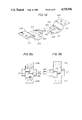
- FIG. 9 is a sectional view of a main portion of a roof structure for showing a second embodiment of the present invention.
- FIG. 10 is a sectional view of a main portion of a roof structure for showing a third embodiment of the present invention.
- FIG. 11 is a perspective view of a latch plate used in the roof structure of FIG. 10.
- FIG. 12 is a sectional view of the latch plate, taken on a line XII--XII of FIG. 11.
- FIG. 13 is a schematic plan view of the roof lid used in the roof structure of FIG. 10, for showing the positions of guide covers.
- FIG. 14 is a perspective view of a pair of latch plates used in a roof structure of a fourth embodiment of the preent invention.
- FIG. 15 is a sectional view similar to FIG. 4, but showing the fourth embodiment.
- FIG. 16 is a perspective view of a vehicle for showing a roof structure of one conventional example.
- FIG. 17 is a sectional view taken on a line XVII--XVII of FIG. 16.
- FIG. 18 is a perspective view showing a roof structure of another conventional example.
- FIG. 19 is a sectional view taken on a line XIX--XIX of FIG. 18.
- FIG. 20 is a sectional view taken on a line XX--XX of FIG. 18.
- FIGS. 1-8 A first embodiment of the present invention is shown in FIGS. 1-8.
- An open-top type roof structure of the first embodiment has a frame structure 20 which is a part of a vehicle body.
- the frame structure 20 has a front portion 21F, a rear portion 21R and a longitudinal center beam 22 extending along the longitudinal axis of the vehicle in such a manner as to bisect the roof into left and right halves, and connecting the front and rear portions 21F and 21R.
- the frame structure 20 has left and right roof openings 23 which are separated by the center beam 22, and bounded between the front and rear portions 21F and 21R.
- the center beam 22 is placed at a level lower than upper surfaces of the front and rear portions 21F and 21R.
- the left and right roof openings 23 are closed up when left and right roof lids 24 are placed in respective closed positions, in which the left and right lids 24 are fitted in the left and right openings 23, respectively, as shown in FIG. 2.
- inner end of the left and right lids 24 substantially abut on each other along a line immediately above the center beam 22, and a continuous exterior roof surface is formed by the left and right lids 24 and the front and rear portions 21F and 21R of the frame structure 20.
- the center beam 22 is concealed under the roof surface formed by the left and right lids 24.
- the roof structure further has fastening means for securing the left and right lids 24 to the frame structure 20.
- the fastening means includes the following constituent members. Front and rear receiving members 26 are fixed to a top of the center beam 22. Each of the receiving members 26 projects upwardly from the center beam 22, and has left and right latch holes 31. The front receiving member 26 is positioned near the front portion 21F, and the rear receiving member 26 is near the rear portion 21R. Front and rear latch plates 25, and a lock device 27 are fixed to an underside of each lid 24. Each lid 24 is placed in its closed position by inserting the front and rear latch plates 25 into the left or right latch holes 31 of the front and rear receiving members 26, respectively.
- Each of the latch plates 25 has a first end fixed to the underside of the lid 24 near the inner end of the lid 24, and a free second end.
- the front and rear latch plates 25 extend from their respective first ends, substantially along the lateral axis of the vehicle toward the center beam 22, to their respective second ends received in the latch holes of the front and rear receiving members 26.
- the lock device 27 of each lid 24 is positioned near the outer end of the lid 24, and has front and rear lock rods 28 for locking and unlocking the lid 24.
- the front and rear lock rods 28 are projected toward the front and rear of the vehicle, respectively, and engaged with front and rear lock holes formed in the front and rear portions 21F and 21R, respectively.
- Each lid 24 can be unlocked by retracting the front and rear lock rods 28.
- each receiving member 26 has left and right flat mounting portions 29, and a central portion 30 lying between the left and right portions 29.
- the central portion 30 of each receiving member 26 has left and right side wall extending upwardly, respectively, from the left and right mounting portions 29, and a substantially flat top wall extending between the left and right side walls.
- the left and right side walls are substantially vertical, and face toward the left and right sides of the vehicle, respectively.
- the left latch hole 31 is formed in the left side wall, and the right latch hole 31 is in the right side wall, in each receiving member 26.
- the top wall of the central portion of each receiving member 26 is covered with a molding 32 of resin.
- Each of the latch plates 25 has a raised portion 33 which is fixed to the underside of one of the lids 24 by bolts, and a depressed portion 34 covered with a molding of resin. When the lids 24 are placed in the closed positions, the depressed portion 34 of each latch plate 25 is inserted in one of the latch holes 31.
- the depressed portion 34 is L-shaped, and has a projecting portion projecting from the raised portion 33 and having a length L as shown in FIG. 3, and rectangular hollow corner formed by the angle of the L-shaped figure.
- the depressed portion of one latch plate 25 has the L-shaped figure reverse to that of the other latch plate 25 so that the hollow corner is situated behind the projecting portion in one latch plate 25 while the projecting portion is situated behind the hollow corner in the other latch plate 25.
- each latch plate 25 When both lids 24 are placed in the closed positions, the projecting portion of each latch plate 25 is snugly received in the hollow corner of the opposite latch plate 25 in each of the front and rear receiving members 26, as shown in FIG. 4. In this way, each latch plate 25 is deeply inserted to or beyond the center line of the receiving member 26, and securely installed in one of the receiving members 26 together with the opposite latch plate 25 without mutual interference. With the long and deeply inserted latch plates 25, the left and right lids 24 are secured to the frame structure 20 very reliably.
- Each of the front and rear receiving members 26 has an upright projection 35 projecting upwardly from the top of the receiving member 26 and extending along the longitudinal axis of the vehicle.
- the upright projection 35 of each receiving member 26 is formed in the molding 32, as shown in FIG. 5.
- each of the left and right roof lids 24 is composed of an outer panel 40 and an inner panel 41. At least one weatherstrip 42 is attached to the periphery of each lid 24.
- Each of the center beam 22, and the front and rear portions of the frame structure 20 is composed of an outer panel 44, an inner panel 45 and a reinforcing panel 46.
- the center beam 22 is provided with weatherstrips 47 which extend along the longitudinal axis of the vehicle and about on the weatherstrips 42 of the left and right lids 24.
- Each of the left and right roof openings 23 is fringed with at least one weatherstrip 48 mounted on upward flanges of the outer panels 44 of the frame structure 20 for abutting on the underside of the lid 24, and at least one drip channel 49 formed in the outer panels 44 for directing rainwater off. Projecting edges of the inner panels 45 of the frame structure 20 are covered with decorative welts 50.
- the vehicle body further includes a front window glass (windshield glass) 51, a molding 52 covering a gap between the front window glass 51 and the outer panel 44, a layer of adhesive 53 for fastening the front window glass 52 to the vehicle body, and a dam of rubber 54.
- the center beam is concealed under the roof surface when the lids are placed in the closed positions. Therefore, the roof structure of the present invention can improve the appearance of the roof surface, and curtail the finishing operations of the center beam.
- a second embodiment of the present invention is shown in FIG. 9.
- a roof structure of the second embodiment is basically identical to the structure of the first embodiment, but different in the following points.
- Each of left and right roof lids 55 of the second embodiment is made of glass.
- Each of latch plates 56 of the second embodiment is shaped like a hook, and fixed to the inner end of one of the lids 55.
- At least one pair of left and right hook-shaped receiving members 62 are fixed, by screw fasteners 61, to a center beam 60 which is composed of an outer panel 57, an inner panel 58 and a reinforcing panel 59, and concealed under the roof surface.
- the lids 55 are placed in the closed positions by inserting the left and right latch plates 56 of the left and right lids 55, respectively, in the concavities of the left and right receiving members 62, as shown in FIG. 9.
- each receiving member is simplified in design.
- FIGS. 10-13 A third embodiment of the present invention is shown in FIGS. 10-13.
- a roof structure of the third embodiment has a frame structure substantially identical to that of the first embodiment.
- front and rear receiving members 104 each having left and right latch holes 105 are fixedly mounted on a longitudinal center beam 102, and front and rear latch plates 108 are fixed to the underside of each of left and right roof lids 107 near the inner end, as shown in FIG. 10.
- each of the latch plates 108 of the third embodiment has an upward flange 116 formed at the projecting end of the latch plate 108, and each receiving members 104 has left and right downward flanges 115 forming upper borders of the left and right latch holes 105, respectively.
- Each of the upward and downward flanges 116 and 115 extends substantially along the longitudinal axis of the vehicle when the lids 107 are placed in the closed positions.
- a front or rear half of the upward flange 116 is covered by a guide cover 117 of resin.
- the guide cover 117 of each latch plate 108 has a top wall having a substantially flat upper surface. One end of each guide cover 117 is formed with a cut 118.
- Each guide cover 117 is fixed to the latch plate 108 by inserting the upward flange 116 in the cut 118, and using adhesive bonding, for example.
- Each latch plate 108 has a raised portion fixed to the underside of one of the lids 107, and a depressed portion which is depressed between the upward flange 116 and the raised portion and which has a substantially flat bottom in the illustrated example.
- the top wall of the guide cover 117 extends from the top end of the upward flange to the raised portion substantially in parallel to the bottom of the depressed portion, and covers a half of the depressed portion.
- Each guide cover 117 has a boxlike cross sectional shape, so that a hollow space is formed between the top wall of the guide cover 117 and the bottom of the depressed portion of the latch plate 108, as shown in FIG. 12.
- the top wall of each guide cover 117 is substantially horizontal when the lids 107 are placed in the closed position, and the vehicle is on a level road.
- the guide cover 117 of one latch plate 108 is positioned over the front half of the depressed portion, and the guide cover 117 of the other latch plate 108 is positioned over the rear half of the depressed portion.
- the third embodiment as shown in FIG.
- the front latch plate 108 of each lid 107 has the guide cover 117 covering the front half of the depressed portion
- the rear latch plate 108 has the cover 117 covering the rear half of the depressed portion.
- the guide covers 117 of each lid 107 facilitate the insertion and extraction of the latch plates 108 into and from the receiving members 104 when the lid 107 is put in the closed position, and removed.
- the guide covers 117 prevent the engagement between the upward flanges 116 and the downward flanges 115 by allowing the downward flanges 115 to slide relatively on the upper surfaces of the guide covers 117.
- the lid 107 When an excessive load is applied upwardly from the passenger compartment to one lid 107 placed in its closed position, the lid 107 is bent to bulge outwardly, and accordingly the latch plates 108 are extracted in an upwardly sloping direction.
- the guide covers 117 are pressed against the downward flanges 115, and easily deformed elastically. Therefore, the downward flanges 115 of the receiving members 104 prevent the extraction of the latch plates 108 by engaging with the upward flanges 116 of the latch plates 108.
- the upward and downward flanges 116 and 115 of the third embodiment can improve the safety by preventing undesired release of the lids 107.
- the roof structure of the third embodiment incurs neither increase in the manufacturing cost nor increase in the weight of the vehicle.
- a fourth embodiment of the present invention is shown in FIGS. 14 and 15.
- a roof structure of the fourth embodiment has a frame structure substantially identical to those of the preceding embodiments.
- each of front and rear receiving members of the fourth embodiment is formed with left and right downward flanges forming upper borders of the left and right latch holes, and fixedly mounted on the center beam.
- Each of the latch plates 208 of the fourth embodiment has an upward flange 216 and a guide cover 217 like the third embodiment, and further has a hollow corner 220 like the first embodiment.
- Each latch plate 208 has a raised portion 221 fixed to the underside of one of the lids, and a depressed portion 222 depressed between the raised portion 221 and the upward flange 216.
- each latch plate 208 is L-shaped, and the rectangular hollow corner 220 is formed by the angle of the L-shaped figure.
- the guide cover 217 covers only a front or rear half of the upward flange 216, and extends from the top of the upward flange 216 to the raised portion 221.
- the depressed portion of one latch plate 208 has the L-shaped figure reverse to that of the other latch plate 208, like the first embodiment.
- each latch plate 208 When both lids are placed in the closed positions, the upward flange 216 of each latch plate 208 is deeply inserted in one receiving member to or beyond the center line of the receiving member, and received in the deep part of the hollow corner 220 of the opposite latch plate 208, as shown in FIG. 15.
- FIG. 15 the front latch plates 208 of the left and right lids received in the front receiving member are shown on the left side of FIG. 15, and the rear latch plates 208 received in the rear receiving member are shown on the right.
- the cover 217 is placed at such a position as to cover the front half of the upward flange 216.
- the cover 217 is placed at such a position as to cover the rear half of the upward flange 216.
- the cover 217 is situated in the middle between the front and rear sides of the latch plate 208 to prevent interference between the upward flanges in the front receiving member, and a notch 224 is formed in the rear side of the latch plate 208 behind the upward flange 216.
- the cover 217 is situated in the middle to prevent interference between the upward flanges 216 in the rear receiving member, and a notch 224 is formed in the front side of the latch plate behind the upward flange 216.
- Each notch 224 facilitates engagement between the upward and downward flanges when an excessive load is applied upwardly to the lid.
Landscapes
- Engineering & Computer Science (AREA)
- Mechanical Engineering (AREA)
- Body Structure For Vehicles (AREA)
Abstract
Description
Claims (13)
Applications Claiming Priority (4)
| Application Number | Priority Date | Filing Date | Title |
|---|---|---|---|
| JP61080481A JPH0692208B2 (en) | 1986-04-08 | 1986-04-08 | Detachable rufrid connection structure |
| JP61-80481 | 1986-04-08 | ||
| JP61-93261 | 1986-04-24 | ||
| JP61093261A JPH0696370B2 (en) | 1986-04-24 | 1986-04-24 | Vehicle openable roof structure |
Publications (1)
| Publication Number | Publication Date |
|---|---|
| US4729596A true US4729596A (en) | 1988-03-08 |
Family
ID=26421482
Family Applications (1)
| Application Number | Title | Priority Date | Filing Date |
|---|---|---|---|
| US07/035,420 Expired - Fee Related US4729596A (en) | 1986-04-08 | 1987-04-07 | Vehicle roof structure having left and right removable roof lids |
Country Status (1)
| Country | Link |
|---|---|
| US (1) | US4729596A (en) |
Cited By (25)
| Publication number | Priority date | Publication date | Assignee | Title |
|---|---|---|---|---|
| US4940283A (en) * | 1989-07-31 | 1990-07-10 | Androy Gilbert G | T-top roofing system |
| US5042873A (en) * | 1986-06-13 | 1991-08-27 | Nissan Motor Co., Ltd. | Detachable roof structure for automotive vehicle |
| US5052743A (en) * | 1988-10-20 | 1991-10-01 | Nissan Motor Co., Ltd. | Open-top type vehicle roof structure |
| USD374651S (en) | 1995-01-13 | 1996-10-15 | Townsend Kevin P | Pair of T-top covers for two-seater sports car |
| GB2328910A (en) * | 1997-09-05 | 1999-03-10 | Daimler Benz Ag | Roof arrangement comprising two roof parts |
| US6039391A (en) * | 1995-08-15 | 2000-03-21 | Suzuki Motor Corporation | Hatch roof attaching construction for a T-bar roof car |
| US6332645B1 (en) * | 1998-07-10 | 2001-12-25 | Webasto Karosseriesysteme Gmbh | Sealing arrangement for a motor vehicle sliding roof, sliding and lifting roof, spoiler roof, louvered roof or the like |
| US6644728B1 (en) * | 1999-10-29 | 2003-11-11 | Aisin Seiki Kabushiki Kaisha | Sunroof device |
| EP1422098A1 (en) * | 2002-11-20 | 2004-05-26 | Dr.Ing. h.c.F. Porsche Aktiengesellschaft | Removable roof for a vehicle |
| US20070001486A1 (en) * | 2005-06-30 | 2007-01-04 | Dowdey Christopher C | Removable T-top stowage on roof rack |
| FR2894883A1 (en) * | 2005-12-20 | 2007-06-22 | Renault Sas | MOTOR VEHICLE HAVING REMOVABLE SUNSCREENS TO A CENTRAL PART OF A ROOF OF SAID VEHICLE |
| US20080203769A1 (en) * | 2003-06-03 | 2008-08-28 | Winfried Bunsmann | Folding Top for a Motor Vehicle |
| FR2915142A1 (en) * | 2007-04-19 | 2008-10-24 | Heuliez Sa | Vehicle i.e. car, has water collector arranged in junction area between roof and resistant fixed structure to collect water from roof when roof covers passenger compartment, and ring seal arranged between parts of collector |
| US20090102229A1 (en) * | 2007-10-19 | 2009-04-23 | Magna Car Top Systems Gmbh | Retractable Hardtop with Two-Piece Rear Section and Removable Front Roof Panels |
| WO2009077065A1 (en) * | 2007-12-19 | 2009-06-25 | Daimler Ag | Roof structure of a body of a motor vehicle |
| US20110031782A1 (en) * | 2009-08-01 | 2011-02-10 | Daimler Ag | Method of Mounting a Roof Element as well as a Mounting Arrangement of a Roof Element |
| US20130285409A1 (en) * | 2012-04-27 | 2013-10-31 | Honda Motor Co., Ltd. | Seal structure for door of automobile |
| US20140035328A1 (en) * | 2012-07-31 | 2014-02-06 | Dr. Ing. H.C. F. Porsche Aktiengesellschaft | Removable roof for a motor vehicle, and motor vehicle |
| US20140054932A1 (en) * | 2012-08-22 | 2014-02-27 | Yachiyo Industry Co., Ltd. | Sunroof apparatus |
| US8752887B2 (en) * | 2012-08-29 | 2014-06-17 | Hyundai Motor Company | Hybrid combination structure of roof frame |
| US9931920B1 (en) * | 2016-12-09 | 2018-04-03 | Ford Global Technologies, Llc | Vehicle roof assembly |
| DE102007060487B4 (en) | 2007-12-14 | 2022-08-11 | Magna Car Top Systems Gmbh | Foldable roof for a passenger car |
| US20220266662A1 (en) * | 2021-02-19 | 2022-08-25 | Gentex Corporation | Connection methods for power removable and/or movable dimmable device |
| US20230028850A1 (en) * | 2021-07-20 | 2023-01-26 | Teijin Automotive Technologies, Inc. | Removable vehicle side panel system |
| CN116001542A (en) * | 2021-10-21 | 2023-04-25 | 通用汽车环球科技运作有限责任公司 | Bottom loading removable roof panel system |
Citations (3)
| Publication number | Priority date | Publication date | Assignee | Title |
|---|---|---|---|---|
| US4428155A (en) * | 1982-01-15 | 1984-01-31 | Le Van Specialty Co., Inc. | Releasable hinge device for removable panels |
| JPS59186735A (en) * | 1983-03-08 | 1984-10-23 | Mazda Motor Corp | Dismoutable car roof |
| US4626026A (en) * | 1983-08-23 | 1986-12-02 | Nissan Shatai Company, Limited | Automotive roof structure with a detachable set roof |
-
1987
- 1987-04-07 US US07/035,420 patent/US4729596A/en not_active Expired - Fee Related
Patent Citations (3)
| Publication number | Priority date | Publication date | Assignee | Title |
|---|---|---|---|---|
| US4428155A (en) * | 1982-01-15 | 1984-01-31 | Le Van Specialty Co., Inc. | Releasable hinge device for removable panels |
| JPS59186735A (en) * | 1983-03-08 | 1984-10-23 | Mazda Motor Corp | Dismoutable car roof |
| US4626026A (en) * | 1983-08-23 | 1986-12-02 | Nissan Shatai Company, Limited | Automotive roof structure with a detachable set roof |
Non-Patent Citations (2)
| Title |
|---|
| "Jidosha Kogaku Zensho", published by Sankaido, vol. 13, p. 158. |
| Jidosha Kogaku Zensho , published by Sankaido, vol. 13, p. 158. * |
Cited By (48)
| Publication number | Priority date | Publication date | Assignee | Title |
|---|---|---|---|---|
| US5042873A (en) * | 1986-06-13 | 1991-08-27 | Nissan Motor Co., Ltd. | Detachable roof structure for automotive vehicle |
| US5052743A (en) * | 1988-10-20 | 1991-10-01 | Nissan Motor Co., Ltd. | Open-top type vehicle roof structure |
| US4940283A (en) * | 1989-07-31 | 1990-07-10 | Androy Gilbert G | T-top roofing system |
| USD374651S (en) | 1995-01-13 | 1996-10-15 | Townsend Kevin P | Pair of T-top covers for two-seater sports car |
| US6039391A (en) * | 1995-08-15 | 2000-03-21 | Suzuki Motor Corporation | Hatch roof attaching construction for a T-bar roof car |
| GB2328910A (en) * | 1997-09-05 | 1999-03-10 | Daimler Benz Ag | Roof arrangement comprising two roof parts |
| GB2328910B (en) * | 1997-09-05 | 1999-10-20 | Daimler Benz Ag | Roof arrangement comprising two roof parts |
| US6059356A (en) * | 1997-09-05 | 2000-05-09 | Daimlerchrysler Ag | Two part roof arrangement |
| US6332645B1 (en) * | 1998-07-10 | 2001-12-25 | Webasto Karosseriesysteme Gmbh | Sealing arrangement for a motor vehicle sliding roof, sliding and lifting roof, spoiler roof, louvered roof or the like |
| US6644728B1 (en) * | 1999-10-29 | 2003-11-11 | Aisin Seiki Kabushiki Kaisha | Sunroof device |
| EP1422098A1 (en) * | 2002-11-20 | 2004-05-26 | Dr.Ing. h.c.F. Porsche Aktiengesellschaft | Removable roof for a vehicle |
| US20040150253A1 (en) * | 2002-11-20 | 2004-08-05 | Bodo Homann | Removable roof assembly for a motor vehicle |
| US6929318B2 (en) | 2002-11-20 | 2005-08-16 | Dr. Ing. H.C.F. Porsche Aktiengesellschaft | Removable roof assembly for a motor vehicle |
| US20080203769A1 (en) * | 2003-06-03 | 2008-08-28 | Winfried Bunsmann | Folding Top for a Motor Vehicle |
| US7712825B2 (en) * | 2003-06-03 | 2010-05-11 | Wilhelm Karmann Gmbh | Folding top for a motor vehicle |
| US20070001486A1 (en) * | 2005-06-30 | 2007-01-04 | Dowdey Christopher C | Removable T-top stowage on roof rack |
| US7213854B2 (en) | 2005-06-30 | 2007-05-08 | Asc Incorporated | Removable T-top stowage on roof rack |
| FR2894883A1 (en) * | 2005-12-20 | 2007-06-22 | Renault Sas | MOTOR VEHICLE HAVING REMOVABLE SUNSCREENS TO A CENTRAL PART OF A ROOF OF SAID VEHICLE |
| EP1800924A1 (en) | 2005-12-20 | 2007-06-27 | Renault s.a.s. | Sun visor which is stowed in a longitudinal central roof beam |
| FR2915142A1 (en) * | 2007-04-19 | 2008-10-24 | Heuliez Sa | Vehicle i.e. car, has water collector arranged in junction area between roof and resistant fixed structure to collect water from roof when roof covers passenger compartment, and ring seal arranged between parts of collector |
| US7896423B2 (en) * | 2007-10-19 | 2011-03-01 | Magna Car Top Systems Gmbh | Retractable hardtop with two-piece rear section and removable front roof panels |
| US20090102229A1 (en) * | 2007-10-19 | 2009-04-23 | Magna Car Top Systems Gmbh | Retractable Hardtop with Two-Piece Rear Section and Removable Front Roof Panels |
| DE102007060487B4 (en) | 2007-12-14 | 2022-08-11 | Magna Car Top Systems Gmbh | Foldable roof for a passenger car |
| US20110012390A1 (en) * | 2007-12-19 | 2011-01-20 | Daimler Ag | Roof Structure of a Body of a Motor Vehicle |
| US8398160B2 (en) | 2007-12-19 | 2013-03-19 | Daimler Ag | Roof structure of a body of a motor vehicle |
| WO2009077065A1 (en) * | 2007-12-19 | 2009-06-25 | Daimler Ag | Roof structure of a body of a motor vehicle |
| US20110031782A1 (en) * | 2009-08-01 | 2011-02-10 | Daimler Ag | Method of Mounting a Roof Element as well as a Mounting Arrangement of a Roof Element |
| US8196999B2 (en) * | 2009-08-01 | 2012-06-12 | Daimler Ag | Method of mounting a roof element as well as a mounting arrangement of a roof element |
| US20130285409A1 (en) * | 2012-04-27 | 2013-10-31 | Honda Motor Co., Ltd. | Seal structure for door of automobile |
| US8882186B2 (en) * | 2012-04-27 | 2014-11-11 | Nishikawa Rubber Co., Ltd | Seal structure for door of automobile |
| CN103568792B (en) * | 2012-07-31 | 2016-07-13 | F·波尔希名誉工学博士公司 | Removable roofs for motor vehicles, and motor vehicles |
| DE102012106968B4 (en) | 2012-07-31 | 2023-11-23 | Dr. Ing. H.C. F. Porsche Aktiengesellschaft | Removable roof for a motor vehicle and motor vehicle |
| US8979183B2 (en) * | 2012-07-31 | 2015-03-17 | Dr. Ing. H.C.F. Porsche Aktiengesellschaft | Removable roof for a motor vehicle, and motor vehicle |
| CN103568792A (en) * | 2012-07-31 | 2014-02-12 | F·波尔希名誉工学博士公司 | Removable roof for motor vehicle, and motor vehicle |
| US20140035328A1 (en) * | 2012-07-31 | 2014-02-06 | Dr. Ing. H.C. F. Porsche Aktiengesellschaft | Removable roof for a motor vehicle, and motor vehicle |
| US20140054932A1 (en) * | 2012-08-22 | 2014-02-27 | Yachiyo Industry Co., Ltd. | Sunroof apparatus |
| US8915542B2 (en) * | 2012-08-22 | 2014-12-23 | Yachiyo Industry Co., Ltd. | Sunroof apparatus |
| CN103625252B (en) * | 2012-08-22 | 2016-02-10 | 八千代工业株式会社 | Skylight device |
| CN103625252A (en) * | 2012-08-22 | 2014-03-12 | 八千代工业株式会社 | Sunroof apparatus |
| US8752887B2 (en) * | 2012-08-29 | 2014-06-17 | Hyundai Motor Company | Hybrid combination structure of roof frame |
| US9931920B1 (en) * | 2016-12-09 | 2018-04-03 | Ford Global Technologies, Llc | Vehicle roof assembly |
| US20220266662A1 (en) * | 2021-02-19 | 2022-08-25 | Gentex Corporation | Connection methods for power removable and/or movable dimmable device |
| US12358352B2 (en) * | 2021-02-19 | 2025-07-15 | Gentex Corporation | Connection methods for power removable and/or movable dimmable device |
| US20230028850A1 (en) * | 2021-07-20 | 2023-01-26 | Teijin Automotive Technologies, Inc. | Removable vehicle side panel system |
| US11999219B2 (en) * | 2021-07-20 | 2024-06-04 | Teijin Automotive Technologies, Inc. | Removable vehicle side panel system |
| CN116001542A (en) * | 2021-10-21 | 2023-04-25 | 通用汽车环球科技运作有限责任公司 | Bottom loading removable roof panel system |
| US20230131621A1 (en) * | 2021-10-21 | 2023-04-27 | Gm Global Technology Operations Llc. | Bottom load removable roof panel system |
| US11667178B2 (en) * | 2021-10-21 | 2023-06-06 | GM Global Technology Operations LLC | Bottom load removable roof panel system |
Similar Documents
| Publication | Publication Date | Title |
|---|---|---|
| US4729596A (en) | Vehicle roof structure having left and right removable roof lids | |
| US4626026A (en) | Automotive roof structure with a detachable set roof | |
| US6378936B1 (en) | Vehicle roof | |
| EP0366045B1 (en) | Roof panel mounting structure | |
| US4679847A (en) | Removable cab top for vehicles | |
| US4120529A (en) | Removable roof panels for vehicles | |
| JP2008081108A (en) | Automotive roof frame | |
| US4666206A (en) | Sunroof frame assembly for vehicles | |
| US20040094992A1 (en) | Vehicle roof module | |
| GB2099377A (en) | Improvements in detachable hard-tops for vehicles | |
| US4606573A (en) | Convertible roof conversion kit | |
| US6039391A (en) | Hatch roof attaching construction for a T-bar roof car | |
| US5104177A (en) | Cap for conversion van | |
| US4046278A (en) | Air cargo container | |
| US6203100B1 (en) | Sport-utility vehicle top | |
| US4512598A (en) | Releasable latch bracket means for a vehicle sunroof | |
| US5609387A (en) | Lining panel for a sliding roof for a vehicle | |
| US3294436A (en) | Vehicle body trim support | |
| US4275915A (en) | Vehicle closure | |
| JPS59190021A (en) | Construction of car roof | |
| JPH0565027A (en) | Frame structure for sun roof | |
| JP3562606B2 (en) | Roof jumping car | |
| CN219727831U (en) | High-strength automobile skylight guide rail | |
| JPS6018979Y2 (en) | car door waterproofing device | |
| JPH0724269Y2 (en) | Guide rails for automobile sunshades |
Legal Events
| Date | Code | Title | Description |
|---|---|---|---|
| AS | Assignment |
Owner name: NISSAN MOTOR CO., LTD. NO. 2, TAKARA-CHO, KANAGAWA Free format text: ASSIGNMENT OF ASSIGNORS INTEREST.;ASSIGNORS:FUJIHARA, RYOJI;FURUSE, KAZUAKI;ISHIZUKA, SATOSHI;AND OTHERS;REEL/FRAME:004727/0241 Effective date: 19870511 Owner name: NISSAN MOTOR CO., LTD.,JAPAN Free format text: ASSIGNMENT OF ASSIGNORS INTEREST;ASSIGNORS:FUJIHARA, RYOJI;FURUSE, KAZUAKI;ISHIZUKA, SATOSHI;AND OTHERS;REEL/FRAME:004727/0241 Effective date: 19870511 |
|
| FEPP | Fee payment procedure |
Free format text: PAYOR NUMBER ASSIGNED (ORIGINAL EVENT CODE: ASPN); ENTITY STATUS OF PATENT OWNER: LARGE ENTITY |
|
| FPAY | Fee payment |
Year of fee payment: 4 |
|
| FEPP | Fee payment procedure |
Free format text: PAYOR NUMBER ASSIGNED (ORIGINAL EVENT CODE: ASPN); ENTITY STATUS OF PATENT OWNER: LARGE ENTITY Free format text: PAYER NUMBER DE-ASSIGNED (ORIGINAL EVENT CODE: RMPN); ENTITY STATUS OF PATENT OWNER: LARGE ENTITY |
|
| FPAY | Fee payment |
Year of fee payment: 8 |
|
| REMI | Maintenance fee reminder mailed | ||
| LAPS | Lapse for failure to pay maintenance fees | ||
| FP | Lapsed due to failure to pay maintenance fee |
Effective date: 20000308 |
|
| STCH | Information on status: patent discontinuation |
Free format text: PATENT EXPIRED DUE TO NONPAYMENT OF MAINTENANCE FEES UNDER 37 CFR 1.362 |