EP2700457B1 - Squeeze roll stand - Google Patents
Squeeze roll stand Download PDFInfo
- Publication number
- EP2700457B1 EP2700457B1 EP11863940.0A EP11863940A EP2700457B1 EP 2700457 B1 EP2700457 B1 EP 2700457B1 EP 11863940 A EP11863940 A EP 11863940A EP 2700457 B1 EP2700457 B1 EP 2700457B1
- Authority
- EP
- European Patent Office
- Prior art keywords
- movable portion
- fixed portion
- roll stand
- rolls
- squeeze roll
- Prior art date
- Legal status (The legal status is an assumption and is not a legal conclusion. Google has not performed a legal analysis and makes no representation as to the accuracy of the status listed.)
- Not-in-force
Links
Images

Classifications
-
- B—PERFORMING OPERATIONS; TRANSPORTING
- B21—MECHANICAL METAL-WORKING WITHOUT ESSENTIALLY REMOVING MATERIAL; PUNCHING METAL
- B21B—ROLLING OF METAL
- B21B31/00—Rolling stand structures; Mounting, adjusting, or interchanging rolls, roll mountings, or stand frames
- B21B31/08—Interchanging rolls, roll mountings, or stand frames, e.g. using C-hooks; Replacing roll chocks on roll shafts
- B21B31/14—Interchanging rolls, roll mountings, or stand frames, e.g. using C-hooks; Replacing roll chocks on roll shafts by pivotally displacing
-
- B—PERFORMING OPERATIONS; TRANSPORTING
- B21—MECHANICAL METAL-WORKING WITHOUT ESSENTIALLY REMOVING MATERIAL; PUNCHING METAL
- B21D—WORKING OR PROCESSING OF SHEET METAL OR METAL TUBES, RODS OR PROFILES WITHOUT ESSENTIALLY REMOVING MATERIAL; PUNCHING METAL
- B21D5/00—Bending sheet metal along straight lines, e.g. to form simple curves
- B21D5/06—Bending sheet metal along straight lines, e.g. to form simple curves by drawing procedure making use of dies or forming-rollers, e.g. making profiles
- B21D5/10—Bending sheet metal along straight lines, e.g. to form simple curves by drawing procedure making use of dies or forming-rollers, e.g. making profiles for making tubes
- B21D5/12—Bending sheet metal along straight lines, e.g. to form simple curves by drawing procedure making use of dies or forming-rollers, e.g. making profiles for making tubes making use of forming-rollers
-
- B—PERFORMING OPERATIONS; TRANSPORTING
- B21—MECHANICAL METAL-WORKING WITHOUT ESSENTIALLY REMOVING MATERIAL; PUNCHING METAL
- B21B—ROLLING OF METAL
- B21B13/00—Metal-rolling stands, i.e. an assembly composed of a stand frame, rolls, and accessories
- B21B13/001—Convertible or tiltable stands, e.g. from duo to universal stands, from horizontal to vertical stands
-
- B—PERFORMING OPERATIONS; TRANSPORTING
- B21—MECHANICAL METAL-WORKING WITHOUT ESSENTIALLY REMOVING MATERIAL; PUNCHING METAL
- B21C—MANUFACTURE OF METAL SHEETS, WIRE, RODS, TUBES, PROFILES OR LIKE SEMI-MANUFACTURED PRODUCTS OTHERWISE THAN BY ROLLING; AUXILIARY OPERATIONS USED IN CONNECTION WITH METAL-WORKING WITHOUT ESSENTIALLY REMOVING MATERIAL
- B21C37/00—Manufacture of metal sheets, rods, wire, tubes, profiles or like semi-manufactured products, not otherwise provided for; Manufacture of tubes of special shape
- B21C37/06—Manufacture of metal sheets, rods, wire, tubes, profiles or like semi-manufactured products, not otherwise provided for; Manufacture of tubes of special shape of tubes or metal hoses; Combined procedures for making tubes, e.g. for making multi-wall tubes
- B21C37/08—Making tubes with welded or soldered seams
- B21C37/0807—Tube treating or manipulating combined with, or specially adapted for use in connection with tube making machines, e.g. drawing-off devices, cutting-off
- B21C37/0811—Tube treating or manipulating combined with, or specially adapted for use in connection with tube making machines, e.g. drawing-off devices, cutting-off removing or treating the weld bead
-
- B—PERFORMING OPERATIONS; TRANSPORTING
- B21—MECHANICAL METAL-WORKING WITHOUT ESSENTIALLY REMOVING MATERIAL; PUNCHING METAL
- B21C—MANUFACTURE OF METAL SHEETS, WIRE, RODS, TUBES, PROFILES OR LIKE SEMI-MANUFACTURED PRODUCTS OTHERWISE THAN BY ROLLING; AUXILIARY OPERATIONS USED IN CONNECTION WITH METAL-WORKING WITHOUT ESSENTIALLY REMOVING MATERIAL
- B21C37/00—Manufacture of metal sheets, rods, wire, tubes, profiles or like semi-manufactured products, not otherwise provided for; Manufacture of tubes of special shape
- B21C37/06—Manufacture of metal sheets, rods, wire, tubes, profiles or like semi-manufactured products, not otherwise provided for; Manufacture of tubes of special shape of tubes or metal hoses; Combined procedures for making tubes, e.g. for making multi-wall tubes
- B21C37/08—Making tubes with welded or soldered seams
- B21C37/0822—Guiding or aligning the edges of the bent sheet
Definitions
- the present invention relates to a squeeze roll stand arranged at a joint position of an electric resistance welded pipe manufacturing line according to the preamble of claim 1 (see for example JP-A-2005-511306 & EP-B1-1 458 504 ), and more particularly, to a squeeze roll stand in which a roll replacement work of squeeze rolls is easily performed.
- a band shape material called a skelp is gradually formed into a cylindrical shape, and continuously welded and jointed by heating a butt edge portion and pressing the heated butt edge portion with squeeze rolls, so that an electric resistance welded pipe with a circular section serving as a product is continuously manufactured.
- various types of products having different sizes are commonly manufactured, and for this, roll replacement for changing size of forming rolls is frequently performed.
- detachment of the upper rolls is conventionally performed by suspending an upper roll assembly by a crane and separating the upper roll assembly from a stand main body on the lower side.
- the upper roll assembly separated from the stand main body is conveyed to off-line. After replacement of the upper rolls is performed here, the entire upper roll assembly is returned in place. While the upper roll assembly is detached, the replacement of the side rolls and the lower roll in the stand main body is performed.
- an outer surface welding bead is generally removed by a bead grinding device continuously provided on the downstream side of the squeeze roll stand (refer to Patent Documents 4 to 7). That is, the squeeze roll stand is commonly combined with the bead grinding device on the line downstream side. In the bead grinding device, height of a grinding blade supported on the line is adjusted in accordance with product size. A height adjustment mechanism is also provided on the line together with the grinding blade.
- An object of the present invention is to provide a squeeze roll stand in which roll replacement of squeeze rolls is easily performed and a device structure is simple.
- a squeeze roll stand of the present invention includes: a fixed portion installed at a joint position of an electric resistance welded pipe manufacturing line, in which squeeze rolls excluding left and right upper rolls are detachably assembled; a movable portion overlying the fixed portion, inside which the left and right upper rolls are detachably assembled, the movable portion being inclined, taking at least one direction side as a fulcrum point, toward the side from an assembling position on the fixed portion to a retreat position to open an upper part of the fixed portion; a lock mechanism for fixing the movable portion at the assembling position on the fixed portion; and a drive mechanism for driving and reciprocating the movable portion between the assembling position and the retreat position characterized in that the fixed portion is combined with a bead grinding device installed on the line downstream side, and the movable portion is inclined toward the downstream side of the electric resistance welded pipe manufacturing line, and overlies the bead grinding device in a state that the movable portion is inclined toward the line downstream side.
- the movable portion serving as an upper roll assembly for accommodating the upper rolls among the squeeze rolls is coupled to the fixed portion for accommodating the other squeeze rolls, and by being inclined from the assembling position on the fixed portion to the retreat position on the one direction side, open the upper part of the fixed portion so as to bring a state that roll replacement can be performed.
- a roll replacement operation is extremely easy.
- the inclination direction of the movable portion is the downstream side of the electric resistance welded pipe manufacturing line.
- a movable portion receiving space is separately required on the line side.
- a space on the upper side of the line can rationally be utilized as the movable portion receiving space.
- the movable portion is inclined toward the line downstream side. In such a way, the movable portion inclined toward the line downstream side can overlie the bead grinding device on the downstream side.
- the bead grinding device can be utilized as a support body at the retreat position of the movable portion, so that a device configuration can be simplified.
- a height adjustment mechanism of a grinding part and a height adjustment mechanism of a support roll originally arranged on the upper side of the grinding part in the bead grinding device are rationally and preferably arranged on the line side or the lower side.
- a combination of plate shape stoppers protruding from a lower end of the movable portion toward the front surface side and the back surface side, the plate shape stoppers being respectively engaged with an edge (front edge) on the front surface side and an edge (rear edge) on the back surface side of an upper surface of the fixed portion, and a plurality of clamps attached to the edge on the front surface side and the edge on the back surface side of the upper surface of the fixed portion for fixing plate shape stopper engagement parts from both sides is preferable for a simple structure.
- the plate shape stoppers here can also serve as support members of the movable portion. In such a way, a structure can be furthermore simplified.
- the plurality of clamps are arranged equally on both left and right sides, and always presses the plate shape stoppers with a load which is not less than a forming reaction force in the squeeze roll stand.
- a load which is not less than a forming reaction force in the squeeze roll stand.
- Left and right side rolls in the fixed portion may be detachably coupled to left and right drive shafts arranged on the lower side via left and right insertion type couplings, and positions of the left and right insertion type couplings may be adjustable in the lateral direction at right angle to the line.
- the left and right side rollers by preliminarily adjusting the positions of the left and right insertion type couplings with this configuration, the left and right side rollers and the left and right drive shafts can be easily coupled.
- the left and right drive shafts here preferably include universal joints for allowing lateral movement of the left and right insertion type couplings.
- the movable portion serving as the upper roll assembly for accommodating the upper rolls among the squeeze rolls opens the upper part of the fixed portion by being inclined relatively to the fixed portion for accommodating the other squeeze rolls.
- an operation of separating the movable portion from the fixed portion at the time of roll replacement of the squeeze rolls an operation of suspending the movable portion after separation by a crane and carrying out of the line, an operation of returning to the original place, and an operation of re-combining the movable portion with the fixed portion are not required any more, but also attachment and detachment works for wires and pipes are not required any more. Therefore, a roll replacement operation becomes enormously simple.
- the fixed portion is inclined while leaving a set trail, so that a positioning mechanism and a guide mechanism become extremely simple and a suspending crane is not required any more. In consideration with the above and the like, the device structure can also be simplified.
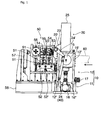
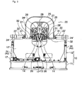
- a squeeze roll stand of the present embodiment is, as shown in Figs. 1 to 4 , installed particularly at a joint position of an electric resistance welded pipe manufacturing line, to joint a facing edge portion of an open pipe 60 passing through a forming roller group (not shown) and coming in with the facing edge portion facing upward.
- This squeeze roll stand includes a fixed portion 10 installed at the joint position of the manufacturing line, an inclination type movable portion 20 overlying the fixed portion 10, a lock mechanism 30 for fixing the movable portion 20 onto the fixed portion 10, and a drive mechanism 40 for driving and inclining the movable portion 20, and is combined with a bead grinding device 50 installed on the line downstream side of the squeeze roll stand.
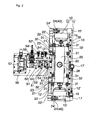
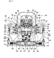
- the fixed portion 10 of the squeeze roll stand includes a base 11, and a stand main body 12 continuously provided on the base as shown in Figs. 5 and 6 .
- a lower roll 13 for supporting the open pipe 60 from the lower side, and left and right side rolls 14, 14 for pressing the open pipe 60 from both sides are provided.
- the lower roll 13 is a horizontal free roller rotatably supported by a bracket 13' on the lower side.
- the left and right side rolls 14, 14 are vertical rolls rotatably supported by cantilever type support bodies 14', 14' whose support sides are directed to the outer sides.
- the support bodies 14', 14' on both the sides are driven in the horizontal direction at right angle to the line by hydraulic servo control cylinders 15, 15 provided on both sides of the support bodies. Thereby, a pressing amount of the left and right side rolls 14, 14 is adjusted.
- the stand main body 12 includes cylinder cases 15', 15' of the hydraulic servo control cylinders 15, 15 on both the sides and detachable front and rear frame panels 12', 12'.
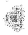
- An upper surface of the stand main body 12 is substantially entirely opened except front and rear edges and left and right edges (refer to Fig. 4 ).
- a pair of left and right first motors 16, 16 for driving and rotating the side rolls 14, 14 in the stand main body 12 is installed in the base 11 of the fixed portion 10.
- a second motor 17 for driving, elevating, and lowering the lower roll 13 in the stand main body 12 is mounted on the base 11 of the fixed portion 10.
- the first motors 16, 16 are arranged on both side ends in the base 11 in such a manner that output shafts are directed to the inner side. Since rotations of each output shaft are respectively transmitted to the side rolls 14, 14 on the upper side via gear boxes 16', 16' arranged on the respective inner sides, a pair of left and right drive shafts 16", 16" vertically arranged in the stand main body 12, and a pair of left and right insertion type couplings 18, 18 attached on the upper side of those members, the side rolls 14, 14 are driven and rotated in synchronization.
- the left and right insertion type couplings 18, 18 here are secured to upper ends of the drive shafts 16", 16" , and by inserting coupling pins protruding downward from lower ends of the side rolls 14, 14, couple the side rolls 14, 14 detachably.
- the insertion type couplings 18, 18 are movably supported in the lateral direction by horizontal guides 18', 18' at right angle to the line, and guided to arbitrary lateral positions by motor type jacks 18", 18".
- the drive shafts 16", 16" include universal joints for allowing lateral movement of the insertion type couplings 18, 18, that is, a change in the pressing amount of the side rolls 14, 14.
- the second motor 17 is mounted on a side edge on the front surface side (line upstream side) of the base 11 in such a manner that an output shaft is directed to the inner side.
- the output shaft of the second motor 17 adjusts height of the lower roll 13 by driving, elevating, and lowering, via a gear box 17' mounted on a center part on the front surface side (line upstream side) of the base 11, the gear box for changing the direction, and a jack 17" arranged in the stand main body 12, the bracket 13' on the upper side of the gear box and the jack.
- the movable portion 20 on the fixed portion 10 includes, as shown in Figs. 5 to 7 , an arch shape frame 25 having a reversed U shape when seen in a front view, and a pair of left and right upper rolls 26, 26 elevatably and lowerably supported in the frame 25.
- the inner side of the arch shape frame 25 is opened downward.
- the upper rolls 26, 26 are the same free rollers as the lower roll 13, arranged while being slightly inclined inward so as to press both edge portions of the open pipe 60 coming in with the facing edge portion facing upward from the obliquely upper side.
- the upper rolls 26, 26 are attached in a movable base 27 elevatably and lowerably provided in the frame 25.
- the movable base 27 is driven, elevated, and lowered by a hydraulic servo control cylinder 28 attached to a center part of the frame 25.
- a pair of left and right hydraulic servo control cylinders 29, 29 is attached downward to the movable base 27, and guides 26', 26' positioned on the lower side of the cylinders for guiding the upper rolls 26, 26 are provided.
- the hydraulic servo control cylinders 29, 29 and the guides 26', 26' are slightly inclined inward corresponding to inclination of the upper rolls 26, 26.
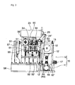
- the movable portion 20 is also formed to be pivoted by about 90 degrees toward the back surface side (line downstream side) of the fixed portion 10 taking an upper end of the back surface side (line downstream side) of the fixed portion 10 as a center.
- the movable portion 20 has a pair of left and right first brackets 21, 21 secured to an upper end on the back surface side (line downstream side) of the fixed portion 10, a pair of left and right rotation shafts 22, 22 horizontally supported by the first brackets 21, 21, and a pair of left and right second brackets 23, 23 secured to a lower end on the back surface side (line downstream side) of the pivoting portion 20.
- the left and right second brackets 23, 23 secured to the lower end on the back surface side (line downstream side) of the pivoting portion 20 are respectively arranged on each inner side of the left and right first brackets 21, 21, and secured to the rotation shafts 22, 22.
- Front ends of a pair of left and right levers 24', 24' secured to both ends of the rotation shafts 22, 22 are axially attached to rod front ends of actuators 24, 24 including a pair of left and right cylinders which is axially supported on both ends on the back surface side (line downstream side) of the base 11.
- the movable portion 20 When the movable portion 20 is at an assembling position on the fixed portion 10, rods of the actuators 24, 24 are retreated. By extending the rods of the actuators 24, 24 from this state, the movable portion 20 is inclined by about 90 degrees toward the back surface side (line downstream side) taking the horizontal rotation shafts 22, 22 on the back surface side (line downstream side) as a center, so as to be mounted on a bead grinding device 50 arranged on the back surface side (line downstream side) with a front surface facing upward.
- the actuators 24, 24 are the drive mechanism 40 for driving and inclining the movable portion 20.
- An upward facing state is a retreat position of the movable portion 20, in which the movable portion 20 is inclined by about 90 degrees toward the back surface side (line downstream side) and mounted on the bead grinding device 50 arranged on the back surface side (line downstream side) with the front surface facing upward.
- the reference numerals 22', 22' denote axial support parts for pivotably supporting the left and right rotation shafts 22, 22 on the inner sides of the levers 24', 24'.
- the lock mechanism 30 for fixing the movable portion 20 onto the fixed portion 10 includes a combination of a plurality of (herein, eight) clamps 31 provided on an upper surface of the fixed portion 10 as shown in Figs. 2 and 4 .
- Four of the eight clamps 31 are attached onto an upper surface of an edge (front edge) on the front surface side of the fixed portion 10 as two pairs of two clamps, and the remaining four clamps are attached onto an upper surface of an edge (rear edge) on the back surface side of the fixed portion 10 as two pairs of two clamps.
- the two pairs of clamps 31 attached onto the upper surface of the front edge are arranged on both sides of a center part, and the two clamps 31, 31 in each pair are arranged to face each other.
- the two pairs of clamps 31 attached onto the upper surface of the rear edge are arranged on both sides of a center part, and the two clamps 31, 31 in each pair are arranged to face each other.
- the four pairs of (eight) clamps 31 restraint plate shape stoppers 32, 32 on both sides protruding forward and rearward from both lower ends of the frame 25 in the movable portion 20 so as to fix onto the fixed portion 10 when the movable portion 20 is at the assembling position on the fixed portion 10.
- each end of the two plate shape stoppers 32, 32 protruding from both the lower ends of the frame 25 toward the upstream side, and ends of the two plate shape stoppers 32, 32 protruding toward the downstream side are engaged with an upper part of the front edge and an upper part of the rear edge of the fixed portion 10, so that the movable portion 20 is supported on the fixed portion 10.
- the movable portion 20 is supported and fixed onto the fixed portion 10.
- Each of the two plate shape stoppers 32, 32 on the front or rear side also serve as support members of the movable portion 20.
- the above eight clamps 31 are a hydraulic type here, and by making a clamp force by those clamps, that is, a force of fixing the plate shape stoppers 32, 32 on both the sides protruding forward and rearward onto the fixed portion 10 by the eight clamps 31, not less than a load generated in an engagement fixed part at the time of forming the pipe, backlash of the engagement fixed part is suppressed to minimum, so that the squeeze roll stand becomes highly rigid.
- height of the bead grinding device 50 continuously provided on the downstream side of the fixed portion 10 is limited so as to allow inclination of the movable portion 20 to the retreat position on the downstream side of the electric resistance welded pipe manufacturing line, and also to serve as a support body of the movable portion 20 on the lower side of the movable portion 20 inclined to the retreat position. Due to this height limitation, the bead grinding device 50 inherently adopts the following configuration.
- the bead grinding device 50 has a main frame 55 arranged on the downstream side of the fixed portion 10, a plurality of support rollers 51 provided in the main frame 55 so as to be spaced from each other in the line longitudinal direction for supporting a pipe shape material coming out from the squeeze roll stand, and a plurality of (herein, two) grinding blades 53 provided in the main frame 55 so as to be positioned on the upper side of the support rollers 51.
- the plurality of support rollers 51 are attached to an elevatable and lowerable common support frame 52, and their heights are collectively adjusted by driving, elevating, and lowering the support frame 52 with a motor jack 52' provided on the line side.
- the plurality of grinding blades 53 arranged together with the plurality of support rollers 51 so as to be spaced from each other in the line longitudinal direction are attached to individual elevation and lowering frames 54.
- the plurality of elevation and lowering frames 54 individually adjust height of the plurality of grinding blades 53.
- the plurality of elevation and lowering frames 54 for individually supporting the plurality of grinding blades 53 are respectively provided with position adjustment mechanisms for adjusting circumferential positions of the grinding blades 53.
- the height of the bead grinding device 50 is decreased to such a level that the movable portion 20 can be inclined by about 90 degrees toward the downstream side.
- a bead winder unit 56 is arranged so as to be positioned on the further downstream side of the plurality of grinding blades 53, and a support upper roll unit 57 is arranged on the further downstream side of the main frame 55.
- the support upper roll unit 57 is installed on a base 58 arranged on the downstream side of the squeeze roll stand together with the main frame 55.
- An upper part of the main frame 55 of the bead grinding device 50 is opened. Since the movable portion 20 does not overlie this upper part during operation, the part becomes in an opened state. As a result, a mode without fume retention that is also preferable in terms of a working environment is obtained.
- the movable portion 20 of the squeeze roll stand is fixed at the assembling position on the fixed portion 10 by the lock mechanism 30.
- the squeeze rolls in the squeeze roll stand that is, the lower roll 13 and the left and right side rolls 14, 14 in the fixed portion 10
- the pair of left and right upper rolls 26, 26 in the movable portion 20 exist at fixed positions.
- the pair of left and right first motors 16, 16 provided in the base 11 of the fixed portion 10 the left and right side rolls 14, 14 in the fixed portion 10 are driven and rotated.
- the height of the lower roll 31 in the fixed portion 10 is adjusted by the second motor 17 on the base 11, the pressing amount of the left and right side rolls 14, 14 is adjusted by the hydraulic servo control cylinders 15, 15, the lateral positions of the insertion type couplings 18, 18 are adjusted by the motor type jacks 18", 18", and the height of the upper rolls 26, 26 in the movable portion 20 is adjusted by the hydraulic servo control cylinder 28.
- the height of the plurality of support rollers 51 is adjusted by the motor jack 52', and the height of the plurality of grinding blades 53 is adjusted by the plurality of motor jacks 54'.
- the open pipe 60 comes into the squeeze roll stand with the facing edge portion facing upward, and the facing edge portion is jointed by heating with a heating device (not shown), pressing with the left and right side rolls 14, 14, and depressing with the left and right upper rolls 26, 26.
- the pipe shape material after finishing jointing successively comes into the bead grinding device 50 on the downstream side, and by stepwise removing an outer surface bead generated in joint parts by the plurality of grinding blades 53, becomes an electric resistance welded pipe with a circular section serving as a product.
- the clamp force by the eight clamps 31 in the lock mechanism 30 is set to not less than a forming load reaction force.
- the squeeze rolls in the squeeze roll stand are replaced.
- the eight clamps 31 in the lock mechanism 30 are actuated in the open direction.
- the plate shape stoppers 32, 32 on both the sides in the movable portion 20 the plate shape stoppers being bridged to the front edge and to the rear edge in the uppermost part of the fixed portion 10 are respectively released from the front edge and the rear edge.
- the movable portion 20 on the fixed portion 10 in the squeeze roll stand is inclined by about 90 degrees toward the back surface side (line downstream side) taking the rotation shaft 22 on the back surface side (line downstream side) as a fulcrum point, so as to overlie the bead grinding device 50 on the back surface side (line downstream side) with the front surface facing upward, the upper surface of the fixed portion 10 is opened.
- the inside of the arch shape frame 25 in the movable portion 20 is opened. Thereby, the left and right side rolls 14, 14 in the fixed portion 10 are simply replaced. In a case where replacement of the lower roll 13 is required, the replacement is also easily performed. Further, in a case where replacement of the left and right upper rolls 26, 26 in the movable portion 20 is required, the replacement is also easily performed.
- one or both of the front and rear frame panels 12', 12' can be detached. Thereby, a front surface and/or a rear surface of the fixed portion 10 are opened. Thus, the replacement of the squeeze rolls in the fixed portion 10 is furthermore easily performed.
- the movable portion 20 serving as an upper roll assembly can be inclined toward the line downstream side relatively to the fixed portion 10 below the movable portion, and the movable portion 20 is retreated from an upper part of the fixed portion 10 by an inclination operation thereof.
- a retreat operation is easy. Since the retreated movable portion 20 overlies the bead grinding device 50 on the line downstream side with the front surface facing upward, there is no need for a temporary installment space out of the line.
- the frame 55 of the bead grinding device 50 also serves as the support body of the movable portion 20, the configuration is simple. Further, the upper part of the fixed portion 10 after retreat of the movable portion 20 is in an opened state. Therefore, by setting a gate shape frame on the fixed portion 10, or the like, the roll replacement in the fixed portion 10 can be automatically performed. As a method of automatic roll replacement, various methods including use of a small hoist and use of various cylinders can be performed.
- the side rolls 14, 14 can be separated from the drive shafts 16", 16" only by bringing the side rolls up.
- the lateral positions of the insertion type couplings 18, 18 are adjusted by the motor type jacks 18", 18" in accordance with size of those rolls.
- the movable portion 20 in order to eliminate the movable portion 20 on the fixed portion 10 in the squeeze roll stand from the upper part of the fixed portion 10, the movable portion 20 is inclined toward the line downstream side taking a horizontal shaft (rotation shaft 22) at right angle to the line on the line downstream side as a fulcrum point.
- the movable portion can also be inclined toward the line upstream side taking a horizontal shaft at right angle to the line on the line upstream side as a fulcrum point, or the movable portion can also be inclined toward the line side taking a horizontal shaft parallel to the line on the line side as a fulcrum point.
- the movable portion can also be inclined in two steps taking two shafts of the horizontal shaft at right angle to the line on the line downstream side and the horizontal shaft parallel to the line on the line side as fulcrum points.
Landscapes
- Engineering & Computer Science (AREA)
- Mechanical Engineering (AREA)
- Bending Of Plates, Rods, And Pipes (AREA)
- Grinding And Polishing Of Tertiary Curved Surfaces And Surfaces With Complex Shapes (AREA)
- Tyre Moulding (AREA)
Applications Claiming Priority (2)
| Application Number | Priority Date | Filing Date | Title |
|---|---|---|---|
| JP2011091994A JP5781821B2 (ja) | 2011-04-18 | 2011-04-18 | スクイズロールスタンド |
| PCT/JP2011/067464 WO2012144090A1 (ja) | 2011-04-18 | 2011-07-29 | スクイズロールスタンド |
Publications (3)
| Publication Number | Publication Date |
|---|---|
| EP2700457A1 EP2700457A1 (en) | 2014-02-26 |
| EP2700457A4 EP2700457A4 (en) | 2014-12-31 |
| EP2700457B1 true EP2700457B1 (en) | 2015-11-04 |
Family
ID=47041232
Family Applications (1)
| Application Number | Title | Priority Date | Filing Date |
|---|---|---|---|
| EP11863940.0A Not-in-force EP2700457B1 (en) | 2011-04-18 | 2011-07-29 | Squeeze roll stand |
Country Status (5)
| Country | Link |
|---|---|
| US (1) | US9199290B2 (enExample) |
| EP (1) | EP2700457B1 (enExample) |
| JP (1) | JP5781821B2 (enExample) |
| RU (1) | RU2572931C2 (enExample) |
| WO (1) | WO2012144090A1 (enExample) |
Cited By (1)
| Publication number | Priority date | Publication date | Assignee | Title |
|---|---|---|---|---|
| WO2021206134A1 (ja) | 2020-04-09 | 2021-10-14 | 株式会社中田製作所 | 金属管の製造方法と装置 |
Families Citing this family (4)
| Publication number | Priority date | Publication date | Assignee | Title |
|---|---|---|---|---|
| JP2018134643A (ja) * | 2015-07-09 | 2018-08-30 | 株式会社中田製作所 | 管の成形方法及び装置 |
| CN107185997B (zh) * | 2017-07-05 | 2019-09-17 | 宁波钜智自动化装备有限公司 | 一种多轴伺服控制高精度erw焊管成形机构 |
| JP6823212B1 (ja) * | 2020-01-31 | 2021-01-27 | 株式会社中田製作所 | スクイズ装置 |
| CN121178649B (zh) * | 2025-11-24 | 2026-04-14 | 天津市友发德众钢管有限公司 | 大口径方矩管分体式高频挤压装置 |
Family Cites Families (17)
| Publication number | Priority date | Publication date | Assignee | Title |
|---|---|---|---|---|
| SU1092019A1 (ru) * | 1982-10-11 | 1984-05-15 | Предприятие П/Я Р-6930 | Устройство дл удалени сварочного грата |
| JPS60160927A (ja) | 1984-02-01 | 1985-08-22 | プリマハム株式会社 | 食品焼用フ−ド |
| JPS60160927U (ja) * | 1984-04-03 | 1985-10-25 | 新日本製鐵株式会社 | 造管設備における内張りロ−ル交換装置 |
| SU1590272A1 (ru) * | 1988-03-21 | 1990-09-07 | Институт Электросварки Им.Е.О.Патона | Устройство дл удалени кольцевого грата |
| GB2226513B (en) * | 1988-11-29 | 1992-04-08 | Senior Bigwood Limited | Tube weld mill |
| WO1991008064A1 (en) * | 1989-12-04 | 1991-06-13 | Kawasaki Steel Corporation | Apparatus for manufacturing welded steel pipe and method of operating thereof |
| US5192013A (en) * | 1991-09-20 | 1993-03-09 | Abbey Etna Machine Company | Scarfing apparatus |
| JPH0685715U (ja) | 1993-05-26 | 1994-12-13 | 住友金属工業株式会社 | 溶接管の外面ビード切削装置 |
| US5461896A (en) * | 1994-02-18 | 1995-10-31 | Abbey Etna Machine Company | Automated changeover tube mill |
| JP3053534B2 (ja) | 1994-09-30 | 2000-06-19 | 新日本製鐵株式会社 | スクイズロールスタンド |
| JP3394656B2 (ja) | 1996-08-26 | 2003-04-07 | 川崎製鉄株式会社 | 電縫鋼管の外面ビード切削装置 |
| JP2001150189A (ja) | 1999-11-24 | 2001-06-05 | Puropurai:Kk | 電縫管の外面ビード切屑の切断方法及び外面ビード切屑切断装置 |
| JP4250848B2 (ja) | 2000-02-17 | 2009-04-08 | Jfeスチール株式会社 | スクイズスタンドのトップロール取替装置 |
| JP4461549B2 (ja) | 2000-02-17 | 2010-05-12 | Jfeスチール株式会社 | ロールスタンドの吊装置及びロール替え方法 |
| DE10160004B4 (de) * | 2001-12-06 | 2004-01-29 | Sms Meer Gmbh | Verfahren und Vorrichtung zum Wechseln der Walzen in einem Rohr-Schweißgerüst |
| JP2006088215A (ja) | 2004-09-27 | 2006-04-06 | Jfe Steel Kk | 電縫管の外面ビード屑処理装置 |
| RU2392076C1 (ru) * | 2009-08-10 | 2010-06-20 | Открытое акционерное общество "Электростальский завод тяжелого машиностроения" | Трубосварочная клеть |
-
2011
- 2011-04-18 JP JP2011091994A patent/JP5781821B2/ja active Active
- 2011-07-29 US US14/112,814 patent/US9199290B2/en not_active Expired - Fee Related
- 2011-07-29 RU RU2013151069/02A patent/RU2572931C2/ru not_active IP Right Cessation
- 2011-07-29 WO PCT/JP2011/067464 patent/WO2012144090A1/ja not_active Ceased
- 2011-07-29 EP EP11863940.0A patent/EP2700457B1/en not_active Not-in-force
Cited By (1)
| Publication number | Priority date | Publication date | Assignee | Title |
|---|---|---|---|---|
| WO2021206134A1 (ja) | 2020-04-09 | 2021-10-14 | 株式会社中田製作所 | 金属管の製造方法と装置 |
Also Published As
| Publication number | Publication date |
|---|---|
| US9199290B2 (en) | 2015-12-01 |
| JP2012223782A (ja) | 2012-11-15 |
| EP2700457A1 (en) | 2014-02-26 |
| EP2700457A4 (en) | 2014-12-31 |
| JP5781821B2 (ja) | 2015-09-24 |
| RU2572931C2 (ru) | 2016-01-20 |
| WO2012144090A1 (ja) | 2012-10-26 |
| US20140130562A1 (en) | 2014-05-15 |
| RU2013151069A (ru) | 2015-05-27 |
Similar Documents
| Publication | Publication Date | Title |
|---|---|---|
| EP2700457B1 (en) | Squeeze roll stand | |
| US11219933B2 (en) | Apparatus and method for support and controlled advancement of a metal sheet in a bending machine for obtaining cylindrical or truncated cone structures | |
| CN117066903B (zh) | 用于不锈钢餐桌生产的自动化钢管切割装置 | |
| JP6233799B2 (ja) | ロータリースクリーン印刷装置 | |
| KR101270054B1 (ko) | 파이프 블랭킹 베벨러 | |
| JP6823212B1 (ja) | スクイズ装置 | |
| KR101519365B1 (ko) | 파이프 티 성형장치 및 이를 이용한 성형방법 | |
| CN115417224B (zh) | 一种智能板材纵剪分条系统 | |
| EP1873092A1 (en) | Bilateral machine for processing glass panes shaped like a parallelogram with non-right angles | |
| CN118253610A (zh) | 一种铝单板加工用卷板弯折装置 | |
| CN211386641U (zh) | 一种用于纵梁片料折弯的12米折弯机上下料工作台 | |
| KR101108565B1 (ko) | 자동 나이프 조립체 체인징 장치 | |
| KR102052030B1 (ko) | 파이프 밴딩머신 | |
| CN108340606B (zh) | 一种轮胎生产系统 | |
| CN111774510A (zh) | 一种盾构管片钢筋笼的弧形网片焊接系统 | |
| CN216888779U (zh) | 一种切边对中纠偏装置 | |
| KR200351907Y1 (ko) | 파이프 용접비드 제거장치 | |
| KR20120094621A (ko) | 링크 밴딩 시스템 | |
| CN110744217B (zh) | 可直接换型的隧道式焊机及其焊接方法 | |
| CN110561020B (zh) | 一种建筑塔机主肢自动焊接工作站 | |
| RU2450900C1 (ru) | Способ подготовки концов полос к контактной стыковой сварке | |
| WO2018116481A1 (ja) | バルジ加工用の金属管ベローズ成形方法、及び、その金属管ベローズ成形装置 | |
| CN118720513B (zh) | 一种飞行器起落架焊接装置及其方法 | |
| CN224173114U (zh) | 一种造纸机分切装置 | |
| US10160017B2 (en) | Torque balancing roll forming machine |
Legal Events
| Date | Code | Title | Description |
|---|---|---|---|
| PUAI | Public reference made under article 153(3) epc to a published international application that has entered the european phase |
Free format text: ORIGINAL CODE: 0009012 |
|
| 17P | Request for examination filed |
Effective date: 20131114 |
|
| AK | Designated contracting states |
Kind code of ref document: A1 Designated state(s): AL AT BE BG CH CY CZ DE DK EE ES FI FR GB GR HR HU IE IS IT LI LT LU LV MC MK MT NL NO PL PT RO RS SE SI SK SM TR |
|
| DAX | Request for extension of the european patent (deleted) | ||
| A4 | Supplementary search report drawn up and despatched |
Effective date: 20141203 |
|
| RIC1 | Information provided on ipc code assigned before grant |
Ipc: B21C 37/08 20060101ALI20141127BHEP Ipc: B21D 5/12 20060101AFI20141127BHEP |
|
| GRAP | Despatch of communication of intention to grant a patent |
Free format text: ORIGINAL CODE: EPIDOSNIGR1 |
|
| RIC1 | Information provided on ipc code assigned before grant |
Ipc: B21D 5/12 20060101AFI20150423BHEP Ipc: B21C 37/08 20060101ALI20150423BHEP |
|
| INTG | Intention to grant announced |
Effective date: 20150527 |
|
| GRAS | Grant fee paid |
Free format text: ORIGINAL CODE: EPIDOSNIGR3 |
|
| GRAA | (expected) grant |
Free format text: ORIGINAL CODE: 0009210 |
|
| AK | Designated contracting states |
Kind code of ref document: B1 Designated state(s): AL AT BE BG CH CY CZ DE DK EE ES FI FR GB GR HR HU IE IS IT LI LT LU LV MC MK MT NL NO PL PT RO RS SE SI SK SM TR |
|
| REG | Reference to a national code |
Ref country code: GB Ref legal event code: FG4D |
|
| REG | Reference to a national code |
Ref country code: CH Ref legal event code: EP |
|
| REG | Reference to a national code |
Ref country code: AT Ref legal event code: REF Ref document number: 758844 Country of ref document: AT Kind code of ref document: T Effective date: 20151115 |
|
| REG | Reference to a national code |
Ref country code: IE Ref legal event code: FG4D |
|
| REG | Reference to a national code |
Ref country code: DE Ref legal event code: R096 Ref document number: 602011021287 Country of ref document: DE |
|
| REG | Reference to a national code |
Ref country code: NL Ref legal event code: MP Effective date: 20151104 |
|
| REG | Reference to a national code |
Ref country code: LT Ref legal event code: MG4D |
|
| REG | Reference to a national code |
Ref country code: AT Ref legal event code: MK05 Ref document number: 758844 Country of ref document: AT Kind code of ref document: T Effective date: 20151104 |
|
| PG25 | Lapsed in a contracting state [announced via postgrant information from national office to epo] |
Ref country code: IS Free format text: LAPSE BECAUSE OF FAILURE TO SUBMIT A TRANSLATION OF THE DESCRIPTION OR TO PAY THE FEE WITHIN THE PRESCRIBED TIME-LIMIT Effective date: 20160304 Ref country code: NL Free format text: LAPSE BECAUSE OF FAILURE TO SUBMIT A TRANSLATION OF THE DESCRIPTION OR TO PAY THE FEE WITHIN THE PRESCRIBED TIME-LIMIT Effective date: 20151104 Ref country code: ES Free format text: LAPSE BECAUSE OF FAILURE TO SUBMIT A TRANSLATION OF THE DESCRIPTION OR TO PAY THE FEE WITHIN THE PRESCRIBED TIME-LIMIT Effective date: 20151104 Ref country code: HR Free format text: LAPSE BECAUSE OF FAILURE TO SUBMIT A TRANSLATION OF THE DESCRIPTION OR TO PAY THE FEE WITHIN THE PRESCRIBED TIME-LIMIT Effective date: 20151104 Ref country code: LT Free format text: LAPSE BECAUSE OF FAILURE TO SUBMIT A TRANSLATION OF THE DESCRIPTION OR TO PAY THE FEE WITHIN THE PRESCRIBED TIME-LIMIT Effective date: 20151104 Ref country code: NO Free format text: LAPSE BECAUSE OF FAILURE TO SUBMIT A TRANSLATION OF THE DESCRIPTION OR TO PAY THE FEE WITHIN THE PRESCRIBED TIME-LIMIT Effective date: 20160204 |
|
| PG25 | Lapsed in a contracting state [announced via postgrant information from national office to epo] |
Ref country code: GR Free format text: LAPSE BECAUSE OF FAILURE TO SUBMIT A TRANSLATION OF THE DESCRIPTION OR TO PAY THE FEE WITHIN THE PRESCRIBED TIME-LIMIT Effective date: 20160205 Ref country code: PT Free format text: LAPSE BECAUSE OF FAILURE TO SUBMIT A TRANSLATION OF THE DESCRIPTION OR TO PAY THE FEE WITHIN THE PRESCRIBED TIME-LIMIT Effective date: 20160304 Ref country code: AT Free format text: LAPSE BECAUSE OF FAILURE TO SUBMIT A TRANSLATION OF THE DESCRIPTION OR TO PAY THE FEE WITHIN THE PRESCRIBED TIME-LIMIT Effective date: 20151104 Ref country code: RS Free format text: LAPSE BECAUSE OF FAILURE TO SUBMIT A TRANSLATION OF THE DESCRIPTION OR TO PAY THE FEE WITHIN THE PRESCRIBED TIME-LIMIT Effective date: 20151104 Ref country code: PL Free format text: LAPSE BECAUSE OF FAILURE TO SUBMIT A TRANSLATION OF THE DESCRIPTION OR TO PAY THE FEE WITHIN THE PRESCRIBED TIME-LIMIT Effective date: 20151104 Ref country code: FI Free format text: LAPSE BECAUSE OF FAILURE TO SUBMIT A TRANSLATION OF THE DESCRIPTION OR TO PAY THE FEE WITHIN THE PRESCRIBED TIME-LIMIT Effective date: 20151104 Ref country code: SE Free format text: LAPSE BECAUSE OF FAILURE TO SUBMIT A TRANSLATION OF THE DESCRIPTION OR TO PAY THE FEE WITHIN THE PRESCRIBED TIME-LIMIT Effective date: 20151104 Ref country code: LV Free format text: LAPSE BECAUSE OF FAILURE TO SUBMIT A TRANSLATION OF THE DESCRIPTION OR TO PAY THE FEE WITHIN THE PRESCRIBED TIME-LIMIT Effective date: 20151104 |
|
| PG25 | Lapsed in a contracting state [announced via postgrant information from national office to epo] |
Ref country code: CZ Free format text: LAPSE BECAUSE OF FAILURE TO SUBMIT A TRANSLATION OF THE DESCRIPTION OR TO PAY THE FEE WITHIN THE PRESCRIBED TIME-LIMIT Effective date: 20151104 |
|
| REG | Reference to a national code |
Ref country code: DE Ref legal event code: R097 Ref document number: 602011021287 Country of ref document: DE |
|
| PG25 | Lapsed in a contracting state [announced via postgrant information from national office to epo] |
Ref country code: RO Free format text: LAPSE BECAUSE OF FAILURE TO SUBMIT A TRANSLATION OF THE DESCRIPTION OR TO PAY THE FEE WITHIN THE PRESCRIBED TIME-LIMIT Effective date: 20151104 Ref country code: EE Free format text: LAPSE BECAUSE OF FAILURE TO SUBMIT A TRANSLATION OF THE DESCRIPTION OR TO PAY THE FEE WITHIN THE PRESCRIBED TIME-LIMIT Effective date: 20151104 Ref country code: SK Free format text: LAPSE BECAUSE OF FAILURE TO SUBMIT A TRANSLATION OF THE DESCRIPTION OR TO PAY THE FEE WITHIN THE PRESCRIBED TIME-LIMIT Effective date: 20151104 Ref country code: SM Free format text: LAPSE BECAUSE OF FAILURE TO SUBMIT A TRANSLATION OF THE DESCRIPTION OR TO PAY THE FEE WITHIN THE PRESCRIBED TIME-LIMIT Effective date: 20151104 Ref country code: DK Free format text: LAPSE BECAUSE OF FAILURE TO SUBMIT A TRANSLATION OF THE DESCRIPTION OR TO PAY THE FEE WITHIN THE PRESCRIBED TIME-LIMIT Effective date: 20151104 |
|
| PLBE | No opposition filed within time limit |
Free format text: ORIGINAL CODE: 0009261 |
|
| STAA | Information on the status of an ep patent application or granted ep patent |
Free format text: STATUS: NO OPPOSITION FILED WITHIN TIME LIMIT |
|
| 26N | No opposition filed |
Effective date: 20160805 |
|
| PG25 | Lapsed in a contracting state [announced via postgrant information from national office to epo] |
Ref country code: SI Free format text: LAPSE BECAUSE OF FAILURE TO SUBMIT A TRANSLATION OF THE DESCRIPTION OR TO PAY THE FEE WITHIN THE PRESCRIBED TIME-LIMIT Effective date: 20151104 |
|
| PG25 | Lapsed in a contracting state [announced via postgrant information from national office to epo] |
Ref country code: BE Free format text: LAPSE BECAUSE OF FAILURE TO SUBMIT A TRANSLATION OF THE DESCRIPTION OR TO PAY THE FEE WITHIN THE PRESCRIBED TIME-LIMIT Effective date: 20151104 |
|
| REG | Reference to a national code |
Ref country code: CH Ref legal event code: PL |
|
| GBPC | Gb: european patent ceased through non-payment of renewal fee |
Effective date: 20160729 |
|
| PG25 | Lapsed in a contracting state [announced via postgrant information from national office to epo] |
Ref country code: MC Free format text: LAPSE BECAUSE OF FAILURE TO SUBMIT A TRANSLATION OF THE DESCRIPTION OR TO PAY THE FEE WITHIN THE PRESCRIBED TIME-LIMIT Effective date: 20151104 |
|
| PG25 | Lapsed in a contracting state [announced via postgrant information from national office to epo] |
Ref country code: LI Free format text: LAPSE BECAUSE OF NON-PAYMENT OF DUE FEES Effective date: 20160731 Ref country code: CH Free format text: LAPSE BECAUSE OF NON-PAYMENT OF DUE FEES Effective date: 20160731 Ref country code: FR Free format text: LAPSE BECAUSE OF NON-PAYMENT OF DUE FEES Effective date: 20160801 |
|
| REG | Reference to a national code |
Ref country code: FR Ref legal event code: ST Effective date: 20170331 |
|
| REG | Reference to a national code |
Ref country code: IE Ref legal event code: MM4A |
|
| PG25 | Lapsed in a contracting state [announced via postgrant information from national office to epo] |
Ref country code: GB Free format text: LAPSE BECAUSE OF NON-PAYMENT OF DUE FEES Effective date: 20160729 |
|
| PG25 | Lapsed in a contracting state [announced via postgrant information from national office to epo] |
Ref country code: IE Free format text: LAPSE BECAUSE OF NON-PAYMENT OF DUE FEES Effective date: 20160729 |
|
| PG25 | Lapsed in a contracting state [announced via postgrant information from national office to epo] |
Ref country code: LU Free format text: LAPSE BECAUSE OF NON-PAYMENT OF DUE FEES Effective date: 20160729 |
|
| PG25 | Lapsed in a contracting state [announced via postgrant information from national office to epo] |
Ref country code: CY Free format text: LAPSE BECAUSE OF FAILURE TO SUBMIT A TRANSLATION OF THE DESCRIPTION OR TO PAY THE FEE WITHIN THE PRESCRIBED TIME-LIMIT Effective date: 20151104 Ref country code: HU Free format text: LAPSE BECAUSE OF FAILURE TO SUBMIT A TRANSLATION OF THE DESCRIPTION OR TO PAY THE FEE WITHIN THE PRESCRIBED TIME-LIMIT; INVALID AB INITIO Effective date: 20110729 |
|
| PG25 | Lapsed in a contracting state [announced via postgrant information from national office to epo] |
Ref country code: MK Free format text: LAPSE BECAUSE OF FAILURE TO SUBMIT A TRANSLATION OF THE DESCRIPTION OR TO PAY THE FEE WITHIN THE PRESCRIBED TIME-LIMIT Effective date: 20151104 Ref country code: TR Free format text: LAPSE BECAUSE OF FAILURE TO SUBMIT A TRANSLATION OF THE DESCRIPTION OR TO PAY THE FEE WITHIN THE PRESCRIBED TIME-LIMIT Effective date: 20151104 Ref country code: MT Free format text: LAPSE BECAUSE OF NON-PAYMENT OF DUE FEES Effective date: 20160731 |
|
| PG25 | Lapsed in a contracting state [announced via postgrant information from national office to epo] |
Ref country code: BG Free format text: LAPSE BECAUSE OF FAILURE TO SUBMIT A TRANSLATION OF THE DESCRIPTION OR TO PAY THE FEE WITHIN THE PRESCRIBED TIME-LIMIT Effective date: 20151104 |
|
| PG25 | Lapsed in a contracting state [announced via postgrant information from national office to epo] |
Ref country code: AL Free format text: LAPSE BECAUSE OF FAILURE TO SUBMIT A TRANSLATION OF THE DESCRIPTION OR TO PAY THE FEE WITHIN THE PRESCRIBED TIME-LIMIT Effective date: 20151104 |
|
| PGFP | Annual fee paid to national office [announced via postgrant information from national office to epo] |
Ref country code: IT Payment date: 20190723 Year of fee payment: 9 Ref country code: DE Payment date: 20190731 Year of fee payment: 9 |
|
| REG | Reference to a national code |
Ref country code: DE Ref legal event code: R119 Ref document number: 602011021287 Country of ref document: DE |
|
| PG25 | Lapsed in a contracting state [announced via postgrant information from national office to epo] |
Ref country code: DE Free format text: LAPSE BECAUSE OF NON-PAYMENT OF DUE FEES Effective date: 20210202 |
|
| PG25 | Lapsed in a contracting state [announced via postgrant information from national office to epo] |
Ref country code: IT Free format text: LAPSE BECAUSE OF NON-PAYMENT OF DUE FEES Effective date: 20200729 |