EP2698591A1 - Heat flow switch - Google Patents
Heat flow switch Download PDFInfo
- Publication number
- EP2698591A1 EP2698591A1 EP12771928.4A EP12771928A EP2698591A1 EP 2698591 A1 EP2698591 A1 EP 2698591A1 EP 12771928 A EP12771928 A EP 12771928A EP 2698591 A1 EP2698591 A1 EP 2698591A1
- Authority
- EP
- European Patent Office
- Prior art keywords
- thermally conductive
- carbon nanotube
- float switch
- nanotube layer
- heat
- Prior art date
- Legal status (The legal status is an assumption and is not a legal conclusion. Google has not performed a legal analysis and makes no representation as to the accuracy of the status listed.)
- Withdrawn
Links
Images




Classifications
-
- H—ELECTRICITY
- H01—ELECTRIC ELEMENTS
- H01H—ELECTRIC SWITCHES; RELAYS; SELECTORS; EMERGENCY PROTECTIVE DEVICES
- H01H61/00—Electrothermal relays
- H01H61/01—Details
-
- B—PERFORMING OPERATIONS; TRANSPORTING
- B82—NANOTECHNOLOGY
- B82Y—SPECIFIC USES OR APPLICATIONS OF NANOSTRUCTURES; MEASUREMENT OR ANALYSIS OF NANOSTRUCTURES; MANUFACTURE OR TREATMENT OF NANOSTRUCTURES
- B82Y30/00—Nanotechnology for materials or surface science, e.g. nanocomposites
-
- F—MECHANICAL ENGINEERING; LIGHTING; HEATING; WEAPONS; BLASTING
- F28—HEAT EXCHANGE IN GENERAL
- F28F—DETAILS OF HEAT-EXCHANGE AND HEAT-TRANSFER APPARATUS, OF GENERAL APPLICATION
- F28F13/00—Arrangements for modifying heat-transfer, e.g. increasing, decreasing
-
- B—PERFORMING OPERATIONS; TRANSPORTING
- B82—NANOTECHNOLOGY
- B82Y—SPECIFIC USES OR APPLICATIONS OF NANOSTRUCTURES; MEASUREMENT OR ANALYSIS OF NANOSTRUCTURES; MANUFACTURE OR TREATMENT OF NANOSTRUCTURES
- B82Y99/00—Subject matter not provided for in other groups of this subclass
-
- F—MECHANICAL ENGINEERING; LIGHTING; HEATING; WEAPONS; BLASTING
- F28—HEAT EXCHANGE IN GENERAL
- F28F—DETAILS OF HEAT-EXCHANGE AND HEAT-TRANSFER APPARATUS, OF GENERAL APPLICATION
- F28F13/00—Arrangements for modifying heat-transfer, e.g. increasing, decreasing
- F28F2013/005—Thermal joints
- F28F2013/008—Variable conductance materials; Thermal switches
-
- F—MECHANICAL ENGINEERING; LIGHTING; HEATING; WEAPONS; BLASTING
- F28—HEAT EXCHANGE IN GENERAL
- F28F—DETAILS OF HEAT-EXCHANGE AND HEAT-TRANSFER APPARATUS, OF GENERAL APPLICATION
- F28F2255/00—Heat exchanger elements made of materials having special features or resulting from particular manufacturing processes
- F28F2255/20—Heat exchanger elements made of materials having special features or resulting from particular manufacturing processes with nanostructures
-
- Y—GENERAL TAGGING OF NEW TECHNOLOGICAL DEVELOPMENTS; GENERAL TAGGING OF CROSS-SECTIONAL TECHNOLOGIES SPANNING OVER SEVERAL SECTIONS OF THE IPC; TECHNICAL SUBJECTS COVERED BY FORMER USPC CROSS-REFERENCE ART COLLECTIONS [XRACs] AND DIGESTS
- Y10—TECHNICAL SUBJECTS COVERED BY FORMER USPC
- Y10S—TECHNICAL SUBJECTS COVERED BY FORMER USPC CROSS-REFERENCE ART COLLECTIONS [XRACs] AND DIGESTS
- Y10S977/00—Nanotechnology
- Y10S977/70—Nanostructure
- Y10S977/734—Fullerenes, i.e. graphene-based structures, such as nanohorns, nanococoons, nanoscrolls or fullerene-like structures, e.g. WS2 or MoS2 chalcogenide nanotubes, planar C3N4, etc.
- Y10S977/742—Carbon nanotubes, CNTs
-
- Y—GENERAL TAGGING OF NEW TECHNOLOGICAL DEVELOPMENTS; GENERAL TAGGING OF CROSS-SECTIONAL TECHNOLOGIES SPANNING OVER SEVERAL SECTIONS OF THE IPC; TECHNICAL SUBJECTS COVERED BY FORMER USPC CROSS-REFERENCE ART COLLECTIONS [XRACs] AND DIGESTS
- Y10—TECHNICAL SUBJECTS COVERED BY FORMER USPC
- Y10S—TECHNICAL SUBJECTS COVERED BY FORMER USPC CROSS-REFERENCE ART COLLECTIONS [XRACs] AND DIGESTS
- Y10S977/00—Nanotechnology
- Y10S977/902—Specified use of nanostructure
- Y10S977/932—Specified use of nanostructure for electronic or optoelectronic application
Definitions
- the technique disclosed in the present description relates to a heat float switch capable of changing thermal conductivity by switching states between a state in which two members are in contact with each other and a state in which the members are not in contact with each other.
- Japanese National Publication of PCT Application No. 2009-531821 discloses a heat float switch that changes states between a state in which two members are in contact with each other and a state in which the members are not in contact with each other. In the state in which two members are in contact with each other (hereinafter referred to as a connected state), heat is transferred between these members. In the state in which two members are not in contact with each other, heat transfer between these members is blocked.
- the thermal resistance between the two members in the connected state is low (hereinafter, the thermal resistance between the two members in the connected state will be referred to the thermal resistance of the heat float switch).
- the thermal resistance between the two members in the connected state will be referred to the thermal resistance of the heat float switch.
- the thermal resistance between the two members in the connected state will be referred to the thermal resistance of the heat float switch.
- the thermal resistance between the two members in the connected state will be referred to the thermal resistance of the heat float switch.
- the thermal resistance between the two members in the connected state will be referred to the thermal resistance of the heat float switch.
- a heat float switch disclosed in the present description includes a first member and a second member.
- the first member includes a base member and a carbon nanotube layer formed on the surface of the base member.
- the heat float switch is configured to switch states between a connected state in which the carbon nanotube layer of the first member is in contact with the second member and an unconnected state in which the carbon nanotube layer of the first member is not in contact with the second member.
- the switching between the connected state and the unconnected state may be performed electrically or may be performed by another method.
- the connected state and the unconnected state may be switched by an actuator that is electrically controlled to move at least one of the first and second members.
- the connected state and the unconnected state may be switched by using thermal expansion and contraction of the first and second members.
- the first member includes the carbon nanotube layer.
- Carbon nanotubes have a very high thermal conductivity.
- the carbon nanotubes have high elasticity.
- the carbon nanotube layer can be deformed elastically. Therefore, even when very small uneven depressions are present on a contacting surface of the second member (a surface that contacts the carbon nanotube layer in the connected state), the carbon nanotube layer can be deformed to match the uneven depressions on the second member when the carbon nanotube layer makes contact with the second member.
- gaps are rarely formed in the interface between the first and second members being in the connected state. That is, the carbon nanotube layer can be in close contact with the contacting surface of the second member. In this manner, in this heat float switch, the carbon nanotube layer having very high thermal conductivity is in close-contact with the second member.
- the heat float switch has low thermal resistance (the thermal resistance between the first and second members in the connected state).
- Japanese Patent Application Publication No. 2009-253123 discloses a technique of connecting a semiconductor device and a heat sink by a carbon nanotube layer in order to reduce the thermal resistance between the semiconductor device and the heat sink.
- this technique is different from the technique of the present description relating to a heat float switch that switches states between the connected state and the unconnected state, in that the heat sink is fixed to the semiconductor device (that is, both are always in the connected state).
- the heat float switch disclosed in the present description since the switching between the connected state and the unconnected state is repeated, pressure is repeatedly applied to the carbon nanotube layer. That is, the technique disclosed in the present description provides a finding that carbon nanotubes have practical durability against repeated application of pressure and realizes a heat float switch having durability of a practical level and low thermal resistance by utilizing the durability.
- the second member includes a base member and a carbon nanotube layer formed on the surface of the base member, and the carbon nanotube layer of the first member is in contact with the carbon nanotube layer of the second member in the connected state.
- the carbon nanotube layer is also formed on the contacting surface of the second member, the carbon nanotube layers of both the first and second members in the connected state can be deformed elastically.
- the first member can come into closer contact with the second member. Therefore, according to this configuration, it is possible to further reduce the thermal resistance of the heat float switch.
- the heat float switch it is preferable that 30% or more of carbon nanotubes included in the carbon nanotube layer of the first member stand so as to have an angle of 60 degrees or more with respect to the base member.
- the angle of 0 degree means that the carbon nanotubes are parallel to the surface of the base member, and the angle of 90 degrees means that the carbon nanotubes are vertical to the surface of the base member.
- a resin is impregnated in the carbon nanotube layer of the first member.
- the thickness of the carbon nanotube layer of the first member is 0.5 ⁇ m or more.
- the carbon nanotube layer has a thickness of 0.5 ⁇ m or more, the carbon nanotube layer can be appropriately deformed to match the shape of the contacting surface of the second member.
- the base member of the first member is made of SiC.
- the connection strength between the carbon nanotubes and the base member is likely to increase.
- the base member made of SiC it is preferable to form the carbon nanotube layer on the surface of the base member by heating the base member made of SiC in a reduced-pressure atmosphere and oxidizing and removing Si atoms on the surface of the base member.
- the carbon nanotube layer is formed in this manner, it is possible to further improve the connection strength between the carbon nanotube and the base member.
- a heat float switch 10 includes a thermally conductive member 20, a thermally conductive member 30, a guide 40, and an actuator 50.
- the thermally conductive member 20 includes a contacting surface 20a.
- the thermally conductive member 30 includes a contacting surface 30a.
- the thermally conductive members 20 and 30 are disposed at such positions that the contacting surfaces 20a and 30a face each other.
- the thermally conductive member 20 is fixed to the guide 40.
- the thermally conductive member 30 is restricted by the guide 40 so as to be immovable in a lateral direction (a direction parallel to the contacting surface 20a) in relation to the thermally conductive member 20.
- the thermally conductive member 30 is guided by the guide 40 so as to move closer to or away from the thermally conductive member 20.
- the actuator 50 is connected to the thermally conductive member 30 to allow the thermally conductive member 30 to move closer to or away from the thermally conductive member 20.
- states are switched between a state in which the thermally conductive member 20 is not in contact with the thermally conductive member 30 as shown in FIG. 1 (hereinafter referred to as an unconnected state) and a state in which the thermally conductive member 20 is in contact with the thermally conductive member 30 (hereinafter referred to as a connected state).
- the operation of the actuator 50 is electrically controlled by a control circuit (not shown).
- the guide 40 is made of a heat insulating material.
- the thermally conductive member 20 is made mainly of SiC and the thermal conductivity of the thermally conductive member 20 is high, which will be described in detail later.
- the thermally conductive member 30 is made of Cu and the thermal conductivity of the thermally conductive member 30 is high.
- the thermally conductive member 20 is connected to a high-temperature member (not shown), and the thermally conductive member 30 is connected to a low-temperature member (not shown).
- heat transfer can be controlled by the heat float switch 10.
- FIG. 3 shows an enlarged side view of a portion of the heat float switch 10 near the contacting surfaces 20a and 30a.
- the thermally conductive member 20 includes a base member 22 and a carbon nanotube layer 24.
- the base member 22 is made of SiC.
- a number of carbon nanotubes 26 stand on a surface 22a of the base member 22 closer to the thermally conductive member 30. These carbon nanotubes 26 form the carbon nanotube layer 24. The distal ends of the carbon nanotubes 26 form the contacting surface 20a.
- uneven depressions are formed on the contacting surface 30a of the thermally conductive member 30. These uneven depressions have a depth of nanometer order and cannot be removed even after the contacting surface 30a is subjected to flattening processing.
- the carbon nanotube layer 24 of the thermally conductive member 20 makes contact with the contacting surface 30a of the thermally conductive member 30.
- the distal ends of the carbon nanotubes 26 make contact with the contacting surface 30a.
- the carbon nanotubes 26 are pressed in the axial direction (the longitudinal direction) with the distal ends making contact with the contacting surface 30a. In this way, the carbon nanotubes 26 are warped.
- the whole carbon nanotube layer 24 is elastically deformed to match the uneven depression shape of the contacting surface 30a.
- FIG. 5 shows an enlarged side view near contacting surfaces of a conventional heat float switch.
- a carbon nanotube layer is not formed on any one of the contacting surfaces 320a and 330a.
- nanometer-order uneven depressions are present on the contacting surfaces 320a and 330a.
- gaps 350 are formed in the interface between thermally conductive members 320 and 330 in the connected state.
- the carbon nanotube layer 24 is in close contact with the contacting surface 30a.
- the carbon nanotubes 26 have high thermal conductivity.
- the carbon nanotubes 26 have very high thermal conductivity (approximately 3000 W/mK) in the longitudinal direction.
- the base member 22 is made of SiC, the thermal conductivity of the base member 22 is also high (approximately 150 W/mK).
- the carbon nanotubes 26 stand on the base member 22 made of SiC.
- the thermal conductivity of a connecting portion between the carbon nanotubes 26 and the base member 22 (the boundary between the carbon nanotube layer 24 and the base member 22) is also high.
- the thermal resistance between the thermally conductive members 20 and 30 in the connected state is low. That is, the heat float switch 10 according to the first embodiment has lower thermal resistance than the conventional heat float switch.
- the carbon nanotube layer 24 is easily deformed.
- the carbon nanotube layer 24 can come into close contact with the thermally conductive member 30. That is, in the heat float switch 10, low thermal resistance is obtained with small pressing force.
- the actuator 50 having small pressing ability can be used. Due to this, it is possible to decrease the size of the heat float switch 10.
- the heat float switch 10 repeatedly switches the states between the connected state and the unconnected state.
- the carbon nanotubes 26 are repeatedly pressed by the thermally conductive member 30.
- the carbon nanotubes 26 have high durability against the repeated application of pressure.
- the heat float switch 10 according to the first embodiment has sufficient durability.
- the carbon nanotubes 26 are formed by heating the base member 22 made of SiC to 1400°C or more (for example, 1600°C) in a reduced-pressure atmosphere.
- SiC on the surface of the base member 22 is decomposed according to a reaction formula: SiC (solid) + O (gas) ⁇ SiO (gas) + C (solid). That is, Si atoms in SiC crystals are selectively oxidized and removed, and C atoms remaining on the surface self-assemble carbon nanotubes.
- the carbon nanotubes 26 grow approximately vertical to the base member 22 made of SiC.
- the carbon nanotubes 26 are grown according to this method, it is expected that covalent bonding are maintained in the connecting portion between the carbon nanotubes 26 and SiC.
- high strength is obtained in the connecting portion between the carbon nanotubes 26 and the base member 22, and high thermal conductivity is obtained in the connecting portion.
- the carbon nanotubes 26 have higher durability against repeated application of pressure. Due to this, the durability of the heat float switch 10 according to the first embodiment is further improved.
- FIG. 6 shows a state in which a very small extraneous material 360 is caught between the two thermally conductive members 320 and 330 of the conventional heat float switch.
- the thermally conductive members 320 and 330 cannot make whole-surface contact with each other, and the thermal resistance of the heat float switch increases remarkably.
- the heat float switch 10 according to the first embodiment as shown in FIG.
- a resin may be impregnated in the carbon nanotube layer 24.
- the resin When a resin is impregnated in the carbon nanotube layer 24, the resin enters into the space between the carbon nanotubes 26. Due to this, it is possible to further increase the thermal conductivity of the carbon nanotube layer 24.
- the resin being impregnated is preferably as soft as not to prevent the deformation of the carbon nanotubes 26, and a gelled resin (for example, gelled thermally conductive grease) is preferred.
- a heat float switch 110 according to a second embodiment has the same configuration as the heat float switch 10 according to the first embodiment except for the thermally conductive member 30.
- the thermally conductive member 30 includes a base member 32 and a carbon nanotube layer 34.
- the base member 32 is made of SiC.
- a number of carbon nanotubes 36 stand on a surface 32a of the base member 32 closer to the thermally conductive member 20. These carbon nanotubes 36 form the carbon nanotube layer 34.
- the distal ends of the carbon nanotubes 36 form a contacting surface 30a of the thermally conductive member 30.
- both the contacting surface 20a of the thermally conductive member 20 and the contacting surface 30a of the thermally conductive member 30 are formed by the carbon nanotube layer.
- both carbon nanotube layers 24 and 34 are elastically deformed.
- gaps are more rarely formed in the boundary between the thermally conductive members 20 and 30. Therefore, the heat float switch 110 has low thermal resistance.
- a resin may be impregnated in the carbon nanotube layers 24 and 34.
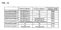
- FIG. 10 shows evaluation results obtained by simulating the thermal resistance (interface thermal resistance between thermally conductive members 1 and 2 shown in FIG. 10 ) of heat float switches having the configuration of the first and second embodiments.
- FIG. 10 also shows evaluation results of Comparative Examples 1 and 2 having the configuration of the conventional heat float switch.
- Comparative Example 1 a configuration in which both thermally conductive members were made of Cu (with no carbon nanotube layer) was evaluated.
- Comparative Example 2 a configuration in which silicon grease was coated on the contacting surfaces of the thermally conductive members of Comparative Example 1 was evaluated.
- the configurations of Experimental Examples 1 to 6 provide thermal resistance that is remarkably lower than that of any one of the configurations of Comparative Examples 1 and 2. It can be understood from the results of FIG. 10 that a sufficient thermal resistance reducing effect is obtained if the thickness of the carbon nanotube layer is 0.5 ⁇ m or more. In particular, it can be understood that the thermal resistance can be reduced more effectively if the thickness of the carbon nanotube layer is 1.0 ⁇ m or more.
- the surface of the thermally conductive members may be covered with an oxide film having high thermal resistance and the thermal resistance between the thermally conductive members may increase with time.
- the contacting surface of at least one of the thermally conductive members is made of a carbon nanotube layer, an oxide film is prevented from being formed on the contacting surface. Due to this, it is possible to suppress the thermal resistance between the thermally conductive members from increasing. Further, in the conventional heat float switch, since the thermally conductive member is metal, the contacting surface may be worn due to repeated use.
- the carbon nanotube layer that constitutes the contacting surface has high wear resistance, it is possible to suppress the occurrence of wear. Moreover, in the conventional heat float switch, since two thermally conductive members are connected with strong force to obtain low thermal resistance, the two thermally conductive members made of metal may adhere to each other. In the heat float switches according to the above mentioned embodiments, since low thermal resistance is obtained without using a great force, and no metal members are brought into contact with each other, the problem of adhesion can be prevented.
- FIGS. 11 and 12 show a heat float switch 210 having three thermally conductive members 220, 230, and 240.
- a contacting surface 220a of the thermally conductive member 220 is formed of a carbon nanotube layer 224, the thermal resistance between the thermally conductive members 220 and 230 in the connected state decreases.
- a contacting surface 240a of the thermally conductive member 240 is formed of a carbon nanotube layer 244, the thermal resistance between the thermally conductive members 240 and 230 in the connected state decreases.
- a carbon nanotube layer may be formed on a contacting surface closer to the thermally conductive member 230.
- the states are switched between the unconnected state and the connected state by moving one thermally conductive member in parallel to the other thermally conductive member.
- torsion, sideslip, or the like may be applied to one thermally conductive member so that shearing force occurs between the thermally conductive members.
- the thermally conductive members are connected in this manner, the carbon nanotube layer can more easily come in close-contact with a counterpart contacting surface and the thermal resistance can be decreased further.
- both thermally conductive members are formed of the carbon nanotube layer, since the carbon nanotubes of both thermally conductive members are connected so as to interdigitate with each other, it is possible to increase the contact area as a result. Therefore, it is possible to further decrease the thermal resistance.
- the heat float switch of which the states are switched between the connected state and the unconnected state by the actuator that is electrically controlled has been described.
- the technique of the present description may be also applied to a heat float switch of which the states are switched between the connected state and the unconnected state by thermal deformation of two thermally conductive members.
- the technique of the present description may be applied to a heat float switch in which two thermally conductive members are not in contact with each other when the temperature of the heat float switch is low, and if the temperature of at least one thermally conductive member increases, the thermally conductive member expands and then the two thermally conductive members come in contact with each other.
- an additional member that thermally expands may be provided separately from the thermally conductive member of the heat float switch so as to be connected to at least one thermally conductive member.
- a heat float switch it is possible to reduce the thermal resistance of the heat float switch by forming a carbon nanotube layer on any one or both of the contacting surfaces of two thermally conductive members.
- the thermal expansion coefficient of the thermally conductive members is high.
- the two thermally conductive members may have different thermal expansion coefficients and may have the same thermal expansion coefficient.
- the density of carbon nanotubes in the carbon nanotube layer is preferably 20% or more and 90% or smaller.
- the carbon nanotubes have distal ends that make contact with the counterpart thermally conductive member.
- the carbon nanotubes have very high thermal conductivity in the longitudinal direction, it is preferable that the carbon nanotubes have the distal ends that make contact with the counterpart thermally conductive member in such a manner.
- the carbon nanotubes stand at an angle as vertical as possible with respect to the base member, if the carbon nanotubes stand at an angle of 45 degrees or more with respect to the surface of the base member, the above effects can be obtained.
- This angle means the angle ⁇ 1 between the central axis C1 of a carbon nanotube and the surface S1 of the base member as shown in FIG. 13 .
- the angle can be measured by approximating the entire surface of the base member in a region where the carbon nanotubes stand to a flat surface.
- the base member is made of SiC
- the base member may be formed of another member.
- the length of the carbon nanotube is 4 ⁇ m or smaller when the carbon nanotubes are formed on the surface of the base member by heating SiC which is the base member in a reduced-pressure atmosphere to selectively oxidize and remove Si atoms. That is, the thickness of the carbon nanotube layer is preferably 4 ⁇ m or smaller.
Landscapes
- Engineering & Computer Science (AREA)
- Chemical & Material Sciences (AREA)
- Physics & Mathematics (AREA)
- Nanotechnology (AREA)
- Materials Engineering (AREA)
- General Physics & Mathematics (AREA)
- Condensed Matter Physics & Semiconductors (AREA)
- Crystallography & Structural Chemistry (AREA)
- Composite Materials (AREA)
- Thermal Sciences (AREA)
- Mechanical Engineering (AREA)
- General Engineering & Computer Science (AREA)
- Contacts (AREA)
- Carbon And Carbon Compounds (AREA)
Abstract
Description
- This application is based upon and claims the benefit of priority of the prior Japanese Patent application No.
2011-088535, filed on April 12, 2011 - The technique disclosed in the present description relates to a heat float switch capable of changing thermal conductivity by switching states between a state in which two members are in contact with each other and a state in which the members are not in contact with each other.
- Japanese National Publication of PCT Application No.
2009-531821 - In a heat float switch, it is preferable that the thermal resistance between the two members in the connected state is low (hereinafter, the thermal resistance between the two members in the connected state will be referred to the thermal resistance of the heat float switch). In order to decrease the thermal resistance of the heat float switch, it is necessary to form the contacting surfaces of the two members as flat as possible. This is because, when uneven depressions are present on the contacting surfaces, gaps are formed in the interface between the two members being in the connected state and the thermal resistance between these members increases. However, even when the contacting surfaces are processed to be flat, nanometer-order uneven depressions remain on the contacting surfaces. These uneven depressions become one of the causes that increase the thermal resistance of the heat float switch. Thus, it is desired to further reduce the thermal resistance of the heat float switch. Thus, the present description provides a heat float switch having lower thermal resistance.
- A heat float switch disclosed in the present description includes a first member and a second member. The first member includes a base member and a carbon nanotube layer formed on the surface of the base member. The heat float switch is configured to switch states between a connected state in which the carbon nanotube layer of the first member is in contact with the second member and an unconnected state in which the carbon nanotube layer of the first member is not in contact with the second member.
- The switching between the connected state and the unconnected state may be performed electrically or may be performed by another method. For example, the connected state and the unconnected state may be switched by an actuator that is electrically controlled to move at least one of the first and second members. Moreover, the connected state and the unconnected state may be switched by using thermal expansion and contraction of the first and second members.
- In the heat float switch, the first member includes the carbon nanotube layer. Carbon nanotubes have a very high thermal conductivity. Moreover, the carbon nanotubes have high elasticity. Thus, the carbon nanotube layer can be deformed elastically. Therefore, even when very small uneven depressions are present on a contacting surface of the second member (a surface that contacts the carbon nanotube layer in the connected state), the carbon nanotube layer can be deformed to match the uneven depressions on the second member when the carbon nanotube layer makes contact with the second member. Thus, in this heat float switch, gaps are rarely formed in the interface between the first and second members being in the connected state. That is, the carbon nanotube layer can be in close contact with the contacting surface of the second member. In this manner, in this heat float switch, the carbon nanotube layer having very high thermal conductivity is in close-contact with the second member. Thus, the heat float switch has low thermal resistance (the thermal resistance between the first and second members in the connected state).
- Japanese Patent Application Publication No.
2009-253123 - In the heat float switch, it is preferable that the second member includes a base member and a carbon nanotube layer formed on the surface of the base member, and the carbon nanotube layer of the first member is in contact with the carbon nanotube layer of the second member in the connected state.
- In this manner, if the carbon nanotube layer is also formed on the contacting surface of the second member, the carbon nanotube layers of both the first and second members in the connected state can be deformed elastically. Thus, the first member can come into closer contact with the second member. Therefore, according to this configuration, it is possible to further reduce the thermal resistance of the heat float switch.
- In the heat float switch, it is preferable that 30% or more of carbon nanotubes included in the carbon nanotube layer of the first member stand so as to have an angle of 60 degrees or more with respect to the base member. The angle of 0 degree means that the carbon nanotubes are parallel to the surface of the base member, and the angle of 90 degrees means that the carbon nanotubes are vertical to the surface of the base member.
- In this manner, when most of the carbon nanotubes included in the carbon nanotube layer of the first member stand at an angle close to 90 degrees with respect to the surface of the base member, most of the carbon nanotubes have distal ends being in contact with the second member. Thus, the carbon nanotube layer can easily come in close contact with the second member.
- In the heat float switch, it is preferable that a resin is impregnated in the carbon nanotube layer of the first member.
- In this manner, when a resin is impregnated in the gaps between the carbon nanotubes in the carbon nanotube layer, since the thermal conductivity of the carbon nanotube layer increases further, it is possible to further reduce the thermal resistance of the heat float switch.
- In the heat float switch, it is preferable that the thickness of the carbon nanotube layer of the first member is 0.5 µm or more.
- When the carbon nanotube layer has a thickness of 0.5 µm or more, the carbon nanotube layer can be appropriately deformed to match the shape of the contacting surface of the second member.
- In the heat float switch, it is preferable that the base member of the first member is made of SiC.
- When the base member made of SiC is used, the connection strength between the carbon nanotubes and the base member is likely to increase. Thus, according to this configuration, it is possible to improve the durability of the heat float switch. When the base member made of SiC is used, it is preferable to form the carbon nanotube layer on the surface of the base member by heating the base member made of SiC in a reduced-pressure atmosphere and oxidizing and removing Si atoms on the surface of the base member. When the carbon nanotube layer is formed in this manner, it is possible to further improve the connection strength between the carbon nanotube and the base member.
-
-
FIG. 1 is a side view of a heat float switch according to a first embodiment (unconnected state); -
FIG. 2 is a side view of the heat float switch according to the first embodiment (connected state); -
FIG. 3 is an enlarged side view near contacting surfaces of the heat float switch according to the first embodiment (unconnected state); -
FIG. 4 is an enlarged side view near the contacting surfaces of the heat float switch according to the first embodiment (connected state); -
FIG. 5 is an enlarged side view near contacting surfaces of a conventional heat float switch (connected state); -
FIG. 6 is an enlarged side view near the contacting surfaces of the conventional heat float switch when extraneous material is caught between the contacting surfaces; -
FIG. 7 is an enlarged side view near the contacting surfaces of the heat float switch according to the first embodiment when an extraneous material is caught between the contacting surfaces; -
FIG. 8 is an enlarged side view near contacting surfaces of a heat float switch according to a second embodiment (unconnected state); -
FIG. 9 is an enlarged side view near the contacting surfaces of the heat float switch according to the second embodiment (connected state); -
FIG. 10 is a table showing evaluation results of thermal resistance of heat float switches according to experimental examples; -
FIG. 11 is an enlarged side view near contacting surfaces of a heat float switch according to a modified embodiment (unconnected state); -
FIG. 12 is an enlarged side view near contacting surfaces of the heat float switch according to the modified embodiment (connected state); and -
FIG. 13 is a view for explaining a standing angle of a carbon nanotube. - As shown in
FIG. 1 , aheat float switch 10 according to a first embodiment includes a thermallyconductive member 20, a thermallyconductive member 30, aguide 40, and anactuator 50. The thermallyconductive member 20 includes a contactingsurface 20a. The thermallyconductive member 30 includes a contactingsurface 30a. The thermallyconductive members surfaces conductive member 20 is fixed to theguide 40. The thermallyconductive member 30 is restricted by theguide 40 so as to be immovable in a lateral direction (a direction parallel to the contactingsurface 20a) in relation to the thermallyconductive member 20. Moreover, the thermallyconductive member 30 is guided by theguide 40 so as to move closer to or away from the thermallyconductive member 20. Theactuator 50 is connected to the thermallyconductive member 30 to allow the thermallyconductive member 30 to move closer to or away from the thermallyconductive member 20. When theactuator 50 moves the thermallyconductive member 30, states are switched between a state in which the thermallyconductive member 20 is not in contact with the thermallyconductive member 30 as shown inFIG. 1 (hereinafter referred to as an unconnected state) and a state in which the thermallyconductive member 20 is in contact with the thermally conductive member 30 (hereinafter referred to as a connected state). The operation of theactuator 50 is electrically controlled by a control circuit (not shown). - The
guide 40 is made of a heat insulating material. The thermallyconductive member 20 is made mainly of SiC and the thermal conductivity of the thermallyconductive member 20 is high, which will be described in detail later. Moreover, the thermallyconductive member 30 is made of Cu and the thermal conductivity of the thermallyconductive member 30 is high. The thermallyconductive member 20 is connected to a high-temperature member (not shown), and the thermallyconductive member 30 is connected to a low-temperature member (not shown). Thus, heat is transferred from the thermallyconductive member 20 to the thermallyconductive member 30 in the connected state, whereas heat transfer from the thermallyconductive member 20 to the thermallyconductive member 30 is blocked in the unconnected state. That is, the heat transfer can be controlled by theheat float switch 10. -
FIG. 3 shows an enlarged side view of a portion of theheat float switch 10 near the contactingsurfaces FIG. 3 , the thermallyconductive member 20 includes abase member 22 and acarbon nanotube layer 24. Thebase member 22 is made of SiC. A number ofcarbon nanotubes 26 stand on asurface 22a of thebase member 22 closer to the thermallyconductive member 30. Thesecarbon nanotubes 26 form thecarbon nanotube layer 24. The distal ends of thecarbon nanotubes 26 form the contactingsurface 20a. - As shown in
FIG. 3 , uneven depressions are formed on the contactingsurface 30a of the thermallyconductive member 30. These uneven depressions have a depth of nanometer order and cannot be removed even after the contactingsurface 30a is subjected to flattening processing. - As shown in
FIG. 4 , when theheat float switch 10 is put into the connected state, thecarbon nanotube layer 24 of the thermallyconductive member 20 makes contact with the contactingsurface 30a of the thermallyconductive member 30. In this case, the distal ends of thecarbon nanotubes 26 make contact with the contactingsurface 30a. Thecarbon nanotubes 26 are pressed in the axial direction (the longitudinal direction) with the distal ends making contact with the contactingsurface 30a. In this way, thecarbon nanotubes 26 are warped. Thus, the wholecarbon nanotube layer 24 is elastically deformed to match the uneven depression shape of the contactingsurface 30a. - On the other hand,
FIG. 5 shows an enlarged side view near contacting surfaces of a conventional heat float switch. In the conventional heat float switch, a carbon nanotube layer is not formed on any one of the contactingsurfaces surfaces gaps 350 are formed in the interface between thermallyconductive members - As is obvious from comparison between
FIGS. 4 and5 , in theheat float switch 10 according to the first embodiment, gaps are rarely formed in the interface between the thermallyconductive members heat float switch 10, thecarbon nanotube layer 24 is in close contact with the contactingsurface 30a. Moreover, thecarbon nanotubes 26 have high thermal conductivity. In particular, thecarbon nanotubes 26 have very high thermal conductivity (approximately 3000 W/mK) in the longitudinal direction. Further, since thebase member 22 is made of SiC, the thermal conductivity of thebase member 22 is also high (approximately 150 W/mK). Furthermore, thecarbon nanotubes 26 stand on thebase member 22 made of SiC. In such a configuration, the thermal conductivity of a connecting portion between thecarbon nanotubes 26 and the base member 22 (the boundary between thecarbon nanotube layer 24 and the base member 22) is also high. Thus, the thermal resistance between the thermallyconductive members heat float switch 10 according to the first embodiment has lower thermal resistance than the conventional heat float switch. - In addition, in the
heat float switch 10 according to the first embodiment, thecarbon nanotube layer 24 is easily deformed. Thus, even if the force that presses the thermallyconductive member 30 toward the thermallyconductive member 20 in the connected state is small, thecarbon nanotube layer 24 can come into close contact with the thermallyconductive member 30. That is, in theheat float switch 10, low thermal resistance is obtained with small pressing force. Thus, theactuator 50 having small pressing ability can be used. Due to this, it is possible to decrease the size of theheat float switch 10. - In addition, the
heat float switch 10 repeatedly switches the states between the connected state and the unconnected state. Thus, thecarbon nanotubes 26 are repeatedly pressed by the thermallyconductive member 30. However, thecarbon nanotubes 26 have high durability against the repeated application of pressure. Thus, theheat float switch 10 according to the first embodiment has sufficient durability. - The
carbon nanotubes 26 are formed by heating thebase member 22 made of SiC to 1400°C or more (for example, 1600°C) in a reduced-pressure atmosphere. When the base member is heated in this manner, SiC on the surface of thebase member 22 is decomposed according to a reaction formula: SiC (solid) + O (gas) → SiO (gas) + C (solid). That is, Si atoms in SiC crystals are selectively oxidized and removed, and C atoms remaining on the surface self-assemble carbon nanotubes. According to this method, thecarbon nanotubes 26 grow approximately vertical to thebase member 22 made of SiC. Moreover, when thecarbon nanotubes 26 are grown according to this method, it is expected that covalent bonding are maintained in the connecting portion between thecarbon nanotubes 26 and SiC. Thus, high strength is obtained in the connecting portion between thecarbon nanotubes 26 and thebase member 22, and high thermal conductivity is obtained in the connecting portion. In this manner, since the connecting portion between thecarbon nanotubes 26 and thebase member 22 has high strength, thecarbon nanotubes 26 have higher durability against repeated application of pressure. Due to this, the durability of theheat float switch 10 according to the first embodiment is further improved. - In addition, a very small extraneous material may be caught in a heat float switch when the heat float switch is in the connected state.
FIG. 6 shows a state in which a very smallextraneous material 360 is caught between the two thermallyconductive members extraneous material 360 is caught in this manner, the thermallyconductive members heat float switch 10 according to the first embodiment, as shown inFIG. 7 , when an extraneous material 60 is caught between the thermallyconductive members carbon nanotubes 26 in a region that is in contact with the extraneous material 60 are compressed, and thecarbon nanotubes 26 in a region that is not in contact with the extraneous material 60 make contact with the thermallyconductive member 30. In this manner, since thecarbon nanotubes 26 can make contact with the thermallyconductive member 30 excluding the region where the extraneous material 60 is present, the thermal resistance of theheat float switch 10 rarely increases even when the extraneous material 60 is caught. Therefore, theheat float switch 10 can be used in an environment where the cleanliness is lower. - A resin may be impregnated in the
carbon nanotube layer 24. When a resin is impregnated in thecarbon nanotube layer 24, the resin enters into the space between thecarbon nanotubes 26. Due to this, it is possible to further increase the thermal conductivity of thecarbon nanotube layer 24. The resin being impregnated is preferably as soft as not to prevent the deformation of thecarbon nanotubes 26, and a gelled resin (for example, gelled thermally conductive grease) is preferred. - A
heat float switch 110 according to a second embodiment has the same configuration as theheat float switch 10 according to the first embodiment except for the thermallyconductive member 30. As shown inFIG. 8 , in theheat float switch 110 according to the second embodiment, the thermallyconductive member 30 includes abase member 32 and acarbon nanotube layer 34. Thebase member 32 is made of SiC. A number of carbon nanotubes 36 stand on a surface 32a of thebase member 32 closer to the thermallyconductive member 20. These carbon nanotubes 36 form thecarbon nanotube layer 34. The distal ends of the carbon nanotubes 36 form a contactingsurface 30a of the thermallyconductive member 30. - In the
heat float switch 110 according to the second embodiment, both the contactingsurface 20a of the thermallyconductive member 20 and the contactingsurface 30a of the thermallyconductive member 30 are formed by the carbon nanotube layer. Thus, as shown inFIG. 9 , when theheat float switch 110 is put into the connected state, both carbon nanotube layers 24 and 34 are elastically deformed. Thus, gaps are more rarely formed in the boundary between the thermallyconductive members heat float switch 110 has low thermal resistance. - In the
heat float switch 110 according to the second embodiment, a resin may be impregnated in the carbon nanotube layers 24 and 34. -
FIG. 10 shows evaluation results obtained by simulating the thermal resistance (interface thermal resistance between thermallyconductive members FIG. 10 ) of heat float switches having the configuration of the first and second embodiments. - In Experimental Examples 1 to 4, heat float switches having the configuration of the first embodiment were evaluated. That is, a configuration in which a thermally conductive member having a carbon nanotube layer formed on a base member made of SiC was used as the thermally
conductive member 1, and a member (with no carbon nanotube layer) made of Cu was used as the thermallyconductive member 2 was evaluated. Moreover, in Experimental Examples 1 to 4, the heat float switches were evaluated while changing the thickness of the carbon nanotube layer between 0.5 µm and 4 µm. As denoted by Experimental Examples 1 to 4, a result that the thicker the carbon nanotube layer, the smaller becomes the thermal resistance was obtained. - In Experimental Examples 5 and 6, heat float switches having the configuration of the second embodiment were evaluated. That is, a configuration in which a thermally conductive member having a carbon nanotube layer formed thereon was used as both the thermally
conductive members conductive members -
FIG. 10 also shows evaluation results of Comparative Examples 1 and 2 having the configuration of the conventional heat float switch. In Comparative Example 1, a configuration in which both thermally conductive members were made of Cu (with no carbon nanotube layer) was evaluated. Moreover, in Comparative Example 2, a configuration in which silicon grease was coated on the contacting surfaces of the thermally conductive members of Comparative Example 1 was evaluated. As is obvious fromFIG. 10 , the configurations of Experimental Examples 1 to 6 provide thermal resistance that is remarkably lower than that of any one of the configurations of Comparative Examples 1 and 2. It can be understood from the results ofFIG. 10 that a sufficient thermal resistance reducing effect is obtained if the thickness of the carbon nanotube layer is 0.5 µm or more. In particular, it can be understood that the thermal resistance can be reduced more effectively if the thickness of the carbon nanotube layer is 1.0 µm or more. - In addition, in the conventional heat float switch, since the two thermally conductive members are made of metal, the surface of the thermally conductive members may be covered with an oxide film having high thermal resistance and the thermal resistance between the thermally conductive members may increase with time. In the heat float switches according to the above mentioned embodiments, since the contacting surface of at least one of the thermally conductive members is made of a carbon nanotube layer, an oxide film is prevented from being formed on the contacting surface. Due to this, it is possible to suppress the thermal resistance between the thermally conductive members from increasing. Further, in the conventional heat float switch, since the thermally conductive member is metal, the contacting surface may be worn due to repeated use. In the heat float switches according to the above mentioned embodiments, since the carbon nanotube layer that constitutes the contacting surface has high wear resistance, it is possible to suppress the occurrence of wear. Moreover, in the conventional heat float switch, since two thermally conductive members are connected with strong force to obtain low thermal resistance, the two thermally conductive members made of metal may adhere to each other. In the heat float switches according to the above mentioned embodiments, since low thermal resistance is obtained without using a great force, and no metal members are brought into contact with each other, the problem of adhesion can be prevented.
- Although the heat float switches of the first and second embodiments have two thermally conductive members, the technique disclosed in the present description can be also applied to a heat float switch having three or more thermally conductive members. For example,
FIGS. 11 and12 show aheat float switch 210 having three thermallyconductive members heat float switch 210, since a contactingsurface 220a of the thermallyconductive member 220 is formed of acarbon nanotube layer 224, the thermal resistance between the thermallyconductive members surface 240a of the thermallyconductive member 240 is formed of acarbon nanotube layer 244, the thermal resistance between the thermallyconductive members heat float switch 210 ofFIGS. 11 and12 , a carbon nanotube layer may be formed on a contacting surface closer to the thermallyconductive member 230. - In addition, in the first and second embodiments, the states are switched between the unconnected state and the connected state by moving one thermally conductive member in parallel to the other thermally conductive member. However, when the states are changed from the unconnected state to the connected state, torsion, sideslip, or the like may be applied to one thermally conductive member so that shearing force occurs between the thermally conductive members. When the thermally conductive members are connected in this manner, the carbon nanotube layer can more easily come in close-contact with a counterpart contacting surface and the thermal resistance can be decreased further. In particular, when the contacting surfaces of both thermally conductive members are formed of the carbon nanotube layer, since the carbon nanotubes of both thermally conductive members are connected so as to interdigitate with each other, it is possible to increase the contact area as a result. Therefore, it is possible to further decrease the thermal resistance.
- In addition, in the first and second embodiments, the heat float switch of which the states are switched between the connected state and the unconnected state by the actuator that is electrically controlled has been described. However, the technique of the present description may be also applied to a heat float switch of which the states are switched between the connected state and the unconnected state by thermal deformation of two thermally conductive members. For example, the technique of the present description may be applied to a heat float switch in which two thermally conductive members are not in contact with each other when the temperature of the heat float switch is low, and if the temperature of at least one thermally conductive member increases, the thermally conductive member expands and then the two thermally conductive members come in contact with each other. Alternatively, an additional member that thermally expands may be provided separately from the thermally conductive member of the heat float switch so as to be connected to at least one thermally conductive member. In such a heat float switch, it is possible to reduce the thermal resistance of the heat float switch by forming a carbon nanotube layer on any one or both of the contacting surfaces of two thermally conductive members. In such a heat float switch, it is preferable that the thermal expansion coefficient of the thermally conductive members is high. Moreover, the two thermally conductive members may have different thermal expansion coefficients and may have the same thermal expansion coefficient.
- If the density of carbon nanotubes in the carbon nanotube layer is too low, the contact area of the carbon nanotube layer making contact with the counterpart thermally conductive member decreases. Moreover, if the density of carbon nanotubes in the carbon nanotube layer is too high, it becomes difficult for carbon nanotubes to be deformed, and the elasticity of the carbon nanotube layer disappears. Thus, the density (a value obtained by dividing the total area of the connecting portion between the carbon nanotubes and the base member by the surface area of the base member on which the carbon nanotubes stand) of carbon nanotubes on the surface of the base member on which the carbon nanotubes stand is preferably 20% or more and 90% or smaller. Moreover, in the above embodiments, it has been described that most of the carbon nanotubes have distal ends that make contact with the counterpart thermally conductive member. As mentioned above, since the carbon nanotubes have very high thermal conductivity in the longitudinal direction, it is preferable that the carbon nanotubes have the distal ends that make contact with the counterpart thermally conductive member in such a manner. Thus, although it is preferable that the carbon nanotubes stand at an angle as vertical as possible with respect to the base member, if the carbon nanotubes stand at an angle of 45 degrees or more with respect to the surface of the base member, the above effects can be obtained. However, 30% or more of carbon nanotubes included in the carbon nanotube layer stand so as to have an angle of 60 degrees or more with respect to the surface of the base member, particularly high effects can be obtained. This angle means the angle θ1 between the central axis C1 of a carbon nanotube and the surface S1 of the base member as shown in
FIG. 13 . Although very small uneven depressions may be present on the surface S1 of the base member, the angle can be measured by approximating the entire surface of the base member in a region where the carbon nanotubes stand to a flat surface. - In addition, in the above embodiments, although the base member is made of SiC, the base member may be formed of another member. However, it is preferable that the length of the carbon nanotube is 4 µm or smaller when the carbon nanotubes are formed on the surface of the base member by heating SiC which is the base member in a reduced-pressure atmosphere to selectively oxidize and remove Si atoms. That is, the thickness of the carbon nanotube layer is preferably 4 µm or smaller.
- Specific embodiment of the present invention is described above, but that merely illustrates some possibilities of the teachings and does not restrict the claims thereof. The art set forth in the claims includes variations and modifications of the specific examples set forth above.
- The technical elements disclosed in the present description or the drawings may be utilized separately or in various types of combinations, and are not limited to the combinations set forth in the claims at the time of filing of the application. Furthermore, the art disclosed herein may be utilized to achieve a plurality of aims simultaneously and the achievement of one of them itself exhibits technological advantage.
Claims (6)
- A heat float switch comprising a first member and a second member, wherein
the first member comprises:a base member; anda carbon nanotube layer formed on the surface of the base member, andthe heat float switch is configured to switch states between a connected state in which the carbon nanotube layer of the first member is in contact with the second member and an unconnected state in which the carbon nanotube layer of the first member is not in contact with the second member. - The heat float switch of claim 1, wherein
the second member comprises:a base member; anda carbon nanotube layer formed on the surface of the base member of the second member, andthe carbon nanotube layer of the first member is in contact with the carbon nanotube layer of the second member in the connected state. - The heat float switch of claim 1 or 2, wherein30% or more of carbon nanotubes in the carbon nanotube layer of the first member stand so as to have an angle of 60 degrees or more with respect to a surface of the base member.
- The heat float switch of any of claims 1 to 3, wherein
resin is impregnated in the carbon nanotube layer of the first member. - The heat float switch of any of claims 1 to 4, wherein
a thickness of the carbon nanotube layer of the first member is 0.5 µm or more. - The heat float switch of any of claims 1 to 5, wherein
the base member of the first member is made of SiC.
Applications Claiming Priority (2)
| Application Number | Priority Date | Filing Date | Title |
|---|---|---|---|
| JP2011088535 | 2011-04-12 | ||
| PCT/JP2012/050952 WO2012140927A1 (en) | 2011-04-12 | 2012-01-18 | Heat flow switch |
Publications (2)
| Publication Number | Publication Date |
|---|---|
| EP2698591A1 true EP2698591A1 (en) | 2014-02-19 |
| EP2698591A4 EP2698591A4 (en) | 2014-11-05 |
Family
ID=47009113
Family Applications (1)
| Application Number | Title | Priority Date | Filing Date |
|---|---|---|---|
| EP12771928.4A Withdrawn EP2698591A4 (en) | 2011-04-12 | 2012-01-18 | HEAT FLOW SWITCH |
Country Status (4)
| Country | Link |
|---|---|
| US (1) | US20140035715A1 (en) |
| EP (1) | EP2698591A4 (en) |
| JP (1) | JPWO2012140927A1 (en) |
| WO (1) | WO2012140927A1 (en) |
Cited By (1)
| Publication number | Priority date | Publication date | Assignee | Title |
|---|---|---|---|---|
| DE102016211790A1 (en) | 2016-06-30 | 2018-01-04 | Bayerische Motoren Werke Aktiengesellschaft | High-voltage storage for a motor vehicle, in particular for a motor vehicle |
Families Citing this family (12)
| Publication number | Priority date | Publication date | Assignee | Title |
|---|---|---|---|---|
| WO2015030238A1 (en) | 2013-09-02 | 2015-03-05 | 日本碍子株式会社 | Ceramic material and thermal switch |
| JP6530659B2 (en) * | 2015-07-16 | 2019-06-12 | イビデン株式会社 | Ceramic composite and method of manufacturing the same |
| US11493551B2 (en) | 2020-06-22 | 2022-11-08 | Advantest Test Solutions, Inc. | Integrated test cell using active thermal interposer (ATI) with parallel socket actuation |
| US11549981B2 (en) * | 2020-10-01 | 2023-01-10 | Advantest Test Solutions, Inc. | Thermal solution for massively parallel testing |
| US11808812B2 (en) | 2020-11-02 | 2023-11-07 | Advantest Test Solutions, Inc. | Passive carrier-based device delivery for slot-based high-volume semiconductor test system |
| US11821913B2 (en) | 2020-11-02 | 2023-11-21 | Advantest Test Solutions, Inc. | Shielded socket and carrier for high-volume test of semiconductor devices |
| US12320841B2 (en) | 2020-11-19 | 2025-06-03 | Advantest Test Solutions, Inc. | Wafer scale active thermal interposer for device testing |
| US12618896B2 (en) | 2020-12-04 | 2026-05-05 | Advantest Test Solutions, Inc. | Active thermal interposer device with thermal isolation structures |
| US11609266B2 (en) | 2020-12-04 | 2023-03-21 | Advantest Test Solutions, Inc. | Active thermal interposer device |
| US11573262B2 (en) | 2020-12-31 | 2023-02-07 | Advantest Test Solutions, Inc. | Multi-input multi-zone thermal control for device testing |
| US11587640B2 (en) | 2021-03-08 | 2023-02-21 | Advantest Test Solutions, Inc. | Carrier based high volume system level testing of devices with pop structures |
| US11656273B1 (en) | 2021-11-05 | 2023-05-23 | Advantest Test Solutions, Inc. | High current device testing apparatus and systems |
Family Cites Families (34)
| Publication number | Priority date | Publication date | Assignee | Title |
|---|---|---|---|---|
| US2949283A (en) * | 1956-05-11 | 1960-08-16 | Millard F Smith | Apparatus for heat transfer |
| US3489203A (en) * | 1967-06-01 | 1970-01-13 | Us Navy | Controlled heat pipe |
| US3531752A (en) * | 1968-02-09 | 1970-09-29 | Itek Corp | Variable-resistance thermal switch |
| JPH0615281U (en) * | 1992-07-23 | 1994-02-25 | 日本航空電子工業株式会社 | ZIF connector |
| US5379601A (en) * | 1993-09-15 | 1995-01-10 | International Business Machines Corporation | Temperature actuated switch for cryo-coolers |
| US5875096A (en) * | 1997-01-02 | 1999-02-23 | At&T Corp. | Apparatus for heating and cooling an electronic device |
| DE19835305A1 (en) * | 1998-08-05 | 2000-02-10 | Inst Luft Kaeltetech Gem Gmbh | Self-triggering cryo heat flow switch |
| US6400571B1 (en) * | 1998-10-21 | 2002-06-04 | Furukawa Electric Co., Ltd. | Electronic equipment housing |
| US6608752B2 (en) * | 2001-09-24 | 2003-08-19 | General Electric Company | Adaptive heat sink for electronics applications |
| US7311967B2 (en) * | 2001-10-18 | 2007-12-25 | Intel Corporation | Thermal interface material and electronic assembly having such a thermal interface material |
| US6891724B2 (en) * | 2002-06-12 | 2005-05-10 | Intel Corporation | Increasing thermal conductivity of thermal interface using carbon nanotubes and CVD |
| US7168484B2 (en) * | 2003-06-30 | 2007-01-30 | Intel Corporation | Thermal interface apparatus, systems, and methods |
| US20050061496A1 (en) * | 2003-09-24 | 2005-03-24 | Matabayas James Christopher | Thermal interface material with aligned carbon nanotubes |
| US20050099776A1 (en) * | 2003-11-12 | 2005-05-12 | Xue Liang A. | Passive thermal switch |
| US7154369B2 (en) * | 2004-06-10 | 2006-12-26 | Raytheon Company | Passive thermal switch |
| US7313926B2 (en) * | 2005-01-18 | 2008-01-01 | Rexorce Thermionics, Inc. | High efficiency absorption heat pump and methods of use |
| JP4823213B2 (en) * | 2005-03-17 | 2011-11-24 | 富士通株式会社 | Semiconductor package and manufacturing method thereof |
| CA2637414C (en) * | 2006-01-18 | 2015-03-17 | Astc Aerospace Ab | Miniaturized high conductivity thermal/electrical switch |
| FR2899374B1 (en) | 2006-03-30 | 2008-05-30 | Air Liquide | THERMAL SWITCH |
| WO2008112013A1 (en) * | 2006-10-04 | 2008-09-18 | The Regents Of The University Of California | Carbon nanotube arrays as thermal interface materials |
| JP4363450B2 (en) * | 2007-02-23 | 2009-11-11 | 日本電気株式会社 | Disk array device |
| US7752866B2 (en) * | 2007-12-07 | 2010-07-13 | University Of Central Florida Research Foundation, Inc. | Shape memory thermal conduction switch |
| WO2009128961A2 (en) * | 2008-01-15 | 2009-10-22 | Stc.Unm | High-frequency, thin-film liquid crystal thermal switches |
| JP2009253123A (en) | 2008-04-09 | 2009-10-29 | Sumitomo Electric Ind Ltd | Heat dissipation structure manufacturing method |
| WO2010047398A1 (en) * | 2008-10-20 | 2010-04-29 | 帝人株式会社 | Prepreg having excllent heat conductivity, method for producing prepreg, and molded plate |
| JP2010118502A (en) * | 2008-11-13 | 2010-05-27 | Sumitomo Electric Ind Ltd | Heat radiation structure |
| JP5239768B2 (en) * | 2008-11-14 | 2013-07-17 | 富士通株式会社 | Heat dissipating material, electronic equipment and manufacturing method thereof |
| US8106510B2 (en) * | 2009-08-04 | 2012-01-31 | Raytheon Company | Nano-tube thermal interface structure |
| JP4913853B2 (en) * | 2009-08-31 | 2012-04-11 | Smk株式会社 | Fine connector |
| US8339787B2 (en) * | 2010-09-08 | 2012-12-25 | Apple Inc. | Heat valve for thermal management in a mobile communications device |
| JP5842349B2 (en) * | 2011-03-18 | 2016-01-13 | 富士通株式会社 | Sheet-like structure, method for producing sheet-like structure, electronic device, and method for producing electronic device |
| US9025333B1 (en) * | 2011-05-10 | 2015-05-05 | The United States Of America As Represented By The Secretary Of The Airforce | Tunable thermal switch |
| US8659903B2 (en) * | 2011-12-06 | 2014-02-25 | Palo Alto Research Center Incorporated | Heat switch array for thermal hot spot cooling |
| US9080820B2 (en) * | 2012-05-22 | 2015-07-14 | The Boeing Company | Heat dissipation switch |
-
2012
- 2012-01-18 WO PCT/JP2012/050952 patent/WO2012140927A1/en not_active Ceased
- 2012-01-18 EP EP12771928.4A patent/EP2698591A4/en not_active Withdrawn
- 2012-01-18 JP JP2013509807A patent/JPWO2012140927A1/en active Pending
-
2013
- 2013-10-08 US US14/048,359 patent/US20140035715A1/en not_active Abandoned
Cited By (1)
| Publication number | Priority date | Publication date | Assignee | Title |
|---|---|---|---|---|
| DE102016211790A1 (en) | 2016-06-30 | 2018-01-04 | Bayerische Motoren Werke Aktiengesellschaft | High-voltage storage for a motor vehicle, in particular for a motor vehicle |
Also Published As
| Publication number | Publication date |
|---|---|
| EP2698591A4 (en) | 2014-11-05 |
| US20140035715A1 (en) | 2014-02-06 |
| JPWO2012140927A1 (en) | 2014-07-28 |
| WO2012140927A1 (en) | 2012-10-18 |
Similar Documents
| Publication | Publication Date | Title |
|---|---|---|
| US20140035715A1 (en) | Heat Float Switch | |
| US20160016399A1 (en) | Apparatus and methods for micro-transfer-printing | |
| WO2009063844A1 (en) | Semiconductor device and semiconductor device manufacturing method | |
| US20220139800A1 (en) | Heat dissipation sheet, manufacturing method of heat dissipation sheet, and electronic apparatus | |
| WO2012008683A3 (en) | A flexible electronic device, method for manufacturing same, and a flexible substrate | |
| CN102097461A (en) | Substantially lattice-matched semiconductor material and manufacturing method thereof | |
| CN103380495A (en) | Pressure contact type semiconductor device and method for fabricating same | |
| CN104979226A (en) | Copper mixed bonding method | |
| RU2686443C1 (en) | Semiconductor module | |
| CN109427710A (en) | The manufacturing method of cooling fin and cooling fin | |
| WO2010015352A3 (en) | Heat dissipation module having a semiconductor element and production method for such a heat dissipation module | |
| CN101924043A (en) | Method and converter system for producing a converter system with cooling device | |
| JP5187148B2 (en) | Semiconductor device and manufacturing method thereof | |
| JP6421674B2 (en) | Power module substrate and manufacturing method thereof | |
| KR102395226B1 (en) | Flexible thermoelectric module | |
| CN111146326B (en) | Thermoelectric device and preparation method thereof | |
| KR102327870B1 (en) | Ceramic board and manufacturing method thereof | |
| WO2019141359A1 (en) | Power electronics module and a method of producing a power electronics module | |
| WO2006022911A1 (en) | Integrated circuit with increased heat transfer | |
| CN102005656A (en) | Minute connector | |
| US20190393122A1 (en) | Semiconductor module with a supporting structure on the bottom side | |
| JP7738276B2 (en) | Graphite sheet and its manufacturing method | |
| WO2005076679A3 (en) | Method for disposing a conductor structure on a substrate, and substrate comprising said conductor structure | |
| CN114402427B (en) | Deflectable pressure plate and method of deflecting a pressure plate | |
| KR102031727B1 (en) | Ceramic board and manufacturing method thereof |
Legal Events
| Date | Code | Title | Description |
|---|---|---|---|
| PUAI | Public reference made under article 153(3) epc to a published international application that has entered the european phase |
Free format text: ORIGINAL CODE: 0009012 |
|
| 17P | Request for examination filed |
Effective date: 20131018 |
|
| AK | Designated contracting states |
Kind code of ref document: A1 Designated state(s): AL AT BE BG CH CY CZ DE DK EE ES FI FR GB GR HR HU IE IS IT LI LT LU LV MC MK MT NL NO PL PT RO RS SE SI SK SM TR |
|
| DAX | Request for extension of the european patent (deleted) | ||
| A4 | Supplementary search report drawn up and despatched |
Effective date: 20141007 |
|
| RIC1 | Information provided on ipc code assigned before grant |
Ipc: H01H 37/34 20060101ALI20140930BHEP Ipc: F28F 21/02 20060101AFI20140930BHEP Ipc: B82Y 30/00 20110101ALI20140930BHEP Ipc: F28F 13/00 20060101ALI20140930BHEP |
|
| STAA | Information on the status of an ep patent application or granted ep patent |
Free format text: STATUS: THE APPLICATION HAS BEEN WITHDRAWN |
|
| 18W | Application withdrawn |
Effective date: 20160502 |