EP2698488A2 - Carrier connection system - Google Patents
Carrier connection system Download PDFInfo
- Publication number
- EP2698488A2 EP2698488A2 EP13183534.0A EP13183534A EP2698488A2 EP 2698488 A2 EP2698488 A2 EP 2698488A2 EP 13183534 A EP13183534 A EP 13183534A EP 2698488 A2 EP2698488 A2 EP 2698488A2
- Authority
- EP
- European Patent Office
- Prior art keywords
- composite
- anchor
- carrier
- mast
- core
- Prior art date
- Legal status (The legal status is an assumption and is not a legal conclusion. Google has not performed a legal analysis and makes no representation as to the accuracy of the status listed.)
- Withdrawn
Links
Images


Classifications
-
- E—FIXED CONSTRUCTIONS
- E04—BUILDING
- E04H—BUILDINGS OR LIKE STRUCTURES FOR PARTICULAR PURPOSES; SWIMMING OR SPLASH BATHS OR POOLS; MASTS; FENCING; TENTS OR CANOPIES, IN GENERAL
- E04H12/00—Towers; Masts or poles; Chimney stacks; Water-towers; Methods of erecting such structures
- E04H12/02—Structures made of specified materials
- E04H12/04—Structures made of specified materials of wood
-
- E—FIXED CONSTRUCTIONS
- E04—BUILDING
- E04B—GENERAL BUILDING CONSTRUCTIONS; WALLS, e.g. PARTITIONS; ROOFS; FLOORS; CEILINGS; INSULATION OR OTHER PROTECTION OF BUILDINGS
- E04B1/00—Constructions in general; Structures which are not restricted either to walls, e.g. partitions, or floors or ceilings or roofs
- E04B1/18—Structures comprising elongated load-supporting parts, e.g. columns, girders, skeletons
- E04B1/26—Structures comprising elongated load-supporting parts, e.g. columns, girders, skeletons the supporting parts consisting of wood
- E04B1/2604—Connections specially adapted therefor
-
- E—FIXED CONSTRUCTIONS
- E04—BUILDING
- E04H—BUILDINGS OR LIKE STRUCTURES FOR PARTICULAR PURPOSES; SWIMMING OR SPLASH BATHS OR POOLS; MASTS; FENCING; TENTS OR CANOPIES, IN GENERAL
- E04H12/00—Towers; Masts or poles; Chimney stacks; Water-towers; Methods of erecting such structures
- E04H12/24—Cross arms
Definitions
- the invention relates to a carrier composite system with at least two interconnected carriers. It relates in particular to a mast arrangement.
- Medium- and low-voltage networks use wooden pole arrangements that carry trusses to which power lines are attached.
- the trusses are usually steel tubes or double T-beams made of steel, which are connected to the wooden mast assembly via angled U-profiles, the U-profiles are attached with clips at the top of the wooden pole assembly.
- the wooden pole arrangement can consist of a simple, anchored in the ground, upright wooden pole.
- wood double masts are used.
- the double masts may for example be arranged in the shape of the outer legs of an A's be, wherein they are held together at its upper end by threaded therethrough threaded rods and are arranged underneath at different heights cross struts for stabilizing the masts.
- the masts formed from each round timber run parallel, with double T-pieces are provided as spacers between the masts and the masts respectively at the level of the double T-pieces over long bolts that passed horizontally through the mast are pressed to the double tees.
- the invention has for its object to provide a carrier composite system that is statically predictable and can be designed with the mast arrangements load-oriented and cost-effective.
- a composite anchor is understood here and below to mean a component having a core which carries a large number of anchor pins.
- the core may have a symmetrical or asymmetrical shape.
- Elongated cores with a square or diamond-shaped cross section have proven to be practically relevant core shapes. But it can also be used as polyhedron cores or other symmetrical or asymmetrical cores used.
- the anchor pins may extend in opposite directions only parallel to one another or on opposite sides of the core.
- a composite anchor as a node connection for two or more carriers with at least two acting in different directions anchor pin areas, especially if the core is a polyhedron.
- the anchors can be designed according to need with one or more through holes longitudinally or transversely through its core and serve as a so-called push-through anchors as a bearing for threaded pins. You can also have threaded holes for screws to be attached to the anchor.
- the anchor pins may have a round or polygonal cross-section, and be formed in particular as thorns.
- the composite anchors may be integrally or multiply formed from one or different materials.
- both tensile and compressive forces as well as the shear and shear forces occurring between the carriers to be connected are transferred particularly well as connecting elements, because the anchor pins do not transmit the forces on the outside of a carrier on this, but initiate into its interior.
- a mast arrangement based on such a carrier composite system can be statically calculated for the first time, so that the selection of the materials used and the material thicknesses can be determined for the first time on the basis of calculations of the expected load cases.
- the materials for the beams and the composite anchor can be chosen so that the composite anchor can be pressed into the outer surface of the carrier. This is possible in particular when the mast in the region of the anchor receptacle has a rubber-like material which has elastic properties within certain limits.
- the anchor pins have one or more undercuts, so that the formed by the undercuts circumferential edges of the anchor pin press into the surface of the resulting from the press-fitting, the composite anchor can sit firmly in the recording.
- recesses are preferably provided on the outer surface of the carrier, especially in wooden supports before the anchor pins of the composite anchor are inserted into the receptacles in the outer surface of the carrier.
- means are provided for securing the composite anchor engaging in the receptacles in the outer surface (s) of the carrier (s).
- means come in particular mechanical Fastening means, in particular screws or bolts into consideration, for example, engage directly in the carrier, be it parallel to the anchor pins or obliquely thereto, wherein the fastening means are preferably directly in communication with the composite anchor.
- suitable adhesives for example, two-component adhesives into consideration.
- attachment options include, for example, to secure the composite anchor with a cross around the composite anchor and the carrier clamp on the carrier.
- the composite anchor can lie directly between two or more carriers, these carriers can be held together with other fasteners such as screws, clamps or the like, so that the composite anchor is securely held in position between the carriers.
- the composite anchor is provided with anchor pins for each of these carriers and engages with these in the carrier in order to achieve the best possible transfer of forces from carrier to carrier.
- the composite anchor has only anchor pins for one of the carriers to be connected and is connected to another carrier via other means.
- a composite anchor which engages on one side with anchor pins in a mast and is fastened for example by a screw on the mast, be connected on the other side with a cross-member carrying U-profile, for example via rivets, a weld or a screw.
- the carriers connected to one another via a composite anchor at least partially abut each other, it is advantageous if they are flat in the abutting areas.
- creating a planar abutment surface is much easier than creating a profiled surface.
- the structure of the invention is, as already stated above, particularly suitable for mast arrangements, in particular for use as poles in medium-voltage, low-voltage and high-voltage networks up to 360 kV, or for use in telecommunication networks, e.g. Telephone transmission towers.
- they can be provided with a traverse which is connected to the mast arrangement via one or more composite anchors.
- Suitable mast arrangements consist, for example, of at least two A-shaped, interconnected, interconnected anchors, upright carriers.
- a mast arrangement can be formed in three sockets with three upright carriers, which are connected to one another via one or more composite anchors.
- the mast arrangements according to the invention can be provided with stiffeners for their stiffening.
- Such cross member may have an internal composite anchor, as he, for example, from DE 297 23 866 U1 is known, engage in cooperating with at least one of the upright support mechanical connecting means, such as bolts.
- the carrier composite system according to the invention is particularly suitable for carriers made of wood or a wood composite material and is particularly suitable for structures made of round timbers.
- the carriers may also consist, for example, of a plastic material, a concrete material or other suitable materials.
- the webs of the composite anchors according to the invention can serve, in particular, to secure a composite anchor inserted into a (wooden) support and engaging it with its anchor pins against the slipping on the support with screws.
- the shape and orientation of the webs can be adapted to the outer surface of a carrier to which they are to be applied. For example, depending on the requirements, they can be curved or project obliquely from the core.
- the composite anchor may have a continuous contact surface formed by an outer surface of the core and an outer surface of at least one of the webs for a carrier, which is curved, for example, flat or transverse to the longitudinal axis of the composite anchor as required.
- the composite anchor has a through hole extending in the direction of the longitudinal axis of the core, in particular a through hole.
- the anchor can serve as a receptacle for a guide or locking pin over which other carrier or functional parts are connected to the anchor can, such as horizontal support profiles for receiving transformers or the like.
- the armature core has at least two mutually spaced, mutually aligned armature core parts.
- the material required for the production of the anchor and thus also its own weight can be reduced.
- such an embodiment also offers the advantage that a composite anchor designed in this way can be connected to one or more support and / or functional elements via more than one guide or locking pin.
- the composite anchors are preferably produced as castings due to the simple shape. Suitable materials are metal alloys into consideration; but it can also be used, for example, readily plastics.
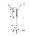
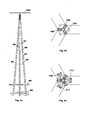
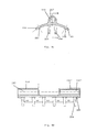
- the in the FIGS. 1a and 1b illustrated support structure consists of a single mast 1 formed from a round timber, a traverse. 2 and two U-profiles 3, 4, which are arranged on opposite sides of the single mast 1, a lower, parallel to the side surface of the single mast 1 extending region and an upper, obliquely outwardly extending region and at the upper ends of the traverse 2 is mounted ,
- the U-profiles 3, 4 are connected to the single mast 1 via in each case an upper composite anchor 5, 6 and a lower composite anchor 7, 8.
- the composite anchors have an elongated core.
- anchor pins are provided which extend perpendicular to the bottom surface of the U-profiles and towards the single mast 1 out.
- the anchor pins engage in recordings 9, 11 provided in the single mast 1.
- the composite anchors 5, 6, 7, 8 are connected to the respective U-profile 3, 4 on at least one side of its core and can simply be screwed or welded, for example, with this on its side facing away from the single mast.
- the core of the composite anchor on at least one bore along its longitudinal axis as a receptacle for a guide pin attached to the U-profile. Examples of such anchors are described with reference to FIGS FIGS. 7a, 7b . 7d . 8th . 9a . 9b . 9c and 9d described.
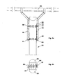
- FIGS. 2a and 2b is another embodiment of a carrier composite system according to the invention, this time with a double mast 31 from two mutually parallel roundwoods 32, 33 shown.
- the logs are held together by means not shown, passing horizontally through them bolts.
- an upper composite anchor 34 and a lower composite anchor 35 are arranged between the round timbers 32, 33.
- Both composite anchors 34, 35 each have a horizontally extending, elongate core 36 whose longitudinal axis is tangent to both roundwoods.
- the composite anchors 34, 35 also have a plurality of mutually parallel anchor pins, which engage on both sides of the core from the outside into corresponding recesses in the round timber.
- Both composite anchors 34, 35 each have at both ends threaded holes in the screws 37, 38, 39, 41 are screwed for fixing U-profiles 42, 43, wherein the U-profiles 42, 43 as in the in FIGS. 1a and 1b embodiment shown above the mast extending Traverse 44 hold.
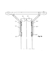
- FIGS. 3a to 3d illustrated carrier composite system differs from that in the FIGS. 1a and 1b merely shown in that instead of the single mast 1, a double mast of two mutually parallel round logs 51, 52 is provided, which are not shown here, by both round logs 51, 51 'horizontally passing bolts are firmly connected to each other, with the U Profiles 52, 52 'connected upper and lower composite anchors 53, 53' engage in the opposite outer sides of the double mast.
- the composite anchors 53, 53 ' are vertical extending through holes provided in the guide pin 54 'engage, which are firmly connected via tabs 55' with the U-profiles 52 'and secured by pins 56' at their free ends against being pulled out.
- both embodiments with double masts can for stabilizing the masts against each other intervening, preferably - as in the FIGS. 3b and 3c shown - vertical, but also horizontally or obliquely arranged composite anchors 57 may be provided which engage with anchoring pins provided on both sides in the masts.
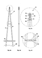
- FIGS. 4a to 4c is a simple mast construction with a vertical single mast 61 shown, which is embedded in the bottom 62 and stabilized at its lower end via a cross member 63.
- the single mast 61 is supported by a likewise inserted into the bottom 62, obliquely attached to the upper end of the single mast 61 strut 64.
- Strut 64 and single mast 61 are connected in the area in which they abut each other via an elongate composite anchor 65 which is vertically arranged and engages with its anchor pins in both the single mast 61, and in the strut 64.
- Strut 64 and single mast 61 are also connected to each other via an upper bolt 66 and a lower bolt 67, so that the composite anchor 65 is secured against slipping out of position.
- FIGS. 5a to 5d another mast construction with an A-mast 71 is shown.
- the two substantially upright running up to each other carrier 72, 73 are in the head region 74 (s. Fig. 7c ) formed flat on their sides facing each other.
- In these Flat areas are recesses for each core and the anchor pins of a first, upper, horizontally extending between the two surfaces of composite anchor 75, a second, arranged underneath, vertically extending composite anchor 76 and a third, under the second composite anchor 76 horizontally extending composite anchor 77 is provided.
- the supports 72, 73 are also connected to each other via horizontally passing therethrough, above and below the and between the composite anchor (s) 75, 76, 77 arranged bolts 78, 79, 81, 82.
- a traverse can be attached to this mast, for example via profiles on the upper and lower composite anchors 75, 77.
- the composite anchors can be provided with through holes passing through their core through holes or frontally with threaded holes, so that the profiles are either to be attached via threaded rods or screws to the composite anchors.
- the carrier 83 has a through hole extending along its longitudinal axis into which a further composite anchor 84 is embedded.
- the composite anchor 84 has threaded bores that cooperate with bolts 85, 86 passing through the beams 72 and 73 and the through hole of the beam 84 and with which the beams 72, 73 are fixedly connected to the cross member 83.
- Both carriers 72, 73 are embedded in the bottom 87 and stabilized in the ground via two horizontal cross bars 88 connecting the carriers 72, 73 and bordering on both sides.
- FIGS. 6a to 6c illustrated mast construction differs from that in the FIGS. 5a to 5d represented essentially in that instead of two substantially upright carriers three carriers 91, 92, 93 are provided, which are arranged in the manner of a three-legged tripod to each other. All carriers are embedded in the bottom 94 and in the ground over parallel, horizontal cross bars 95 in pairs edged and stabilized. Also, the carriers 91, 92, 93 via cross members 97, 98, 99 connected to each other at about half the height of the mast.
- the carriers 91, 92, 93 each have two planar surfaces enclosing an angle of 120 ° as contact surfaces for the respective other two carriers.
- Recesses for the cores and anchor pins of composite anchors 101, 102, 103 are in turn provided in these surfaces which, depending on the embodiment, can optionally be arranged horizontally and / or vertically between the abutting sides of the carriers 91, 92, 93.
- the composite anchors 101, 102, 103 may have threaded holes on their outwardly directed end faces, over which, for example, the in FIG. 6a Traverse 104 shown can be attached to the head of the mast construction.
- a plurality of composite anchors can be arranged one above the other either in horizontal or vertical, possibly also oblique orientation between the abutting surfaces.
- the illustrated three-legged mast construction made of wood is particularly suitable for use for power poles for branches, which are usually carried out so far made of steel.
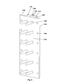
- FIGS. 7a to 7d various types of armature are shown, which can be used for the carrier composite systems according to the invention.
- Fig. 7a shows a composite anchor with a core 111 which has a substantially square cross-section. Through the core 111, a through hole 112 extends. On two adjacent longitudinal sides 113, 114 of the core 111 mutually parallel anchor pins 115 are arranged, the longitudinal axes each form an angle of 45 ° to the respective outer surface on which they are arranged.
- the anchor pins 115 are conical with a tapering away from the core Cross section formed.
- Fig. 7b illustrated composite anchor differs from that in Figure 7a shown only in that are provided at one or both ends of the composite anchor counterbores 121 at the entrance of the through hole for receiving the countersunk heads of countersunk screws.
- the through hole 112 for example, have threads on the front side or can be provided instead of the through hole at one or both ends threaded holes.
- the core can be designed as a solid core without drilling.
- the webs may, instead of lying in a plane perpendicular to the longitudinal axes of the anchor pins, be arranged so that they rest in the installed state, for example on a non-aligned surface of a carrier to which the composite anchor is to be attached.
- the webs can also be curved.
- the armature pins facing away from the outside of the core, which lies between the webs, with the adjoining sides of the webs form a continuous surface and in particular be flat.
- threaded bores for fastening carriers may be provided on the outside of the core facing away from the anchor pins.
- the composite anchors described are particularly suitable for connecting a wooden support, in particular a wooden mast, with a support made of another material, such as steel or concrete.
- Fig. 7c illustrated composite anchor differs from that in Fig. 7a illustrated in that it has a solid core 131 and armature pins 132, 133 are provided on all longitudinal sides of the core 131, wherein the longitudinal axes of the anchor pins with the outside, on which the anchor pins are respectively arranged, again enclose an angle of 45 ° and all in run parallel to each other levels.
- Fig. 7d illustrated composite anchor differs from that in FIG. 7c shown only through a centrally in the longitudinal direction through the core 134 extending through bore 135th
- anchor types with a three-, four- or polygonal core cross section used, at which extending perpendicular to the longitudinal sides anchor pins for simultaneous connection of three or more components are provided.
- Anchor types with anchor pins pointing in several directions are particularly suitable for connecting several wooden beams.
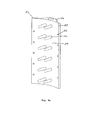
- the illustrated composite anchors differ from those in Figure 7a represented essentially in that its core 141, 151, 151 'and the webs 142, 143, 152, 153 running on both sides of the cores 141, 151, 151' on the side of the anchor pins 144, 154 have a continuous contact surface 145, 155 wherein the cross section of the core 141 in FIG Fig. 8 two to the contact surface 145 perpendicular and mutually parallel side surfaces 147, 148 and the plant surface opposite outer surface 149 having Vietnameseabismeförmigem cross section and the cross section of the core 151, 151 'in the Fig. 9a to 9d is substantially semicircular.
- the webs 142, 143, 152, 153 extend over the entire length of the core 141, 151, 151 'and are provided with a plurality of - in the illustrated examples six - through holes 146, 156.
- the contact surface 145 is flat.
- the through holes 146 are respectively disposed at the height of the anchor pins 144.
- the contact surface 155 of the in the FIGS. 9a to 9d illustrated composite anchor is concave in anchor longitudinal direction, as in particular in the FIGS. 9a and 9c you can see.
- the through holes 156 are disposed at half height of the anchor pins 154, respectively. You can - as in particular in the FIGS. 9b and 9c can be seen - at their the contact surfaces 145, 155 facing away from counterbores 158 for receiving countersunk heads of countersunk screws.
- the semi-circular body of the armature core need not extend over the entire length of the composite anchor. Rather, it may be formed of two or more mutually spaced but mutually aligned anchor portions 151, 151 ', for example, to keep the mass of the composite anchor low (s. FIG. 9d ). If the body of the armature core 151, 151 'is interrupted, it can be used as a receptacle for two guide pins arranged one above the other.
- All illustrated composite anchors are particularly suitable for use on wooden poles. So they can be easily screwed to wooden poles with self-drilling wood screws. This results in particular the advantage that the wood screws record not only acting on the connection of composite anchor and wooden mast tensile forces, but also in addition to the anchor pins thrust and shear forces loads.
- the wood screws do not run parallel but obliquely the anchor pins, in particular when the associated webs of the composite anchor are arranged correspondingly obliquely or its continuous contact surface is curved, take the wood screws tensile forces in different directions, whereby the shear anchor particularly well secured in position and part of the shear and shear forces of the screws is absorbed as tensile forces.
- FIGS. 10a to 10c is a consisting of a guide pin 161 and a tab 162 connecting element shown, which are welded via the tab 162, for example, to a U-beam and can be inserted with its guide pin 161 in the through hole of an armature core.
- the tab 162 is comparatively flat and has in plan view substantially the cross section of an isosceles, right-angled triangle. The right angle opposite end face of the tab 162 serves as a welding edge for welding to a support, such as the aforementioned U-beam.
- At the bottom of the tab 162 of the guide pin 161 is arranged, which has at its free lower end a transverse to its longitudinal axis extending through opening 163 for receiving a Sich ceremoniesssplintes.
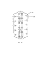
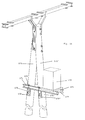
- FIG. 11 shows a further application of the carrier composite system.
- the two masts 171, 171 ' are each at the same height on opposite outer sides of the A-mast piercing anchors 172, 172', in their training in the FIGS. 9a to 9d shown through anchor 172, 172 'correspond, arranged and aligned parallel to the longitudinal axis of the masts 171, 171'.
- the carriers 173, 174 are fixedly connected to the A-mast via bolts 175, 175 'passing through them, which engage in the through bores of the composite anchors 172, 172'. In addition, they are connected at both ends by bolts 176, 177. On one side of the A-mast both beams 173, 174 cantilevered out and form a footprint for a load 178, for example for a transformer.
- FIGS. 9a to 9d illustrated through-anchor above the other and laterally offset from each other.
- a carrier element 184 can be fixedly connected to the mast 181 via guide pins 185, 186 which are fastened to one another via lugs 187, 188 correspondingly one above the other and laterally offset from one another and engage in the push-through anchors 182, 183.
- FIGS. 8 and 9a to 9d illustrated composite anchor and the in FIG. 12 Compound system shown are particularly suitable for attaching a variety of elements or functional parts of poles, such as lighting devices.
Abstract
Description
Die Erfindung betrifft ein Trägerverbundsystem mit mindestens zwei miteinander verbundenen Trägern. Sie betrifft insbesondere eine Mastanordnung.The invention relates to a carrier composite system with at least two interconnected carriers. It relates in particular to a mast arrangement.
In Mittel- und Niederspannungsnetzen werden Holzmastanordnungen verwendet, die Traversen tragen, an denen Stromleitungen befestigt sind. Die Traversen sind üblicherweise Stahlrohre oder Doppel-T-Träger aus Stahl, die mit der Holzmastanordnung über abgewinkelte U-Profile in Verbindung stehen, wobei die U-Profile mit Spangen am oberen Ende der Holzmastanordnung befestigt sind. Die Holzmastanordnung kann aus einem einfachen, im Boden verankerten, aufrechten Holzmast bestehen. Häufig werden auch Holzdoppelmasten verwendet. Die Doppelmasten können beispielsweise in der Form der äußeren Schenkel eines A's angeordnet sein, wobei sie an ihrem oberen Ende von durch sie hindurchgeführten Gewindestangen zusammengehalten werden und darunter in verschiedenen Höhen Querstreben zur Stabilisierung der Masten angeordnet sind. In einer anderen Ausführungsform verlaufen die aus jeweils einem Rundholz gebildeten Masten parallel, wobei Doppel-T-Stücke als Abstandshalter zwischen den Masten vorgesehen sind und die Masten jeweils in Höhe der Doppel-T-Stücke über lange Schraubenbolzen, die horizontal durch die Masten hindurch geführt sind, an die Doppel-T-Stücke angedrückt werden.Medium- and low-voltage networks use wooden pole arrangements that carry trusses to which power lines are attached. The trusses are usually steel tubes or double T-beams made of steel, which are connected to the wooden mast assembly via angled U-profiles, the U-profiles are attached with clips at the top of the wooden pole assembly. The wooden pole arrangement can consist of a simple, anchored in the ground, upright wooden pole. Often also wood double masts are used. The double masts may for example be arranged in the shape of the outer legs of an A's be, wherein they are held together at its upper end by threaded therethrough threaded rods and are arranged underneath at different heights cross struts for stabilizing the masts. In another embodiment, the masts formed from each round timber run parallel, with double T-pieces are provided as spacers between the masts and the masts respectively at the level of the double T-pieces over long bolts that passed horizontally through the mast are pressed to the double tees.
Ein erheblicher Nachteil der bekannten Holzmastkonstruktionen besteht darin, dass ihre Statik nicht berechenbar ist. Ein wesentlicher Grund hierfür ist, dass sich die Holzmasten aufgrund von Änderungen der Umgebungstemperatur und -feuchte unterschiedlich stark ausdehnen. Daher basiert die Auslegung von Holzmasten in bezug auf ihre Dicke sowie der Größe und Art der Verbindungselemente auf empirischen Erfahrungswerten mit dem Nachteil, dass die verwendeten Bauformen nicht wirtschaftlich sind.A considerable disadvantage of the known wooden mast constructions is that their statics can not be calculated. A key reason for this is that the wooden masts expand to different extents due to changes in ambient temperature and humidity. Therefore, the design of wooden poles in terms of their thickness and the size and type of fasteners based on empirical experience with the disadvantage that the types used are not economical.
Demgegenüber liegt der Erfindung die Aufgabe zugrunde, ein Trägerverbundsystem zu schaffen, das statisch berechenbar ist und mit dem Mastanordnungen belastungsgerecht und kostengünstig ausgelegt werden können.In contrast, the invention has for its object to provide a carrier composite system that is statically predictable and can be designed with the mast arrangements load-oriented and cost-effective.
Diese Aufgabe wird mit einem Trägerverbundsystem mit den Merkmalen des Anspruchs 1 gelöst. Bevorzugte Ausführungsformen der Erfindung ergeben sich aus den Unteransprüchen.This object is achieved with a carrier composite system having the features of
Unter einem Verbundanker wird hier und im Folgenden ein Bauelement mit einem Kern verstanden, der eine Vielzahl von Ankerstiften trägt. Der Kern kann eine symmetrische oder asymmetrische Form haben. Als praktisch relevante Kernformen haben sich längliche Kerne mit einem quadratischen oder rautenförmigen Querschnitt herausgestellt. Es sind aber auch als Polyeder ausgebildete Kerne oder andere symmetrisch oder asymmetrisch ausgebildete Kerne verwendbar.A composite anchor is understood here and below to mean a component having a core which carries a large number of anchor pins. The core may have a symmetrical or asymmetrical shape. Elongated cores with a square or diamond-shaped cross section have proven to be practically relevant core shapes. But it can also be used as polyhedron cores or other symmetrical or asymmetrical cores used.
Die Ankerstifte können sich je nach Anwendungsgebiet parallel zueinander nur zu einer Seite hin oder an gegenüberliegenden Seiten des Kerns in entgegengesetzte Richtungen erstrecken. Auch kann ein Verbundanker als Knotenverbindung für zwei oder mehrere Träger mit mindestens zwei in unterschiedliche Richtungen wirkenden Ankerstiftbereichen sein, insbesondere dann, wenn der Kern ein Polyeder ist. Die Anker können je nach Bedarf mit einer oder mehreren Durchgangsbohrungen längs oder quer durch ihren Kern ausgeführt sein und als sogenannte Durchsteckanker als Lager für Gewindestifte dienen. Sie können auch Gewindebohrungen für am Anker zu befestigende Schrauben aufweisen.Depending on the field of application, the anchor pins may extend in opposite directions only parallel to one another or on opposite sides of the core. Also, a composite anchor as a node connection for two or more carriers with at least two acting in different directions anchor pin areas, especially if the core is a polyhedron. The anchors can be designed according to need with one or more through holes longitudinally or transversely through its core and serve as a so-called push-through anchors as a bearing for threaded pins. You can also have threaded holes for screws to be attached to the anchor.
Die Ankerstifte können einen runden oder mehreckigen Querschnitt aufweisen, und insbesondere als Dornen ausgebildet sein. Die Verbundanker können einstückig oder mehrstückig aus einem oder verschiedenen Werkstoffen ausgebildet sein.The anchor pins may have a round or polygonal cross-section, and be formed in particular as thorns. The composite anchors may be integrally or multiply formed from one or different materials.
Es wurde überraschend festgestellt, dass bei Verwendung von mit Ankerstiften versehenen Verbundankern als Verbindungselemente sowohl Zug-und Druckkräfte als auch die zwischen den zu verbindenden Trägern auftretenden Schub- und Scherkräfte besonders gut übertragen werden, da die Ankerstifte die Kräfte nicht an der Außenseite eines Trägers auf diesen übertragen, sondern in sein Inneres einleiten. Hierdurch wird die Krafteinleitung von der geometrischen Ausdehnung des Trägers weitestgehend unabhängig. Eine auf einem derartigen Trägerverbundsystem basierende Mastanordnung ist erstmalig statisch berechenbar, so dass die Auswahl der verwendeten Werkstoffe und die Materialstärken erstmals auf der Basis von Berechnungen zu den zu erwartenden Lastfällen bestimmt werden können.It has surprisingly been found that, when connecting anchors provided with anchor pins, both tensile and compressive forces as well as the shear and shear forces occurring between the carriers to be connected are transferred particularly well as connecting elements, because the anchor pins do not transmit the forces on the outside of a carrier on this, but initiate into its interior. As a result, the introduction of force from the geometric extent of the carrier is largely independent. A mast arrangement based on such a carrier composite system can be statically calculated for the first time, so that the selection of the materials used and the material thicknesses can be determined for the first time on the basis of calculations of the expected load cases.
Die Werkstoffe für die Träger und den Verbundanker können so gewählt sein, dass der Verbundanker in die Außenfläche des Trägers hineingepresst werden kann. Dies ist insbesondere dann möglich, wenn der Mast im Bereich der Ankeraufnahme einen gummiartigen Werkstoff aufweist, der in gewissen Grenzen elastische Eigenschaften besitzt. Insbesondere wenn die Ankerstifte eine oder mehrere Hinterschneidungen aufweisen, so dass sich die durch die Hinterschneidungen gebildeten umlaufenden Kanten des Ankerstiftes in die Oberfläche der durch das Einpressen entstandenen Aufnahme eindrücken, kann der Verbundanker in der Aufnahme fest sitzen.The materials for the beams and the composite anchor can be chosen so that the composite anchor can be pressed into the outer surface of the carrier. This is possible in particular when the mast in the region of the anchor receptacle has a rubber-like material which has elastic properties within certain limits. In particular, when the anchor pins have one or more undercuts, so that the formed by the undercuts circumferential edges of the anchor pin press into the surface of the resulting from the press-fitting, the composite anchor can sit firmly in the recording.
Allerdings werden insbesondere bei Trägern aus Holz bevorzugt Ausnehmungen an der Außenfläche des Trägers vorgesehen, bevor die Ankerstifte des Verbundankers in die Aufnahmen in der Außenfläche des Trägers eingesetzt werden.However, recesses are preferably provided on the outer surface of the carrier, especially in wooden supports before the anchor pins of the composite anchor are inserted into the receptacles in the outer surface of the carrier.
In einer weiteren bevorzugten Ausführungsform der erfindungsgemäßen Tragwerkskonstruktion sind Mittel zum Sichern des in die Aufnahmen in den Außenfläche(n) des bzw. der Träger eingreifenden Verbundankers vorgesehen. Als derartige Mittel kommen insbesondere mechanische Befestigungsmittel, insbesondere Schrauben oder Schraubenbolzen in Betracht, die beispielsweise unmittelbar in den Träger eingreifen, sei es parallel zu den Ankerstiften oder schräg hierzu, wobei die Befestigungsmittel vorzugsweise unmittelbar mit dem Verbundanker in Verbindung stehen. Als Verbindungsmittel kommen aber auch geeignete Klebstoffe, beispielsweise Zwei-Komponenten-Klebstoffe in Betracht.In a further preferred embodiment of the supporting structure construction according to the invention, means are provided for securing the composite anchor engaging in the receptacles in the outer surface (s) of the carrier (s). As such means come in particular mechanical Fastening means, in particular screws or bolts into consideration, for example, engage directly in the carrier, be it parallel to the anchor pins or obliquely thereto, wherein the fastening means are preferably directly in communication with the composite anchor. As connecting agents but also suitable adhesives, for example, two-component adhesives into consideration.
Andere Befestigungsmöglichkeiten bestehen beispielsweise darin, den Verbundanker mit einer um den Verbundanker und den Träger greifenden Schelle am Träger zu befestigen. Auch kann der Verbundanker unmittelbar zwischen zwei oder mehreren Träger liegen, wobei diese Träger untereinander mit weiteren Befestigungsmitteln wie Schrauben, Schellen oder dergleichen zusammen gehalten werden können, so dass der Verbundanker in seiner Position zwischen den Trägern sicher gehalten ist.Other attachment options include, for example, to secure the composite anchor with a cross around the composite anchor and the carrier clamp on the carrier. Also, the composite anchor can lie directly between two or more carriers, these carriers can be held together with other fasteners such as screws, clamps or the like, so that the composite anchor is securely held in position between the carriers.
Insbesondere bei zwei, aber auch bei mehreren aneinander angrenzenden Trägern bietet es sich an, dass der Verbundanker mit Ankerstiften für jeden dieser Träger versehen ist und mit diesen in die Träger eingreift, um eine möglichst gute Überleitung von Kräften von Träger zu Träger zu erreichen.In particular, in two, but also in several mutually adjacent carriers, it makes sense that the composite anchor is provided with anchor pins for each of these carriers and engages with these in the carrier in order to achieve the best possible transfer of forces from carrier to carrier.
Es sind aber ebenso Ausführungsformen bevorzugt, bei denen der Verbundanker lediglich Ankerstifte für einen der zu verbindenden Träger aufweist und mit einem anderen Träger über andere Mittel verbunden ist. So kann ein Verbundanker, der auf der einen Seite mit Ankerstiften in einen Mast eingreift und beispielsweise durch eine Verschraubung am Mast befestigt ist, auf der anderen Seite mit einem eine Traverse tragenden U-Profil beispielsweise über Nieten, eine Verschweißung oder eine Verschraubung verbunden sein.However, embodiments are also preferred in which the composite anchor has only anchor pins for one of the carriers to be connected and is connected to another carrier via other means. Thus, a composite anchor, which engages on one side with anchor pins in a mast and is fastened for example by a screw on the mast, be connected on the other side with a cross-member carrying U-profile, for example via rivets, a weld or a screw.
Wenn die über einen Verbundanker miteinander verbundenen Träger zumindest teilweise aneinander anliegen, ist es von Vorteil, wenn sie in den aneinanderliegenden Bereichen eben ausgebildet sind. Insbesondere dann, wenn die Masten an der Stelle, an der sie aufgestellt werden sollen, erst gefertigt werden, ist das Erzeugen einer ebenen Anlagefläche wesentlich einfacher als das Erstellen einer profilierten Oberfläche.If the carriers connected to one another via a composite anchor at least partially abut each other, it is advantageous if they are flat in the abutting areas. In particular, when the masts are made at the point where they are to be set up, creating a planar abutment surface is much easier than creating a profiled surface.
Die erfindungsgemäße Tragwerkskonstruktion eignet sich, wie sich bereits aus dem Vorstehenden ergibt, besonders gut für Mastanordnungen, insbesondere für solche zur Nutzung als Leitungsmasten in Mittelspannungs-, Niederspannungs- und Hochspannungsnetzen bis 360 kV, oder für solche zur Nutzung in Telekommunikationsnetzen, z.B. Telefonleitungsmasten. Sie können wahlweise mit einer Traverse versehen sein, die über einen oder mehrere Verbundanker mit der Mastanordnung verbunden ist.The structure of the invention is, as already stated above, particularly suitable for mast arrangements, in particular for use as poles in medium-voltage, low-voltage and high-voltage networks up to 360 kV, or for use in telecommunication networks, e.g. Telephone transmission towers. Optionally, they can be provided with a traverse which is connected to the mast arrangement via one or more composite anchors.
Geeignete Mastanordnungen bestehen beispielsweise aus mindestens zwei A-förmig zusammenstehenden, über Verbundanker miteinander verbundenen, aufrechten Trägern. Bevorzugt kann eine Mastanordnung dreibeinig mit drei aufrechten Trägern ausgebildet sein, die über einen oder mehrere Verbundanker miteinander in Verbindung stehen.Suitable mast arrangements consist, for example, of at least two A-shaped, interconnected, interconnected anchors, upright carriers. Preferably, a mast arrangement can be formed in three sockets with three upright carriers, which are connected to one another via one or more composite anchors.
Die erfindungsgemäßen Mastanordnungen können zu ihrer Aussteifung mit Querträgern versehen sein. Solche Querträger können einen innenliegenden Verbundanker, wie er beispielsweise aus der
Das erfindungsgemäße Trägerverbundsystem eignet sich besonders für Träger aus Holz oder einem Holzverbundwerkstoff und ist insbesondere für Tragwerke aus Rundhölzern geeignet. Die Träger können aber ebenso beispielsweise aus einem Kunststoffmaterial, einem Betonwerkstoff oder anderen geeigneten Werkstoffen bestehen.The carrier composite system according to the invention is particularly suitable for carriers made of wood or a wood composite material and is particularly suitable for structures made of round timbers. However, the carriers may also consist, for example, of a plastic material, a concrete material or other suitable materials.
Neben den oben bereits beschriebenen Verbundankern sind auch solche bevorzugt, die mindestens einen Steg mit vorzugsweise mindestens einem Durchgangsloch aufweisen. Die Stege der erfindungsgemäßen Verbundanker können insbesondere dazu dienen, einen in einen (Holz-) Träger eingesetzten und mit seinen Ankerstiften darein eingreifenden Verbundanker mit Schrauben am Träger gegen ein Herausrutschen zu sichern. Dafür können die Form und Ausrichtung der Stege an die Außenfläche eines Trägers, an der sie angelegt werden sollen, angepasst sein. So können sie je nach Anforderung beispielsweise gekrümmt ausgebildet sein oder schräg vom Kern abstehen.In addition to the composite anchors already described above, those which have at least one web, preferably with at least one through-hole, are also preferred. The webs of the composite anchors according to the invention can serve, in particular, to secure a composite anchor inserted into a (wooden) support and engaging it with its anchor pins against the slipping on the support with screws. For this, the shape and orientation of the webs can be adapted to the outer surface of a carrier to which they are to be applied. For example, depending on the requirements, they can be curved or project obliquely from the core.
Auch kann der Verbundanker eine durch eine Außenfläche des Kerns und eine Außenfläche mindestens eines der Stege gebildete, durchgehende Anlagefläche für einen Träger aufweisen, die je nach Anforderung beispielsweise eben oder quer zur Längsachse des Verbundankers gekrümmt ist.Also, the composite anchor may have a continuous contact surface formed by an outer surface of the core and an outer surface of at least one of the webs for a carrier, which is curved, for example, flat or transverse to the longitudinal axis of the composite anchor as required.
In einer weiteren bevorzugten Ausführungsform weist der Verbundanker ein sich in Richtung der Längsachse des Kerns erstreckendes Durchgangsloch, insbesondere eine Durchgangsbohrung, auf. So kann der Anker als Aufnahme für einen Führungs- oder Steckbolzen dienen, über den andere Träger- oder Funktionsteile mit dem Anker verbunden werden können, wie beispielsweise horizontale Tragprofile zur Aufnahme von Transformatoren oder dergleichen. Insbesondere bei Ankerkernen mit Durchgangsbohrung ist es von Vorteil, wenn der Ankerkern mindestens zwei zueinander beabstandete, miteinander fluchtende Ankerkernteile aufweist. So kann auf der einen Seite das zur Herstellung des Ankers benötigte Material und damit auch sein Eigengewicht reduziert werden. Zum anderen bietet eine solche Ausführungsform aber auch den Vorteil, dass ein derart ausgestalteter Verbundanker über mehr als einen Führungs- oder Steckbolzen mit einem oder mehreren Träger- und/oder Funktionselementen verbunden werden kann.In a further preferred embodiment, the composite anchor has a through hole extending in the direction of the longitudinal axis of the core, in particular a through hole. Thus, the anchor can serve as a receptacle for a guide or locking pin over which other carrier or functional parts are connected to the anchor can, such as horizontal support profiles for receiving transformers or the like. In particular, with anchor cores with through-hole, it is advantageous if the armature core has at least two mutually spaced, mutually aligned armature core parts. Thus, on the one hand, the material required for the production of the anchor and thus also its own weight can be reduced. On the other hand, however, such an embodiment also offers the advantage that a composite anchor designed in this way can be connected to one or more support and / or functional elements via more than one guide or locking pin.
Die Verbundanker werden aufgrund der einfachen Formgebung vorzugsweise als Gusstücke hergestellt. Als geeignete Werkstoffe kommen Metalllegierungen in Betracht; es können aber beispielsweise ohne weiteres auch Kunststoffe zum Einsatz kommen.The composite anchors are preferably produced as castings due to the simple shape. Suitable materials are metal alloys into consideration; but it can also be used, for example, readily plastics.
Die Erfindung wird im Folgenden anhand von Figuren, in denen verschiedene bevorzugte Ausführungsformen der Erfindung dargestellt sind, näher erläutert.The invention is explained in more detail below with reference to figures, in which various preferred embodiments of the invention are shown.
Es zeigen:
- Fig. 1a:
- eine Teilansicht eines Trägerverbundsystems mit einem einfachen Holzmast;
- Fig. 1b:
- einen vereinfachten Querschnitt des in
Fig. 1a dargestellten Holzmastes; - Fig. 2a:
- eine Teilansicht eines Trägerverbundsystems mit einem Doppelmast;
- Fig. 2b:
- einen vereinfachten Querschnitt des in
Fig. 2a dargestellten Doppelmastes; - Fig. 3a:
- eine Teilansicht einer anderen Ausführungsform eines Trägerverbundsystems mit einem Doppelmast;
- Fig. 3b:
- einen vereinfachten Querschnitt des in
Fig. 3a dargestellten Doppelmastes; - Fig. 3c:
- eine Teilseitenansicht eines Trägerverbundsystems mit einem Doppelmast wie in
Fig. 3a , jedoch mit einem anderen Verbundanker; - Fig. 3d:
- eine Seitenansicht des in
Fig. 3c dargestellten Doppelmastteils inRichtung Pfeil 3d; - Fig. 4a:
- eine Seitenansicht eines Einfachmastes mit Streben;
- Fig. 4b:
- eine Frontansicht des in
Fig. 4a dargestellten Einzelmastes; - Fig. 4c:
- eine Detailansicht des in
Fig. 4a dargestellten Einzelmastes; - Fig. 5a:
- eine Seitenansicht eines A-Mastes;
- Fig. 5b:
- eine Frontansicht des in
Fig. 5a dargestellten A-Mastes; - Fig. 5c:
- eine Detailansicht des in
Fig. 5a dargestellten A-Mastes; - F9. 5d:
- eine weitere Detailansicht des in
Fig. 5a dargestellten A-Mastes; - Fig. 6a:
- eine Seitenansicht eines dreibeinigen Mastes;
- Fig. 6b:
- einen Querschnitt des Kopfes des in
Fig. 6a dargestellten dreibeinigen Mastes; - Fia. 6c:
- einen weiteren Querschnitt durch den Kopf des in
Fig. 6a dargestellten dreibeinigen Mastes; - Fig. 7a bis 7d:
- isometrische Darstellungen verschiedener für die erfindungsgemäßen Trägerverbundsysteme verwendbarer Verbundankertypen;
- Fig. 8:
- einen für die erfindungsgemäßen Trägerverbundsystem verwendbaren Verbundanker mit einer ebenen, durchgehenden Ankerfläche;
- Fig. 9a:
- einen für die erfindungsgemäßen Trägerverbundsystem verwendbaren Verbundanker mit einer gekrümmten, durchgehenden Ankerfläche in isometrischer Darstellung;
- Fig. 9b:
- eine Aufsicht des in
Figur 9a dargestellten Verbundankers; - Fig. 9c:
- einen Querschnitt des in den
Figuren 9a und9b dargestellten Verbundankers entlang der Linie A-A inFig. 9b ; - Fig. 9d:
- einen Längsschnitt des in den
Figuren 9a bis 9c dargestellten Verbundankers entlang der Linie B-B inFig. 9c ; - Fig. 10a:
- ein in Verbindung mit den Verbundankern verwendbares Verbindungselement in Seitenansicht;
- Fig. 10b:
- das in
Fig. 10a dargestellte Verbindungselement in anderer Seitenansicht; - Fig. 10c:
- das in
Fig. 10a dargestellte Verbindungselement in Aufsicht.; - Fig. 11:
- eine isometrische Darstellung eines oberen Teils eines A-Mastes mit einem daran befestigten Doppelträger für eine Last, insbesondere einen Transformator;
- Fig. 12a:
- eine Seitenansicht eines weiteren Beispiels für eine verbundankerbasierte Befestigung eines insbesondere trägerartigen Elements an einem Holzmast; und
- Fig. 12b:
- eine andere Seitenansicht des in
Fig. 12a dargestellten Beispiels.
- Fig. 1a:
- a partial view of a carrier composite system with a simple wooden mast;
- Fig. 1b:
- a simplified cross-section of the in
Fig. 1a illustrated wooden mast; - Fig. 2a:
- a partial view of a carrier system with a double mast;
- Fig. 2b :
- a simplified cross-section of the in
Fig. 2a illustrated double mast; - Fig. 3a :
- a partial view of another embodiment of a carrier system with a double mast;
- 3b :
- a simplified cross-section of the in
Fig. 3a illustrated double mast; - 3c :
- a partial side view of a carrier composite system with a double mast as in
Fig. 3a but with another composite anchor; - Fig. 3d :
- a side view of the in
Fig. 3c illustrated double mast part in the direction ofarrow 3d; - Fig. 4a :
- a side view of a single mast with struts;
- Fig. 4b :
- a front view of the in
Fig. 4a illustrated single mast; - 4c :
- a detailed view of the in
Fig. 4a illustrated single mast; - Fig. 5a :
- a side view of an A-mast;
- Fig. 5b:
- a front view of the in
Fig. 5a illustrated A-mast; - Fig. 5c:
- a detailed view of the in
Fig. 5a illustrated A-mast; - F9. 5d:
- another detail view of the in
Fig. 5a illustrated A-mast; - 6a:
- a side view of a three-legged mast;
- Fig. 6b:
- a cross section of the head of in
Fig. 6a illustrated three-legged mast; - FIG. 6c:
- another cross section through the head of in
Fig. 6a illustrated three-legged mast; - FIGS. 7a to 7d:
- isometric representations of various types of composite anchor used for the carrier composite systems according to the invention;
- Fig. 8:
- a composite anchor for use with the carrier composite system according to the invention with a flat, continuous anchor surface;
- Fig. 9a:
- a composite anchor for the carrier composite system according to the invention with a curved, continuous anchor surface in isometric view;
- Fig. 9b:
- a supervision of in
FIG. 9a illustrated composite anchor; - Fig. 9c:
- a cross section of the in the
FIGS. 9a and9b illustrated composite anchor along the line AA inFig. 9b ; - Fig. 9d:
- a longitudinal section of the in the
FIGS. 9a to 9c illustrated composite anchor along the line BB inFig. 9c ; - Fig. 10a:
- a usable in connection with the composite anchors connecting element in side view;
- Fig. 10b:
- this in
Fig. 10a illustrated connecting element in another side view; - Fig. 10c :
- this in
Fig. 10a illustrated connecting element in supervision .; - Fig. 11:
- an isometric view of an upper part of an A-mast with an attached double carrier for a load, in particular a transformer;
- Fig. 12a:
- a side view of another example of a Verbundankerbasierte attachment of a particular carrier-like element to a wooden pole; and
- Fig. 12b :
- another side view of the in
Fig. 12a illustrated example.
Die in den
Die U-Profile 3, 4 sind mit dem Einzelmast 1 über jeweils einen oberen Verbundanker 5, 6 und einen unteren Verbundanker 7, 8 verbunden. Die Verbundanker haben einen länglichen Kern. Am Kern sind jeweils acht parallel in zwei Reihen angeordnete Ankerstifte vorgesehen, die sich senkrecht zur Bodenfläche der U-Profile und in Richtung zum Einzelmast 1 hin erstrecken. Die Ankerstifte greifen in hierfür vorgesehene Aufnahmen 9, 11 im Einzelmast 1 ein. Die Verbundanker 5, 6, 7, 8 sind an mindestens einer Seite ihres Kerns mit dem jeweiligen U-Profil 3, 4 verbunden und können beispielsweise mit diesem auf seiner dem Einzelmast abgewandten Seite einfach verschraubt oder verschweißt sein. In einer bevorzugten Ausführung weist der Kern des Verbundankers mindestens eine entlang seiner Längsachse verlaufende Bohrung als Aufnahme für einen am U-Profil befestigten Führungsbolzen auf. Beispiele solcher Anker werden unter Bezugnahme auf die
An den Verbundankern 5, 6, 7, 8 sind parallel zur Außenfläche des Einzelmastes 1 vorgesehene Stege 12, 13, 14, 15 vorgesehen, die als Gegenlager für Schrauben 16, 17, 18, 19, 21, 22, 23, 24, 25, 26, 27 dienen, die in den Einzelmast 1 hineingeschraubt sind, um insbesondere gegen ein Herausrutschen der Verbundanker 5, 6, 7, 8 zu sichern. Die Schrauben erstrecken sich radial in Richtung zur zentralen Längsachse des Einzelmastes 1.At the composite anchors 5, 6, 7, 8 are provided parallel to the outer surface of the
In den
Beide Verbundanker 34, 35 weisen jeweils an beiden Stirnseiten Gewindebohrungen auf, in die Schrauben 37, 38, 39, 41 zur Befestigung von U-Profilen 42, 43 eingeschraubt sind, wobei die U-Profile 42, 43 wie bei der in den
Das in den
Bei beiden Ausführungsformen mit Doppelmasten können zur Stabilisierung der Masten gegeneinander dazwischen liegende, vorzugsweise - wie in den
In den
In den
Eine Traverse kann an diesem Mast beispielsweise über Profile am oberen und unteren Verbundanker 75, 77 befestigt werden. Hierfür können die Verbundanker mit durch ihren Kern hindurchlaufenden Durchgangsbohrungen oder stirnseitig mit Gewindebohrungen versehen sein, so dass die Profile wahlweise über Gewindestangen oder Schrauben an den Verbundankern zu befestigen sind.A traverse can be attached to this mast, for example via profiles on the upper and lower composite anchors 75, 77. For this purpose, the composite anchors can be provided with through holes passing through their core through holes or frontally with threaded holes, so that the profiles are either to be attached via threaded rods or screws to the composite anchors.
Auf etwa halber Höhe des A-Mastes 71 ist ein zwischen den Trägern 72, 73 horizontal verlaufender Träger 83 vorgesehen, der in der Detailansicht der
Beide Träger 72, 73 sind in den Boden 87 eingelassen und im Boden über zwei die Träger 72, 73 verbindende und von beiden Seiten einfassende, horizontale Querstäbe 88 stabilisiert.Both
Die in den
An ihren oberen Enden weisen die Träger 91, 92, 93 jeweils zwei ebene, einen Winkel von 120° einschließende Flächen als Anlageflächen für die jeweils anderen beiden Träger auf. In diese Flächen sind wiederum Ausnehmungen für die Kerne und Ankerstifte von Verbundankern 101, 102, 103 vorgesehen, die je nach Ausführungsform wahlweise horizontal und oder vertikal zwischen den aneinander anliegenden Seiten der Träger 91, 92, 93 angeordnet sein können. Sind die Verbundanker - wie in der Detailansicht der
Wie auch in dem in den
Wie sich insbesondere dem in
Die dargestellte dreibeinige Mastkonstruktion aus Holz ist insbesondere zur Verwendung für Strommaste für Abzweigungen geeignet, die bislang in aller Regel aus Stahl ausgeführt werden.The illustrated three-legged mast construction made of wood is particularly suitable for use for power poles for branches, which are usually carried out so far made of steel.
In den
Der in
Das Prinzip dieser Verbundanker mit nur zu einer Seite hin weisenden Ankerstiften kann vielfältig variiert werden. So kann die Durchgangsbohrung 112 beispielsweise stirnseitig Gewinde aufweisen oder können statt der Durchgangsbohrung an einer oder beiden Stirnseiten Gewindelöcher vorgesehen sein. Auch kann der Kern als Vollkern ohne Bohrung ausgeführt sein. Die Stege können, anstatt in einer Ebene senkrecht zu den Längsachsen der Ankerstifte zu liegen, so angeordnet sein, dass sie in eingebautem Zustand, z.B. an einer nicht fluchtenden Fläche eines Trägers, an dem der Verbundanker befestigt werden soll, anliegen. Hierfür können die Stege auch gekrümmt sein. Auch kann die den Ankerstiften abgewandte Außenseite des Kerns, die zwischen den Stegen liegt, mit den daran angrenzenden Seiten der Stege eine durchgehende Fläche bilden und insbesondere eben ausgebildet sein. Des weiteren können an der den Ankerstiften abgewandten Außenseite des Kerns Gewindebohrungen zur Befestigung von Trägern vorgesehen sein.The principle of this composite anchor with only one side facing anchor pins can be varied varied. Thus, the through
Die beschriebenen Verbundanker eignen sich insbesondere zur Verbindung eines Holzträgers, insbesondere eines Holzmastes, mit einem Träger aus einem anderen Werkstoff, wie beispielsweise Stahl oder Beton.The composite anchors described are particularly suitable for connecting a wooden support, in particular a wooden mast, with a support made of another material, such as steel or concrete.
Der in
Der in
Auch die beiden zuletzt beschriebenen Ankertypen sind ebenso wie die zuvor beschriebenen vielfach variierbar, insbesondere hinsichtlich der Anzahl, Anordnung und Ausgestaltung von Durchgangslöchern, -bohrungen, und Ankerstiften, sowie der Ausgestaltung des Kernquerschnitts, und eignen sich insbesondere zur Verbindung zweier Holzträger.The last two types of anchor described above are often varied as well as the previously described, in particular with regard to the number, arrangement and design of through holes, holes, and anchor pins, as well as the design of the core cross-section, and are particularly suitable for connecting two wooden beams.
Meist reichen zur sicheren Übertragung von Schub- und Scherkräften 1 bis 3 Verbundanker je aneinander anliegendem Flächenpaar benachbarter Träger aus. Die tatsächliche, auch darüber hinaus benötigte Anzahl von Verbundanker je Flächenpaar wird sich jedoch immer aus den zu erwartenden statischen und gegebenenfalls auch dynamischen Lasten ergeben.Usually sufficient for safe transmission of shear and
Es sind auch Ankertypen mit einem drei-, vier- oder mehreckigen Kernquerschnitt einsetzbar, an denen senkrecht zu den Längsseiten erstreckende Ankerstifte zur gleichzeitigen Verbindung dreier oder mehrerer Bauteile vorgesehen sind. Ankertypen mit in mehrere Richtungen weisenden Ankerstiften eignen sich insbesondere zur Verbindung von mehreren Holzträgern.There are also anchor types with a three-, four- or polygonal core cross section used, at which extending perpendicular to the longitudinal sides anchor pins for simultaneous connection of three or more components are provided. Anchor types with anchor pins pointing in several directions are particularly suitable for connecting several wooden beams.
Die in den
Beide Ankerkerne 141, 151, 151' weisen in Richtung ihrer Längsachse verlaufende Durchgangsbohrungen 150, 157 auf.Both
Bei dem in
Die Anlagefläche 155 des in den
Der halbkreisförmige Körper des Ankerkerns muss sich nicht über die gesamte Länge des Verbundankers erstrecken. Vielmehr kann er aus zwei oder mehreren voneinander beabstandeten, aber miteinander fluchtenden Ankerteilen 151, 151' ausgebildet sein, beispielsweise um die Masse des Verbundankers gering zu halten (s.
Alle dargestellten Verbundanker eignen sich insbesondere zur Verwendung an Holzmasten. So können sie mit selbstbohrenden Holzschrauben einfach an Holzmasten festgeschraubt werden. Hierdurch ergibt sich insbesondere der Vorteil, dass die Holzschrauben nicht nur auf die Verbindung von Verbundanker und Holzmast wirkende Zugkräfte, sondern auch in Ergänzung zu den Ankerstiften Schub- und Scherkraftlasten aufnehmen. Verlaufen die Holzschrauben dabei nicht parallel, sondern schräg zu den Ankerstiften, insbesondere dann, wenn die zugehörigen Stege des Verbundankers entsprechend schräg angeordnet sind oder seine durchgehende Anlagefläche gekrümmt ist, nehmen die Holzschrauben Zugkräfte in unterschiedlichen Richtungen auf, wodurch der Verbundanker besonders gut in seiner Position gesichert und ein Teil der Schub- und Scherkräfte von den Schrauben als Zugkräfte aufgenommen wird.All illustrated composite anchors are particularly suitable for use on wooden poles. So they can be easily screwed to wooden poles with self-drilling wood screws. This results in particular the advantage that the wood screws record not only acting on the connection of composite anchor and wooden mast tensile forces, but also in addition to the anchor pins thrust and shear forces loads. The wood screws do not run parallel but obliquely the anchor pins, in particular when the associated webs of the composite anchor are arranged correspondingly obliquely or its continuous contact surface is curved, take the wood screws tensile forces in different directions, whereby the shear anchor particularly well secured in position and part of the shear and shear forces of the screws is absorbed as tensile forces.
In den
In den
Die in den
Claims (18)
Applications Claiming Priority (3)
| Application Number | Priority Date | Filing Date | Title |
|---|---|---|---|
| DE200610018089 DE102006018089A1 (en) | 2006-04-18 | 2006-04-18 | Carrier composite system e.g. mast arrangement has two carrier connected with each other, and shear connector is provided with armature pins, which engages in outer side of carrier for connection of carriers with armature pins |
| DE202006016481U DE202006016481U1 (en) | 2006-04-18 | 2006-10-24 | Carrier composite system |
| EP07724262A EP2010737A1 (en) | 2006-04-18 | 2007-04-16 | Carrier connection system |
Related Parent Applications (1)
| Application Number | Title | Priority Date | Filing Date |
|---|---|---|---|
| EP07724262A Division EP2010737A1 (en) | 2006-04-18 | 2007-04-16 | Carrier connection system |
Publications (2)
| Publication Number | Publication Date |
|---|---|
| EP2698488A2 true EP2698488A2 (en) | 2014-02-19 |
| EP2698488A3 EP2698488A3 (en) | 2014-04-16 |
Family
ID=38218900
Family Applications (2)
| Application Number | Title | Priority Date | Filing Date |
|---|---|---|---|
| EP13183534.0A Withdrawn EP2698488A3 (en) | 2006-04-18 | 2007-04-16 | Carrier connection system |
| EP07724262A Withdrawn EP2010737A1 (en) | 2006-04-18 | 2007-04-16 | Carrier connection system |
Family Applications After (1)
| Application Number | Title | Priority Date | Filing Date |
|---|---|---|---|
| EP07724262A Withdrawn EP2010737A1 (en) | 2006-04-18 | 2007-04-16 | Carrier connection system |
Country Status (3)
| Country | Link |
|---|---|
| EP (2) | EP2698488A3 (en) |
| DE (1) | DE202006016481U1 (en) |
| WO (1) | WO2007121881A1 (en) |
Cited By (1)
| Publication number | Priority date | Publication date | Assignee | Title |
|---|---|---|---|---|
| DE102017002557A1 (en) | 2017-03-17 | 2018-09-20 | Carl Scholl Gmbh | Mounting set and mast arrangement that can be provided with it |
Families Citing this family (10)
| Publication number | Priority date | Publication date | Assignee | Title |
|---|---|---|---|---|
| DE102007033829A1 (en) * | 2007-07-18 | 2009-01-22 | Induo Gesellschaft Zur Verwertung Von Schutzrechten Mbh & Co. Kg | mast assembly |
| DE102008009056A1 (en) | 2008-02-13 | 2009-08-20 | Induo Gesellschaft Zur Verwertung Von Schutzrechten Mbh & Co. Kg | Xings |
| DE102010018646A1 (en) | 2010-04-28 | 2011-11-03 | Induo Gesellschaft Zur Verwertung Von Schutzrechten Mbh & Co Kg | mast anchoring |
| DE102012101002A1 (en) | 2011-06-08 | 2012-12-13 | Induo Gesellschaft Zur Verwertung Von Schutzrechten Mbh & Co. Kg | Traverse arrangement, in particular for overhead transmission masts |
| DE202012100412U1 (en) * | 2011-09-01 | 2012-12-05 | Induo Gesellschaft Zur Verwertung Von Schutzrechten Mbh & Co. Kg | mast assembly |
| DE202012008305U1 (en) | 2012-08-30 | 2012-09-26 | Db Netz Ag | Mast construction for track-bound overhead line systems of rail transport |
| DE102012017164A1 (en) | 2012-08-30 | 2014-03-06 | Db Netz Ag | Two-part mast structure for track-bound overhead line system for electrically operated rail- or drive-bound transportation unit, has upper mast part designed as carbon fiber reinforced plastic- or wooden-plastic composite material |
| CN103452370B (en) | 2012-10-25 | 2015-12-16 | 江苏神马电力股份有限公司 | Power grid transmission line complex pole tower and compound cross-arm structure thereof |
| DE202013105485U1 (en) | 2013-12-02 | 2015-03-03 | Induo Gesellschaft Zur Verwertung Von Schutzrechten Mbh & Co. Kg | Connection for mast braid |
| DE102019113971A1 (en) * | 2019-05-24 | 2020-11-26 | Westnetz Gmbh | Power and / or telecommunications mast with mast bracket |
Citations (1)
| Publication number | Priority date | Publication date | Assignee | Title |
|---|---|---|---|---|
| DE29723866U1 (en) | 1997-01-17 | 1999-04-15 | Morze Reichartz Sigrun Von | Fastener |
Family Cites Families (12)
| Publication number | Priority date | Publication date | Assignee | Title |
|---|---|---|---|---|
| GB189760A (en) * | 1921-12-01 | 1923-03-29 | Himmelsbach Ag Gebr | Improvements in posts |
| US2762091A (en) * | 1952-04-16 | 1956-09-11 | Malleable Iron Fittings Co | Washer gain for timber structures formed of round wood poles |
| US2969859A (en) * | 1958-04-22 | 1961-01-31 | Malleable Iron Fittings Co | Cross arm supporting gain |
| DE2522912A1 (en) * | 1975-05-23 | 1976-12-02 | Wilhelm Buddemeier | Lattice and frame structure connecting dowelling plate - made of sheet steel with welded dowel plugs let into upright planking |
| NO814164L (en) * | 1981-12-04 | 1983-06-06 | Bulldog As | TOEMMERFORBINDELSER. |
| AU2294583A (en) * | 1983-01-21 | 1984-07-26 | Gang-Nails N.Z. Ltd. | Nail plate |
| DE8814106U1 (en) * | 1988-10-26 | 1989-03-09 | Gang-Nail Systeme Gmbh, 8000 Muenchen, De | |
| DE19701458C1 (en) * | 1997-01-17 | 1998-09-03 | Morze Reichartz Sigrun Von | Support structure, particularly for buildings |
| US5966892A (en) * | 1997-01-27 | 1999-10-19 | Platt; R. Terry | Ready to assemble wood construction system |
| DE10110799A1 (en) * | 2001-03-06 | 2002-09-12 | Raico Bautechnik Gmbh | Locked connection between two construction component units, at right angles to each other, has locking profiles at each to be clamped in place by wedges pulled together by a screw bolt |
| DE20120208U1 (en) * | 2001-12-13 | 2003-04-24 | Sfs Intec Holding Ag Heerbrugg | Connection of posts and transoms made of wooden beams or slats to form wall elements |
| DE20306942U1 (en) * | 2003-05-06 | 2003-07-31 | Induo Ges Zur Verwertung Von S | System of interconnected components |
-
2006
- 2006-10-24 DE DE202006016481U patent/DE202006016481U1/en not_active Expired - Lifetime
-
2007
- 2007-04-16 EP EP13183534.0A patent/EP2698488A3/en not_active Withdrawn
- 2007-04-16 WO PCT/EP2007/003324 patent/WO2007121881A1/en active Application Filing
- 2007-04-16 EP EP07724262A patent/EP2010737A1/en not_active Withdrawn
Patent Citations (1)
| Publication number | Priority date | Publication date | Assignee | Title |
|---|---|---|---|---|
| DE29723866U1 (en) | 1997-01-17 | 1999-04-15 | Morze Reichartz Sigrun Von | Fastener |
Cited By (1)
| Publication number | Priority date | Publication date | Assignee | Title |
|---|---|---|---|---|
| DE102017002557A1 (en) | 2017-03-17 | 2018-09-20 | Carl Scholl Gmbh | Mounting set and mast arrangement that can be provided with it |
Also Published As
| Publication number | Publication date |
|---|---|
| EP2010737A1 (en) | 2009-01-07 |
| DE202006016481U1 (en) | 2007-08-30 |
| EP2698488A3 (en) | 2014-04-16 |
| WO2007121881A1 (en) | 2007-11-01 |
Similar Documents
| Publication | Publication Date | Title |
|---|---|---|
| EP2698488A2 (en) | Carrier connection system | |
| EP2165030B1 (en) | Mast arrangement | |
| EP2253764B1 (en) | Frame-shaped truss | |
| EP1977935A2 (en) | Motor vehicle framework and crashbox therefor | |
| DE102014107323A1 (en) | Crane carrier for a crane, in particular for a bridge or gantry crane, and a crane hereby | |
| EP3743567B1 (en) | Variable container system | |
| DE2526660C3 (en) | Building construction with a space framework made of bars and junction pieces and an outer skin | |
| DE2206973A1 (en) | SPATIAL ELEMENT FOR THE FORMATION OF STRUCTURES OF ALL KINDS | |
| EP2954125B1 (en) | Wooden support construction comprising a strut-type or planar support element and at least one second strut-type or planar support element | |
| EP1932978B1 (en) | Reinforcing element for absorbing forces in concreted slabs in the area of supporting elements | |
| EP0596207A1 (en) | Sheet metal, preferably cold rolled section for the construction of supporting frameworks, platforms or the like | |
| DE102006018089A1 (en) | Carrier composite system e.g. mast arrangement has two carrier connected with each other, and shear connector is provided with armature pins, which engages in outer side of carrier for connection of carriers with armature pins | |
| EP2383406A2 (en) | Mast anchoring | |
| DE10051793A1 (en) | Wood connector between beams has shaped sheet steel part with fixing flange and two bearing flanges and inclined fastening means extending from top of secondary support inclined through up into main support | |
| EP1878859A2 (en) | Connecting element for fence crossbar and fence post | |
| DE202005006228U1 (en) | Roof construction for buildings, especially industrial buildings with large widths, comprises bottom and top booms in the form of I-shaped supports with two boom flanges, and node elements with two flat node flange plates | |
| EP3427851A1 (en) | Construction profile and combination profile consisting of at least two construction profiles and guard rail bracket | |
| DE102016118014A1 (en) | Trusses, in particular roof trusses for a hall | |
| DE4021937C1 (en) | Load distributing platform for groove support legs - has continuous parallel struts with several pressure or tensile supports in between | |
| EP1936054B1 (en) | Tension plate for mounting porous concrete wall panels and porous concrete wall panel system with tension plates | |
| DE2626407A1 (en) | Platform or shelving connector - has plug and socket with contours matching main stress line orthogonal trajectories | |
| DE10253743B4 (en) | Device for connecting monorail profiles for hoists | |
| EP2998450B1 (en) | Connection element | |
| DE202013105485U1 (en) | Connection for mast braid | |
| EP2565349A2 (en) | Mast assembly |
Legal Events
| Date | Code | Title | Description |
|---|---|---|---|
| AC | Divisional application: reference to earlier application |
Ref document number: 2010737 Country of ref document: EP Kind code of ref document: P |
|
| AK | Designated contracting states |
Kind code of ref document: A2 Designated state(s): AT BE BG CH CY CZ DE DK EE ES FI FR GB GR HU IE IS IT LI LT LU LV MC MT NL PL PT RO SE SI SK TR |
|
| PUAI | Public reference made under article 153(3) epc to a published international application that has entered the european phase |
Free format text: ORIGINAL CODE: 0009012 |
|
| PUAL | Search report despatched |
Free format text: ORIGINAL CODE: 0009013 |
|
| AK | Designated contracting states |
Kind code of ref document: A3 Designated state(s): AT BE BG CH CY CZ DE DK EE ES FI FR GB GR HU IE IS IT LI LT LU LV MC MT NL PL PT RO SE SI SK TR |
|
| RIC1 | Information provided on ipc code assigned before grant |
Ipc: E04H 12/04 20060101AFI20140311BHEP |
|
| 17P | Request for examination filed |
Effective date: 20141016 |
|
| RBV | Designated contracting states (corrected) |
Designated state(s): AT BE BG CH CY CZ DE DK EE ES FI FR GB GR HU IE IS IT LI LT LU LV MC MT NL PL PT RO SE SI SK TR |
|
| STAA | Information on the status of an ep patent application or granted ep patent |
Free format text: STATUS: THE APPLICATION IS DEEMED TO BE WITHDRAWN |
|
| 18D | Application deemed to be withdrawn |
Effective date: 20151103 |