EP2698306A2 - Drainage plug - Google Patents
Drainage plug Download PDFInfo
- Publication number
- EP2698306A2 EP2698306A2 EP13179626.0A EP13179626A EP2698306A2 EP 2698306 A2 EP2698306 A2 EP 2698306A2 EP 13179626 A EP13179626 A EP 13179626A EP 2698306 A2 EP2698306 A2 EP 2698306A2
- Authority
- EP
- European Patent Office
- Prior art keywords
- sealing element
- opening
- base body
- drainage plug
- cavity
- Prior art date
- Legal status (The legal status is an assumption and is not a legal conclusion. Google has not performed a legal analysis and makes no representation as to the accuracy of the status listed.)
- Granted
Links
- 238000007789 sealing Methods 0.000 claims abstract description 70
- 239000011796 hollow space material Substances 0.000 abstract 1
- XLYOFNOQVPJJNP-UHFFFAOYSA-N water Substances O XLYOFNOQVPJJNP-UHFFFAOYSA-N 0.000 description 15
- 239000007788 liquid Substances 0.000 description 4
- 230000005484 gravity Effects 0.000 description 3
- 238000011109 contamination Methods 0.000 description 2
- 239000004575 stone Substances 0.000 description 2
- 210000000476 body water Anatomy 0.000 description 1
- 230000035515 penetration Effects 0.000 description 1
Images


Classifications
-
- B—PERFORMING OPERATIONS; TRANSPORTING
- B62—LAND VEHICLES FOR TRAVELLING OTHERWISE THAN ON RAILS
- B62D—MOTOR VEHICLES; TRAILERS
- B62D25/00—Superstructure or monocoque structure sub-units; Parts or details thereof not otherwise provided for
- B62D25/20—Floors or bottom sub-units
-
- B—PERFORMING OPERATIONS; TRANSPORTING
- B60—VEHICLES IN GENERAL
- B60R—VEHICLES, VEHICLE FITTINGS, OR VEHICLE PARTS, NOT OTHERWISE PROVIDED FOR
- B60R13/00—Elements for body-finishing, identifying, or decorating; Arrangements or adaptations for advertising purposes
- B60R13/07—Water drainage or guide means not integral with roof structure
-
- B—PERFORMING OPERATIONS; TRANSPORTING
- B62—LAND VEHICLES FOR TRAVELLING OTHERWISE THAN ON RAILS
- B62D—MOTOR VEHICLES; TRAILERS
- B62D25/00—Superstructure or monocoque structure sub-units; Parts or details thereof not otherwise provided for
- B62D25/24—Superstructure sub-units with access or drainage openings having movable or removable closures; Sealing means therefor
-
- F—MECHANICAL ENGINEERING; LIGHTING; HEATING; WEAPONS; BLASTING
- F16—ENGINEERING ELEMENTS AND UNITS; GENERAL MEASURES FOR PRODUCING AND MAINTAINING EFFECTIVE FUNCTIONING OF MACHINES OR INSTALLATIONS; THERMAL INSULATION IN GENERAL
- F16K—VALVES; TAPS; COCKS; ACTUATING-FLOATS; DEVICES FOR VENTING OR AERATING
- F16K15/00—Check valves
- F16K15/02—Check valves with guided rigid valve members
- F16K15/03—Check valves with guided rigid valve members with a hinged closure member or with a pivoted closure member
Definitions
- the invention relates to a drainage plug for a cavity of a vehicle, in particular for a side sill, having a base body which can be fixed in an opening of the side sill and having an opening in which a sealing element is arranged between a closed position in which the opening is tightly closed, and an opening position in which the opening is opened, can be moved.
- drainage holes are provided to drain water that may accumulate in the cavity.
- drainage plugs are provided which can close the drainage opening while driving and stand the drainage opening are open to drain water collected in the cavity.
- the drain plug has a body that can be inserted into the opening of the cavity.
- a movable sealing member is arranged, which can be moved between a closed position and an open position.
- this sealing element is usually held in the open position by gravity or a small spring bias, so that water can flow out of the cavity.
- driving the sealing element is moved by pressure differences on the outside and the inside of the cavity in the closed position, so that the breakthrough while driving the vehicle is tightly closed and penetration of moisture or dirt is prevented.
- Such a drainage plug is for example from the DE 10 2007 026 543 A1 known.
- the sealing element is mounted centrally on a vertical pin on the base body and is moved vertically upwards into the closed position.
- an additional covering element is provided which protects the sealing element from, for example, stone chipping.
- the sealing element has a very large contact surface on the body. This can lead to leaks if stones or dirt get between the base body and the sealing element.
- the sealing element is completely displaced, which can lead to jamming of the pin under unfavorable circumstances, so that the opening can not be completely sealed.
- the object of the invention is to provide a drainage plug for a cavity of a vehicle, in particular for a side sill, which has a simpler structure and ensures a reliable seal of the opening.
- a drainage plug for a cavity of a vehicle in particular for a side skirt, is provided, with a base body which can be fixed in an opening of the side sill and having an opening in which a sealing element is arranged, which is disposed between a closed position, in which the opening is tightly closed, and an opening position in which the opening is opened, can be moved.
- the sealing element is mounted pivotably about a holding axis on the base body.
- the sealing element is pivoted so that liquid can flow off over the obliquely placed in the opening position sealing element, whereby dirt that accumulates between the sealing element and the body can be washed away with the liquid.
- a more reliable sealing of the opening in the body is possible.
- a receptacle may be provided on the base body or on the sealing element, in the at least one provided on the sealing element or on the main body retaining bolt is pivotally mounted.
- the receptacle can have a clip or latching connection for the bolt so that it can be mounted without additional tools. This also facilitates the replacement of the sealing element, for example in the event of damage to the sealing element.
- a circumferential sealing edge is provided, against which the sealing element abuts circumferentially in the closed position.
- the sealing edge is preferably arranged on an outer side of the main body, and the sealing element is pivoted away from the outside in the open position.
- the drainage plug is located at the lowest point of the cavity, for example a side sill.
- the sealing element is thus, when it is pivoted away from the outside, pivoted vertically downwards.
- the sealing element is moved by gravity into the open position, so that when the vehicle is stopped automatically opening of the dewatering plug and thus an outflow of water can be done.
- the sealing edge can not form an upwardly directed groove in which water could collect.
- a wind deflector in particular a spoiler
- a spoiler may be provided on the main body.
- the spoiler or the Windabweisers on the outside of the body water or dirt can be deflected away by the wind from the drainage hole, so that ingress of dirt into the opening or contamination of the drainage plug is prevented.
- the spoiler can influence the pressure conditions at the drainage opening in such a way that the closing of the drainage stopper is supported while driving.
- the wind deflector is preferably arranged in the mounted state of the dewatering plug in a direction of travel of the vehicle in front of the opening.
- the base body and / or the sealing element are made, for example, of plastic, in particular of TPE.
- a drain plug 10 is shown that can be inserted into a breakthrough 12 of a vehicle part, here a side sill 14 of a vehicle (see also FIG Figures 2 and 3 ).
- a side sill 14 of a vehicle see also FIG Figures 2 and 3 .
- water may accumulate during operation of the vehicle, which can flow out of the cavity 16 through the opening 12.
- the drain plug 10 closes the aperture 12 during vehicle driving so that ingress of dirt or moisture into the cavity 16 during travel can be prevented. When the vehicle is stationary, the drainage plug 10 opens so that liquid and dirt can flow out of the cavity 16.
- the drainage plug 10 has a base body 18 which can be inserted into the opening 12 and has an opening 20. Furthermore, the drainage plug 10 has a sealing element 22, which, as will be shown below, is mounted pivotably on the base body 18 and between a closed position (FIG. FIG. 2 ), in which the opening 20 is sealed, and an opening position ( FIG. 3 ), in which liquid can flow out of the opening 20, can be moved.
- the base body 18 has a surrounding the opening 20 frame 24 on which a sealing lip 26 is provided, which abuts the opening 12 of the side sill 14 circumferentially, and locking elements 28, with which the main body 18 on the back of the side sill 14 can be locked.
- the main body 18 further comprises a receptacle 30, which is designed here as a latching connection, and in which the sealing element 22 can be clipped.
- a receptacle 30 which is designed here as a latching connection, and in which the sealing element 22 can be clipped.
- bearing surfaces 32 are also provided, which can guide the sealing element 22 when moving in the closed position.
- the sealing element 22 has a bolt or a projection 34 which can be inserted into the receptacle 30 on the base body 18 and latched thereto.
- the sealing element 22 is trough-shaped in the embodiment shown here, so that this, as in the Figures 2 and 3 can be seen concavely to the inside or to the cavity 16 is curved.
- the sealing element 22 is pivotally mounted about a support shaft 36 which is formed here by the projection 34.
- the sealing element In a stationary vehicle, the sealing element is due to gravity FIG. 3 moved down to the open position, so that water can flow out of the cavity 16.
- the sealing element 22 In the open position, the sealing element 22 is relative to FIG. 3 pivoted counterclockwise about the support shaft 36 so that the opening 20 is opened and water can flow out of the cavity 16.
- 18 further recesses 44 are provided at the opening 20 of the base body, which are sealed by the sealing member 22, in the opening position of the sealing member 22 but the drainage of water from wells of the body 18, for example, behind the sealing lip 26 allow.
- the sealing element 22 When driving, the sealing element 22 is due to the resulting pressure difference between the cavity 16 and the outside of the side sill 14 with respect to the Figures 2 and 3 moved upward or clockwise in the closed position, so that during the drive of the vehicle, the cavity 16 is sealed and the ingress of dirt and water can be prevented.
- the sealing element 22 rests with a rim 38 circumferentially on a sealing edge 40 of the base body 18 and thus seals the opening 20 in the base body 18 fluid-tight, so that the ingress of dirt or water is prevented in the cavity 16.
- the sealing element 22 In the closed position, the sealing element 22 also abuts against the contact surfaces 32 of the main body 18. These stabilize the sealing element 22, so that no leaks can occur due to deformation of the sealing element 22. In addition, when pivoting into the closed position, a centering of the sealing element 22 takes place automatically.
- a wind deflector 42 is further provided, which is arranged in a direction of travel F in front of the opening 20 and thus in front of the sealing element 22.
- the wind deflector 42 deflects the air flow while driving in addition so that the sealing element 22 is additionally urged into the closed position and water or dirt are deflected away from the opening 20 and the sealing member 22 so that contamination of the opening 20 and the Seal member 22, which could lead to a reduced seal, is prevented.
- the wind deflector 42 is arranged in the embodiment shown here in the direction of travel in front of the sealing element 22, but the wind deflector 42 could also be arranged at a different position of the base body 18. It is only necessary to ensure that this dirt and water from the opening 20 and the sealing member 22 deflects.
Abstract
Description
Die Erfindung betrifft einen Entwässerungsstopfen für einen Hohlraum eines Fahrzeugs, insbesondere für einen Seitenschweller, mit einem Grundkörper, der in einem Durchbruch des Seitenschwellers fixiert werden kann und eine Öffnung aufweist, in der ein Dichtungselement angeordnet ist, das zwischen einer Schließposition, in der die Öffnung dicht geschlossen ist, und einer Öffnungsposition, in der die Öffnung geöffnet ist, bewegt werden kann.The invention relates to a drainage plug for a cavity of a vehicle, in particular for a side sill, having a base body which can be fixed in an opening of the side sill and having an opening in which a sealing element is arranged between a closed position in which the opening is tightly closed, and an opening position in which the opening is opened, can be moved.
In den Hohlräumen eines Fahrzeugs beispielsweise in den Seitenschweller, sind Entwässerungsöffnungen vorgesehen, um Wasser, das sich im Hohlraum sammeln kann, abfließen zu lassen. Um während der Fahrt ein Eindringen von Feuchtigkeit oder Schmutz in den Hohlraum zu verhindern, sind Entwässerungsstopfen vorgesehen, die die Entwässerungsöffnung während der Fahrt verschließen können und im Stand die Entwässerungsöffnung offen sind, um im Hohlraum gesammeltes Wasser abfließen zu lassen.In the cavities of a vehicle, for example, in the side skirts, drainage holes are provided to drain water that may accumulate in the cavity. In order to prevent the ingress of moisture or dirt into the cavity during driving, drainage plugs are provided which can close the drainage opening while driving and stand the drainage opening are open to drain water collected in the cavity.
Der Entwässerungsstopfen weist einen Grundkörper auf, der in den Durchbruch des Hohlraums eingesetzt werden kann. In diesem Grundkörper ist ein bewegliches Dichtungselement angeordnet, das zwischen einer Schließposition und einer Öffnungsposition bewegt werden kann. Im Stillstand des Fahrzeugs wird dieses Dichtungselement üblicherweise durch die Schwerkraft oder eine geringe Federvorspannung in der geöffneten Position gehalten, sodass Wasser aus dem Hohlraum abfließen kann. Im Fahrbetrieb wird das Dichtungselement durch Druckunterschiede auf der Außenseite und der Innenseite des Hohlraum in die Schließposition bewegt, sodass der Durchbruch während der Fahrt des Fahrzeugs dicht geschlossen ist und ein Eindringen von Feuchtigkeit oder Schmutz verhindert ist.The drain plug has a body that can be inserted into the opening of the cavity. In this base body, a movable sealing member is arranged, which can be moved between a closed position and an open position. When the vehicle is stationary, this sealing element is usually held in the open position by gravity or a small spring bias, so that water can flow out of the cavity. When driving, the sealing element is moved by pressure differences on the outside and the inside of the cavity in the closed position, so that the breakthrough while driving the vehicle is tightly closed and penetration of moisture or dirt is prevented.
Ein solcher Entwässerungsstopfen ist beispielsweise aus der
Aufgabe der Erfindung ist es, einen Entwässerungsstopfen für einen Hohlraum eines Fahrzeugs, insbesondere für einen Seitenschweller, bereitzustellen, der einen einfacheren Aufbau aufweist und eine zuverlässige Abdichtung des Durchbruchs sicherstellt.The object of the invention is to provide a drainage plug for a cavity of a vehicle, in particular for a side sill, which has a simpler structure and ensures a reliable seal of the opening.
Zur Lösung der Aufgabe ist ein Entwässerungsstopfen für einen Hohlraum eines Fahrzeugs, insbesondere für einen Seitenschweller, vorgesehen, mit einem Grundkörper, der in einem Durchbruch des Seitenschwellers fixiert werden kann und eine Öffnung aufweist, in der ein Dichtungselement angeordnet ist, das zwischen einer Schließposition, in der die Öffnung dicht geschlossen ist, und einer Öffnungsposition, in der die Öffnung geöffnet ist, bewegt werden kann. Erfindungsgemäß ist das Dichtungselement um eine Halteachse schwenkbar am Grundkörper gelagert. Die Verwendung einer Halteachse hat gegenüber andere Lösungen, beispielsweise der Anbringung des Dichtungselements an einem Zapfen oder einem anderen Element verschiebbar im Grundkörper gelagert, zum einen den Vorteil, dass das Dichtungselement nicht am Grundkörper verklemmen kann. Zum anderen wird das Dichtungselement so verschwenkt, dass Flüssigkeit über das in der Öffnungsposition schräg gestellte Dichtungselement abfließen kann, wodurch Schmutz, der sich zwischen Dichtungselement und Grundkörper ansammelt, mit der Flüssigkeit weggeschwemmt werden kann. Dadurch ist eine zuverlässigere Abdichtung der Öffnung im Grundkörper möglich.To achieve the object, a drainage plug for a cavity of a vehicle, in particular for a side skirt, is provided, with a base body which can be fixed in an opening of the side sill and having an opening in which a sealing element is arranged, which is disposed between a closed position, in which the opening is tightly closed, and an opening position in which the opening is opened, can be moved. According to the invention, the sealing element is mounted pivotably about a holding axis on the base body. The use of a holding axis has compared to other solutions, such as the attachment of the sealing element on a pin or other element slidably mounted in the body, on the one hand the advantage that the sealing element can not jam on the body. On the other hand, the sealing element is pivoted so that liquid can flow off over the obliquely placed in the opening position sealing element, whereby dirt that accumulates between the sealing element and the body can be washed away with the liquid. As a result, a more reliable sealing of the opening in the body is possible.
Um das Dichtungselement schwenkbar am Grundkörper zu lagern, kann am Grundkörper oder am Dichtungselement eine Aufnahme vorgesehen sein, in der zumindest ein am Dichtungselement oder am Grundkörper vorgesehener Haltebolzen schwenkbar gelagert ist.To store the sealing element pivotally on the base body, a receptacle may be provided on the base body or on the sealing element, in the at least one provided on the sealing element or on the main body retaining bolt is pivotally mounted.
Die Aufnahme kann eine Clip- oder Rastverbindung für den Bolzen aufweisen, sodass dieser ohne zusätzliches Werkzeug montiert werden kann. Dies erleichtert auch den Austausch des Dichtungselements, beispielsweise bei einer Beschädigung des Dichtungselements.The receptacle can have a clip or latching connection for the bolt so that it can be mounted without additional tools. This also facilitates the replacement of the sealing element, for example in the event of damage to the sealing element.
An der Öffnung des Grundkörpers ist beispielsweise ein umlaufender Dichtungsrand vorgesehen, an dem das Dichtungselement in der Schließposition umlaufend anliegt.At the opening of the main body, for example, a circumferential sealing edge is provided, against which the sealing element abuts circumferentially in the closed position.
Der Dichtungsrand ist vorzugsweise auf einer Außenseite des Grundkörpers angeordnet, und das Dichtungselement wird von der Außenseite weg in die Öffnungsposition geschwenkt. Um einen vollständigen Ablauf des Wassers aus dem Hohlraum zu ermöglichen, ist der Entwässerungsstopfen an der tiefsten Stelle des Hohlraums, beispielsweise eines Seitenschwellers, angeordnet. Das Dichtungselement wird also, wenn dieses von der Außenseite weggeschwenkt wird, vertikal nach unten verschwenkt. Somit wird das Dichtungselement durch die Schwerkraft in die Öffnungsposition bewegt, sodass bei Stillstand des Fahrzeugs automatisch ein Öffnen des Entwässerungsstopfens und somit ein Abfluss des Wassers erfolgen kann. Zudem kann der Dichtungsrand so keine nach oben gerichtete Nut bilden, in der sich Wasser sammeln könnte.The sealing edge is preferably arranged on an outer side of the main body, and the sealing element is pivoted away from the outside in the open position. In order to allow complete drainage of the water from the cavity, the drainage plug is located at the lowest point of the cavity, for example a side sill. The sealing element is thus, when it is pivoted away from the outside, pivoted vertically downwards. Thus, the sealing element is moved by gravity into the open position, so that when the vehicle is stopped automatically opening of the dewatering plug and thus an outflow of water can be done. In addition, the sealing edge can not form an upwardly directed groove in which water could collect.
Am Grundkörper kann beispielsweise ein Windabweiser, insbesondere ein Spoiler, vorgesehen sein. Durch eine entsprechende Form des Spoilers bzw. des Windabweisers auf der Außenseite des Grundkörpers kann Wasser oder Schmutz durch den Fahrtwind von der Entwässerungsöffnung weggelenkt werden, sodass ein Eindringen von Schmutz in die Öffnung oder ein Verschmutzen des Entwässerungsstopfens verhindert ist. Zudem kann der Spoiler die Druckverhältnisse an der Entwässerungsöffnung derart beeinflussen, dass das Schließen des Entwässerungsstopfens während der Fahrt unterstützt wird.For example, a wind deflector, in particular a spoiler, may be provided on the main body. By a corresponding shape of the spoiler or the Windabweisers on the outside of the body water or dirt can be deflected away by the wind from the drainage hole, so that ingress of dirt into the opening or contamination of the drainage plug is prevented. In addition, the spoiler can influence the pressure conditions at the drainage opening in such a way that the closing of the drainage stopper is supported while driving.
Um eine möglichst effektive Ablenkung von Wasser oder Schmutz zu bewirken, ist der Windabweiser vorzugsweise in montiertem Zustand des Entwässerungsstopfens in einer Fahrrichtung des Fahrzeugs vor der Öffnung angeordnet. Dadurch werden Schmutz oder Feuchtigkeit vor dem Auftreffen auf das Dichtungselement abgelenkt, sodass ein idealer Schutz des Dichtungselements möglich ist.In order to effect the most effective possible distraction of water or dirt, the wind deflector is preferably arranged in the mounted state of the dewatering plug in a direction of travel of the vehicle in front of the opening. As a result, dirt or moisture are deflected before hitting the sealing element, so that an ideal protection of the sealing element is possible.
Der Grundkörper und/oder das Dichtungselement sind beispielsweise aus Kunststoff, insbesondere aus TPE hergestellt.The base body and / or the sealing element are made, for example, of plastic, in particular of TPE.
Weitere Vorteile und Merkmale finden sich in der nachfolgenden Beschreibung sowie in den beigefügten Figuren. In diesen zeigen:
-
Figur 1 eine perspektivische Ansicht eines erfindungsgemäßen Entwässerungsstopfens, -
Figur 2 eine Schnittansicht durch den Entwässerungsstopfen ausFigur 1 in einer Schließposition, -
Figur 3 eine Schnittansicht durch den Entwässerungsstopfen ausFigur 1 in einer Öffnungsposition, -
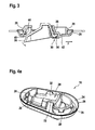
Figuren 4a bis 4c verschiedene Ansichten des Grundkörpers des Entwässerungsstopfens ausFigur 1 , und -
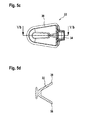
Figuren 5a bis 5d verschiedene Ansichten des Dichtungselements des Entwässerungsstopfens ausFigur 1 .
-
FIG. 1 a perspective view of a drainage plug according to the invention, -
FIG. 2 a sectional view through the drain plugFIG. 1 in a closed position, -
FIG. 3 a sectional view through the drain plugFIG. 1 in an open position, -
FIGS. 4a to 4c different views of the body of the drain plugFIG. 1 , and -
FIGS. 5a to 5d different views of the sealing element of the drain plugFIG. 1 ,
In
Der Entwässerungsstopfen 10 schließt den Durchbruch 12 während des Fahrbetriebs des Fahrzeugs, sodass ein Eindringen von Schmutz oder Feuchtigkeit in den Hohlraum 16 während der Fahrt verhindert werden kann. Bei Stillstand des Fahrzeugs öffnet sich der Entwässerungstopfen 10, so dass Flüssigkeit und Schmutz aus dem Hohlraum 16 abfließen können.The
Der Entwässerungsstopfen 10 hat einen Grundkörper 18, der in den Durchbruch 12 eingesetzt werden kann und eine Öffnung 20 aufweist. Des Weiteren hat der Entwässerungsstopfen 10 ein Dichtungselement 22, das, wie im Folgenden dargestellt wird, schwenkbar am Grundkörper 18 gelagert ist und zwischen einer Schließposition (
Wie in den
Der Grundkörper 18 weist des Weiteren eine Aufnahme 30 auf, die hier als Rastverbindung ausgebildet ist, und in die das Dichtungselement 22 eingeclipst werden kann. Am Rahmen 24 sind darüber hinaus Anlageflächen 32 vorgesehen, die das Dichtungselement 22 beim Bewegen in die Schließposition führen können.The
Wie in den
Wie in den
Bei einem stehenden Fahrzeug wird das Dichtungselement aufgrund der Schwerkraft bezüglich
In der Öffnungsposition ist das Dichtungselement 22 bezüglich
Im Fahrbetrieb wird das Dichtungselement 22 aufgrund der beim Fahren entstehenden Druckdifferenz zwischen Hohlraum 16 und Außenseite des Seitenschwellers 14 bezüglich der
In der Schließposition liegt das Dichtungselement 22 mit einem Rand 38 umlaufend an einem Dichtungsrand 40 des Grundkörpers 18 an und dichtet so die Öffnung 20 im Grundkörper 18 fluiddicht ab, so dass das Eindringen von Schmutz oder Wasser in den Hohlraum 16 verhindert ist.In the closed position, the sealing
In der Schließposition liegt das Dichtungselement 22 des Weiteren an den Anlageflächen 32 des Grundkörpers 18 an. Diese stabilisieren das Dichtungselement 22, sodass keine Undichtigkeiten aufgrund einer Verformung des Dichtungselements 22 entstehen können. Zudem erfolgt beim Verschwenken in die Schließposition automatisch eine Zentrierung des Dichtungselements 22.In the closed position, the sealing
Am Grundkörper 18 ist des Weiteren ein Windabweiser 42 vorgesehen, der in einer Fahrtrichtung F vor der Öffnung 20 und somit vor dem Dichtungselement 22 angeordnet ist.On the
Der Windabweiser 42 lenkt den Luftstrom während der Fahrt zusätzlich so ab, dass das Dichtungselement 22 zusätzlich in die Schließposition gedrängt wird und Wasser bzw. Schmutz von der Öffnung 20 bzw. dem Dichtungselement 22 weg abgelenkt werden, sodass eine Verschmutzung der Öffnung 20 bzw. des Dichtungselements 22, die zu einer verringerten Abdichtung führen könnte, verhindert wird.The
Der Windabweiser 42 ist in der hier gezeigten Ausführungsform in Fahrtrichtung vor dem Dichtungselement 22 angeordnet, der Windabweiser 42 könnte aber auch an einer anderen Position des Grundkörpers 18 angeordnet sein. Es ist lediglich sicherzustellen, dass dieser Schmutz und Wasser von der Öffnung 20 bzw. dem Dichtungselement 22 weglenkt.The
Claims (8)
Applications Claiming Priority (1)
| Application Number | Priority Date | Filing Date | Title |
|---|---|---|---|
| DE102012016250.2A DE102012016250B4 (en) | 2012-08-16 | 2012-08-16 | drain plug |
Publications (3)
| Publication Number | Publication Date |
|---|---|
| EP2698306A2 true EP2698306A2 (en) | 2014-02-19 |
| EP2698306A3 EP2698306A3 (en) | 2014-11-05 |
| EP2698306B1 EP2698306B1 (en) | 2016-12-21 |
Family
ID=48998416
Family Applications (1)
| Application Number | Title | Priority Date | Filing Date |
|---|---|---|---|
| EP13179626.0A Active EP2698306B1 (en) | 2012-08-16 | 2013-08-07 | Drainage plug |
Country Status (7)
| Country | Link |
|---|---|
| US (1) | US9254795B2 (en) |
| EP (1) | EP2698306B1 (en) |
| KR (1) | KR102093519B1 (en) |
| CN (1) | CN103587590B (en) |
| BR (1) | BR102013020750A2 (en) |
| DE (1) | DE102012016250B4 (en) |
| ES (1) | ES2619330T3 (en) |
Cited By (1)
| Publication number | Priority date | Publication date | Assignee | Title |
|---|---|---|---|---|
| FR3037306A1 (en) * | 2015-06-09 | 2016-12-16 | Peugeot Citroen Automobiles Sa | DEVICE FOR SEALING A DEFINED OPENING IN A FLOOR OF A VEHICLE, WITH A CAVITY OF HOUSING |
Families Citing this family (4)
| Publication number | Priority date | Publication date | Assignee | Title |
|---|---|---|---|---|
| DE102015106181B3 (en) * | 2015-04-22 | 2016-05-12 | Vorwerk Autotec Gmbh & Co.Kg | Drain device for removing liquid from a water tank of a motor vehicle |
| CN111746428B (en) * | 2020-07-08 | 2022-04-01 | 东风柳州汽车有限公司 | Drainage mechanism for side door of automobile |
| DE102022101568A1 (en) | 2022-01-24 | 2023-07-27 | Dr. Ing. H.C. F. Porsche Aktiengesellschaft | Protective cover for a chassis component of a motor vehicle |
| DE202022100510U1 (en) * | 2022-01-28 | 2022-03-09 | Weber Fibertech Gmbh | locking valve |
Citations (1)
| Publication number | Priority date | Publication date | Assignee | Title |
|---|---|---|---|---|
| DE102007026543A1 (en) | 2007-06-08 | 2008-12-11 | Daimler Ag | Drainage plug for a motor vehicle has a valve body with a drain path sealed by a body shutting off on one side to be inserted into an opening in a bodywork part |
Family Cites Families (11)
| Publication number | Priority date | Publication date | Assignee | Title |
|---|---|---|---|---|
| US4597112A (en) * | 1985-05-08 | 1986-07-01 | Casper Cuschera | Spring sealed drain fitting |
| FR2735189B1 (en) * | 1995-06-09 | 1997-09-05 | Peugeot | DEVICE FOR SEALING HOLES IN ANY PARTS |
| DE29711482U1 (en) * | 1997-07-01 | 1997-09-11 | United Carr Gmbh Trw | Plastic cover |
| DE19846498C2 (en) * | 1998-10-09 | 2000-10-19 | Heinz Brunner | Fuel cap |
| DE10012754A1 (en) * | 2000-03-16 | 2001-09-20 | Volkswagen Ag | Unit for hermetic closure of an opening comprises a sealing element which covers the opening rim and consists of a foam material, or is a combination of a carrier layer and a foam layer |
| TWM244854U (en) * | 2000-09-27 | 2004-10-01 | Nippon Oxygen Co Ltd | Cork for soft drink container |
| DE102006014963A1 (en) * | 2006-03-31 | 2007-10-04 | Dr.Ing.H.C. F. Porsche Ag | Sealing unit for a hollow profile of a vehicle body |
| DE102007048933A1 (en) * | 2007-10-12 | 2009-04-16 | Daimler Ag | Arrangement for plug in lacquer drain hole of vehicle body, has plug section formed as ring with central opening, and cover fixed on upper end of plug section, where central opening is closed by cover |
| DE102010055637B4 (en) * | 2010-12-22 | 2019-04-18 | Volkswagen Ag | Water drain valve |
| CN202358191U (en) * | 2011-12-05 | 2012-08-01 | 东风汽车股份有限公司 | Sealed rubber hole cover for vehicle body |
| CN102537431A (en) * | 2012-02-27 | 2012-07-04 | 无锡富尔金属制品有限公司 | Water draining check valve |
-
2012
- 2012-08-16 DE DE102012016250.2A patent/DE102012016250B4/en not_active Expired - Fee Related
-
2013
- 2013-08-07 ES ES13179626.0T patent/ES2619330T3/en active Active
- 2013-08-07 US US13/961,010 patent/US9254795B2/en not_active Expired - Fee Related
- 2013-08-07 EP EP13179626.0A patent/EP2698306B1/en active Active
- 2013-08-13 KR KR1020130095784A patent/KR102093519B1/en active IP Right Grant
- 2013-08-14 BR BR102013020750A patent/BR102013020750A2/en not_active Application Discontinuation
- 2013-08-16 CN CN201310357279.4A patent/CN103587590B/en active Active
Patent Citations (1)
| Publication number | Priority date | Publication date | Assignee | Title |
|---|---|---|---|---|
| DE102007026543A1 (en) | 2007-06-08 | 2008-12-11 | Daimler Ag | Drainage plug for a motor vehicle has a valve body with a drain path sealed by a body shutting off on one side to be inserted into an opening in a bodywork part |
Cited By (1)
| Publication number | Priority date | Publication date | Assignee | Title |
|---|---|---|---|---|
| FR3037306A1 (en) * | 2015-06-09 | 2016-12-16 | Peugeot Citroen Automobiles Sa | DEVICE FOR SEALING A DEFINED OPENING IN A FLOOR OF A VEHICLE, WITH A CAVITY OF HOUSING |
Also Published As
| Publication number | Publication date |
|---|---|
| CN103587590A (en) | 2014-02-19 |
| KR102093519B1 (en) | 2020-03-25 |
| EP2698306A3 (en) | 2014-11-05 |
| BR102013020750A2 (en) | 2016-03-01 |
| US9254795B2 (en) | 2016-02-09 |
| EP2698306B1 (en) | 2016-12-21 |
| US20140048554A1 (en) | 2014-02-20 |
| DE102012016250B4 (en) | 2015-10-08 |
| KR20140023217A (en) | 2014-02-26 |
| CN103587590B (en) | 2017-06-23 |
| ES2619330T3 (en) | 2017-06-26 |
| DE102012016250A1 (en) | 2014-02-20 |
Similar Documents
| Publication | Publication Date | Title |
|---|---|---|
| EP2698306B1 (en) | Drainage plug | |
| EP2646277B1 (en) | Charging interface for an electric vehicle | |
| DE102007031850B4 (en) | Drive device | |
| EP2641285B1 (en) | Energy storage for a motor vehicle with a locking device for condensate drainage | |
| EP3065964B1 (en) | Flap module | |
| DE112011102288T5 (en) | Valve control device | |
| DE202016100115U1 (en) | Door sill system for a front door, a shop door or the like | |
| DE202017106646U1 (en) | Automotive door assembly with water management element on window subassembly | |
| DE102017127564A1 (en) | Bleed valve for a vehicle | |
| DE202017100715U1 (en) | Lidless nozzle end for a fuel filler neck and fuel filler neck with a capless closure | |
| WO2018033175A1 (en) | Motor vehicle lock | |
| WO2016166275A1 (en) | Windshield cover arrangement for a motor vehicle | |
| DE102018121395A1 (en) | End rib arrangement for a buoyancy aid device of an aircraft with noise reduction | |
| DE19850378C1 (en) | Sealing bellows with support component locates on one hand on link pin and on other hand on link housing movably accommodating link pin on all sides | |
| DE102016217919A1 (en) | Ventilation and / or ventilation device for a housing, in particular for the transmission housing of a motor vehicle | |
| DE202008006050U1 (en) | sealing arrangement | |
| DE202006001144U1 (en) | Oil pan, in particular for an internal combustion engine | |
| DE102012010079A1 (en) | Coupling device for coupling a dust filter bag with an inlet device of a vacuum cleaner | |
| DE102013003739A1 (en) | Device for covering a pipe end | |
| DE102012100198B4 (en) | One-piece plastic molded part with a flap free of play in a closed position and its arrangement in the engine compartment of a motor vehicle | |
| DE10348444B4 (en) | Pivoting cover part in a vehicle | |
| DE102013202430A1 (en) | container lid | |
| DE102012013731A1 (en) | Water drain valve for the water tank of a motor vehicle | |
| DE102017111834A1 (en) | Gripping and clamping device | |
| EP3762640B1 (en) | Venting valve and hybrid module |
Legal Events
| Date | Code | Title | Description |
|---|---|---|---|
| AK | Designated contracting states |
Kind code of ref document: A2 Designated state(s): AL AT BE BG CH CY CZ DE DK EE ES FI FR GB GR HR HU IE IS IT LI LT LU LV MC MK MT NL NO PL PT RO RS SE SI SK SM TR |
|
| AX | Request for extension of the european patent |
Extension state: BA ME |
|
| PUAI | Public reference made under article 153(3) epc to a published international application that has entered the european phase |
Free format text: ORIGINAL CODE: 0009012 |
|
| PUAL | Search report despatched |
Free format text: ORIGINAL CODE: 0009013 |
|
| AK | Designated contracting states |
Kind code of ref document: A3 Designated state(s): AL AT BE BG CH CY CZ DE DK EE ES FI FR GB GR HR HU IE IS IT LI LT LU LV MC MK MT NL NO PL PT RO RS SE SI SK SM TR |
|
| AX | Request for extension of the european patent |
Extension state: BA ME |
|
| RIC1 | Information provided on ipc code assigned before grant |
Ipc: F16K 15/14 20060101ALI20141001BHEP Ipc: B62D 25/24 20060101AFI20141001BHEP |
|
| 17P | Request for examination filed |
Effective date: 20141217 |
|
| RBV | Designated contracting states (corrected) |
Designated state(s): AL AT BE BG CH CY CZ DE DK EE ES FI FR GB GR HR HU IE IS IT LI LT LU LV MC MK MT NL NO PL PT RO RS SE SI SK SM TR |
|
| GRAP | Despatch of communication of intention to grant a patent |
Free format text: ORIGINAL CODE: EPIDOSNIGR1 |
|
| INTG | Intention to grant announced |
Effective date: 20160826 |
|
| GRAS | Grant fee paid |
Free format text: ORIGINAL CODE: EPIDOSNIGR3 |
|
| GRAA | (expected) grant |
Free format text: ORIGINAL CODE: 0009210 |
|
| AK | Designated contracting states |
Kind code of ref document: B1 Designated state(s): AL AT BE BG CH CY CZ DE DK EE ES FI FR GB GR HR HU IE IS IT LI LT LU LV MC MK MT NL NO PL PT RO RS SE SI SK SM TR |
|
| REG | Reference to a national code |
Ref country code: GB Ref legal event code: FG4D Free format text: NOT ENGLISH |
|
| REG | Reference to a national code |
Ref country code: CH Ref legal event code: EP |
|
| REG | Reference to a national code |
Ref country code: IE Ref legal event code: FG4D Free format text: LANGUAGE OF EP DOCUMENT: GERMAN |
|
| REG | Reference to a national code |
Ref country code: AT Ref legal event code: REF Ref document number: 855199 Country of ref document: AT Kind code of ref document: T Effective date: 20170115 |
|
| REG | Reference to a national code |
Ref country code: DE Ref legal event code: R096 Ref document number: 502013005817 Country of ref document: DE |
|
| RAP2 | Party data changed (patent owner data changed or rights of a patent transferred) |
Owner name: ITW FASTENER PRODUCTS GMBH |
|
| PG25 | Lapsed in a contracting state [announced via postgrant information from national office to epo] |
Ref country code: LV Free format text: LAPSE BECAUSE OF FAILURE TO SUBMIT A TRANSLATION OF THE DESCRIPTION OR TO PAY THE FEE WITHIN THE PRESCRIBED TIME-LIMIT Effective date: 20161221 |
|
| REG | Reference to a national code |
Ref country code: LT Ref legal event code: MG4D |
|
| REG | Reference to a national code |
Ref country code: NL Ref legal event code: MP Effective date: 20161221 |
|
| PG25 | Lapsed in a contracting state [announced via postgrant information from national office to epo] |
Ref country code: NO Free format text: LAPSE BECAUSE OF FAILURE TO SUBMIT A TRANSLATION OF THE DESCRIPTION OR TO PAY THE FEE WITHIN THE PRESCRIBED TIME-LIMIT Effective date: 20170321 Ref country code: LT Free format text: LAPSE BECAUSE OF FAILURE TO SUBMIT A TRANSLATION OF THE DESCRIPTION OR TO PAY THE FEE WITHIN THE PRESCRIBED TIME-LIMIT Effective date: 20161221 Ref country code: GR Free format text: LAPSE BECAUSE OF FAILURE TO SUBMIT A TRANSLATION OF THE DESCRIPTION OR TO PAY THE FEE WITHIN THE PRESCRIBED TIME-LIMIT Effective date: 20170322 Ref country code: SE Free format text: LAPSE BECAUSE OF FAILURE TO SUBMIT A TRANSLATION OF THE DESCRIPTION OR TO PAY THE FEE WITHIN THE PRESCRIBED TIME-LIMIT Effective date: 20161221 |
|
| PG25 | Lapsed in a contracting state [announced via postgrant information from national office to epo] |
Ref country code: RS Free format text: LAPSE BECAUSE OF FAILURE TO SUBMIT A TRANSLATION OF THE DESCRIPTION OR TO PAY THE FEE WITHIN THE PRESCRIBED TIME-LIMIT Effective date: 20161221 Ref country code: FI Free format text: LAPSE BECAUSE OF FAILURE TO SUBMIT A TRANSLATION OF THE DESCRIPTION OR TO PAY THE FEE WITHIN THE PRESCRIBED TIME-LIMIT Effective date: 20161221 Ref country code: HR Free format text: LAPSE BECAUSE OF FAILURE TO SUBMIT A TRANSLATION OF THE DESCRIPTION OR TO PAY THE FEE WITHIN THE PRESCRIBED TIME-LIMIT Effective date: 20161221 |
|
| REG | Reference to a national code |
Ref country code: ES Ref legal event code: FG2A Ref document number: 2619330 Country of ref document: ES Kind code of ref document: T3 Effective date: 20170626 |
|
| RAP2 | Party data changed (patent owner data changed or rights of a patent transferred) |
Owner name: ILLINOIS TOOL WORKS INC. |
|
| PG25 | Lapsed in a contracting state [announced via postgrant information from national office to epo] |
Ref country code: NL Free format text: LAPSE BECAUSE OF FAILURE TO SUBMIT A TRANSLATION OF THE DESCRIPTION OR TO PAY THE FEE WITHIN THE PRESCRIBED TIME-LIMIT Effective date: 20161221 |
|
| PG25 | Lapsed in a contracting state [announced via postgrant information from national office to epo] |
Ref country code: RO Free format text: LAPSE BECAUSE OF FAILURE TO SUBMIT A TRANSLATION OF THE DESCRIPTION OR TO PAY THE FEE WITHIN THE PRESCRIBED TIME-LIMIT Effective date: 20161221 Ref country code: IS Free format text: LAPSE BECAUSE OF FAILURE TO SUBMIT A TRANSLATION OF THE DESCRIPTION OR TO PAY THE FEE WITHIN THE PRESCRIBED TIME-LIMIT Effective date: 20170421 Ref country code: CZ Free format text: LAPSE BECAUSE OF FAILURE TO SUBMIT A TRANSLATION OF THE DESCRIPTION OR TO PAY THE FEE WITHIN THE PRESCRIBED TIME-LIMIT Effective date: 20161221 Ref country code: EE Free format text: LAPSE BECAUSE OF FAILURE TO SUBMIT A TRANSLATION OF THE DESCRIPTION OR TO PAY THE FEE WITHIN THE PRESCRIBED TIME-LIMIT Effective date: 20161221 Ref country code: SK Free format text: LAPSE BECAUSE OF FAILURE TO SUBMIT A TRANSLATION OF THE DESCRIPTION OR TO PAY THE FEE WITHIN THE PRESCRIBED TIME-LIMIT Effective date: 20161221 |
|
| REG | Reference to a national code |
Ref country code: FR Ref legal event code: PLFP Year of fee payment: 5 |
|
| REG | Reference to a national code |
Ref country code: GB Ref legal event code: 732E Free format text: REGISTERED BETWEEN 20170803 AND 20170809 |
|
| PG25 | Lapsed in a contracting state [announced via postgrant information from national office to epo] |
Ref country code: BG Free format text: LAPSE BECAUSE OF FAILURE TO SUBMIT A TRANSLATION OF THE DESCRIPTION OR TO PAY THE FEE WITHIN THE PRESCRIBED TIME-LIMIT Effective date: 20170321 Ref country code: SM Free format text: LAPSE BECAUSE OF FAILURE TO SUBMIT A TRANSLATION OF THE DESCRIPTION OR TO PAY THE FEE WITHIN THE PRESCRIBED TIME-LIMIT Effective date: 20161221 Ref country code: PT Free format text: LAPSE BECAUSE OF FAILURE TO SUBMIT A TRANSLATION OF THE DESCRIPTION OR TO PAY THE FEE WITHIN THE PRESCRIBED TIME-LIMIT Effective date: 20170421 Ref country code: PL Free format text: LAPSE BECAUSE OF FAILURE TO SUBMIT A TRANSLATION OF THE DESCRIPTION OR TO PAY THE FEE WITHIN THE PRESCRIBED TIME-LIMIT Effective date: 20161221 |
|
| REG | Reference to a national code |
Ref country code: GB Ref legal event code: 732E Free format text: REGISTERED BETWEEN 20170810 AND 20170816 |
|
| REG | Reference to a national code |
Ref country code: DE Ref legal event code: R097 Ref document number: 502013005817 Country of ref document: DE |
|
| PLBE | No opposition filed within time limit |
Free format text: ORIGINAL CODE: 0009261 |
|
| STAA | Information on the status of an ep patent application or granted ep patent |
Free format text: STATUS: NO OPPOSITION FILED WITHIN TIME LIMIT |
|
| PGFP | Annual fee paid to national office [announced via postgrant information from national office to epo] |
Ref country code: ES Payment date: 20170901 Year of fee payment: 5 |
|
| 26N | No opposition filed |
Effective date: 20170922 |
|
| PG25 | Lapsed in a contracting state [announced via postgrant information from national office to epo] |
Ref country code: DK Free format text: LAPSE BECAUSE OF FAILURE TO SUBMIT A TRANSLATION OF THE DESCRIPTION OR TO PAY THE FEE WITHIN THE PRESCRIBED TIME-LIMIT Effective date: 20161221 |
|
| PG25 | Lapsed in a contracting state [announced via postgrant information from national office to epo] |
Ref country code: SI Free format text: LAPSE BECAUSE OF FAILURE TO SUBMIT A TRANSLATION OF THE DESCRIPTION OR TO PAY THE FEE WITHIN THE PRESCRIBED TIME-LIMIT Effective date: 20161221 |
|
| REG | Reference to a national code |
Ref country code: CH Ref legal event code: PL |
|
| PG25 | Lapsed in a contracting state [announced via postgrant information from national office to epo] |
Ref country code: MC Free format text: LAPSE BECAUSE OF FAILURE TO SUBMIT A TRANSLATION OF THE DESCRIPTION OR TO PAY THE FEE WITHIN THE PRESCRIBED TIME-LIMIT Effective date: 20161221 |
|
| PG25 | Lapsed in a contracting state [announced via postgrant information from national office to epo] |
Ref country code: CH Free format text: LAPSE BECAUSE OF NON-PAYMENT OF DUE FEES Effective date: 20170831 Ref country code: LI Free format text: LAPSE BECAUSE OF NON-PAYMENT OF DUE FEES Effective date: 20170831 |
|
| REG | Reference to a national code |
Ref country code: IE Ref legal event code: MM4A |
|
| REG | Reference to a national code |
Ref country code: BE Ref legal event code: MM Effective date: 20170831 |
|
| PG25 | Lapsed in a contracting state [announced via postgrant information from national office to epo] |
Ref country code: LU Free format text: LAPSE BECAUSE OF NON-PAYMENT OF DUE FEES Effective date: 20170807 |
|
| PG25 | Lapsed in a contracting state [announced via postgrant information from national office to epo] |
Ref country code: IE Free format text: LAPSE BECAUSE OF NON-PAYMENT OF DUE FEES Effective date: 20170807 |
|
| REG | Reference to a national code |
Ref country code: FR Ref legal event code: PLFP Year of fee payment: 6 |
|
| PG25 | Lapsed in a contracting state [announced via postgrant information from national office to epo] |
Ref country code: BE Free format text: LAPSE BECAUSE OF NON-PAYMENT OF DUE FEES Effective date: 20170831 |
|
| PG25 | Lapsed in a contracting state [announced via postgrant information from national office to epo] |
Ref country code: MT Free format text: LAPSE BECAUSE OF FAILURE TO SUBMIT A TRANSLATION OF THE DESCRIPTION OR TO PAY THE FEE WITHIN THE PRESCRIBED TIME-LIMIT Effective date: 20161221 |
|
| PGFP | Annual fee paid to national office [announced via postgrant information from national office to epo] |
Ref country code: DE Payment date: 20180723 Year of fee payment: 12 |
|
| PGFP | Annual fee paid to national office [announced via postgrant information from national office to epo] |
Ref country code: GB Payment date: 20180828 Year of fee payment: 6 |
|
| PG25 | Lapsed in a contracting state [announced via postgrant information from national office to epo] |
Ref country code: HU Free format text: LAPSE BECAUSE OF FAILURE TO SUBMIT A TRANSLATION OF THE DESCRIPTION OR TO PAY THE FEE WITHIN THE PRESCRIBED TIME-LIMIT; INVALID AB INITIO Effective date: 20130807 |
|
| REG | Reference to a national code |
Ref country code: ES Ref legal event code: FD2A Effective date: 20190918 |
|
| REG | Reference to a national code |
Ref country code: AT Ref legal event code: MM01 Ref document number: 855199 Country of ref document: AT Kind code of ref document: T Effective date: 20180807 |
|
| PG25 | Lapsed in a contracting state [announced via postgrant information from national office to epo] |
Ref country code: CY Free format text: LAPSE BECAUSE OF NON-PAYMENT OF DUE FEES Effective date: 20161221 Ref country code: ES Free format text: LAPSE BECAUSE OF NON-PAYMENT OF DUE FEES Effective date: 20180808 |
|
| PG25 | Lapsed in a contracting state [announced via postgrant information from national office to epo] |
Ref country code: MK Free format text: LAPSE BECAUSE OF FAILURE TO SUBMIT A TRANSLATION OF THE DESCRIPTION OR TO PAY THE FEE WITHIN THE PRESCRIBED TIME-LIMIT Effective date: 20161221 |
|
| PG25 | Lapsed in a contracting state [announced via postgrant information from national office to epo] |
Ref country code: AT Free format text: LAPSE BECAUSE OF NON-PAYMENT OF DUE FEES Effective date: 20180807 |
|
| PG25 | Lapsed in a contracting state [announced via postgrant information from national office to epo] |
Ref country code: TR Free format text: LAPSE BECAUSE OF FAILURE TO SUBMIT A TRANSLATION OF THE DESCRIPTION OR TO PAY THE FEE WITHIN THE PRESCRIBED TIME-LIMIT Effective date: 20161221 |
|
| GBPC | Gb: european patent ceased through non-payment of renewal fee |
Effective date: 20190807 |
|
| PG25 | Lapsed in a contracting state [announced via postgrant information from national office to epo] |
Ref country code: AL Free format text: LAPSE BECAUSE OF FAILURE TO SUBMIT A TRANSLATION OF THE DESCRIPTION OR TO PAY THE FEE WITHIN THE PRESCRIBED TIME-LIMIT Effective date: 20161221 |
|
| PG25 | Lapsed in a contracting state [announced via postgrant information from national office to epo] |
Ref country code: IT Free format text: LAPSE BECAUSE OF NON-PAYMENT OF DUE FEES Effective date: 20190807 Ref country code: GB Free format text: LAPSE BECAUSE OF NON-PAYMENT OF DUE FEES Effective date: 20190807 |
|
| REG | Reference to a national code |
Ref country code: DE Ref legal event code: R119 Ref document number: 502013005817 Country of ref document: DE |
|
| PG25 | Lapsed in a contracting state [announced via postgrant information from national office to epo] |
Ref country code: DE Free format text: LAPSE BECAUSE OF NON-PAYMENT OF DUE FEES Effective date: 20210302 |
|
| P01 | Opt-out of the competence of the unified patent court (upc) registered |
Effective date: 20230606 |
|
| PGFP | Annual fee paid to national office [announced via postgrant information from national office to epo] |
Ref country code: FR Payment date: 20230825 Year of fee payment: 11 |