EP2698289A2 - Method for preventing theft of an electric vehicle and an electric vehicle applying the same - Google Patents
Method for preventing theft of an electric vehicle and an electric vehicle applying the same Download PDFInfo
- Publication number
- EP2698289A2 EP2698289A2 EP13166668.7A EP13166668A EP2698289A2 EP 2698289 A2 EP2698289 A2 EP 2698289A2 EP 13166668 A EP13166668 A EP 13166668A EP 2698289 A2 EP2698289 A2 EP 2698289A2
- Authority
- EP
- European Patent Office
- Prior art keywords
- rotation
- drive wheel
- motor
- detector
- electric vehicle
- Prior art date
- Legal status (The legal status is an assumption and is not a legal conclusion. Google has not performed a legal analysis and makes no representation as to the accuracy of the status listed.)
- Withdrawn
Links
- 238000000034 method Methods 0.000 title claims abstract description 22
- 230000005611 electricity Effects 0.000 claims description 8
- 238000010586 diagram Methods 0.000 description 3
- 238000001514 detection method Methods 0.000 description 1
- 230000007613 environmental effect Effects 0.000 description 1
- 238000004519 manufacturing process Methods 0.000 description 1
Images


Classifications
-
- B—PERFORMING OPERATIONS; TRANSPORTING
- B62—LAND VEHICLES FOR TRAVELLING OTHERWISE THAN ON RAILS
- B62H—CYCLE STANDS; SUPPORTS OR HOLDERS FOR PARKING OR STORING CYCLES; APPLIANCES PREVENTING OR INDICATING UNAUTHORIZED USE OR THEFT OF CYCLES; LOCKS INTEGRAL WITH CYCLES; DEVICES FOR LEARNING TO RIDE CYCLES
- B62H5/00—Appliances preventing or indicating unauthorised use or theft of cycles; Locks integral with cycles
- B62H5/08—Appliances preventing or indicating unauthorised use or theft of cycles; Locks integral with cycles preventing the drive
-
- B—PERFORMING OPERATIONS; TRANSPORTING
- B60—VEHICLES IN GENERAL
- B60R—VEHICLES, VEHICLE FITTINGS, OR VEHICLE PARTS, NOT OTHERWISE PROVIDED FOR
- B60R25/00—Fittings or systems for preventing or indicating unauthorised use or theft of vehicles
- B60R25/01—Fittings or systems for preventing or indicating unauthorised use or theft of vehicles operating on vehicle systems or fittings, e.g. on doors, seats or windscreens
- B60R25/08—Fittings or systems for preventing or indicating unauthorised use or theft of vehicles operating on vehicle systems or fittings, e.g. on doors, seats or windscreens operating on brakes or brake systems
-
- B—PERFORMING OPERATIONS; TRANSPORTING
- B62—LAND VEHICLES FOR TRAVELLING OTHERWISE THAN ON RAILS
- B62H—CYCLE STANDS; SUPPORTS OR HOLDERS FOR PARKING OR STORING CYCLES; APPLIANCES PREVENTING OR INDICATING UNAUTHORIZED USE OR THEFT OF CYCLES; LOCKS INTEGRAL WITH CYCLES; DEVICES FOR LEARNING TO RIDE CYCLES
- B62H5/00—Appliances preventing or indicating unauthorised use or theft of cycles; Locks integral with cycles
- B62H5/14—Appliances preventing or indicating unauthorised use or theft of cycles; Locks integral with cycles preventing wheel rotation
- B62H5/18—Appliances preventing or indicating unauthorised use or theft of cycles; Locks integral with cycles preventing wheel rotation acting on a braking device
Definitions
- the present invention relates to a method for preventing theft of an electric vehicle and an electric vehicle applying the method.
- a conventional vehicle 1 includes a vehicle body 11, a front wheel 12 and a rear wheel 13 spacedly apart from each other and rotatably disposed on the vehicle body 11, a motor 14 for driving the rear wheel 13, a power supply 15 for providing the needed electric power to the motor 14, and a controller 16 electrically connected to the motor 14 and the power supply 15.
- the controller 16 controls the rotation speed of the motor 14 to control the movement speed of the electric vehicle 1.
- an object of the present invention is to provide a method for preventing theft of an electric vehicle, and an electric vehicle applying the method.
- an electric vehicle including a main switch, a switch detector for detecting a switch state of the main switch, an electric power source controlled by the main switch, a motor for converting electricity from the electric power source into a mechanical power output, a drive wheel driven by the mechanical power output of the motor, a rotation detector for detecting rotation of the drive wheel, a locking mechanism operable to lock the drive wheel from rotation, and a controller coupled to the switch detector, the electric power source, the motor, the rotation detector and the locking mechanism.
- the method for preventing theft of the electric vehicle comprises the steps of:
- the electric vehicle 2 includes a main switch 21, a switch detector 22 for detecting a switch state of the main switch 21, an electric power source 23 controlled by the main switch 21, a motor 24 for converting electricity from the electric power source 23 into a mechanical power output, a drive wheel 25 driven by the mechanical power output of the motor 24, a rotation detector 26 for detecting rotation of the drive wheel 25, a locking mechanism 27 operable to lock the drive wheel 25 from rotation, and a controller 28 (such as a central processing unit) electrically coupled to the switch detector 22, the electric power source 23, the motor 24, the rotation detector 26 and the locking mechanism 27.
- the controller 28 also stores a program for implementing the method for preventing theft of an electric vehicle.
- the electric power source 23 is a battery
- the drive wheel 25 is a rear wheel of the electric vehicle 2
- the rotation detector 26 is a Hall sensor that the motor 24 uses for rotation detection
- the locking mechanism 27 includes a plurality of power transistors electrically connected to the motor 24 and the electric power source 23.
- the rotation detector 26 can also be a voltage comparator or a voltage switch that detects the back electromotive force produced by the rotation in the motor 24.
- the locking mechanism 27 can also be a brake that brakes the drive wheel 25.
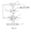
- the method for preventing theft of an electric vehicle includes step (A) : detecting the state of the main switch 21. If the main switch 21 is in an OFF state, the controller 28 configures the electric power source 23 to enter a power saving mode, and the controller 28 performs step (B). In the power saving mode, the electric power source 23 only provides power to the rotation detector 26 and the controller 28, effectively minimizing power consumption. If the main switch 21 is in an ON state, it represents that the electric vehicle 2 is actuated by a vehicle owner using a vehicle key, and is not being stolen. Therefore, the electric vehicle 2 enters a normal driving mode, and the motor 24 operates using the electricity supplied from the electric power source 23.
- Step (B) utilizes the rotation detector 26 to detect the rotation of the drive wheel 25. If the drive wheel 25 rotates but the main switch 21 is in an OFF state, the electric vehicle 2 is either being moved or stolen. At this moment, the rotation detector 26 sends a signal to wake up the controller 28 in the power saving mode and step (C) is then performed. If the drive wheel 25 is not rotating, then the electric vehicle 2 remains in the power saving mode and therefore step (A) is performed for the switch detector 22 to continuously detect for actuation of the main switch 21.
- Step (C) configures the controller 28 to count if a time period of the rotation of the drive wheel 25 reaches a preset time period. If the counted time period reaches the preset time period, the electric vehicle 2 is moved a certain distance while the main switch 21 is not actuated. Possibly, the electric vehicle 2 is being stolen, and step (D) is performed next. If the counted time period does not reach the preset time period, the drive wheel 25 of the electric vehicle 2 did not rotate much. Possibly, the electric vehicle 2 is only moved a small distance and not being stolen, and therefore step (A) is performed next. In this preferred embodiment, the preset time period is one minute but should not be limited thereto.
- the controller 28 counts the time period of rotation of the drive wheel 25 from the duration of the detected signal from the rotation detector 26.
- Step (D) configures the controller 28 to control the locking mechanism 27 to brake the drive wheel 25, preventing the thief from pushing the electric vehicle 2 further.
- the controller 28 turns on two power transistors to brake the motor 24 in order to brake the drive wheel 25.
- the method for preventing theft of an electric vehicle 2 configures, in step (B), the rotation detector 26 to detect the rotation of the drive wheel 25, configures, in step (C), the controller 28 to determine whether the duration of the detected signal from the rotation detector 26 reaches the preset time period, and configures, in step (D), the controller 28 to control the locking mechanism 27 to brake the motor 24 in order to brake the drive wheel 25.
- This method provides an internal anti-theft mechanism which is difficult for a thief to tamper with.
- a second preferred embodiment of the method of this invention is similar to the first preferred embodiment, with the differences being: the electric vehicle 2 further includes an auxiliary electric power source 29 electrically connected to the motor 24, the controller 28, and the rotation detector 26.
- the auxiliary electric power source 29 is charged by the back electromotive force of the motor 24, and provides electricity to the controller 28 and the rotation detector 26 when the electric power source 23 is unable to provide electricity.
- the auxiliary electric power source 29 provides enough power for the controller 28 and the rotation detector 26 to maintain the anti-theft operation of the electric vehicle 2.
- the method for preventing theft of an electric vehicle 2 configures, in step (B), the rotation detector 26 to detect the rotation of the drive wheel 25, configures, in step (C), the controller 28 to determine whether the duration of the detected signal from the rotation detector 26 reaches the preset time period, and configures, in step (D), the controller 28 to control the locking mechanism 27 to brake the motor 24 in order to brake the drive wheel 25.
- This method provides an internal anti-theft mechanism which is difficult for a thief to tamper with.
- the components used in such electric vehicle 2 are common in any electric vehicle, and therefore the manufacturing cost can be effectively lowered.
Landscapes
- Engineering & Computer Science (AREA)
- Mechanical Engineering (AREA)
- Electric Propulsion And Braking For Vehicles (AREA)
- Burglar Alarm Systems (AREA)
Abstract
Description
- The present invention relates to a method for preventing theft of an electric vehicle and an electric vehicle applying the method.
- In recent years, due to environmental protection becoming an important issue, people started replacing gasoline motor vehicles with electric vehicles.
- Referring to
Figure 1 , aconventional vehicle 1 includes avehicle body 11, afront wheel 12 and arear wheel 13 spacedly apart from each other and rotatably disposed on thevehicle body 11, amotor 14 for driving therear wheel 13, apower supply 15 for providing the needed electric power to themotor 14, and acontroller 16 electrically connected to themotor 14 and thepower supply 15. Thecontroller 16 controls the rotation speed of themotor 14 to control the movement speed of theelectric vehicle 1. - However, theft is common for both electric vehicles and gasoline vehicles, and therefore the users of such vehicles often require appropriate locking devices to lock the parked vehicles in order to prevent theft of the vehicles.
- Nevertheless, purchasing the locking devices requires extra expenditure and the locking devices may be intentionally damaged as they are mostly exposed on the exterior of the vehicles. Such locking devices also affect the vehicle aesthetically.
- Therefore, an object of the present invention is to provide a method for preventing theft of an electric vehicle, and an electric vehicle applying the method.
- According to the present invention, there is provided an electric vehicle including a main switch, a switch detector for detecting a switch state of the main switch, an electric power source controlled by the main switch, a motor for converting electricity from the electric power source into a mechanical power output, a drive wheel driven by the mechanical power output of the motor, a rotation detector for detecting rotation of the drive wheel, a locking mechanism operable to lock the drive wheel from rotation, and a controller coupled to the switch detector, the electric power source, the motor, the rotation detector and the locking mechanism.
- The method for preventing theft of the electric vehicle comprises the steps of:
- a) when the switch detector detects that the state of the main switch is an OFF state, and when the rotation detector detects that the drive wheel is rotating, configuring the controller to count a time period of rotation of the drive wheel; and
- b) configuring the controller to enable the locking mechanism for locking the drive wheel from rotation when the time period counted by the controller reaches a preset time period.
- Other features and advantages of the present invention will become apparent in the following detailed description of the preferred embodiments with reference to the accompanying drawings, of which:
-
Figure 1 is a schematic diagram of a conventional vehicle; -
Figure 2 is a schematic block diagram of the first preferred embodiment of an electric vehicle according to the present invention; -
Figure 3 is a flow chart of the method performed by the first preferred embodiment of an electric vehicle according to the present invention; and -
Figure 4 is a schematic block diagram of the second preferred embodiment of an electric vehicle according to the present invention. - Referring to
Figures 2 and3 , the first preferred embodiment of the method for preventing theft of an electric vehicle is applied to anelectric vehicle 2. Theelectric vehicle 2 includes amain switch 21, aswitch detector 22 for detecting a switch state of themain switch 21, anelectric power source 23 controlled by themain switch 21, amotor 24 for converting electricity from theelectric power source 23 into a mechanical power output, adrive wheel 25 driven by the mechanical power output of themotor 24, arotation detector 26 for detecting rotation of thedrive wheel 25, alocking mechanism 27 operable to lock thedrive wheel 25 from rotation, and a controller 28 (such as a central processing unit) electrically coupled to theswitch detector 22, theelectric power source 23, themotor 24, therotation detector 26 and thelocking mechanism 27. Thecontroller 28 also stores a program for implementing the method for preventing theft of an electric vehicle. - In this preferred embodiment, the
electric power source 23 is a battery, thedrive wheel 25 is a rear wheel of theelectric vehicle 2, therotation detector 26 is a Hall sensor that themotor 24 uses for rotation detection, and thelocking mechanism 27 includes a plurality of power transistors electrically connected to themotor 24 and theelectric power source 23. - When external forces are applied on the
drive wheel 25, themotor 24 can be reversely driven, causing themotor 24 to produce back electromotive force. Therefore, therotation detector 26 can also be a voltage comparator or a voltage switch that detects the back electromotive force produced by the rotation in themotor 24. Thelocking mechanism 27 can also be a brake that brakes thedrive wheel 25. - The method for preventing theft of an electric vehicle includes step (A) : detecting the state of the
main switch 21. If themain switch 21 is in an OFF state, thecontroller 28 configures theelectric power source 23 to enter a power saving mode, and thecontroller 28 performs step (B). In the power saving mode, theelectric power source 23 only provides power to therotation detector 26 and thecontroller 28, effectively minimizing power consumption. If themain switch 21 is in an ON state, it represents that theelectric vehicle 2 is actuated by a vehicle owner using a vehicle key, and is not being stolen. Therefore, theelectric vehicle 2 enters a normal driving mode, and themotor 24 operates using the electricity supplied from theelectric power source 23. - Step (B) utilizes the
rotation detector 26 to detect the rotation of thedrive wheel 25. If thedrive wheel 25 rotates but themain switch 21 is in an OFF state, theelectric vehicle 2 is either being moved or stolen. At this moment, therotation detector 26 sends a signal to wake up thecontroller 28 in the power saving mode and step (C) is then performed. If thedrive wheel 25 is not rotating, then theelectric vehicle 2 remains in the power saving mode and therefore step (A) is performed for theswitch detector 22 to continuously detect for actuation of themain switch 21. - Step (C) configures the
controller 28 to count if a time period of the rotation of thedrive wheel 25 reaches a preset time period. If the counted time period reaches the preset time period, theelectric vehicle 2 is moved a certain distance while themain switch 21 is not actuated. Possibly, theelectric vehicle 2 is being stolen, and step (D) is performed next. If the counted time period does not reach the preset time period, thedrive wheel 25 of theelectric vehicle 2 did not rotate much. Possibly, theelectric vehicle 2 is only moved a small distance and not being stolen, and therefore step (A) is performed next. In this preferred embodiment, the preset time period is one minute but should not be limited thereto. - In this preferred embodiment, the
controller 28 counts the time period of rotation of thedrive wheel 25 from the duration of the detected signal from therotation detector 26. - Step (D) configures the
controller 28 to control thelocking mechanism 27 to brake thedrive wheel 25, preventing the thief from pushing theelectric vehicle 2 further. In this preferred embodiment, thecontroller 28 turns on two power transistors to brake themotor 24 in order to brake thedrive wheel 25. - In this preferred embodiment, the method for preventing theft of an
electric vehicle 2 configures, in step (B), therotation detector 26 to detect the rotation of thedrive wheel 25, configures, in step (C), thecontroller 28 to determine whether the duration of the detected signal from therotation detector 26 reaches the preset time period, and configures, in step (D), thecontroller 28 to control thelocking mechanism 27 to brake themotor 24 in order to brake thedrive wheel 25. This method provides an internal anti-theft mechanism which is difficult for a thief to tamper with. - Referring to
Figure 4 , a second preferred embodiment of the method of this invention is similar to the first preferred embodiment, with the differences being: theelectric vehicle 2 further includes an auxiliaryelectric power source 29 electrically connected to themotor 24, thecontroller 28, and therotation detector 26. The auxiliaryelectric power source 29 is charged by the back electromotive force of themotor 24, and provides electricity to thecontroller 28 and therotation detector 26 when theelectric power source 23 is unable to provide electricity. - Therefore, in the event that the
electric power source 23 is depleted or stolen, the auxiliaryelectric power source 29 provides enough power for thecontroller 28 and therotation detector 26 to maintain the anti-theft operation of theelectric vehicle 2. - In summary, the method for preventing theft of an
electric vehicle 2 configures, in step (B), therotation detector 26 to detect the rotation of thedrive wheel 25, configures, in step (C), thecontroller 28 to determine whether the duration of the detected signal from therotation detector 26 reaches the preset time period, and configures, in step (D), thecontroller 28 to control thelocking mechanism 27 to brake themotor 24 in order to brake thedrive wheel 25. This method provides an internal anti-theft mechanism which is difficult for a thief to tamper with. Moreover, the components used in suchelectric vehicle 2 are common in any electric vehicle, and therefore the manufacturing cost can be effectively lowered.
Claims (11)
- A method for preventing theft of an electric vehicle (2), the electric vehicle (2) including a main switch (21), a switch detector (22) for detecting a switch state of the main switch (21), an electric power source (23) controlled by the main switch (21), a motor (24) for converting electricity from the electric power source (23) into a mechanical power output, a drive wheel (25) driven by the mechanical power output of the motor (24), a rotation detector (26) for detecting rotation of the drive wheel (25), a locking mechanism (27) operable to lock the drive wheel (25) from rotation, and a controller (28) coupled to the switch detector (22), the electric power source (23), the motor (24), the rotation detector (26) and the locking mechanism (27), the method characterized by:a) when the switch detector (22) detects that the state of the main switch (21) is an OFF state, and when the rotation detector (26) detects that the drive wheel (25) is rotating, configuring the controller (28) to count a time period of rotation of the drive wheel (25); andb) configuring the controller (28) to enable the locking mechanism (27) for locking the drive wheel (25) from rotation when the time period counted by the controller (28) reaches a preset time period.
- The method as claimed in Claim 1, characterized in that the rotation detector (26) detects rotation of the drive wheel (25) by detecting rotation of the motor (24).
- The method as claimed in Claim 1, characterized in that the rotation detector (26) detects rotation of the drive wheel (25) by detecting back electromotive force generated by the motor (24).
- The method as claimed in any one of Claims 1 to 3, characterized in that the locking mechanism (27) is operable to lock rotation of the drive wheel (25) by locking rotation of the motor (24).
- The method as claimed in any one of Claims 1 to 3, characterized in that the locking mechanism (27) is operable to lock rotation of the drive wheel (25) by applying a braking force thereto.
- An electric vehicle (2) comprising:a main switch (21);a switch detector (22) for detecting a switch state of said main switch (21);an electric power source (23) controlled by said main switch (21);a motor (24) for converting electricity from said electric power source (23) into a mechanical power output;a drive wheel (25) driven by said mechanical power output of said motor (24);a rotation detector (26) for detecting rotation of said drive wheel (25);a locking mechanism (27) operable to lock said drive wheel (25) from rotation; anda controller (28) coupled to said switch detector (22), said electric power source (23), said motor (24), said rotation detector (26) and said locking mechanism (27);characterized in that when said switch detector (22) detects that said state of said main switch (21) is an OFF state, and when said rotation detector (26) detects that said drive wheel (25) is rotating, said controller (28) is configured to count a time period of rotation of said drive wheel (25);said controller (28) being further configured to enable said locking mechanism (27) for locking said drive wheel (25) from rotation when said time period counted by said controller (28) reaches a preset time period.
- The electric vehicle (2) as claimed in Claim 6, characterized in that said rotation detector (26) includes a Hall sensor for detecting rotation of said drive wheel (25) by detecting rotation of said motor (24).
- The electric vehicle (2) as claimed in Claim 6, characterized in that said rotation detector (26) includes one of a voltage comparator and a voltage switch for detecting rotation of said drive wheel (25) by detecting back electromotive force generated by said motor (24).
- The electric vehicle (2) as claimed in any one of Claims 6 to 8, characterized in that said locking mechanism (27) is operable to lock rotation of said drive wheel (25) by locking rotation of said motor (24).
- The electric vehicle (2) as claimed in any one of Claims 6 to 8, characterized in that said locking mechanism (27) is operable to lock rotation of said drive wheel (25) by applying a braking force thereto.
- The electric vehicle (2) as claimed in any one of claims 6 to 10, further characterized by an auxiliary electric power source (29) coupled to said motor (24), said controller (28) and said rotation detector (26), and operable to provide electricity to said controller (28) and said rotation detector (26) using back electromotive force generated by said motor (24).
Applications Claiming Priority (1)
| Application Number | Priority Date | Filing Date | Title |
|---|---|---|---|
| TW101129977A TW201408521A (en) | 2012-08-17 | 2012-08-17 | Anti-theft method and electric walk-substituting tool using the same |
Publications (2)
| Publication Number | Publication Date |
|---|---|
| EP2698289A2 true EP2698289A2 (en) | 2014-02-19 |
| EP2698289A3 EP2698289A3 (en) | 2014-08-27 |
Family
ID=48463707
Family Applications (1)
| Application Number | Title | Priority Date | Filing Date |
|---|---|---|---|
| EP13166668.7A Withdrawn EP2698289A3 (en) | 2012-08-17 | 2013-05-06 | Method for preventing theft of an electric vehicle and an electric vehicle applying the same |
Country Status (3)
| Country | Link |
|---|---|
| US (1) | US20140052317A1 (en) |
| EP (1) | EP2698289A3 (en) |
| TW (1) | TW201408521A (en) |
Cited By (4)
| Publication number | Priority date | Publication date | Assignee | Title |
|---|---|---|---|---|
| CN111055807A (en) * | 2018-10-17 | 2020-04-24 | 财团法人工业技术研究院 | Vehicle anti-theft control method |
| CN113968293A (en) * | 2018-10-11 | 2022-01-25 | 北京骑胜科技有限公司 | Control method, control device, electric vehicle, and computer-readable storage medium |
| WO2022161862A1 (en) * | 2021-01-28 | 2022-08-04 | Vitesco Technologies GmbH | Electronic protection system for electrically powered vehicle |
| EP4052972A1 (en) * | 2021-03-04 | 2022-09-07 | Acer Incorporated | Anti-theft method for electric vehicle |
Families Citing this family (1)
| Publication number | Priority date | Publication date | Assignee | Title |
|---|---|---|---|---|
| US9688294B2 (en) * | 2014-04-01 | 2017-06-27 | Alstom Transport Technologies | Systems and methods for cold movement detection |
Family Cites Families (12)
| Publication number | Priority date | Publication date | Assignee | Title |
|---|---|---|---|---|
| FR2565178B1 (en) * | 1984-06-01 | 1987-07-17 | Perret Maurice | ANTI-THEFT DEVICE FOR A MOTOR VEHICLE ACTING ON THE HYDRAULIC BRAKING CIRCUIT |
| JPH01298976A (en) * | 1988-05-26 | 1989-12-01 | Fujitsu Ltd | Control circuit for motor rotating speed |
| JPH0913772A (en) * | 1995-06-29 | 1997-01-14 | Omron Corp | Collation device and security system |
| US5835868A (en) * | 1996-08-30 | 1998-11-10 | Mcelroy; Alejandro S. | Automated system for immobilizing a vehicle and method |
| JP2001078302A (en) * | 1999-09-07 | 2001-03-23 | Tokyo R & D Co Ltd | Motor-driven vehicle |
| US6852417B2 (en) * | 2002-05-09 | 2005-02-08 | Dupont Dow Elastomers, Llc | Composition for improving adhesion of base-resistant fluoroelastomers to metal, ceramic or glass substrates |
| CN1530277A (en) * | 2003-03-16 | 2004-09-22 | 鲍文光 | Antitheft self-lock alarming controller of electric vehicle motor |
| DE20316619U1 (en) * | 2003-10-28 | 2004-03-04 | Betz, Florian | Anti-theft device for bicycles and motorcycles, has a control device to control an electromechanical drive device and a removable signal transmitter to transmit a security code to the control device |
| KR20060085393A (en) * | 2005-01-24 | 2006-07-27 | 현대자동차주식회사 | Car burglar alarm system |
| JP2006273142A (en) * | 2005-03-29 | 2006-10-12 | Sanyo Electric Co Ltd | Electric vehicle having burglary preventive function |
| US20080157958A1 (en) * | 2006-12-28 | 2008-07-03 | Inventec Corporation | Anti-theft device with trigger |
| US20130249683A1 (en) * | 2012-03-26 | 2013-09-26 | Texas Instruments Incorporated | Theft Prevention Using Existing ABS Sensors |
-
2012
- 2012-08-17 TW TW101129977A patent/TW201408521A/en unknown
-
2013
- 2013-05-06 EP EP13166668.7A patent/EP2698289A3/en not_active Withdrawn
- 2013-05-10 US US13/891,525 patent/US20140052317A1/en not_active Abandoned
Non-Patent Citations (1)
| Title |
|---|
| None |
Cited By (5)
| Publication number | Priority date | Publication date | Assignee | Title |
|---|---|---|---|---|
| CN113968293A (en) * | 2018-10-11 | 2022-01-25 | 北京骑胜科技有限公司 | Control method, control device, electric vehicle, and computer-readable storage medium |
| CN113968293B (en) * | 2018-10-11 | 2023-02-24 | 北京骑胜科技有限公司 | Control method, control device, electric vehicle, and computer-readable storage medium |
| CN111055807A (en) * | 2018-10-17 | 2020-04-24 | 财团法人工业技术研究院 | Vehicle anti-theft control method |
| WO2022161862A1 (en) * | 2021-01-28 | 2022-08-04 | Vitesco Technologies GmbH | Electronic protection system for electrically powered vehicle |
| EP4052972A1 (en) * | 2021-03-04 | 2022-09-07 | Acer Incorporated | Anti-theft method for electric vehicle |
Also Published As
| Publication number | Publication date |
|---|---|
| US20140052317A1 (en) | 2014-02-20 |
| EP2698289A3 (en) | 2014-08-27 |
| TW201408521A (en) | 2014-03-01 |
Similar Documents
| Publication | Publication Date | Title |
|---|---|---|
| EP2698289A2 (en) | Method for preventing theft of an electric vehicle and an electric vehicle applying the same | |
| CN104968875B (en) | Crash management system and method in an electronic latch of a motor vehicle closing device | |
| JP7172668B2 (en) | vehicle | |
| US9550489B2 (en) | Device and method for regulating an energy recovery in a pedal-driven vehicle | |
| EP2714499B1 (en) | Electrically assisted street scooter | |
| CN203713855U (en) | Automatic control device for hand brake of automobile | |
| CN115042716A (en) | Control method and device for electric side pedaling of vehicle and electric side pedaling controller of vehicle | |
| EP4052972B1 (en) | Anti-theft method for electric vehicle | |
| CN207611242U (en) | smart cart | |
| CN102642531A (en) | Automatic parking device of four-wheel electric vehicle | |
| CN108146412A (en) | Intelligent parking brake control system and its method | |
| CN203020231U (en) | Electric wheel dumper self-diagnosing system | |
| CN102275544A (en) | Door early warning device | |
| JP5610980B2 (en) | Electric steering lock control device | |
| CN113650713B (en) | Auxiliary control method, device and equipment for intelligent foot support and storage medium | |
| CN105730562B (en) | A kind of anti-theft system of electromotor car and a kind of electric vehicle anti-theft method | |
| CN112572341B (en) | Vehicle anti-theft method, device, equipment and storage medium | |
| KR101480913B1 (en) | Apparatus and method for assisting moving parking | |
| KR102047469B1 (en) | Vehicle rear warning apparatus | |
| CN109080760A (en) | A kind of power-assisted running method of bicycle | |
| CN203213737U (en) | Locking electronic expansion brake for electric car | |
| CN210310674U (en) | Electric motorcycle saddle with pressure sensor | |
| CN223355751U (en) | Auxiliary anti-theft system for electric vehicles | |
| CN104141430A (en) | High-reliability automobile door lock | |
| KR20060085393A (en) | Car burglar alarm system |
Legal Events
| Date | Code | Title | Description |
|---|---|---|---|
| AK | Designated contracting states |
Kind code of ref document: A2 Designated state(s): AL AT BE BG CH CY CZ DE DK EE ES FI FR GB GR HR HU IE IS IT LI LT LU LV MC MK MT NL NO PL PT RO RS SE SI SK SM TR |
|
| AX | Request for extension of the european patent |
Extension state: BA ME |
|
| PUAI | Public reference made under article 153(3) epc to a published international application that has entered the european phase |
Free format text: ORIGINAL CODE: 0009012 |
|
| PUAL | Search report despatched |
Free format text: ORIGINAL CODE: 0009013 |
|
| AK | Designated contracting states |
Kind code of ref document: A3 Designated state(s): AL AT BE BG CH CY CZ DE DK EE ES FI FR GB GR HR HU IE IS IT LI LT LU LV MC MK MT NL NO PL PT RO RS SE SI SK SM TR |
|
| AX | Request for extension of the european patent |
Extension state: BA ME |
|
| RIC1 | Information provided on ipc code assigned before grant |
Ipc: B60R 25/08 20060101AFI20140718BHEP |
|
| STAA | Information on the status of an ep patent application or granted ep patent |
Free format text: STATUS: THE APPLICATION IS DEEMED TO BE WITHDRAWN |
|
| 18D | Application deemed to be withdrawn |
Effective date: 20150228 |