EP2698208A1 - Zentrifugenvorrichtung und Verfahren zum Betreiben einer Zentrifugenvorrichtung - Google Patents
Zentrifugenvorrichtung und Verfahren zum Betreiben einer Zentrifugenvorrichtung Download PDFInfo
- Publication number
- EP2698208A1 EP2698208A1 EP12180411.6A EP12180411A EP2698208A1 EP 2698208 A1 EP2698208 A1 EP 2698208A1 EP 12180411 A EP12180411 A EP 12180411A EP 2698208 A1 EP2698208 A1 EP 2698208A1
- Authority
- EP
- European Patent Office
- Prior art keywords
- rotor
- rotation
- axis
- planetary gear
- centrifuge
- Prior art date
- Legal status (The legal status is an assumption and is not a legal conclusion. Google has not performed a legal analysis and makes no representation as to the accuracy of the status listed.)
- Withdrawn
Links
- 238000000034 method Methods 0.000 title claims abstract description 8
- 230000033001 locomotion Effects 0.000 claims abstract description 70
- 239000000306 component Substances 0.000 description 6
- 230000003993 interaction Effects 0.000 description 6
- 230000005540 biological transmission Effects 0.000 description 5
- 238000010276 construction Methods 0.000 description 4
- 230000008878 coupling Effects 0.000 description 3
- 238000010168 coupling process Methods 0.000 description 3
- 238000005859 coupling reaction Methods 0.000 description 3
- 210000003743 erythrocyte Anatomy 0.000 description 3
- 239000007788 liquid Substances 0.000 description 3
- 210000004369 blood Anatomy 0.000 description 2
- 239000008280 blood Substances 0.000 description 2
- 239000003795 chemical substances by application Substances 0.000 description 2
- 239000012141 concentrate Substances 0.000 description 2
- 230000002093 peripheral effect Effects 0.000 description 2
- FAPWRFPIFSIZLT-UHFFFAOYSA-M Sodium chloride Chemical compound [Na+].[Cl-] FAPWRFPIFSIZLT-UHFFFAOYSA-M 0.000 description 1
- 230000017531 blood circulation Effects 0.000 description 1
- 239000012503 blood component Substances 0.000 description 1
- 210000004027 cell Anatomy 0.000 description 1
- 238000005119 centrifugation Methods 0.000 description 1
- 239000000470 constituent Substances 0.000 description 1
- 230000000694 effects Effects 0.000 description 1
- 238000002955 isolation Methods 0.000 description 1
- 238000004519 manufacturing process Methods 0.000 description 1
- 238000003825 pressing Methods 0.000 description 1
- 238000000926 separation method Methods 0.000 description 1
- 238000001356 surgical procedure Methods 0.000 description 1
Images
Classifications
-
- B—PERFORMING OPERATIONS; TRANSPORTING
- B04—CENTRIFUGAL APPARATUS OR MACHINES FOR CARRYING-OUT PHYSICAL OR CHEMICAL PROCESSES
- B04B—CENTRIFUGES
- B04B9/00—Drives specially designed for centrifuges; Arrangement or disposition of transmission gearing; Suspending or balancing rotary bowls
- B04B9/08—Arrangement or disposition of transmission gearing ; Couplings; Brakes
-
- B—PERFORMING OPERATIONS; TRANSPORTING
- B01—PHYSICAL OR CHEMICAL PROCESSES OR APPARATUS IN GENERAL
- B01D—SEPARATION
- B01D21/00—Separation of suspended solid particles from liquids by sedimentation
- B01D21/26—Separation of sediment aided by centrifugal force or centripetal force
-
- B—PERFORMING OPERATIONS; TRANSPORTING
- B04—CENTRIFUGAL APPARATUS OR MACHINES FOR CARRYING-OUT PHYSICAL OR CHEMICAL PROCESSES
- B04B—CENTRIFUGES
- B04B5/00—Other centrifuges
- B04B5/04—Radial chamber apparatus for separating predominantly liquid mixtures, e.g. butyrometers
- B04B5/0442—Radial chamber apparatus for separating predominantly liquid mixtures, e.g. butyrometers with means for adding or withdrawing liquid substances during the centrifugation, e.g. continuous centrifugation
-
- B—PERFORMING OPERATIONS; TRANSPORTING
- B04—CENTRIFUGAL APPARATUS OR MACHINES FOR CARRYING-OUT PHYSICAL OR CHEMICAL PROCESSES
- B04B—CENTRIFUGES
- B04B5/00—Other centrifuges
- B04B5/04—Radial chamber apparatus for separating predominantly liquid mixtures, e.g. butyrometers
- B04B5/0442—Radial chamber apparatus for separating predominantly liquid mixtures, e.g. butyrometers with means for adding or withdrawing liquid substances during the centrifugation, e.g. continuous centrifugation
- B04B2005/0492—Radial chamber apparatus for separating predominantly liquid mixtures, e.g. butyrometers with means for adding or withdrawing liquid substances during the centrifugation, e.g. continuous centrifugation with fluid conveying umbilicus between stationary and rotary centrifuge parts
-
- B—PERFORMING OPERATIONS; TRANSPORTING
- B04—CENTRIFUGAL APPARATUS OR MACHINES FOR CARRYING-OUT PHYSICAL OR CHEMICAL PROCESSES
- B04B—CENTRIFUGES
- B04B9/00—Drives specially designed for centrifuges; Arrangement or disposition of transmission gearing; Suspending or balancing rotary bowls
- B04B9/08—Arrangement or disposition of transmission gearing ; Couplings; Brakes
- B04B2009/085—Locking means between drive shaft and rotor
Definitions
- the invention relates to a centrifuge device according to the preamble of claim 1 and to a method for operating a centrifuge device.
- Such a centrifuge device comprises a drive device, a rotatably mounted about a first axis of rotation rotor which is displaceable by means of the drive device in a rotational movement about the first axis of rotation, a planetary gear, which is rotatably mounted on the rotor about a second axis of rotation different from the first axis of rotation , and a stator operatively connected to the planetary gear such that upon rotation of the rotor, the planetary gear rotates about the second axis of rotation.
- a centrifuge chamber arranged rotatably about a third axis of rotation is provided, which is in operative connection with the planetary gear in such a way that upon rotation of the planetary gear about the second axis of rotation, the centrifuge chamber is set into a rotational movement.
- Such a centrifuge device can in particular realize a so-called non-slip flow-through centrifuge, which can be used, for example, for cell separation or as an autotransfusion device.
- a patient's blood is aspirated at a surgical site, which is processed within the autotransfusion device and then returned to the patient becomes.
- An essential component of such an autotransfusion device is the centrifuge chamber, in which red blood cells are separated from other blood components and washed with a saline solution, in order to then be supplied to the patient again in purified and concentrated form.
- the treatment proceeds continuously here, as blood flows through the rotating centrifuge chamber and a concentrate of red blood cells, for example, is conveyed into a retransfusion bag.
- centrifuge devices In order to facilitate flow through the centrifuge chamber, such centrifuge devices routinely require that one or more hoses be routed to the centrifuge chamber to fluidly connect the centrifuge chamber, for example, to a pump bed.
- such centrifuge devices realize the so-called 2-omega principle (also referred to as Adams principle), according tracked the hoses with half the rotational speed of the centrifuge chamber of the centrifuge chamber become. This allows a firm connection of the hoses on the one hand with, for example, a pump bed and on the other hand with the centrifuge chamber, without the hoses in the operation of the centrifuge device twisted in (twisted).
- the hoses can be guided, for example, on the rotor of the centrifuge device, wherein the rotor rotates at half the rotational speed of the centrifuge chamber and thus the hoses follow the centrifuge chamber.
- a conventional, for example from the DE 32 42 541 C2 known centrifuge device uses a belt drive for transmitting torque from a drive shaft to a centrifuge chamber.
- Such belt drives require considerable space and can also be susceptible to wear.
- a rotor is provided with a rotatably mounted thereon centrifuge chamber, which transmits a rotational movement in a translated manner via coupling elements on the centrifuge chamber such that the centrifuge chamber rotates during operation of the centrifuge device with double rotational speed relative to the rotor.
- the coupling elements are in this case designed as rotatable about horizontal axes of rotation mounted on the rotor bevel gears, which cooperate on the one hand with a stator and on the other hand with the centrifuge chamber such that a transmission gear for translation of the rotational movement of the rotor is provided on the centrifuge chamber.
- centrifuge device that is simple in construction, has a small space requirement and requires a comparatively small number of components.
- the object of the present invention is to provide a centrifuge device and a method for operating a centrifuge device, which enable a compact design of the centrifuge device with a low number of components and a simple construction.
- the first axis of rotation and the second axis of rotation are directed parallel to each other.
- the present invention is based on the idea, the first axis of rotation about which the rotor is rotatably mounted, and the second axis of rotation about which the planetary gear is rotatably mounted for transmitting rotational movement to the centrifuge chamber, parallel to each other, so that the planes of rotation of Rotor and the planet gear are directed parallel to each other.
- the rotor is driven via the drive device and takes the rotatably mounted on the rotor planet gear.
- the centrifuge device can be made compact in the axial direction.
- the centrifuge device can use a small number of components and can dispense with belt transmission, which is advantageous in terms of wear characteristics and the space requirement of the centrifuge device. By reducing the number of required components and the achievable simplicity in construction also results in a cost savings potential for the production of such centrifuge devices.
- the rotor rotates at a first rotational speed and the centrifuge chamber at a second rotational speed that is twice as high as the first rotational speed.
- the rotor can guide one or more hoses for connecting the centrifuge chamber to external equipment, for example a pump bed or liquid containers such as transfusion bags, so that the rotor tracks the hoses arranged thereon at half the rotational speed in comparison to the rotational speed of the centrifuge chamber.
- 2-omega principle Adams principle
- the rotor is set in rotary motion by the drive device.
- the rotor takes with it the eccentric to the rotor rotatably mounted planet gear, wherein the planetary gear is offset by interaction with the stator in an (eccentric) rotational movement relative to the rotor.
- the interaction between the planetary gear and the stator may be via magnetic means disposed on the stator which interact with magnetic means of the planetary gear to establish the operative connection between the stator and the planetary gear.
- the magnetic means on the stator and on the planetary gear can be realized, for example, by magnets arranged circumferentially on the stator or planetary gear, the magnets each having an alternating polarity on the stator and on the planetary gear, so that a north pole of a magnet respectively a south pole follows and vice versa.
- the stator in this way forms a sun gear with magnets arranged on an inner peripheral surface, which is concentric with the (first) axis of rotation of the rotor and remains stationary during a rotational movement of the rotor and does not rotate with it.
- the magnetic means of the planetary gear are arranged on an outer cylindrical surface of the planetary gear and interact with the magnetic means of the stator during a rotational movement of the rotor such that the planetary wheel rolls in the manner of a positive engagement on the stator and is rotated in this way relative to the rotor ,
- the stator may also carry a toothing which meshes with a toothing of the planetary gear.
- the stator in this case in turn forms a sun gear with respect to the planetary gear, on which the planetary wheel rolls upon rotation of the rotor such that the planetary gear is rotated relative to the rotor during a rotational movement of the rotor.
- the rotational movement is transmitted in a translated manner to the centrifuge chamber, so that during operation of the centrifuge device by means of a single drive device, the rotor and in a translated manner, the centrifuge chamber are rotated.
- the planetary gear can be in operative connection with a chamber wheel of the centrifuge chamber, for which purpose the planetary gear is, for example, rotationally fixedly coupled to a drive wheel which engages, for example via a toothing, with a toothing of the chamber wheel.
- the stator realizing a sun gear, the planetary gear, the drive wheel and the chamber wheel, the translation of the rotational movement of the rotor can be set to the centrifuge chamber. It is conceivable that already the planetary gear rotates at twice the rotational speed relative to the rotor (but with opposite direction of rotation) to then drive the chamber wheel with a 1: 1 ratio and thus the centrifuge chamber in the same direction and at twice the rotational speed compared to To turn rotor.
- the planetary gear realized together with the stator, the drive wheel and the impeller a two-stage translation in which the planetary gear with a Rotary speed rotates, which is greater than the rotational speed of the rotor, but smaller than the rotational speed of the centrifuge chamber.
- the rotational speed of the planetary gear in the opposite direction of rotation
- the third axis of rotation (the centrifuge chamber) collinear, that is concentric, arranged to the first axis of rotation (of the rotor).
- the centrifuge chamber and the rotor thus rotate about the same axis of rotation.
- the centrifuge chamber is fixed axially and is operatively connected to the rotor via the planetary gear, so that the centrifuge chamber can be rotated by driving the rotor by means of the drive device.
- a locking device is advantageously provided, which is arranged on the rotor and rotates during a rotational movement of the rotor about the rotor associated with the first axis of rotation together with the rotor.
- the locking device serves to fix the centrifuge chamber in the axial direction to the third axis of rotation associated with the centrifuge chamber so that the centrifuge chamber is axially held on the rotor and can not axially move to the rotor during operation of the centrifuge device.
- the locking device can have an actuating wheel which is pivotably mounted on the rotor about a fourth axis of rotation and which is coupled to a locking eccentric such that the centrifuge chamber can be locked axially by a pivoting movement of the actuating wheel about the fourth axis of rotation or can be unlocked for removal.
- the locking eccentric in a locked position, the locking eccentric may lock into engagement with the centrifuge chamber via a locking roller, whereby the engagement can be released such that the locking eccentric in an unlocked position is no longer engaged with the centrifuge chamber and the centrifuge chamber is removed from the rotor can.
- the locking eccentric is advantageously biased elastically in the direction of the locked position, so that when the actuating wheel is not actuated, the locking eccentric automatically enters its locking position and the centrifuge chamber is thus locked to the rotor.
- elastic preloading can For example, a mechanical spring, such as a torsion spring, be provided, but in principle, other means for preloading are possible and conceivable.
- the locking means may basically comprise only a single locking eccentric lockingly engaged with the centrifuge chamber for axially locating the centrifuge chamber on the rotor. It is advantageous, however, if the locking device has two or more, for example three Verriegelungssexzenter, which are each operatively connected to an associated operating wheel, wherein by pressing the operating wheels, the individual Verriegelungsexzenter moved and thereby locking can be brought into engagement or unlocking out of engagement with the centrifuge chamber ,
- the drive device can serve on the one hand for driving the rotor during normal operation of the centrifuge device and on the other hand for actuating the locking device for locking and / or unlocking the centrifuge chamber.
- the drive device entrains the rotor for driving the centrifuge chamber by introducing force via the actuating wheel.
- a torque is transmitted to the rotor via the actuating wheel by the actuating wheel strikes in a rotational movement in the first direction of rotation, for example, to an associated stop, so that the actuating wheel can not rotate relative to the rotor and the rotor thus in a rotational movement about his assigned (first) axis of rotation is offset.
- the rotor is not entrained and the actuating wheel is thus adjusted relative to the rotor, so that the locking device is actuated via the actuating wheel.
- the locking device may, for example, have a locking wheel for coupling to the drive device, which is rotatably coupled to the motor shaft of the drive device about the first rotational axis, so that the locking wheel is rotated about the first axis of rotation during a rotational movement of the motor.
- the locking wheel engages with the actuating wheel arranged eccentrically to the locking wheel about the fourth axis of rotation, for example via toothings, wherein upon actuation of the locking wheel in the first direction of rotation the actuating wheel abuts a stop or the like on the rotor and thus can not be rotated relative to the rotor, so that - driven by the locking wheel - the rotor is entrained and is placed in a rotational movement in the first rotational direction about the first axis of rotation. If, however, the locking wheel is driven in the opposite, second direction of rotation, the actuating wheel can be adjusted relative to the rotor so as to actuate the locking device in this way, for example for unlocking the centrifuge chamber.
- the rotor is advantageously arranged via a freewheel on a stator housing of the centrifuge device.
- the freewheel is in this case such that it rotatably supports the rotor in a rotational movement of the motor shaft in the first direction of rotation, so that the rotor can rotate freely relative to the stator housing to transmit a rotational movement to the planetary gear and about the centrifuge chamber.
- the freewheel locks the rotor, so that the rotor can not be moved relative to the stator housing and thus held.
- the drive device is operated in the second direction of rotation, the actuating wheel assigned to a locking eccentric is thus actuated via the locking wheel, so that the locking device is unlocked, for example, and the centrifuge chamber can thus be removed from the rotor.
- first axis of rotation and the second axis of rotation are directed parallel to each other.
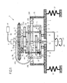
- Fig. 1 to 3 show in different views an embodiment of a centrifuge device 1, which has a rotatable rotor 3 and a rotatable centrifuge chamber 5.
- the centrifuge device 1 is designed in the manner of a non-skid flow centrifuge, in which the centrifuge chamber 5 is connected via a hose 8 to a port 9 to establish a flow connection to external equipment such as a pump bed 91 or liquid containers such as transfusion through another hose 90.
- the tube 8 is fixedly connected to the centrifuge chamber 5 with a first end 80 and fixed to the connection 9 with a second end 81.
- the tube 8 is guided on a passage 35 on the rotor 3, wherein the rotor 3 rotates in operation of the centrifuge device 1 with a first rotational speed V1, which is half as large as the rotational speed V3 of the centrifuge chamber 5.
- the centrifuge device 1 realized on this Way the so-called 2-omega principle (Adams principle), accordingly by tracking the tube 8 with fixed connection of its ends 80, 81 to the centrifuge chamber 5 on the one hand and the connection 9 on the other hand twisting of the tube 8 during a rotary movement of the centrifuge chamber. 5 is prevented.
- liquids in particular blood
- centrifuge chamber 5 liquids, in particular blood
- liquids can be prepared by separating individual components by centrifugation from other constituents.
- a concentrate of red blood cells can be obtained, which can be recycled in a purified form to a patient.
- the rotor 3 is rotatably mounted about an axis of rotation D1 which corresponds to the axis of rotation D3 of the centrifuge chamber 5.
- a planetary gear 41 is rotatably mounted about bearings 31, 32 about an eccentrically arranged, but parallel to the rotational axis D1 of the rotor 3 rotational axis D2, which is part of a drive train 4 for transmitting a rotary motion from the rotor 3 to the centrifuge chamber 5 ,
- the planetary gear 41 is as out Fig. 2 seen, designed in the manner of a circular disc and carries on its outer peripheral surface magnetic means 410 in the form of individual magnets, which are arranged with alternating polarity on the outer cylindrical surface of the planetary gear 41.
- the magnetic means 410 interact with magnetic means 200 in the form of alternating polarity magnets 200 disposed on a stator 20 (see FIG Fig. 2 ) such that upon a rotational movement of the rotor 3 about its associated axis of rotation D1, the planetary gear 41 is displaced in an opposite rotational movement about the axis of rotation D2.
- the magnetic means 410, 200 cause an interaction between the planetary gear 41 and the stator 20, which corresponds in effect to a positive (gear) engagement.
- the axis of rotation D2 of the planetary gear 41 is moved eccentrically about the rotational axis D1 of the rotor 3, with the result that the planetary gear 41 rolls on the stator 20 and thus in an opposite rotational movement to Rotor 3 is offset.
- 200 may also be provided a toothing engagement.
- an external toothing is arranged on the planetary gear 41, which is in engagement with an internal toothing on the stator 20 such that during a rotational movement of the rotor 3, the planetary gear 41 rolls on the stator 20 and is thus set in a rotational movement.
- the planetary gear 41 is arranged on a shaft 40, via which the planetary gear 41 is rotatably mounted on the rotor 3 via the bearings 31, 32. With the shaft 40, a drive wheel 42 is also connected, which is connected via a toothing 420 with a toothing 500 of a chamber wheel 50 of the centrifuge chamber 5 in engagement.
- the drive wheel 42 rotates in the same direction and at the same rotational speed and the chamber wheel 50 and above the centrifuge chamber 5 in a rotational movement in the opposite direction to the rotational movement of the drive wheel 42 and the planetary gear 41 and thus in the same direction to the rotational movement of the rotor 3.
- the stator 20, with respect to the planetary gear 41 constitutes a sun gear about which the planetary gear 41 revolves during operation of the centrifuge device 1 and by means of which the planetary gear 41 is set in rotational motion relative to the rotor 3.
- the sun gear formed by the stator 20 with its magnetic means 200 and the planetary gear 41 with its magnetic means 410 are in this case in the same axial plane.
- the centrifuge device 1 In operation, the centrifuge device 1, a drive device 7, which is arranged on a fixedly connected to the stator 20 and for vibration isolation of the centrifuge device 1 via support springs 22 relative to the environment supported stator housing 2, via a motor shaft 70, the rotor 3 in a rotational movement about the Rotor 3 associated rotational axis D1 in a rotational direction A1 (the introduction of the torque in the rotor 3 via a locking device 6, as will be explained below). Due to the rotational movement of the rotor 3, the planetary gear 41 rotates in the stator 20 and in turn is set in a rotational movement which is transmitted to the centrifuge chamber 5 via the drive wheel 42 and the chamber wheel 50.
- the drive train 4 in this case implements a transmission gear in which the rotational movement of the rotor 3 is translated in a translated manner into a rotational movement of the centrifuge chamber 5 such that the centrifuge chamber 5 rotates during operation of the centrifuge device 1 with twice the rotational speed V3 with respect to the rotational speed V1 of the rotor 3 ,
- the total transmission ratio of the drive train 4 is thus 2, wherein the translation is carried out in two stages such that the rotational movement of the rotor 3 is transmitted in a translated manner to the planetary gear 41 and the rotational movement of the planetary gear 41 in turn translated in a rotational movement of the centrifuge chamber 5.
- the planetary gear 41 can rotate at a rotational speed V2 which corresponds to the amount of 1.66 times the rotational speed V1 of the rotor 3.
- the rotational speed V2 of the planetary gear 41 is then by means of the drive wheel 42 and the Kammerrads 50th translated into the rotational speed V3 of the centrifuge chamber 5, which corresponds to twice the rotational speed V1 of the rotor 3.
- the drive device 7 for example configured by an electric motor, engages via its motor shaft 70 with a locking wheel 60 of a locking device 6 and transmits in the normal operation of the centrifuge device 1 a torque via the locking wheel 60 and three operating wheels 61 (see Fig. 3
- the motor shaft 60 is rotatably supported by a bearing 30 on the rotor 3 and is fixedly connected to the locking wheel 60, which in turn is in meshing engagement with the operating wheels 61.
- the operating wheels 61 are each arranged on a shaft 62, which is mounted on bearings 33, 34 about a fourth axis of rotation D4 pivotally mounted on the rotor 3 (see Fig. 1 ).
- the motor shaft 70 is rotated in a rotational direction A1 about the rotation axis D1, so that the locking wheel 60 rotates accordingly.
- the locking wheel 60 acts on the three associated operating wheels 61 (see Fig. 3 ), which abut against a respective stop 36 in such a direction of rotation of the locking wheel 60 and thus can not be moved relative to the rotor 3.
- the rotor 3 is entrained and offset in a rotational movement in the direction of rotation A1 about the axis of rotation D1, which, as described above, is transmitted via the drive train 4 in a translated manner to the centrifuge chamber 5.
- the locking device 6 is configured to axially lock the centrifuge chamber 5 via locking rollers 64 coupled to a locking eccentric 63 in such a way that the centrifuge chamber 5 can not move axially along the associated axis of rotation D3 relative to the rotor 3 in a locked position.
- Each locking roller 64 is mounted for this purpose via a bearing 640 on the respective associated locking eccentric 63 and has a groove 641 which is in a locked state with a circumferential ridge 51 on the centrifuge chamber 5 is engaged, so that the centrifuge chamber 5 held axially in position becomes.
- a total of three operating wheels 61 are arranged, each associated with a locking eccentric 63 having a locking roller 64 disposed thereon, so that a total of three locking eccentric 63 and three locking rollers 64 are present.
- the operating wheels 61 are each configured in the illustrated embodiment in the manner of a quarter-circle. Conceivable, however, are other types.
- the locking eccentrics 63 are rotated together with the rotor 3 at the rotational speed V1 of the rotor 3 about the axis of rotation D1. Because the centrifuge chamber 5 moves at twice the rotational speed V3, the locking rollers 64 roll on the web 51 and are thus rotated about the associated locking eccentric 64, however, the locking engagement of the web 51 remains in the grooves 641 remains.
- the locking device 6 may have a locked state (shown in FIG Fig. 1 ) and an unlocked state.
- the locked state the locking rollers 64 are in each case via their groove 641 with the circumferential ridge 51 of the centrifuge chamber 5 in engagement, so that the centrifuge chamber 5 is axially fixed.
- the unlocked state however, the locking rollers 64 are radially away from the web 51, so that the web 51 no longer engages in the grooves 641 of the locking rollers 64 and the centrifuge chamber 5 can thus be removed from the rotor 3.
- the locking eccentric 64 The actuation of the locking eccentric 64 via the operating wheels 61.
- the locking device 6 In a normal operating condition in which the rotor 3 is driven via the locking device 6 and the operating wheels 61 each with the associated stop 36 in abutment, the locking device 6 is in this case in their locked Position in which the centrifuge chamber 5 is fixed axially. In this locked position, the operating wheels 61 are held by the force of the drive device 7 in abutment with the stopper 36.
- the locking device 6 If the locking device 6 is to be transferred to its unlocked state, then, after stopping the rotor 3 and the centrifuge chamber 5, by reversing the direction of rotation of the drive device 7 and driving the motor shaft 70 in an opposite direction of rotation A2 (see Fig. 1 ), the operating wheels 61 about their respective associated eccentric axis of rotation D4 in a rotational direction A2 '(see Fig. 3 ) pivoted, so that on the respectively associated locking eccentric 63 the Locking rollers 64 are moved and brought out of engagement from the circumferential ridge 51 of the centrifuge chamber 5.
- the driving of the rotor 3 and the actuation of the locking device 6 thus takes place via the same drive device 7, which either drives the rotor 3 in response to its direction of rotation A1, A2 and causes a rotational movement or the operating wheels 61 with the rotor 3 stationary relative to the rotor 3 moved and adjusted in this way the locking device 6.
- a respective torsion spring 620 is arranged, which the actuating wheel 61 in its locked position (see Fig. 3 ), so that the locking device 6 automatically locks when no adjusting force is introduced via the drive device 7.
- the torsion spring 620 does not necessarily have to be arranged on the shaft 62, but can, for example, also act on the motor shaft 70.
- the rotor 3 is mounted on the stator housing 2 via a freewheel 21.
- the freewheel 21 in this case rotatably supports the rotor 3 when the rotor 3 is rotated in the direction of rotation A1 for driving the centrifuge chamber 5. If the drive direction 7, however, operated in the reverse direction of rotation A2 to actuate the locking device 6, the freewheel 21 blocks a movement of the rotor 3 relative to the stator housing 2, so that the rotor 3 can not be taken and fixed in position on the Stator housing 2 is held.
Landscapes
- Chemical & Material Sciences (AREA)
- Chemical Kinetics & Catalysis (AREA)
- Centrifugal Separators (AREA)
- One-Way And Automatic Clutches, And Combinations Of Different Clutches (AREA)
- External Artificial Organs (AREA)
Abstract
Eine Zentrifugenvorrichtung (1) umfasst eine Antriebsvorrichtung (7), einen um eine erste Drehachse (D1) drehbar gelagerten Rotor (3), der mittels der Antriebsvorrichtung (7) in eine Drehbewegung um die erste Drehachse (D1) versetzbar ist, ein Planetenrad (41), das um eine von der ersten Drehachse (D1) unterschiedliche, zweite Drehachse (D2) drehbar an dem Rotor (3) gelagert ist, einen Stator (20), der mit dem Planetenrad (41) in Wirkverbindung steht derart, dass bei einer Drehbewegung des Rotors (3) das Planetenrad (41) sich um die zweite Drehachse (D2) dreht, und eine um eine dritte Drehachse (D3) drehbar angeordnete Zentrifugenkammer (5), die mit dem Planetenrad (41) in Wirkverbindung steht derart, dass bei einer Drehbewegung des Planetenrads (41) um die zweite Drehachse (D2) die Zentrifugenkammer (5) in eine Drehbewegung versetzt wird. Dabei ist vorgesehen, dass die erste Drehachse (D1) und die zweite Drehachse (D2) parallel zueinander gerichtet sind. Auf diese Weise wird eine Zentrifugenvorrichtung zur Verfügung gestellt, die eine kompakte Bauform bei geringer Bauteileanzahl sowie einfacher Konstruktion ermöglicht.
Description
- Die Erfindung betrifft eine Zentrifugenvorrichtung nach dem Oberbegriff des Anspruchs 1 sowie ein Verfahren zum Betreiben einer Zentrifugenvorrichtung.
- Eine derartige Zentrifugenvorrichtung umfasst eine Antriebsvorrichtung, einen um eine erste Drehachse drehbar gelagerten Rotor, der mittels der Antriebsvorrichtung in eine Drehbewegung um die erste Drehachse versetzbar ist, ein Planetenrad, das um eine von der ersten Drehachse unterschiedliche, zweite Drehachse drehbar an dem Rotor gelagert ist, und einen Stator, der mit dem Planetenrad in Wirkverbindung steht derart, dass bei einer Drehbewegung des Rotors das Planetenrad sich um die zweite Drehachse dreht. Weiter ist eine um eine dritte Drehachse drehbar angeordnete Zentrifugenkammer vorgesehen, die mit dem Planetenrad in Wirkverbindung steht derart, dass bei einer Drehbewegung des Planetenrads um die zweite Drehachse die Zentrifugenkammer in eine Drehbewegung versetzt wird.
- Eine solche Zentrifugenvorrichtung kann insbesondere eine so genannte gleitdichtungsfreie Durchflusszentrifuge verwirklichen, die beispielsweise zur Zellseparation oder als Autotransfusionsgerät zum Einsatz kommen kann. Bei Verwendung zur Autotransfusion beispielsweise wird im Rahmen einer Operation Blut eines Patienten an einem Operationsort abgesaugt, das innerhalb des Autotransfusionsgeräts aufbereitet und anschließend dem Patienten wieder zugeführt wird. Ein wesentliches Bauteil eines solchen Autotransfusionsgeräts stellt die Zentrifugenkammer dar, in der rote Blutkörperchen von anderen Blutbestandteilen separiert und mit einer Kochsalzlösung gewaschen werden, um dann in gereinigter und konzentrierter Form dem Patienten wiederum zugeführt zu werden. Die Aufbereitung läuft hierbei kontinuierlich ab, indem Blut die rotierende Zentrifugenkammer durchfließt und ein Konzentrat roter Blutkörperchen z.B. in einen Retransfusionsbeutel gefördert wird.
- Um einen Durchfluss durch die Zentrifugenkammer ermöglichen zu können, ist bei solchen Zentrifugenvorrichtungen regelmäßig erforderlich, dass ein oder mehrere Schläuche hin zu der Zentrifugenkammer geführt werden, um die Zentrifugenkammer strömungstechnisch beispielsweise mit einem Pumpenbett zu verbinden. Um dabei ein Verwinden der Schläuche im Betrieb der Zentrifugenvorrichtung aufgrund der Drehbewegung der Zentrifugenkammer zu vermeiden, verwirklichen solche Zentrifugenvorrichtungen das so genannte 2-Omega-Prinzip (auch bezeichnet als Adams-Prinzip), demgemäß die Schläuche mit der halben Drehgeschwindigkeit der Zentrifugenkammer der Zentrifugenkammer nachgeführt werden. Dies ermöglicht eine feste Verbindung der Schläuche einerseits mit beispielsweise einem Pumpenbett und andererseits mit der Zentrifugenkammer, ohne dass die Schläuche im Betrieb der Zentrifugenvorrichtung in sich verdreht (verwunden) werden.
- Die Schläuche können hierzu beispielsweise an dem Rotor der Zentrifugenvorrichtung geführt werden, wobei der Rotor sich mit der halben Drehgeschwindigkeit der Zentrifugenkammer dreht und die Schläuche somit der Zentrifugenkammer nachführt.
- Unterschiedliche Antriebskonzepte zum Antreiben des Rotors und der Zentrifugenkammer sind vorgeschlagen worden. Diesen Antriebskonzepten ist gemein, dass sie einen vergleichsweise großen Bauraum der Zentrifugenvorrichtung erforderlich machen und vergleichsweise aufwendig in ihrer Konstruktion sind.
- Eine herkömmliche, beispielsweise aus der
DE 32 42 541 C2 bekannte Zentrifugenvorrichtung verwendet einen Riemenantrieb zur Übertragung eines Drehmoments von einer Antriebswelle auf eine Zentrifugenkammer. Solche Riemenantriebe erfordern einen erheblichen Bauraum und können zudem verschleißanfällig sein. - Bei einer aus der
EP 0 930 099 A2 bekannten Zentrifugenvorrichtung ist ein Rotor mit einer daran drehbar gelagerten Zentrifugenkammer vorgesehen, der eine Drehbewegung in übersetzter Weise über Kopplungselemente auf die Zentrifugenkammer überträgt derart, dass sich die Zentrifugenkammer im Betrieb der Zentrifugenvorrichtung mit doppelter Drehgeschwindigkeit gegenüber dem Rotor dreht. Die Kopplungselemente sind hierbei als um horizontale Drehachsen drehbar an dem Rotor gelagerte Kegelräder ausgestaltet, die einerseits mit einem Stator und andererseits mit der Zentrifugenkammer zusammenwirken derart, dass ein Übersetzungsgetriebe zur Übersetzung der Drehbewegung des Rotors auf die Zentrifugenkammer geschaffen wird. - Obwohl bei der Lösung der
EP 0 930 099 A2 auf ein Riemengetriebe verzichtet werden kann, erfordert die Zentrifugenvorrichtung insbesondere in axialer Richtung (entlang der Drehachse des Rotors) einen vergleichsweise großen Bauraum. - Es besteht ein Bedürfnis nach einer Zentrifugenvorrichtung, die einfach aufgebaut ist, einen geringen Bauraumbedarf aufweist und eine vergleichsweise geringe Anzahl an Bauteilen benötigt.
- Aufgabe der vorliegenden Erfindung ist es, eine Zentrifugenvorrichtung und ein Verfahren zum Betreiben einer Zentrifugenvorrichtung zur Verfügung zu stellen, die eine kompakte Bauform der Zentrifugenvorrichtung bei geringer Bauteileanzahl sowie einfacher Konstruktion ermöglichen.
- Diese Aufgabe wird durch einen Gegenstand mit den Merkmalen des Anspruchs 1 gelöst.
- Demnach sind bei einer Zentrifugenvorrichtung der eingangs genannten Art die erste Drehachse und die zweite Drehachse parallel zueinander gerichtet.
- Die vorliegende Erfindung geht von dem Gedanken aus, die erste Drehachse, um die der Rotor drehbar gelagert ist, und die zweite Drehachse, um die das Planetenrad zur Übertragung einer Drehbewegung auf die Zentrifugenkammer drehbar gelagert ist, parallel zueinander anzuordnen, so dass die Drehebenen des Rotors und des Planetenrads parallel zueinander gerichtet sind. Im Betrieb wird der Rotor über die Antriebsvorrichtung angetrieben und nimmt das drehbar an dem Rotor gelagerte Planetenrad mit. Durch Wechselwirkung des Planetenrads mit dem Stator wird dabei das Planetenrad in eine Drehbewegung relativ zu dem Rotor um die exzentrisch zur ersten Drehachse angeordnete, zweite Drehachse versetzt, wobei das Planetenrad diese Drehbewegung über ein geeignetes Getriebe auf die Zentrifugenkammer überträgt und darüber die Zentrifugenkammer in eine Drehbewegung versetzt.
- Dadurch, dass die Drehachse des Rotors und des Planetenrads parallel zueinander ausgerichtet sind, kann die Zentrifugenvorrichtung in axialer Richtung kompakt aufgebaut werden. Die Zentrifugenvorrichtung kann dabei eine geringe Anzahl von Bauteilen verwenden und kann auf Riemengetriebe verzichten, was vorteilhaft hinsichtlich der Verschleißeigenschaften und des Bauraumbedarfs der Zentrifugenvorrichtung ist. Durch die Reduktion der Anzahl der erforderlichen Bauteile und durch die erreichbare Einfachheit im Aufbau ergibt sich zudem ein Kosteneinsparungspotential für die Herstellung solcher Zentrifugenvorrichtungen.
- Vorteilhafterweise dreht sich der Rotor mit einer ersten Drehgeschwindigkeit und die Zentrifugenkammer mit einer im Vergleich zur ersten Drehgeschwindigkeit doppelt so großen, zweiten Drehgeschwindigkeit. Der Rotor kann hierbei einen oder mehrere Schläuche zur Verbindung der Zentrifugenkammer mit externen Gerätschaften, beispielsweise einem Pumpenbett oder Flüssigkeitsbehältern wie Transfusionsbeuteln, führen, so dass der Rotor die daran angeordneten Schläuche mit halber Drehgeschwindigkeit im Vergleich zur Drehgeschwindigkeit der Zentrifugenkammer nachführt. Dies ermöglicht nach dem sogenannten 2-Omega-Prinzip (Adams-Prinzip) eine feste Verbindung der Schläuche einerseits mit der Zentrifugenkammer und andererseits mit den externen Gerätschaften, ohne dass im Betrieb der Zentrifugenkammer die Schläuche verwinden
- Im Betrieb der Zentrifugenvorrichtung wird der Rotor über die Antriebsvorrichtung in eine Drehbewegung versetzt. Der Rotor nimmt dabei das exzentrisch zum Rotor drehbar gelagerte Planetenrad mit, wobei das Planetenrad durch Wechselwirkung mit dem Stator in eine (exzentrische) Drehbewegung relativ zu dem Rotor versetzt wird. Die Wechselwirkung zwischen dem Planetenrad und dem Stator kann beispielsweise über an dem Stator angeordnete magnetische Mittel erfolgen, die mit magnetischen Mitteln des Planetenrads zur Herstellung der Wirkverbindung zwischen dem Stator und dem Planetenrad wechselwirken. Die magnetischen Mittel an dem Stator und an dem Planetenrad können beispielsweise durch umfänglich an dem Stator bzw. dem Planetenrad angeordnete Magnete verwirklicht sein, wobei die Magnete an dem Stator und an dem Planetenrad jeweils eine alternierende Polung aufweisen, so dass auf einen Nordpol eines Magneten jeweils ein Südpol folgt und umgekehrt.
- Der Stator bildet auf diese Weise ein Sonnenrad mit an einer Innenumfangsfläche angeordneten Magneten aus, das konzentrisch zur (ersten) Drehachse des Rotors ist und bei einer Drehbewegung des Rotors ortsfest bleibt und sich nicht mitdreht. Die magnetischen Mittel des Planetenrads sind hingegen an einer äußeren zylindrischen Mantelfläche des Planetenrads angeordnet und wechselwirken mit den magnetischen Mitteln des Stators bei einer Drehbewegung des Rotors derart, dass das Planetenrad nach Art eines formschlüssigen Eingriffs am Stator abrollt und auf diese Weise relativ zum Rotor gedreht wird. Durch Verwendung solcher magnetischer Mittel am Stator und am Rotor wird jedoch - im Vergleich zu beispielsweise einem Verzahnungseingriff - eine berührungslose Wechselwirkung bereitgestellt, die verschleißfrei ist und zudem keine Geräusche verursacht, so dass die Geräuschentwicklung an der Zentrifugenvorrichtung im Betrieb reduziert ist.
- Alternativ kann der Stator anstelle der magnetischen Mittel auch eine Verzahnung tragen, die mit einer Verzahnung des Planetenrads in Eingriff ist. Der Stator bildet in diesem Fall wiederum ein Sonnenrad bezüglich des Planetenrads aus, an dem das Planetenrad bei einer Drehung des Rotors abrollt derart, dass das Planetenrad bei einer Drehbewegung des Rotors relativ zu dem Rotor gedreht wird.
- Mittels des Planetenrads wird die Drehbewegung in übersetzter Weise auf die Zentrifugenkammer übertragen, so dass im Betrieb der Zentrifugenvorrichtung mittels einer einzigen Antriebsvorrichtung der Rotor und in übersetzter Weise auch die Zentrifugenkammer gedreht werden. Das Planetenrad kann hierzu mit einem Kammerrad der Zentrifugenkammer in Wirkverbindung stehen, wobei hierzu das Planetenrad beispielsweise drehfest mit einem Antriebsrad gekoppelt ist, das beispielsweise über eine Verzahnung mit einer Verzahnung des Kammerrads in Eingriff steht.
- Mittels des ein Sonnenrad verwirklichenden Stators, des Planetenrads, des Antriebsrads und des Kammerrads kann die Übersetzung der Drehbewegung des Rotors auf die Zentrifugenkammer eingestellt werden. Denkbar ist hierbei, dass bereits das Planetenrad sich mit doppelter Drehgeschwindigkeit relativ zum Rotor (aber mit entgegengesetztem Drehsinn) dreht, um dann mit einer 1:-1-Übersetzung das Kammerrad anzutreiben und somit die Zentrifugenkammer im gleichen Drehsinn und mit doppelter Drehgeschwindigkeit im Vergleich zum Rotor zu drehen. Denkbar ist aber auch, dass das Planetenrad zusammen mit dem Stator, dem Antriebsrad und dem Kammerrad eine zweistufige Übersetzung verwirklicht, bei dem das Planetenrad sich mit einer Drehgeschwindigkeit dreht, die größer als die Drehgeschwindigkeit des Rotors, aber kleiner als die Drehgeschwindigkeit der Zentrifugenkammer ist. Beispielsweise kann die Drehgeschwindigkeit des Planetenrads (bei entgegengesetztem Drehsinn) der 1,66-fachen Drehgeschwindigkeit des Rotors entsprechen, wobei die Drehgeschwindigkeit des Planetenrads dann über das Antriebsrad und das Kammerrad übersetzt wird, um die Zentrifugenkammer mit doppelter Drehgeschwindigkeit gleichsinnig zum Rotor zu drehen.
- Vorteilhafterweise ist die dritte Drehachse (der Zentrifugenkammer) kollinear, also konzentrisch, zur ersten Drehachse (des Rotors) angeordnet. Die Zentrifugenkammer und der Rotor drehen sich somit um dieselbe Drehachse.
- Im Betrieb der Zentrifugenvorrichtung ist die Zentrifugenkammer axial festgelegt und steht über das Planetenrad mit dem Rotor in Wirkverbindung, so dass durch Antreiben des Rotors mittels der Antriebsvorrichtung die Zentrifugenkammer gedreht werden kann. Um die Zentrifugenkammer hierbei an dem Rotor zu halten, ist vorteilhafter Weise eine Verriegelungseinrichtung vorgesehen, die an dem Rotor angeordnet ist und sich bei einer Drehbewegung des Rotors um die dem Rotor zugeordnete erste Drehachse zusammen mit dem Rotor dreht. Die Verriegelungseinrichtung dient dazu, die Zentrifugenkammer in axialer Richtung zur der Zentrifugenkammer zugeordneten dritten Drehachse festzulegen, so dass die Zentrifugenkammer axial an dem Rotor gehalten ist und im Betrieb der Zentrifugenvorrichtung sich axial nicht zu dem Rotor bewegen kann.
- Die Verriegelungseinrichtung kann hierzu ein um eine vierte Drehachse an dem Rotor schwenkbar gelagertes Betätigungsrad aufweisen, das mit einem Verriegelungsexzenter gekoppelt ist derart, dass die Zentrifugenkammer durch eine Schwenkbewegung des Betätigungsrads um die vierte Drehachse axial verriegelbar oder zum Entnehmen entriegelbar ist. Hierzu kann der Verriegelungsexzenter in einer verriegelten Stellung über eine Verriegelungsrolle mit der Zentrifugenkammer verriegelnd in Eingriff stehen, wobei der Eingriff gelöst werden kann, so dass der Verriegelungsexzenter in einer entriegelten Stellung nicht mehr mit der Zentrifugenkammer in Eingriff steht und die Zentrifugenkammer von dem Rotor entnommen werden kann.
- Der Verriegelungsexzenter ist vorteilhafterweise in Richtung der verriegelten Stellung elastisch vorgespannt, so dass, wenn das Betätigungsrad nicht betätigt wird, der Verriegelungsexzenter selbsttätig in seine verriegelnde Stellung gelangt und die Zentrifugenkammer somit an dem Rotor verriegelt ist. Zum elastischen Vorspannen kann beispielsweise eine mechanische Feder, beispielsweise eine Drehfeder, vorgesehen sein, wobei grundsätzlich aber auch andere Mittel zum Vorspannen möglich und denkbar sind.
- Die Verriegelungseinrichtung kann grundsätzlich nur einen einzigen Verriegelungsexzenter aufweisen, der verriegelnd mit der Zentrifugenkammer zum axialen Festlegen der Zentrifugenkammer an dem Rotor in Eingriff steht. Vorteilhaft ist aber, wenn die Verriegelungseinrichtung zwei oder mehr, beispielsweise drei Verriegelungsexzenter aufweist, die jeweils mit einem zugeordneten Betätigungsrad in Wirkverbindung stehen, wobei durch Betätigen der Betätigungsräder die einzelnen Verriegelungsexzenter bewegt und dadurch verriegelnd in Eingriff oder entriegelnd außer Eingriff mit der Zentrifugenkammer gebracht werden können.
- In einer vorteilhaften Ausgestaltung kann die Antriebsvorrichtung einerseits zum Antreiben des Rotors im normalen Betrieb der Zentrifugenvorrichtung und andererseits zum Betätigen der Verriegelungseinrichtung zum Verriegeln und/oder zum Entriegeln der Zentrifugenkammer dienen. Hierzu kann vorgesehen sein, dass die Antriebsvorrichtung bei einer Drehbewegung einer Motorwelle der Antriebsvorrichtung in eine erste Drehrichtung um die erste Drehachse den Rotor zum Antreiben der Zentrifugenkammer durch Krafteinleitung über das Betätigungsrad mitnimmt. Über das Betätigungsrad wird somit ein Drehmoment auf den Rotor übertragen, indem das Betätigungsrad bei einer Drehbewegung in die erste Drehrichtung beispielsweise an einem zugeordneten Anschlag anschlägt, so dass das Betätigungsrad sich nicht relativ zu dem Rotor verdrehen kann und der Rotor somit in eine Drehbewegung um seine zugeordnete (erste) Drehachse versetzt wird. Bei einer Drehbewegung der Motorwelle in eine der ersten Drehrichtung entgegengesetzte, zweite Drehrichtung hingegen wird der Rotor nicht mitgenommen und das Betätigungsrad somit relativ zu dem Rotor verstellt, so dass die Verriegelungseinrichtung über das Betätigungsrad betätigt wird.
- Die Verriegelungseinrichtung kann zur Kopplung mit der Antriebsvorrichtung beispielsweise ein Verriegelungsrad aufweisen, das um die erste Drehachse drehbar mit der Motorwelle der Antriebsvorrichtung gekoppelt ist, so dass das Verriegelungsrad bei einer Drehbewegung des Motors um die erste Drehachse verdreht wird. Das Verriegelungsrad steht mit dem um die vierte Drehachse exzentrisch zum Verriegelungsrad angeordneten Betätigungsrad beispielsweise über Verzahnungen in Eingriff, wobei bei Antreiben des Verriegelungsrads in die erste Drehrichtung das Betätigungsrad an einen Anschlag oder dergleichen an dem Rotor anschlägt und somit nicht relativ zu dem Rotor verdreht werden kann, so dass - angetrieben durch das Verriegelungsrad - der Rotor mitgenommen und in eine Drehbewegung in die erste Drehrichtung um die erste Drehachse versetzt wird. Wird das Verriegelungsrad hingegen in die entgegengesetzte, zweite Drehrichtung angetrieben, so kann das Betätigungsrad sich relativ zu dem Rotor verstellen, um auf diese Weise die Verriegelungseinrichtung beispielsweise zum Entriegeln der Zentrifugenkammer zu betätigen.
- Der Rotor ist vorteilhafterweise über einen Freilauf an einem Statorgehäuse der Zentrifugenvorrichtung angeordnet. Der Freilauf ist hierbei derart beschaffen, dass er bei einer Drehbewegung der Motorwelle in die erste Drehrichtung den Rotor drehbar lagert, so dass sich der Rotor frei gegenüber dem Statorgehäuse drehen kann, um eine Drehbewegung auf das Planetenrad und darüber auf die Zentrifugenkammer zu übertragen. Bei einer Drehbewegung der Motorwelle in die entgegengesetzte, zweite Drehrichtung hingegen sperrt der Freilauf den Rotor, so dass der Rotor nicht relativ zu dem Statorgehäuse bewegt werden kann und somit festgehalten wird. Beim Betreiben der Antriebsvorrichtung in die zweite Drehrichtung wird somit über das Verriegelungsrad das einem Verriegelungsexzenter zugeordnete Betätigungsrad betätigt, so dass die Verriegelungseinrichtung beispielsweise entriegelt wird und die Zentrifugenkammer somit von dem Rotor entnommen werden kann.
- Die Aufgabe wird weiterhin durch ein Verfahren zum Betreiben einer Zentrifugenvorrichtung gelöst, bei dem
- eine Antriebsvorrichtung einen um eine erste Drehachse drehbar gelagerten Rotor in eine Drehbewegung um die erste Drehachse versetzt,
- ein Planetenrad, das um eine von der ersten Drehachse unterschiedliche, zweite Drehachse drehbar an dem Rotor gelagert ist und mit einem Stator in Wirkverbindung steht, bei einer Drehbewegung des Rotors sich um die zweite Drehachse dreht und
- eine um eine dritte Drehachse drehbar angeordnete Zentrifugenkammer bei einer Drehbewegung des Planetenrads um die zweite Drehachse in eine Drehbewegung versetzt wird.
- Dabei ist vorgesehen, dass die erste Drehachse und die zweite Drehachse parallel zueinander gerichtet sind.
- Zu Vorteilen und vorteilhaften Ausgestaltungen des Verfahrens wird auf das vorangehend zur Zentrifugenvorrichtung Ausgeführte verwiesen, das analog auch auf das Verfahren Anwendung findet.
- Der der Erfindung zugrundeliegende Gedanke soll nachfolgend anhand der in den Figuren dargestellten Ausführungsbeispiele näher erläutert werden. Es zeigen:
- Fig. 1
- eine schematische Schnittansicht durch eine Zentrifugenvorrichtung mit einem Rotor und einem daran angeordneten Planetenrad;
- Fig. 2
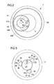
- eine schematische Draufsicht auf den Rotor und das daran angeordnete Planetenrad im Zusammenwirken mit einem Stator; und
- Fig. 3
- eine schematische Draufsicht auf den Rotor und daran angeordnete Betätigungsräder.
-
Fig. 1 bis 3 zeigen in unterschiedlichen Ansichten ein Ausführungsbeispiel einer Zentrifugenvorrichtung 1, die einen drehbaren Rotor 3 und eine drehbare Zentrifugenkammer 5 aufweist. - Die Zentrifugenvorrichtung 1 ist nach Art einer gleitdichtungsfreien Durchflusszentrifuge ausgebildet, bei der die Zentrifugenkammer 5 über einen Schlauch 8 mit einem Anschluss 9 verbunden ist, um über einen weiteren Schlauch 90 eine Strömungsverbindung zu externen Gerätschaften wie beispielsweise einem Pumpenbett 91 oder Flüssigkeitsbehältern wie Transfusionsbeuteln herzustellen. Der Schlauch 8 ist hierbei mit einem ersten Ende 80 fest mit der Zentrifugenkammer 5 und mit einem zweiten Ende 81 fest mit dem Anschluss 9 verbunden.
- Der Schlauch 8 ist an einer Durchführung 35 an dem Rotor 3 geführt, wobei sich der Rotor 3 im Betrieb der Zentrifugenvorrichtung 1 mit einer ersten Drehgeschwindigkeit V1 dreht, die halb so groß ist wie die Drehgeschwindigkeit V3 der Zentrifugenkammer 5. Die Zentrifugenvorrichtung 1 verwirklicht auf diese Weise das so genannte 2-Omega-Prinzip (Adams-Prinzip), demgemäß durch Nachführung des Schlauchs 8 bei fester Anbindung seiner Enden 80, 81 an die Zentrifugenkammer 5 einerseits und den Anschluss 9 andererseits ein Verwinden des Schlauchs 8 bei einer Drehbewegung der Zentrifugenkammer 5 verhindert wird.
- Mittels der Zentrifugenkammer 5 können beispielsweise Flüssigkeiten, insbesondere Blut, aufbereitet werden, indem einzelne Bestandteile durch Zentrifugation von anderen Bestandteilen separiert werden. Beispielsweise kann im Rahmen einer Autotransfusion ein Konzentrat roter Blutkörperchen gewonnen werden, das in gereinigter Form einem Patienten wieder zugeführt werden kann.
- Der Rotor 3 ist um eine Drehachse D1 drehbar gelagert, die der Drehachse D3 der Zentrifugenkammer 5 entspricht. An dem Rotor 3 ist um eine exzentrisch angeordnete, aber parallel zur Drehachse D1 des Rotors 3 gerichtete Drehachse D2 ein Planetenrad 41 über Lager 31, 32 drehbar gelagert, das Bestandteil eines Antriebsstrangs 4 zur Übertragung einer Drehbewegung von dem Rotor 3 auf die Zentrifugenkammer 5 ist.
- Das Planetenrad 41 ist, wie aus
Fig. 2 ersichtlich, nach Art einer Kreisscheibe ausgestaltet und trägt an seiner äußeren Umfangsfläche magnetische Mittel 410 in Form einzelner Magnete, die mit alternierender Polung an der äußeren zylindrischen Mantelfläche des Planetenrads 41 angeordnet sind. Die magnetischen Mittel 410 bewirken eine Wechselwirkung mit an einem Stator 20 angeordneten magnetischen Mitteln 200 in Form von eine alternierende Polung aufweisenden Magneten (sieheFig. 2 ) derart, dass bei einer Drehbewegung des Rotors 3 um seine zugeordnete Drehachse D1 das Planetenrad 41 in eine gegensinnige Drehbewegung um die Drehachse D2 versetzt wird. - Die magnetischen Mittel 410, 200 bewirken eine Wechselwirkung zwischen dem Planetenrad 41 und dem Stator 20, der in seiner Wirkung einem formschlüssigen (Verzahnungs-)Eingriff entspricht. Bei einer Drehbewegung des Rotors 3 um die zugeordnete Drehachse D1 wird entsprechend die Drehachse D2 des Planetenrads 41 exzentrisch um die Drehachse D1 des Rotors 3 bewegt, was zur Folge hat, dass das Planetenrad 41 an dem Stator 20 abrollt und somit in ein gegensinnige Drehbewegung zum Rotor 3 versetzt wird.
- Anstelle einer Wechselwirkung über die magnetischen Mittel 410, 200 kann auch ein Verzahnungseingriff vorgesehen sein. In diesem Fall ist an dem Planetenrad 41 eine Außenverzahnung angeordnet, die mit einer Innenverzahnung an dem Stator 20 in Eingriff steht derart, dass bei einer Drehbewegung des Rotors 3 das Planetenrad 41 an dem Stator 20 abrollt und somit in eine Drehbewegung versetzt wird.
- Das Planetenrad 41 ist an einer Welle 40 angeordnet, über die das Planetenrad 41 über die Lager 31, 32 drehbar an dem Rotor 3 gelagert ist. Mit der Welle 40 ist zudem ein Antriebsrad 42 verbunden, das über eine Verzahnung 420 mit einer Verzahnung 500 eines Kammerrads 50 der Zentrifugenkammer 5 in Eingriff steht. Dreht sich das Planetenrad 41 im Betrieb der Zentrifugenvorrichtung 1 um seine zugeordnete Drehachse D2, so dreht sich das Antriebsrad 42 gleichsinnig und mit gleicher Drehgeschwindigkeit und versetzt das Kammerrad 50 und darüber die Zentrifugenkammer 5 in eine Drehbewegung, die gegensinnig zur Drehbewegung des Antriebsrads 42 und des Planetenrads 41 und damit gleichsinnig zur Drehbewegung des Rotors 3 ist.
- Der Stator 20 stellt bezüglich des Planetenrads 41 ein Sonnenrad dar, um das das Planetenrad 41 im Betrieb der Zentrifugenvorrichtung 1 umläuft und mittels dessen das Planetenrad 41 in eine Drehbewegung relativ zu dem Rotor 3 versetzt wird. Das durch den Stator 20 mit seinen magnetischen Mitteln 200 gebildete Sonnenrad und das Planetenrad 41 mit seinen magnetischen Mitteln 410 befinden sich hierbei in derselben axialen Ebene.
- Im Betrieb der Zentrifugenvorrichtung 1 versetzt eine Antriebsvorrichtung 7, die an einem fest mit dem Stator 20 verbundenen und zur Schwingungsentkopplung der Zentrifugenvorrichtung 1 über Stützfedern 22 gegenüber der Umgebung abgestützten Statorgehäuse 2 angeordnet ist, über eine Motorwelle 70 den Rotor 3 in eine Drehbewegung um die dem Rotor 3 zugeordnete Drehachse D1 in eine Drehrichtung A1 (das Einleiten des Drehmoments in den Rotor 3 erfolgt über eine Verriegelungseinrichtung 6, wie nachfolgend noch erläutert werden soll). Durch die Drehbewegung des Rotors 3 läuft das Planetenrad 41 in dem Stator 20 um und wird seinerseits in eine Drehbewegung versetzt, die über das Antriebsrad 42 und das Kammerrad 50 auf die Zentrifugenkammer 5 übertragen wird. Der Antriebsstrang 4 verwirklicht hierbei ein Übersetzungsgetriebe, bei dem die Drehbewegung des Rotors 3 in übersetzter Weise in eine Drehbewegung der Zentrifugenkammer 5 übersetzt wird derart, dass sich die Zentrifugenkammer 5 im Betrieb der Zentrifugenvorrichtung 1 mit doppelter Drehgeschwindigkeit V3 gegenüber der Drehgeschwindigkeit V1 des Rotors 3 dreht. Der Gesamtübersetzungsfaktor des Antriebsstrangs 4 beträgt somit 2, wobei die Übersetzung zweistufig erfolgt derart, dass die Drehbewegung des Rotors 3 in übersetzter Weise auf das Planetenrad 41 übertragen wird und die Drehbewegung des Planetenrads 41 wiederum in übersetzter Weise in eine Drehbewegung der Zentrifugenkammer 5 übersetzt wird. So kann sich beispielsweise das Planetenrad 41 mit einer Drehgeschwindigkeit V2 drehen, die im Betrag der 1,66-fachen Drehgeschwindigkeit V1 des Rotors 3 entspricht. Die Drehgeschwindigkeit V2 des Planetenrads 41 wird dann mittels des Antriebsrads 42 und des Kammerrads 50 übersetzt in die Drehgeschwindigkeit V3 der Zentrifugenkammer 5, die der doppelten Drehgeschwindigkeit V1 des Rotors 3 entspricht.
- Die Antriebsvorrichtung 7, beispielsweise ausgestaltet durch einen Elektromotor, steht über ihre Motorwelle 70 mit einem Verriegelungsrad 60 einer Verriegelungseinrichtung 6 in Eingriff und überträgt im normalen Betrieb der Zentrifugenvorrichtung 1 ein Drehmoment über das Verriegelungsrad 60 sowie drei Betätigungsräder 61 (siehe
Fig. 3 ) auf den Rotor 3. Die Motorwelle 60 ist über ein Lager 30 drehbar an dem Rotor 3 gelagert und ist fest mit dem Verriegelungsrad 60 verbunden, das wiederum in Verzahnungseingriff mit den Betätigungsrädern 61 steht. - Die Betätigungsräder 61 sind an jeweils einer Welle 62 angeordnet, die über Lager 33, 34 um eine vierte Drehachse D4 verschwenkbar an dem Rotor 3 gelagert ist (siehe
Fig. 1 ). - Im normalen Betrieb der Zentrifugenvorrichtung 1 wird die Motorwelle 70 in eine Drehrichtung A1 um die Drehachse D1 gedreht, so dass sich das Verriegelungsrad 60 entsprechend dreht. Das Verriegelungsrad 60 wirkt hierbei auf die drei zugeordneten Betätigungsräder 61 (siehe
Fig. 3 ) ein, die bei einem derartigen Drehsinn des Verriegelungsrads 60 an jeweils einem zugeordneten Anschlag 36 anschlagen und somit nicht relativ zu dem Rotor 3 bewegt werden können. Entsprechend wird der Rotor 3 mitgenommen und in eine Drehbewegung in die Drehrichtung A1 um die Drehachse D1 versetzt, die, wie vorangehend geschildert, über den Antriebsstrang 4 in übersetzter Weise auf die Zentrifugenkammer 5 übertragen wird. - Die Verriegelungseinrichtung 6 ist dazu ausgestaltet, über jeweils mit einem Verriegelungsexzenter 63 gekoppelte Verriegelungsrollen 64 die Zentrifugenkammer 5 axial zu verriegeln derart, dass die Zentrifugenkammer 5 sich in einer verriegelten Stellung nicht axial entlang der zugeordneten Drehachse D3 relativ zu dem Rotor 3 bewegen kann. Jede Verriegelungsrolle 64 ist hierzu über ein Lager 640 an dem jeweils zugeordneten Verriegelungsexzenter 63 gelagert und weist eine Nut 641 auf, die in einem verriegelten Zustand mit einem umlaufenden Steg 51 an der Zentrifugenkammer 5 in Eingriff steht, so dass die Zentrifugenkammer 5 axial in Position gehalten wird.
- In der schematischen Schnittansicht gemäß
Fig. 1 ist nur eine Verriegelungsrolle 64 dargestellt, die einem Verriegelungsexzenter 63 und einem Betätigungsrad 61 zugeordnet ist. An dem Rotor 3 sind jedoch, wie ausFig. 3 ersichtlich, gleichverteilt um die Drehachse D1 insgesamt drei Betätigungsräder 61 angeordnet, denen jeweils ein Verriegelungsexzenter 63 mit einer daran angeordneten Verriegelungsrolle 64 zugeordnet ist, so dass insgesamt drei Verriegelungsexzenter 63 und drei Verriegelungsrollen 64 vorhanden sind. - Die Betätigungsräder 61 sind bei dem dargestellten Ausführungsbeispiel jeweils nach Art eines Viertelkreisrades ausgestaltet. Denkbar sind aber auch andere Bauformen.
- Im normalen Betrieb der Zentrifugenvorrichtung 1 werden die Verriegelungsexzenter 63 zusammen mit dem Rotor 3 mit der Drehgeschwindigkeit V1 des Rotors 3 um die Drehachse D1 verdreht. Weil die Zentrifugenkammer 5 sich mit der doppelten Drehgeschwindigkeit V3 bewegt, rollen die Verriegelungsrollen 64 an dem Steg 51 ab und werden somit jeweils um den zugeordneten Verriegelungsexzenter 64 gedreht, wobei der verriegelnde Eingriff des Stegs 51 in die Nuten 641 jedoch bestehen bleibt.
- Die Verriegelungseinrichtung 6 kann einen verriegelten Zustand (dargestellt in
Fig. 1 ) und einen entriegelten Zustand einnehmen. In dem verriegelten Zustand stehen die Verriegelungsrollen 64 jeweils über ihre Nut 641 mit dem umlaufenden Steg 51 der Zentrifugenkammer 5 in Eingriff, so dass die Zentrifugenkammer 5 axial festgelegt ist. In dem entriegelten Zustand hingegen sind die Verriegelungsrollen 64 radial von dem Steg 51 entfernt, so dass der Steg 51 nicht mehr in die Nuten 641 der Verriegelungsrollen 64 eingreift und die Zentrifugenkammer 5 somit von dem Rotor 3 entnommen werden kann. - Die Betätigung der Verriegelungsexzenter 64 erfolgt über die Betätigungsräder 61. In einem normalen Betriebszustand, in dem über die Verriegelungseinrichtung 6 der Rotor 3 angetrieben wird und die Betätigungsräder 61 jeweils mit dem zugeordneten Anschlag 36 in Anlage sind, befindet sich die Verriegelungseinrichtung 6 hierbei in ihrer verriegelten Stellung, in der die Zentrifugenkammer 5 axial festgelegt ist. In dieser verriegelten Stellung werden die Betätigungsräder 61 auch durch die Krafteinwirkung der Antriebsvorrichtung 7 in Anlage mit dem Anschlag 36 gehalten.
- Soll die Verriegelungseinrichtung 6 in ihren entriegelten Zustand überführt werden, so werden hierzu, nach dem Anhalten des Rotors 3 und der Zentrifugenkammer 5, durch Umkehr der Drehrichtung der Antriebsvorrichtung 7 und Antreiben der Motorwelle 70 in eine entgegengesetzte Drehrichtung A2 (siehe
Fig. 1 ), die Betätigungsräder 61 um ihre jeweils zugeordnete exzentrische Drehachse D4 in eine Drehrichtung A2' (sieheFig. 3 ) verschwenkt, so dass über den jeweils zugeordneten Verriegelungsexzenter 63 die Verriegelungsrollen 64 bewegt und außer Eingriff von dem umlaufenden Steg 51 der Zentrifugenkammer 5 gebracht werden. - Das Antreiben des Rotors 3 und die Betätigung der Verriegelungseinrichtung 6 erfolgt somit über dieselbe Antriebsvorrichtung 7, die in Abhängigkeit von ihrer Drehrichtung A1, A2 entweder den Rotor 3 antreibt und in eine Drehbewegung versetzt oder die Betätigungsräder 61 bei stillstehendem Rotor 3 relativ zu dem Rotor 3 bewegt und auf diese Weise die Verriegelungseinrichtung 6 verstellt.
- An der jedem Betätigungsrad 61 zugeordneten Welle 62 ist jeweils eine Drehfeder 620 angeordnet, die das Betätigungsrad 61 in seine verriegelte Stellung (siehe
Fig. 3 ) vorspannt, so dass die Verriegelungseinrichtung 6 selbsttätig verriegelt, wenn keine Verstellkraft über die Antriebsvorrichtung 7 eingeleitet wird. - Die Drehfeder 620 muss nicht zwangsläufig an der Welle 62 angeordnet sein, sondern kann beispielsweise auch auf die Motorwelle 70 einwirken.
- Der Rotor 3 ist über einen Freilauf 21 an dem Statorgehäuse 2 gelagert. Der Freilauf 21 lagert hierbei den Rotor 3 drehbar, wenn der Rotor 3 in die Drehrichtung A1 zum Antreiben der Zentrifugenkammer 5 gedreht wird. Wird die Antriebsrichtung 7 hingegen in die umgekehrte Drehrichtung A2 betrieben, um die Verriegelungseinrichtung 6 zu betätigen, so sperrt der Freilauf 21 eine Bewegung des Rotors 3 relativ zu dem Statorgehäuse 2, so dass der Rotor 3 nicht mitgenommen werden kann und ortsfest in Position an dem Statorgehäuse 2 gehalten wird.
- Der der Erfindung zugrundeliegende Gedanke ist nicht auf die vorangehend geschilderten Ausführungsbeispiele beschränkt, sondern lässt sich auch bei gänzlich anders gearteten Ausführungsformen verwirklichen.
- Denkbar ist beispielsweise, bei einer Verriegelungseinrichtung mehr oder weniger als drei Verriegelungsrollen zum axialen Festlegen der Zentrifugenkammer vorzusehen.
- Denkbar ist zudem, mehr als ein Planetenrad zum Übertragen einer Drehbewegung auf die Zentrifugenkammer vorzusehen. Beispielsweise können auch drei Planetenräder vorgesehen sein, die um die dem Rotor zugeordnete Drehachse verteilt an dem Rotor gelagert sind und in symmetrischer Weise die Zentrifugenkammer antreiben.
-
- 1
- Zentrifugenvorrichtung
- 2
- Statorgehäuse
- 20
- Stator
- 200
- Magnetische Mittel
- 21
- Freilauf
- 22
- Stützfedern
- 3
- Rotor
- 30-34
- Lager
- 35
- Durchführung
- 36
- Anschlag
- 4
- Antriebsstrang
- 40
- Welle
- 41
- Planetenrad
- 410
- Magnetische Mittel
- 42
- Antriebsrad
- 420
- Verzahnung
- 5
- Zentrifugenkammer
- 50
- Kammerrad
- 500
- Verzahnung
- 51
- Umlaufender Steg
- 6
- Verriegelungseinrichtung
- 60
- Verriegelungsrad
- 61
- Betätigungsrad
- 62
- Welle
- 620
- Drehfeder
- 63
- Verriegelungsexzenter
- 64
- Verriegelungsrolle
- 640
- Lager
- 641
- Nut
- 7
- Antriebsvorrichtung (Motor)
- 70
- Motorwelle
- 8
- Schlauch
- 80,81
- Ende
- 9
- Anschluss
- 90
- Schlauch
- 91
- Pumpenbett
- A1, A2, A2'
- Drehrichtung
- D1-D4
- Drehachse
- V1, V2, V3
- Drehgeschwindigkeit
Claims (16)
- Zentrifugenvorrichtung (1), mit- einer Antriebsvorrichtung (7),- einem um eine erste Drehachse (D1) drehbar gelagerten Rotor (3), der mittels der Antriebsvorrichtung (7) in eine Drehbewegung um die erste Drehachse (D1) versetzbar ist,- einem Planetenrad (41), das um eine von der ersten Drehachse (D1) unterschiedliche, zweite Drehachse (D2) drehbar an dem Rotor (3) gelagert ist,- einem Stator (20), der mit dem Planetenrad (41) in Wirkverbindung steht derart, dass bei einer Drehbewegung des Rotors (3) das Planetenrad (41) sich um die zweite Drehachse (D2) dreht, und- einer um eine dritte Drehachse (D3) drehbar angeordneten Zentrifugenkammer (5), die mit dem Planetenrad (41) in Wirkverbindung steht derart, dass bei einer Drehbewegung des Planetenrads (41) um die zweite Drehachse (D2) die Zentrifugenkammer (5) in eine Drehbewegung versetzt wird,
dadurch gekennzeichnet,
dass die erste Drehachse (D1) und die zweite Drehachse (D2) parallel zueinander gerichtet sind. - Zentrifugenvorrichtung (1) nach Anspruch 1, dadurch gekennzeichnet, dass der Rotor (3) sich mit einer ersten Drehgeschwindigkeit (V1) und die Zentrifugenkammer (5) sich mit einer im Vergleich zur ersten Drehgeschwindigkeit (V1) doppelt so großen, zweiten Drehgeschwindigkeit (V3) dreht.
- Zentrifugenvorrichtung (1) nach Anspruch 1 oder 2, dadurch gekennzeichnet, dass der Stator (20) magnetische Mittel (200) trägt, die mit magnetischen Mitteln (410) des Planetenrads (41) zur Herstellung der Wirkverbindung zwischen dem Stator (20) und dem Planetenrad (41) wechselwirken.
- Zentrifugenvorrichtung (1) nach Anspruch 1 oder 2, dadurch gekennzeichnet, dass der Stator (20) eine Verzahnung trägt, die mit einer Verzahnung des Planetenrads (41) zur Herstellung der Wirkverbindung zwischen dem Stator (20) und dem Planetenrad (41) in Eingriff steht.
- Zentrifugenvorrichtung (1) nach einem der vorangehenden Ansprüche, dadurch gekennzeichnet, dass das Planetenrad (41) mit einem Kammerrad (50) der Zentrifugenkammer (5) in Wirkverbindung steht.
- Zentrifugenvorrichtung (1) nach Anspruch 5, dadurch gekennzeichnet, dass das Planetenrad (41) drehfest mit einem Antriebsrad (42) gekoppelt ist und über das Antriebsrad (42) mit dem Kammerrad (50) in Eingriff steht.
- Zentrifugenvorrichtung (1) nach einem der vorangehenden Ansprüche, dadurch gekennzeichnet, dass die dritte Drehachse (D3) und die erste Drehachse (D1) kollinear zueinander ausgerichtet sind.
- Zentrifugenvorrichtung (1) nach einem der vorangehenden Ansprüche, dadurch gekennzeichnet, dass an dem Rotor (3) eine Verriegelungseinrichtung (6) zum axialen Festlegen der Zentrifugenkammer (5) an dem Rotor (3) angeordnet ist, die sich bei einer Drehbewegung des Rotors (3) um die erste Drehachse (D1) zusammen mit dem Rotor (3) dreht.
- Zentrifugenvorrichtung (1) nach Anspruch 8, dadurch gekennzeichnet, dass die Verriegelungseinrichtung (6) ein um eine vierte Drehachse (D4) an dem Rotor (3) schwenkbar gelagertes Betätigungsrad (61) aufweist, das mit einem Verriegelungsexzenter (63) gekoppelt ist derart, dass die Zentrifugenkammer (5) durch eine Schwenkbewegung des Betätigungsrads (61) um die vierte Drehachse (D4) axial verriegelbar oder zum Entnehmen entriegelbar ist.
- Zentrifugenvorrichtung (1) nach Anspruch 9, dadurch gekennzeichnet, dass der Verriegelungsexzenter (63) in einer verriegelten Stellung über eine Verriegelungsrolle (64) mit der Zentrifugenkammer (5) verriegelnd in Eingriff steht und in einer entriegelten Stellung nicht mit der Zentrifugenkammer (5) in Eingriff steht.
- Zentrifugenvorrichtung (1) nach Anspruch 9 oder 10, dadurch gekennzeichnet, dass der Verriegelungsexzenter (63) in Richtung der verriegelten Stellung elastisch vorgespannt ist.
- Zentrifugenvorrichtung (1) nach einem der Ansprüche 9 bis 11, dadurch gekennzeichnet, dass die Verriegelungseinrichtung drei um die erste Drehachse (D1) verteilt an dem Rotor (3) angeordnete Betätigungsräder (61) aufweist, denen jeweils ein Verriegelungsexzenter (63) zugeordnet ist.
- Zentrifugenvorrichtung (1) nach einem der Ansprüche 9 bis 12, dadurch gekennzeichnet, dass die Antriebsvorrichtung (7) bei einer Drehbewegung einer Motorwelle (70) in eine erste Drehrichtung (A1) um die erste Drehachse (D1) den Rotor (3) mittels des Betätigungsrads (61) mitnimmt, bei einer Drehbewegung der Motorwelle (70) in eine der ersten Drehrichtung (A1) entgegengesetzte, zweite Drehrichtung (A2) den Rotor (3) hingegen nicht mitnimmt und das Betätigungsrad (61) relativ zu dem Rotor (3) verstellt.
- Zentrifugenvorrichtung (1) nach Anspruch 13, dadurch gekennzeichnet, dass die Verriegelungseinrichtung (6) ein mit der Antriebsvorrichtung (7) gekoppeltes, mit dem Betätigungsrad (61 in Eingriff stehendes Verriegelungsrad (60) aufweist, das mittels der Antriebsvorrichtung (7) in eine Drehbewegung um die erste Drehachse (D1) versetzbar ist.
- Zentrifugenvorrichtung (1) nach Anspruch 13 oder 14, dadurch gekennzeichnet, dass der Rotor (3) über einen Freilauf (21) an einem Statorgehäuse (2) angeordnet ist, wobei der Freilauf (21) derart beschaffen ist, dass der Freilauf (21) bei einer Drehbewegung der Motorwelle (70) in die erste Drehrichtung (A1) den Rotor (3) drehbar lagert, bei einer Drehbewegung der Motorwelle (70) in die zweite Drehrichtung (A2) den Rotor (3) hingegen sperrt.
- Verfahren zum Betreiben einer Zentrifugenvorrichtung (1), bei dem- eine Antriebsvorrichtung (7) einen um eine erste Drehachse (D1) drehbar gelagerten Rotor (3) in eine Drehbewegung um die erste Drehachse (D1) versetzt,- ein Planetenrad (41), das um eine von der ersten Drehachse (D1) unterschiedliche, zweite Drehachse (D2) drehbar an dem Rotor (3) gelagert ist und mit einem Stator (20) in Wirkverbindung steht, bei einer Drehbewegung des Rotors (3) sich um die zweite Drehachse (D2) dreht und- eine um eine dritte Drehachse (D3) drehbar angeordnete Zentrifugenkammer (5) bei einer Drehbewegung des Planetenrads (41) um die zweite Drehachse (D2) in eine Drehbewegung versetzt wird,
dadurch gekennzeichnet,
dass die erste Drehachse (D1) und die zweite Drehachse (D2) parallel zueinander gerichtet sind.
Priority Applications (6)
| Application Number | Priority Date | Filing Date | Title |
|---|---|---|---|
| EP12180411.6A EP2698208A1 (de) | 2012-08-14 | 2012-08-14 | Zentrifugenvorrichtung und Verfahren zum Betreiben einer Zentrifugenvorrichtung |
| JP2015526978A JP5932155B2 (ja) | 2012-08-14 | 2013-08-14 | 遠心分離装置及び遠心分離装置を動作させる方法 |
| PCT/EP2013/066971 WO2014027016A1 (en) | 2012-08-14 | 2013-08-14 | Centrifuge device and method for operating same |
| US14/421,543 US9409187B2 (en) | 2012-08-14 | 2013-08-14 | Centrifuge device including an actuating element and method for operating same |
| CN201380042506.2A CN104520011B (zh) | 2012-08-14 | 2013-08-14 | 离心装置及其操作方法 |
| EP13748321.0A EP2885082B1 (de) | 2012-08-14 | 2013-08-14 | Zentrifugenvorrichtung und betriebsverfahren dafür |
Applications Claiming Priority (1)
| Application Number | Priority Date | Filing Date | Title |
|---|---|---|---|
| EP12180411.6A EP2698208A1 (de) | 2012-08-14 | 2012-08-14 | Zentrifugenvorrichtung und Verfahren zum Betreiben einer Zentrifugenvorrichtung |
Publications (1)
| Publication Number | Publication Date |
|---|---|
| EP2698208A1 true EP2698208A1 (de) | 2014-02-19 |
Family
ID=46679194
Family Applications (2)
| Application Number | Title | Priority Date | Filing Date |
|---|---|---|---|
| EP12180411.6A Withdrawn EP2698208A1 (de) | 2012-08-14 | 2012-08-14 | Zentrifugenvorrichtung und Verfahren zum Betreiben einer Zentrifugenvorrichtung |
| EP13748321.0A Active EP2885082B1 (de) | 2012-08-14 | 2013-08-14 | Zentrifugenvorrichtung und betriebsverfahren dafür |
Family Applications After (1)
| Application Number | Title | Priority Date | Filing Date |
|---|---|---|---|
| EP13748321.0A Active EP2885082B1 (de) | 2012-08-14 | 2013-08-14 | Zentrifugenvorrichtung und betriebsverfahren dafür |
Country Status (5)
| Country | Link |
|---|---|
| US (1) | US9409187B2 (de) |
| EP (2) | EP2698208A1 (de) |
| JP (1) | JP5932155B2 (de) |
| CN (1) | CN104520011B (de) |
| WO (1) | WO2014027016A1 (de) |
Cited By (1)
| Publication number | Priority date | Publication date | Assignee | Title |
|---|---|---|---|---|
| US20150231649A1 (en) * | 2012-08-14 | 2015-08-20 | Fresenius Kabi Deutschland Gmbh | Centrifuge device and method for operating same |
Families Citing this family (6)
| Publication number | Priority date | Publication date | Assignee | Title |
|---|---|---|---|---|
| DE102014112501B4 (de) * | 2014-08-29 | 2017-07-27 | Andreas Hettich Gmbh & Co. Kg | Zentrifuge |
| CN113736828A (zh) | 2014-11-05 | 2021-12-03 | 朱诺治疗学股份有限公司 | 用于转导及细胞处理的方法 |
| WO2018053217A1 (en) * | 2016-09-16 | 2018-03-22 | Fenwal, Inc. | Blood separation systems and methods employing centrifugal and spinning membrane separation techniques |
| CN107617512A (zh) * | 2017-11-06 | 2018-01-23 | 王庆香 | 一种建筑涂料催化剂加工用离心出料设备 |
| DE102018114289A1 (de) * | 2018-06-14 | 2019-12-19 | Andreas Hettich Gmbh & Co. Kg | Zentrifuge |
| SE545603C2 (en) * | 2019-08-22 | 2023-11-07 | Grimaldi Dev Ab | Separating particles through centrifugal sedimentation |
Citations (5)
| Publication number | Priority date | Publication date | Assignee | Title |
|---|---|---|---|---|
| US4163519A (en) * | 1977-11-01 | 1979-08-07 | Union Carbide Corporation | Compensating rotor |
| DE3242541C2 (de) | 1982-11-18 | 1987-09-17 | Fresenius Ag, 6380 Bad Homburg, De | |
| US4950401A (en) * | 1986-09-12 | 1990-08-21 | Alfa-Laval Separation Ab | Centrifugal separator |
| EP0642834A2 (de) * | 1993-09-11 | 1995-03-15 | Fresenius AG | Verriegelungsvorrichtung für eine Lageranordnung, insbesondere für die Separationskammer einer Zentrifuge |
| EP0930099A2 (de) | 1998-01-19 | 1999-07-21 | Fresenius AG | Zentrifuge, insbesondere gleitdichtungsfreie Durchflusszentrifuge zum Zentrifugieren biologischer Fluide |
Family Cites Families (4)
| Publication number | Priority date | Publication date | Assignee | Title |
|---|---|---|---|---|
| US4425112A (en) * | 1976-02-25 | 1984-01-10 | The United States Of America As Represented By The Department Of Health And Human Services | Flow-through centrifuge |
| US4114802A (en) * | 1977-08-29 | 1978-09-19 | Baxter Travenol Laboratories, Inc. | Centrifugal apparatus with biaxial connector |
| DE4220232A1 (de) * | 1992-06-20 | 1993-12-23 | Fresenius Ag | Zentrifuge |
| EP2698208A1 (de) * | 2012-08-14 | 2014-02-19 | Fresenius Kabi Deutschland GmbH | Zentrifugenvorrichtung und Verfahren zum Betreiben einer Zentrifugenvorrichtung |
-
2012
- 2012-08-14 EP EP12180411.6A patent/EP2698208A1/de not_active Withdrawn
-
2013
- 2013-08-14 WO PCT/EP2013/066971 patent/WO2014027016A1/en not_active Ceased
- 2013-08-14 US US14/421,543 patent/US9409187B2/en active Active
- 2013-08-14 JP JP2015526978A patent/JP5932155B2/ja active Active
- 2013-08-14 CN CN201380042506.2A patent/CN104520011B/zh active Active
- 2013-08-14 EP EP13748321.0A patent/EP2885082B1/de active Active
Patent Citations (5)
| Publication number | Priority date | Publication date | Assignee | Title |
|---|---|---|---|---|
| US4163519A (en) * | 1977-11-01 | 1979-08-07 | Union Carbide Corporation | Compensating rotor |
| DE3242541C2 (de) | 1982-11-18 | 1987-09-17 | Fresenius Ag, 6380 Bad Homburg, De | |
| US4950401A (en) * | 1986-09-12 | 1990-08-21 | Alfa-Laval Separation Ab | Centrifugal separator |
| EP0642834A2 (de) * | 1993-09-11 | 1995-03-15 | Fresenius AG | Verriegelungsvorrichtung für eine Lageranordnung, insbesondere für die Separationskammer einer Zentrifuge |
| EP0930099A2 (de) | 1998-01-19 | 1999-07-21 | Fresenius AG | Zentrifuge, insbesondere gleitdichtungsfreie Durchflusszentrifuge zum Zentrifugieren biologischer Fluide |
Cited By (2)
| Publication number | Priority date | Publication date | Assignee | Title |
|---|---|---|---|---|
| US20150231649A1 (en) * | 2012-08-14 | 2015-08-20 | Fresenius Kabi Deutschland Gmbh | Centrifuge device and method for operating same |
| US9409187B2 (en) * | 2012-08-14 | 2016-08-09 | Fresenius Kabi Deutschland Gmbh | Centrifuge device including an actuating element and method for operating same |
Also Published As
| Publication number | Publication date |
|---|---|
| JP2015531677A (ja) | 2015-11-05 |
| US20150231649A1 (en) | 2015-08-20 |
| US9409187B2 (en) | 2016-08-09 |
| JP5932155B2 (ja) | 2016-06-08 |
| EP2885082A1 (de) | 2015-06-24 |
| WO2014027016A1 (en) | 2014-02-20 |
| EP2885082B1 (de) | 2016-06-08 |
| CN104520011A (zh) | 2015-04-15 |
| CN104520011B (zh) | 2016-08-24 |
Similar Documents
| Publication | Publication Date | Title |
|---|---|---|
| EP2608977B1 (de) | Hybridantriebsordnung für ein kraftfahrzeug | |
| EP0180748A1 (de) | Planetengetriebe | |
| EP1855934B1 (de) | Antriebssystem für den einzelantrieb der beiden antriebsräder eines antriebsräderpaares | |
| EP1859180B1 (de) | Differentialgetriebeeinheit mit aktiver steuerung der momentenverteilung | |
| WO2013120594A1 (de) | Antriebsstrang eines rein elektrisch antreibbaren kraftfahrzeugs | |
| EP3807112A1 (de) | Antriebseinheit für einen antriebsstrang eines elektrisch antreibbaren kraftfahrzeugs und antriebsanordnung | |
| WO2010105610A1 (de) | Antriebssystem für ein motorisch unterstütztes fahrrad | |
| WO2019242980A1 (de) | Radantriebsmodul mit einem in dem radantriebsmodul aufgenommenen rad | |
| DE102011087163A1 (de) | Getriebe eines Kraftfahrzeuges mit Nebenantrieb | |
| EP1254326B1 (de) | Differentialgetriebe mit sperrkupplung und mit einer solchen ausgestattetes verteilergetriebe für kraftfahrzeuge | |
| EP3810449B1 (de) | Antriebseinheit für einen antriebsstrang eines elektrisch antreibbaren kraftfahrzeugs und antriebsanordnung | |
| EP2861445A1 (de) | Übersetzungs- und ausgleichsgetriebe sowie motor- und getriebeeinheit | |
| WO2011138181A1 (de) | Elektrische antriebseinheit | |
| DE102007035777A1 (de) | Adapter, Planetengetriebe, Antrieb und Verfahren | |
| EP1910707B1 (de) | Stellantrieb für armaturen mit einem planetengetriebe | |
| EP2271859B1 (de) | Taumelradgetriebe mit stirnverzahnung | |
| WO2019161920A1 (de) | Modulare antriebsanordnung | |
| DE102022003207A1 (de) | Elektrisches Antriebssystem für ein Kraftfahrzeug, insbesondere für einen Kraftwagen, sowie Kraftfahrzeug | |
| WO2023110290A1 (de) | Elektrisches antriebssystem für ein kraftfahrzeug mit zwei elektromotoren und schaltbarer torque-vectoring-funktion | |
| EP3334638A1 (de) | Servolenkbaugruppe mit lenkmomentüberlagerung | |
| DE102005027535A1 (de) | Überlagerungslenkung | |
| DE10331186A1 (de) | Radantrieb mit einem Planetengetriebe und einer Bremse | |
| DE4125692C1 (en) | Alternating drive system e.g. for two pumps - has two coaxial drive shafts driven by electromotor alternatingly with auxiliary coupling allowing simultaneous drive via by=pass gearing | |
| DE102022129620B4 (de) | Differentialanordnung mit Abschalt- und Sperrfunktion und Elektroantrieb mit einer solchen Differentialanordnung | |
| DE102007032630B4 (de) | Ausgleichsgetriebe |
Legal Events
| Date | Code | Title | Description |
|---|---|---|---|
| AK | Designated contracting states |
Kind code of ref document: A1 Designated state(s): AL AT BE BG CH CY CZ DE DK EE ES FI FR GB GR HR HU IE IS IT LI LT LU LV MC MK MT NL NO PL PT RO RS SE SI SK SM TR |
|
| AX | Request for extension of the european patent |
Extension state: BA ME |
|
| PUAI | Public reference made under article 153(3) epc to a published international application that has entered the european phase |
Free format text: ORIGINAL CODE: 0009012 |
|
| STAA | Information on the status of an ep patent application or granted ep patent |
Free format text: STATUS: THE APPLICATION IS DEEMED TO BE WITHDRAWN |
|
| 18D | Application deemed to be withdrawn |
Effective date: 20140820 |