EP2697066B1 - Improved housing for ink curing apparatus - Google Patents
Improved housing for ink curing apparatus Download PDFInfo
- Publication number
- EP2697066B1 EP2697066B1 EP12754071.4A EP12754071A EP2697066B1 EP 2697066 B1 EP2697066 B1 EP 2697066B1 EP 12754071 A EP12754071 A EP 12754071A EP 2697066 B1 EP2697066 B1 EP 2697066B1
- Authority
- EP
- European Patent Office
- Prior art keywords
- housing
- ink curing
- curing apparatus
- ultra
- wall
- Prior art date
- Legal status (The legal status is an assumption and is not a legal conclusion. Google has not performed a legal analysis and makes no representation as to the accuracy of the status listed.)
- Active
Links
- 238000001816 cooling Methods 0.000 claims description 14
- 239000003570 air Substances 0.000 description 9
- 238000001723 curing Methods 0.000 description 9
- 239000000758 substrate Substances 0.000 description 9
- 238000012423 maintenance Methods 0.000 description 4
- XLYOFNOQVPJJNP-UHFFFAOYSA-N water Substances O XLYOFNOQVPJJNP-UHFFFAOYSA-N 0.000 description 4
- 238000001035 drying Methods 0.000 description 3
- 239000010453 quartz Substances 0.000 description 3
- VYPSYNLAJGMNEJ-UHFFFAOYSA-N silicon dioxide Inorganic materials O=[Si]=O VYPSYNLAJGMNEJ-UHFFFAOYSA-N 0.000 description 3
- 239000012080 ambient air Substances 0.000 description 2
- 230000005855 radiation Effects 0.000 description 2
- 238000003848 UV Light-Curing Methods 0.000 description 1
- 208000027418 Wounds and injury Diseases 0.000 description 1
- XAGFODPZIPBFFR-UHFFFAOYSA-N aluminium Chemical compound [Al] XAGFODPZIPBFFR-UHFFFAOYSA-N 0.000 description 1
- 229910052782 aluminium Inorganic materials 0.000 description 1
- 239000004411 aluminium Substances 0.000 description 1
- 230000006378 damage Effects 0.000 description 1
- 239000011521 glass Substances 0.000 description 1
- 208000014674 injury Diseases 0.000 description 1
- 238000004519 manufacturing process Methods 0.000 description 1
- 239000000463 material Substances 0.000 description 1
- 238000000034 method Methods 0.000 description 1
Images

Classifications
-
- B—PERFORMING OPERATIONS; TRANSPORTING
- B41—PRINTING; LINING MACHINES; TYPEWRITERS; STAMPS
- B41J—TYPEWRITERS; SELECTIVE PRINTING MECHANISMS, i.e. MECHANISMS PRINTING OTHERWISE THAN FROM A FORME; CORRECTION OF TYPOGRAPHICAL ERRORS
- B41J11/00—Devices or arrangements of selective printing mechanisms, e.g. ink-jet printers or thermal printers, for supporting or handling copy material in sheet or web form
- B41J11/0015—Devices or arrangements of selective printing mechanisms, e.g. ink-jet printers or thermal printers, for supporting or handling copy material in sheet or web form for treating before, during or after printing or for uniform coating or laminating the copy material before or after printing
-
- B—PERFORMING OPERATIONS; TRANSPORTING
- B41—PRINTING; LINING MACHINES; TYPEWRITERS; STAMPS
- B41F—PRINTING MACHINES OR PRESSES
- B41F23/00—Devices for treating the surfaces of sheets, webs, or other articles in connection with printing
- B41F23/04—Devices for treating the surfaces of sheets, webs, or other articles in connection with printing by heat drying, by cooling, by applying powders
- B41F23/0403—Drying webs
- B41F23/0406—Drying webs by radiation
- B41F23/0409—Ultra-violet dryers
-
- B—PERFORMING OPERATIONS; TRANSPORTING
- B41—PRINTING; LINING MACHINES; TYPEWRITERS; STAMPS
- B41F—PRINTING MACHINES OR PRESSES
- B41F23/00—Devices for treating the surfaces of sheets, webs, or other articles in connection with printing
- B41F23/04—Devices for treating the surfaces of sheets, webs, or other articles in connection with printing by heat drying, by cooling, by applying powders
- B41F23/0483—Drying combined with cooling
-
- B—PERFORMING OPERATIONS; TRANSPORTING
- B41—PRINTING; LINING MACHINES; TYPEWRITERS; STAMPS
- B41J—TYPEWRITERS; SELECTIVE PRINTING MECHANISMS, i.e. MECHANISMS PRINTING OTHERWISE THAN FROM A FORME; CORRECTION OF TYPOGRAPHICAL ERRORS
- B41J11/00—Devices or arrangements of selective printing mechanisms, e.g. ink-jet printers or thermal printers, for supporting or handling copy material in sheet or web form
- B41J11/0015—Devices or arrangements of selective printing mechanisms, e.g. ink-jet printers or thermal printers, for supporting or handling copy material in sheet or web form for treating before, during or after printing or for uniform coating or laminating the copy material before or after printing
- B41J11/002—Curing or drying the ink on the copy materials, e.g. by heating or irradiating
-
- B—PERFORMING OPERATIONS; TRANSPORTING
- B41—PRINTING; LINING MACHINES; TYPEWRITERS; STAMPS
- B41M—PRINTING, DUPLICATING, MARKING, OR COPYING PROCESSES; COLOUR PRINTING
- B41M7/00—After-treatment of prints, e.g. heating, irradiating, setting of the ink, protection of the printed stock
- B41M7/0072—After-treatment of prints, e.g. heating, irradiating, setting of the ink, protection of the printed stock using mechanical wave energy, e.g. ultrasonics; using magnetic or electric fields, e.g. electric discharge, plasma
-
- F—MECHANICAL ENGINEERING; LIGHTING; HEATING; WEAPONS; BLASTING
- F21—LIGHTING
- F21V—FUNCTIONAL FEATURES OR DETAILS OF LIGHTING DEVICES OR SYSTEMS THEREOF; STRUCTURAL COMBINATIONS OF LIGHTING DEVICES WITH OTHER ARTICLES, NOT OTHERWISE PROVIDED FOR
- F21V17/00—Fastening of component parts of lighting devices, e.g. shades, globes, refractors, reflectors, filters, screens, grids or protective cages
- F21V17/002—Fastening of component parts of lighting devices, e.g. shades, globes, refractors, reflectors, filters, screens, grids or protective cages with provision for interchangeability, i.e. component parts being especially adapted to be replaced by another part with the same or a different function
-
- F—MECHANICAL ENGINEERING; LIGHTING; HEATING; WEAPONS; BLASTING
- F26—DRYING
- F26B—DRYING SOLID MATERIALS OR OBJECTS BY REMOVING LIQUID THEREFROM
- F26B3/00—Drying solid materials or objects by processes involving the application of heat
- F26B3/28—Drying solid materials or objects by processes involving the application of heat by radiation, e.g. from the sun
Definitions
- the present invention relates to an improved housing for a UV light source and cooling system of an ink curing apparatus.
- Ink curing apparatus comprising a housing and a lamp partially surrounded by reflectors to direct UV light onto a substrate to curse ink, are well-know.
- the apparatus often comprises an extruded housing, which is use, houses the lamp and has reflectors and a cooling system.
- the cooling system comprises an air exhaust and/or water cooling means to compensate for the intense heat emitted from the lamp.
- the lamp housing can be provided in the form of an interchangeable cassette, which slides into and out of a casing in the ink curing apparatus. It is also known to provide such a cassette with a double-skinned wall, which provides an air passage around the walls of the housing. In such "double-walled” devices, the parallel walls are co-extruded and so are permanently fixed together. Although there are advantages in integrally forming the walls, it is complex and costly to mashine the components of the apparatus along the length of the housing during manufacture. When the double-skinned housing is integrally formed, this also results in distortion of the housing during use because the inner wall absorbs a greater proportion of the intense heat created than the outer wall. The heat causes the inner wall to expand and distort because it is permanently fixed to the outer wall.
- EP1977895 discloses an apparatus for drying UV ink printed on a sheet.
- the apparatus comprises a support case and two UV lamps supported within the support case.
- the support case and UV lamps are provided within a transfer cylinder to be slidable in the axial direction of the transfer cylinder via slide rails.
- the slide rails comprises a movable rail secured to the UV lamp, a stationary rail secured to the support case and an intermediate rail slidably fitted to both the movable rail and the stationary rail.
- the present invention sets out to provide an improved housing for an ink curing apparatus which alleviates the problems described above by providing a housing which allows for easier lamp maintenance and is relatively simple and cost-effective to produce.
- the invention provides a double-walled housing for an ultra-violet ink curing apparatus, comprising an inner skin and an outer wall secured together by at least one locking means, wherein the or each locking means is adapted to secure the inner skin and the outer wall together whilst permitting relative movement of the inner skin along the length of the outer wall.
- the housing By providing a locking means, which prevents axial movement but allows longitudinal movement of the inner skin with respect to the outer wall, the housing allows for the expansion of the inner skin caused by heat created during UV curing/drying. It is to be understood that longitudinal movement refers to movement along the length of the housing and axial movement refers to movement along an axis extending from the inner skin to the outer wall.
- the word “comprises” is taken to mean “includes, among other things”. It is not intended to be construed as “consists of only”.
- the term “skin” used to describe the innermost wall of the housing, which is closest to the lamp of the UV apparatus, is not limited to a flexible member, but is to be understood to refer to any wall substantially surrounding the UV apparatus.
- the or each locking means comprises at least one protrusion adapted to mate with a corresponding recess in each of the inner skin and the outer wall.
- the at least one protrusion is substantially cylindrical.
- the housing comprises an upper section and a lower section.
- the lower section houses at least one UV lamp and at least one reflectors means, and the lamp and/or the reflector means are separable from the upper section and so are removably from the UV apparatus.
- the lamp and/or reflector means are slideable with respect to the upper section of the housing.
- a lower section including a reflector/s that can be slideably removed from the upper section allows the lamp and deflectors to be conveniently removed from the housing for replacement and/or repair, whilst minimising the weight of the components of the apparatus which need to be removed.
- the housing further comprises at least one cooling means, wherein the or each cooling means comprises at least one channel within the housing.
- the or each channel is substantially parallel to the length of the housing.
- a longitudinal channel/s allows, in use, for water cooling along the entire length of the apparatus. Efficient cooling of the housing improves the efficiency of the apparatus and also allows an operator to touch the outer surface of the housing without risk of injury.
- the housing comprises at least one channel adjacent to the or each reflector.
- Efficient cooling of the reflectors improves the efficiency of the apparatus and reduces the required power input and running costs.
- the apparatus 1 comprises a double-skinned housing 3.
- the housing 3 comprises an inner skin 5 and an outer wall 7, which are extruded separately.
- the outer wall 7, in use, is locked to the inner skin 5 by multiple locking members 9.
- Figure 1 shows the locking members 9 in position and Figure 3 shows the housing 3 without the locking members in place.
- the locking members 9 each comprise protrusions 9a, 9b which mate with corresponding recesses 9c, 9d in the inner skin 5 and the outer wall 7.
- the locking members 9 are shaped to allow longitudinal movement of the inner skin 5 within and along the length of the outer wall 7, whilst hallowing air to flow along the full length of the apparatus 1 in the channel between the outer wall 7 and the inner skin 5.
- Figure 1 shows three locking members 9 along each side of the housing 3. Two locking members 9 secure the double walls of the lower section of the housing 3 together and a further locking member 9 secures the double wall of an upper section of the housing together. However, it is envisaged that the shape, number and positioning of the locking members 9 can vary depending on the size of the apparatus 1.
- the lower section of the housing 3 is positioned in use over a substrate 27.
- the lower section 3 houses a UV lamp 11, partially surrounded by dichroic, coated UV reflectors 13a, 13b and further UV reflectors 15.
- the dichroic reflectors 13a, 13b are shaped to have fully elliptical geometry, which ensures that the highest possible peak power of UV radiation is retuned and directed towards the substrate 27 during the curing process.
- the reflector supports 15 are extruded separately from the chassis piece 13.
- the reflectors 13a, 13b are made of an aluminium or glass material.
- the reflectors 13a, 13b can be water-cooled or air cooled or, as shown in the embodiment of Figure 1 , a combination of water-cooling and air-cooling is used.
- a moveable shutter 17 is rotatable around the lamp 11 at the lower end of the apparatus 1 to shield the substrate from the UV lamp 11 when the apparatus 1 is not in use.
- the inner surface of the shutter 17 overlaps the outer surface of each of the dichroic reflectors 13a, 13b.
- a quartz window 19 is positioned below the housing 3 and the lamp 11. In use a substrate 27, which is to be cured, is placed below the quartz window 19.
- Chassis sliders 21 are fixed to the chassis piece 13, as shown in Figure 1 . There are multiple chassis sliders 21 along the length of the housing 3. In use, the sliders 21 allow the lamp 11 and the chassis piece 13 with reflectors 13a, 13b to be removed, repaired and/or replaced for maintenance. When the required maintenance has been completed the chassis piece 13 can be easily and conveniently slid back into the housing 3 along the chassis sliders 21.
- the upper section of the housing 3 comprises an opening 23, through which cooled, purged, filtered or ambient air enters the apparatus 1.
- the upper section also houses an air exhaust 25.
- a substrate 27 carrying ink for curing/drying is transporter directly beneath the quartz window 19.
- Ultra-violet radiation from the UV lamp 11 is transmitted through the window 19 onto the substrate 27.
- the shutter 17 is in an open position and the reflector 13a, 13b direct the UV light onto the substrate 27 for a period of time sufficient to cure/dry the ink on the substrate 27.
- the UV lamp 11 emits heat at around 850 degrees Celsius and a portion of this infra-red heat is absorbed by the surface of the reflectors 13a, 13b, and is then transmitted through the reflector supports 15. Heat is also absorbed by the inner skin 5 of the housing 3, which will expand.
- the movable locking members 9 allows the inner skin 5 to move within the outer wall 7, along the length of the housing 3. However, the locking members 9 prevent transverse movement of the inner skin 5 towards or away from the outer wall 7 of the housing 3.
- the reflectors 13, 15 are also water-cooled using a parallel system of water pipes.
- cold water is passed through an inner channel in the pipe, over or through the reflector surface, before being reversed once heated and directed out of the apparatus via an outer channel concentric with the inner channel of the pipe.
Description
- The present invention relates to an improved housing for a UV light source and cooling system of an ink curing apparatus.
- Ink curing apparatus, comprising a housing and a lamp partially surrounded by reflectors to direct UV light onto a substrate to curse ink, are well-know. The apparatus often comprises an extruded housing, which is use, houses the lamp and has reflectors and a cooling system. The cooling system comprises an air exhaust and/or water cooling means to compensate for the intense heat emitted from the lamp.
- The lamp housing can be provided in the form of an interchangeable cassette, which slides into and out of a casing in the ink curing apparatus. It is also known to provide such a cassette with a double-skinned wall, which provides an air passage around the walls of the housing. In such "double-walled" devices, the parallel walls are co-extruded and so are permanently fixed together. Although there are advantages in integrally forming the walls, it is complex and costly to mashine the components of the apparatus along the length of the housing during manufacture. When the double-skinned housing is integrally formed, this also results in distortion of the housing during use because the inner wall absorbs a greater proportion of the intense heat created than the outer wall. The heat causes the inner wall to expand and distort because it is permanently fixed to the outer wall.
- Existing integrally-formed, double-skinned housings are axially locked together. The removal of the lamp housing from the apparatus requires removal of the entire cassette. The removal of the entire cassette makes replacement and repair of the lamp difficult because of the weight of the cassette, which has to be removed. Thus, the time, complexity and cost of maintenance are increased.
-
EP1977895 discloses an apparatus for drying UV ink printed on a sheet. The apparatus comprises a support case and two UV lamps supported within the support case. The support case and UV lamps are provided within a transfer cylinder to be slidable in the axial direction of the transfer cylinder via slide rails. The slide rails comprises a movable rail secured to the UV lamp, a stationary rail secured to the support case and an intermediate rail slidably fitted to both the movable rail and the stationary rail. - The present invention sets out to provide an improved housing for an ink curing apparatus which alleviates the problems described above by providing a housing which allows for easier lamp maintenance and is relatively simple and cost-effective to produce.
- Accordingly, in one aspect, the invention provides a double-walled housing for an ultra-violet ink curing apparatus, comprising an inner skin and an outer wall secured together by at least one locking means, wherein the or each locking means is adapted to secure the inner skin and the outer wall together whilst permitting relative movement of the inner skin along the length of the outer wall.
- By providing a locking means, which prevents axial movement but allows longitudinal movement of the inner skin with respect to the outer wall, the housing allows for the expansion of the inner skin caused by heat created during UV curing/drying. It is to be understood that longitudinal movement refers to movement along the length of the housing and axial movement refers to movement along an axis extending from the inner skin to the outer wall.
- Within the context of this specification the word "comprises" is taken to mean "includes, among other things". It is not intended to be construed as "consists of only". The term "skin" used to describe the innermost wall of the housing, which is closest to the lamp of the UV apparatus, is not limited to a flexible member, but is to be understood to refer to any wall substantially surrounding the UV apparatus.
- Preferably, the or each locking means comprises at least one protrusion adapted to mate with a corresponding recess in each of the inner skin and the outer wall.
- More preferably, the at least one protrusion is substantially cylindrical.
- Preferably, the housing comprises an upper section and a lower section. The lower section houses at least one UV lamp and at least one reflectors means, and the lamp and/or the reflector means are separable from the upper section and so are removably from the UV apparatus.
- More preferably, the lamp and/or reflector means are slideable with respect to the upper section of the housing.
- A lower section including a reflector/s that can be slideably removed from the upper section allows the lamp and deflectors to be conveniently removed from the housing for replacement and/or repair, whilst minimising the weight of the components of the apparatus which need to be removed.
- Preferably, the housing further comprises at least one cooling means, wherein the or each cooling means comprises at least one channel within the housing.
- More preferably, the or each channel is substantially parallel to the length of the housing.
- A longitudinal channel/s allows, in use, for water cooling along the entire length of the apparatus. Efficient cooling of the housing improves the efficiency of the apparatus and also allows an operator to touch the outer surface of the housing without risk of injury.
- Preferably, the housing comprises at least one channel adjacent to the or each reflector.
- Efficient cooling of the reflectors improves the efficiency of the apparatus and reduces the required power input and running costs.
- For the purposes of clarity and a concise description, features are described herein as part of the same or separate embodiments; however it will be appreciated that the scope of the invention may include embodiments having combinations of all or some of the features described.
- The invention will now be described by way of example with reference to the accompanying diagrammatic drawings, in which:-
-
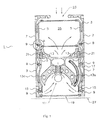
Figure 1 is a cross-sectional view of an ink curing apparatus constructed in accordance with the present invention; -
Figure 2 is an enlarged view of area A marked onFigure 1 showing the locking member; and -
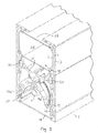
Figure 3 is a perspective view from the side of the ink curing apparatus ofFigure 1 . - Referring to
Figures 1 and3 , theapparatus 1 comprises a double-skinned housing 3. Thehousing 3 comprises aninner skin 5 and anouter wall 7, which are extruded separately. Theouter wall 7, in use, is locked to theinner skin 5 bymultiple locking members 9.Figure 1 shows thelocking members 9 in position andFigure 3 shows thehousing 3 without the locking members in place. As shown inFigure 2 , thelocking members 9 each compriseprotrusions inner skin 5 and theouter wall 7. Thelocking members 9 are shaped to allow longitudinal movement of theinner skin 5 within and along the length of theouter wall 7, whilst hallowing air to flow along the full length of theapparatus 1 in the channel between theouter wall 7 and theinner skin 5. -
Figure 1 shows threelocking members 9 along each side of thehousing 3. Twolocking members 9 secure the double walls of the lower section of thehousing 3 together and afurther locking member 9 secures the double wall of an upper section of the housing together. However, it is envisaged that the shape, number and positioning of thelocking members 9 can vary depending on the size of theapparatus 1. - The lower section of the
housing 3 is positioned in use over asubstrate 27. Thelower section 3 houses aUV lamp 11, partially surrounded by dichroic, coatedUV reflectors 13a, 13b andfurther UV reflectors 15. Thedichroic reflectors 13a, 13b are shaped to have fully elliptical geometry, which ensures that the highest possible peak power of UV radiation is retuned and directed towards thesubstrate 27 during the curing process. The reflector supports 15 are extruded separately from thechassis piece 13. Thereflectors 13a, 13b are made of an aluminium or glass material. Thereflectors 13a, 13b can be water-cooled or air cooled or, as shown in the embodiment ofFigure 1 , a combination of water-cooling and air-cooling is used. - A
moveable shutter 17 is rotatable around thelamp 11 at the lower end of theapparatus 1 to shield the substrate from theUV lamp 11 when theapparatus 1 is not in use. When theshutter 17 is in the closed position the inner surface of theshutter 17 overlaps the outer surface of each of thedichroic reflectors 13a, 13b. Aquartz window 19 is positioned below thehousing 3 and thelamp 11. In use asubstrate 27, which is to be cured, is placed below thequartz window 19. - The
inner skin 5 and theouter wall 5 are fixed together by thelocking members 9 with the channel created between them allowing for a free flow of air around theapparatus 1.Chassis sliders 21 are fixed to thechassis piece 13, as shown inFigure 1 . There aremultiple chassis sliders 21 along the length of thehousing 3. In use, thesliders 21 allow thelamp 11 and thechassis piece 13 withreflectors 13a, 13b to be removed, repaired and/or replaced for maintenance. When the required maintenance has been completed thechassis piece 13 can be easily and conveniently slid back into thehousing 3 along thechassis sliders 21. - The upper section of the
housing 3 comprises anopening 23, through which cooled, purged, filtered or ambient air enters theapparatus 1. The upper section also houses anair exhaust 25. - In use, a
substrate 27 carrying ink for curing/drying is transporter directly beneath thequartz window 19. Ultra-violet radiation from theUV lamp 11 is transmitted through thewindow 19 onto thesubstrate 27. Theshutter 17 is in an open position and thereflector 13a, 13b direct the UV light onto thesubstrate 27 for a period of time sufficient to cure/dry the ink on thesubstrate 27. - The
UV lamp 11 emits heat at around 850 degrees Celsius and a portion of this infra-red heat is absorbed by the surface of thereflectors 13a, 13b, and is then transmitted through the reflector supports 15. Heat is also absorbed by theinner skin 5 of thehousing 3, which will expand. When theinner skin 5 of thehousing 3 expands, themovable locking members 9 allows theinner skin 5 to move within theouter wall 7, along the length of thehousing 3. However, the lockingmembers 9 prevent transverse movement of theinner skin 5 towards or away from theouter wall 7 of thehousing 3. - As shown by the arrows in
Figure 1 , in order to cool the hot surfaces of theapparatus 1, cool ambient air is drawn in through theopening 23 in the upper section of thehousing 3 and pulled between theinner skin 5 and theouter wall 7 of thehousing 3. As the cool air reaches the surface of theUV lamp 11 and thereflectors dichroic reflectors 13 to theair exhaust 25. The hot air escapes from theapparatus 1 through theexhaust 25 taking with it a proportion of the heat created by thelamp 11. Thus, theapparatus 1 can be maintained at the desired operating temperature. - It is envisaged that, in alternative embodiments of the present invention, the
reflectors - The above described embodiment has been given by way of example only, and the skilled reader will naturally appreciate that many variations could be made thereto without departing from the scope of the claims.
Claims (9)
- A double-walled housing (3) for an ultra-violet ink curing apparatus (1), comprising an inner skin (5) and an outer wall (7) secured together by at least one locking means (9), wherein the or each locking means (9) is adapted to secure the inner skin (5) and the outer wall (7) together whilst permitting relative movement of the inner skin (5) along the length of the outer wall (7), characterised wherein
the or each locking means (9) prevents axial movement but allows longitudinal movement of the inner skin (5) with respect to the outer wall (7). - A housing (3) for an ultra-violet ink curing apparatus (1) according to claim 1 wherein the or each locking means (9) comprises at least one protrusion (9) adapted to mate with a corresponding recess in each of the inner skin (5) and the outer wall (7).
- A housing (3) for an ultra-violet ink curing apparatus (1) according to claim 2 wherein the at least one protrusion (9) is substantially cylindrical.
- A housing (3) for an ultra-violet ink curing apparatus (1) according to any preceding claim further comprising at least one cooling means.
- A housing (3) for an ultra-violet ink curing apparatus (1) according to claim 4 wherein the or each cooling means comprises at least one channel within the housing (3).
- A housing (3) for an ultra-violet ink curing apparatus (1) according to claim 5 wherein the or each channel is substantially parallel to the length of the housing (3).
- A housing (3) for an ultra-violet ink curing apparatus (1) according to claim 5 wherein the cooling means comprises at least one channel over or through the reflector surface (13a, 13b, 15) of the ink curing apparatus (1).
- An ultra-violet ink curing apparatus (1) comprising a housing (3) according to any preceding claim wherein the housing (3) comprises an upper section and a lower section, the lower section housing at least one UV lamp (11) and at least one reflector means (13a, 13b, 15) and wherein the lamp (11) and/or the reflector means (13a, 13b, 15) are removable from the UV apparatus (1) and separable from the upper section.
- An ultra-violet ink curing apparatus (1) according to claim 8 wherein the lamp (11) and/or the reflector means (13a, 13b, 15) are slideable with respect to the upper section of the apparatus (1).
Applications Claiming Priority (2)
| Application Number | Priority Date | Filing Date | Title |
|---|---|---|---|
| GB1113676.9A GB2495901B (en) | 2011-08-08 | 2011-08-08 | Improved housing for ink curing apparatus |
| PCT/GB2012/051898 WO2013021184A1 (en) | 2011-08-08 | 2012-08-06 | Improved housing for ink curing apparatus |
Publications (2)
| Publication Number | Publication Date |
|---|---|
| EP2697066A1 EP2697066A1 (en) | 2014-02-19 |
| EP2697066B1 true EP2697066B1 (en) | 2014-12-24 |
Family
ID=44735624
Family Applications (1)
| Application Number | Title | Priority Date | Filing Date |
|---|---|---|---|
| EP12754071.4A Active EP2697066B1 (en) | 2011-08-08 | 2012-08-06 | Improved housing for ink curing apparatus |
Country Status (5)
| Country | Link |
|---|---|
| US (1) | US9370941B2 (en) |
| EP (1) | EP2697066B1 (en) |
| ES (1) | ES2533330T3 (en) |
| GB (1) | GB2495901B (en) |
| WO (1) | WO2013021184A1 (en) |
Cited By (1)
| Publication number | Priority date | Publication date | Assignee | Title |
|---|---|---|---|---|
| WO2019201960A1 (en) * | 2018-04-20 | 2019-10-24 | Koenig & Bauer Ag | Processing machine comprising a radiation dryer and method for operating said dryer |
Families Citing this family (8)
| Publication number | Priority date | Publication date | Assignee | Title |
|---|---|---|---|---|
| CN103786430B (en) * | 2013-12-25 | 2016-08-31 | 陕西北人印刷机械有限责任公司 | A kind of energy-saving type hot air drying system and method |
| GB2525905A (en) | 2014-05-08 | 2015-11-11 | Gew Ec Ltd | Ink curing apparatus |
| GB201500494D0 (en) | 2015-01-13 | 2015-02-25 | Gew Ec Ltd | Print curing apparatus |
| JP6458588B2 (en) * | 2015-03-25 | 2019-01-30 | 株式会社Gsユアサ | Lamp cooling device and light irradiation device |
| US10209005B2 (en) | 2015-10-05 | 2019-02-19 | Sunlite Science & Technology, Inc. | UV LED systems and methods |
| US11000609B2 (en) * | 2017-03-23 | 2021-05-11 | Class 1 Inc. | Systems and apparatus for ultraviolet light disinfection |
| DE102018206152A1 (en) | 2018-04-20 | 2019-10-24 | Koenig & Bauer Ag | Drying device for a printing material processing machine and method for operating a drying device |
| CN108839432B (en) * | 2018-07-24 | 2023-05-19 | 成都市金雅迪彩色印刷有限公司 | High-efficiency paper drying device |
Family Cites Families (12)
| Publication number | Priority date | Publication date | Assignee | Title |
|---|---|---|---|---|
| GB1446167A (en) * | 1972-07-05 | 1976-08-18 | Wallace Knight Ltd | Lamp |
| GB2242259A (en) | 1990-03-22 | 1991-09-25 | Metal Box Plc | A lamp assembly |
| EP0985121B1 (en) * | 1997-05-26 | 2003-09-10 | Bernhard Max Glaus | Device for exposing a substrate to uv rays and method for using this device |
| GB2336895A (en) * | 1998-04-30 | 1999-11-03 | Gew | UV dryer with shaped reflector surface |
| DE19916474A1 (en) * | 1999-04-13 | 2000-10-26 | Ist Metz Gmbh | Radiation device |
| DE20114380U1 (en) * | 2001-08-31 | 2002-02-21 | Hoenle Ag Dr | UV irradiation device |
| US6883936B2 (en) * | 2002-10-15 | 2005-04-26 | Delaware Capital Formation, Inc. | Shutter apparatus, curing lamp housing incorporating same, and method of shutter replacement |
| GB2444328B (en) * | 2006-12-01 | 2010-06-09 | Gew | Cooling system for ink curing apparatus |
| EP1977895A1 (en) * | 2007-04-06 | 2008-10-08 | Komori Corporation | Drying apparatus for sheet |
| GB2468703A (en) * | 2009-03-19 | 2010-09-22 | Gew | Ink curing apparatus with water cooled heat exchanging means |
| JPWO2010150780A1 (en) * | 2009-06-26 | 2012-12-10 | Nkワークス株式会社 | Ultraviolet irradiation device and printing device |
| GB2495161B (en) * | 2012-02-28 | 2013-08-07 | Gew Ec Ltd | Ink curing apparatus |
-
2011
- 2011-08-08 GB GB1113676.9A patent/GB2495901B/en not_active Expired - Fee Related
-
2012
- 2012-08-06 ES ES12754071.4T patent/ES2533330T3/en active Active
- 2012-08-06 WO PCT/GB2012/051898 patent/WO2013021184A1/en active Application Filing
- 2012-08-06 EP EP12754071.4A patent/EP2697066B1/en active Active
- 2012-08-06 US US14/237,140 patent/US9370941B2/en active Active
Cited By (4)
| Publication number | Priority date | Publication date | Assignee | Title |
|---|---|---|---|---|
| WO2019201960A1 (en) * | 2018-04-20 | 2019-10-24 | Koenig & Bauer Ag | Processing machine comprising a radiation dryer and method for operating said dryer |
| US11046070B2 (en) | 2018-04-20 | 2021-06-29 | Koenig & Bauer Ag | Processing machine comprising a radiation dryer and method for operating said dryer |
| DE102018206154B4 (en) | 2018-04-20 | 2021-10-28 | Koenig & Bauer Ag | Drying device for a printing material processing machine and method for operating a drying device |
| EP4098447A1 (en) | 2018-04-20 | 2022-12-07 | Koenig & Bauer AG | Processing machine with a drying device and method for operating a drying device |
Also Published As
| Publication number | Publication date |
|---|---|
| GB201113676D0 (en) | 2011-09-21 |
| EP2697066A1 (en) | 2014-02-19 |
| WO2013021184A1 (en) | 2013-02-14 |
| ES2533330T3 (en) | 2015-04-09 |
| GB2495901A (en) | 2013-05-01 |
| US9370941B2 (en) | 2016-06-21 |
| US20140292970A1 (en) | 2014-10-02 |
| GB2495901B (en) | 2014-03-12 |
Similar Documents
| Publication | Publication Date | Title |
|---|---|---|
| EP2697066B1 (en) | Improved housing for ink curing apparatus | |
| EP2709849B1 (en) | Ink curing apparatus | |
| EP2454066B1 (en) | Method and device for blow-molding containers | |
| CN205450547U (en) | Colour wheel heat abstractor , light source module and projecting system | |
| EP2749397B1 (en) | Method and device for blow moulding containers | |
| CN105073658A (en) | Glass sheet support structure | |
| KR100864574B1 (en) | A printed matter drier for using a UV-lamp | |
| WO2010106338A1 (en) | Cooling system for ink curing apparatus | |
| US7686473B2 (en) | Lamp assembly | |
| JP2014181083A (en) | Image recording device | |
| EP2089228B1 (en) | Cooling system for ink curing apparatus | |
| JP6070312B2 (en) | Image recording device | |
| CN210171861U (en) | Camera curing device | |
| JP6036091B2 (en) | UV irradiator | |
| KR101433824B1 (en) | Pre-heating and post-heating apparatus for welding | |
| CN219616006U (en) | Drawer type curing oven and curing device | |
| KR101718537B1 (en) | A moving apparatus for induction heating coil assembly | |
| JP6525131B2 (en) | Replacement heat source unit, cooking device | |
| JP3214754U (en) | Hot air arbor heater | |
| CN217441528U (en) | LED automobile headlamp capable of effectively preventing high temperature | |
| WO2010106332A1 (en) | Improved housing for ink curing apparatus | |
| CN110884089A (en) | Bilateral heating system | |
| JP2011140195A (en) | Vulcanizer and method for manufacturing rubber member | |
| KR20090076373A (en) | A construction equipment | |
| JP2016207503A (en) | Cable covering crosslink method and cable covering crosslink device |
Legal Events
| Date | Code | Title | Description |
|---|---|---|---|
| PUAI | Public reference made under article 153(3) epc to a published international application that has entered the european phase |
Free format text: ORIGINAL CODE: 0009012 |
|
| 17P | Request for examination filed |
Effective date: 20131112 |
|
| AK | Designated contracting states |
Kind code of ref document: A1 Designated state(s): AL AT BE BG CH CY CZ DE DK EE ES FI FR GB GR HR HU IE IS IT LI LT LU LV MC MK MT NL NO PL PT RO RS SE SI SK SM TR |
|
| 17Q | First examination report despatched |
Effective date: 20140715 |
|
| GRAP | Despatch of communication of intention to grant a patent |
Free format text: ORIGINAL CODE: EPIDOSNIGR1 |
|
| DAX | Request for extension of the european patent (deleted) | ||
| INTG | Intention to grant announced |
Effective date: 20140819 |
|
| GRAS | Grant fee paid |
Free format text: ORIGINAL CODE: EPIDOSNIGR3 |
|
| GRAA | (expected) grant |
Free format text: ORIGINAL CODE: 0009210 |
|
| AK | Designated contracting states |
Kind code of ref document: B1 Designated state(s): AL AT BE BG CH CY CZ DE DK EE ES FI FR GB GR HR HU IE IS IT LI LT LU LV MC MK MT NL NO PL PT RO RS SE SI SK SM TR |
|
| REG | Reference to a national code |
Ref country code: GB Ref legal event code: FG4D |
|
| REG | Reference to a national code |
Ref country code: CH Ref legal event code: EP |
|
| REG | Reference to a national code |
Ref country code: IE Ref legal event code: FG4D |
|
| REG | Reference to a national code |
Ref country code: AT Ref legal event code: REF Ref document number: 702926 Country of ref document: AT Kind code of ref document: T Effective date: 20150115 |
|
| REG | Reference to a national code |
Ref country code: DE Ref legal event code: R096 Ref document number: 602012004553 Country of ref document: DE Effective date: 20150212 |
|
| REG | Reference to a national code |
Ref country code: ES Ref legal event code: FG2A Ref document number: 2533330 Country of ref document: ES Kind code of ref document: T3 Effective date: 20150409 |
|
| REG | Reference to a national code |
Ref country code: NL Ref legal event code: VDEP Effective date: 20141224 |
|
| PG25 | Lapsed in a contracting state [announced via postgrant information from national office to epo] |
Ref country code: LT Free format text: LAPSE BECAUSE OF FAILURE TO SUBMIT A TRANSLATION OF THE DESCRIPTION OR TO PAY THE FEE WITHIN THE PRESCRIBED TIME-LIMIT Effective date: 20141224 Ref country code: NO Free format text: LAPSE BECAUSE OF FAILURE TO SUBMIT A TRANSLATION OF THE DESCRIPTION OR TO PAY THE FEE WITHIN THE PRESCRIBED TIME-LIMIT Effective date: 20150324 Ref country code: FI Free format text: LAPSE BECAUSE OF FAILURE TO SUBMIT A TRANSLATION OF THE DESCRIPTION OR TO PAY THE FEE WITHIN THE PRESCRIBED TIME-LIMIT Effective date: 20141224 |
|
| REG | Reference to a national code |
Ref country code: LT Ref legal event code: MG4D |
|
| PG25 | Lapsed in a contracting state [announced via postgrant information from national office to epo] |
Ref country code: HR Free format text: LAPSE BECAUSE OF FAILURE TO SUBMIT A TRANSLATION OF THE DESCRIPTION OR TO PAY THE FEE WITHIN THE PRESCRIBED TIME-LIMIT Effective date: 20141224 Ref country code: LV Free format text: LAPSE BECAUSE OF FAILURE TO SUBMIT A TRANSLATION OF THE DESCRIPTION OR TO PAY THE FEE WITHIN THE PRESCRIBED TIME-LIMIT Effective date: 20141224 Ref country code: GR Free format text: LAPSE BECAUSE OF FAILURE TO SUBMIT A TRANSLATION OF THE DESCRIPTION OR TO PAY THE FEE WITHIN THE PRESCRIBED TIME-LIMIT Effective date: 20150325 Ref country code: SE Free format text: LAPSE BECAUSE OF FAILURE TO SUBMIT A TRANSLATION OF THE DESCRIPTION OR TO PAY THE FEE WITHIN THE PRESCRIBED TIME-LIMIT Effective date: 20141224 Ref country code: RS Free format text: LAPSE BECAUSE OF FAILURE TO SUBMIT A TRANSLATION OF THE DESCRIPTION OR TO PAY THE FEE WITHIN THE PRESCRIBED TIME-LIMIT Effective date: 20141224 |
|
| PG25 | Lapsed in a contracting state [announced via postgrant information from national office to epo] |
Ref country code: NL Free format text: LAPSE BECAUSE OF FAILURE TO SUBMIT A TRANSLATION OF THE DESCRIPTION OR TO PAY THE FEE WITHIN THE PRESCRIBED TIME-LIMIT Effective date: 20141224 |
|
| PG25 | Lapsed in a contracting state [announced via postgrant information from national office to epo] |
Ref country code: CZ Free format text: LAPSE BECAUSE OF FAILURE TO SUBMIT A TRANSLATION OF THE DESCRIPTION OR TO PAY THE FEE WITHIN THE PRESCRIBED TIME-LIMIT Effective date: 20141224 Ref country code: EE Free format text: LAPSE BECAUSE OF FAILURE TO SUBMIT A TRANSLATION OF THE DESCRIPTION OR TO PAY THE FEE WITHIN THE PRESCRIBED TIME-LIMIT Effective date: 20141224 Ref country code: RO Free format text: LAPSE BECAUSE OF FAILURE TO SUBMIT A TRANSLATION OF THE DESCRIPTION OR TO PAY THE FEE WITHIN THE PRESCRIBED TIME-LIMIT Effective date: 20141224 Ref country code: SK Free format text: LAPSE BECAUSE OF FAILURE TO SUBMIT A TRANSLATION OF THE DESCRIPTION OR TO PAY THE FEE WITHIN THE PRESCRIBED TIME-LIMIT Effective date: 20141224 |
|
| PG25 | Lapsed in a contracting state [announced via postgrant information from national office to epo] |
Ref country code: PL Free format text: LAPSE BECAUSE OF FAILURE TO SUBMIT A TRANSLATION OF THE DESCRIPTION OR TO PAY THE FEE WITHIN THE PRESCRIBED TIME-LIMIT Effective date: 20141224 Ref country code: IS Free format text: LAPSE BECAUSE OF FAILURE TO SUBMIT A TRANSLATION OF THE DESCRIPTION OR TO PAY THE FEE WITHIN THE PRESCRIBED TIME-LIMIT Effective date: 20150424 |
|
| REG | Reference to a national code |
Ref country code: DE Ref legal event code: R097 Ref document number: 602012004553 Country of ref document: DE |
|
| PG25 | Lapsed in a contracting state [announced via postgrant information from national office to epo] |
Ref country code: DK Free format text: LAPSE BECAUSE OF FAILURE TO SUBMIT A TRANSLATION OF THE DESCRIPTION OR TO PAY THE FEE WITHIN THE PRESCRIBED TIME-LIMIT Effective date: 20141224 |
|
| PLBE | No opposition filed within time limit |
Free format text: ORIGINAL CODE: 0009261 |
|
| STAA | Information on the status of an ep patent application or granted ep patent |
Free format text: STATUS: NO OPPOSITION FILED WITHIN TIME LIMIT |
|
| 26N | No opposition filed |
Effective date: 20150925 |
|
| REG | Reference to a national code |
Ref country code: AT Ref legal event code: UEP Ref document number: 702926 Country of ref document: AT Kind code of ref document: T Effective date: 20141224 |
|
| PG25 | Lapsed in a contracting state [announced via postgrant information from national office to epo] |
Ref country code: SI Free format text: LAPSE BECAUSE OF FAILURE TO SUBMIT A TRANSLATION OF THE DESCRIPTION OR TO PAY THE FEE WITHIN THE PRESCRIBED TIME-LIMIT Effective date: 20141224 |
|
| PG25 | Lapsed in a contracting state [announced via postgrant information from national office to epo] |
Ref country code: MC Free format text: LAPSE BECAUSE OF FAILURE TO SUBMIT A TRANSLATION OF THE DESCRIPTION OR TO PAY THE FEE WITHIN THE PRESCRIBED TIME-LIMIT Effective date: 20141224 Ref country code: LU Free format text: LAPSE BECAUSE OF FAILURE TO SUBMIT A TRANSLATION OF THE DESCRIPTION OR TO PAY THE FEE WITHIN THE PRESCRIBED TIME-LIMIT Effective date: 20150806 |
|
| PG25 | Lapsed in a contracting state [announced via postgrant information from national office to epo] |
Ref country code: BE Free format text: LAPSE BECAUSE OF FAILURE TO SUBMIT A TRANSLATION OF THE DESCRIPTION OR TO PAY THE FEE WITHIN THE PRESCRIBED TIME-LIMIT Effective date: 20141224 |
|
| REG | Reference to a national code |
Ref country code: IE Ref legal event code: MM4A |
|
| REG | Reference to a national code |
Ref country code: FR Ref legal event code: ST Effective date: 20160429 |
|
| PG25 | Lapsed in a contracting state [announced via postgrant information from national office to epo] |
Ref country code: IE Free format text: LAPSE BECAUSE OF NON-PAYMENT OF DUE FEES Effective date: 20150806 |
|
| PG25 | Lapsed in a contracting state [announced via postgrant information from national office to epo] |
Ref country code: FR Free format text: LAPSE BECAUSE OF NON-PAYMENT OF DUE FEES Effective date: 20150831 |
|
| PG25 | Lapsed in a contracting state [announced via postgrant information from national office to epo] |
Ref country code: MT Free format text: LAPSE BECAUSE OF FAILURE TO SUBMIT A TRANSLATION OF THE DESCRIPTION OR TO PAY THE FEE WITHIN THE PRESCRIBED TIME-LIMIT Effective date: 20141224 |
|
| PG25 | Lapsed in a contracting state [announced via postgrant information from national office to epo] |
Ref country code: BG Free format text: LAPSE BECAUSE OF FAILURE TO SUBMIT A TRANSLATION OF THE DESCRIPTION OR TO PAY THE FEE WITHIN THE PRESCRIBED TIME-LIMIT Effective date: 20141224 Ref country code: HU Free format text: LAPSE BECAUSE OF FAILURE TO SUBMIT A TRANSLATION OF THE DESCRIPTION OR TO PAY THE FEE WITHIN THE PRESCRIBED TIME-LIMIT; INVALID AB INITIO Effective date: 20120806 Ref country code: SM Free format text: LAPSE BECAUSE OF FAILURE TO SUBMIT A TRANSLATION OF THE DESCRIPTION OR TO PAY THE FEE WITHIN THE PRESCRIBED TIME-LIMIT Effective date: 20141224 |
|
| PG25 | Lapsed in a contracting state [announced via postgrant information from national office to epo] |
Ref country code: CY Free format text: LAPSE BECAUSE OF FAILURE TO SUBMIT A TRANSLATION OF THE DESCRIPTION OR TO PAY THE FEE WITHIN THE PRESCRIBED TIME-LIMIT Effective date: 20141224 |
|
| PG25 | Lapsed in a contracting state [announced via postgrant information from national office to epo] |
Ref country code: MK Free format text: LAPSE BECAUSE OF FAILURE TO SUBMIT A TRANSLATION OF THE DESCRIPTION OR TO PAY THE FEE WITHIN THE PRESCRIBED TIME-LIMIT Effective date: 20141224 Ref country code: TR Free format text: LAPSE BECAUSE OF FAILURE TO SUBMIT A TRANSLATION OF THE DESCRIPTION OR TO PAY THE FEE WITHIN THE PRESCRIBED TIME-LIMIT Effective date: 20141224 |
|
| PG25 | Lapsed in a contracting state [announced via postgrant information from national office to epo] |
Ref country code: PT Free format text: LAPSE BECAUSE OF FAILURE TO SUBMIT A TRANSLATION OF THE DESCRIPTION OR TO PAY THE FEE WITHIN THE PRESCRIBED TIME-LIMIT Effective date: 20141224 |
|
| PG25 | Lapsed in a contracting state [announced via postgrant information from national office to epo] |
Ref country code: AL Free format text: LAPSE BECAUSE OF FAILURE TO SUBMIT A TRANSLATION OF THE DESCRIPTION OR TO PAY THE FEE WITHIN THE PRESCRIBED TIME-LIMIT Effective date: 20141224 |
|
| P01 | Opt-out of the competence of the unified patent court (upc) registered |
Effective date: 20230523 |
|
| PGFP | Annual fee paid to national office [announced via postgrant information from national office to epo] |
Ref country code: IT Payment date: 20230822 Year of fee payment: 12 Ref country code: GB Payment date: 20230714 Year of fee payment: 12 Ref country code: CH Payment date: 20230902 Year of fee payment: 12 Ref country code: AT Payment date: 20230822 Year of fee payment: 12 |
|
| PGFP | Annual fee paid to national office [announced via postgrant information from national office to epo] |
Ref country code: DE Payment date: 20230821 Year of fee payment: 12 |
|
| PGFP | Annual fee paid to national office [announced via postgrant information from national office to epo] |
Ref country code: ES Payment date: 20231027 Year of fee payment: 12 |