EP2696205A1 - Microboard reader with cover lifter for microboards - Google Patents
Microboard reader with cover lifter for microboards Download PDFInfo
- Publication number
- EP2696205A1 EP2696205A1 EP20130178313 EP13178313A EP2696205A1 EP 2696205 A1 EP2696205 A1 EP 2696205A1 EP 20130178313 EP20130178313 EP 20130178313 EP 13178313 A EP13178313 A EP 13178313A EP 2696205 A1 EP2696205 A1 EP 2696205A1
- Authority
- EP
- European Patent Office
- Prior art keywords
- microplate
- lid
- reader
- housing
- support
- Prior art date
- Legal status (The legal status is an assumption and is not a legal conclusion. Google has not performed a legal analysis and makes no representation as to the accuracy of the status listed.)
- Granted
Links
- 238000000034 method Methods 0.000 claims abstract description 18
- 230000033001 locomotion Effects 0.000 claims description 44
- 230000003287 optical effect Effects 0.000 claims description 41
- 238000001514 detection method Methods 0.000 claims description 17
- 238000005259 measurement Methods 0.000 claims description 16
- 239000002184 metal Substances 0.000 claims description 16
- 229910052751 metal Inorganic materials 0.000 claims description 16
- 239000000463 material Substances 0.000 claims description 15
- XEEYBQQBJWHFJM-UHFFFAOYSA-N Iron Chemical compound [Fe] XEEYBQQBJWHFJM-UHFFFAOYSA-N 0.000 claims description 9
- 239000011888 foil Substances 0.000 claims description 9
- 239000000853 adhesive Substances 0.000 claims description 7
- 150000002739 metals Chemical class 0.000 claims description 7
- PXHVJJICTQNCMI-UHFFFAOYSA-N Nickel Chemical compound [Ni] PXHVJJICTQNCMI-UHFFFAOYSA-N 0.000 claims description 6
- 238000004020 luminiscence type Methods 0.000 claims description 5
- 229910045601 alloy Inorganic materials 0.000 claims description 4
- 239000000956 alloy Substances 0.000 claims description 4
- 238000006243 chemical reaction Methods 0.000 claims description 4
- 230000007774 longterm Effects 0.000 claims description 4
- 229910017052 cobalt Inorganic materials 0.000 claims description 3
- 239000010941 cobalt Substances 0.000 claims description 3
- GUTLYIVDDKVIGB-UHFFFAOYSA-N cobalt atom Chemical compound [Co] GUTLYIVDDKVIGB-UHFFFAOYSA-N 0.000 claims description 3
- 229910052742 iron Inorganic materials 0.000 claims description 3
- 229910052759 nickel Inorganic materials 0.000 claims description 3
- 239000003973 paint Substances 0.000 claims description 3
- 238000012360 testing method Methods 0.000 claims description 3
- 239000003153 chemical reaction reagent Substances 0.000 claims description 2
- 239000012634 fragment Substances 0.000 claims 1
- 238000012546 transfer Methods 0.000 description 15
- 239000000523 sample Substances 0.000 description 11
- 239000002313 adhesive film Substances 0.000 description 8
- 238000002474 experimental method Methods 0.000 description 6
- 238000006073 displacement reaction Methods 0.000 description 5
- 239000007789 gas Substances 0.000 description 5
- 241001136792 Alle Species 0.000 description 4
- 238000002835 absorbance Methods 0.000 description 4
- 230000008020 evaporation Effects 0.000 description 4
- 238000001704 evaporation Methods 0.000 description 4
- 230000005284 excitation Effects 0.000 description 4
- 239000007788 liquid Substances 0.000 description 4
- 230000008901 benefit Effects 0.000 description 3
- 238000004113 cell culture Methods 0.000 description 3
- 239000003795 chemical substances by application Substances 0.000 description 3
- CURLTUGMZLYLDI-UHFFFAOYSA-N Carbon dioxide Chemical compound O=C=O CURLTUGMZLYLDI-UHFFFAOYSA-N 0.000 description 2
- 238000010276 construction Methods 0.000 description 2
- 238000011156 evaluation Methods 0.000 description 2
- 238000012544 monitoring process Methods 0.000 description 2
- 241001295925 Gegenes Species 0.000 description 1
- 238000004458 analytical method Methods 0.000 description 1
- 238000013459 approach Methods 0.000 description 1
- QVGXLLKOCUKJST-UHFFFAOYSA-N atomic oxygen Chemical compound [O] QVGXLLKOCUKJST-UHFFFAOYSA-N 0.000 description 1
- 229910002092 carbon dioxide Inorganic materials 0.000 description 1
- 239000001569 carbon dioxide Substances 0.000 description 1
- 238000012864 cross contamination Methods 0.000 description 1
- 230000007812 deficiency Effects 0.000 description 1
- 230000001419 dependent effect Effects 0.000 description 1
- 230000008021 deposition Effects 0.000 description 1
- 239000003792 electrolyte Substances 0.000 description 1
- 239000000835 fiber Substances 0.000 description 1
- 238000002347 injection Methods 0.000 description 1
- 239000007924 injection Substances 0.000 description 1
- 229920002521 macromolecule Polymers 0.000 description 1
- 239000000696 magnetic material Substances 0.000 description 1
- 230000000873 masking effect Effects 0.000 description 1
- 229910001092 metal group alloy Inorganic materials 0.000 description 1
- 239000000203 mixture Substances 0.000 description 1
- 235000015097 nutrients Nutrition 0.000 description 1
- 239000005304 optical glass Substances 0.000 description 1
- 229910052760 oxygen Inorganic materials 0.000 description 1
- 239000001301 oxygen Substances 0.000 description 1
- 238000012545 processing Methods 0.000 description 1
- 230000002035 prolonged effect Effects 0.000 description 1
- 238000007789 sealing Methods 0.000 description 1
- 239000002689 soil Substances 0.000 description 1
- 239000007787 solid Substances 0.000 description 1
- 239000000243 solution Substances 0.000 description 1
- 230000002269 spontaneous effect Effects 0.000 description 1
- 239000000126 substance Substances 0.000 description 1
- 238000009834 vaporization Methods 0.000 description 1
- 230000008016 vaporization Effects 0.000 description 1
- 229910052727 yttrium Inorganic materials 0.000 description 1
Images


Classifications
-
- G—PHYSICS
- G01—MEASURING; TESTING
- G01N—INVESTIGATING OR ANALYSING MATERIALS BY DETERMINING THEIR CHEMICAL OR PHYSICAL PROPERTIES
- G01N37/00—Details not covered by any other group of this subclass
-
- G—PHYSICS
- G01—MEASURING; TESTING
- G01N—INVESTIGATING OR ANALYSING MATERIALS BY DETERMINING THEIR CHEMICAL OR PHYSICAL PROPERTIES
- G01N21/00—Investigating or analysing materials by the use of optical means, i.e. using sub-millimetre waves, infrared, visible or ultraviolet light
- G01N21/62—Systems in which the material investigated is excited whereby it emits light or causes a change in wavelength of the incident light
- G01N21/63—Systems in which the material investigated is excited whereby it emits light or causes a change in wavelength of the incident light optically excited
- G01N21/64—Fluorescence; Phosphorescence
- G01N21/6428—Measuring fluorescence of fluorescent products of reactions or of fluorochrome labelled reactive substances, e.g. measuring quenching effects, using measuring "optrodes"
-
- G—PHYSICS
- G01—MEASURING; TESTING
- G01N—INVESTIGATING OR ANALYSING MATERIALS BY DETERMINING THEIR CHEMICAL OR PHYSICAL PROPERTIES
- G01N21/00—Investigating or analysing materials by the use of optical means, i.e. using sub-millimetre waves, infrared, visible or ultraviolet light
-
- G—PHYSICS
- G01—MEASURING; TESTING
- G01N—INVESTIGATING OR ANALYSING MATERIALS BY DETERMINING THEIR CHEMICAL OR PHYSICAL PROPERTIES
- G01N35/00—Automatic analysis not limited to methods or materials provided for in any single one of groups G01N1/00 - G01N33/00; Handling materials therefor
-
- G—PHYSICS
- G01—MEASURING; TESTING
- G01N—INVESTIGATING OR ANALYSING MATERIALS BY DETERMINING THEIR CHEMICAL OR PHYSICAL PROPERTIES
- G01N35/00—Automatic analysis not limited to methods or materials provided for in any single one of groups G01N1/00 - G01N33/00; Handling materials therefor
- G01N35/02—Automatic analysis not limited to methods or materials provided for in any single one of groups G01N1/00 - G01N33/00; Handling materials therefor using a plurality of sample containers moved by a conveyor system past one or more treatment or analysis stations
- G01N35/028—Automatic analysis not limited to methods or materials provided for in any single one of groups G01N1/00 - G01N33/00; Handling materials therefor using a plurality of sample containers moved by a conveyor system past one or more treatment or analysis stations having reaction cells in the form of microtitration plates
-
- G—PHYSICS
- G01—MEASURING; TESTING
- G01N—INVESTIGATING OR ANALYSING MATERIALS BY DETERMINING THEIR CHEMICAL OR PHYSICAL PROPERTIES
- G01N35/00—Automatic analysis not limited to methods or materials provided for in any single one of groups G01N1/00 - G01N33/00; Handling materials therefor
- G01N35/02—Automatic analysis not limited to methods or materials provided for in any single one of groups G01N1/00 - G01N33/00; Handling materials therefor using a plurality of sample containers moved by a conveyor system past one or more treatment or analysis stations
- G01N35/04—Details of the conveyor system
-
- G—PHYSICS
- G01—MEASURING; TESTING
- G01N—INVESTIGATING OR ANALYSING MATERIALS BY DETERMINING THEIR CHEMICAL OR PHYSICAL PROPERTIES
- G01N35/00—Automatic analysis not limited to methods or materials provided for in any single one of groups G01N1/00 - G01N33/00; Handling materials therefor
- G01N2035/00178—Special arrangements of analysers
- G01N2035/00277—Special precautions to avoid contamination (e.g. enclosures, glove- boxes, sealed sample carriers, disposal of contaminated material)
- G01N2035/00287—Special precautions to avoid contamination (e.g. enclosures, glove- boxes, sealed sample carriers, disposal of contaminated material) movable lid/cover for sample or reaction tubes
-
- G—PHYSICS
- G01—MEASURING; TESTING
- G01N—INVESTIGATING OR ANALYSING MATERIALS BY DETERMINING THEIR CHEMICAL OR PHYSICAL PROPERTIES
- G01N35/00—Automatic analysis not limited to methods or materials provided for in any single one of groups G01N1/00 - G01N33/00; Handling materials therefor
- G01N35/02—Automatic analysis not limited to methods or materials provided for in any single one of groups G01N1/00 - G01N33/00; Handling materials therefor using a plurality of sample containers moved by a conveyor system past one or more treatment or analysis stations
- G01N35/04—Details of the conveyor system
- G01N2035/0401—Sample carriers, cuvettes or reaction vessels
- G01N2035/0403—Sample carriers with closing or sealing means
- G01N2035/0405—Sample carriers with closing or sealing means manipulating closing or opening means, e.g. stoppers, screw caps, lids or covers
-
- Y—GENERAL TAGGING OF NEW TECHNOLOGICAL DEVELOPMENTS; GENERAL TAGGING OF CROSS-SECTIONAL TECHNOLOGIES SPANNING OVER SEVERAL SECTIONS OF THE IPC; TECHNICAL SUBJECTS COVERED BY FORMER USPC CROSS-REFERENCE ART COLLECTIONS [XRACs] AND DIGESTS
- Y10—TECHNICAL SUBJECTS COVERED BY FORMER USPC
- Y10S—TECHNICAL SUBJECTS COVERED BY FORMER USPC CROSS-REFERENCE ART COLLECTIONS [XRACs] AND DIGESTS
- Y10S436/00—Chemistry: analytical and immunological testing
- Y10S436/807—Apparatus included in process claim, e.g. physical support structures
Definitions
- the invention relates to a Deckelabheber for microplates, which is installed in a microplate reader with at least one optical measuring / detecting device.
- microplates allow biological or biochemical experiments to be performed in which a large number of samples are processed in parallel.
- Microplate readers have proven themselves many times in the optical evaluation of test results obtained in microplates.
- microplates As a microplate in the context of the present invention, all multiwell plates are referred to, which have a plurality of wells or containers, which are arranged in an array. Specifically preferred microplates have at least approximately the mass and footprint of a SBS standard microplate as published by the American National Standards Institute (ANSI). For example, microplates whose wells are equipped with a round bottom, flat bottom or V-bottom are known. The wells may be designed as "normal wells" or as "deep wells”. Also frustoconical or truncated pyramidal wells are known per se.
- microplates with a wide variety of corrugations have in common that they have a normalized footprint, ie a standardized footprint, and that the axial spacing of the corrugations arranged in an array is also standardized, for example at 24-wells (4 ⁇ 6). Plates 18 mm, 96 mm (8 x 12) plates 9 mm, 384-well (16 x 24) plates 4.5 mm and 1536-well (32 x 48) plates 2.25 mm
- the height of a microplate may vary depending on Type vary greatly and is typically between 10.4 mm (eg 1536 V soil deep well plate) and 44 mm (eg 96 well Masterblock ® Greiner).
- microplates When biological or biochemical experiments are carried out in microplates over a prolonged period of time (during hours or even days) and / or elevated temperatures, often and typically evaporation occurs, resulting in a decrease in the volume and concentration of electrolytes and macromolecules until the solids dry Can lead samples. For this reason, the microplates are preferably processed in a separate incubator, wherein temperature and humidity are controlled so that no evaporation takes place.
- the disadvantage here is that the microplates for measurements manually between incubator and reader back and forth must be transferred.
- the document EP 1 192 995 A2 discloses a special sealable lid for standard microplates and a robotic gripper for holding the microplate and repeatedly removing and replacing this special lid.
- the lid exerts a spring pressure on the seal so that it seals against the microplate.
- this special lid construction of the robot gripper is designed to release the resilient parts of the lid and constructed quite complicated.
- this microplate reader comprises at least one optical measuring / detecting device, a housing, a microplate support and a moving unit.
- the moving unit is for moving the microplate seat out of the housing into which
- the microplate reader according to the invention is characterized in that it comprises an integrated cover holding device arranged inside the housing for lifting a microplate cover from a microplate positioned on the microplate support and for placing a microplate cover on a microplate, this cover holding device for moving the microplate cover and / or the microplate support is designed to move the microplate in each case in an at least approximately vertical direction.
- FIG. 1 shows a vertical section through a microplate reader 1 with extended movement unit 5 and microplate support 4, after manually or robotically positioning a covered microplate 8 on the microplate support 4.
- the microplate reader 1 comprises a controller 21 for monitoring and controlling the functions of the reader and the movement unit 5.
- the microplate reader 1 shown here comprises at least one optical measuring / detecting device 2.
- the microplate reader 1 also comprises a housing 3, a microplate seat 4 and a moving unit 5, wherein the moving unit 5 for moving the microplate seat 4 out of the housing 3 is formed into the housing 3 and within the housing 3 in at least one substantially horizontal direction.
- the housing 3 is preferably optically sealed from the environment.
- the housing can also be insulated with respect to the temperature, the gas composition and their relative humidity from the environment and thus formed as a climate chamber.
- This optical measuring / detection device 2 can also be referred to as a "measuring head” and fixed in place, ie immovably arranged, in which case the movement unit 5 is additionally designed to be vertically movable for focusing the optical measuring / detecting device 2.
- a further alternative comprises forming a height-adjustable optical measuring / detecting device 2 and a height-adjustable moving unit 5, and then focusing the optical measuring / detecting device 2 preferably with the measuring head 2 with a fine Z-drive equipped for focusing the optical measuring / detecting device t.
- the microplate reader 1 also comprises an integrated cover holding device 6 arranged inside the housing 3 for lifting a microplate cover 7 from a microplate 8 positioned on the microplate support 4 and for placing a microplate cover 7 on a microplate 8.
- the cover holding device 6 is designed to lift one Microplate cover 7 from a microplate 8 positioned on the microplate support 4, for holding this microplate cover 7 during the optical measurement of the microplate 8 and for placing the same microplate cover 7 on the same microplate 8.
- the lid holding device 6 is formed such that with it the microplate lid 7 can be stored during the measurement of the microplate 8 within the housing 3 of the microplate reader 1.
- the cover holding device 6 and / or the microplate support 4 may each be formed in an at least approximately vertical direction.
- the microplate lid 7 is lifted from the microplate 8 or the microplate 8 is lowered relative to the microplate lid 7.
- a third possibility is to move the microplate cover 7 and the microplate 8 apart.
- exemplary microplate reader 1 comprises a lid holding device 6, which is designed as a magnetic lifter 6 '.
- This lid holding device 6 comprises an array of permanent magnets 9.
- This lid holding device 6 is fastened here with bending-elastic or limp elements 22 on a carrying device 17.
- These flexurally elastic or limp elements 22 are (as shown) preferably mounted so that their mounting locations on the support device 17 are further apart than their mounting locations on the magnetic lifter 6 '. This arrangement automatically gives an effective self-centering of the magnetic lifter 6 'and also efficiently dampens its natural vibration.
- the support device 17 must be designed accordingly expansive.
- These flexurally elastic or limp elements 22 are preferably designed as metal-comprising lines or cords.
- the supporting device 17 shown is designed to be adjustable in height, with any movements are indicated in each case with a directional arrow and a "Z".
- the lid holding device 6 may comprise an electromagnetic array 10 (not shown) or a single, switchable permanent magnet 11 (see FIG. Fig. 10 ).
- each microplate lid 7 to be lifted and set up comprises magnetizable material 12.
- the magnetizable material 12 is selected from a group comprising self-adhesive metal foils, applied metallic paints, molded metallic splinters or metallic grains, as well as plastic-coated or back-injected metal plates or metal foils.
- the metals are preferably selected from the group comprising iron, nickel, cobalt and their alloys and alloys of these metals with non-magnetizable metals.
- the in Fig. 1 shown exemplary microplate reader 1 also comprises a substantially horizontally disposed optical axis 23 and a substantially vertically arranged detection axis 24.
- this microplate reader 1 Located on the optical axis 23 and above the movement unit 5 with the microplate overlay 4, this microplate reader 1 comprises a detection optics second ', a light source L and a first excitation optical system 2 ".
- this microplate reader 1 comprises a second excitation optical system 2"' which is arranged below the movement unit 5 with the microplate support 4 and on the detection axis 24.
- the measuring head 2, ie the optical measuring / detection device is arranged.
- the individual optical elements 2, 2 ', 2 ", 2"' are preferably connected to one another by means of optical glass fibers, which is schematically indicated here by dash-dotted lines (without necessarily indicating the best or actual connection path).
- a door 20 has been opened here in a downward opening.
- a laterally displaceable door 20 may be provided (not shown).
- This alternative arrangement of the open door 20 facilitates the picking up of a microplate to be processed from a transfer station 37 placed in front of the door 20 (cf. Fig. 11 ).
- This alternative arrangement of the open door 20 also facilitates dispensing an already processed microplate to this transfer station 37 placed in front of the door 20 (see FIG. Fig. 11 ).
- Another alternative arrangement of the open door is, for example, that the door 20 made as a flap retracts to open under the plate transport to open.
- the deposition of the microplate 8 on the microplate support 4 or the picking up of the microplate 8 from the microplate support 4 can also be done manually, as shown by a robot 18 equipped with gripper fingers 19.
- the lid holding device 6 can be designed as suction cup lifter 6 "(not shown) and comprises at least one suction cup 14 which can be connected to a vacuum source 13.
- This vacuum source 13 is preferably arranged in the housing 3 of the microplate reader 1, but it can for example, be arranged outside of the microplate reader 1 for reasons of space.
- the lid holding device 6 may be designed as a gripper 6 '"(not shown) and comprises at least two gripper fingers 15 for loading side surfaces 16 of a microplate lid 7.
- the lid holding device 6 is designed to carry out a lifting and lowering movement.
- the lid holding device 6 is arranged immovable immovable, but then the moving unit 5 must be designed to carry out a lifting and lowering movement of the microplate seat 4.
- the optical measuring / detection device 2 that is to say the measuring head 2 is arranged immovably in place. It is also preferable to form the moving unit 5 for performing movements of the microplate base 4 in the X, Y, and Z directions of a Cartesian coordinate system.
- a measuring method in which, between the lifting of the microplate cover 7 from the microplate 8 positioned on the microplate support 4 according to step c) and the optical measurement of the microplate 8 with the microplate cover 7 lifted off with the at least one optical measuring / detection device 2 according to step d), the samples in the wells 25 of the microplate 8 with Air and / or be contacted with a reagent for triggering luminescence or other reactions.
- the inventive lifting and reassembly of the microplate cover 7 inside the microplate reader 1 - possibly in combination with a designed as a climate chamber sample space inside the microplate reader 1 - allows performing long-term experiments and monitoring the long-term kinetics (eg growth) of cell cultures in the wells 25 of microplates 8.
- the sporadically and repeatedly performed optical measurements on the samples are made possible by a brief lifting and reassembly of the microplate lid 7.
- adding nutrient medium or other substances and agents to the cell cultures in the wells 25 of microplates 8 is facilitated by briefly lifting and replacing the microplate lid 7.
- Such long-term tests are preferably carried out in standalone microplate readers 1.
- the microplate lid 7 after the optical measurement of the microplate 8 using the lid holding device 6 within the housing 3 of the microplate reader 1 placed on the microplate 8 and the microplate overlay 4 and the covered microplate 8 with the movement unit. 5 is conveyed out of the housing 3 of the microplate reader 1.
- this displacement problem can be solved by using an array of permanent magnets 9 instead of the single magnet (as shown).
- this displacement problem can be solved by the fact that the individual magnet of the magnetic lifter 6 'and the magnetizable material 12 are mounted exactly in projection one above the other.
- the cover holding device 6 instead of a magnetic lifter 6 'a plate of a magnetizable material (eg, iron, nickel or cobalt or from at least one of these metals comprehensive metal alloy), said plate preferably has a surface which is larger than the surface of the male microplate cover 7 (not shown). It then suffices for example to fasten a magnetic material (eg a magnetic foil or a single one) Permanent magnet) on the microplate cover (not shown).
- the lid holding device 6 may comprise a magnetizable material 12 selected from a group comprising self-adhering metal foils, applied metallic paints, molded metallic chips or grains, as well as plastic-molded or back-injected metal plates or metal foils.
- FIG. 10 shows a 3D view of the moving unit 5 with a microplate 8 positioned on the microplate support 4 with the microplate cover 7 mounted with side surfaces 16 and a magnetizable material 12.
- the Cartesian coordinate system is indicated by the three arrows (X, Y and Z).
- the movement unit 5 comprises two parallel guide rods 27 on each of which a sliding bearing 30 is movably arranged. These two plain bearings 30 are connected to each other via a carriage 36.
- a first motor 26 moves this carriage 36 in an X direction of a Cartesian coordinate system with a first toothed belt guided over a first guide roller 29.
- the microplate support 4 is attached to this carriage 36 by means of a link 33, said link 33 being movably guided along a linear guide 32 and along the carriage 36.
- a second motor 31 moves the link 33 with the microplate rest 4 in a Y direction of the Cartesian coordinate system by means of a second toothed belt 34 guided via a second deflecting roller 35.
- the moving device 5 just described is preferably movable in a Z direction of the Cartesian coordinate system (not shown) in Fig. 10 ).
- FIG. 10 also shows a lid holding device 6 with a magnetic lifter 6 ', which comprises a single, switchable permanent magnet 11.
- Switchable permanent magnets are known from the prior art (cf., for example EP 0 114 259 B1 ) and are adapted by a person skilled in the knowledge of the present invention in their construction and arrangement the requirements for lifting a microplate cover 7.
- lid holding device 6 instead of the lid holding device 6 with a magnetic lifter 6 ', a person skilled in the art could readily provide a lid holding device 6 which is designed as a suction cup lifter 6 "or as a gripper 6'", wherein it requires a raising and lowering motion as needed the lid holding device 6 would coordinate with movements of the moving unit 5 to perform movements of the microplate rest 4 in the X, Y, and Z directions of a Cartesian coordinate system.
- FIG. 11 shows a slightly enlarged 3D view of the empty microplate support 4 of the movement unit 5 (corresponding to the Fig. 10 ) at a transfer station 37 and in the corresponding magnification, a 3D view of a 96-well microplate 8 without microplate lid 7.
- the transfer station 37 comprises a support plate 38 with a microplate 4 adapted shape, wherein the microplate support 4 has cutouts 39 which extend beyond the Footprint 40 a standard microplate 8 go out, so that parts of the support plate 38, which extend into these cutouts 39 enough to support the microplate 8 suffice.
- the microplate receptacle 4 of the movement unit 5 is extended at a Z level below the level of the support plate 38 of the transfer station 37 and thus also below the footprint 40 of the microplate 8 on this support plate 38.
- the microplate holder 4 is raised in the Z direction until the microplate 8 lies on the microplate holder 4.
- the large section 39 in the support plate 38 very low in the FIG. 11 ) starting the transfer station 37 at a lower level than the surface of the support plate, if this support plate 38 by a central post (not shown) on a working surface of a laboratory workstation (not shown) should be supported.
- the microplate receptacle 4 of the movement unit 5 is extended in a Z-level which is above the level of the support plate 38 of the transfer station 37. After taking a correct transfer position, the microplate receptacle 4 is lowered in the Z direction until the microplate 8 lies on the support plate 38 of the transfer station 37.
Abstract
Description
Die Erfindung betrifft einen Deckelabheber für Mikroplatten, der in einen Mikroplatten-Reader mit mindestens einer optischen Mess-/Detektions-Einrichtung eingebaut ist. Mikroplatten erlauben beispielsweise das Durchführen von biologischen oder biochemischen Versuchen, bei welchen eine grosse Anzahl von Proben parallel bearbeitet wird. Mikroplatten-Reader haben sich bei der optischen Auswertung von in Mikroplatten erzielten Versuchsresultaten vielfach bewährt.The invention relates to a Deckelabheber for microplates, which is installed in a microplate reader with at least one optical measuring / detecting device. For example, microplates allow biological or biochemical experiments to be performed in which a large number of samples are processed in parallel. Microplate readers have proven themselves many times in the optical evaluation of test results obtained in microplates.
Als Mikroplatte werden im Zusammenhang mit der vorliegenden Erfindung alle Multiwellplatten bezeichnet, die eine Vielzahl an Wells oder Behälter aufweisen, welche in einem Array angeordnet sind. Speziell bevorzugte Mikroplatten weisen zumindest annähernd die Masse und den Footprint einer Mikroplatte nach dem SBS Standard auf, wie dieser vom American National Standards Institute (ANSI) veröffentlicht wurde. Bekannt sind beispielsweise Mikroplatten, deren Wells mit einem Rundboden, Flachboden oder V-Boden ausgestattet sind. Dabei können die Wells als "normale Wells" oder auch als "Deep Wells" ausgebildet sein. Auch kegelstumpf- oder pyramidenstumpfförmige Wells sind an sich bekannt. Allen Mikroplatten mit den unterschiedlichsten Wellformen ist gemeinsam, dass sie eine normierte Grundfläche, also einen normierten Footprint" aufweisen, und dass der Achsabstand der jeweils in einem Array angeordneten Wells ebenfalls normiert ist. Dieser Achsabstand beträgt z.B. bei 24-Well (4 x 6) Platten 18 mm, bei 96-Well (8 x 12) Platten 9 mm, bei 384-Well (16 x 24) Platten 4.5 mm und bei 1536-Well (32 x 48) Platten 2.25 mm. Die Höhe einer Mikroplatte kann je nach Typ sehr stark variieren und beträgt typischerweise zwischen 10.4 mm (z.B. 1536 V-Boden Deep Well Platte) und 44 mm (z.B. 96 Well Masterblock® von Greiner).As a microplate in the context of the present invention, all multiwell plates are referred to, which have a plurality of wells or containers, which are arranged in an array. Specifically preferred microplates have at least approximately the mass and footprint of a SBS standard microplate as published by the American National Standards Institute (ANSI). For example, microplates whose wells are equipped with a round bottom, flat bottom or V-bottom are known. The wells may be designed as "normal wells" or as "deep wells". Also frustoconical or truncated pyramidal wells are known per se. All microplates with a wide variety of corrugations have in common that they have a normalized footprint, ie a standardized footprint, and that the axial spacing of the corrugations arranged in an array is also standardized, for example at 24-wells (4 × 6).
Werden biologische oder biochemische Versuche in Mikroplatten über eine längere Zeitdauer (während Stunden oder gar Tagen) und/oder bei gegenüber der Raumtemperatur erhöhten Temperaturen durchgeführt, tritt oft und typischerweise Verdunstung auf, die zu einer Volumenabnahme und Konzentrationsveränderung von Elektrolyten und Makromolekülen bis zum Eintrocknen der Proben führen kann. Aus diesem Grund werden die Mikroplatten vorzugsweise in einem separaten Inkubator prozessiert, wobei Temperatur und Luftfeuchte so geregelt sind, dass keine Verdunstung stattfindet. Nachteilig ist dabei, dass die Mikroplatten für Messungen händisch zwischen Inkubator und Reader hin- und her transferiert werden müssen. Diese Erörterung bezieht sich auf den Betrieb als Standalone-Reader; ist der Reader hingegen Teil eines Robotiksystems (Grössere Laboranlagen, insbesondere automatisierte Laborsysteme, umfassen meistens einen Roboter, der üblicherweise mit Pipettenspitzen für den Transport von Flüssigkeiten oder mit Greifern für den Transport von Labware wie z.B. Mikroplatten oder Probenröhrchen versehen ist. Als ein Beispiel für ein derartiges Laborsystem sei die Freedom EVO® Liquid Handling Workstation des aktuellen Anmelders genannt), so übernimmt der Roboter dieses Systems den Transfer zwischen Reader und Mehrfach-Inkubator. Alternativ könnten die Mikroplatten im Reader selbst prozessiert werden mit dem Vorteil, dass zwischendurch und automatisch Messzyklen durchgeführt werden können. Es wäre jedoch in einem Robotersystem nachteilig, einen Reader mit einer einzigen Mikroplatte für Tage zu blockieren.When biological or biochemical experiments are carried out in microplates over a prolonged period of time (during hours or even days) and / or elevated temperatures, often and typically evaporation occurs, resulting in a decrease in the volume and concentration of electrolytes and macromolecules until the solids dry Can lead samples. For this reason, the microplates are preferably processed in a separate incubator, wherein temperature and humidity are controlled so that no evaporation takes place. The disadvantage here is that the microplates for measurements manually between incubator and reader back and forth must be transferred. This discussion refers to the operation as a standalone reader; however, the reader is part of a robotic system (Larger lab equipment, particularly automated laboratory systems, usually includes a robot that is typically provided with pipette tips for transporting liquids or grippers for transporting labware such as microplates or sample tubes such a laboratory system is called the Freedom EVO® liquid handling workstation of the current applicant), the robot of this system takes over the transfer between reader and multiple incubator. Alternatively, the microplates could be processed in the reader itself, with the advantage that measurement cycles can be performed in between and automatically. However, it would be disadvantageous in a robotic system to block a reader with a single microplate for days.
Standardmässig wird das Verdunsten von Probenflüssigkeit aus Mikroplatten dadurch bekämpft, dass die Mikroplatte mit einem Deckel abgedeckt wird, oder dass die Mikroplatte bzw. deren Wells mit selbstklebenden oder auflaminierten Folien verschlossen werden. Ein solches Abdecken oder Verschliessen bringt einige Nachteile mit sich, wie z.B.:
- die Verwendung eines robotisierten Injektors zum Zugeben von Agenzien in die Wells (z.B. zum Auslösen von Lumineszenzreaktionen in den Proben) ist nicht möglich;
- das Abdecken verringert die Gaszufuhr aus der Umgebung in die Wells, wodurch ein Sauerstoff- und/oder Kohlendioxid-Mangel in den Wells resultiert, der je nach Zelltyp das Wachstum der Zellen verlangsamt, die Prozessierungszeit verlängert und die maximal erreichbaren Zellkonzentrationen verringert;
- der Gasaustausch zwischen den Proben in den Wells und der Umgebung ist reduziert oder verunmöglicht, so dass sich unter Umständen schädliche Gaskonzentrationen im Luftraum der Wells über den Proben (z.B. bei Zellkulturen oder zellbasierten Versuchen) bilden können;
- aus den Proben verdunstete Flüssigkeit kann an der Unterseite des Deckels oder der Selbstklebefolie kondensieren, so dass der dadurch entstehende Beschlag zu fehlerhaften optischen Messungen (z.B. der Absorbance) führt;
- der Deckel und die Selbstklebefolie verhindern oder zumindest behindern das optische Erfassen von Fluoreszenz in den Proben mittels der bevorzugten Top-Detektion (also von oben);
- der Deckel und die Selbstklebefolie verunmöglichen das optische Erfassen von Lumineszenz in den Proben mittels Top-Detektion.
- the use of a robotized injector to add agents into the wells (eg to trigger luminescent reactions in the samples) is not possible;
- capping reduces the gas supply from the environment to the wells, resulting in oxygen and / or carbon dioxide deficiency in the wells, which, depending on the cell type, slows down the growth of the cells, prolongs the processing time and reduces the maximum achievable cell concentrations;
- the gas exchange between the samples in the wells and the environment is reduced or made impossible, so that possibly harmful gas concentrations in the air space of the wells can form above the samples (eg in cell cultures or cell-based experiments);
- liquid evaporated from the samples may condense on the underside of the lid or self-adhesive film, resulting in mistaken optical measurements (eg absorbance);
- the lid and the self-adhesive foil prevent or at least hinder the optical detection of fluorescence in the samples by means of the preferred top detection (ie from above);
- The lid and the self-adhesive film make it impossible to optically detect luminescence in the samples by means of top detection.
Bisher wurde solchen Problemen wenigstens teilweise begegnet, indem vor dem Einlegen einer Mikroplatte in den Mikroplatten-Reader der Deckel oder die Selbstklebefolie entfernt und nach dem Beenden des Ausmessens bzw. der optischen Auswertung der Platte im Reader der Deckel oder die Selbstklebefolie wieder montiert wurde. Es versteht sich von selbst, dass derartige Manipulationen an mit heiklen Proben beschickten Mikroplatten umständlich und für die Proben möglicherweise sogar extrem schädlich sein können. Insbesondere können sich beim Wiedermontieren von bereits verwendeten Selbstklebefolien Kreuzkontaminationen ergeben. Dies ist insbesondere dann der Fall, wenn im Verlauf eines mehrtägigen Versuchsprotokolls dieselbe Mikroplatte mehrmals und zu unterschiedlichen Zeiten im Mikroplatten-Reader untersucht werden soll, auch sind Unfälle auf dem Weg zwischen dem Ort des Abnehmens des Deckels oder der Selbstklebefolie und dem Ort des Mikroplatten-Readers nicht ausgeschlossen.So far, such problems have been at least partially met by removing before inserting a microplate in the microplate reader, the lid or the self-adhesive film and after completing the measurement or the optical evaluation of the plate in the reader, the lid or the self-adhesive film was reassembled. It goes without saying that such manipulations on microplates loaded with sensitive samples may be cumbersome and possibly even extremely damaging to the samples. In particular, cross-contamination may result when reassembling already used self-adhesive films. This is particularly the case when, in the course of a multi-day trial protocol, the same microplate is to be examined several times and at different times in the microplate reader, also accidents are on the way between the place of removal of the lid or the self-adhesive film and the location of the microplate reader. Readers not excluded.
Lösungen zum robotisierten Abnehmen von Mikroplattendeckeln sind aus dem Stand der Technik bekannt:
- Das Dokument
US 2011/0293488 A1
- The document
US 2011/0293488 A1
Das Dokument
Das Dokument
Das Dokument
Auch wenn teilweise die Möglichkeit offenbart wurde Standardmikroplatten und eventuell sogar Standardmikroplattendeckel zu verwenden, so bieten alle bekannten Dokumente aus dem Stand der Technik keine Lösung für das Problem des oft heiklen Wegs der Mikroplatte (und insbesondere der ungedeckten Proben) für die zeit zwischen dem Deckelabheben und der optischen Analyse der Proben im Mikroplatten-Reader.Although some have disclosed the possibility of using standard microdisks and possibly even standard microdisks, all known prior art documents do not solve the problem of the often delicate path of the microplate (and in particular the uncovered samples) between the time the lid is lifted and the optical analysis of the samples in the microplate reader.
Es ist deshalb eine Aufgabe der vorliegenden Erfindung, eine alternative Vorrichtung und ein alternatives Verfahren vorzuschlagen, das die aus dem Stand der Technik bekannten Nachteile eliminiert.It is therefore an object of the present invention to propose an alternative apparatus and method that eliminates the disadvantages known from the prior art.
Diese Aufgabe wird gemäss einem ersten Aspekt mit einem Mikroplatten-Reader entsprechend den Merkmalen des unabhängigen Anspruchs 1 gelöst. Dabei umfasst dieser Mikroplatten-Reader mindestens eine optische Mess-/Detektions-Einrichtung, ein Gehäuse, eine Mikroplattenauflage und eine Bewegungseinheit. Die Bewegungseinheit ist zum Bewegen der Mikroplattenauflage aus dem Gehäuse heraus, in dasThis object is achieved according to a first aspect with a microplate reader according to the features of
Gehäuse hinein und innerhalb des Gehäuses in zumindest einer im Wesentlichen horizontalen Richtung ausgebildet. Der erfindungsgemässe Mikroplatten-Reader ist dadurch gekennzeichnet, dass er eine integrierte, innerhalb des Gehäuses angeordnete Deckelhaltevorrichtung zum Abheben eines Mikroplattendeckels von einer auf der Mikroplattenauflage positionierten Mikroplatte und zum Auflegen eines Mikroplattendeckels auf eine Mikroplatte umfasst, wobei diese Deckelhaltevorrichtung zur Bewegung des Mikroplattendeckels und/oder die Mikroplattenauflage zur Bewegung der Mikroplatte in jeweils einer zumindest annähernd vertikalen Richtung ausgebildet sind.Housing formed inside and inside the housing in at least one substantially horizontal direction. The microplate reader according to the invention is characterized in that it comprises an integrated cover holding device arranged inside the housing for lifting a microplate cover from a microplate positioned on the microplate support and for placing a microplate cover on a microplate, this cover holding device for moving the microplate cover and / or the microplate support is designed to move the microplate in each case in an at least approximately vertical direction.
Diese Aufgabe wird gemäss einem zweiten Aspekt mit einem Verfahren zum optischen Ausmessen von Proben in Wells einer mit einem Mikroplattendeckel versehenen Mikroplatte in einem derartigen Mikroplatten-Reader entsprechend den Merkmalen des unabhängigen Anspruchs 15 gelöst. Das erfindungsgemässe Messverfahren umfasst dabei die folgenden Schritte:
- (a) Platzieren einer mit einem Mikroplattendeckel abgedeckten Mikroplatte auf der Mikroplattenauflage des Mikroplatten-Readers;
- (b) Einziehen der Mikroplattenauflage und der abgedeckten Mikroplatte mit der Bewegungseinheit in das Gehäuse des Mikroplatten-Readers;
- (c) Abheben des Mikroplattendeckels von der auf der Mikroplattenauflage positionierten Mikroplatte mit einer im Mikroplatten-Reader integrierten und innerhalb des Gehäuses angeordnete Deckelhaltevorrichtung;
- (d) Ausmessen der Mikroplatte der Mikroplatte mit abgehobenem Mikroplattendeckel mit der mindestens einen optischen Mess-/Detektions-Einrichtung;
- (e) Wiederauflegen des Mikroplattendeckels auf der auf der Mikroplattenauflage positionierten Mikroplatte unter Verwendung der im Mikroplatten-Reader integrierten Deckelhaltevorrichtung; und
- (f) Ausfahren der Mikroplattenauflage und der abgedeckten Mikroplatte mit der Bewegungseinheit aus dem Gehäuse des Mikroplatten-Readers.
- (a) placing a microplate cover covered with a microplate cover on the microplate support of the microplate reader;
- (b) drawing the microplate overlay and the covered microplate with the moving unit into the housing of the microplate reader;
- (c) lifting the microplate lid from the microplate positioned on the microplate overlay with a lid retainer integrated within the microplate reader and disposed within the housing;
- (d) measuring the microplate of the microplate lifted-off microplate lid with the at least one optical measuring / detecting means;
- (e) reloading the microplate lid onto the microplate positioned on the microplate overlay using the lidmounting device integrated in the microplate reader; and
- (f) Extending the microplate overlay and the covered microplate with the moving unit from the microplate reader housing.
Weitere bevorzugte und erfinderische Merkmale ergeben sich aus den jeweils abhängigen Ansprüchen.Further preferred and inventive features emerge from the respective dependent claims.
Vorteile des erfindungsgemässen Mikroplatten-Readers bzw. des erfindungsgemässen Messverfahrens umfassen:
- Alle bekannten Messmodi (z.B. Absorbance, Fluoreszenz, Lumineszenz) können an deckellosen bzw. abgedeckten Mikroplatten angewendet werden, während ausserhalb der Messzeiten die Mikroplatte mit einem Deckel abgedeckt werden kann;
- Es können Standard-Mikroplatten und (eventuell geringfügig modifizierte) Standard-Mikroplattendeckel verwendet werden;
- Bei Zellbasierten Versuchen kann der Verdunstungsschutz durch Abdecken mit dem Anbieten von genügendem Gasaustausch durch kurzzeitiges Abdecken der Mikroplatten kombiniert werden;
- Das automatisierte Injizieren von (z.B. Lumineszenz oder anderen Reaktionen auslösenden) Agenzien ist währen des Durchführens von Versuchen in deckelgeschützten Mikroplatten möglich.
- All known measurement modes (eg absorbance, fluorescence, luminescence) can be applied to coverless or covered microplates, while outside the measurement times the microplate can be covered with a lid;
- Standard microplates and (possibly slightly modified) standard microplate lids may be used;
- In cell-based experiments, the evaporation protection can be combined by capping with the provision of sufficient gas exchange by briefly covering the microplates;
- The automated injection of (eg, luminescence or other reaction triggering) agents is possible while conducting experiments in cover-protected microplates.
Ein beispielhafter erfindungsgemässer Mikroplatten-Reader wird anhand von schematischen Skizzen gezeigt. Diese Skizzen sollen ausgewählte Ausführungsformen des erfindungsgemässen Mikroplatten-Readers dokumentieren, aber den Umfang der vorliegenden Erfindung nicht einschränken. Dabei zeigt:
- Fig. 1
- einen Vertikalschnitt durch einen Mikroplatten-Reader mit ausgefahrener Bewegungseinheit und Mikroplattenauflage, nach dem manuellen oder robotisierten Positionieren einer abgedeckten Mikroplatte auf der Mikroplattenauflage;
- Fig. 2
- einen Vertikalschnitt durch einen Mikroplatten-Reader mit eingefahrener Bewegungseinheit und Mikroplattenauflage, vor dem Abheben des Mikroplattendeckels mit einer integrierten Deckelhaltevorrichtung;
- Fig. 3
- einen Vertikalschnitt durch einen Mikroplatten-Reader mit eingefahrener Bewegungseinheit und Mikroplattenauflage, beim Abheben des Mikroplattendeckels mit einem Magnetheber der integrierten Deckelhaltevorrichtung;
- Fig. 4
- einen Vertikalschnitt durch einen Mikroplatten-Reader mit eingefahrener Bewegungseinheit und Mikroplattenauflage; die Mikroplatte mit abgehobenem Mikroplattendeckel ist bereit zum Messen;
- Fig. 5
- einen Vertikalschnitt durch einen Mikroplatten-Reader mit eingefahrener Bewegungseinheit und Mikroplattenauflage beim optischen Ausmessen der Mikroplatte mit abgehobenem Mikroplattendeckel und mit korrigiertem Arbeitsabstand zur Mess-/Detektions-Einrichtung;
- Fig. 6
- einen Vertikalschnitt durch einen Mikroplatten-Reader mit eingefahrener Bewegungseinheit und Mikroplattenauflage beim Auflegen des Mikroplattendeckels auf die Mikroplatte;
- Fig. 7
- einen Vertikalschnitt durch einen Mikroplatten-Reader mit eingefahrener Bewegungseinheit und Mikroplattenauflage beim Wegbewegen der wieder abgedeckten Mikroplatte vom Magnetheber der integrierten Deckelhaltevorrichtung;
- Fig. 8
- einen Vertikalschnitt durch einen Mikroplatten-Reader mit ausgefahrener Bewegungseinheit und Mikroplattenauflage, beim manuellen oder robotisierten Wegnehmen der wieder abgedeckten Mikroplatte von der Mikroplattenauflage;
- Fig. 9
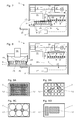
- Aufsichten auf mit selbstklebender Eisenfolie modifizierte Standard-Mikroplattendeckel, wobei
- Fig. 9A
- zwei schmale, querliegende und extrem positionierte Streifen auf dem Deckel für eine 96-Well Mikroplatte;
- Fig. 9B
- zwei willkürlich platzierte, zumindest annähernd dreieckige Stücke auf dem Deckel für eine 24-Well Mikroplatte;
- Fig. 9C
- zwei willkürlich zwischen den Wells platzierte, zumindest annähernd quadratische Stücke auf dem Deckel für eine 6-Well Mikroplatte; und
- Fig. 9D
- zwei Alternativen von zumindest annähernd rechteckigen Stücken auf dem Deckel für eine beliebige Standard-Mikroplatte zeigt;
- Fig. 10
- eine 3D-Ansicht der Bewegungseinheit mit auf der Mikroplattenauflage positionierter Mikroplatte mit aufgesetztem Mikroplattendeckel;
- Fig. 11
- eine leicht vergrösserte 3D-Ansicht der leeren Mikroplattenauflage der Bewegungseinheit bei einer Übergabestation und in der entsprechenden Vergrösserung eine 3D-Ansicht einer 96-Well Mikroplatte ohne Mikroplattendeckel.
- Fig. 1
- a vertical section through a microplate reader with extended movement unit and microplate support, after manually or robotically positioning a covered microplate on the microplate support;
- Fig. 2
- a vertical section through a microplate reader with retracted motion unit and microplate support, before lifting the microplate lid with an integrated lid holding device;
- Fig. 3
- a vertical section through a microplate reader with retracted motion unit and microplate support, when lifting the microplate lid with a magnetic lifter integrated lid holding device;
- Fig. 4
- a vertical section through a microplate reader with retracted motion unit and microplate support; the microplate with the microplate lid lifted is ready to be measured;
- Fig. 5
- a vertical section through a microplate reader with retracted motion unit and microplate support in optically measuring the microplate with lifted microplate lid and with corrected working distance to the measuring / detecting device;
- Fig. 6
- a vertical section through a microplate reader with retracted motion unit and microplate support when placing the microplate lid on the microplate;
- Fig. 7
- a vertical section through a microplate reader with retracted motion unit and microplate support while moving the re-covered microplate of the magnetic lifter of the integrated lid holding device;
- Fig. 8
- a vertical section through a microplate reader with extended movement unit and microplate support, the manual or robotic removal of the re-covered microplate of the microplate support;
- Fig. 9
- Top views on self-adhesive iron foil modified standard microplate lid, wherein
- Fig. 9A
- two narrow, transverse and extremely positioned strips on the lid for a 96-well microplate;
- Fig. 9B
- two arbitrarily placed, at least approximately triangular, pieces on the lid for a 24-well microplate;
- Fig. 9C
- two arbitrarily placed between the wells, at least approximately square pieces on the lid for a 6-well microplate; and
- Fig. 9D
- shows two alternatives of at least approximately rectangular pieces on the lid for any standard microplate;
- Fig. 10
- a 3D view of the moving unit with microplate positioned on the microplate support with the microplate cover attached;
- Fig. 11
- a slightly enlarged 3D view of the empty microplate overlay of the moving unit at a transfer station and in the corresponding magnification a 3D view of a 96-well microplate without microplate lid.
Die
Der hier gezeigte Mikroplatten-Reader 1 umfasst mindestens eine optische Mess-/ Detektions-Einrichtung 2. Der Mikroplatten-Reader 1 umfasst zudem ein Gehäuse 3, eine Mikroplattenauflage 4 und eine Bewegungseinheit 5, wobei die Bewegungseinheit 5 zum Bewegen der Mikroplattenauflage 4 aus dem Gehäuse 3 heraus, in das Gehäuse 3 hinein und innerhalb des Gehäuses 3 in zumindest einer im Wesentlichen horizontalen Richtung ausgebildet ist. Das Gehäuse 3 ist vorzugsweise optisch gegenüber der Umgebung abgedichtet. Das Gehäuse kann auch in Bezug auf die Temperatur, die Gaszusammensetzung und deren relative Feuchtigkeit gegenüber der Umgebung isoliert und damit als Klimakammer ausgebildet sein.The
Diese optische Mess-/Detektions-Einrichtung 2 kann auch als "Messkopf bezeichnet werden und ortstreu fixiert, also unbeweglich angeordnet sein. In diesem Fall ist die Bewegungseinheit 5 zum Fokussieren der optischen Mess-/Detektions-Einrichtung 2 zusätzlich höhenbeweglich ausgebildet. Alternativ kann die optische Mess-/Detektions-Einrichtung 2 höhenverschiebbar angeordnet sein, so dass sie beispielsweise von einer Parkposition in eine Messposition gefahren werden kann, wobei ein solcher Messkopf 2 vorzugsweise zumindest einen feinen Z-Antrieb umfasst, der zum Fokussieren der optischen Mess-/Detektions-Einrichtung 2 ausgebildet ist. Eine weitere Alternative umfasst das Ausbilden einer höhenbeweglichen optischen Mess-/ Detektions-Einrichtung 2 und einer höhenbeweglichen Bewegungseinheit 5; zum Fokussieren der optischen Mess-/Detektions-Einrichtung 2 wird dann vorzugsweise der Messkopf 2 mit einem feinen Z-Antrieb zum Fokussieren der optischen Mess-/Detektions-Einrichtung ausgestattet.This optical measuring /
Der Mikroplatten-Reader 1 umfasst zudem eine integrierte, innerhalb des Gehäuses 3 angeordnete Deckelhaltevorrichtung 6 zum Abheben eines Mikroplattendeckels 7 von einer auf der Mikroplattenauflage 4 positionierten Mikroplatte 8 und zum Auflegen eines Mikroplattendeckels 7 auf eine Mikroplatte 8. Vorzugsweise ist die Deckelhaltevorrichtung 6 zum Abheben eines Mikroplattendeckels 7 von einer auf der Mikroplattenauflage 4 positionierten Mikroplatte 8, zum Halten dieses Mikroplattendeckels 7 während dem optischen Ausmessen der Mikroplatte 8 und zum Auflegen desselben Mikroplattendeckels 7 auf dieselbe Mikroplatte 8 ausgebildet. Alternativ kann vorgesehen sein, dass die Deckelhaltevorrichtung 6 derart ausgebildet ist, dass mit ihr der Mikroplattendeckel 7 während dem Ausmessen der Mikroplatte 8 innerhalb des Gehäuses 3 des Mikroplatten-Readers 1 abgelegt werden kann.The
Zum Wegbewegen des Mikroplattendeckels 7 von der Mikroplatte 8 können die Deckelhaltevorrichtung 6 und/oder die Mikroplattenauflage 4 in jeweils einer zumindest annähernd vertikalen Richtung ausgebildet sein. Somit wird entweder der Mikroplattendeckel 7 von der Mikroplatte 8 abgehoben oder die Mikroplatte 8 gegenüber dem Mikroplattendeckel 7 abgesenkt. Als dritte Möglichkeit bietet sich ein Auseinanderbewegen von Mikroplattendeckel 7 und Mikroplatte 8 an.In order to move the
Der in den
Alternativ kann die Deckelhaltevorrichtung 6 ein elektromagnetisches Array 10 (nicht gezeigt) oder einen einzelnen, schaltbaren Permanentmagneten 11 umfassen (vgl.
Der in
Zum Ausfahren der Bewegungseinheit 5 mit der Mikroplattenauflage 4 aus dem Gehäuse 3 des Mikroplatten-Readers 1 wurde hier eine Türe 20 nach unten klappend geöffnet. Anstelle einer nach unten aufklappenden Türe 20 kann beispielsweise auch eine seitlich verschiebbare Türe 20 vorgesehen sein (nicht gezeigt). Diese alternative Anordnung der geöffneten Türe 20 erleichtert das Aufnehmen einer zu prozessierenden Mikroplatte von einer vor der Türe 20 platzierten Übergabestation 37 (vgl.
In einer ersten alternativen Ausgestaltung kann die Deckelhaltevorrichtung 6 als Saugnapfheber 6" ausgebildet sein (nicht gezeigt) und umfasst zumindest einen mit einer Unterdruckquelle 13 verbindbaren Saugnapf 14. Diese Unterdruckquelle 13 ist vorzugsweise im Gehäuse 3 des Mikroplatten-Readers 1 angeordnet; sie kann aber z.B. aus Platzgründen auch ausserhalb des Mikroplatten-Readers 1 angeordnet sein. In einer zweiten alternativen Ausgestaltung kann die Deckelhaltevorrichtung 6 als Greifer 6'" ausgebildet sein (nicht gezeigt) und umfasst zumindest zwei Greiferfinger 15 zum Beaufschlagen von Seitenflächen 16 eines Mikroplattendeckels 7.In a first alternative embodiment, the
Entsprechend einer bevorzugten Ausführungsvariante ist die die Deckelhaltevorrichtung 6 zum Ausführen einer Hebe- und Senk-Bewegung ausgebildet. Entsprechend einer alternativen Ausführungsvariante ist die die Deckelhaltevorrichtung 6 ortstreu unbeweglich angeordnet, dann muss jedoch die Bewegungseinheit 5 zum Ausführen einer Hebe- und Senk-Bewegung der Mikroplattenauflage 4 ausgebildet sein.According to a preferred embodiment variant, the
Entsprechend einer ebenfalls bevorzugten Ausführungsvariante ist die die optische Mess-/Detektions-Einrichtung 2, also der Messkopf 2, ortstreu unbeweglich angeordnet. Es ist ebenfalls bevorzugt, die Bewegungseinheit 5 zum Ausführen von Bewegungen der Mikroplattenauflage 4 in den X-, Y, und Z-Richtungen eines kartesischen Koordinatensystems auszubilden.According to a likewise preferred embodiment, the optical measuring /
Ein beispielhaftes Verfahren zum optischen Ausmessen von Proben in Wells einer mit einem Mikroplattendeckel 7 versehenen Mikroplatte 8 in einem Mikroplatten-Reader 1 soll nun anhand der
- a) Das Platzieren einer
mit einem Mikroplattendeckel 7abgedeckten Mikroplatte 8 auf der Mikroplattenauflage 4 des Mikroplatten-Readers 1. Dies passiert gerade inder Figur 1 . Vorzugsweise ist dieTüre 20 des Mikroplatten-Readers 1 so gross, dass alle nur erdenklichen Mikroplattenformatemit der Bewegungseinheit 5 in den Mikroplatten-Reader 1 eingeschleust werden können. - b) Das
Einziehen der Mikroplattenauflage 4 und der abgedeckten Mikroplatte 8mit der Bewegungseinheit 5 indas Gehäuse 3 des Mikroplatten-Readers 1. Dies wurde inder Figur 2 soeben beendet und dieTüre 20 geschlossen. Vorzugsweise sind alle Einbauten des Mikroplatten-Readers 1 so weit oberhalb der Bewegungseinheit 5 und der Mikroplattenauflage 4 angeordnet, dass alle nur erdenklichen Mikroplattenformatemit der Bewegungseinheit 5 im Mikroplatten-Reader 1 bewegt werden können. - c) Das
Abheben des Mikroplattendeckels 7 von der auf der Mikroplattenauflage 4positionierten Mikroplatte 8 mit einer im Mikroplatten-Reader 1 integrierten und innerhalb des Gehäuses 3angeordnete Deckelhaltevorrichtung 6 wird in derFig. 2 vorbereitet, indem dieMikroplattenauflage 4 mit der noch abgedeckten Mikroplatte 8 imAufnahmebereich der Deckelhaltevorrichtung 6 platziert wird. Anschliessend wird dieDeckelhaltevorrichtung 6 abgesenkt und/oder dieBewegungseinheit 5mit der Mikroplattenauflage 4 angehoben, bis dieDeckelhaltevorrichtung 6den Mikroplattendeckel 7 kontaktiert, was inder Figur 3 der Fall ist. Dieses Kontaktieren wird hier mittels eines magnetisierbarenMaterials 12 gewährleistet, welches beispielhaft in Form einer Selbstklebeeisenfolieauf dem Mikroplattendeckel 7 aufgebracht worden war (vgl.Fig. 1 ). Endlich wird dieDeckelhaltevorrichtung 6 angehoben und/oder dieBewegungseinheit 5mit der Mikroplattenauflage 4 abgesenkt, so dass dieMikroplatte 8nun ohne Mikroplattendeckel 7 zum optischen Ausmessen der Proben inden Wells 25 bereit ist (vgl.Fig. 4 ). Alternativ zur gezeigten Vorgehensweise mit einer als Magnetheber 6'ausgebildeten Deckelhaltevorrichtung 6 kann der Mikroplattendeckel 7 miteiner als Saugnapfheber 6" oder als Greifer 6'"ausgebildeten Deckelhaltevorrichtung 6 abgehoben werden. - d) Das optische Ausmessen der Mikroplatte 8
mit abgehobenem Mikroplattendeckel 7 mit der mindestens einen optischen Mess-/Detektions-Einrichtung 2 erfolgt nun nach dem schrittweisen Verfahren der Mikroplatte 8 in der im Wesentlichen horizontalen X-Richtung und Y-Richtung, wobei jedes zu messende Well 25 indie Detektionsachse 24 des Mikroplatten-Readers 1 bewegt wird. Der optimale Arbeitsabstand zwischen Mikroplatte 8 und Messkopf 2 kann durch dasBewegen von Mikroplatte 8 und/oder Messkopf 2 in einer im Wesentlichen vertikalen Z-Richtung eingestellt werden (vgl.Fig. 5 ).Der Mikroplattendeckel 7 kann während demAusmessen der Mikroplatte 8mit der Deckelhaltevorrichtung 6 innerhalb des Gehäuses 3 des Mikroplatten-Readers 1 gehalten oderim Gehäuse 3 abgelegt werden. - e) Das
Wiederauflegen des Mikroplattendeckels 7 auf der auf der Mikroplattenauflage 4positionierten Mikroplatte 8 erfolgt unter Verwendung der im Mikroplatten-Reader 1 integrierten Deckelhaltevorrichtung 6 (vgl.Fig. 6 ). Zu diesemZweck werden Mikroplatte 8 und Deckelhaltevorrichtung 6 so gegen einander bewegt, dass der Mikroplattendeckel 7 korrekt auf dieMikroplatte 8 aufgesetzt wird. Im Fall der aktuellen Verwendung eines Magnethebers 6' mit einemArray von Dauermagneten 9als Deckelhaltevorrichtung 6 und mit einerSelbstklebeeisenfolie 12auf dem Mikroplattendeckel 7 wird der Mikroplattendeckel 7von der Deckelhaltevorrichtung 6 dadurch getrennt, dass dieMikroplatte 8mit aufgelegtem Mikroplattendeckel 7mit der Bewegungseinheit 5 horizontal verschoben wird (vgl.Fig. 7 ). Auf diese Weise wird der Mikroplattendeckel 7 von der Unterseite der Deckelhaltevorrichtung 6 abgestreift und bleibt auf der Mikroplatte 8 liegen. - f) Zum Ausfahren der Mikroplattenauflage 4 und der abgedeckten Mikroplatte 8
mit der Bewegungseinheit 5aus dem Gehäuse 3 des Mikroplatten-Readers 1 wird dieTüre 20 wieder geöffnet (vgl.Fig. 8 ). Von der ausgefahrenen Mikroplattenauflage 4 kann die abgedeckte Mikroplatte 8 mittels einesmit Greiferfingern 19 ausgestatteten Roboters 18 oder von Hand abgehoben werden. Ebenfalls möglich ist dasDeponieren der Mikroplatte 8 auf einer Übergabestation 37 (vgl.Fig. 11 ), von wo sie mit dem bereits beschriebenen Roboter 18 oder einem anderen zu diesem Zweck geeigneten Werkzeug eines anderen Laborgeräts weggenommen werden kann.
- a) Placing a covered with a
microplate cover 7microplate 8 on themicroplate support 4 of themicroplate reader 1. This happens just in theFIG. 1 , Preferably, thedoor 20 of themicroplate reader 1 is so large that all imaginable microplate formats with themovement unit 5 can be introduced into themicroplate reader 1. - b) The drawing of the
microplate overlay 4 and the coveredmicroplate 8 with the movingunit 5 into thehousing 3 of themicroplate reader 1. This has been described in theFIG. 2 just finished and thedoor 20 closed. Preferably, all internals of themicroplate reader 1 are arranged so far above themovement unit 5 and themicroplate support 4 that all imaginable microplate formats can be moved with themovement unit 5 in themicroplate reader 1. - c) The lifting of the
microplate lid 7 from themicroplate 8 positioned on themicroplate support 4 with alid holding device 6 integrated in themicroplate reader 1 and arranged within thehousing 3 is described in US PatFig. 2 prepared by themicroplate overlay 4 is placed with the still coveredmicroplate 8 in the receiving area of thelid holding device 6. Subsequently, thelid holding device 6 is lowered and / or the movingunit 5 is raised with themicroplate seat 4 until thelid holding device 6 contacts themicroplate lid 7, which is in theFIG. 3 the case is. This contacting is ensured here by means of amagnetizable material 12, which was applied by way of example in the form of a self-adhesive film on the microplate cover 7 (see.Fig. 1 ). Finally, thelid holding device 6 is raised and / or themovement unit 5 is lowered with themicroplate support 4, so that themicroplate 8 is now ready withoutmicroplate lid 7 for optically measuring the samples in the wells 25 (cf.Fig. 4 ). As an alternative to the procedure shown with alid holding device 6 designed as a magnetic lifter 6 ', themicroplate lid 7 can be lifted off with alid holding device 6 designed as asuction cup lifter 6 "or as a gripper 6'". - d) The optical measurement of the
microplate 8 withmicroplate lid 7 lifted off with the at least one optical measuring / detectingdevice 2 now takes place after the stepwise movement of themicroplate 8 in the substantially horizontal X-direction and Y-direction, each measuringWell 25 is moved into thedetection axis 24 of themicroplate reader 1. The optimum working distance betweenmicroplate 8 and measuringhead 2 can be achieved by movingmicroplate 8 and / or measuringhead 2 in one substantially vertical Z-direction can be adjusted (see.Fig. 5 ). Themicroplate lid 7 can be held during the measurement of themicroplate 8 with thelid holding device 6 within thehousing 3 of themicroplate reader 1 or stored in thehousing 3. - e) The reassembly of the
microplate cover 7 on themicroplate 8 positioned on themicroplate support 4 takes place by using thecover support device 6 integrated in the microplate reader 1 (cf.Fig. 6 ). For this purpose,microplate 8 andlid holding device 6 are moved against each other so that themicroplate lid 7 is correctly placed on themicroplate 8. In the case of the current use of a magnetic lifter 6 'with an array ofpermanent magnets 9 as alid holding device 6 and with a self-adhesive film 12 on themicroplate lid 7, themicroplate lid 7 is separated from thelid holding device 6 by themicroplate 8 with themicrolube lid 7 attached to the movingunit 5 is moved horizontally (see.Fig. 7 ). In this way, themicroplate lid 7 is stripped from the underside of thelid holding device 6 and remains lying on themicroplate 8. - f) For extending the
microplate support 4 and the coveredmicroplate 8 with themovement unit 5 from thehousing 3 of themicroplate reader 1, thedoor 20 is opened again (cf.Fig. 8 ). From theextended microplate support 4, the coveredmicroplate 8 can be lifted by means of arobot 18 equipped withgripper fingers 19 or by hand. Also possible is the dumping of themicroplate 8 on a transfer station 37 (see.Fig. 11 ), from where it can be removed with the previously describedrobot 18 or another suitable tool of another laboratory device for this purpose.
Bevorzugt ist auch ein Messverfahren, bei dem, zwischen dem Abheben des Mikroplattendeckels 7 von der auf der Mikroplattenauflage 4 positionierten Mikroplatte 8 gemäss Schritt c) und dem optischen Ausmessen der Mikroplatte 8 mit abgehobenem Mikroplattendeckel 7 mit der mindestens einen optischen Mess-/Detektions-Einrichtung 2 gemäss Schritt d), die Proben in den Wells 25 der Mikroplatte 8 mit Luft und/oder mit einem Reagens zum Auslösen von Lumineszenz oder anderen Reaktionen kontaktiert werden.Also preferred is a measuring method in which, between the lifting of the
Das erfindungsgemässe Abheben und Wiederaufsetzen des Mikroplattendeckels 7 im Inneren des Mikroplatten-Readers 1 - allenfalls in Kombination mit einem als Klimakammer ausgelegten Probenraum im Inneren des Mikroplatten-Readers 1 - ermöglicht das Durchführen von Langzeitversuchen und das Beobachten der Langzeitkinetik (z.B. Wachstum) von Zellkulturen in den Wells 25 von Mikroplatten 8. Die sporadisch und wiederholt durchzuführenden optischen Messungen an den Proben werden durch ein kurzzeitiges Abheben und Wiederaufsetzen des Mikroplattendeckels 7 ermöglicht. Ebenso wird das Zugeben von Nährmedium oder anderen Substanzen und Agenzien zu den Zellkulturen in den Wells 25 von Mikroplatten 8 durch ein kurzzeitiges Abheben und Wiederaufsetzen des Mikroplattendeckels 7 ermöglicht. Derartige Langzeitversuche werden vorzugsweise in Standalone Mikroplatten-Readern 1 durchgeführt.The inventive lifting and reassembly of the
Wie in den
Die
- zwei schmale, querliegende und extrem positionierte Streifen 12
auf den Deckel 7 für eine 96-Well Mikroplatte geklebt (vgl.Fig. 9A ); - zwei willkürlich platzierte, zumindest annähernd dreieckige Stücke 12 auf dem Deckel für eine 24-Well Mikroplatte geklebt (vgl.
Fig. 9B ); - zwei willkürlich zwischen den Wells platzierte, zumindest annähernd quadratische Stücke 12
auf dem Deckel 7 für eine 6-Well Mikroplatte geklebt (vgl.Fig. 9C ); - zwei Alternativen von zumindest annähernd rechteckigen Stücken 12
auf dem Deckel 7 für eine beliebige Standard-Mikroplatte geklebt (vgl.Fig. 9D ).
- two narrow, transverse and extremely positioned
strips 12 glued to thelid 7 for a 96-well microplate (see.Fig. 9A ); - two arbitrarily placed, at least approximately
triangular pieces 12 glued on the lid for a 24-well microplate (see.Fig. 9B ); - two arbitrarily placed between the wells, at least approximately
square pieces 12 glued on thelid 7 for a 6-well microplate (see.Fig. 9C ); - two alternatives of at least approximately
rectangular pieces 12 glued on thelid 7 for any standard microplate (see.Fig. 9D ).
Die Verwendung eines derartigen Arrays von Dauermagneten 9 löst das Problem des spontanen Verschiebens des Mikroplattendeckels 7 beim Abheben von der Mikroplatte 8. Ein solches Verschieben kann sich insbesondere dann ergeben, wenn der Magnetheber 6' der Deckelhaltevorrichtung 6 mit nur einem einzigen Dauermagneten oder Elektromagneten bestückt ist, wenn dieser Magnet eine wesentlich kleinere Fläche aufweist als der aufzunehmende Mikroplattendeckel 7, und wenn das magnetisierbare Material 12 auf oder im Mikroplattendeckel 7 eine ähnliche Fläche wie der Magnet aufweist, jedoch in der Projektion versetzt zum Magneten angeordnet ist. Nähert sich in einem solchen Fall die Deckelhaltevorrichtung 6 mit dem Magnetheber 6' dem abzuhebenden Mikroplattendeckel 7, so wird dieser Mikroplattendeckel 7 dem horizontalen Versatz des magnetisierbaren Materials 12 gegenüber dem Einzelmagneten des Magnethebers 6' entsprechend eine spontane horizontale Verschiebung erfahren. Selbstverständlich kann ein derart verschobener Mikroplattendeckel 7 automatisiert nicht mehr korrekt auf die Mikroplatte 8 zurückgelegt werden. Dieses Verschiebeproblem kann einerseits dadurch gelöst werden, dass (wie gezeigt) anstelle des Einzelmagneten ein Array von Dauermagneten 9 verwendet wird. Andererseits kann dieses Verschiebeproblem dadurch gelöst werden, dass der Einzelmagnet des Magnethebers 6' und das Magnetisierbare Material 12 exakt in Projektion übereinander montiert werden.The use of such an array of
Eine weitere Möglichkeit dieses Verschiebeproblem zu lösen besteht darin, dass die Deckelhaltevorrichtung 6 anstelle eines Magnethebers 6' eine Platte aus einem magnetisierbaren Material (z.B. aus Eisen, Nickel oder Kobalt bzw. aus einer zumindest eines dieser Metalle umfassenden Metall Legierung) aufweist, wobei diese Platte vorzugsweise eine Oberfläche aufweist, die grösser ist als die Oberfläche des aufzunehmenden Mikroplattendeckels 7 (nicht gezeigt). Es genügt dann beispielsweise das Befestigen eines Magnetmaterials (z.B. einer Magnetfolie oder eines einzelnen Dauermagneten) auf dem Mikroplattendeckel (nicht gezeigt). Ebenso kann die Deckelhaltevorrichtung 6 ein magnetisierbares Material 12 umfassen, das ausgewählt ist aus einer Gruppe, die selbstklebende Metallfolien, aufgebrachte metallische Lacke, eingeformte metallische Splitter oder Körner sowie mit Kunststoffen umformte oder hinterspritzte Metallplatten oder Metallfolien umfasst.Another way to solve this problem is that the
Die
Die
An Stelle der Deckelhaltevorrichtung 6 mit einem Magnetheber 6' könnte ein Fachmann in Kenntnis der vorliegenden Erfindung ohne weiteres eine Deckelhaltevorrichtung 6 vorsehen, die als Saugnapfheber 6" oder als Greifer 6'" ausgebildet ist, wobei er eine allenfalls benötigte Hebe- und Senk-Bewegung der Deckelhaltevorrichtung 6 mit den Bewegungen der Bewegungseinheit 5 zum Ausführen von Bewegungen der Mikroplattenauflage 4 in den X-, Y, und Z-Richtungen eines kartesischen Koordinatensystems koordinieren würde.Instead of the
Die
Zur Aufnahme einer Mikroplatte 4 bei der Übergabestation 37 wird die Mikroplattenaufnahme 4 der Bewegungseinheit 5 in einem Z-Niveau ausgefahren das unterhalb des Niveaus der Tragplatte 38 der Übergabestation 37 und somit auch unterhalb des Footprints 40 der Mikroplatte 8 auf dieser Tragplatte 38 liegt. Nach dem Einnehmen einer korrekten Übernahmeposition wird die Mikroplattenaufnahme 4 in Z-Richtung angehoben, bis die Mikroplatte 8 auf der Mikroplattenaufnahme 4 liegt. Zugleich ermöglicht der grosse Ausschnitt 39 in der Tragplatte 38 (ganz unten in der
Zur Abgabe einer Mikroplatte 4 bei der Übergabestation 37 wird die Mikroplattenaufnahme 4 der Bewegungseinheit 5 in einem Z-Niveau ausgefahren das über dem Niveau der Tragplatte 38 der Übergabestation 37 liegt. Nach dem Einnehmen einer korrekten Übergabeposition wird die Mikroplattenaufnahme 4 in Z-Richtung abgesenkt bis die Mikroplatte 8 auf der Tragplatte 38 der Übergabestation 37 liegt.To deliver a
Gleiche Bezugszeichen in den Figuren bezeichnen gleiche oder zumindest ähnliche Merkmale, auch wenn diese nicht in jedem Fall ausführlich beschrieben sind.
Claims (20)
Priority Applications (1)
| Application Number | Priority Date | Filing Date | Title |
|---|---|---|---|
| EP16169209.0A EP3073269B1 (en) | 2012-08-09 | 2013-07-29 | Microboard reader with cover lifter for microboards |
Applications Claiming Priority (1)
| Application Number | Priority Date | Filing Date | Title |
|---|---|---|---|
| CH01306/12A CH706811A1 (en) | 2012-08-09 | 2012-08-09 | Microplate reader with cover lifter for microplates. |
Related Child Applications (2)
| Application Number | Title | Priority Date | Filing Date |
|---|---|---|---|
| EP16169209.0A Division EP3073269B1 (en) | 2012-08-09 | 2013-07-29 | Microboard reader with cover lifter for microboards |
| EP16169209.0A Division-Into EP3073269B1 (en) | 2012-08-09 | 2013-07-29 | Microboard reader with cover lifter for microboards |
Publications (2)
| Publication Number | Publication Date |
|---|---|
| EP2696205A1 true EP2696205A1 (en) | 2014-02-12 |
| EP2696205B1 EP2696205B1 (en) | 2016-09-28 |
Family
ID=47632636
Family Applications (2)
| Application Number | Title | Priority Date | Filing Date |
|---|---|---|---|
| EP16169209.0A Active EP3073269B1 (en) | 2012-08-09 | 2013-07-29 | Microboard reader with cover lifter for microboards |
| EP13178313.6A Active EP2696205B1 (en) | 2012-08-09 | 2013-07-29 | Microplate reader with lid lifter for microplates |
Family Applications Before (1)
| Application Number | Title | Priority Date | Filing Date |
|---|---|---|---|
| EP16169209.0A Active EP3073269B1 (en) | 2012-08-09 | 2013-07-29 | Microboard reader with cover lifter for microboards |
Country Status (6)
| Country | Link |
|---|---|
| US (1) | US9029101B2 (en) |
| EP (2) | EP3073269B1 (en) |
| JP (1) | JP6173821B2 (en) |
| KR (1) | KR20140021488A (en) |
| CN (1) | CN103575653B (en) |
| CH (1) | CH706811A1 (en) |
Cited By (3)
| Publication number | Priority date | Publication date | Assignee | Title |
|---|---|---|---|---|
| DE202014105173U1 (en) | 2013-11-07 | 2015-02-10 | Tecan Trading Ag | Inkubationskassette |
| CN104859949A (en) * | 2014-02-26 | 2015-08-26 | 泰肯贸易股份公司 | Transport tool for transporting laboratory article |
| US11009457B2 (en) | 2017-09-01 | 2021-05-18 | Ushio Denki Kabushiki Kaisha | Microplate reader |
Families Citing this family (14)
| Publication number | Priority date | Publication date | Assignee | Title |
|---|---|---|---|---|
| US11041871B2 (en) | 2014-04-16 | 2021-06-22 | Bd Kiestra B.V. | System and method for incubation and reading of biological cultures |
| EP3035060B1 (en) * | 2014-12-18 | 2017-09-06 | F. Hoffmann-La Roche AG | Method and device for handling a closing element in a laboratory automation system |
| CN104535760B (en) * | 2014-12-31 | 2016-08-24 | 重庆科斯迈生物科技有限公司 | Chemical illumination immunity analysis instrument detection case |
| CN108027379B (en) | 2015-06-26 | 2021-07-23 | 雅培实验室 | Reaction vessel exchange device for diagnostic analysis apparatus |
| EP3171150A1 (en) | 2015-11-17 | 2017-05-24 | ETH Zürich | Method, device and system for manipulating portions of a rigid body |
| CN105527450B (en) * | 2015-12-31 | 2017-11-03 | 中国科学院苏州生物医学工程技术研究所 | A kind of micropore substrate transfer device for fully-automated synthesis instrument |
| WO2018144161A1 (en) * | 2017-01-31 | 2018-08-09 | Counsyl, Inc. | High throughput automatic diagnostic system for removing microplate lids |
| EP3604494A4 (en) * | 2017-03-28 | 2020-11-18 | Hitachi High-Tech Corporation | Inspection device |
| US10260033B1 (en) | 2017-10-06 | 2019-04-16 | Wyatt Technology Corporation | Method and apparatus to mitigate evaporation in high throughput measurements |
| KR102101552B1 (en) * | 2018-05-31 | 2020-04-16 | 전자부품연구원 | Fluorescence Optical Module |
| EP3839481A1 (en) * | 2019-12-20 | 2021-06-23 | Tecan Trading Ag | Method for reducing liquid evaporation from wells of a microplate |
| CN112162093B (en) * | 2020-11-20 | 2023-12-29 | 山东畜牧兽医职业学院 | Enzyme-labeled instrument for microbial drug resistance test |
| DE102021203877A1 (en) * | 2021-04-19 | 2022-10-20 | Dispendix Gmbh | Extension mechanism and processing device |
| KR102522278B1 (en) | 2021-10-29 | 2023-04-17 | 주식회사 신코 | High-speed absorbance measurement microplate reader using a dual array sensor |
Citations (8)
| Publication number | Priority date | Publication date | Assignee | Title |
|---|---|---|---|---|
| EP0114259B1 (en) | 1982-12-23 | 1986-02-12 | Werkzeugmaschinenfabrik Oerlikon-Bührle AG | Aimant permanent commutable |
| WO1993008914A1 (en) * | 1991-10-31 | 1993-05-13 | Baxter Diagnostics, Inc. | Specimen processing and analyzing systems with a station for holding specimen trays during processing |
| EP1192995A2 (en) | 2000-09-29 | 2002-04-03 | Becton Dickinson and Company | Multi-well plate and assembly adapted for mechanical manipulation |
| DE20101734U1 (en) * | 2001-02-01 | 2002-06-13 | Evotec Biosystems Ag | sample carrier |
| US6449827B1 (en) | 1999-10-22 | 2002-09-17 | Merck & Co., Inc | Apparatus for gripping microplates |
| EP1640723A1 (en) * | 2004-04-07 | 2006-03-29 | Matsushita Electric Industries Co., Ltd. | Micro plate treating device and micro plate carrying method |
| US7666362B2 (en) | 2004-03-31 | 2010-02-23 | Becton, Dickinson And Company | Micro-plate and lid for robotic handling |
| US20110293488A1 (en) | 2007-01-12 | 2011-12-01 | Nichols Michael J | Apparatus for lidding or delidding microplate |
Family Cites Families (7)
| Publication number | Priority date | Publication date | Assignee | Title |
|---|---|---|---|---|
| JPS51117360U (en) * | 1974-07-18 | 1976-09-22 | ||
| US6229422B1 (en) * | 1998-04-13 | 2001-05-08 | Walker Magnetics Group, Inc. | Electrically switchable magnet system |
| DE10049491A1 (en) * | 2000-10-06 | 2002-04-11 | Mettler Toledo Gmbh | Analyzer and sample lid |
| US7695688B2 (en) * | 2003-09-19 | 2010-04-13 | Applied Biosystems, Llc | High density plate filler |
| EP1670944A4 (en) * | 2003-09-19 | 2012-12-05 | Life Technologies Corp | Microplates useful for conducting thermocycled nucleotide amplification |
| CN201110816Y (en) * | 2007-12-18 | 2008-09-03 | 华南理工大学 | Semiautomatic experiment distribution apparatus used for optical monitoring contaminant in the air |
| JP5303521B2 (en) * | 2010-07-27 | 2013-10-02 | 株式会社日立ハイテクノロジーズ | Nucleic acid testing equipment |
-
2012
- 2012-08-09 CH CH01306/12A patent/CH706811A1/en unknown
-
2013
- 2013-07-29 EP EP16169209.0A patent/EP3073269B1/en active Active
- 2013-07-29 EP EP13178313.6A patent/EP2696205B1/en active Active
- 2013-08-01 JP JP2013160553A patent/JP6173821B2/en active Active
- 2013-08-01 US US13/956,551 patent/US9029101B2/en active Active
- 2013-08-07 KR KR20130093596A patent/KR20140021488A/en not_active Application Discontinuation
- 2013-08-09 CN CN201310435521.5A patent/CN103575653B/en active Active
Patent Citations (8)
| Publication number | Priority date | Publication date | Assignee | Title |
|---|---|---|---|---|
| EP0114259B1 (en) | 1982-12-23 | 1986-02-12 | Werkzeugmaschinenfabrik Oerlikon-Bührle AG | Aimant permanent commutable |
| WO1993008914A1 (en) * | 1991-10-31 | 1993-05-13 | Baxter Diagnostics, Inc. | Specimen processing and analyzing systems with a station for holding specimen trays during processing |
| US6449827B1 (en) | 1999-10-22 | 2002-09-17 | Merck & Co., Inc | Apparatus for gripping microplates |
| EP1192995A2 (en) | 2000-09-29 | 2002-04-03 | Becton Dickinson and Company | Multi-well plate and assembly adapted for mechanical manipulation |
| DE20101734U1 (en) * | 2001-02-01 | 2002-06-13 | Evotec Biosystems Ag | sample carrier |
| US7666362B2 (en) | 2004-03-31 | 2010-02-23 | Becton, Dickinson And Company | Micro-plate and lid for robotic handling |
| EP1640723A1 (en) * | 2004-04-07 | 2006-03-29 | Matsushita Electric Industries Co., Ltd. | Micro plate treating device and micro plate carrying method |
| US20110293488A1 (en) | 2007-01-12 | 2011-12-01 | Nichols Michael J | Apparatus for lidding or delidding microplate |
Cited By (9)
| Publication number | Priority date | Publication date | Assignee | Title |
|---|---|---|---|---|
| DE202014105173U1 (en) | 2013-11-07 | 2015-02-10 | Tecan Trading Ag | Inkubationskassette |
| CN104859949A (en) * | 2014-02-26 | 2015-08-26 | 泰肯贸易股份公司 | Transport tool for transporting laboratory article |
| CN104858003A (en) * | 2014-02-26 | 2015-08-26 | 泰肯贸易股份公司 | Transport tool for transporting a laboratory article |
| EP2913678A1 (en) * | 2014-02-26 | 2015-09-02 | Tecan Trading AG | Transport tool for transporting a laboratory item |
| US10065325B2 (en) | 2014-02-26 | 2018-09-04 | Tecan Trading Ag | Transport tool for transporting a laboratory article |
| CN104859949B (en) * | 2014-02-26 | 2019-06-28 | 泰肯贸易股份公司 | Transfer tool for transport experiment room article |
| CN104858003B (en) * | 2014-02-26 | 2019-09-03 | 泰肯贸易股份公司 | Transfer tool for transport experiment room article |
| US11167424B2 (en) | 2014-02-26 | 2021-11-09 | Tecan Trading Ag | Transport tool for transporting a laboratory article |
| US11009457B2 (en) | 2017-09-01 | 2021-05-18 | Ushio Denki Kabushiki Kaisha | Microplate reader |
Also Published As
| Publication number | Publication date |
|---|---|
| US20140045210A1 (en) | 2014-02-13 |
| EP3073269B1 (en) | 2020-01-01 |
| JP2014041121A (en) | 2014-03-06 |
| JP6173821B2 (en) | 2017-08-02 |
| US9029101B2 (en) | 2015-05-12 |
| EP2696205B1 (en) | 2016-09-28 |
| CN103575653B (en) | 2018-11-09 |
| KR20140021488A (en) | 2014-02-20 |
| CH706811A1 (en) | 2014-02-14 |
| EP3073269A1 (en) | 2016-09-28 |
| CN103575653A (en) | 2014-02-12 |
Similar Documents
| Publication | Publication Date | Title |
|---|---|---|
| EP2696205B1 (en) | Microplate reader with lid lifter for microplates | |
| KR102610239B1 (en) | Automated methods and systems for obtaining and preparing microbial samples for identification and antibiotic susceptibility testing | |
| EP2816103B1 (en) | Device for handling petri dishes | |
| EP2384363A2 (en) | Device for automatically cultivating cells in parallel | |
| US9993824B2 (en) | Microplate reader with lid lifter for microplates | |
| DE102010053913A1 (en) | Method for separating and detecting an analyte | |
| EP2612128A1 (en) | Device and method for the automated isolation and transfer of at least one microscopic sample from a sample carrier to a collecting system | |
| EP1092473A2 (en) | Device for gravimetric testing of multichannel pipettes | |
| EP2027447B1 (en) | Device and method for the automated and reproducible production of cell or tissue samples that are to be analyzed and are arranged on object supports | |
| EP2923406A1 (en) | Apparatus and method for producing electrochemical cells | |
| EP1223415A2 (en) | Apparatus for calibration of multi-channel pipettes by an apparatus for transport of containers to a measuring device | |
| EP3436832B1 (en) | Conveying device | |
| DE102020102758A1 (en) | Method and system for automated germ monitoring in an isolator | |
| WO2009030398A2 (en) | Method and apparatus for automatic specimen supply | |
| DE10239739B4 (en) | Apparatus and method for performing immunological labeling techniques for tissue thinning | |
| US9568414B2 (en) | Microplate reader with lid lifter for microplates | |
| DE102009050942A1 (en) | Transfer device for manufacturing and assembling of products, has transport unit connecting multiple processing stations in transport plane and multiple work piece supports movable with transport unit between processing stations | |
| DE102009018325B4 (en) | Device for the automated, parallelized cultivation of cells | |
| DE202009005898U1 (en) | Device for the automated, parallelized cultivation of cells | |
| DE102018131127A1 (en) | Automated temperature control device | |
| EP1291647B1 (en) | Magnetic gripping device for changing elongated probes in an X-ray analyser | |
| EP1291648B1 (en) | Space-saving housing for an X-ray apparatus with sample changer | |
| WO2013064237A2 (en) | Automatic structure determination | |
| DE102015100637B4 (en) | Device for automatically performing chemical and biological processes in vessel plates | |
| EP1226442A1 (en) | Device and method for leveling out titer plates used in screening and/or synthesis systems |
Legal Events
| Date | Code | Title | Description |
|---|---|---|---|
| AK | Designated contracting states |
Kind code of ref document: A1 Designated state(s): AL AT BE BG CH CY CZ DE DK EE ES FI FR GB GR HR HU IE IS IT LI LT LU LV MC MK MT NL NO PL PT RO RS SE SI SK SM TR |
|
| AX | Request for extension of the european patent |
Extension state: BA ME |
|
| PUAI | Public reference made under article 153(3) epc to a published international application that has entered the european phase |
Free format text: ORIGINAL CODE: 0009012 |
|
| 17P | Request for examination filed |
Effective date: 20140620 |
|
| RBV | Designated contracting states (corrected) |
Designated state(s): AL AT BE BG CH CY CZ DE DK EE ES FI FR GB GR HR HU IE IS IT LI LT LU LV MC MK MT NL NO PL PT RO RS SE SI SK SM TR |
|
| 17Q | First examination report despatched |
Effective date: 20140912 |
|
| GRAP | Despatch of communication of intention to grant a patent |
Free format text: ORIGINAL CODE: EPIDOSNIGR1 |
|
| INTG | Intention to grant announced |
Effective date: 20160429 |
|
| GRAS | Grant fee paid |
Free format text: ORIGINAL CODE: EPIDOSNIGR3 |
|
| GRAA | (expected) grant |
Free format text: ORIGINAL CODE: 0009210 |
|
| AK | Designated contracting states |
Kind code of ref document: B1 Designated state(s): AL AT BE BG CH CY CZ DE DK EE ES FI FR GB GR HR HU IE IS IT LI LT LU LV MC MK MT NL NO PL PT RO RS SE SI SK SM TR |
|
| REG | Reference to a national code |
Ref country code: GB Ref legal event code: FG4D Free format text: NOT ENGLISH |
|
| REG | Reference to a national code |
Ref country code: CH Ref legal event code: EP |
|
| REG | Reference to a national code |
Ref country code: AT Ref legal event code: REF Ref document number: 833214 Country of ref document: AT Kind code of ref document: T Effective date: 20161015 |
|
| REG | Reference to a national code |
Ref country code: CH Ref legal event code: NV Representative=s name: OK PAT AG PATENTE MARKEN LIZENZEN, CH |
|
| REG | Reference to a national code |
Ref country code: IE Ref legal event code: FG4D Free format text: LANGUAGE OF EP DOCUMENT: GERMAN |
|
| REG | Reference to a national code |
Ref country code: DE Ref legal event code: R096 Ref document number: 502013004749 Country of ref document: DE |
|
| REG | Reference to a national code |
Ref country code: LT Ref legal event code: MG4D |
|
| PG25 | Lapsed in a contracting state [announced via postgrant information from national office to epo] |
Ref country code: RS Free format text: LAPSE BECAUSE OF FAILURE TO SUBMIT A TRANSLATION OF THE DESCRIPTION OR TO PAY THE FEE WITHIN THE PRESCRIBED TIME-LIMIT Effective date: 20160928 Ref country code: HR Free format text: LAPSE BECAUSE OF FAILURE TO SUBMIT A TRANSLATION OF THE DESCRIPTION OR TO PAY THE FEE WITHIN THE PRESCRIBED TIME-LIMIT Effective date: 20160928 Ref country code: FI Free format text: LAPSE BECAUSE OF FAILURE TO SUBMIT A TRANSLATION OF THE DESCRIPTION OR TO PAY THE FEE WITHIN THE PRESCRIBED TIME-LIMIT Effective date: 20160928 Ref country code: LT Free format text: LAPSE BECAUSE OF FAILURE TO SUBMIT A TRANSLATION OF THE DESCRIPTION OR TO PAY THE FEE WITHIN THE PRESCRIBED TIME-LIMIT Effective date: 20160928 Ref country code: NO Free format text: LAPSE BECAUSE OF FAILURE TO SUBMIT A TRANSLATION OF THE DESCRIPTION OR TO PAY THE FEE WITHIN THE PRESCRIBED TIME-LIMIT Effective date: 20161228 |
|
| REG | Reference to a national code |
Ref country code: NL Ref legal event code: MP Effective date: 20160928 |
|
| PG25 | Lapsed in a contracting state [announced via postgrant information from national office to epo] |
Ref country code: LV Free format text: LAPSE BECAUSE OF FAILURE TO SUBMIT A TRANSLATION OF THE DESCRIPTION OR TO PAY THE FEE WITHIN THE PRESCRIBED TIME-LIMIT Effective date: 20160928 Ref country code: GR Free format text: LAPSE BECAUSE OF FAILURE TO SUBMIT A TRANSLATION OF THE DESCRIPTION OR TO PAY THE FEE WITHIN THE PRESCRIBED TIME-LIMIT Effective date: 20161229 Ref country code: NL Free format text: LAPSE BECAUSE OF FAILURE TO SUBMIT A TRANSLATION OF THE DESCRIPTION OR TO PAY THE FEE WITHIN THE PRESCRIBED TIME-LIMIT Effective date: 20160928 Ref country code: SE Free format text: LAPSE BECAUSE OF FAILURE TO SUBMIT A TRANSLATION OF THE DESCRIPTION OR TO PAY THE FEE WITHIN THE PRESCRIBED TIME-LIMIT Effective date: 20160928 |
|
| PG25 | Lapsed in a contracting state [announced via postgrant information from national office to epo] |
Ref country code: EE Free format text: LAPSE BECAUSE OF FAILURE TO SUBMIT A TRANSLATION OF THE DESCRIPTION OR TO PAY THE FEE WITHIN THE PRESCRIBED TIME-LIMIT Effective date: 20160928 Ref country code: RO Free format text: LAPSE BECAUSE OF FAILURE TO SUBMIT A TRANSLATION OF THE DESCRIPTION OR TO PAY THE FEE WITHIN THE PRESCRIBED TIME-LIMIT Effective date: 20160928 |
|
| PG25 | Lapsed in a contracting state [announced via postgrant information from national office to epo] |
Ref country code: BG Free format text: LAPSE BECAUSE OF FAILURE TO SUBMIT A TRANSLATION OF THE DESCRIPTION OR TO PAY THE FEE WITHIN THE PRESCRIBED TIME-LIMIT Effective date: 20161228 Ref country code: PT Free format text: LAPSE BECAUSE OF FAILURE TO SUBMIT A TRANSLATION OF THE DESCRIPTION OR TO PAY THE FEE WITHIN THE PRESCRIBED TIME-LIMIT Effective date: 20170130 Ref country code: IS Free format text: LAPSE BECAUSE OF FAILURE TO SUBMIT A TRANSLATION OF THE DESCRIPTION OR TO PAY THE FEE WITHIN THE PRESCRIBED TIME-LIMIT Effective date: 20170128 Ref country code: SK Free format text: LAPSE BECAUSE OF FAILURE TO SUBMIT A TRANSLATION OF THE DESCRIPTION OR TO PAY THE FEE WITHIN THE PRESCRIBED TIME-LIMIT Effective date: 20160928 Ref country code: PL Free format text: LAPSE BECAUSE OF FAILURE TO SUBMIT A TRANSLATION OF THE DESCRIPTION OR TO PAY THE FEE WITHIN THE PRESCRIBED TIME-LIMIT Effective date: 20160928 Ref country code: ES Free format text: LAPSE BECAUSE OF FAILURE TO SUBMIT A TRANSLATION OF THE DESCRIPTION OR TO PAY THE FEE WITHIN THE PRESCRIBED TIME-LIMIT Effective date: 20160928 Ref country code: SM Free format text: LAPSE BECAUSE OF FAILURE TO SUBMIT A TRANSLATION OF THE DESCRIPTION OR TO PAY THE FEE WITHIN THE PRESCRIBED TIME-LIMIT Effective date: 20160928 Ref country code: CZ Free format text: LAPSE BECAUSE OF FAILURE TO SUBMIT A TRANSLATION OF THE DESCRIPTION OR TO PAY THE FEE WITHIN THE PRESCRIBED TIME-LIMIT Effective date: 20160928 |
|
| REG | Reference to a national code |
Ref country code: FR Ref legal event code: PLFP Year of fee payment: 5 |
|
| REG | Reference to a national code |
Ref country code: DE Ref legal event code: R097 Ref document number: 502013004749 Country of ref document: DE |
|
| PG25 | Lapsed in a contracting state [announced via postgrant information from national office to epo] |
Ref country code: IT Free format text: LAPSE BECAUSE OF FAILURE TO SUBMIT A TRANSLATION OF THE DESCRIPTION OR TO PAY THE FEE WITHIN THE PRESCRIBED TIME-LIMIT Effective date: 20160928 |
|
| PG25 | Lapsed in a contracting state [announced via postgrant information from national office to epo] |
Ref country code: DK Free format text: LAPSE BECAUSE OF FAILURE TO SUBMIT A TRANSLATION OF THE DESCRIPTION OR TO PAY THE FEE WITHIN THE PRESCRIBED TIME-LIMIT Effective date: 20160928 |
|
| PLBE | No opposition filed within time limit |
Free format text: ORIGINAL CODE: 0009261 |
|
| STAA | Information on the status of an ep patent application or granted ep patent |
Free format text: STATUS: NO OPPOSITION FILED WITHIN TIME LIMIT |
|
| 26N | No opposition filed |
Effective date: 20170629 |
|
| PG25 | Lapsed in a contracting state [announced via postgrant information from national office to epo] |
Ref country code: SI Free format text: LAPSE BECAUSE OF FAILURE TO SUBMIT A TRANSLATION OF THE DESCRIPTION OR TO PAY THE FEE WITHIN THE PRESCRIBED TIME-LIMIT Effective date: 20160928 |
|
| REG | Reference to a national code |
Ref country code: IE Ref legal event code: MM4A |
|
| REG | Reference to a national code |
Ref country code: BE Ref legal event code: MM Effective date: 20170731 |
|
| REG | Reference to a national code |
Ref country code: FR Ref legal event code: PLFP Year of fee payment: 6 |
|
| PG25 | Lapsed in a contracting state [announced via postgrant information from national office to epo] |
Ref country code: LU Free format text: LAPSE BECAUSE OF NON-PAYMENT OF DUE FEES Effective date: 20170729 |
|
| PG25 | Lapsed in a contracting state [announced via postgrant information from national office to epo] |
Ref country code: IE Free format text: LAPSE BECAUSE OF NON-PAYMENT OF DUE FEES Effective date: 20170729 |
|
| PG25 | Lapsed in a contracting state [announced via postgrant information from national office to epo] |
Ref country code: BE Free format text: LAPSE BECAUSE OF NON-PAYMENT OF DUE FEES Effective date: 20170731 |
|
| PG25 | Lapsed in a contracting state [announced via postgrant information from national office to epo] |
Ref country code: MT Free format text: LAPSE BECAUSE OF FAILURE TO SUBMIT A TRANSLATION OF THE DESCRIPTION OR TO PAY THE FEE WITHIN THE PRESCRIBED TIME-LIMIT Effective date: 20160928 |
|
| PG25 | Lapsed in a contracting state [announced via postgrant information from national office to epo] |
Ref country code: AL Free format text: LAPSE BECAUSE OF FAILURE TO SUBMIT A TRANSLATION OF THE DESCRIPTION OR TO PAY THE FEE WITHIN THE PRESCRIBED TIME-LIMIT Effective date: 20160928 |
|
| PG25 | Lapsed in a contracting state [announced via postgrant information from national office to epo] |
Ref country code: MC Free format text: LAPSE BECAUSE OF FAILURE TO SUBMIT A TRANSLATION OF THE DESCRIPTION OR TO PAY THE FEE WITHIN THE PRESCRIBED TIME-LIMIT Effective date: 20160928 Ref country code: HU Free format text: LAPSE BECAUSE OF FAILURE TO SUBMIT A TRANSLATION OF THE DESCRIPTION OR TO PAY THE FEE WITHIN THE PRESCRIBED TIME-LIMIT; INVALID AB INITIO Effective date: 20130729 |
|
| REG | Reference to a national code |
Ref country code: AT Ref legal event code: MM01 Ref document number: 833214 Country of ref document: AT Kind code of ref document: T Effective date: 20180729 |
|
| PG25 | Lapsed in a contracting state [announced via postgrant information from national office to epo] |
Ref country code: CY Free format text: LAPSE BECAUSE OF NON-PAYMENT OF DUE FEES Effective date: 20160928 |
|
| PG25 | Lapsed in a contracting state [announced via postgrant information from national office to epo] |
Ref country code: MK Free format text: LAPSE BECAUSE OF FAILURE TO SUBMIT A TRANSLATION OF THE DESCRIPTION OR TO PAY THE FEE WITHIN THE PRESCRIBED TIME-LIMIT Effective date: 20160928 |
|
| PG25 | Lapsed in a contracting state [announced via postgrant information from national office to epo] |
Ref country code: AT Free format text: LAPSE BECAUSE OF NON-PAYMENT OF DUE FEES Effective date: 20180729 |
|
| PG25 | Lapsed in a contracting state [announced via postgrant information from national office to epo] |
Ref country code: TR Free format text: LAPSE BECAUSE OF FAILURE TO SUBMIT A TRANSLATION OF THE DESCRIPTION OR TO PAY THE FEE WITHIN THE PRESCRIBED TIME-LIMIT Effective date: 20160928 |
|
| REG | Reference to a national code |
Ref country code: CH Ref legal event code: PFUS Owner name: TECAN TRADING AG, CH Free format text: FORMER OWNER: TECAN TRADING AG, CH |
|
| P01 | Opt-out of the competence of the unified patent court (upc) registered |
Effective date: 20230522 |
|
| PGFP | Annual fee paid to national office [announced via postgrant information from national office to epo] |
Ref country code: FR Payment date: 20230620 Year of fee payment: 11 |
|
| PGFP | Annual fee paid to national office [announced via postgrant information from national office to epo] |
Ref country code: GB Payment date: 20230608 Year of fee payment: 11 Ref country code: CH Payment date: 20230801 Year of fee payment: 11 |
|
| PGFP | Annual fee paid to national office [announced via postgrant information from national office to epo] |
Ref country code: DE Payment date: 20230607 Year of fee payment: 11 |