DE102010053913A1 - Method for separating and detecting an analyte - Google Patents

Method for separating and detecting an analyte Download PDF

Info

Publication number
DE102010053913A1
DE102010053913A1 DE102010053913A DE102010053913A DE102010053913A1 DE 102010053913 A1 DE102010053913 A1 DE 102010053913A1 DE 102010053913 A DE102010053913 A DE 102010053913A DE 102010053913 A DE102010053913 A DE 102010053913A DE 102010053913 A1 DE102010053913 A1 DE 102010053913A1
Authority
DE
Germany
Prior art keywords
frame
analyte
pipette tips
type
sample
Prior art date
Legal status (The legal status is an assumption and is not a legal conclusion. Google has not performed a legal analysis and makes no representation as to the accuracy of the status listed.)
Withdrawn
Application number
DE102010053913A
Other languages
German (de)
Inventor
Renato Belz
Andreas Gisler
Robert Huesler
Rolf Knobel
Christian Thalmann
Current Assignee (The listed assignees may be inaccurate. Google has not performed a legal analysis and makes no representation or warranty as to the accuracy of the list.)
Roche Diagnostics GmbH
Original Assignee
Roche Diagnostics GmbH
Priority date (The priority date is an assumption and is not a legal conclusion. Google has not performed a legal analysis and makes no representation as to the accuracy of the date listed.)
Filing date
Publication date
Application filed by Roche Diagnostics GmbH filed Critical Roche Diagnostics GmbH
Publication of DE102010053913A1 publication Critical patent/DE102010053913A1/en
Withdrawn legal-status Critical Current

Links

Images

Classifications

    • CCHEMISTRY; METALLURGY
    • C12BIOCHEMISTRY; BEER; SPIRITS; WINE; VINEGAR; MICROBIOLOGY; ENZYMOLOGY; MUTATION OR GENETIC ENGINEERING
    • C12QMEASURING OR TESTING PROCESSES INVOLVING ENZYMES, NUCLEIC ACIDS OR MICROORGANISMS; COMPOSITIONS OR TEST PAPERS THEREFOR; PROCESSES OF PREPARING SUCH COMPOSITIONS; CONDITION-RESPONSIVE CONTROL IN MICROBIOLOGICAL OR ENZYMOLOGICAL PROCESSES
    • C12Q1/00Measuring or testing processes involving enzymes, nucleic acids or microorganisms; Compositions therefor; Processes of preparing such compositions
    • C12Q1/68Measuring or testing processes involving enzymes, nucleic acids or microorganisms; Compositions therefor; Processes of preparing such compositions involving nucleic acids
    • C12Q1/6844Nucleic acid amplification reactions
    • C12Q1/6848Nucleic acid amplification reactions characterised by the means for preventing contamination or increasing the specificity or sensitivity of an amplification reaction
    • BPERFORMING OPERATIONS; TRANSPORTING
    • B01PHYSICAL OR CHEMICAL PROCESSES OR APPARATUS IN GENERAL
    • B01LCHEMICAL OR PHYSICAL LABORATORY APPARATUS FOR GENERAL USE
    • B01L7/00Heating or cooling apparatus; Heat insulating devices
    • B01L7/52Heating or cooling apparatus; Heat insulating devices with provision for submitting samples to a predetermined sequence of different temperatures, e.g. for treating nucleic acid samples
    • GPHYSICS
    • G01MEASURING; TESTING
    • G01NINVESTIGATING OR ANALYSING MATERIALS BY DETERMINING THEIR CHEMICAL OR PHYSICAL PROPERTIES
    • G01N35/00Automatic analysis not limited to methods or materials provided for in any single one of groups G01N1/00 - G01N33/00; Handling materials therefor
    • G01N35/0098Automatic analysis not limited to methods or materials provided for in any single one of groups G01N1/00 - G01N33/00; Handling materials therefor involving analyte bound to insoluble magnetic carrier, e.g. using magnetic separation
    • GPHYSICS
    • G01MEASURING; TESTING
    • G01NINVESTIGATING OR ANALYSING MATERIALS BY DETERMINING THEIR CHEMICAL OR PHYSICAL PROPERTIES
    • G01N35/00Automatic analysis not limited to methods or materials provided for in any single one of groups G01N1/00 - G01N33/00; Handling materials therefor
    • G01N35/0099Automatic analysis not limited to methods or materials provided for in any single one of groups G01N1/00 - G01N33/00; Handling materials therefor comprising robots or similar manipulators
    • BPERFORMING OPERATIONS; TRANSPORTING
    • B01PHYSICAL OR CHEMICAL PROCESSES OR APPARATUS IN GENERAL
    • B01LCHEMICAL OR PHYSICAL LABORATORY APPARATUS FOR GENERAL USE
    • B01L2200/00Solutions for specific problems relating to chemical or physical laboratory apparatus
    • B01L2200/02Adapting objects or devices to another
    • B01L2200/025Align devices or objects to ensure defined positions relative to each other
    • BPERFORMING OPERATIONS; TRANSPORTING
    • B01PHYSICAL OR CHEMICAL PROCESSES OR APPARATUS IN GENERAL
    • B01LCHEMICAL OR PHYSICAL LABORATORY APPARATUS FOR GENERAL USE
    • B01L2200/00Solutions for specific problems relating to chemical or physical laboratory apparatus
    • B01L2200/02Adapting objects or devices to another
    • B01L2200/028Modular arrangements
    • BPERFORMING OPERATIONS; TRANSPORTING
    • B01PHYSICAL OR CHEMICAL PROCESSES OR APPARATUS IN GENERAL
    • B01LCHEMICAL OR PHYSICAL LABORATORY APPARATUS FOR GENERAL USE
    • B01L2200/00Solutions for specific problems relating to chemical or physical laboratory apparatus
    • B01L2200/14Process control and prevention of errors
    • B01L2200/141Preventing contamination, tampering
    • BPERFORMING OPERATIONS; TRANSPORTING
    • B01PHYSICAL OR CHEMICAL PROCESSES OR APPARATUS IN GENERAL
    • B01LCHEMICAL OR PHYSICAL LABORATORY APPARATUS FOR GENERAL USE
    • B01L2300/00Additional constructional details
    • B01L2300/04Closures and closing means
    • BPERFORMING OPERATIONS; TRANSPORTING
    • B01PHYSICAL OR CHEMICAL PROCESSES OR APPARATUS IN GENERAL
    • B01LCHEMICAL OR PHYSICAL LABORATORY APPARATUS FOR GENERAL USE
    • B01L2300/00Additional constructional details
    • B01L2300/04Closures and closing means
    • B01L2300/041Connecting closures to device or container
    • B01L2300/044Connecting closures to device or container pierceable, e.g. films, membranes
    • BPERFORMING OPERATIONS; TRANSPORTING
    • B01PHYSICAL OR CHEMICAL PROCESSES OR APPARATUS IN GENERAL
    • B01LCHEMICAL OR PHYSICAL LABORATORY APPARATUS FOR GENERAL USE
    • B01L2400/00Moving or stopping fluids
    • B01L2400/04Moving fluids with specific forces or mechanical means
    • B01L2400/0403Moving fluids with specific forces or mechanical means specific forces
    • B01L2400/043Moving fluids with specific forces or mechanical means specific forces magnetic forces
    • BPERFORMING OPERATIONS; TRANSPORTING
    • B01PHYSICAL OR CHEMICAL PROCESSES OR APPARATUS IN GENERAL
    • B01LCHEMICAL OR PHYSICAL LABORATORY APPARATUS FOR GENERAL USE
    • B01L3/00Containers or dishes for laboratory use, e.g. laboratory glassware; Droppers
    • B01L3/02Burettes; Pipettes
    • B01L3/0275Interchangeable or disposable dispensing tips
    • BPERFORMING OPERATIONS; TRANSPORTING
    • B01PHYSICAL OR CHEMICAL PROCESSES OR APPARATUS IN GENERAL
    • B01LCHEMICAL OR PHYSICAL LABORATORY APPARATUS FOR GENERAL USE
    • B01L9/00Supporting devices; Holding devices
    • B01L9/54Supports specially adapted for pipettes and burettes
    • B01L9/543Supports specially adapted for pipettes and burettes for disposable pipette tips, e.g. racks or cassettes
    • GPHYSICS
    • G01MEASURING; TESTING
    • G01NINVESTIGATING OR ANALYSING MATERIALS BY DETERMINING THEIR CHEMICAL OR PHYSICAL PROPERTIES
    • G01N35/00Automatic analysis not limited to methods or materials provided for in any single one of groups G01N1/00 - G01N33/00; Handling materials therefor
    • G01N2035/00178Special arrangements of analysers
    • G01N2035/00277Special precautions to avoid contamination (e.g. enclosures, glove- boxes, sealed sample carriers, disposal of contaminated material)
    • GPHYSICS
    • G01MEASURING; TESTING
    • G01NINVESTIGATING OR ANALYSING MATERIALS BY DETERMINING THEIR CHEMICAL OR PHYSICAL PROPERTIES
    • G01N35/00Automatic analysis not limited to methods or materials provided for in any single one of groups G01N1/00 - G01N33/00; Handling materials therefor
    • G01N2035/00178Special arrangements of analysers
    • G01N2035/00326Analysers with modular structure
    • YGENERAL TAGGING OF NEW TECHNOLOGICAL DEVELOPMENTS; GENERAL TAGGING OF CROSS-SECTIONAL TECHNOLOGIES SPANNING OVER SEVERAL SECTIONS OF THE IPC; TECHNICAL SUBJECTS COVERED BY FORMER USPC CROSS-REFERENCE ART COLLECTIONS [XRACs] AND DIGESTS
    • Y10TECHNICAL SUBJECTS COVERED BY FORMER USPC
    • Y10TTECHNICAL SUBJECTS COVERED BY FORMER US CLASSIFICATION
    • Y10T436/00Chemistry: analytical and immunological testing
    • Y10T436/11Automated chemical analysis

Abstract

Verfahren zum Isolieren und Analysieren eines breitgestellten Analyten, welches umfasst, in einer ersten Position, Transferieren einer Flüssigprobe zu einer Multititerplatte mit einer Pipettenspitze, auswechseln der Spitzen in dem Spitzengestell in derselben Position, und Wiederverwerten der Pipettenspitzen zum Aspirieren und Dosieren von Flüssigkeit.A method of isolating and analyzing a broad analyte comprising in a first position, transferring a liquid sample to a multi-titer plate with a pipette tip, changing the tips in the tip rack in the same position, and recycling the pipette tips to aspirate and dose liquid.

Description

Hintergrundbackground

Die vorliegende Erfindung bezieht sich auf ein automatisiertes Analysesystem und ein automatisiertes Verfahren zum Separieren und Detektieren eines Analyten sowie auf ein automatisiertes Analyseinstrument. Analysesysteme, die im Bereich der Diagnostik verwendet werden, erfordern es, dass Proben, die Analyte enthalten, analysiert werden.The present invention relates to an automated analysis system and method for separating and detecting an analyte and to an automated analysis instrument. Analysis systems used in the field of diagnostics require that samples containing analytes be analyzed.

Dieses Vorgehen beinhaltet Transfer von Behälter oder von Flüssigproben und Reagenzien von einem Behälter zu einem anderen. Für einen höheren Durchsatz wird oft eine simultane Prozessierung durchgeführt, die Mehrwegverbrauchsmaterialien, zum Beispiel Pipettenspitzen und Multititerplatten, verwenden. Insbesondere im Fall von Systemen zur Analyse von Nukleinsäure kann eine Wiederverwendung von Pipettenspitzen aufgrund von Kontamination nur begrenzt sein.This procedure involves transfer of container or liquid samples and reagents from one container to another. For higher throughput, simultaneous processing is often performed using reusable consumables, such as pipette tips and multi-well plates. Especially in the case of nucleic acid analysis systems, reuse of pipette tips due to contamination may be limited.

Allgemeine Beschreibunggeneral description

Die vorliegende Erfindung bezieht sich auf einen Analysevorrichtung. Die Bezeichnungen „Analysevorrichtung” (400) und „Analysator” (400) und „Analyseinstrument” (400) sind austauschbar verwendet. Ein Analysesystem umfasst einen Analysator. Ein Analysator umfasst ein oder mehrere Module oder Zellen. Die Module oder Zellen umfassen Stationen, um die Verarbeitung und/oder die Analyse eines Analyts durchzuführen.The present invention relates to an analysis device. The terms "analyzer" ( 400 ) and "Analyzer" ( 400 ) and "analytical tool" ( 400 ) are used interchangeably. An analysis system includes an analyzer. An analyzer includes one or more modules or cells. The modules or cells include stations to perform processing and / or analysis of an analyte.

Die Erfindung bezieht sich auch auf ein Verfahren zur Isolation und Analyse eines Analyten, das in einer Fluidprobe enthalten sein kann. Vorzugsweise umfasst das Verfahren die automatisierten Schritte von

  • a) Transferieren der Fluidprobe von einem Probenbehälter zu einem Bearbeitungsbehälter mit einer Pipettenspitze eines ersten Typs;
  • b) Miteinander kombinieren eines festen Trägermaterials mit der Fluidprobe in einer Aussparung des Bearbeitungsbehälters für eine Zeitdauer und unter Bedingungen, welche ausreichend sind, den Analyten auf dem festen Trägermaterial zu immobilisieren;
  • c) Isolieren des festen Trägermaterials von anderen Materialien, die in der Fluidprobe vorhanden sind, in einer Separationsstation; und
  • d) Reinigen des Analyten in der Separationsstation durch Trennen der Fluidrobe von dem festen Trägermaterial und ein- oder mehrmaliges Waschen der Materialien mit einem Waschpuffer;
The invention also relates to a method for isolating and analyzing an analyte which may be contained in a fluid sample. Preferably, the method comprises the automated steps of
  • a) transferring the fluid sample from a sample container to a processing container having a pipette tip of a first type;
  • b) combining a solid support material with the fluid sample in a recess of the processing vessel for a period of time and under conditions sufficient to immobilize the analyte on the solid support material;
  • c) isolating the solid support material from other materials present in the fluid sample in a separation station; and
  • d) purifying the analyte in the separation station by separating the fluid sample from the solid support material and washing the materials one or more times with a wash buffer;

Weiterhin ist die vorliegende Erfindung auf Verbrauchsmaterialien bezogen, die für die Verwendung in automatisierten analytischen Systemen optimiert sind.Furthermore, the present invention is related to consumables optimized for use in automated analytical systems.

Beschreibung der FigurenDescription of the figures

1 zeigt eine Ansicht eines bestückten Gestells, das mit Pipettenspitzen beladen ist. 1 shows a view of a populated rack, which is loaded with pipette tips.

2 zeigt eine Ansicht eines Gestells nicht beladen mit Spitzen. 2 shows a view of a rack not loaded with spikes.

3 zeigt einen Schnitt entlang der längeren Seitenwand des Gestells, das mit zwei Typen von Pipettenspitzen beladen ist. 3 shows a section along the longer side wall of the frame, which is loaded with two types of pipette tips.

4 zeigt eine perspektivische Ansicht der Oberseite des unteren Gestells. 4 shows a perspective view of the top of the lower frame.

5 zeigt eine perspektivische Ansicht der Unterseite des unteren Gestells. 5 shows a perspective view of the underside of the lower frame.

6 zeigt eine perspektivische Ansicht der Oberseite des Einsatzgestells. 6 shows a perspective view of the top of the insert frame.

7 zeigt eine perspektivische Ansicht der Unterseite des Einsatzgestells. 7 shows a perspective view of the underside of the insert frame.

8 zeigt eine perspektivische Ansicht der Oberseite des oberen Gestells. 8th shows a perspective view of the top of the upper frame.

9 zeigt eine perspektivische Ansicht der Unterseite des oberen Gestells. 9 shows a perspective view of the underside of the upper frame.

10 zeigt einen Teilausschnitt des Querschnitts durch das zusammengesetzte Gestell bestückt mit Pipettenspitzen. 10 shows a partial section of the cross section through the assembled frame equipped with pipette tips.

11 zeigt einen Ausschnitt des Querschnitts durch das zusammengesetzte Gestell, ohne mit Pipettenspitzen bestückt zu sein. 11 shows a section of the cross section through the assembled frame, without being equipped with pipette tips.

12 zeigt eine perspektivische Ansicht des oberen Gestells bestückt mit Pipettenspitzen mit Details des ersten Typs von Spitzen, die in Durchgangsbohrungen sitzen. 12 shows a perspective view of the upper frame equipped with pipette tips with details of the first type of tips that sit in through holes.

13 zeigt eine perspektivische Ansicht des oberen Gestells bestückt mit Pipettenspitzen mit Details des zweiten Typs von Spitzen, die auf dem Rand der Durchgangsbohrungen sitzen. 13 shows a perspective view of the upper frame equipped with pipette tips with details of the second type of tips that sit on the edge of the through holes.

14a) zeigt eine perspektivische Ansicht des ersten und des zweiten Typs von Pipettenspitzen. 14a) shows a perspective view of the first and the second type of pipette tips.

14b) zeigt eine Pipettennadel. 14b) shows a pipette needle.

15 zeigt eine detaillierte perspektivische Ansicht der Ausrichtung der Positionierelemente an der Unterseite des Prozesskopfes und die Positionierelemente an der Oberseite des oberen Gestells zur Ausrichtung des Prozesskopfes mit dem ersten Typ von Pipettenspitzen. 15 shows a detailed perspective view of the orientation of the positioning elements on the underside of the process head and the Positioning elements at the top of the upper frame to align the process head with the first type of pipette tips.

16 zeigt eine detaillierte perspektivische Ansicht des Eingreifens der Positionierelemente am unteren Teil des Prozesskopfes und der Positionierelemente am Oberteil des oberen Gestells. 16 shows a detailed perspective view of the engagement of the positioning elements on the lower part of the process head and the positioning elements on the upper part of the upper frame.

17 zeigt eine detaillierte perspektivische Ansicht der Ausrichtung der Positionierelemente am unteren Teil des Prozesskopfes und der Positionierelemente am oberen Teil des oberen Gestells, um den Prozesskopf mit dem zweiten Typ von Pipetten auszurichten. 17 shows a detailed perspective view of the orientation of the positioning elements on the lower part of the process head and the positioning elements on the upper part of the upper frame to align the process head with the second type of pipette.

18 zeigt eine detaillierte perspektivische Ansicht des Prozesskopfes nach Ineinandergreifen mit dem zweiten Typ von Pipettenspitzen. 18 shows a detailed perspective view of the process head after engagement with the second type of pipette tips.

19 zeigt eine perspektivische Ansicht der Positionierelemente an einer Seitenwand des Gestells und an dem Prozessdeck zur anfänglichen Positionierung des Gestells im Analysator. 19 shows a perspective view of the positioning elements on a side wall of the frame and on the process deck for initial positioning of the frame in the analyzer.

20 zeigt eine perspektivische Ansicht des Ineinandergreifens von Positionierungselementen an einer Seitenwand des Gestells und dem Prozessdeck zur anfänglichen Positionierung des Gestells im Analysator. 20 Figure 11 shows a perspective view of the engagement of positioning elements on a side wall of the rack and the process deck for initial positioning of the rack in the analyzer.

21 zeigt eine detaillierte Schnittansicht des unteren Teils einer Kammer zur Aufnahme des zweiten Typs von Pipettenspitzen in das Einsatzgestell und dem Vorsprung zwischen zwei Kammern des unteren Gestells. 21 shows a detailed sectional view of the lower part of a chamber for receiving the second type of pipette tips in the insert frame and the projection between two chambers of the lower frame.

22 zeigt eine detaillierte Schnittansicht des unteren Teils der Kammern des unteren Gestells. 22 shows a detailed sectional view of the lower part of the chambers of the lower frame.

23 zeigt eine Schnittansicht des Orts der Interaktion zwischen dem oberen Gestell und dem Einsatzgestell mit einem zweiten Typ von Pipettenspitzen, die in einer Durchgangsbohrung eingesetzt sind. 23 Figure 11 shows a sectional view of the location of the interaction between the upper frame and the insert frame with a second type of pipette tips inserted in a through-hole.

24 zeigt eine Schnittansicht des Orts der Interaktion zwischen dem oberen Gestell und dem Einsatzgestell ohne den zweiten Typ von Pipettenspitzen eingesetzt in eine Durchgangsbohrung. 24 Figure 11 shows a sectional view of the location of the interaction between the upper rack and the insert rack without the second type of pipette tips inserted into a throughbore.

25 zeigt eine Teilansicht einer zweiten Ausführungsform eines Spitzengestells. 25 shows a partial view of a second embodiment of a lace rack.

26 zeigt eine perspektivische Ansicht einer Prozessplatte. 26 shows a perspective view of a process plate.

27 zeigt eine perspektivische Ansicht der Prozessplatte aus dem entgegengesetzten Winkel. 27 shows a perspective view of the process plate from the opposite angle.

28 zeigt eine Draufsicht auf die Prozessplatte. 28 shows a plan view of the process plate.

29 zeigt einen Querschnitt entlang der längeren Seite der Prozessplatte. 29 shows a cross section along the longer side of the process plate.

30 zeigt eine Teilansicht der Schnittansicht. 30 shows a partial view of the sectional view.

31 zeigt eine perspektivische Ansicht der längeren Seite der Prozessplatte. 31 shows a perspective view of the longer side of the process plate.

32 zeigt eine perspektivische Ansicht des Bodens der Prozessplatte. 32 shows a perspective view of the bottom of the process plate.

33 zeigt eine mehr vertikal perspektivische Ansicht des Bodens der Prozessplatte. 33 shows a more vertical perspective view of the bottom of the process plate.

34 zeigt das Anordnen kleiner Magneten der ersten bevorzugten Ausführungsform der Separationsstation mit den Behältern der Prozessplatte. 34 shows the placing of small magnets of the first preferred embodiment of the separation station with the containers of the process plate.

35 zeigt eine horizontale Schnittansicht des zentralen Bereiches der Prozessplatte und der Behälter. 35 shows a horizontal sectional view of the central portion of the process plate and the container.

36 zeigt das Anordnen der Prozessplatte in einer Station zur Aufnahme der Prozessplatte (zum Beispiel die magnetische Separationsstation) mit gelöstem Verschlussmechanismus. 36 shows the placing of the process plate in a station for receiving the process plate (for example, the magnetic separation station) with the shutter mechanism released.

37 zeigt das Anordnen der Prozessplatte in einer Station zur Aufnahme der Prozessplatte (zum Beispiel die magnetische Separationsstation) mit dem eingerastetem Verschlussmechanismus. 37 shows the placing of the process plate in a station for receiving the process plate (for example, the magnetic separation station) with the latch mechanism engaged.

38 zeigt eine schematische Darstellung des Analysators, der unterschiedliche Stationen, Module oder Zellen umfasst. 38 shows a schematic representation of the analyzer comprising different stations, modules or cells.

39a) bis d) zeigen verschiedene Ansichten einer zweiten Ausführungsform der magnetischen Separationsstation. 39a) to d) show various views of a second embodiment of the magnetic separation station.

40a) bis c) zeigen eine Ansicht der ersten Ausführungsform der magnetischen Separationsstation, die die Prozessplatte hält, mit dem im ersten Typ von Magneten in der obersten Z-Position, und dem zweiten Typ von Magneten in der untersten Z-Position. 40a) to c) show a view of the first embodiment of the magnetic separation station holding the process plate with the first type of magnet in the top Z position and the second type of magnet in the lowest Z position.

41a) bis c) zeigen eine Ansicht deer ersten Ausführungsform der magnetischen Separationsstation die die Prozessplatte hält, mit dem ersten Typ von Magneten in der obersten Z-Position, und dem zweiten Typ von Magneten in der untersten Z-Position. 41a) to c) show a view of the first embodiment of the magnetic separation station holding the process plate, with the first type of magnets in the top Z position, and the second type of magnets in the bottom Z position.

42a) bis c) zeigen eine Ansicht der ersten Ausführungsform der magnetischen Separationsstation, die die Prozessplatte hält, mit dem ersten Typ von Magneten in der untersten Z-Position und dem zweiten Typ von Magneten in der obersten Z-Position. 42a) to c) show a view of the first embodiment of the magnetic Separation station holding the process plate with the first type of magnets in the lowest Z position and the second type of magnets in the top Z position.

43a) bis c) zeigen eine Ansicht der ersten Ausführungsform der magnetischen Separationsstation, die die Prozessplatte hält, mit dem ersten Typ von Magneten in der untersten Z-Position und dem zweiten Typ von Magneten in der untersten Z-Position. 43a) to c) show a view of the first embodiment of the magnetic separation station holding the process plate with the first type of magnets in the lowest Z position and the second type of magnets in the lowest Z position.

44a) bis d) zeigen die AD-Platte und Rahmen mit Dichtfolie in Aufbewahrungsposition (a), mit angehobenem Deckel (b), während Rotation des Deckels (c) und in Dichtposition (d). 44a) to d) show the AD plate and frame with sealing foil in the storage position (a), with the lid (b) raised, during rotation of the lid (c) and in sealing position (d).

45a) zeigt einen Schnitt in der Seitenansicht, der AD-Platte und Rahmen in der Dichtposition; b) zeigt eine Dichtfolie mit zwei Schichten und den oberen Teil des Deckels umfassend einen Rahmen. 45a) shows a section in the side view, the AD plate and frame in the sealing position; b) shows a sealing film with two layers and the upper part of the lid comprising a frame.

46a) und b) zeigen Seiten- und Draufschnittansichten von einer Ecke der AD-Platte und Rahmen in Aufbewahrungsposition. 46a) and b) show side and top sectional views from a corner of the AD plate and frame in storage position.

46a) bis d) zeigen Seiten- und Draufschnittansichten einer Ecke der AD-Platte und Rahmen in Dichtposition. 46a) to d) show side and top sectional views of a corner of the AD plate and frame in sealing position.

47a) und b) zeigen das Anbringen der AD-Platte in einer Station zur Aufnahme der AD-Platte mit dem Verschlussmechanismus offen (a) oder geschlossen (b). 47a) and b) show the mounting of the AD plate in a station for receiving the AD plate with the shutter mechanism open (a) or closed (b).

48 zeigt die Interaktion des Spitzengestells mit den Greiffingern. Der Formschluss des Greifers vermeidet Bewegung in X- und Y-Richtung (siehe rechte Darstellung). 48 shows the interaction of the top frame with the gripper fingers. The positive locking of the gripper avoids movement in the X and Y directions (see right illustration).

49 zeigt die Interaktion zwischen dem Bedienelement und der Multititerplatte (Multiwellplatte). Die Greiffinger wirken mit Öffnungen auf der Multititerplatte zusammen, was zu einem Formschluss Griff führt. 49 shows the interaction between the control element and the multi-well plate (multiwell plate). The gripper fingers interact with openings on the multi-well plate, resulting in a positive grip.

50a) und b) zeigen das Bedienelment, das mit einem Roboterarm verbunden ist, und die Befestigung und Freigabe des Verbrauchsmaterials durch die Greiffinger. c) zeigt das Bedienelement interagierend mit unterschiedlichen Verbrauchern mit dergleichen Schnittstelle. 50a) and b) show the control element connected to a robotic arm and the attachment and release of the consumable by the gripper fingers. c) shows the control interacting with different consumers with the same interface.

51 ist eine schematische Darstellung einer Ausführungsform eines Analysators mit Stapelvorrichtung, die spezielle Verbrauchsmaterialien erkennt. 51 is a schematic representation of an embodiment of an analyzer with stacking device that detects special consumables.

52 zeigt eine schematische Darstellung der Teilerarchitektur mit den Workflows von Verbrauchsmaterialhaltern zu unterschiedlichen Modulen und zwischen den unterschiedlichen Modulen (gezeigt durch Pfeile); und von unterschiedlichen Modulen zurück in den Abfallhalter. 52 shows a schematic representation of the divider architecture with the workflows of consumables holders to different modules and between the different modules (shown by arrows); and from different modules back to the waste holder.

53 zeigt eine schematische Darstellung von Systemen mit Modulen mit vordefinierten Workflowzeiteinheiten und einem Transportmodul, das entweder linear (a) oder zirkular (a) ist. c) zeigt ein bevorzugtes System mit einem Modul eines ersten Typs, zwei Modul eines zweiten Typs und vier Modul eines dritten Typs. 53 shows a schematic representation of systems with modules with predefined workflow time units and a transport module that is either linear (a) or circular (a). c) shows a preferred system having a module of a first type, two modules of a second type and four modules of a third type.

54 zeigt eine schematische Vorderansicht einer Analysevorrichtung gemäß der Erfindung. 54 shows a schematic front view of an analysis device according to the invention.

55 zeigt eine Draufsicht (a) und eine Seitenansicht (b) der Luftschleuse. 55 shows a plan view (a) and a side view (b) of the airlock.

56 zeigt eine perspektivische Ansicht einer Analysevorrichtung gemäß der vorliegenden Erfindung mit Stirnwänden. 56 shows a perspective view of an analysis device according to the present invention with end walls.

Beschreibung der bevorzugten AusführungsformenDescription of the Preferred Embodiments

Analysevorrichtung und Verfahren zur Isolation und Analyse eines Analyten.Analysis device and method for isolating and analyzing an analyte.

Verfahren zur Isolation und Analyse eines Analyten, der in einer Fluidprobe enthalten sein kann, ist offenbart. Diese Methode umfasst folgende automatisierte Schritte:

  • e) Transferieren der Fluidprobe von einem Probengefäß zu einem Bearbeitungsbehälter mit einer Pipettenspitze;
  • f) Miteinander Kombinieren eines festen Trägermaterials mit der Fluidprobe in einer Vertiefung des Bearbeitungsbehälters für einen Zeitraum und unter Bedingungen, die welche ausreichend sind, den Analyten auf dem festen Trägermaterial zu immobilisieren;
  • g) Isolieren des festen Trägermaterials von anderen Materialien, die in der Fluidprobe enthalten sind, in einer Separationsstation;
  • h) und Reinigen des Analyten in der Separationsstation durch Trennen der Fluidprobe von dem festen Trägermaterial und ein- oder mehrmaliges Waschen der Materialien mit einem Waschpuffer.
Methods for isolating and analyzing an analyte that may be included in a fluid sample are disclosed. This method includes the following automated steps:
  • e) transferring the fluid sample from a sample vessel to a processing vessel with a pipette tip;
  • f) combining a solid support material with the fluid sample in a well of the processing vessel for a period of time and under conditions sufficient to immobilize the analyte on the solid support material;
  • g) isolating the solid support material from other materials contained in the fluid sample in a separation station;
  • h) and purifying the analyte in the separation station by separating the fluid sample from the solid support material and washing the materials one or more times with a wash buffer.

Vorzugsweise wird die Pipettenspitze, die in Schritt a) verwendet wurde, nach Schritt a) wieder verwendet.Preferably, the pipette tip used in step a) is reused after step a).

In einer bevorzugten Ausführungsform ist die Pipettenspitze eine Pipettenspitze eines ersten Typs und die Pipettenspitze eines ersten Typs wird in einem Gestell aufbewahrt, das Pipettenspitzen eines ersten Typs und Pipettenspitzen eines zweiten Typs umfasst. Vorzugsweise werden die Pipettenspitzen eines ersten und eines zweiten Typs in einem Gestell zumindest zwischen Pipettiervorgängen aufbewahrt.In a preferred embodiment, the pipette tip is a pipette tip of a first type and the pipette tip of a first type is stored in a rack comprising pipette tips of a first type and pipette tips of a second type. Preferably, the pipette tips of a first and a second type stored in a rack at least between pipetting operations.

In einer bevorzugten Ausführungsform des im Vorangegangenen beschriebenen Verfahrens umfasst Schritt a):

  • a1) Einsetzen von Pipettenspitzen des ersten Typs, die in einem Gestell gehalten werden, in eine erste Position mit einem ersten Prozesskopf;
  • a2) Transferieren der Fluidprobe von einem Probenbehälter zu einem Bearbeitungsbehälter mit Pipettenspitzen eines ersten Typs, die in einem ersten Prozesskopf eingesetzt sind;
  • a3) Platzieren der Pipettenspitzen in dem Gestell und Lösen der Pipettenspitzen von dem Prozesskopf;
  • a4) Transportieren des Gestells, das die Pipettenspitzen umfasst, und des Bearbeitungsbehälters zu zweiten Positionen;
  • a5) Einsetzen der Pipettenspitzen eines ersten Typs, die im Gestell gehalten werden, mit einem zweiten Prozesskopf in die zweite Position.
In a preferred embodiment of the method described above, step a) comprises:
  • a1) inserting pipette tips of the first type held in a rack into a first position with a first process head;
  • a2) transferring the fluid sample from a sample container to a processing container having pipette tips of a first type inserted in a first process head;
  • a3) placing the pipette tips in the rack and releasing the pipette tips from the process head;
  • a4) transporting the rack comprising the pipette tips and the processing container to second positions;
  • a5) inserting the pipette tips of a first type, which are held in the frame, with a second process head in the second position.

Vorzugsweise umfasst das Bearbeitungsbehälter mehr als ein Gefäß. Besonders bevorzugt ist der Bearbeitungsbehälter eine Multititerplatte (Multiwellplatte). Vorzugsweise umfasst das Verfahren zusätzlich den Schritt des

  • i) Reagieren des gereinigten Analyten mit Reagenzien, notwendig um ein detektierbares Signal zu erhalten.
Preferably, the processing vessel comprises more than one vessel. Particularly preferably, the processing container is a multi-well plate (multiwell plate). Preferably, the method additionally comprises the step of
  • i) Reacting the purified analyte with reagents necessary to obtain a detectable signal.

Wiederverwendung von Pipettenspitzen führt zur Reduktion von Wegwerfverbrauchsmaterialien, die für Analyseverfahren verwendet werden, und reduziert Kosten. In einer bevorzugten Ausführungsform umfasst der Schritt d) das Ansaugen und Dossieren des Waschpuffers mit einem Prozesskopf, der mit Pipettenspitzen verbunden ist.Reuse of pipette tips leads to the reduction of disposable consumables used for analytical procedures and reduces costs. In a preferred embodiment, step d) comprises aspirating and dosing the wash buffer with a process head connected to pipette tips.

Der Ausdruck „Gefäß”, wie hier verwendet, bezieht sich auf ein einzelnes Gefäß (oder Röhrchen) oder ein Röhrchen umfasst in einer Multiröhreneinheit, oder einer Vertiefung (oder der Behälter) einer Multititerplatte.The term "vessel" as used herein refers to a single vessel (or tube) or a tube comprised in a multi-tube unit, or well (or container) of a multi-well plate.

Der Begriff „Behälter” sollte im vorliegenden Zusammenhang als einzelner Behälter oder eines einzelnen Behälters in einer Multiröhrcheneinheit, einer Multititerplatte oder einer Multiröhrcheneinheit oder einer Vertiefung in einer Multititerplatte verstanden werden.The term "container" as used herein should be understood to be a single container or container in a multi-tube unit, a multi-well plate or a multi-tube unit or a well in a multi-well plate.

In einer bevorzugten Ausführungsform umfasst die Reaktion das Generieren eines detektierbaren Signals. Besonders bevorzugt umfasst das Verfahren zusätzlich den Schritt des Detektierens des detektierbaren Signals.In a preferred embodiment, the reaction comprises generating a detectable signal. Particularly preferably, the method additionally comprises the step of detecting the detectable signal.

Die Bezeichnung „Analyt”, wie hier verwendet, kann jegliche Art von Biomolekül darstellen, das von Interesse zu Detektieren ist und dessen Detektion Indikativ für einen Diagnosestatus eines Organismus ist. Der Organismus kann tierischen oder besonders bevorzugt menschlichen Ursprungs sein. Bevorzugte Analyten sind Proteine, Polypeptide, Antikörper oder Nukleinsäuren. Besonders bevorzugt ist der Analyt eine Nukleinsäure.The term "analyte" as used herein may represent any type of biomolecule that is of interest to detect and whose detection is indicative of a diagnostic status of an organism. The organism may be animal or, more preferably, of human origin. Preferred analytes are proteins, polypeptides, antibodies or nucleic acids. The analyte is particularly preferably a nucleic acid.

Die Bezeichnung „Reagieren”, wie sie hier verwendet wird, bezieht sich auf eine Art chemische Reaktion des Analyten mit Reagenzien, notwendig um ein detektierbares Signal zu erhalten. Vorzugsweise umfasst die Reaktion eine Amplifikation. Amplifikation kann als eine Art von Verstärkung eines Signals verstanden werden. Somit kann Amplifikation die Umwandlung eines Moleküls durch ein Enzym sein, wobei das Enzym gekoppelt oder gebunden an den Analyten ist, was zu einem detektierbaren Signal führt, wobei mehrere Signalmoleküle gebildet werden als Analytmoleküle vorhanden sind. Ein solches nicht eingrenzendes Beispiel ist eine Formation eines chemielumineszenten Farbstoff Beispiel unter Verwendung von ECL. Die Bezeichnung Amplifikation bezieht sich weiter auf Nukleinsäuren-Amplifikation, falls der Analyt eine Nukleinsäure ist. Dies beinhaltet sowohl linear, isothermale und exponentielle Amplifikationen. Nicht einschränkende Beispiele von Nukleinsäure-Amplifikationsverfahren sind TMA, SDA, NASBA, PCR inklusive der Echtzeit-PCR. Diese Verfahren sind dem Fachmann wohl bekannt.The term "reacting" as used herein refers to a type of chemical reaction of the analyte with reagents necessary to obtain a detectable signal. Preferably, the reaction comprises amplification. Amplification can be understood as a type of amplification of a signal. Thus, amplification may be the conversion of a molecule by an enzyme, wherein the enzyme is coupled or attached to the analyte, resulting in a detectable signal, wherein multiple signaling molecules are formed as analyte molecules are present. One such non-limiting example is a formation of a chemiluminescent dye example using ECL. The term amplification further refers to nucleic acid amplification if the analyte is a nucleic acid. This includes both linear, isothermal and exponential amplifications. Non-limiting examples of nucleic acid amplification methods are TMA, SDA, NASBA, PCR including real-time PCR. These methods are well known to those skilled in the art.

Die Bezeichnung ”fester Träger”, wie sie hier verwendet wird, bezieht sich auf jede Art von festem Träger, an welchen der Analyt sich binden kann, entweder direkt durch Adsorption oder indirekt und spezifisch. Indirekte Bindung kann die Bindung eines Analyten an einen Antikörper immobilisiert auf dem festen Träger darstellen oder die Bindung eines Markers an eine Marker-bindende Verbindung, zum Beispiel Binden von 6×His-Markern zu Ni-Chelat. Wenn der Analyt eine Nukleinsäure ist, geht solch indirektes Binden vorzugsweise durch Binden an eine Fang(Capture)-Nukleinsäuren-Probe, die homolog zu der Targetsequenz der Nukleinsäure von Interesse ist. Somit kann bei der Verwendung von Fangproben, die mit einem festen Träger verbunden sind, ein Zielanalyt (Targetanalyt), vorzugsweise eine Target-Nukleinsäure, von dem Nichttarget-Material getrennt werden, vorzugsweise Nichttarget-Nukleinsäure. Eine solche Fangprobe ist auf dem festen Träger immobilisiert. Das feste Trägermaterial kann ein Polymer oder eine Zusammensetzung von Polymeren sein. Andere Arten von festem Trägermaterial beinhalten magnetische Silica-Teilchen, Metallteilchen, etc.The term "solid support" as used herein refers to any type of solid support to which the analyte can bind, either directly by adsorption or indirectly and specifically. Indirect binding may be the binding of an analyte to an antibody immobilized on the solid support or the binding of a label to a label-binding compound, for example, binding of 6xHis markers to Ni chelate. When the analyte is a nucleic acid, such indirect binding preferably proceeds by binding to a capture nucleic acid probe that is homologous to the target sequence of the nucleic acid of interest. Thus, when using capture probes associated with a solid support, a target analyte, preferably a target nucleic acid, may be separated from the nontarget material, preferably nontarget nucleic acid. Such a capture probe is immobilized on the solid support. The solid support material may be a polymer or a composition of polymers. Other types of solid support include magnetic silica particles, metal particles, etc.

Direkte Bindung der Nukleinsäure an Silica-Teilchen erfolgt vorzugsweise in der Gegenwart von Chaotropen-Verbindungen. Auf eine solche Bindung kann auch als direkte Bindung verwiesen werden im Unterschied zu der oben beschriebenen indirekten Bindung. Die festen Träger umfassen vorzugsweise Silica-Teilchen, die magnetisches oder magnetisierbares Material umfassen.Direct binding of the nucleic acid to silica particles is preferably carried out in the presence of Chaotropic compounds. Such binding may also be referred to as direct binding, as distinct from the indirect binding described above. The solid supports preferably comprise silica particles comprising magnetic or magnetizable material.

Eine ”Separationsstation” kann im vorliegenden Zusammenhang als Station aufgefasst werden, wo ein Analyt von einem festen Träger getrennt wird.A "separation station" in the present context can be understood as a station where an analyte is separated from a solid support.

In einer bevorzugten Ausführungsform des im Vorangegangenen beschriebenen Verfahrens erfolgt der Transport des Gestells, das die Pipettenspitzen umfasst, und des Bearbeitungsbehälters zu zweiten Positionen zwischen einer separaten ersten Zelle eines Analyseinstrument und einer separaten zweiten Zelle, vorzugsweise einer Prozesszelle des Analysesystems. In vorteilhafter Weise umfasst das Gestell unabhängige Kammern, um Pipettenspitzen aufzunehmen. In einer bevorzugten Ausführungsform wird der erste Typ Pipettenspitzen für das Waschen in Schritt d) wieder verwendet.In a preferred embodiment of the method described above, the frame, which comprises the pipette tips, and the processing container are transported to second positions between a separate first cell of an analytical instrument and a separate second cell, preferably a process cell of the analysis system. Advantageously, the frame comprises independent chambers for receiving pipette tips. In a preferred embodiment, the first type of pipette tips are used again for washing in step d).

In einer bevorzugten Ausführungsform umfasst das Gestell zusätzlich einen zweiten Typ von Pipettenspitzen. Des Weiteren ist ein Verfahren wie oben beschrieben bevorzugt, wobei die zwischen Schritt d) und e) der Analyt von den magnetischen Teilchen eluiert wird. Eine bevorzugt Ausführungsform umfasst den Transfer des Analyten von dem Bearbeitungsbehälter, welcher vorzugsweise eine Multititerplatte darstellt, zu einem Reaktionsbehälter, welcher vorzugsweise eine Multititerplatte darstellt, mit dem zweiten Typ von Pipettenspitzen. Ein Analysesystem zum Isolieren eines Analyten ist offenbart, wobei das System umfasst

  • a) eine erste Position, die ein erstes Gefäß beinhaltend eine Flüssigprobe, welche einen Analyten enthält, ein zweites Gefäß beinhaltend eine Flüssigprobe, ein Gestell, das Pipettenspitzen hält, und einen ersten Prozesskopf, um eine Flüssigprobe von dem ersten Gefäß zu dem zweiten Gefäß zu transferieren,
  • b) eine zweite Position umfassend eine Station zur Aufnahme des zweiten Gefäßes und eine Gestellhaltestation, um das Gestell aufzunehmen,
  • c) ein Transfersystem, um das zweite Gefäß und das Gestell, das die Pipettenspitzen aufnimmt, zwischen der ersten Position und der zweiten Position zu transferieren.
In a preferred embodiment, the frame additionally comprises a second type of pipette tips. Furthermore, a method as described above is preferred, wherein the analyte between step d) and e) is eluted from the magnetic particles. A preferred embodiment comprises the transfer of the analyte from the processing vessel, which is preferably a multi-well plate, to a reaction vessel, which is preferably a multi-well plate, with the second type of pipette tips. An analytical system for isolating an analyte is disclosed, the system comprising
  • a) a first position comprising a first vessel containing a liquid sample containing an analyte, a second vessel containing a liquid sample, a rack holding pipette tips, and a first process head for receiving a liquid sample from the first vessel to the second vessel transfer,
  • b) a second position comprising a station for receiving the second vessel and a rack holding station for receiving the rack,
  • c) a transfer system for transferring the second vessel and the rack receiving the pipette tips between the first position and the second position.

Vorzugsweise sind die Positionen in separaten Zellen. Das Gestell, das durch das Transfersystem transferiert wird, umfasst vorzugsweise Pipettenspitzen, die in der ersten Position verwendet wurden. In einer vorteilhaften Ausführungsform ist das erste Gefäß ein Probenbehälter und das zweite Gefäß ein Bearbeitungsbehälter. Weiter vorteilhaft ist ein Bearbeitungsbehälter ein Multititerbehälter. Vorteilhafte Ausführungsformen der Stationen werden im Folgenden beschrieben.Preferably, the positions are in separate cells. The rack transferred by the transfer system preferably includes pipette tips used in the first position. In an advantageous embodiment, the first vessel is a sample container and the second vessel is a processing vessel. Further advantageous is a processing container a multi-liter container. Advantageous embodiments of the stations will be described below.

In dem Analysesystem, wie hier beschrieben, transferiert das Transportsystem vorzugsweise das Gefäß und das Gestell von einer ersten zu einer zweiten separaten Position. Vorzugsweise umfasst diese zweite separate Position eine magnetische Separationsstation. Das Analysesystem umfasst zusätzlich vorzugsweise eine Amplifikationsstation.In the analysis system as described herein, the transport system preferably transfers the vessel and rack from a first to a second separate position. Preferably, this second separate position comprises a magnetic separation station. The analysis system additionally preferably comprises an amplification station.

Das Transportsystem des bevorzugten Systems umfasst ein Bedienelement, das gestaltet und angeordnet ist, um das Gestell und den Bearbeitungsbehälter zu greifen und von einem ersten zu einem zweiten Ort im System zu transportieren. Weitere bevorzugte Bedienelemente sind hier offenbart.The transport system of the preferred system includes a control that is configured and arranged to grip and transport the rack and the processing bin from a first to a second location in the system. Other preferred controls are disclosed herein.

Das System ist vorzugsweise voll automatisiert.The system is preferably fully automated.

Ein automatisierter Analysator zum Isolieren und Analysieren eines Analyten, der eine Vielzahl von Stationen umfasst, die im Analysator vorgesehen sind, ist ebenso offenbart. Die Vielzahl von Stationen umfasst eine Probendosierstation, die an einem ersten Ort angeordnet ist. Vorzugsweise ist diese Probendosierstation gestaltet und angeordnet, um eine Flüssigprobe umfassend einen Analyten von einem Probenbehälter in einem Bearbeitungsbehälter mit Pipettenspitzen, die im Gestell gehalten werden, zu dosieren. Des Weiteren bevorzugte Probendosierstationen sind Stationen, die ein Probenbehälter, ein Bearbeitungsbehälter und eine Flüssigdosiereinheit umfassen. Die Flüssigdosiereinheit ist vorzugsweise als eine Prozesseinheit.An automated analyzer for isolating and analyzing an analyte comprising a plurality of stations provided in the analyzer is also disclosed. The plurality of stations includes a sample dosing station located at a first location. Preferably, this sample dosing station is designed and arranged to meter a liquid sample comprising an analyte from a sample container in a processing container having pipette tips held in the rack. Further preferred sample dosing stations are stations comprising a sample container, a processing container and a liquid dosing unit. The liquid metering unit is preferably as a process unit.

Der automatisierte Analysator umfasst des Weiteren eine Separationsstation, die an einem zweiten Ort angeordnet ist. Vorzugsweise ist die Separationsstation gestaltet und ausgebildet, um Bearbeitungsbehälter, welcher die Flüssigprobe enthält, und das Gestell, das die Pipettenspitzen verwendet in der Probendosierstation hält, aufzunehmen und einen Analyten von anderem Material, das in der Flüssigprobe vorhanden ist, zu trennen. Eine andere bevorzugte Ausführungsform einer Separationsstation ist eine Separationsstation, die bewegliche Magneten umfasst.The automated analyzer further includes a separation station located at a second location. Preferably, the separation station is configured and adapted to receive processing vessels containing the fluid sample and the rack holding the pipette tips in the sample dosing station and to separate an analyte from other material present in the fluid sample. Another preferred embodiment of a separation station is a separation station comprising movable magnets.

Der automatisierte Analysator umfasst weiterhin eine Reaktionsstation, die an einem dritten Ort angeordnet ist, wobei die Reaktionsstation gestaltet und ausgebildet ist, um den Analyten zu analysieren, um ein detektierbares Signal zu erhalten. Eine andere bevorzugte Ausführungsform einer Reaktionsstation ist eine Station, die einen Inkubator umfasst. In vorteilhafter Weise ist der Inkubator ein temperaturgesteuerter Inkubator. Besonders bevorzugt wird der Inkubator bei einer konstanten Temperatur gehalten. Eine andere bevorzugte Ausführungsform eines Inkubators ist ein thermocyclischer Block. Vorzugsweise ist ein Detektor zur Detektion des detektierbaren Signals integral mit der Reaktionsstation verbunden, besonders bevorzugt mit dem Inkubator wie im Vorangegangenen beschrieben. Ein bevorzugter Detektor umfasst ein Nukleinsäure-Quantifizierungssystem für periodische Messung und Quantifizierung. Besonders bevorzugt umfasst der Detektor zusätzlich ein Nulkleinsäure-Detektionssystem, das ein Signal detektiert und die Anwesenheit oder Abwesenheit von der Nukleinsäure in dem Reaktionsbehälter basierend darauf, ob oder ob kein Signal über dem Schwellenwert detektiert wird, festzustellen.The automated analyzer further comprises a reaction station located at a third location, wherein the reaction station is configured and configured to analyze the analyte to obtain a detectable signal. Another preferred embodiment of a reaction station is a station that includes an incubator. Advantageously, the incubator is a temperature-controlled incubator. Most preferably, the incubator is maintained at a constant temperature held. Another preferred embodiment of an incubator is a thermocyclic block. Preferably, a detector for detecting the detectable signal is integrally connected to the reaction station, more preferably to the incubator as described above. A preferred detector comprises a nucleic acid quantification system for periodic measurement and quantification. More preferably, the detector additionally comprises a nucleic acid detection system which detects a signal and detects the presence or absence of the nucleic acid in the reaction vessel based on whether or not a signal above the threshold is detected.

Alternativ kann der automatisierte Analysator zusätzlich eine Detektionsstation umfassen. Der automatisierte Analysator umfasst zusätzlich einen Transportmechanismus. Der Transportmechanismus umfasst ein Bedienelement zum Handhaben von Verbrauchsmaterialien. Das Bedienelement transportiert vorzugsweise ein Verbrauchsmaterial zwischen Stationen. In einer Ausführungsform ist der Transportmechanismus so gestaltet und ausgebildet, dass der Probenbehälter und das Gestell von der Probendosierstation zu der Separationsstation transportiert werden. Weitere bevorzugte Ausführungsformen des automatisierten Analysators, der hier beschrieben wird, sind einzelne oder kombinierte Merkmale, die hier offenbart sind.Alternatively, the automated analyzer may additionally comprise a detection station. The automated analyzer also includes a transport mechanism. The transport mechanism includes a control for handling consumables. The operating element preferably transports consumables between stations. In one embodiment, the transport mechanism is configured and configured such that the sample container and the rack are transported from the sample dosing station to the separation station. Other preferred embodiments of the automated analyzer described herein are single or combined features disclosed herein.

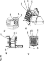
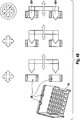
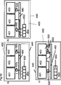
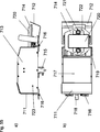
In einer bevorzugten Ausführungsform umfasst die Analysevorrichtung (400) zumindest ein Modul (401) zur Bearbeitung eines Analyten, wobei die Bearbeitung die Pipettierung einer Flüssigkeit umfasst. Das Bearbeitungsmodul (401) umfasst:

  • a) einen Prozesskopf (35) zum Einsetzen von Pipettenspitzen (3, 4), wobei der Prozesskopf (35) Positionierelemente (36) umfasst, die an der unteren Fläche (61) des Prozesskopfes (35) angeordnet sind,
  • b) das Spitzengestell (60, 70) enthaltend Pipettenspitzen (3, 4), wobei das Pipettenspitzen-Gestell (60, 70) Positionierelemente (31, 32, 33, 34) umfasst, die in der Lage sind, mechanisch mit den Positionierelementen (36) an dem Prozesskopf (35) zusammenzuwirken.
In a preferred embodiment, the analysis device ( 400 ) at least one module ( 401 ) for processing an analyte, wherein the processing comprises the pipetting of a liquid. The editing module ( 401 ) comprises:
  • a) a process head ( 35 ) for inserting pipette tips ( 3 . 4 ), the process head ( 35 ) Positioning elements ( 36 ) located on the lower surface ( 61 ) of the process head ( 35 ) are arranged
  • b) the top frame ( 60 . 70 ) containing pipette tips ( 3 . 4 ), wherein the pipette tip frame ( 60 . 70 ) Positioning elements ( 31 . 32 . 33 . 34 ) which are capable of being mechanically connected to the positioning elements ( 36 ) on the process head ( 35 ) to cooperate.

In einer bevorzugten Ausführungsform der im Vorangegangenen beschriebenen Analysevorrichtung (400) ist das Bearbeitungsmodul (401) ein Modul zur Isolation und Reinigung eins Analyten. Daher kann die Bezeichnung ”Bearbeitung” im vorliegenden Zusammenhang so verstanden werden, dass sie sich auf Isolierung und/oder Trennung und/oder Einfangen und/oder Reinigung des Analyten bezieht. Vorzugsweise umfasst die Vorrichtung (400) ein Modul zur Präparation der Probenaufarbeitung (402). Vorzugsweise umfasst die Vorrichtung (400) ein Modul zur Amplifikation des Analyten (403). In einem bevorzugten Ausführungsbeispiel umfasst die Vorrichtung zusätzlich ein Modul (404) zum Transferieren von Amplifikationsreagenzien von einem Aufbewahrungsbehälter zu einem Behälter, der einen gereinigten Analyten umfasst. Weitere bevorzugte Ausführungsformen der Vorrichtungen sind wie im Vorangegangenen und im Folgenden beschrieben.In a preferred embodiment of the above-described analysis device ( 400 ) is the processing module ( 401 ) a module for isolation and purification of one analyte. Therefore, the term "processing" in the present context may be understood to refer to isolation and / or separation and / or capture and / or purification of the analyte. Preferably, the device comprises 400 ) a module for preparing the sample preparation ( 402 ). Preferably, the device comprises 400 ) a module for amplifying the analyte ( 403 ). In a preferred embodiment, the device additionally comprises a module ( 404 ) for transferring amplification reagents from a storage container to a container comprising a purified analyte. Further preferred embodiments of the devices are as described above and below.

Ein zu verwendender automatisierter Analysator (400) zum Durchführen von Nukleinsäure-basierter Amplifikationsreaktion ist ebenfalls beschrieben. Der Analysator umfasst eine Vielzahl von Modulen (401, 402, 403). Ein Modul ist ein Bearbeitungsmodul, das im Analysator an einem ersten Ort angeordnet ist und so gestaltet und ausgebildet ist, eine Nukleinsäure von anderen Materialien in der Probe zu trennen. Das Bearbeitungsmodul umfasst eine Trenneinrichtung wie hier beschrieben. Der Analysator umfasst des Weiteren ein Amplifikationsmodul, das an einem zweiten Ort im Analysator vorgesehen und ausgebildet ist. Das Amplifikationsmodul umfasst einen temperaturkontrollierten Inkubator zur Inkubation des Inhalts von zumindest einem Behälter, vorzugsweise einer Multititerplatte, die die aufgetrennte Nukleinsäure und ein oder mehr Amplifikationsreagenzien zur Produktion eines Amplifikationsprodukts umfasst, das auf Target-Nukleinsäure in der Probe hinweist.An automated analyzer to use ( 400 ) for performing nucleic acid-based amplification reaction is also described. The analyzer includes a large number of modules ( 401 . 402 . 403 ). A module is a processing module located in the analyzer at a first location and configured and configured to separate a nucleic acid from other materials in the sample. The processing module includes a separator as described herein. The analyzer further comprises an amplification module provided and formed at a second location in the analyzer. The amplification module comprises a temperature-controlled incubator for incubating the contents of at least one container, preferably a multi-well plate, comprising the separated nucleic acid and one or more amplification reagents for producing an amplification product indicative of target nucleic acid in the sample.

Ein Analysesystem, das eine Haltestation und einen Satz von Multititerplatten umfasst, wie hier beschrieben, ist eine weitere bevorzugte Ausführungsform des Analysesystems, wie hier beschrieben. Vorzugsweise ist der Satz von Multititerplatten in der Haltestation fixiert. Vorzugsweise umfasst die Multititerplatte eine Basis mit einem Rand, der Aussparungen umfasst, wobei ein Positionier- und Fixierelement, vorzugsweise einen Schnappriegel (7a) und b)), an der Haltestation die Aussparung kontaktiert, wobei der Kontakt Druck auf die Basis der Multititerplatte ausübt und so die Multititerplatte in der Haltestation fixiert. Weitere bevorzugte Ausführungsformen des Analysesystems umfassen einzelne oder kombinierte Merkmale, wie hier beschrieben.An analysis system comprising a holding station and a set of multi-well plates as described herein is another preferred embodiment of the analysis system as described herein. Preferably, the set of multi-well plates is fixed in the holding station. Preferably, the multi-well plate comprises a base with a rim comprising recesses, wherein a positioning and fixing element, preferably a latch ( 7a) and b)), contacting the recess at the holding station, the contact exerting pressure on the base of the multi-well plate and thus fixing the multi-well plate in the holding station. Other preferred embodiments of the analysis system include single or combined features as described herein.

Weiterhin ist ein Analyseinstrument beschrieben, das umfasst:

  • – ein Bearbeitungsmodul zum Isolieren und Reinigen eines Analyten, das eine Haltestation (470) zum Halten eines Gestells enthaltend Pipettenspitzen umfasst, das Gestell umfassend zumindest eine Aussparung an einer Seitenwand des Gestells und zumindest eine Aussparung, die an einer gegenüberliegenden zweiten Seitenwand des Gestells angeordnet ist, wobei die Haltestation ein Fixierelement umfasst, vorzugsweise einen Schnappriegel, und wobei das Fixierelement, vorzugsweise ein Schnappriegel, mit der Aussparung so zusammenwirkt, dass eine Kraft auf die Basis der Aussparung ausgeübt wird; und
  • – ein Modul (403) zur Analyse des gereinigten Analyten durch Reaktion des Analyten mit Reagenzien, notwendig um ein detektierbares Signal zu erhalten.
Furthermore, an analytical instrument is described, which comprises:
  • A processing module for isolating and purifying an analyte containing a holding station ( 470 ) for holding a rack containing pipette tips, the rack comprising at least one recess on a side wall of the rack and at least one recess disposed on an opposite second side wall of the rack, the holding station comprising a fixing element, preferably a latch, and wherein the Fixing element, preferably a latch, with the recess cooperates such that a force is exerted on the base of the recess; and
  • - a module ( 403 ) to analyze the purified analyte by reacting the analyte with reagents necessary to obtain a detectable signal.

Das Analyseinstrument umfasst zusätzlich vorzugsweise ein Modul zur Handhabung von Flüssigkeit (404, 500). Weitere Ausführungsformen und bevorzugte Ausführungsformen des Analyseinstruments sind hier beschrieben, entweder einzeln oder als Kombination von Ausführungsformen. bevorzugte Ausführungsformen der Analysatoren sind in 38 und 51 gezeigt.The analytical instrument additionally preferably comprises a module for handling liquid ( 404 . 500 ). Further embodiments and preferred embodiments of the analytical instrument are described herein, either individually or as a combination of embodiments. preferred embodiments of the analyzers are in 38 and 51 shown.

Das Analyseinstrument, wie hier beschrieben, umfasst vorzugsweise zusätzlich eine Dichtstation (410). Die Dichtstation (410) ist vorzugsweise in dem Bearbeitungsmodul (401) lokalisiert.The analytical instrument, as described here, preferably additionally comprises a sealing station ( 410 ). The sealing station ( 410 ) is preferably in the processing module ( 401 ) isolated.

Die Bezeichnungen ”Modul” und ”Zelle” sind hier austauschbar verwendbar.The terms "module" and "cell" can be used interchangeably here.

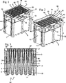
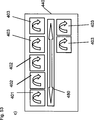
Spitzengestelltip rack

Ein Spitzengestell ist offenbart. Derartige Spitzengestelle umfassen Pipettenspitzen. Spitzengestelle werden im Allgemeinen in Analysesystemen zur Bereitstellung von Pipettenspitzen für zu Pipettierende Flüssigkeiten in dem System verwendet. Solche Spitzen sind Wegwerfartikel, aber können zumindest einmal wiederverwendet werden. Das Spitzengestell umfasst unabhängige Kammern, um Pipettenspitzen aufzunehmen.A lace rack is disclosed. Such tip racks include pipette tips. Tip racks are commonly used in analytical systems for providing pipette tips for liquids to be pipetted in the system. Such tips are disposable, but can be reused at least once. The top rack includes independent chambers to accommodate pipette tips.

Ein bevorzugtes Gestell zum Halten von Pipettenspitzen ist beschrieben. Das Gestell umfasst unabhängige Kammern zur Aufnahme von zumindest einem ersten Typ von Pipettenspitzen und einem zweiten Typ von Pipettenspitzen. In einer Ausführungsform umfasst das Gestell mehr als einen Teil. In einer anderen Ausführungsform ist das Gestell ein integrales einteiliges Gestell. Vorzugsweise ist das Volumen des ersten Typs von Pipettenspitzen zumindest 1 ml und das Volumen des zweiten Typs von Pipettenspitzen weniger als 1 ml. Besonders bevorzugt ist das Volumen des ersten Typs von Pipettenspitzen zwischen 1 ml und 1,5 ml und das Volumen des zweiten Typs von Pipettenspitzen zwischen 10 μl und 600 μl.A preferred rack for holding pipette tips is described. The rack includes independent chambers for receiving at least a first type of pipette tips and a second type of pipette tips. In one embodiment, the frame comprises more than one part. In another embodiment, the frame is an integral one-piece frame. Preferably, the volume of the first type of pipette tips is at least 1 ml and the volume of the second type of pipette tips is less than 1 ml. More preferably, the volume of the first type of pipette tips is between 1 ml and 1.5 ml and the volume of the second type of Pipette tips between 10 μl and 600 μl.

Vorzugsweise werden der erste Typ von Pipettenspitzen und der zweite Typ von Pipettenspitzen in dem Gestell in alternierenden Reihen aufbewahrt. In einer Ausführungsform umfasst das Gestell 48 Pipettenspitzen eines ersten Typs und 48 Pipettenspitzen eines zweiten Typs. Eine andere Anzahl von Spitzen ist aber ebenfalls umfasst. Das Gestell kann auch mehr Pipettenspitzen des einen Typs als Pipettenspitzen des anderen Typs umfassen.Preferably, the first type of pipette tips and the second type of pipette tips are stored in the rack in alternating rows. In one embodiment, the rack 48 includes pipette tips of a first type and 48 pipette tips of a second type. A different number of tips is also included. The rack may also include more pipette tips of one type than pipette tips of the other type.

In einer Ausführungsform sind die unabhängigen Kammern Behälter.In one embodiment, the independent chambers are containers.

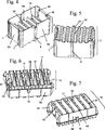
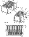
Ein dreiteiliges Gestell zum Halten von Pipettenspitzen ist beschrieben. Das Gestell umfasst Merkmale, die es besonders geeignet für automatisierte Systeme machen. Das Gestell umfasst drei Teile. Ein oberes Gestell umfasst eine Oberflächenplatte, wobei die Oberflächenplatte Durchgangsbohrungen mit einem Sitzbereich zum Einfügen der Pipettenspitzen in das Gestell umfasst. Das Gestell umfasst auch ein unteres Gestell. Das untere Gestell umfasst unabhängige Kammern zur Aufnahme von Pipettenspitzen eines ersten Typs. Der dritte Teil des Gestells ist ein Einsatzgestell. Das Einsatzgestell ist in dem unteren Gestell eingefügt. Das Einsatzgestell umfasst Kammern zur Aufnahme von Pipettenspitzen eines zweiten Typs. Das obere Gestell ist auf der Oberseite des unteren Gestells und des Einsatzgestells aufgesetzt.A three piece rack for holding pipette tips is described. The frame includes features that make it particularly suitable for automated systems. The frame consists of three parts. An upper frame comprises a surface plate, the surface plate comprising through-holes with a seating area for inserting the pipette tips into the frame. The frame also includes a lower frame. The lower frame includes independent chambers for receiving pipette tips of a first type. The third part of the frame is an insert frame. The insert frame is inserted in the lower frame. The deployment rack includes chambers for receiving pipette tips of a second type. The upper frame is placed on top of the lower frame and the insert frame.

Das Gestell ist somit geeignet, mehr als einen Typ von Pipettenspitzen aufzunehmen. Dies ist nützlich in Systemen, in denen verschiedene Volumina von Flüssigkeit mit Pipettenspitzen pipettiert werden.The rack is thus capable of accommodating more than one type of pipette tips. This is useful in systems where different volumes of liquid are pipetted with pipette tips.

Das hier beschriebene Gestell umfasst einen Kontaminationsschutz zum Schutz einzelner Spitzen vor Kontamination untereinander. Eine solche Kontamination kann durch Tropfen oder Aerosole entstehen. Ein solcher Schutz ist besonders wichtig, wenn die Pipettenspitzen nach der ersten Benutzung in dem Gestell platziert werden, bevor sie wieder benutzt werden. Daher umfasst das Gestell vorzugsweise Reihen von offenen Kammern, um einen zweiten Typ von Pipettenspitzen zu halten. Besonders bevorzugt haben diese offenen Kammern einen Boden. Dieser Boden separiert die Kammer, die den zweiten Typ von Pipettenspitzen hält, von den Kammern, die den ersten Typ von Pipettenspitzen halten. Dies reduziert das Risiko der Kontaminationen zwischen dem ersten und dem zweiten Typ von Spitzen.The frame described here includes a contamination protection to protect individual tips from contamination with each other. Such contamination can be caused by drops or aerosols. Such protection is particularly important if the pipette tips are placed in the rack after initial use before being reused. Therefore, the rack preferably includes rows of open chambers to hold a second type of pipette tips. Most preferably, these open chambers have a bottom. This bottom separates the chamber holding the second type of pipette tips from the chambers holding the first type of pipette tips. This reduces the risk of contamination between the first and second types of tips.

In einer bevorzugten Ausführungsform wechseln sich die Reihen der offenen Kammern zum Halten der Pipettenspitzen des zweiten Typs mit den Reihen der unabhängigen Kammern zur Aufnahme der Pipettenspitzen des ersten Typs ab. Vorzugsweise ist die innere Fläche der unabhängigen Kammern in dem unteren Teil des Gestells zur Aufnahme der Pipettenspitzen eines ersten Typs größer als die innere Fläche der Durchgangsbohrung zum Einsetzen von Pipettenspitzen.In a preferred embodiment, the rows of open chambers for holding the pipette tips of the second type alternate with the rows of independent chambers for receiving the pipette tips of the first type. Preferably, the inner surface of the independent chambers in the lower part of the rack for receiving the pipette tips of a first type is larger than the inner surface of the through hole for inserting pipette tips.

In einer bevorzugten Ausführungsform verläuft eine Wand, die an der Innenseite der Seitenwand der unabhängigen Kammern des unteren Gestells zum Halten von Pipettenspitzen eines ersten Typs vorgesehen sind, vom Boden des unteren Gestells bis unter das obere Ende der Seitenwand der unabhängigen Kammern des unteren Gestells. Bevorzugte Ausführungsformen wie im Vorangegangenen und im Folgenden beschrieben, beziehen sich auf ein Gestell, das Pipettenspitzen eines ersten Typs umfasst, besonders bevorzugt zusätzlich Pipettenspitzen eines zweiten Typs umfassend.In a preferred embodiment, a wall extending on the inside of the Side wall of the independent chambers of the lower frame for holding pipette tips of a first type are provided, from the bottom of the lower frame to below the upper end of the side wall of the independent chambers of the lower frame. Preferred embodiments as described above and in the following relate to a frame comprising pipette tips of a first type, particularly preferably additionally comprising pipette tips of a second type.

Weitere bevorzugte Ausführungsformen eines jeden Spitzengestells, wie hier beschrieben, umfassen Merkmale, die im Vorangegangenen und im Folgenden beschrieben sind, ohne Begrenzung auf eine spezielle Ausführungsform durch Kombination mit jeder beliebigen anderen Ausführungsform, wie hier beschrieben.Further preferred embodiments of each tip rack as described herein include features described above and below, without limitation to a particular embodiment, by combination with any other embodiment as described herein.

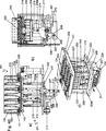
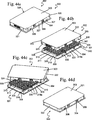
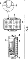
Eine erste Ausführungsform eines exemplarischen Gestells (60) (1 und 2) umfasst eine Vielzahl von Teilen. Ein oberes Gestell (1), ein unteres Gestell (2) und ein Einsatzgestell (14) sind zu einem Gestell montiert, um Pipettenspitzen (4) zu halten und wieder zu verwerten. In einer bevorzugten Ausführungsform werden Pipettenspitzen eines ersten Typs (4) und eines zweiten Typs (3) in dem Gestell (60) gehalten. In einer besonders bevorzugten Ausführungsform werden die Spitzen (4) zum Beproben, Isolieren und Reinigen eines Analyten und Spitzen (3) zum Transferieren des eloierten Analyts in einem Gestell gemäß der vorliegenden Erfindung gehalten. Ganz besonders bevorzugt umfasst das Gestell (60) verlängerte Spitzen mit einem großen Volumen (4) und kurze Spitzen mit einem kleinen Volumen (3). Bevorzugte Ausführungsformen der drei Teile des Gestells sind im Folgenden beschrieben.A first embodiment of an exemplary frame ( 60 ) ( 1 and 2 ) comprises a plurality of parts. An upper frame ( 1 ), a lower frame ( 2 ) and an insert frame ( 14 ) are mounted to a rack to hold pipette tips ( 4 ) and to recycle. In a preferred embodiment, pipette tips of a first type ( 4 ) and a second type ( 3 ) in the frame ( 60 ) held. In a particularly preferred embodiment, the tips ( 4 ) for sampling, isolating and purifying an analyte and tips ( 3 ) for transferring the eluted analyte in a rack according to the present invention. Most preferably, the frame ( 60 ) extended tips with a large volume ( 4 ) and short tips with a small volume ( 3 ). Preferred embodiments of the three parts of the frame are described below.

Oberes Gestell (1)Upper frame ( 1 )

Das obere Gestell (1) umfasst einen Rahmen (50) und eine Oberflächenplatte (51), die im Rahmen (50) platziert ist (9, 10). Die Oberflächenplatte (51) umfasst Durchgangsbohrungen (23, 25) (4). Auf der Unterseite (62) der Oberflächenplatte (51) sind Separationswände (16) und Separationslamellen (18) zwischen den Durchgangsbohrungen (23, 25) vorhanden. Diese ermöglichen zusätzlichen Schutz vor Kontamination zwischen Spitzen (3, 4) und verleihen dem oberen Gestell (1) zusätzliche Stabilität. Bestimmte Separationswände (16) umfassen auch eine Aussparung (13). Die Aussparung (13) erlaubt den Separationswänden (15) des Einsatzgestells (14) mit den Separationswänden (16) des oberen Gestells (1) durch einen Überdeckung zusammenzuwirken, um gegen horizontal fliegende Tropfen im Falle von platzen Blasen während der Spitzenhandhabung der Spitzen (4) abzudichten. Vorzugsweise wechseln sich Separationslamellen (18) mit Aussparungen (13) mit Separationslamellen (18) ohne Aussparungen ab.The upper frame ( 1 ) includes a frame ( 50 ) and a surface plate ( 51 ), which are under 50 ) is placed ( 9 . 10 ). The surface plate ( 51 ) comprises through holes ( 23 . 25 ) ( 4 ). On the bottom ( 62 ) of the surface plate ( 51 ) are separation walls ( 16 ) and separation lamellae ( 18 ) between the through holes ( 23 . 25 ) available. These allow additional protection against contamination between peaks ( 3 . 4 ) and give the upper frame ( 1 ) additional stability. Certain separation walls ( 16 ) also include a recess ( 13 ). The recess ( 13 ) allows the separation walls ( 15 ) of the insert frame ( 14 ) with the separation walls ( 16 ) of the upper frame ( 1 ) to cooperate by overlapping against horizontal flying drops in the event of bursting blisters during peak tip handling ( 4 ) seal. Preferably, separation lamellae alternate ( 18 ) with recesses ( 13 ) with separation lamellae ( 18 ) without recesses.

Unteres Gestell (2)Lower frame ( 2 )

Unteres Gestell (2) umfasst zwei lange Seitenwände (52), die gegenüber voneinander platziert sind, und zwei kurze Seitenwände (53), die gegenüber voneinander platziert sind (5 und 6). Jede kurze Seitenwand (53) kontaktiert beide lange Seitenwände (52), um einen Rahmen zu bilden. Der Innenraum, definiert durch die Seitenwände (52) und (53), umfasst Kammern (19), die durch innere Aufteilungswände (54) mit Stegen (9) und senkrecht zu den Wänden (54) zweiten Wanden (55) ausgebildet werden. Die Kammern (19) umfassen Böden (21), die vorzugsweise abgerundet sind.Lower frame ( 2 ) comprises two long side walls ( 52 ), which are placed opposite each other, and two short side walls ( 53 ) placed opposite each other ( 5 and 6 ). Every short sidewall ( 53 ) contacts both long side walls ( 52 ) to form a frame. The interior, defined by the side walls ( 52 ) and ( 53 ), includes chambers ( 19 ), which are separated by inner dividing walls ( 54 ) with bars ( 9 ) and perpendicular to the walls ( 54 ) second walls ( 55 ) be formed. The chambers ( 19 ) include soils ( 21 ), which are preferably rounded.

Unteres Gestell (2) umfasst an der Außenseite der Wände (52) und (53) Stapelführungselemente (6) und (7), die vorzugsweise auch als Teilerkennung dienen.Lower frame ( 2 ) on the outside of the walls ( 52 ) and ( 53 ) Stack guide elements ( 6 ) and ( 7 ), which preferably also serve as partial recognition.

Einsatzgestell (14) umfasst drei lange Frontwände (56) und zwei kurze Seitenwände (57). Kammern (24) sind durch die Separationswände (15) gebildet, die parallel zu den kurzen Seitenwänden (57) angeordnet sind (7, 8). Diese Kammern (24) haben Böden (58) und können Spitzen eines zweiten Typs (3) aufnehmen. Zwischen jeder Kammer (24) ist ein Durchgang (17) für einen ersten Typ von Spitzen (4) vorgesehen, der in die Kammern (19) des unteren Gestells (2) hineinreicht. Die Kammern (24) umfassen vorzugsweise Stabilisierungsrippen (41). Das Einsatzgestell (14) umfasst vorzugsweise zusätzliche Stabilisierungsrippen (42, 43).Insert frame ( 14 ) comprises three long front walls ( 56 ) and two short side walls ( 57 ). Chambers ( 24 ) are separated by the separation walls ( 15 ) formed parallel to the short side walls ( 57 ) are arranged ( 7 . 8th ). These chambers ( 24 ) have soils ( 58 ) and can be tips of a second type ( 3 ) take up. Between each chamber ( 24 ) is a passage ( 17 ) for a first type of tips ( 4 ), which enters the chambers ( 19 ) of the lower frame ( 2 ). The chambers ( 24 ) preferably comprise stabilizing ribs ( 41 ). The insert frame ( 14 ) preferably comprises additional stabilizing ribs ( 42 . 43 ).

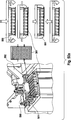
Kombiniertes Pipettenspitzen GestellCombined pipette tips frame

Die Konstruktion des Gestells (60) aus vielen Teilen hat unterschiedliche Vorteile. Ein Vorteil ist es, dass die Spitzen (4) mit länglicher Form für die Pippetierung großer Volumina in unabhängigen, dicht gepackten Kammern (19) aufbewahrt werden können. Die Spitzen (4) benötigen somit nur einen begrenzten Platz in einer horizontalen Ebene zum Aufbewahren, wobei diese trotzdem in der Lage sind, große Volumina von Flüssigkeit zu halten.The construction of the frame ( 60 ) from many parts has different advantages. An advantage is that the tips ( 4 ) of elongated shape for large volume pipetting in independent densely packed chambers ( 19 ) can be stored. The tips ( 4 ) thus require only a limited space in a horizontal plane for storage, while still being able to hold large volumes of liquid.

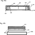
Ansichten einer vorteilhaften Ausführungsform sind in 1 bis 24 dargestellt.Views of an advantageous embodiment are in 1 to 24 shown.

Als weiterer Vorteil sei zu erwähnen, dass die innere, horizontale Querschnittsfläche der Kammern (19) für Spitzen (4) größer ist, als der Querschnitt der Durchgangsbohrungen der Sitzfläche (22) (3). Dies beugt Kapillarkräften vor, die zum Transport von Flüssigkeit zwischen den Kammern (19) führen können.As a further advantage, it should be mentioned that the inner, horizontal cross-sectional area of the chambers ( 19 ) for tips ( 4 ) is greater than the cross section of the through holes of the seat ( 22 ) ( 3 ). This prevents capillary forces that are required to transport liquid between the chambers ( 19 ) being able to lead.

Ein weiterer Vorteil dieser Konstruktion des Pipettenspitzen-Gestells (60) ist, dass die Innenwände (54) der Kammern (19) nicht kontinuierlich vom Boden (21) der Kammer (19) zu der Sitzfläche (22) reichen (3). Somit kann dem Transport von Flüssigkeit vom Boden (21) der Kammer (19) zu der Sitzfläche (22) und damit Kontamination vorgebeugt werden. Dies ermöglicht die Wiederverwertung der Pipettenspitzen (4). Zusätzlich umfassen die Kammern (19) eine Wand (5), die an der Innenfläche (65) vorgesehen ist (24). Die Wand (5) bedeckt vorzugsweise nur einen Teil der Höhe der Kammer (19). Besonders bevorzugt erstreckt sich die Wand (5) von oberhalb des Bodens (21) der Kammer (19) zu unterhalb dem Steg (9) der Innenfläche (65) der Wände (54) des unteren Gestells (2). Die Wand (5) beugt des Weiteren Kapillareffekten in Kammer (19) vor. Another advantage of this construction of the pipette tip frame ( 60 ) is that the inner walls ( 54 ) of the chambers ( 19 ) not continuously from the ground ( 21 ) the chamber ( 19 ) to the seat ( 22 ) pass ( 3 ). Thus, the transport of liquid from the ground ( 21 ) the chamber ( 19 ) to the seat ( 22 ) and thus prevent contamination. This allows the recycling of the pipette tips ( 4 ). In addition, the chambers ( 19 ) a wall ( 5 ) on the inner surface ( 65 ) is provided ( 24 ). The wall ( 5 ) preferably covers only part of the height of the chamber ( 19 ). Particularly preferably, the wall extends ( 5 ) from above the ground ( 21 ) the chamber ( 19 ) to below the bridge ( 9 ) of the inner surface ( 65 ) of the walls ( 54 ) of the lower frame ( 2 ). The wall ( 5 ) also prevents capillary effects in chamber ( 19 ) in front.

Ein weiterer Vorteil der Konstruktion des Spitzen-Gestells (60) ist, dass zwei unterschiedliche Typen von Spitzen in diesem aufbewahrt werden könnten (3). In der vorliegenden bevorzugten Ausführungsform wird ein zweiter Typ von Spitzen (3) in dem Spitzengestell (60) aufbewahrt. Der zweite Typ von Spitzen ist kürzer als der erste Typ von Spitzen und wird zur Pipettierung kleinerer Mengen von Flüssigkeit als bei der Pipettierung mit dem ersten Typ von Pipettenspitzen eingesetzt. In vorliegendem, bevorzugtem Beispiel wird der zweite Typ von Spitzen in den Kammern (24) innerhalb des Einsatzgestells (14) aufbewahrt, welche in einer höheren Ebene als die Kammern (19) platziert sind und hermetisch von den Kammern (19) separiert sind, aber in einer Reihe der Kammern (24) offen sind. Ein Vorteil dieser Konstruktion ist, dass sie platzsparend ist. Zusätzlich, dass die Kammern (24) im Einsatzgestell platziert sind, steht mehr Raum zur Verfügung, um Kontamination vorzubeugen, z. B. durch Kapillarkräfte zwischen den Kammern (19) des ersten Typs von Spitzen (4). In einer bevorzugten Ausführungsform wird nur der erste Typ von Spitzen (4) wieder verwertet, wobei der zweite Typ von Spitzen (3) nur einmal verwendet wird.Another advantage of the construction of the top frame ( 60 ) is that two different types of tips could be kept in it ( 3 ). In the present preferred embodiment, a second type of tip ( 3 ) in the top rack ( 60 ). The second type of tip is shorter than the first type of tip and is used for pipetting smaller quantities of liquid than when pipetting with the first type of pipette tips. In the present preferred example, the second type of peak in the chambers ( 24 ) within the deployment frame ( 14 ), which are at a higher level than the chambers ( 19 ) and hermetically from the chambers ( 19 ) are separated, but in a row of the chambers ( 24 ) are open. An advantage of this construction is that it saves space. In addition, that the chambers ( 24 ) are placed in the deployment rack, more space is available to prevent contamination, eg. B. by capillary forces between the chambers ( 19 ) of the first type of tips ( 4 ). In a preferred embodiment, only the first type of peaks ( 4 ), the second type of peak ( 3 ) is used only once.

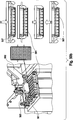
Einsatzgestell umfasst des Weiteren Stege (8) am Boden der Kammern (24) (3). Diese Stege (8) beugen Spritzern von Flüssigkeit vor, die durch das Formen von Blasen von Flüssigkeit an den Spitzenenden der Pipettenspitze (4) und Zerplatzen auf der Höhe der Stege (8) verursacht werden, vor dem Durchgang in die benachbarten Kammern (19). Das untere Gestell (2) umfasst am oberen Ende der Wände (54) zwischen Kammern (19) einen Steg (9). Der Steg (9) hat dieselbe Funktion wie der Steg (8). Steg (8) und (9) stehen nicht in Verbindung zueinander (23). Dies beugt Kapillareffekten vor.Insert frame further includes webs ( 8th ) at the bottom of the chambers ( 24 ) ( 3 ). These bridges ( 8th ) prevent splashes of liquid caused by the formation of bubbles of liquid at the tip ends of the pipette tip ( 4 ) and bursting at the height of the webs ( 8th ), before passing into the adjacent chambers ( 19 ). The lower frame ( 2 ) at the top of the walls ( 54 ) between chambers ( 19 ) a footbridge ( 9 ). The footbridge ( 9 ) has the same function as the bridge ( 8th ). Footbridge ( 8th ) and ( 9 ) are not related to each other ( 23 ). This prevents capillary effects.

Wenn die Spitzen (3, 4) im Gestell (60) aufbewahrt werden, sitzen diese auf der Sitzfläche (22, 26) einer Durchgangsbohrung (25, 23) (13, 14). Die Durchgangsbohrungen (25, 23) sind an einer Sitzfläche (22, 26) vorhanden. Vorzugsweise ist die Sitzfläche (22) der Durchgangsbohrungen (25) erhöht im Vergleich zu der Sitzfläche (26) der Durchgangsbohrungen (23) des ersten Typs von Spitzen (4). Das hat den Vorteil, dass wenn der erste Typ von Spitzen (4) entweder im Gestell ersetzt oder wieder aufgenommen wird für die Wiederverwendung, im Falle von Flüssigkeit von dem ersten Typ von Spitzen (4) die Sitzfläche (22) der Durchgangsbohrungen (25) kontaktiert, die Flüssigkeit nicht von der unteren Sitzfläche (22) zu der höheren Sitzfläche (26) aufsteigen kann und so Kontamination des zweiten Typs von Spitzen (3) vorbeugen kann.When the tips ( 3 . 4 ) in the frame ( 60 ) are stored on the seat ( 22 . 26 ) of a through hole ( 25 . 23 ) ( 13 . 14 ). The through holes ( 25 . 23 ) are on a seat ( 22 . 26 ) available. Preferably, the seat surface ( 22 ) of the through holes ( 25 ) increased compared to the seat ( 26 ) of the through holes ( 23 ) of the first type of tips ( 4 ). This has the advantage that if the first type of spikes ( 4 ) is either replaced in the rack or taken up again for reuse, in the case of liquid of the first type of spikes ( 4 ) the seat ( 22 ) of the through holes ( 25 ), does not contact the liquid from the lower seating surface ( 22 ) to the higher seating surface ( 26 ) and so contamination of the second type of tips ( 3 ) can prevent.

Vorzugsweise trennen zusätzliche Kapillarkanäle (40) benachbarte Durchgangsbohrungen (23) auf Höhe der unteren Sitzfläche (22) und leiten jegliche Flüssigkeit im Kontakt mit der unteren Sitzfläche (22) oder den Durchgangsbohrungen (23) ab (4, 9, 13, 14). Dies vermeidet Kontamination der benachbarten Durchgangsbohrung (23, 25). Ein zusätzlicher Vorteil der Kapillarkanäle (40) ist, dass die Flüssigkeit auf einer großen Fläche verteilt ist und schneller evaporieren kann.Preferably separate additional capillary channels ( 40 ) adjacent through holes ( 23 ) at the level of the lower seating surface ( 22 ) and conduct any liquid in contact with the lower seat surface ( 22 ) or the through holes ( 23 ) ( 4 . 9 . 13 . 14 ). This avoids contamination of the adjacent through-hole ( 23 . 25 ). An additional advantage of the capillary channels ( 40 ) is that the liquid is distributed over a large area and can evaporate faster.

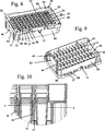
In einer bevorzugten Ausführungsform umfassen die Pipettenspitzen eine Aufnahmerippe (27, 28), die die Sitzflächen (22, 26) der Durchgangsbohrungen (23, 25) kontaktieren, wenn die Pipettenspitze (3, 4) im Gestell (60) sitzt (15, 16). In besonders vorteilhafter Weise weisen die Spitzen des zweiten Typs (3) kürzere Aufnahmerippen (27) als die Spitzen des ersten Typs (4) auf. Der Unterschied in der Höhe zwischen Aufnahmerippe (27) und (28) entspricht dem Unterschied in der Höhe des Randes der Durchgangsbohrungen (23) und (25). Dies hat den Vorteil, dass alle Pipettenspitzen (3, 4) sich zur Verbindung mit dem Prozesskopf (35) auf derselben Höhe befinden, aber die Pipettenspitzen des zweiten Typs (3) zur gleichen Zeit auf einer höheren Ebene auf dem Gestell sitzen können, um Kontamination durch Flüssigkeit von dem ersten Typ von Spitzen (4) zu vermeiden. Des Weiteren ermöglicht dies eine visuelle Kontrolle für die korrekte Anordnung ersten und zweiten Typs von Pipettenspitzen (3, 4) im Gestell (60), weil die Oberseite der Spitzen (3, 4), die in der falsche Position sitzen, auf einer niedrigeren oder höheren Ebene sitzen würden als korrekt platzierte Spitzen (3, 4).In a preferred embodiment, the pipette tips comprise a receiving lip ( 27 . 28 ), the seats ( 22 . 26 ) of the through holes ( 23 . 25 ) when the pipette tip ( 3 . 4 ) in the frame ( 60 ) sits ( 15 . 16 ). In a particularly advantageous manner, the tips of the second type ( 3 ) shorter recording ribs ( 27 ) as the tips of the first type ( 4 ) on. The difference in height between picking rib ( 27 ) and ( 28 ) corresponds to the difference in the height of the edge of the through holes ( 23 ) and ( 25 ). This has the advantage that all pipette tips ( 3 . 4 ) for connection to the process head ( 35 ) are at the same height, but the pipette tips of the second type ( 3 ) can sit on the rack at a higher level at the same time to prevent liquid contamination from the first type of spike ( 4 ) to avoid. Furthermore, this allows a visual check for the correct arrangement of first and second type pipette tips ( 3 . 4 ) in the frame ( 60 ), because the top of the tips ( 3 . 4 ) sitting in the wrong position would sit at a lower or higher level than correctly placed points ( 3 . 4 ).

Die Aufnahmerippen (27, 28) an der Spitz (3, 4) umfassen keine kontinuierlich umlaufende Sitzbasis (59) zum Kontaktieren des Randes der Durchgangsbohrung (23, 25). Die Sitzbasis (59) steht nur punktuell im Kontakt mit den Sitzflächen (22, 26). Ein Vorteil ist, dass weniger Material für die Spitze (3, 4) verwendet wird und dass die Spitze (3, 4) mit höherer Genauigkeit und weniger Belastung produziert werden kann. Die reduzierte Kontaktfläche zwischen der Spitze (3, 4) und der Sitzfläche (22, 26) hat den zusätzlichen Vorteil, dass elektrostatische Ladung der Spitzen (3, 4) reduziert ist.The recording ribs ( 27 . 28 ) at the Spitz ( 3 . 4 ) do not comprise a continuously circulating seat base ( 59 ) for contacting the edge of the through-bore ( 23 . 25 ). The seat base ( 59 ) is only occasionally in contact with the seats ( 22 . 26 ). An advantage is that less material for the tip ( 3 . 4 ) and that the tip ( 3 . 4 ) can be produced with higher accuracy and less stress. The reduced contact area between the tip ( 3 . 4 ) and the seat ( 22 . 26 ) has the additional advantage that electrostatic charge of the tips ( 3 . 4 ) is reduced.

Spitze (3, 4) ist im Bereich des Schafts (29) mit einer Oberflächenrauhigkeit von 0,8 bis 1,6 im mattiert und im Bereich des Spitzenendes (30) poliert. Die mattierte Oberfläche des Schafts (29) erlaubt es, dass Flüssigkeitstropfen flach an der Oberfläche anliegen und schneller evaporieren. Wenn somit Spitze (4) in die Durchgangsbohrung (23, 25) eingebracht wird, kann keine oder weniger Flüssigkeit abgestrichen werden, wenn die Spitze (4) die Sitzfläche (22, 26) kontaktiert und somit das Risiko einer Kontamination reduziert ist. Das polierte Spitzenende (30) verursacht, dass Tropfen von Flüssigkeit an den Spitzenenden (30) in einer perlenartigen Weise verbleiben und von dem Spitzenende (30) abgestrichen werden, wenn die Spitze (4) aus der Flüssigkeit auftaucht. Das Spitzenende (30) verbleibt somit ohne anhaftende Flüssigkeit.Top ( 3 . 4 ) is in the area of the shaft ( 29 ) with a surface roughness of 0.8 to 1.6 in matt and in the area of the tip end ( 30 ) polished. The frosted surface of the shaft ( 29 ) allows liquid drops to lie flat against the surface and evaporate faster. So if tip ( 4 ) in the through hole ( 23 . 25 ), no or less liquid can be scraped off when the tip ( 4 ) the seat ( 22 . 26 ) and thus the risk of contamination is reduced. The polished top end ( 30 ) causes drops of liquid at the tip ends ( 30 ) remain in a bead-like manner and from the tip end ( 30 ) are stripped off when the tip ( 4 ) emerges from the liquid. The top end ( 30 ) thus remains without adhering liquid.

Das obere Gestells (1) umfasst vorzugsweise einen ersten Typ von Positionierelementen (10) (21, 22) und einen zweiten Typ von Positionierelementen (31, 32, 33, 34) (17, 18). Der erste Typ der Positionierelemente (10) ermöglicht eine näherungsweise Positionierung des Gestells (60) relativ zu einem Prozesskopf (35), während der zweite Typ von Positionierelementen (31, 32, 33, 34) eine präzise Positionierung des Gestells (60) relativ zu dem Prozesskopf (35) ermöglicht. Die ungefähre Positionierung durch den ersten Typ der Positionierelemente (10) stellt sicher, dass der zweite Typ der Positionierelemente (31, 33) oder (32, 34) mit den Gegenpositionierelementen (36) an dem Prozesskopf (35) ausgerichtet sind. Der Vorteil der zwei Typen der Positionierelemente ist, dass die Positionierung des Gestells (60) und des Prozesskopfes (35) zur Aufnahme der Spitzen schnell und präzise ist.The upper frame ( 1 ) preferably comprises a first type of positioning elements ( 10 ) ( 21 . 22 ) and a second type of positioning elements ( 31 . 32 . 33 . 34 ) ( 17 . 18 ). The first type of positioning elements ( 10 ) allows an approximate positioning of the frame ( 60 ) relative to a process head ( 35 ), while the second type of positioning elements ( 31 . 32 . 33 . 34 ) a precise positioning of the frame ( 60 ) relative to the process head ( 35 ). The approximate positioning by the first type of positioning elements ( 10 ) ensures that the second type of positioning elements ( 31 . 33 ) or ( 32 . 34 ) with the Gegenpositionierelementen ( 36 ) on the process head ( 35 ) are aligned. The advantage of the two types of positioning elements is that the positioning of the frame ( 60 ) and the process header ( 35 ) is quick and accurate to pick up the tips.

Der zweite Typ der Positionierelemente (31, 33) oder (32, 34) ist vorzugsweise an der Oberseite vorgesehen (auch bezeichnet als Oberflächenplatte) (51) des Gestells (60) (17 bis 20). Die Gegenpositionierelemente (36) sind vorzugsweise an der Unterseite (61) des Prozesskopfes (35) vorgesehen.The second type of positioning elements ( 31 . 33 ) or ( 32 . 34 ) is preferably provided at the top (also referred to as surface plate) ( 51 ) of the frame ( 60 ) ( 17 to 20 ). The counter positioning elements ( 36 ) are preferably at the bottom ( 61 ) of the process head ( 35 ) intended.

In einer bevorzugten Ausführungsform greifen die Positionierelemente (31, 33) mit dem Gegenpositionierelement (36) am Prozesskopf (35) ineinander, um den ersten Typ von Pipettenspitzen (4) mit der Schnittstelle des Prozesskopfes (35) auszurichten (17, 18). Alternativ greifen Positionierelemente (32, 34) mit Gegenelementen (36) am Prozesskopf (35) ineinander, um den zweiten Typ von Pipettenspitzen (3) mit der Schnittstelle (67) des Prozesskopfes (35) auszurichten (19, 20).In a preferred embodiment, the positioning elements ( 31 . 33 ) with the Gegenpositionierelement ( 36 ) on the process head ( 35 ) into each other to form the first type of pipette tips ( 4 ) with the interface of the process head ( 35 ) ( 17 . 18 ). Alternatively, positioning elements ( 32 . 34 ) with counter elements ( 36 ) on the process head ( 35 ) into each other to form the second type of pipette tips ( 3 ) with the interface ( 67 ) of the process head ( 35 ) ( 19 . 20 ).

In einer bevorzugten Ausführungsform sind die Positionierelemente als Öffnung (31, 32, 33, 34) an der Oberseite (51) des Gestells (60), vorzugsweise in gegenüberliegenden Ecken der Oberseite (51) des Gestells, vorhanden (1). Die Gegenpositionierelemente sind in dieser bevorzugten Ausführungsform an der Unterseite (61) des Prozesskopfes (35) als Stäbe (36) ausgebildet, die in den korrespondierenden Ecken des Prozesskopfes (35) vorhanden sind. Öffnungen (31, 32, 33, 34) und Stäbe (36) sind so konstruiert, dass die Stäbe (36) mit den Öffnungen (31, 32) oder (33, 34) zur präzisen Ausrichtung des Gestells (60) und des Prozesskopfes (35) ineinandergreifen können. Damit kann die Spitze (3, 4) und die Schnittstelle (67) am Prozesskopf (35) zur Aufnahme der Spitzen (3, 4) präzise ausgerichtet werden und die Schnittstelle des Prozesskopfes (35) kann mit der Spitze (3, 4) ineinander eingreifen. In einer bevorzugteren Ausführungsform haben zwei der Öffnungen (31, 32) einen runden Querschnitt zur präzisen Positionierung in einer horizontalen Ebene. Öffnungen (33, 34) haben eine längliche Form zur Kompensation von Herstellungstoleranzen. Dies ist von Vorteil, weil das Gestell (60) präzise ohne ein Verkanten mit dem Prozesskopf (35) positioniert werden kann. Die Standfläche des Gestells umfasst vorzugsweise eine Länge und eine Breite der Basis, die im Wesentlichen zu der Basis des ANSI SBS Stellflächenformats korrespondiert. Besonders bevorzugt ist die Länge 127,76 mm +/– 0,25 mm und die Breite 85,48 mm +/– 0,25 mm. Das Gestell (60) umfasst Formschlusselemente (38) zum Zusammenwirken mit einem Bedienelement (500). Das Gestell (60) kann mit hoher Geschwindigkeit schnell und sicher gegriffen, transportiert und positioniert werden, während die korrekte Orientierung und Position erhalten bleibt.In a preferred embodiment, the positioning elements as an opening ( 31 . 32 . 33 . 34 ) at the top ( 51 ) of the frame ( 60 ), preferably in opposite corners of the top ( 51 ) of the frame, present ( 1 ). The Gegenpositionierelemente are in this preferred embodiment at the bottom ( 61 ) of the process head ( 35 ) as rods ( 36 ) formed in the corresponding corners of the process head ( 35 ) available. Openings ( 31 . 32 . 33 . 34 ) and bars ( 36 ) are constructed so that the rods ( 36 ) with the openings ( 31 . 32 ) or ( 33 . 34 ) for precise alignment of the frame ( 60 ) and the process header ( 35 ) can interlock. This allows the tip ( 3 . 4 ) and the interface ( 67 ) on the process head ( 35 ) for receiving the tips ( 3 . 4 ) and the interface of the process head ( 35 ) can with the top ( 3 . 4 ) interlock. In a more preferred embodiment, two of the openings ( 31 . 32 ) a round cross section for precise positioning in a horizontal plane. Openings ( 33 . 34 ) have an elongated shape to compensate for manufacturing tolerances. This is an advantage because the frame ( 60 ) precisely without jamming with the process head ( 35 ) can be positioned. The footprint of the frame preferably includes a length and a width of the base that substantially corresponds to the base of the ANSI SBS footprint format. More preferably, the length is 127.76mm +/- 0.25mm and the width is 85.48mm +/- 0.25mm. The frame ( 60 ) comprises positive-locking elements ( 38 ) for interaction with a control element ( 500 ). The frame ( 60 ) can be quickly and safely gripped, transported and positioned at high speed while maintaining the correct orientation and position.

Die Bezeichnung „im Wesentlichen korrespondierend zu ANSI SBS Stellflächenformat” bedeutet, dass die Basis eines jeden Verbrauchsmaterials heraus geschnittene Abschnitte haben kann, z. B. geschnittene Ecken. Somit kann die Flächengeometrie der unterschiedlichen Typen von Verbrauchsmaterialien mit ANSI SBS Stellflächenformat unterschiedlich sein. Aber die Basis eines jeden Verbrauchsmaterials passt in die Station, die einem korrespondierenden Aufnahmeteil in ANSI SBS Stelleflächenformat hat.The term "substantially corresponding to ANSI SBS footprint format" means that the base of each consumable may have cut sections, e.g. B. cut corners. Thus, the surface geometry of the different types of consumables may vary with ANSI SBS footprint format. But the base of each consumable fits in the station, which has a corresponding pickup part in ANSI SBS patch area format.

Das Gestell (60) umfasst ein oder mehrere Teilerkennungen (39), wobei die Teilerkennungen (39) eine integrale Einheit mit den Verbrauchsmaterialien bilden. Das Gestell (60) umfasst ferner Stapelführungselemente (6, 7). Die Teilerkennungen (39) und Stapelführungselemente (6, 7) umfassen Rippen und/oder Aussparung an den Seitenwänden der Verbrauchsmaterialien, wobei das Muster von Rippen und/oder Aussparungen einzigartig für jeden spezifischen Typ von Verbrauchsmaterial ist, vorzugsweise das Gestell (60). Die Stapelführungselemente (6, 7) und die Teilerkennungen (39) stellen sicher, dass der Anwender das Gestell (60) nur in die richtige Stapelposition des Analyseinstruments (46) laden kann.The frame ( 60 ) comprises one or more part identifiers ( 39 ), where the part identifications ( 39 ) form an integral unit with the consumables. The frame ( 60 ) further comprises stack guide elements ( 6 . 7 ). The part recognitions ( 39 ) and stack guide elements ( 6 . 7 ) comprise ribs and / or recesses on the side walls of the consumables, the pattern of ribs and / or recesses being unique to each specific type of consumable, preferably the frame ( 60 ). The stack guide elements ( 6 . 7 ) and the part identifications ( 39 ) make sure that the user the frame ( 60 ) only in the correct stacking position of the analytical instrument ( 46 ) can load.

Das Gestell (60) umfasst auch Aussparungen (37) in der Seitenwand des unteren Gestells (1). Die Aussparungen (37) umfassen eine Bodenwand (48) und Seitenwände (49). Das Gestell (60) ist in einer Öffnung in einem Analyseinstrument (46) positioniert. Wenn das Gestell (60) positioniert ist, kontaktiert die Bodenwand (48) der Aussparung (37) die Fläche des Prozessdecks (47) des Analyseinstruments (46). Die Aussparungen (37) wirken mit Gegenelementen an dem Analyseinstrument (46) zusammen, um das Gestell in dem Instrument nieder zu halten. Dies ermöglicht zusätzliche Stabilisierung des Gestells (60) innerhalb des Analyseinstruments (46).The frame ( 60 ) also includes recesses ( 37 ) in the side wall of the lower frame ( 1 ). The recesses ( 37 ) comprise a bottom wall ( 48 ) and side walls ( 49 ). The frame ( 60 ) is in an opening in an analytical instrument ( 46 ). If the frame ( 60 ), contacts the bottom wall ( 48 ) of the recess ( 37 ) the area of the process deck ( 47 ) of the analytical instrument ( 46 ). The recesses ( 37 ) act with counter-elements on the analytical instrument ( 46 ) to hold down the rack in the instrument. This allows additional stabilization of the frame ( 60 ) within the analytical instrument ( 46 ).

Das Einsatzgestell (14) umfasst eine äußere Zentrierfläche (11), die mit einer inneren Zentrierfläche (12) des oberen Einsatzgestells (1) so interagiert, dass eine Zentrierung während des Zusammenbaus des Gestells (60) möglich ist (11, 12; 25 bis 26).The insert frame ( 14 ) comprises an outer centering surface ( 11 ), which have an inner centering surface ( 12 ) of the upper insert frame ( 1 ) interacts such that a centering during the assembly of the frame ( 60 ) is possible ( 11 . 12 ; 25 to 26 ).

Oberes Gestells (1) und unteres Gestells (2) sind während des Zusammenbaus fixiert, vorzugsweise durch einen Schnappverschluss (44), der an einer der zwei gegenüberliegenden Seitenwände (63, 64) des Rahmens des oberen Gestells (1) platziert ist und eine Schnappelement (45), das an einer der zwei korrespondierenden gegenüberliegenden Seitenwände des unteren Gestells vorhanden ist.Upper frame ( 1 ) and lower frames ( 2 ) are fixed during assembly, preferably by a snap closure ( 44 ) located on one of the two opposing side walls ( 63 . 64 ) of the frame of the upper frame ( 1 ) is placed and a snap element ( 45 ) provided on one of the two corresponding opposite side walls of the lower frame.

Eine zweite Ausführungsform eines exemplarischen Gestells ist ein einteiliges, einstückiges Spitzengestell (70), das eine Oberseite (71), zwei gegenüberliegende kurze (72) und zwei gegenüberliegende lange (73) Seitenwände umfasst (25). Das Spitzengestell umfasst Behälter (74, 75) zum Halten von Pipettenspitzen (3, 4). Die Behälter (74, 75) umfassen eine offenen Oberseite (76) und eine geschlossene Unterseite (77). Jeder der Behälter (74, 75) kann eine Spitze (3, 4) halten. Die Standfläche des Gestells (70) umfasst vorzugsweise eine Länge und Breite der Basis im Wesentlichen korrespondierend zu ANSI SBS Stellflächenformat. Besonders bevorzugt ist die Länge 127,76 mm +/– 0,25 mm und die Breite 85,48 mm +/– 0,25 mm. Bevorzugte Ausführungsformen dieser zweiten Ausführungsform umfassen Teilerkennungen (6, 7, 39), Aussparungen (37) zum Zusammenwirken mit Gegenelementen an einem Analyseinstrument, um das Gestell in dem Instrument nieder zu halten, wie beschrieben für die erste Ausführungsform des Gestells. Bevorzugte Ausführungsformen umfassen auch Positionierelemente (31, 32, 33, 34, 10) wie beschrieben für die erste Ausführungsform des Gestells (60).A second embodiment of an exemplary frame is a one-piece, one-piece top frame ( 70 ), which has a top ( 71 ), two opposite short ( 72 ) and two opposite long ( 73 ) Sidewalls comprises ( 25 ). The top rack includes containers ( 74 . 75 ) for holding pipette tips ( 3 . 4 ). The containers ( 74 . 75 ) comprise an open top ( 76 ) and a closed bottom ( 77 ). Each of the containers ( 74 . 75 ) can a tip ( 3 . 4 ) hold. The footprint of the frame ( 70 ) preferably includes a length and width of the base substantially corresponding to ANSI SBS footprint format. More preferably, the length is 127.76mm +/- 0.25mm and the width is 85.48mm +/- 0.25mm. Preferred embodiments of this second embodiment include part recognitions ( 6 . 7 . 39 ), Recesses ( 37 ) for cooperating with counter-elements on an analytical instrument to hold down the frame in the instrument as described for the first embodiment of the frame. Preferred embodiments also comprise positioning elements ( 31 . 32 . 33 . 34 . 10 ) as described for the first embodiment of the frame ( 60 ).

Positionierung des Prozesskopfes und des SpitzengestellsPositioning of the process head and the top frame

Analysesysteme, wie sie im Bereich der Diagnostik verwendet werden, benötigen die Weiterbearbeitung der Proben, die analysiert werden. Diese Weiterbearbeitung beinhaltet den Transfer von Behältern oder von Flüssigproben und Reagenzien von einem Behälter zu einem anderen. Für einen höheren Durchsatz wird oft eine simultane Weiterbearbeitung mit Verarbeitungsgeräten durchgeführt, die eine Vielzahl von Verbrauchsmaterialien gleichzeitig verarbeiten können. Das Zusammenwirken des Prozessgerätes und der Verbrauchsmaterialien setzt die richtige Ausrichtung voraus.Analysis systems, such as those used in the field of diagnostics, require the further processing of the samples that are analyzed. This further processing involves the transfer of containers or liquid samples and reagents from one container to another. For a higher throughput often a simultaneous further processing is carried out with processing equipment that can handle a variety of consumables at the same time. The interaction of the process device and the consumables requires the correct orientation.

US 6,846,456 offenbart eine Probenuntersuchungsstation. Prozesskopf (400) wird mit den Pipettenspitzen (362) oder den Gefäßen (262), die in Gestellen (302) oder (202) aufgenommen sind, durch das Zusammenspiel von Stäben (408, 410), die am Prozesskopf (400) platziert sind, mit Führungslöchern (510, 512), die an Führungsstützen (500) platziert sind, ausgerichtet. Führungsstützen und Gestelle sind getrennt auf einer Basisstruktur (100) aufgenommen. Der Nachteil des Standes der Technik liegt darin, dass viele verschiedene Positionierungen die Ausrichtung des Verarbeitungsgerätes und des Verbrauchsmaterials beeinflusst. Ungenauigkeiten in der Positionierung verursachen durch ungenaue Herstellung oder Befestigung der Positionierelemente oder Führungsstützen mit dem Positionierelementen oder der Gestelle (302, 202), können die Genauigkeit der Ausrichtung des Verarbeitungsgerätes und des Verbrauchsmaterials beeinflussen. US 6,846,456 discloses a sample inspection station. Process head ( 400 ) with the pipette tips ( 362 ) or the vessels ( 262 ) in racks ( 302 ) or ( 202 ) by the interaction of bars ( 408 . 410 ) at the process head ( 400 ), with guide holes ( 510 . 512 ) on guide posts ( 500 ) are aligned. Guide posts and racks are separated on a base structure ( 100 ). The disadvantage of the prior art is that many different positions affect the orientation of the processing equipment and the consumable. Inaccuracies in positioning caused by inaccurate manufacture or attachment of the positioning or guide posts with the positioning elements or racks ( 302 . 202 ) can affect the accuracy of the alignment of the processing equipment and the consumable.

Ein Positionierverfahren zur Ausrichtung eines Gestells und einer Prozessvorrichtung ist also offenbart. Das Verfahren zur Positionierung umfasst das Ausrichten von mindestens zwei Positionierelementen, die an der Bodenfläche der Prozessvorrichtung angeordnet sind mit zumindest zwei Positionierelementen, die an der Oberfläche des Gestells vorgesehen sind, und das mechanische Zusammenwirken der Positionierelemente der Bearbeitungsvorrichtung mit den Positionierelementen des Gestells. Die Bearbeitungsvorrichtungen beziehen sich vorzugsweise auf Pepittierer zum Zusammenwirken mit Pipettenspitzen für zu pipettierende Flüssigkeiten. Solche Prozessköpfe sind aus dem Stand der Technik wohl bekannt.A positioning method for aligning a frame and a process device is thus disclosed. The method of positioning comprises aligning at least two positioning elements arranged on the bottom surface of the process device with at least two positioning elements provided on the surface of the frame and the mechanical cooperation of the positioning elements of the machining device with the positioning elements of the frame. The processing devices preferably relate to pacifiers for interacting with pipette tips for liquids to be pipetted. Such process heads are well known in the art.

Vorzugsweise ist das Verbrauchsmaterial ein Spitzengestell, das Pipettenspitzen umfasst und das die Bearbeitungsvorrichtung ist ein Prozesskopf, der eine Schnittstelle zum Zusammenwirken mit den Pipettenspitzen umfasst. Die Pipettenspitzen sind vorzugsweise in einer zweidimensionalen Anordnung in dem Pipettengestell angeordnet.Preferably, the consumable is a tip rack that includes pipette tips and that the processing device is a process head that includes an interface for interfacing with the pipette tips. The pipette tips are preferably arranged in a two-dimensional arrangement in the pipette frame.

Das Zusammenwirken der Positionierelemente an der Bearbeitungsvorrichtung und der Positionierelemente an dem Verbrauchsmaterial bewirkt, dass die Schnittstelle des Bearbeitungsvorrichtung mit den Pipettenspitzen zusammenwirkt und interagiert. The interaction of the positioning elements on the processing device and the positioning elements on the consumable material causes the interface of the processing device to cooperate with and interact with the pipette tips.

Als „Gestell” kann jeder Typ von Vorrichtung verstanden werden, die in einem Analysesystem verwendet wird, das Proben aufnimmt, ein Vorrichtung, die Verbrauchsmaterialien aufnimmt, die konstruiert und angeordnet sind, um eine Probe zu halten. Das Gestell hat eine Oberseite und vier Seitenwände, wobei zwei Seitenwände parallel zueinander und einander gegenüber liegend sind. Optional hat das Gestell auch eine Bodenfläche. Ein Verbrauchsmaterial ist als Vorrichtung zu verstehen, die wiederkehrend in das Analysesystem zur Verwendung in analytischen Tests eingeführt wird. Ein Verbrauchsmaterial kann ein einziges Mal verwendet werden, bevor es ersetzt wird, oder es kann viele Male verwendet werden. In einer bevorzugten Ausführungsform hält das Gestell Behälter. Die Behälter können eine Probe zur Verwendung in einem analytischen System halten. Die Probe ist so zu verstehen, dass sie sich auf eine Probe bezieht, die in einem Analysesystem bearbeitet wird oder ein Reagenz, das in einem Analysesystem verwendet wird. Alternativ sind die Behälter Pipettenspitzen zum Aufnehmen und Abgeben von Flüssigkeiten. Die Flüssigkeiten können Proben oder Reagenzien sein, wie zuvor definiert. Damit kann das Gestell als Pipettenspitzen-Gestell ausgebildet sein. Bevorzugte Ausführungsformen des Pipettenspitzen-Gestells beinhalten einstückig geformte Gestelle oder Gestelle, die mehr als ein Teil umfassen, wie in 25 oder 1 gezeigt. Ein mehrstückiges Gestell ist hier als bevorzugte Ausführungsform beschrieben, dies ist gilt jedoch nicht als einschränkendes Beispiel. In einem anderen bevorzugten Ausführungsbeispiel, ist das Gestell eine Multititerplatte, die integral mit dem Gestell verbundene Behälter umfasst.As a "rack" may be understood any type of device used in an analytical system that receives samples, a device that receives consumables that are constructed and arranged to hold a sample. The frame has a top and four side walls, with two side walls parallel to and opposite each other. Optionally, the frame also has a bottom surface. A consumable is to be understood as a device that is periodically introduced into the analytical system for use in analytical tests. A consumable can be used once before it is replaced, or it can be used many times. In a preferred embodiment, the frame holds containers. The containers may hold a sample for use in an analytical system. The sample should be understood to refer to a sample being processed in an analytical system or a reagent used in an analytical system. Alternatively, the containers are pipette tips for receiving and dispensing liquids. The liquids may be samples or reagents as previously defined. Thus, the frame may be formed as a pipette tip frame. Preferred embodiments of the pipette tip rack include integrally molded racks or racks that comprise more than one part, as in FIG 25 or 1 shown. A multi-piece rack is described herein as a preferred embodiment, but this is not a limiting example. In another preferred embodiment, the rack is a multi-well plate that includes containers integrally connected to the rack.

Eine Bearbeitungsvorrichtung ist jeder Typ von Vorrichtung, die in einem analytischen System verwendet wird, welches in der Bearbeitung von einer Probe während eines analytischen Tests involviert ist und welches die Ausrichtung mit einer Probenvorrichtung erfordert. Eine bevorzugte Ausführungsform einer Bearbeitungsvorrichtung ist ein Prozesskopf. Ein Prozesskopf ist als Vorrichtung zu verstehen, welche mit Pipettenspitzen zusammenwirkt. Diese Bearbeitungsvorrichtung umfasst eine Schnittstelle, die Pipettenspitzen aufnehmen kann. Vorzugsweise umfasst die Schnittstelle Kegel. Aber andere bereit bekannte Schnittstellen sind ebenso umfasst. In anderen Ausführungsformen kann die Bearbeitungsvorrichtung auch Vorrichtungen zum Greifen von Verbrauchsmaterialien beinhalten. Bevorzugte Ausführungsformen von Schnittstellen sind Kegel, zylindrische Schnittstellen oder Schnittstellen mit O-Ringen.A processing device is any type of device used in an analytical system involved in processing a sample during an analytical test and which requires alignment with a sample device. A preferred embodiment of a processing device is a process head. A process head is to be understood as a device which cooperates with pipette tips. This processing device includes an interface that can receive pipette tips. Preferably, the interface comprises cones. But other interfaces already known are included as well. In other embodiments, the processing device may also include consumable gripping devices. Preferred embodiments of interfaces are cones, cylindrical interfaces or O-ring interfaces.

Positionierelemente sind als Elemente zu verstehen, welche an der Bearbeitungsvorrichtung und am Gestell platziert sind. Diese Elemente sind so gestaltet und angeordnet, dass die Positionierelemente an der Bearbeitungsvorrichtung mit den Positionierelementen an dem Gestell Wechselwirken und die Bearbeitungsvorrichtung und das Gestell mechanische zusammenwirken.Positioning elements are to be understood as elements which are placed on the processing device and on the frame. These elements are designed and arranged such that the positioning elements on the machining device interact with the positioning elements on the frame and the machining device and the frame interact mechanically.

Der Prozesskopf umfasst vorzugsweise eine Zahl von Schnittstellen, die gleich der Zahl von Pipettenspitzen des ersten Typs ist. Der Prozesskopf kann wahlweise mit dem ersten Typ von Pipettenspitzen oder dem zweiten Typ von Pipettenspitzen zusammenwirken. Um dies zu erreichen, wirken mindestens zwei Positionierelemente an dem Spitzengestell mit mindestens zwei Positionierelementen an dem Prozesskopf so zusammen, dass der Prozesskopf nur mit Pipettenspitzen des ersten Typs oder mit Pipettenspitzen des zweiten Typs zusammen wirkt. Dieses wahlweise Zusammenwirken mit Pipettenspitzen der unterschiedlichen Typen kann auch mit einem Spitzengestell erreicht werden, das mehr als zwei Typen von Pipettenspitzen umfasst, indem einfach die entsprechende Zahl von Positionierelementen an dem Spitzengestell gewählt wird.The process head preferably includes a number of interfaces equal to the number of pipette tips of the first type. The process head may optionally interact with the first type of pipette tips or the second type of pipette tips. To accomplish this, at least two positioning members on the tip rack cooperate with at least two positioning members on the process head such that the process head cooperates only with pipette tips of the first type or with pipette tips of the second type. This optional cooperation with different types of pipette tips can also be achieved with a tip rack comprising more than two types of pipette tips by simply choosing the appropriate number of positioning elements on the tip rack.

Ein Positionierelement am Gestell ist vorzugsweise in einer Ecke platziert, und hat eine erste Form und das zweite Positionierelement an dem Gestell, das an den diagonal gegenüberliegenden Ecken der Oberseite des Spitzengestells befestigt ist, hat eine zweite Form. Besonders bevorzugt ist die erste Form ein runder Querschnitt und die zweite Form ein länglicher Querschnitt. Die Vorteile dieser Ausführung sind im Folgenden weiter beschrieben. Um eine zuverlässigere Positionierung zu erreichen, kann das Verfahren auch einen ersten Positionierschritt umfassen, wobei die Positionierelemente, die an der Bodenfläche der Bearbeitungsvorrichtung platziert sind, und die Positionierelemente, die an der Oberseite des Gestells platziert sind, ausgerichtet sind. Vorzugsweise ist die erste Positionierung durch Zusammenwirken des Positionierelements mit einer Kerbe vermittelt. Weiter bevorzugte Ausführungsformen des Verfahrens, das hier offenbart ist, sind im Vorangegangenen und im Folgenden beschrieben.A positioning member on the frame is preferably placed in a corner and has a first shape and the second positioning member on the frame, which is attached to the diagonally opposite corners of the top of the tip frame, has a second shape. Particularly preferably, the first shape is a round cross section and the second shape is an elongated cross section. The advantages of this embodiment are further described below. In order to achieve a more reliable positioning, the method may also include a first positioning step, wherein the positioning elements, which are placed on the bottom surface of the processing device, and the positioning elements, which are placed at the top of the frame, are aligned. Preferably, the first positioning is mediated by cooperation of the positioning element with a notch. Further preferred embodiments of the method disclosed herein are described above and below.

In einer bevorzugten Ausführungsform des Positionierverfahrens, wie im Vorangegangenen beschrieben, umfasst das Spitzengestell (60, 70) alternierende Reihen von Pipettenspitzen eines ersten Typs (4) und Pipettenspitzen eines zweiten Typs (3).In a preferred embodiment of the positioning method, as described above, the tip frame ( 60 . 70 ) alternating rows of pipette tips of a first type ( 4 ) and pipette tips of a second type ( 3 ).

Vorzugsweise umfasst der Prozesskopf (35) eine Zahl von Schnittstellen (67), die gleich der Zahl von Pipettenspitzen eines ersten Typs (4) ist. Die Schnittstelle (67) kann konisch oder zylindrisch ausgebildet sein und umfasst vorzugsweise einen O-Ring. Besonders bevorzugt wirken mindestens zwei Positionierelemente (31, 32, 33, 34) an dem Spitzengestell (60, 70) mit mindestens zwei Positionierelementen (36) an dem Prozesskopf (35) so zusammen, dass der Prozesskopf (35) nur mit den Pipettenspitzen eines ersten Typs (4) oder mit den Pipetten eines zweiten (3) Typs zusammenwirkt. Weiter besonders bevorzugt umfasst das Verfahren zusätzlich einen ersten Positionierschritt, wobei die Positionierelemente (36) die an der Bodenfläche (61) der Bearbeitungsvorrichtung (35) platziert sind und die Positionierelemente (31, 32, 33, 34), die an der Oberfläche des Gestells (60, 70) positioniert sind, ausgerichtet sind. Weiter bevorzugt wird die erste Positionierung durch das Zusammenwirken der Positionierelemente (10) mit einer Kerbe (20) vermittelt. In einer besonders bevorzugten Ausführungsform sind die Positionierelemente (36) an der Bearbeitungsvorrichtung Stifte und die Positionierelemente (31, 32, 33, 34) an der Oberfläche (66) des Gestells sind Öffnungen, die größenmäßig so angepasst sind, dass sie mit den Stiften zusammenwirken. In einer am meisten bevorzugten Ausführungsform umfasst das Spitzengestell (60, 70) vier Positionierelemente (31, 32, 33, 34) und der Prozesskopf (35) umfasst zwei Positionierelemente (36).Preferably, the process head ( 35 ) a number of interfaces ( 67 ) equal to the number of pipette tips of a first type ( 4 ). The Interface ( 67 ) may be conical or cylindrical and preferably comprises an O-ring. Particularly preferably, at least two positioning elements ( 31 . 32 . 33 . 34 ) on the top frame ( 60 . 70 ) with at least two positioning elements ( 36 ) on the process head ( 35 ) together so that the process head ( 35 ) only with the pipette tips of a first type ( 4 ) or with the pipettes of a second ( 3 ) Type interacts. With particular preference, the method additionally comprises a first positioning step, wherein the positioning elements ( 36 ) at the bottom surface ( 61 ) of the processing device ( 35 ) and the positioning elements ( 31 . 32 . 33 . 34 ) on the surface of the frame ( 60 . 70 ) are aligned. More preferably, the first positioning by the interaction of the positioning elements ( 10 ) with a notch ( 20 ). In a particularly preferred embodiment, the positioning elements ( 36 ) on the processing device pins and the positioning elements ( 31 . 32 . 33 . 34 ) on the surface ( 66 ) of the frame are openings that are sized to cooperate with the pins. In a most preferred embodiment, the tip frame ( 60 . 70 ) four positioning elements ( 31 . 32 . 33 . 34 ) and the process header ( 35 ) comprises two positioning elements ( 36 ).

In einer bevorzugten Ausführungsform des Verfahrens, wie im Vorangegangenen beschrieben, sind die Positionierelemente (31, 32, 33, 34, 36) in diagonal gegenüberliegenden Ecken der Bearbeitungsvorrichtung (35) oder des Gestells (60, 70) platziert. Aber auch andere Platzierungen können in Betracht gezogen werden, die zu einem ähnlichen Ergebnis führen. Vorzugsweise umfasst das Spitzengestell (60, 70) eine gleiche Anzahl von ersten Pipettenspitzen (4) und zweiten Pipettenspitzen (3). Besonders bevorzugt ist ein Positionierelement (31, 32), das am Gestell (60, 70) in einer Ecke platziert ist, eine runde Öffnung und das korrespondierende zweite Positionierelement (33, 34) am Gestell, das an der diagonal gegenüberliegenden Ecke an der Oberseite des Spitzengestells (60, 70) angebracht ist, als ovale Öffnung ausgestaltet ist.In a preferred embodiment of the method, as described above, the positioning elements ( 31 . 32 . 33 . 34 . 36 ) in diagonally opposite corners of the processing device ( 35 ) or the frame ( 60 . 70 ). But also other placements can be considered, which lead to a similar result. Preferably, the top frame ( 60 . 70 ) an equal number of first pipette tips ( 4 ) and second pipette tips ( 3 ). Particularly preferred is a positioning element ( 31 . 32 ) mounted on the frame ( 60 . 70 ) is placed in a corner, a round opening and the corresponding second positioning element ( 33 . 34 ) on the frame at the diagonally opposite corner at the top of the top frame ( 60 . 70 ) is mounted, designed as an oval opening.

Bedienelementoperating element

Ein Verfahren zum Isolieren und Bearbeitung eines Analyten, das in einer Flüssigprobe enthalten sein kann, ist offenbart. Die Methode umfasst automatisierte Schritte:

  • a) Vorsehen einer Flüssigprobe in einem Multititerbehälter in einer ersten Station;
  • b) Kombinieren eines festen Trägermaterials und der Flüssigprobe in einer Vertiefung des Multititerbehälters für einen Zeitraum und unter Bedingungen, die ausreichend sind, den Analyten auf dem festen Trägermaterial zu immobilisieren;
  • c) Isolieren des festen Trägermaterials von anderen Materialien, die in der Flüssigprobe enthalten sind, in einer Separationsstation;
  • d) und Reinigen des Analyten durch Trennen der Flüssigprobe von dem festen Trägermaterial und ein- oder mehrmaliges Waschen des Materials mit einem Waschpuffer in der Separationsstation; wobei der Multititerbehälter von einem Bedienelement kontaktiert ist und wobei der Multititerbehälter zwischen Stationen durch das Bedienelement transportiert wird, wobei der Kontakt zwischen dem Bedienelement und dem Multititerbehälter ein formschlüssige ist.
A method for isolating and processing an analyte that may be included in a liquid sample is disclosed. The method includes automated steps:
  • a) providing a liquid sample in a multi-liter container in a first station;
  • b) combining a solid support material and the liquid sample in a well of the multi-liter container for a time and under conditions sufficient to immobilize the analyte on the solid support material;
  • c) isolating the solid support material from other materials contained in the liquid sample in a separation station;
  • d) purifying the analyte by separating the liquid sample from the solid support material and washing the material one or more times with a wash buffer in the separation station; wherein the multi-liter container is contacted by an operating element and wherein the multi-liter container is transported between stations by the operating element, wherein the contact between the operating element and the multi-titer container is a form-fitting.

Vorzugsweise ist der Multititerbehälter eine Multititerplatte. Vorzugsweise umfasst das Verfahren zusätzlich den Schritt des Analysierens von dem gereinigten Analyten in einer Analysestation. Besonders bevorzugt wird das Analysieren in einer zweiten Multititerplatte durchgeführt.Preferably, the multi-liter container is a multi-liter plate. Preferably, the method additionally comprises the step of analyzing the purified analyte in an analysis station. Particularly preferably, the analysis is carried out in a second multi-bit plate.

Besonders bevorzugt wird die zweite Multititerplatte durch zumindest ein Bedienelement kontaktiert, vorzugsweise ein Bedienelement, und zwischen Stationen transportiert, wobei der Kontakt zwischen Bedienelement und Multititerbehälter ein formschlüssiger Kontakt ist. Des Weiteren transportiert das Bedienelement vorzugsweise den Multititerbehälter zwischen zwei Stationen oder zwischen drei Stationen. Diese Stationen sind vorzugsweise eine Aufbewahrungsstation und/oder eine Probenstation und/oder eine Separationsstation und/oder eine Haltestation und/oder eine Versiegelungsstation und/oder eine Analysestation und/oder eine Detektionsstation.Particularly preferably, the second multi-well plate is contacted by at least one operating element, preferably an operating element, and transported between stations, wherein the contact between the operating element and the multi-liter container is a positive contact. Furthermore, the operating element preferably transports the multi-liter container between two stations or between three stations. These stations are preferably a storage station and / or a sample station and / or a separation station and / or a holding station and / or a sealing station and / or an analysis station and / or a detection station.

In einer bevorzugten Ausführungsform umfasst das Verfahren zusätzlich den Schritt des Bereitstellens von Pipettenspitzen in einem Spitzengestell, wobei das Spitzengestell von zumindest einem Bedienelement kontaktiert wird und zwischen Station transportiert wird, wobei der Kontakt zwischen dem zumindest einen Bedienelement und dem Spitzengestell-Behälter ein formschlüssiger Kontakt ist. Eine der Stationen ist vorzugsweise eine Aufbewahrungsstation. Andere bevorzugte Stationen sind die Stationen, wie hier beschrieben.In a preferred embodiment, the method additionally comprises the step of providing pipette tips in a tip rack, wherein the tip rack is contacted by at least one operating member and transported between stations, wherein the contact between the at least one operating member and the tip rack container is a positive contact , One of the stations is preferably a storage station. Other preferred stations are the stations as described herein.

In einer bevorzugten Ausführungsform stellt die Analysestation eine Amplifikationsstation dar. Vorzugsweise ist die Amplifikationsstation eine Amplifikations- und Detektionsstation. Vorzugsweise umfasst das Verfahren zusätzlich den Schritt des Kombinierens von gereinigter Nukleinsäure mit Reagenzien genügend zur Amplifikation des Analyten in einem Behälter in einer Multititerplatte, wobei die Multititerplatte in einer Haltestation gehalten wird. In einer besonders bevorzugten Ausführungsform transportiert ein Bedienelement einen Multititerbehälter von der Haltestation zu einer Luftschleuse (460) und ein zweites Bedienelement transportiert die Multititerplatte von der Luftschleuse zur Amplifikationsstation, wobei beide Bedienelemente mit der Multititerplatte durch ein formschlüssiges Zusammenwirken interagieren.In a preferred embodiment, the analysis station is an amplification station. Preferably, the amplification station is an amplification and detection station. Preferably, the method additionally comprises the step of combining purified nucleic acid with reagents sufficient to amplify the analyte in a container in a multi-well plate, the multi-well plate being held in a holding station. In a particularly preferred embodiment, an operating element transports a multi-liter container from the holding station to an airlock (FIG. 460 ) and a second control element transports the Multi-titer plate from the airlock to the amplification station, where both controls interact with the multi-titer plate through a form-fitting interaction.

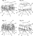
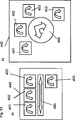
In einer bevorzugten Ausführungsform umfasst das Bedienelement Greiffinger, wobei die Greiffinger zu den Aussparungen in der Multititerplatte passen, was einem Formschluss entspricht (48, 49). Ein System zum Reinigen und Analysieren von Analyten ist des Weiteren offenbart, wobei das System eine Bearbeitungszelle umfasst, die eine Separationsstation zum Separieren eines Analyten, der in einem Behälter von einer Multititerplatte enthalten ist, von einem festen Trägermaterial. Diese Separationsstation ist vorzugsweise so gestaltet und angeordnet, dass ein Analyt, das in einem Behälter der Multititerplatte umfasst ist, von einem festen Trägermaterial separiert wird. Das System umfasst weiterhin eine Analysezelle, die eine Analysestation umfasst, wobei die Station einen Inkubator umfasst, um den Analyt zu bearbeiten, um ein Signal hinweisend auf das Vorhandensein oder Nichtvorhandensein des Analyten zu generieren. Zusätzlich umfasst das System mehr als ein Verbrauchsmaterial umfassend Öffnungen, wobei zumindest eine Öffnung an einer Seitenwand des Verbrauchsmaterials platziert ist und zumindest eine Öffnung an der gegenüberliegenden Seitenwand des Verbrauchsmaterials platziert ist. Ein Greifsystem, umfassend zumindest ein Bedienelement, ist ebenso von dem System umfasst, wobei zumindest ein Bedienelement zumindest einen Greiffinger an einer Seite des Bedienelements und zumindest ein Greiffinger an der gegenüberliegenden Seite des Bedienelements umfasst. Der Greiffinger interagiert mit den Öffnungen der Verbrauchsmaterialien und diese Wechselwirkung ist eine formschlüssige. Vorzugsweise umfasst das im Vorangegangen beschriebene System zusätzlich eine Probenzelle, die so gestaltet und angeordnet ist, dass eine Flüssigprobe von einem Probenbehälter zu einem Multititerbehälter transferiert wird. In einer bevorzugten Ausführungsform wird der Multititerbehälter zwischen Zellen mit Hilfe der Greifsystems transportiert. In einer weiteren bevorzugten Ausführungsform wird der Multititerbehälter von d er Probenzelle zu der Analysezelle transportiert. Bevorzugte Verbrauchsmaterialien sind hier beschrieben. Vorzugsweise umfasst mehr als ein Verbrauchsmaterial eine Multititerplatte und ein Spitzengestell.In a preferred embodiment, the operating element comprises gripping fingers, wherein the gripping fingers fit to the recesses in the multi-titre plate, which corresponds to a positive fit ( 48 . 49 ). A system for purifying and analyzing analytes is further disclosed, the system comprising a processing cell having a separation station for separating an analyte contained in a container from a multi-well plate from a solid support material. This separation station is preferably designed and arranged such that an analyte, which is contained in a container of the multi-titre plate, is separated from a solid carrier material. The system further comprises an analysis cell comprising an analysis station, the station comprising an incubator for processing the analyte to generate a signal indicative of the presence or absence of the analyte. In addition, the system includes more than one consumable material including openings wherein at least one opening is placed on a sidewall of the consumable and at least one opening is placed on the opposite sidewall of the consumable. A gripping system comprising at least one operating element is also included in the system, wherein at least one operating element comprises at least one gripping finger on one side of the operating element and at least one gripping finger on the opposite side of the operating element. The gripper finger interacts with the openings of the consumables and this interaction is a form-fitting. Preferably, the system described above additionally includes a sample cell configured and arranged to transfer a liquid sample from a sample container to a multi-liter container. In a preferred embodiment, the multi-liter container is transported between cells by means of the gripping system. In a further preferred embodiment, the multi-liter container is transported from the sample cell to the analysis cell. Preferred consumables are described herein. Preferably, more than one consumable includes a multi-well plate and a tip rack.

Ein bevorzugtes Bedienelement (500) umfasst einen zentralen Teil (500a), der mit einem Roboterarm (502) verbunden ist. Dieser zentrale Teil (500a) umfasst an zwei gegenüberliegenden Seiten Greiffinger (501). Diese Greiffinger (501) sind beweglich. Wenn sie mit dem Verbrauchsmaterial (60, 70, 101, 301, 302) umfassend Formschlusselemente (38, 106, 507, 309) zusammenwirken, wie im Vorangegangenen beschrieben, die Greiffinger verbinden dem Verbrauchsmaterial (60, 70, 101, 301, 302). Die Greiffinger (501) werden zu dem Verbrauchsmaterial (60, 70, 101, 301, 302) hinbewegt, greifen in X-Richtung mit den Fromschlusselementen (38, 106, 507, 309) ineinander, bis die Greiffinger (501) einen Stopp erreichen. In dieser Position existiert eine formschlüssige Position zwischen Bedienelement (500) und Verbrauchsmaterial (60, 70, 101, 301, 302). Das Bedienelement (500) verbunden mit dem Roboterarm (502) kann das Verbrauchsmaterial (60, 70, 101, 301, 302) von einer Position zu einer zweiten Position bewegen. Um das Verbrauchsmaterial (60, 70, 101, 301, 302) freizugeben, bewegen sich die Greifinger (501) weg von dem Verbrauchsmaterial (60, 70, 101, 301, 302). Vorzugsweise umfasst das Bedienelement federgelagerte Bolzen (506). Diese Bolzen (506) werden von dem Verbrauchsmaterial (60, 70, 101, 301, 302) abgedrängt, wenn das Bedienelement (500) an das Verbrauchsmaterieal (60, 70, 101, 301, 302) gedrückt wird. In dieser Position können die Greiffinger (501) mit den Formschlusselementen (38, 106, 507, 309) des Verbrauchsmaterials (60, 70, 101, 301, 302) interagieren. Bei Drücken des Bedienelementes (500) auf das Verbrauchsmaterial (60, 70, 101, 301, 302) können die Greiffinger (501) von den Formschlusselementen (38, 106, 507, 309) des Verbrauchsmaterials (60, 70, 101, 301, 302) wegbewegt werden (50a).A preferred operating element ( 500 ) comprises a central part ( 500a ), with a robotic arm ( 502 ) connected is. This central part ( 500a ) comprises on two opposite sides gripping fingers ( 501 ). These gripping fingers ( 501 ) are mobile. When using the consumables ( 60 . 70 . 101 . 301 . 302 ) comprising form-locking elements ( 38 . 106 . 507 . 309 ), as described in the foregoing, the gripper fingers connect the consumables ( 60 . 70 . 101 . 301 . 302 ). The gripping fingers ( 501 ) become consumables ( 60 . 70 . 101 . 301 . 302 ), engage in the X direction with the frictional elements ( 38 . 106 . 507 . 309 ) into each other until the gripper fingers ( 501 ) reach a stop. In this position exists a positive position between the control element ( 500 ) and consumables ( 60 . 70 . 101 . 301 . 302 ). The control element ( 500 ) connected to the robot arm ( 502 ) the consumable material ( 60 . 70 . 101 . 301 . 302 ) move from one position to a second position. To order the consumables ( 60 . 70 . 101 . 301 . 302 ), the Greifinger ( 501 ) away from the consumables ( 60 . 70 . 101 . 301 . 302 ). Preferably, the control element comprises spring-loaded bolts ( 506 ). These bolts ( 506 ) are consumed by the consumables ( 60 . 70 . 101 . 301 . 302 ) when the operating element ( 500 ) to the consumables ( 60 . 70 . 101 . 301 . 302 ) is pressed. In this position, the gripper fingers ( 501 ) with the form-locking elements ( 38 . 106 . 507 . 309 ) of the consumable material ( 60 . 70 . 101 . 301 . 302 ) to interact. When pressing the operating element ( 500 ) on the consumables ( 60 . 70 . 101 . 301 . 302 ), the gripper fingers ( 501 ) of the form-locking elements ( 38 . 106 . 507 . 309 ) of the consumable material ( 60 . 70 . 101 . 301 . 302 ) are moved away ( 50a ).

Das Bedienelement (500) umfasst auch Bolzen (507), die seitwärts an der Multititerplatte platziert sind, wenn das Bedienelement (500) nach unten auf das Verbrauchsmaterial (60, 70, 101, 301, 302) bewegt wird, bevor zugegriffen wird. Diese Bolzen (507) führen das Verbrauchsmaterial (60, 70, 101, 301, 302) in die korrekte Position zum Greifen. Weiterhin verhindern die Bolzen (507), dass das Verbrauchsmaterial (60, 70, 101, 301, 302) am Bedienelement (500) stecken bleibt, wenn die Greiffinger (501) sich weg von dem Verbrauchsmaterial (60, 70, 101, 301, 302) bewegen (50b).The control element ( 500 ) also includes bolts ( 507 ) placed sideways on the multi-well plate when the operating element ( 500 ) down on the consumables ( 60 . 70 . 101 . 301 . 302 ) is moved before being accessed. These bolts ( 507 ) carry the consumables ( 60 . 70 . 101 . 301 . 302 ) into the correct position for gripping. Furthermore, the bolts prevent 507 ) that the consumables ( 60 . 70 . 101 . 301 . 302 ) on the control element ( 500 ) gets stuck when the gripper fingers ( 501 ) away from the consumables ( 60 . 70 . 101 . 301 . 302 ) ( 50b ).

Vorzugsweise sind die Formschlusselemente (38, 106, 507, 309) als Öffnungen (38, 106, 507, 309) in den Seitenwänden des Verbrauchsmaterial, besonders bevorzugt an der langen Seite des Verbrauchsmaterials, ausgestaltet. Vorzugsweise sind zwei Öffnungen (38, 106, 507, 309) an einer Seitenwand platziert und zwei Öffnungen (38, 106, 507, 309) an der gegenüberliegenden Seitenwand platziert.Preferably, the positive-locking elements ( 38 . 106 . 507 . 309 ) as openings ( 38 . 106 . 507 . 309 ) in the sidewalls of the consumable, more preferably on the long side of the consumable. Preferably, two openings ( 38 . 106 . 507 . 309 ) is placed on one side wall and two openings ( 38 . 106 . 507 . 309 ) is placed on the opposite side wall.

Multititerplatte/BearbeitungsplatteMultiwell / handling plate

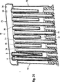
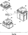
Eine Multititerplatte zum Inkubieren oder Separieren von Analyten wird offenbart. Multititerplatten werden vorzugsweise in Analysesystemen verwendet. Sie erlauben die parallele Separation und Analyse oder Aufbewahrung von einer Vielzahl von Proben. Multititerplatten können zur maximalen Flüssigkeitsaufnahme oder zum maximalen Wärmetransfer optimiert werden. Eine verbesserte Multititerplatte, die optimal zur Verwendung in automatisierten Analysesystemen ist, wird vorgestellt.A multi-well plate for incubating or separating analytes is disclosed. Multi-well plates are preferably used in analysis systems. They allow the parallel separation and analysis or storage of a variety of samples. Multititer plates can to the maximum Fluid intake or optimized for maximum heat transfer. An improved multi-titre plate, which is optimal for use in automated analysis systems, is presented.

Die Multititerplatte ist zur Inkubation oder Separation von Analyten in einem automatisierten Analysator optimiert. Vorzugsweise ist die Multititerplatte so gestaltet und angeordnet, um eine magnetische Vorrichtung und/oder eine Heizvorrichtung zu kontaktieren.The multi-well plate is optimized for incubation or separation of analytes in an automated analyzer. Preferably, the multi-well plate is configured and arranged to contact a magnetic device and / or a heater.

Die Multititerplatte umfasst:

  • – eine obere Fläche umfassend eine Vielzahl von Behältern mit Öffnungen an der Oberseite, die in Reihen angeordnet sind. Die Behälter umfassen einen oberen Teil, einen mittigen Teil und einen untern Teil. Der obere Teil ist mit der oberen Fläche der Multititerplatte verbunden und umfasst zwei längere und zwei kürzere Seiten. Der mittige Teil hat einen im Wesentlichen rechteckigen Querschnitt mit zwei langen Seiten und zwei kurzen Seiten;
  • – zwei gegenüberliegende kurz und zwei gegenüberliegende lange Seitenwände und
  • – eine Basis, wobei die Basis umfassend eine Öffnung gestaltet und angeordnet ist, die Multititerplatte in Kontakt mit einer magnetischen Vorrichtung und/oder einer Heizvorrichtung zu platzieren.
The multi-titre plate includes:
  • An upper surface comprising a plurality of containers with openings at the top arranged in rows. The containers comprise an upper part, a central part and a lower part. The upper part is connected to the upper surface of the multi-titre plate and comprises two longer and two shorter sides. The central part has a substantially rectangular cross-section with two long sides and two short sides;
  • - two opposite short and two opposite long side walls and
  • A base, wherein the base is formed including an opening and arranged to place the multi-well plate in contact with a magnetic device and / or a heater.

In einer bevorzugten Ausführungsform der Multititerplatte sind nebeneinander liegende Behälter innerhalb einer Reihe an der längeren Seite der fast rechteckigen Form verbunden.In a preferred embodiment of the multi-titre plate, adjacent containers are connected within a row on the longer side of the nearly rectangular shape.

Vorzugsweise umfasst die Multititerplatte einen kontinuierlichen Raum, der zwischen nebeneinanderliegenden Reihen von Behältern angeordnet ist. Dieser kontinuierliche Raum ist gestaltet und angeordnet, um eine plattenförmige, magnetische Vorrichtung aufzunehmen. In einer bevorzugten Ausführungsform umfasst der Bodenteil der Behälter einen sphärischen Boden. In einer besonders bevorzugten Ausführungsform umfasst das Bodenteil der Behälter einen konischen Teil, der zwischen dem mittigen Teil und dem sphärischen Bodenteil platziert ist.Preferably, the multi-titre plate comprises a continuous space arranged between adjacent rows of containers. This continuous space is designed and arranged to receive a plate-shaped magnetic device. In a preferred embodiment, the bottom part of the containers comprises a spherical bottom. In a particularly preferred embodiment, the bottom part of the containers comprises a conical part placed between the central part and the spherical bottom part.

In einer bevorzugten Ausführungsform umfasst die Oberseite Rippen, wobei die Rippen die Öffnungen der Behälter umgeben. Vorzugsweise umfasst eine kurze Seite des oberen Teils der Behälter eine Aussparung, wobei diese Aussparung eine gewölbte Fläche umfasst, die sich von der Rippe zu der Innenseite der Behälter erstreckt.In a preferred embodiment, the top comprises ribs, the ribs surrounding the openings of the containers. Preferably, a short side of the upper part of the containers comprises a recess, which recess comprises a curved surface extending from the rib to the inside of the containers.

Des Weiteren umfassen die Gefäße in einer bevorzugten Ausführungsform eine runde Innenseitenform.Furthermore, in a preferred embodiment, the vessels comprise a round inner side mold.

Zur Fixierung an den Prozess- oder Inkubationsstationen umfasst die Basis vorzugsweise einen Rand, der Aussparungen umfasst. Rasthaken an einer Station des Analysators können mit diesen Aussparungen einrasten, um die Platte an der Station zu fixieren.For fixation at the process or incubation stations, the base preferably includes a rim comprising recesses. Latching hooks on a station of the analyzer can engage with these recesses to fix the plate to the station.

In einer bevorzugten Ausführungsform umfassen die Gefäße eine im Wesentlichen konstante Wanddicke.In a preferred embodiment, the vessels comprise a substantially constant wall thickness.

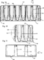
Die Verarbeitungsplatte (101) ist vorzugsweise eine ein-komponentige Platte. Die Oberseite (110) umfasst eine Vielzahl von Behältern (103) (28, 29). Jeder Behälter hat an der Oberseite eine Öffnung (108) und ist an der Bodenseite (112) geschlossen. Die Oberseite (110) umfasst Rippen (104), die relativ zu der Oberseite (110), vorzugsweise erhöht, angeordnet sind und die Öffnungen (108) der Behälter (103) umgeben. Dies beugt der Kontamination des Inhalts der Behälter (103) mit Tropfen von Flüssigkeit, die auf die Oberseite (110) der Platte (101) fallen können, vor. Ansichten einer bevorzugten Bearbeitungsplatte sind in 26 bis 37 gezeigt.The processing plate ( 101 ) is preferably a one-component plate. The top ( 110 ) comprises a plurality of containers ( 103 ) ( 28 . 29 ). Each container has an opening at the top ( 108 ) and is at the bottom side ( 112 ) closed. The top ( 110 ) includes ribs ( 104 ), which are relative to the top ( 110 ), preferably elevated, are arranged and the openings ( 108 ) the container ( 103 ) surround. This prevents contamination of the contents of the containers ( 103 ) with drops of liquid on top ( 110 ) of the plate ( 101 ). Views of a preferred machining plate are in 26 to 37 shown.

Die Stellfläche der Bearbeitungsplatte (101) umfasst vorzugsweise eine Länge und eine Breite der Basis, die zu dem ANSI SBS Stellflächenformat korrespondiert. Besonders bevorzugt ist eine Länge von 127, 76 mm +/– 0,25 mm und eine Breite von 85,48 mm +/– 0,25 mm. Somit hat die Platte (101) zwei gegenüberliegende kurze Seitenwände (109) und zwei gegenüberliegende lange Seitenwände (118). Die Bearbeitungsplatte (101) umfasst Formschlusselemente (106) zur Interaktion mit einem Bedienelement (500). Die Bearbeitungsplatte (101) kann mit hoher Geschwindigkeit schnell und sicher gegriffen, transportiert und positioniert werden, während die korrekte Orientierung und Position erhalten bleibt. Vorzugsweise sind die Formschlusselemente (106) zum Greifen innerhalb des oberen Bereichs des mittigen Teils vorgesehen, vorzugsweise dem oberen Bereich des mittigen Drittel der Bearbeitungsplatte (101). Dies hat den Vorteil, dass eine potentielle Verformung der Bearbeitungsplatte (101) nur einen geringen Effekt auf die Formschlusselemente (106) hat und dass die Handhabung der Platte (101) robuster ist.The footprint of the machining plate ( 101 ) preferably includes a length and a width of the base corresponding to the ANSI SBS footprint format. Particularly preferred is a length of 127, 76 mm +/- 0.25 mm and a width of 85.48 mm +/- 0.25 mm. Thus, the plate ( 101 ) two opposite short side walls ( 109 ) and two opposite long side walls ( 118 ). The processing plate ( 101 ) comprises positive-locking elements ( 106 ) for interaction with a control element ( 500 ). The processing plate ( 101 ) can be quickly and safely gripped, transported and positioned at high speed while maintaining the correct orientation and position. Preferably, the positive-locking elements ( 106 ) is provided for gripping within the upper region of the central part, preferably the upper region of the central third of the processing plate ( 101 ). This has the advantage that a potential deformation of the processing plate ( 101 ) only a slight effect on the form-locking elements ( 106 ) and that the handling of the plate ( 101 ) is more robust.

Die Bearbeitungsplatte (101) umfasst vorzugsweise Teilerkennungen (102) und (115). Die Teilerkennungen (102) und (115) sind für jede Bearbeitungsplatte (101) einzigartig und unterscheiden sich von Teilerkennungen von anderen Verbrauchsmaterialien, die für dasselbe System verwendet werden. Die Teilerkennungen (102, 115) umfassen vorzugsweise Stege (119) und/oder Aussparungen (125) an den Seitenwänden der Verbrauchsmaterialien, wobei die Struktur von Stegen (119) und/oder Aussparungen (125) einzigartig für den spezifischen Typ von Verbrauchsmaterial, vorzugsweise der Bearbeitungsplatte (101), ist. Diese einzigartige Struktur wird im vorliegenden Zusammenhang auch als einzigartige „Flächengeometrie” bezeichnet. Die Teilerkennungen (102, 115) stellen sicher, dass der Anwender die Bearbeitungsplatte (101) nur in die vorgesehene Stapelposition des Analyseinstruments (126) in der richtigen Orientierung laden kann. An den Seiten der Bearbeitungsplatte (101) sind Führungselemente (116) und (117) umfasst (33). Diese beugen einer Verkantung der Bearbeitungsplatte (101) vor. Die Führungselemente (116, 117) erlauben es, dem Anwender, die Bearbeitungsplatte (101) mit den Führungselementen (116, 117) als Stapel im Analyseinstrument zu laden, der dann vertikal innerhalb des Instrumentes in einem Stapel ohne Verkantung der Platten transferiert wird.The processing plate ( 101 ) preferably comprises part identifications ( 102 ) and (115). The part recognitions ( 102 ) and ( 115 ) are for each processing plate ( 101 ) and differ from part identifiers of other consumables used for the same system. The part recognitions ( 102 . 115 ) preferably include webs ( 119 ) and / or recesses ( 125 ) on the sidewalls of the consumables, the structure of webs ( 119 ) and / or recesses ( 125 ) unique for the specific type of consumables, preferably the processing plate ( 101 ) is. This unique structure is also referred to herein as a unique "surface geometry". The part recognitions ( 102 . 115 ) make sure that the user the machining plate ( 101 ) only in the intended stacking position of the analytical instrument ( 126 ) can load in the correct orientation. On the sides of the processing plate ( 101 ) are guiding elements ( 116 ) and ( 117 ) ( 33 ). These bend a canting of the processing plate ( 101 ) in front. The guide elements ( 116 . 117 ) allow the user, the processing board ( 101 ) with the guide elements ( 116 . 117 ) as a stack in the analytical instrument, which is then transferred vertically within the instrument in a stack without canting the plates.

Der mittige Teil (120) der Behälter (103) besitzt einen im Wesentlichen rechteckigen Querschnitt (30, 31). Diese sind entlang der längeren Seite (118) der im Wesentlichen rechteckigen Form durch eine gemeinsame Wand (113) separiert (37). Die Reihe von Behältern (103), die so geformt wird, hat den Vorteil, dass trotz des begrenzten Raumes, der zur Verfügung steht, diese ein großes Volumen haben, vorzugsweise ein Volumen von 4 ml. Ein anderer Vorteil ist, dass aufgrund der im Wesentlichen konstanten Wanddicke die Produktion sehr wirtschaftlich ist. Ein weiterer Vorteil ist, dass die Behälter (103) sich gegeneinander verstärken und so eine höhere Formstabilität erhalten werden kann.The central part ( 120 ) the container ( 103 ) has a substantially rectangular cross section ( 30 . 31 ). These are along the longer side ( 118 ) of substantially rectangular shape by a common wall ( 113 ) separated ( 37 ). The series of containers ( 103 ) that is formed has the advantage that, despite the limited space available, they have a large volume, preferably a volume of 4 ml. Another advantage is that, due to the substantially constant wall thickness, the production is very high is economical. Another advantage is that the containers ( 103 ) reinforce each other and so a higher dimensional stability can be obtained.

Zwischen den Reihen (123) von Behältern (103) ist eine kontinuierlicher Raum (121) vorgesehen (31, 35). Dieser Raum (121) kann Magneten (122) oder Heizvorrichtungen (128) aufnehmen (36, 38). Diese Magnete (122, 127) und Heizvorrichtungen (128) sind vorzugsweise massive Vorrichtungen. Somit können magnetische Teilchen (216), die in den Flüssigkeiten in den Behältern (103) enthalten sind, von der Flüssigkeit separiert werden, indem die Behälter (103) einem magentischen Feld ausgesetzt werden, wenn die Magnete (122, 127) in die Nähe der Behälter (103) gebracht werden.Between the rows ( 123 ) of containers ( 103 ) is a continuous space ( 121 ) intended ( 31 . 35 ). This room ( 121 ) can magnets ( 122 ) or heaters ( 128 ) take up ( 36 . 38 ). These magnets ( 122 . 127 ) and heaters ( 128 ) are preferably massive devices. Thus, magnetic particles ( 216 ) contained in the liquids in the containers ( 103 ) are separated from the liquid by the containers ( 103 ) are subjected to a magnetic field when the magnets ( 122 . 127 ) in the vicinity of the containers ( 103 ) to be brought.

Alternativ kann der Inhalt der Behälter (103) bei einer erhöhten, kontrollierten Temperatur inkubiert werden, wenn die Bearbeitungsplatte (101) auf der Heizvorrichtung (103) platziert wird. Da die Magneten (122, 127) oder die Heizvorrichtungen (128) massiv ausgebildet sein können, kann eine hohe Energiedichte erreicht werden. Die im Wesentlichen rechteckige Form des mittigen Teils (120) der Behälter (103) (siehe 36, 37) optimiert auch den Kontakt zwischen der Behälterwand (109) und einem flachen Magneten (122) oder der Heizvorrichtung (128) durch Optimierung der Kontaktfläche zwischen Behälter (103) und Magnet (122) oder Heizvorrichtung (128) und damit den Energietransfer in den Behälter (103) verbessert.Alternatively, the contents of the containers ( 103 ) are incubated at an elevated, controlled temperature when the processing plate ( 101 ) on the heater ( 103 ) is placed. Because the magnets ( 122 . 127 ) or the heaters ( 128 ) can be solid, a high energy density can be achieved. The substantially rectangular shape of the central part ( 120 ) the container ( 103 ) (please refer 36 . 37 ) also optimizes the contact between the container wall ( 109 ) and a flat magnet ( 122 ) or the heater ( 128 ) by optimizing the contact area between containers ( 103 ) and magnet ( 122 ) or heating device ( 128 ) and thus the energy transfer into the container ( 103 ) improved.

Im Bereich des konischen Bodens (111) der Behälter ist der Raum (121) noch stärker ausgeprägt und kann weitere Magnete (127) aufnehmen. Die Kombination der großen Magnete (122) in dem oberen Bereich und der kleineren Magnete (127) in dem konischen Bereich der Behälter (3), erlaubt die Trennung von magnetischen Teilchen (216) in großen oder kleinen Volumen von Flüssigkeit (215). Die kleinen Magnete (127) machen es somit einfacher, die magnetischen Teilchen (216) während der Eluat Pipettierung abzusondern. Dies ermöglicht es, das Eluat mit minimalem Verlust durch die Reduktion des Totvolumens von magnetischen Teilchen (216) Pellet (Niederschlag) zu pipettieren. Weiterhin ist das Vorhandensein von magnetischen Teilchen (216) in dem transferierten Eluat minimiert.In the area of the conical bottom ( 111 ) the container is the space ( 121 ) even more pronounced and can more magnets ( 127 ) take up. The combination of the big magnets ( 122 ) in the upper area and the smaller magnets ( 127 ) in the conical region of the containers ( 3 ), allows the separation of magnetic particles ( 216 ) in large or small volumes of liquid ( 215 ). The small magnets ( 127 ) make it easier to measure the magnetic particles ( 216 ) during the eluate segregate pipetting. This allows the eluate to be minimized by reducing the dead volume of magnetic particles ( 216 ) Pellet (precipitate) to pipette. Furthermore, the presence of magnetic particles ( 216 ) in the transferred eluate.

Am oberen Ende der Behälter (103) umfasst eine der kürzeren Seitenwände (109) des Behälters (103) einen Einlasskanal für Reagenzien (105), der sich bis zur voll umfänglichen Rippe (104) erstreckt (32, 30). Die Reagenzien werden auf den Einlasskanal (105) für Reagenzien pipettiert und laufen entlang des Kanals (105) in den Behälter (103) ab. Somit wird Kontakt zwischen der Pipettennadel (80) oder -spitze (3, 4) und der Flüssigkeit, die in dem Behälter enthalten ist, vorgebeugt. Weiterhin werden Spritzer, die vom Dosieren einer Flüssigkeit direkt in eine andere Flüssigkeit (215), die in den Behältern (103) enthalten ist, resultieren, was eine Kontamination der Pipettennadel (80) oder Spitze (3, 4) oder benachbarter Behälter (103) verursachen kann, vorgebeugt.At the upper end of the container ( 103 ) includes one of the shorter side walls ( 109 ) of the container ( 103 ) an inlet channel for reagents ( 105 ), which extends to the fully circumferential rib ( 104 ) ( 32 . 30 ). The reagents are placed on the inlet channel ( 105 ) are pipetted for reagents and run along the channel ( 105 ) in the container ( 103 ). Thus, contact between the pipette needle ( 80 ) or tip ( 3 . 4 ) and the liquid contained in the container is prevented. Furthermore, spatters that go from dosing a liquid directly into another liquid ( 215 ) contained in the containers ( 103 ), resulting in contamination of the pipette needle ( 80 ) or tip ( 3 . 4 ) or adjacent containers ( 103 ), prevent.

Sequentielle Pipettierung auf den Einlasskanal für Reagenzien (105) von kleinem Volumen von Reagenzien gefolgt von dem größten Volumen eines anderen Reagenz stellt sicher, dass die Reagenzien, die nur in kleinen Teilen zugesetzt werden, vollständig in den Behälter (103) ablaufen. Damit ist die Pipettierung von kleiner Volumen von Reagenzien möglich, ohne Verlust der Genauigkeit des Tests, der durchgeführt wird.Sequential pipetting to the inlet channel for reagents ( 105 ) of small volumes of reagents followed by the largest volume of any other reagent ensures that the reagents, which are added only in small portions, are completely contained in the container ( 103 ) expire. This makes it possible to pipette small volumes of reagents without sacrificing the accuracy of the test being performed.

An der Innenseite am Boden der Behälter (111), (112) wird die Formgebung konisch (111) und endet in einem sphärischen Boden (112) (34). Die Form der Innenseite des Behälters (114), beinhaltend den rechteckigen, mittigen Teil (120), ist abgerundet. Die Kombination des sphärischen Bodens (112), abgerundeter Innenseitenform (114), konischem Teil (111) und verfeinerte Fläche der Behälter (103) führt zu günstigen Strömungen, die eine effektive Separation und Reinigung von Analyten in der Bearbeitungsplatte (101) ermöglichen. Der sphärische Boden (112) erlaubt eine im Wesentlichen vollständige Verwendung von dem separierten Eluat und eine Reduktion des Totvolumens, was den Übertrag von Reagenzien oder Probenkreuzkontamination reduziert.On the inside at the bottom of the container ( 111 ) 112 ), the shaping becomes conical ( 111 ) and ends in a spherical bottom ( 112 ) ( 34 ). The shape of the inside of the container ( 114 ), including the rectangular, central part ( 120 ), is rounded. The combination of the spherical soil ( 112 ), rounded inside shape ( 114 ), conical part ( 111 ) and refined surface of the containers ( 103 ) leads to favorable flows that effectively separate and purify analytes in the processing plate ( 101 ) enable. The spherical soil ( 112 ) allows substantially complete use of the separated eluate and a reduction in dead volume, which reduces the carryover of reagents or sample cross-contamination.

Der Rand an der Basis (129) der Bearbeitungsplatte (101) umfasst Aussparungen (107) zum Einrasten von Rasthaken (124) an der Prozessstation (201) oder der Heizvorrichtung (128) oder dem Analyseinstrument (126) (28, 38, 39). Das Einrasten der Rasthaken (124) mit den Aussparungen (107) erlaubt die Positionierung und Fixierung der Bearbeitungsplatte (101) an der Prozessstation (201). Das Vorhandensein von den Aussparungen (107) ermöglicht es, dass die Kraft zum Einrasten auf die Bearbeitungsplatte (101) im Wesentlichen vertikal zu der Basis (129) wirkt. Somit können nur kleine Kräfte, die seitwärts wirken, entstehen. Dies reduziert das Vorkommen von Verformungen und damit eine Deformation der Bearbeitungsplatte (101). Die vertikalen Einrastkräfte können auch jegliche Deformationen der Bearbeitungsplatte (101) neutralisieren, was zu einer präzisieren Positionierung des sphärischen Bodens (111) innerhalb der Prozessstation (201) führt. Im Allgemeinen reduziert die präzise Schnittstelle zwischen der Bearbeitungsplatte (101) und der Prozessstation (201) oder der Heizvorrichtung (128) innerhalb des Analysators (126) die Totvolumina und auch das Risiko von Probenkreuzkontamination.The edge at the base ( 129 ) of the processing plate ( 101 ) includes recesses ( 107 ) for latching of latching hooks ( 124 ) at the process station ( 201 ) or the heater ( 128 ) or the analytical instrument ( 126 ) ( 28 . 38 . 39 ). The engagement of the locking hooks ( 124 ) with the recesses ( 107 ) allows the positioning and fixing of the processing plate ( 101 ) at the process station ( 201 ). The presence of the recesses ( 107 ) allows the force to snap onto the machining plate ( 101 ) substantially vertical to the base ( 129 ) acts. Thus, only small forces that act sideways, arise. This reduces the occurrence of deformations and thus a deformation of the processing plate ( 101 ). The vertical locking forces can also be any deformation of the machining plate ( 101 ), resulting in a more precise positioning of the spherical bottom ( 111 ) within the process station ( 201 ) leads. In general, the precise interface between the machining plate ( 101 ) and the process station ( 201 ) or the heater ( 128 ) within the analyzer ( 126 ) the dead volumes and also the risk of sample cross contamination.

Separationsstationseparation station

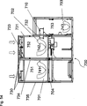
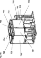
Eine Vorrichtung zur Separation eines Analyten gebunden an magnetischen Teilchen in einer Flüssigkeit, die in einem Behälter enthalten ist, wird offenbart. Die Vorrichtung umfasst eine Multititerplatte, die Behälter mit Öffnung an der Oberseite der Multititerplatte und geschlossenen Böden umfasst. Die Behälter umfassen einen oberen Teil, einen mittigen Teil und einen unteren Teil, wobei der obere Teil mit der Oberseite der Multititerplatte verbunden ist und vorzugsweise zwei längere und zwei kürzere Seiten umfasst. Der mittige Teil hat einen im Wesentlichen rechteckigen Querschnitt mit zwei längeren Seiten, wobei diese Behälter in Reihen aufgerichtet sind. Ein kontinuierlicher Raum ist zwischen zwei nebeneinander liegenden Reihen zur selektiven Kontaktierung mindestens eines Magneten vorgesehen, der an einer Fixierung mit der Seitenwand an zumindest zwei Z-Positionen befestigt ist. Die Vorrichtung umfasst weiterhin eine magnetische Separationsstation, die zumindest eine Fixierung umfasst. Die Fixierung umfasst zumindest einen Magneten, der ein Magnetfeld generiert. Ein Bewegungsmechanismus wird vorgesehen, um die zumindest eine Fixierung, die zumindest einen Magneten umfasst, in der Vertikalen zwischen zumindest einer ersten und einer zweiten Position im Bezug auf die Behälter der Multititerplatte zu bewegen. Vorzugsweise umfassen die zumindest zwei Z-Positionen der Behälter die Seitenwände und den unteren Teil dieser Behälter. Das Magnetfeld des zumindest einen Magneten zieht die magnetischen Teilchen vorzugsweise zu einer inneren Fläche der Behälter neben den zumindest einen Magneten, wenn der zumindest eine Magnet in der ersten Position ist. Der Effekt des Magnetfeldes ist im Vergleich zu dem zumindest einen Magneten in der ersten Position reduziert, wenn der Magnet in der zweiten Position ist. Vorzugsweise umfasst die Fixierung mit zumindest einem Magneten einen Rahmen. Die Behälter haben bevorzugte Merkmale, wie schon im Abschnitt Multititerplatte/Bearbeitungsplatte beschrieben. Ein solches bevorzugtes Merkmal ist, dass zumindest ein Teil der Behälter einen im Wesentlichen rechteckigen Querschnitt senkrecht zur Achse der Behälter aufweist.An apparatus for separating an analyte bound to magnetic particles in a liquid contained in a container is disclosed. The device comprises a multi-well plate comprising containers with openings at the top of the multi-well plate and closed trays. The containers comprise an upper part, a central part and a lower part, the upper part being connected to the upper side of the multi-titre plate and preferably comprising two longer and two shorter sides. The central part has a substantially rectangular cross-section with two longer sides, these containers being erected in rows. A continuous space is provided between two juxtaposed rows for selectively contacting at least one magnet fixed to a side wall fixation at at least two Z positions. The device further comprises a magnetic separation station comprising at least one fixation. The fixation comprises at least one magnet which generates a magnetic field. A movement mechanism is provided to move the at least one fixation comprising at least one magnet vertically between at least a first and a second position with respect to the containers of the multi-well plate. Preferably, the at least two Z-positions of the containers comprise the side walls and the lower part of these containers. The magnetic field of the at least one magnet preferably attracts the magnetic particles to an inner surface of the containers adjacent to the at least one magnet when the at least one magnet is in the first position. The effect of the magnetic field is reduced in the first position compared to the at least one magnet when the magnet is in the second position. The fixation with at least one magnet preferably comprises a frame. The containers have preferred features, as described in the section titled Multititerplatte / Bearbeitungsplatte. One such preferred feature is that at least a portion of the containers have a substantially rectangular cross-section perpendicular to the axis of the containers.

In der ersten Position befindet sich der zumindest eine Magnet neben diesem Teil dieser Behälter. Neben bedeutet in diesem Zusammenhang, entweder in der Nähe, so dass ein Magnetfeld auf den Inhalt der Behälter wirkt oder sich in körperlichem Kontakt mit dem Behälter befindet.In the first position, the at least one magnet is located adjacent to this part of these containers. Besides, in this context, means either nearby, so that a magnetic field acts on the contents of the containers or is in physical contact with the container.

Die Separationsstation umfasst einen Rahmen zur Aufnahme der Multititerplatte und Rasthaken zum Befestigen der Multititerplatte. Vorzugsweise umfasst die Separationsstation zwei Typen von Magneten. Diese bevorzugte Ausführungsform ist im Folgenden weiter beschrieben.The separation station comprises a frame for holding the multi-well plate and latching hooks for fastening the multi-well plate. Preferably, the separation station comprises two types of magnets. This preferred embodiment is further described below.

Eine zweite bevorzugte Ausführungsform ist im Folgenden beschrieben, wobei diese eine Feder umfasst, die einen Druck auf den Rahmen ausübt, der die Magneten umfasst, so dass die Magneten gegen die Behälter in der Multititerplatte gedrückt werden.A second preferred embodiment is described below, which comprises a spring which exerts a pressure on the frame comprising the magnets, so that the magnets are pressed against the containers in the multi-well plate.

Die ersten Magneten sind vorzugsweise gestaltet und angeordnet, um mit den Behältern einer Multititerplatte zum Anlegen eines Magnetfeldes an ein großes Volumen von Flüssigkeit, umfassend magnetische Teilchen, in den Behältern zu interagieren. Die zweiten Magneten sind vorzugsweise gestaltet und angeordnet, um mit den Behältern einer Multititerplatte zum Anlegen eines Magnetfeldes an ein kleines Volumen von Flüssigkeit, beinhaltend magnetische Teilchen, in den Behältern zu interagieren. Diese ersten und zweiten Magneten können zu verschiedenen Z-Positionen bewegt werden.The first magnets are preferably designed and arranged to interact with the containers of a multi-well plate for applying a magnetic field to a large volume of liquid comprising magnetic particles in the containers. The second magnets are preferably designed and arranged to interact with the containers of a multi-well plate to apply a magnetic field to a small volume of liquid, including magnetic particles, in the containers. These first and second magnets can be moved to different Z positions.

Ein Verfahren zur Isolation und Reinigung eines Analyten, vorzugsweise einer Nukleinsäure, wird beschrieben. Das Verfahren umfasst die Schritte zur Bindung des Analyten an magnetische Teilchen in einem Behälter einer Multititerplatte. Der Behälter umfasst eine obere Öffnung, einen mittigen Teil und einen unteren Teil. Das gebundene Material wird dann von dem ungebundenen Material separiert, das in der Flüssigkeit enthalten ist, wenn ein großer Teil der Flüssigkeit über dem Bereich liegt, wo der konische Teil des Behälters durch den mittigen Teil mit rechteckiger Form ersetzt wird. Dies geschieht durch Bewegen des Magneten von einer zweiten Position zu einer ersten Position und Anlegen eines Magnetfeldes in der ersten Position an dem mittigen Teil und optional zusätzlich Anlegen eines Magnetfeldes an dem Bodenteil des Behälters. Die magnetischen Teilchen können optional mit einer Waschlösung ausgewaschen werden. Ein kleines Flüssigkeitsvolumen, wobei ein Großteil der Flüssigkeit unter dem Bereich liegt, wo der konische Teil des Behälters ersetzt ist durch den mittigen Teil mit rechteckiger Form, wird von den magnetischen Teilchen durch selektives Anlegen eines Magnetfeldes an dem Bodenteil des Behälters separiert.A method for isolating and purifying an analyte, preferably a nucleic acid, is described. The method comprises the steps of binding the analyte to magnetic particles in a multi-well plate container. The container comprises an upper opening, a central part and a lower part. The bound material is then separated from the unbound material contained in the liquid when a large part of the Liquid is above the area where the conical part of the container is replaced by the central part of rectangular shape. This is done by moving the magnet from a second position to a first position and applying a magnetic field in the first position to the central part and optionally additionally applying a magnetic field to the bottom part of the container. The magnetic particles can optionally be washed out with a washing solution. A small volume of liquid, with most of the liquid below the area where the conical part of the container is replaced by the central part of rectangular shape, is separated from the magnetic particles by selectively applying a magnetic field to the bottom part of the container.

Das im Vorangegangenen beschriebene Verfahren umfasst vorzugsweise zusätzlich zwischen den Schritten c) und d) den Schritt des Elutierens von Nukleinsäure. Vorzugsweise umfasst das Verfahren den Schritt des Transferieren des Eluats von einer Multititerplatte zu einer zweiten Multititerplatte. In einer weiteren bevorzugten Ausführungsform wird ein erster Typ von Magnet von einer zweiten Position zu einer ersten Position im Schritt b) bewegt, um ein Magnetfeld an dem mittigen Teil des Behälters anzulegen, und optional wird ein zweiter Typ von Magnet bewegt, um an dem Bodenteil des Behälters ein Magnetfeld anzulegen. Besonders bevorzugt wird ein Magnet für Schritt b) zum mittigen Teil des Behälters bewegt, und der Magnet wird zum Bodenteil des Behälters in eine dritte Position zur Elutierung der Nukleinsäure bewegt.The method described above preferably additionally comprises the step of eluting nucleic acid between steps c) and d). Preferably, the method comprises the step of transferring the eluate from a multi-well plate to a second multi-well plate. In another preferred embodiment, a first type of magnet is moved from a second position to a first position in step b) to apply a magnetic field to the central part of the container, and optionally a second type of magnet is moved to the bottom part the container to create a magnetic field. Particularly preferably, a magnet for step b) is moved to the central part of the container, and the magnet is moved to the bottom part of the container in a third position for eluting the nucleic acid.

Eine magnetische Separationsstation zur Separation eines Analyten gebunden an magnetischen Teilchen wird beschrieben. Die Separationsstation umfasst erste Magneten, die gestaltet und angeordnet sind, um mit Behältern einer Multititerplatte zum Anlegen eines Magnetfeldes an ein großes Volumen von Flüssigkeit in diesen Behältern, enthaltend magnetische Teilchen, zu interagieren und zweite Magneten gestaltet und angeordnet, um mit Behältern einer Multititerplatte zum Anlegen eines Magnetfeldes an ein kleines Volumen von Flüssigkeit in den Behältern, umfassend magnetische Teilchen, zu interagieren, wobei die ersten und zweiten Magneten in verschiedene Z-Positionen bewegt werden können. Hier sind bevorzugte Ausführungsformen der magnetischen Separationsstation beschrieben.A magnetic separation station for separating an analyte bound to magnetic particles is described. The separation station includes first magnets configured and arranged to interact with containers of a multi-titre plate for applying a magnetic field to a large volume of liquid in these containers containing magnetic particles, and second magnets configured and arranged to communicate with containers of a multi-well plate Applying a magnetic field to a small volume of liquid in the containers, comprising magnetic particles, to interact, wherein the first and second magnets can be moved to different Z positions. Here, preferred embodiments of the magnetic separation station are described.

Eine erste bevorzugte Ausführungsform der Separationsstation (201) wird im Folgenden beschrieben. Die erste bevorzugte Ausführungsform der Separationsstation (201) umfasst zumindest zwei Typen von Magneten (202, 203). Der erste lange Typ von Magnet (202) ist gestaltet und angeordnet, um in den Raum (121) der Verarbeitungsplatte (101) zu passen. Magnet (202) generiert ein Magnetfeld an der Flüssigkeit (215) im Behälter (103), um die magnetischen Teilchen (216) an die Innenseite der Behälterseitenwand abzusondern. Das erlaubt das Separieren der magnetischen Teilchen (260) und jeglichem an diese gebundenes Material und der Flüssigkeit (215) innerhalb des Gefäßes (103), wenn ein großes Volumen von Flüssigkeit (205) vorhanden ist. Magnet (202) weist eine längliche Struktur auf und ist gestaltet und angeordnet, um mit dem im Wesentlichen rechteckigen, mittigen Teil (120) des Behälters zu interagieren. Somit wird der Magnet (202) verwendet, wenn sich ein Großteil der Flüssigkeit (215) über dem Bereich befindet, wo der konische Teil (111) des Behälters (103) durch den mittigen Teil mit rechteckiger Form ersetzt wird. Wie in 40 gezeigt, umfasst die bevorzugte Konstruktion der Magnete (202) Fixierungen (204, 204a), die Magnete (202) umfassen, die wiederum in den Raum (121) zwischen den Reihen von Behälter (103) in die Bearbeitungsplatte (101) passen. Eine weitere bevorzugte Ausführungsform der Magnete (202) umfasst Magnete (202), die an den Fixierungen (204, 204a) angeordnet sind. Die Magnete (203) der bevorzugten Separationsstation (201) sind kleiner und können mit dem konischen Teil (111) des Behälters (103) interagieren. Dies ist in 41(a) gezeigt. Die Magnete (203) sind vorzugsweise auf der Basis (205) angeordnet, die in den Raum (121) der Bearbeitungsplatte (101) bewegt werden kann. Jeder Magnet (202, 203) ist vorzugsweise gestaltet, um mit zwei Behältern (103) in zwei nebeneinander liegenden Reihen zu interagieren. In einer bevorzugten Ausführungsform weist die Bearbeitungsplatte (101) 6 Reihen mit 8 Behältern (103) auf. Eine Separationsstation (201), die mit der bevorzugten Verarbeitungsplatte (101) interagieren kann, weist drei Fixierungen (204, 204a), umfassend Magnete (202), und vier Basisteile (205), umfassend Magnete (203) auf. Eine weitere Ausführung ist auch umfasst, wobei die Separationsstation vier magnetische Fixierungen (204, 204a), umfassend Magneten (202), und drei magnetische Basisteile (205), umfassend Magnete (203), aufweist.A first preferred embodiment of the separation station ( 201 ) is described below. The first preferred embodiment of the separation station ( 201 ) comprises at least two types of magnets ( 202 . 203 ). The first long type of magnet ( 202 ) is designed and arranged to enter the room ( 121 ) of the processing plate ( 101 ) to fit. Magnet ( 202 ) generates a magnetic field on the liquid ( 215 ) in the container ( 103 ) to the magnetic particles ( 216 ) to the inside of the container sidewall. This allows the separation of the magnetic particles ( 260 ) and any material and liquid bound thereto ( 215 ) within the vessel ( 103 ), when a large volume of liquid ( 205 ) is available. Magnet ( 202 ) has an elongated structure and is designed and arranged to be connected to the substantially rectangular central part (FIG. 120 ) of the container to interact. Thus, the magnet ( 202 ) is used when a large part of the liquid ( 215 ) is located above the area where the conical part ( 111 ) of the container ( 103 ) is replaced by the central part of rectangular shape. As in 40 shows the preferred construction of the magnets ( 202 ) Fixations ( 204 . 204a ), the magnets ( 202 ), which in turn enter the room ( 121 ) between the rows of containers ( 103 ) in the processing plate ( 101 ) fit. A further preferred embodiment of the magnets ( 202 ) includes magnets ( 202 ) attached to the fixations ( 204 . 204a ) are arranged. The magnets ( 203 ) of the preferred separation station ( 201 ) are smaller and can with the conical part ( 111 ) of the container ( 103 ) to interact. This is in 41 (a) shown. The magnets ( 203 ) are preferably based ( 205 ) arranged in the room ( 121 ) of the processing plate ( 101 ) can be moved. Every magnet ( 202 . 203 ) is preferably designed to work with two containers ( 103 ) interact in two adjacent rows. In a preferred embodiment, the processing plate ( 101 ) 6 rows of 8 containers ( 103 ) on. A separation station ( 201 ) associated with the preferred processing plate ( 101 ) has three fixations ( 204 . 204a ), comprising magnets ( 202 ), and four basic parts ( 205 ), comprising magnets ( 203 ) on. A further embodiment is also included, wherein the separation station has four magnetic fixations ( 204 . 204a ), comprising magnets ( 202 ), and three magnetic bases ( 205 ), comprising magnets ( 203 ), having.

Die Magneten (202, 203) sind bewegbar. Die Separationsstation (201) umfasst einen Mechanismus, um die Fixierungen (204, 204a) und die Basisteile (205) zu bewegen. Alle Fixierungen (204, 204a) sind durch eine Basis (217) miteinander verbunden und sind somit in einer koordinierbaren Weise bewegbar. Alle Magnete (203) sind mit einer Basis (218) verbunden und somit in einer koordinierbaren Weise bewegbar. Der Mechanismus zum Bewegen der magnetischen Platten (202) und (203) ist gestaltet und angeordnet, um die zwei Typen von magnetischen Platten (202, 203) zu insgesamt vier Endpositionen zu bewegen:
In 40a–c sind die Magneten (203) in der Nähe des konischen Teils der Behälter (103) der Bearbeitungsplatte (101) platziert. Dies ist die oberste Position der Magneten (203) und entspricht der Separationspositon. In dieser Figur sind die Magneten (202) in der niedrigsten Position positioniert. Diese sind in dieser Position nicht an der Separation beteiligt.
The magnets ( 202 . 203 ) are movable. The separation station ( 201 ) comprises a mechanism for fixing ( 204 . 204a ) and the basic parts ( 205 ) to move. All fixations ( 204 . 204a ) are supported by a base ( 217 ) and are thus movable in a coordinatable manner. All magnets ( 203 ) are with a base ( 218 ) and thus movable in a coordinatable manner. The mechanism for moving the magnetic disks ( 202 ) and ( 203 ) is designed and arranged to accommodate the two types of magnetic disks ( 202 . 203 ) to a total of four end positions:
In 40a -C are the magnets ( 203 ) near the conical part of the containers ( 103 ) of the processing plate ( 101 ). This is the topmost position of the magnets ( 203 ) and corresponds to the Separationspositon. In this figure, the magnets ( 202 ) positioned in the lowest position. These are not involved in the separation in this position.

In 41a–c befinden sich die Magneten (202) und (203) in ihrer niedrigsten Position. Keiner der Magneten befindet sich in einer Separationsposition. Daher kann in dieser Position keine Separation von magnetischen Teilchen von der Flüssigkeit erfolgen.In 41a -C are the magnets ( 202 ) and ( 203 ) in their lowest position. None of the magnets is in a separation position. Therefore, no separation of magnetic particles from the liquid can take place in this position.

42a–c zeigen eine Position, in der die Magneten (202) sich in einem Raum (121) der Bearbeitungsplatte (101) befinden. Dies ist die oberste Z-Position der Magneten (202). In dieser Figur befinden sich auch die Magneten (203) in der obersten Z-Position. Diese legen ein magnetisches Feld an die Flüssigkeit im konischen Bereich der Behälter (103) an. Somit befinden sich beide Magnete in einer Separationsposition. Die oberste Z-Position der Magneten (202) und (203) sind somit unterschiedlich. 42a C show a position in which the magnets ( 202 ) in a room ( 121 ) of the processing plate ( 101 ) are located. This is the top Z position of the magnets ( 202 ). In this figure are also the magnets ( 203 ) in the top Z position. These apply a magnetic field to the liquid in the conical region of the containers ( 103 ) at. Thus, both magnets are in a separation position. The top Z position of the magnets ( 202 ) and ( 203 ) are different.

43a–c zeigen eine Position, in der sich die Magneten (202) in einem Raum (121) der Bearbeitungsplatte (101) befinden. Dies ist die oberste Position der Magneten (202) und stellt die Separationsposition dar. In dieser Figur befinden sich die Magneten (203) in der niedrigsten Position. Diese sind nicht an der Separation beteiligt, wenn sie sich in dieser Position befinden. 43a C show a position in which the magnets ( 202 ) in a room ( 121 ) of the processing plate ( 101 ) are located. This is the topmost position of the magnets ( 202 ) and represents the separation position. In this figure are the magnets ( 203 ) in the lowest position. These are not involved in the separation when in this position.

In den 40 bis 43 ist eine bevorzugte Ausührungsform gezeigt, wobei die Basis (217) der Magneten (202) dort mit einem Positionierrad (206) verbunden ist. Die Basis (217) umfasst ein unteres Ende (207), das in flexiblem Kontakt mit einem Kontaktelement (208) durch ein Bewegelement (209) steht. Das Bewegelement (209) ist gestaltet und angeordnet, um das Kontaktelement (208) entlang einer Schiene (212) von einer Seite zu der anderen zu bewegen. Das Bewegelement (209) ist an dem Kontaktelement (208) mit einem Pin (229) fixiert. Das Kontaktelement (208) ist an einem Positionierrad (206) mit einer Schraube (210) verbunden. Das Verbindungselement (208) ist mit der Achse (211) verbunden. Das Verbindungselement (208) ist vorzugsweise eine rechteckige Platte. Wenn sich das Positionierrad (206) exzentrisch um eine Achse (211) bewegt, bewegt sich die Schraube (210) von einem Punkt oberhalb der exzentrischen Achse zu einem Punkt unterhalb der exzentrischen Achse und bewegt sich das Bewegungselement (209) und das Bodenende (207) der Basis (204) mit den Magneten (202), die an dieser befestigt sind, von der obersten Position zu der untersten Position. Die Basis (218) ist an einem unteren Teil (219) befestigt und ist an ihrem unteren Ende mit einem Pin (213) mit einem Bewegelement (214) verbunden, welches vorzugsweise ein Rad darstellt, das mit dem Positionierrad (206) interagiert. Wenn das Positionierrad (206) sich um die Achse (211) dreht, bewegt sich das Rad (214) entlang des Positionierrades (206). Wenn das Rad (214) in einem Bereich des Positionierrades (206) angeordnet ist, wo die Distanz zu der Achse (211) kurz ist, befinden sich die Magneten (203) in ihrer niedrigsten Position. Wenn Rad (214) im Bereich des Positionierrades (206) angeordnet ist, wo die Distanz zu der Achse (211) maximal ist, befinden sich die Magneten (203) in ihrer obersten Position. Somit ist die Position der Magneten (203) in der bevorzugten Ausführungsform der ersten Ausführungsform der Separationsstation durch die Gestalt des Positionierrades (206) kontrolliert. Wenn sich Bewegungselement (209) entlang des mittigen, abgerundeten, oberen oder unteren Teils (212a) der Schiene (212) bewegt, wird der kleine Typ von Magneten (203) hoch und runter bewegt. Wenn Bewegelement (209) an der Seite (212b) am unteren Ende (207) angeordnet ist und sich hoch und runter bewegt, werden die Magneten (202) nach oben und unten bewegt. Das Positionierrad (206) kann durch einen jedem Motor (224) rotiert werden.In the 40 to 43 a preferred embodiment is shown, wherein the base ( 217 ) of magnets ( 202 ) there with a positioning wheel ( 206 ) connected is. The base ( 217 ) comprises a lower end ( 207 ) which is in flexible contact with a contact element ( 208 ) by a moving element ( 209 ) stands. The moving element ( 209 ) is designed and arranged to the contact element ( 208 ) along a rail ( 212 ) to move from one side to the other. The moving element ( 209 ) is on the contact element ( 208 ) with a pin ( 229 ) fixed. The contact element ( 208 ) is on a positioning wheel ( 206 ) with a screw ( 210 ) connected. The connecting element ( 208 ) is with the axis ( 211 ) connected. The connecting element ( 208 ) is preferably a rectangular plate. When the positioning wheel ( 206 ) eccentrically about an axis ( 211 ), the screw moves ( 210 from a point above the eccentric axis to a point below the eccentric axis, and the moving element ( 209 ) and the bottom end ( 207 ) the base ( 204 ) with the magnets ( 202 ), which are attached to this, from the uppermost position to the lowest position. The base ( 218 ) is at a lower part ( 219 ) and is at its lower end with a pin ( 213 ) with a moving element ( 214 ), which is preferably a wheel connected to the positioning wheel ( 206 ) interacts. When the positioning wheel ( 206 ) around the axis ( 211 ), the wheel moves ( 214 ) along the positioning wheel ( 206 ). When the wheel ( 214 ) in a region of the positioning wheel ( 206 ), where the distance to the axis ( 211 ) is short, the magnets ( 203 ) in their lowest position. If wheel ( 214 ) in the region of the positioning wheel ( 206 ), where the distance to the axis ( 211 ) is maximum, the magnets are ( 203 ) in its uppermost position. Thus, the position of the magnets ( 203 ) in the preferred embodiment of the first embodiment of the separation station by the shape of the positioning wheel ( 206 ) controlled. When moving element ( 209 ) along the central, rounded, upper or lower part ( 212a ) of the rail ( 212 ), the small type of magnet ( 203 ) moves up and down. When moving element ( 209 ) on the side ( 212b ) at the lower end ( 207 ) and moves up and down, the magnets ( 202 ) moves up and down. The positioning wheel ( 206 ) can by any engine ( 224 ) are rotated.

In einer bevorzugten Ausführungsform wird eine Feder (225) zu der Basis (222) der Separationsstation befestigt und die Basis (218) der Magneten (203), um sicher zu stellen, dass die Magneten (203) in die niedrigste Position bewegt werden, wenn sie nach unten bewegt werden.In a preferred embodiment, a spring ( 225 ) to the base ( 222 ) of the separation station and the base ( 218 ) of magnets ( 203 ) to make sure that the magnets ( 203 ) are moved to the lowest position when they are moved down.

Die Bezeichnung „Pin” bezieht sich auf jedes beliebige Fixierungselement wie beispielsweise Schrauben oder Stifte.The term "pin" refers to any fixing element such as screws or pins.

In einer zweiten bevorzugten Ausführungsform umfasst die Separationsstation (230) zumindest eine Fixierung (231), die zumindest einen Magneten (232) umfasst, vorzugsweise eine Anzahl von Magneten, die gleich der Anzahl von Behältern (103) in einer Reihe (123) ist. Vorzugsweise umfasst die Separationsstation (230) eine Anzahl von Fixierungen (231), die gleich der Anzahl von Reihen (123) in der Multititerplatte (101), wie im vorangegangen beschrieben ist. Besonders bevorzugt werden sechs Fixierungselemente (231) an der Separationsstation (230) befestigt. Zumindest ein Magnet (232) wird auf einer Fixierung (231) befestigt. Vorzugsweise entspricht die Anzahl von Magneten (232) der Anzahl von Behälter (103) in eine Reihe (123). Besonders bevorzugt werden 8 Magneten (232) an einer Fixierung (231) befestigt. Vorzugsweise ist ein Typ des Magneten (232) an dieser Fixierung (231) umfasst. Besonders bevorzugt wird der Magnet (232) an einer Seite befestigt, die zu den Behältern hin ausgerichtet ist, mit denen der Magnet interagiert.In a second preferred embodiment, the separation station comprises ( 230 ) at least one fixation ( 231 ), which has at least one magnet ( 232 ), preferably a number of magnets equal to the number of containers ( 103 ) in a row ( 123 ). Preferably, the separation station comprises ( 230 ) a number of fixations ( 231 ) equal to the number of rows ( 123 ) in the multi-bit plate ( 101 ), as described above. Particularly preferred are six fixing elements ( 231 ) at the separation station ( 230 ) attached. At least one magnet ( 232 ) is placed on a fixation ( 231 ) attached. Preferably, the number of magnets ( 232 ) the number of containers ( 103 ) in a row ( 123 ). Particularly preferred are 8 magnets ( 232 ) on a fixation ( 231 ) attached. Preferably, one type of magnet ( 232 ) on this fixation ( 231 ). Particularly preferred is the magnet ( 232 ) is attached to a side that is aligned with the containers with which the magnet interacts.

Die Fixierung (231) ist an einer Basis (233) befestigt. Vorzugsweise ist die Befestigung flexibel. Die Basis (233) umfasst Federn (234), die darauf befestigt sind. Die Anzahl der Federn (234) umfasst zumindest eine Feder pro Fixierung (231), die auf der Basis (233) befestigt ist. Die Basis umfasst des Weiteren eine Abschrägung (236), die die Bewegung der Feder und demzufolge der Fixierung (231) umfassend die Magneten (232) begrenzt. Vorzugsweise ist eine der Federn (234) gestaltet und angeordnet, um mit einer Fixierung (231) zu interagieren. Besonders bevorzugt ist die Feder (234) als ein Federbügel ausgestaltet. Diese Interaktion kontrolliert die horizontale Bewegung der Fixierungen (231). Weiterhin umfasst die Separationsstation (230) einen Rahmen (235). Die Basis (233) mit Fixierungen (231) ist mit dem Rahmen (235) durch einen, wie im Vorangegangenen beschriebenen, Bewegungsmechanismus der Magneten (232) der ersten Ausführungsform verbunden.The fixation ( 231 ) is at a base ( 233 ) attached. Preferably, the attachment is flexible. The base ( 233 ) includes springs ( 234 ) attached to it. The number of springs ( 234 ) comprises at least one spring per fixation ( 231 ), on the base ( 233 ) is attached. The base further includes a bevel ( 236 ), the movement of the spring and, consequently, the fixation ( 231 ) comprising the magnets ( 232 ) limited. Preferably, one of the springs ( 234 ) and arranged to provide a fixation ( 231 ) to interact. Particularly preferred is the spring ( 234 ) designed as a spring clip. This interaction controls the horizontal movement of the fixations ( 231 ). Furthermore, the separation station ( 230 ) a frame ( 235 ). The base ( 233 ) with fixations ( 231 ) is with the frame ( 235 ) by a, as described above, moving mechanism of the magnets ( 232 ) of the first embodiment.

Vorzugsweise sind die Basis (233) und die Fixierung (231) so gestaltet und angeordnet, dass diese sich in der Vertikalen bewegen (in Z-Richtung).Preferably, the base ( 233 ) and the fixation ( 231 ) are designed and arranged so that they move vertically (in the Z direction).

Die Multititerplatte (101), wie im Vorangegangenen beschrieben, wird in der Separationsstation (230) aufgenommen. Die Fixierung (231), umfassend die Magneten (232), ist in der Vertikalen bewegbar. Jede der Fixierungen (231) wird so in einem Raum (121) zwischen zwei Reihen (123) von Behältern (103) bewegt. Die vertikale Bewegung bringt die Magneten (232), befestigt an der Fixierung (231), in Kontakt mit den Behältern (103). Die Z-Position wird abhängig von dem Volumen von Flüssigkeit (215) in den Behältern (103) gewählt. Für große Volumina kontaktieren die Magneten (232) die Behälter (103) in einer mittigen Position (120), wo die Behälter (103) eine im Wesentlichen rechteckige Form aufweisen. Für kleine Volumina von Flüssigkeit (215), wo sich ein Großteil der Flüssigkeit (215) unter dem mittigen Teil (120) der Behälter (103) befindet, kontaktieren die Magneten (232) vorzugsweise den konischen Teil (111) der Behälter (103).The multi-bit plate ( 101 ), as described above, in the separation station ( 230 ). The fixation ( 231 ), comprising the magnets ( 232 ), is vertically movable. Each of the fixations ( 231 ) is so in a room ( 121 ) between two rows ( 123 ) of containers ( 103 ) emotional. The vertical movement brings the magnets ( 232 ), attached to the fixation ( 231 ), in contact with the containers ( 103 ). The Z position is dependent on the volume of liquid ( 215 ) in the containers ( 103 ). For large volumes, contact the magnets ( 232 ) the containers ( 103 ) in a central position ( 120 ), where the containers ( 103 ) have a substantially rectangular shape. For small volumes of liquid ( 215 ), where much of the liquid ( 215 ) under the central part ( 120 ) the container ( 103 ), the magnets ( 232 ) preferably the conical part ( 111 ) the container ( 103 ).

Eine Feder ist mit der Basis (233) jedem der Rahmens (231) verbunden (39a), b)). Die Feder drückt die Magneten (232) gegen die Behälter (103). Dies stellt einen Kontakt zwischen den Magneten (232) und den Behälter (103) während der magnetischen Separation sicher. Vorzugsweise kontaktiert der Magnet (232) den Behälter (103) an der Seitenwand (109), die unterhalb des Einlasses (105) angeordnet ist. Dies hat den Vorteil, dass die Flüssigkeit, die durch den Pipettierstöme über die abgesonderten magnetischen Teilchen zugeführt werden und stellt sicher, dass die Teilchen wieder verteilt werden und dass alle Proben in allen Behältern gleich behandelt werden.A spring is with the base ( 233 ) each of the frames ( 231 ) connected ( 39a) , b)). The spring pushes the magnets ( 232 ) against the containers ( 103 ). This places a contact between the magnets ( 232 ) and the container ( 103 ) during the magnetic separation. Preferably, the magnet contacts ( 232 ) the container ( 103 ) on the side wall ( 109 ) located below the inlet ( 105 ) is arranged. This has the advantage that the liquid supplied by the pipetting streams through the separated magnetic particles ensures that the particles are redistributed and that all samples in all containers are treated the same.

Diese Ausführungsform ist besonders geeignet zur Separation einer Flüssigkeit (215), die in einer Multititerplatte (101) enthalten ist, wie im Vorangegangenen beschrieben, von magnetischen Teilchen (216), wenn unterschiedliche Ebenen von der Flüssigkeit (216) in den Behältern (103) der Multititerplatte (101) enthalten sind.This embodiment is particularly suitable for separating a liquid ( 215 ) stored in a multi-well plate ( 101 ), as described above, of magnetic particles ( 216 ), if different levels of the liquid ( 216 ) in the containers ( 103 ) of the multi-bit plate ( 101 ) are included.

AD Platte und RahmenAD plate and frame

Zur Amplifikation und Detektion werden üblicherweise Multititerplatten verwendet. Solche Platten sind besonders nützlich in automatisierten Analysesystemen, die eine Amplifikationsstation zur Amplifikation von Nukleinsäure-Analyten umfassen.For amplification and detection usually multi-well plates are used. Such plates are particularly useful in automated analysis systems that include an amplification station for amplifying nucleic acid analytes.

Um Kontamination zwischen den Vertiefungen vor, während und nach der Amplifikationsreaktion zu vermeiden, sind die Reaktionsbehälter, in welchen die Amplifikation stattfindet, abgedichtet. Eine übliche Weise zur Abdichtung der Amplifikation-Multititerplatte umfasst das Vorsehen einer Dichtfolie auf der Platte und Verbinden mit der Platte, entweder mittels Klebe- oder Heißdichtung.In order to avoid contamination between the wells before, during and after the amplification reaction, the reaction vessels in which the amplification takes place are sealed. A common way to seal the amplification multi-well plate involves providing a sealing film on the plate and bonding to the plate, either by adhesive or hot sealing.

Ein verbessertes, automatisiertes Verfahren zur Isolation und Amplifikation einer Nukleinsäure mit verbesserter Multititerplatte mit einer Dichtfolie und verbessertem, automatisiertem Analysesystem werden hier beschrieben.An improved, automated method for isolating and amplifying an improved multi-well plate nucleic acid with a sealing foil and an improved, automated analysis system are described here.

Ein Verfahren zur Isolation und Amplifikation eines Nukleinsäure-Analyten, der in einer Flüssigprobe enthalten ist, wird beschrieben. Das Verfahren umfasst das Separieren des Nulkleinsäure-Analyts von anderen Materialien, die in der Flüssigprobe in einem ersten Behälter vorhanden sind. Vorzugsweise ist der erste Behälter in einer ersten Multititerplatte umfasst. Eine zweite Multititerplatte wird zur Verfügung gestellt. Diese zweite Multititerplatte umfasst einen Deckel, der einen Rahmen und eine Dichtfolie umfasst. Der Deckel wird angehoben und das separierte Analyt in dem ersten Behälter wird zu einer Vertiefung der zweiten Multititerplatte transferiert. Der Deckel, umfassend die Dichtfolie, wird auf der zweiten Multititerplatte platziert. Somit ist die zweite Multititerplatte mit der Dichtfolie abgedichtet. Wenn die zweite Multititerplatte abgedichtet ist, wird das Analyt in der Anwesenheit von Amplifikationsreagenzien, die schon vor Abdichten zugegeben wurden, in der zweiten Multititerplatte amplifiziert.A method for isolating and amplifying a nucleic acid analyte contained in a liquid sample is described. The method comprises separating the nucleic acid analyte from other materials present in the liquid sample in a first container. Preferably, the first container is included in a first multi-liter plate. A second multi-well plate is provided. This second multi-well plate comprises a lid comprising a frame and a sealing foil. The lid is lifted and the separated analyte in the first container is transferred to a well of the second multi-well plate. The lid, comprising the sealing foil, is placed on the second multi-well plate. Thus, the second multi-well plate is sealed with the sealing film. When the second multi-well plate is sealed, the analyte is amplified in the presence of amplification reagents added prior to sealing in the second multi-well plate.

In einer bevorzugten Ausführungsform des Schritts b) befindet sich der Deckel auf der zweiten Multititerplatte in einer ersten Position, wobei die erste Position den Kontakt zwischen der Dichtfolie und der Multititerplatte vermeidet; und in Schritt e) befindet sich der Deckel auf der zweiten Multititerplatte in einer zweiten Position, wobei die zweite Position den Kontakt zwischen der Dichtfolie und der Multititerplatte herstellt.In a preferred embodiment of step b), the lid is located on the second multi-well plate in a first position, the first position avoiding contact between the sealing foil and the multi-titre plate; and in step e), the lid on the second multi-well plate is in a second position, the second position making contact between the sealing foil and the multi-titre plate.

In einer bevorzugten Ausführungsform des Verfahrens, wie im Vorangegangenen beschrieben, wird der Deckel um 180° gedreht.In a preferred embodiment of the method, as described above, the lid is rotated by 180 °.

Vorzugsweise umfasst der Rahmen Stützrippe, besonders bevorzugt vier Stützrippen, und die Multititerplatte umfasst die korrespondierenden Aussparungen, besonders bevorzugt vier korrespondierende Aussparungen, wobei die Aussparungen so positioniert sind, dass die Stützrippen des Rahmens nicht mit den Aussparungen in der ersten Position des Deckels auf der Multititerplatte ausgerichtet sind und dass die Stützrippen in der zweiten Position des Deckels der Multititerplatte mit den Aussparungen ausgerichtet sind. Preferably, the frame comprises support rib, more preferably four support ribs, and the multi-well plate comprises the corresponding recesses, more preferably four corresponding recesses, wherein the recesses are positioned so that the support ribs of the frame not with the recesses in the first position of the lid on the multi-well plate are aligned and that the support ribs are aligned in the second position of the lid of the multi-well plate with the recesses.

In der zweiten Position werden die Stützrippen des Rahmens vorzugsweise in den Aussparungen der Multititerplatte platziert.In the second position, the support ribs of the frame are preferably placed in the recesses of the multi-well plate.

In einer bevorzugten Ausführungsform des hier beschriebenen Verfahrens stellt die Abdichtung in Schritt f) eine Heißdichtung dar. Weitere bevorzugte Ausführungsformen des Verfahrens sind im Vorangegangenen oder im Folgenden beschrieben.In a preferred embodiment of the method described here, the seal in step f) constitutes a hot seal. Further preferred embodiments of the method are described above or below.

Ein Multititerplatten-Set umfassend eine Multititerplatte und einen Deckel werden beschrieben, wobei der Deckel einen Rahmen und eine Dichtfolie, die am Rahmen fixiert ist, umfasst, wobei in einer ersten Position des Deckels auf der Multititerplatte eine Trennabstand zwischen der Dichtfolie und der oberen Fläche der Multititerplatte vorhanden ist und in einer zweiten Position die Dichtfolie in Kontakt mit der Oberseite der Multititerplatte steht. Vorzugsweise umfasst der Rahmen Stützrippen und die Multititerplatte umfasst Öffnungen, wobei in der ersten Position die Stützrippen in einer anderen Lage als die Öffnungen sind und in der zweiten Position die Stützrippen und die Öffnungen miteinander ausgerichtet sind. In einer bevorzugten Ausführungsform des Multititerplatten-Sets, wie hier beschrieben, umfasst die Oberseite der Multititerplatte Heizstege, wobei in der zweiten Position die Abdichtfolie die Heizstege kontaktiert. Vorzugsweise ist die Dichtfolie an dem Rahmen durch ein Heißdichtungsverfahren fixiert. Besonders bevorzugt wird die Dichtfolie an der Oberseite des Rahmens fixiert. In einer bevorzugten Ausführungsform umfasst die Dichtfolie ein Polymer. Vorzugsweise umfasst die Dichtfolie zumindest zwei Schichten mit unterschiedlichen Schmelzpunkten. Besonders bevorzugt umfasst die Dichtfolie zwei Schichten mit unterschiedlichen Schmelzpunkten, wobei die Schicht mit dem geringeren Schmelzpunkt zur Multititerplatte hin orientiert ist. Weitere bevorzugte Ausführungsformen des Verfahrens sind im Vorangegangenen und im Folgenden beschrieben.A multi-well plate set comprising a multi-well plate and a lid is described, the lid comprising a frame and a sealing foil fixed to the frame, wherein in a first position of the lid on the multi-well plate a separation distance between the sealing foil and the upper surface of the Multititerplatte is present and in a second position, the sealing film is in contact with the top of the multi-well plate. Preferably, the frame comprises support ribs and the multi-well plate comprises openings, wherein in the first position the support ribs are in a different position than the openings and in the second position the support ribs and the openings are aligned with each other. In a preferred embodiment of the multi-well plate set, as described here, the upper side of the multi-well plate comprises heating ribs, wherein in the second position the sealing foil contacts the heating ribs. Preferably, the sealing film is fixed to the frame by a heat sealing method. Particularly preferably, the sealing film is fixed to the upper side of the frame. In a preferred embodiment, the sealing film comprises a polymer. Preferably, the sealing film comprises at least two layers with different melting points. Particularly preferably, the sealing film comprises two layers with different melting points, wherein the layer with the lower melting point is oriented toward the multi-well plate. Further preferred embodiments of the method are described above and below.

Ein analytisches System umfassend eine Haltestation und eine Multititerplatte, wie hier beschrieben, ist auch offenbart, wobei die Multititerplatte in der Haltestation fixiert ist.An analytical system comprising a holding station and a multi-well plate as described herein is also disclosed wherein the multi-well plate is fixed in the holding station.

Vorzugsweise umfasst das analytische System zusätzlich eine Dichtstation, um Heizdichten der Dichtfolie auf dem Rahmen der Multititerplatte auszuführen. Vorzugsweise umfasst die Multititerplatte eine Basis mit einem Steg, der Aussparungen umfasst, wobei ein Positionierungs- und Fixierungselement an der Haltestation die Aussparungen kontaktiert, wobei der Kontakt einen nach unten gerichteten Druck auf die Basis der Multititerplatte ausübt, und die Multititerplatte dadurch in der Haltestation fixiert.Preferably, the analytical system additionally comprises a sealing station to carry out heating densities of the sealing film on the frame of the multi-titre plate. Preferably, the multi-well plate comprises a base having a land including recesses, a positioning and fixing element contacting the recesses at the holding station, the contact exerting a downward pressure on the base of the multi-well plate and thereby fixing the multi-well plate in the holding station ,

Die beispielhafte Multititerplatte mit einem Rahmen umfasst eine Multititerplatte (300), die eine Vielzahl von Behältern (312) umfasst. Die Behälter (312) sind integral an der oberen Fläche (326) der Multititerplatte (301) ausgebildet. Die obere Fläche (326) ist jedes Behälters (312) von einem erhöhten Heizsteg (311) umgeben. Der Deckel (302) umfasst einen Rahmen (302b), umfassend ein Polymer (314), und eine Folie (303), umfassend ein Polymer. Die Folie (303) ist an dem Rahmen (302b) durch Heißdichtungsverfahren fixiert. Vorzugsweise wird die Folie (303) auf der oberen Fläche (302a) abgedichtet, besonders bevorzugt mittels Heißdichten.The exemplary multi-well plate with a frame comprises a multi-bit plate ( 300 ), which contain a large number of containers ( 312 ). The containers ( 312 ) are integral to the upper surface ( 326 ) of the multi-bit plate ( 301 ) educated. The upper surface ( 326 ) is each container ( 312 ) from an elevated heating bar ( 311 ) surround. The lid ( 302 ) includes a frame ( 302b ) comprising a polymer ( 314 ), and a foil ( 303 ) comprising a polymer. The foil ( 303 ) is on the frame ( 302b ) fixed by heat sealing method. Preferably, the film ( 303 ) on the upper surface ( 302a ), more preferably by means of hot densities.

Die Multititerplatte (300) umfasst zwei lange Seitenwände (323, 324), die einander gegenüberliegen, und zwei kurze Seitenwände (319, 320), die einander gegenüberliegen. Der Rahmen (302b) umfasst zwei lange Seitenwände (328, 327), die einander gegenüberliegend platziert sind, und zwei kurze Seitenwände (321, 322), die einander gegenüberliegend platziert sind.The multi-bit plate ( 300 ) comprises two long side walls ( 323 . 324 ), which are opposite each other, and two short side walls ( 319 . 320 ), which are opposite each other. The frame ( 302b ) comprises two long side walls ( 328 . 327 ), which are placed opposite each other, and two short side walls ( 321 . 322 ) placed opposite each other.

Die bevorzugte Folie (303) umfasst zwei Schichten (314, 315) mit unterschiedlichen Schmelzpunkten. Eine Schicht (311) hat einen niedrigeren Schmelzpunkt. Diese Schicht (311) ist zu der Multititerplatte (301) mit den Heizstegen (310, 311) und der Fläche (302a) des Rahmens (302b) orientiert. Während des Heizdichtens wird Hitze durch die stabilere Schicht (310) mit dem höheren Schmelzpunkt zu der Schicht (311) mit dem niedrigeren Schmelzpunkt transferiert. Schicht (311) wird somit erhitzt und geschmolzen. Die obere Schicht (310) wird während des Heizdichtens nicht geschmolzen. Dies minimiert das Risiko von Undichtigkeiten in der Folie (303) (45b)).The preferred film ( 303 ) comprises two layers ( 314 . 315 ) with different melting points. A layer ( 311 ) has a lower melting point. This layer ( 311 ) is to the multi-bit plate ( 301 ) with the heating bars ( 310 . 311 ) and the surface ( 302a ) of the frame ( 302b ) oriented. During the heat-sealing, heat is generated by the more stable layer ( 310 ) with the higher melting point to the layer ( 311 ) with the lower melting point. Layer ( 311 ) is thus heated and melted. The upper layer ( 310 ) is not melted during the heat sealing. This minimizes the risk of leaks in the film ( 303 ) ( 45b) ).

Die Multititerplatte (301) und der Deckel (302) sind paarweise (300) zur Bereitstellung montiert. An der Innenseite (316) der oberen Seite (317) umfasst der Rahmen (302b) Stützrippen (318). Zwei Stützrippen (318) sind entlang der ersten Seitenwand (321) des Rahmens (302b) vorgesehen und zwei Stützrippen (318) sind entlang der zweiten Seitenwand (322) der ersten Seitenwand (319) gegenüberliegend vorgesehen. Vorzugsweise stellen die Seitenwände die kurzen Seitenwände des Rahmens (302b) dar. Die Kante der oberen Fläche (313) der Multititerplatte (301) umfasst Öffnungen (308). Die Öffnungen (308) sind entlang Seitenwänden (319, 320) korrespondierend zu den Seitenwänden des Rahmens (321, 322) vorgesehen, wo die Stützrippen (318) vorgesehen sind. Die Zusammenbau-Beschickungsposition des Deckels (302) relativ zu der Multititerplatte (301) (44a) werden die Öffnungen (308) so angeordnet, dass sie nicht mit den Stützrippen (318) ausgerichtet sind. Somit, wenn der Deckel (302) auf der Multititerplatte (301) platziert wird, sitzen die Stützrippen (318) an der Oberseite (313) der Multititerplatte (301) (46a)). Dies vermeidet, dass die Folie (303) die Heizstege (310, 311) kontaktiert und somit werden Kratzer auf der Folie (303) vermieden, die andernfalls durch Rutschen der einen Multititerplatte (300) über die Fläche der Folie einer zweiten Multititerplatte (300) verursacht werden können, und die die optischen und mechanischen Eigenschaften der Folie durch Transport, Aufbewahrung und Laden beeinflussen können.The multi-bit plate ( 301 ) and the lid ( 302 ) are in pairs ( 300 ) mounted for deployment. On the inside ( 316 ) of the upper side ( 317 ) the framework ( 302b ) Supporting ribs ( 318 ). Two support ribs ( 318 ) are along the first side wall ( 321 ) of the frame ( 302b ) and two support ribs ( 318 ) are along the second side wall ( 322 ) of the first side wall ( 319 ) are provided opposite each other. Preferably, the side walls constitute the short side walls of the frame ( 302b ). The edge of the upper surface ( 313 ) of the Multi-bit plate ( 301 ) includes openings ( 308 ). The openings ( 308 ) are along side walls ( 319 . 320 ) corresponding to the side walls of the frame ( 321 . 322 ) provided where the support ribs ( 318 ) are provided. The assembly loading position of the lid ( 302 ) relative to the multi-bit plate ( 301 ) ( 44a ), the openings ( 308 ) so that they do not interfere with the support ribs ( 318 ) are aligned. Thus, if the lid ( 302 ) on the multi-bit plate ( 301 ), the support ribs ( 318 ) at the top ( 313 ) of the multi-bit plate ( 301 ) ( 46a )). This avoids that the film ( 303 ) the heating bridges ( 310 . 311 ) and thus scratches on the film ( 303 ), otherwise by slipping one multi-well plate ( 300 ) over the surface of the film of a second multi-titre plate ( 300 ) and which can affect the optical and mechanical properties of the film by transport, storage and loading.

Wenn die Multititerplatte (301) mit Deckel (302) in einem Analyseinstrument (126) verwendet wird, wird der Deckel (302) zum Zusetzen von gereinigtem Analyt und Reagenzien angehoben. Wenn alle Reagenzien in die Behälter (312) zugesetzt sind, wird der Deckel (302) um 180° gedreht und auf der Multititerplatte (301) platziert (44b) und c)). Die Öffnungen (308) an der Oberseite der Multititerplatte (301) und die Stützrippen (318) auf dem Rahmen (302b) werden durch die 180°-Drehung miteinander ausgerichtet. Wenn der Deckel also auf der Multititerplatte (301) platziert ist, wird die Folie (303) in Kontakt mit den Heizstege (311), die die Behälter (312) der Multititerplatte (301) umgeben, gebracht und das Einbringen von Hitze kann appliziert werden, um die Behälter (312) mit der Folie (303) abzudichten (44d), 45a)).If the multi-bit plate ( 301 ) with lid ( 302 ) in an analytical instrument ( 126 ) is used, the lid ( 302 ) to add purified analyte and reagents. When all reagents are in the containers ( 312 ) are added, the lid ( 302 ) rotated by 180 ° and on the multi-well plate ( 301 ) ( 44b) and c)). The openings ( 308 ) at the top of the multi-bit plate ( 301 ) and the support ribs ( 318 ) on the frame ( 302b ) are aligned by the 180 ° rotation. So if the lid on the multi-liter plate ( 301 ) is placed, the film ( 303 ) in contact with the heating bars ( 311 ), the containers ( 312 ) of the multi-bit plate ( 301 ) and the introduction of heat can be applied to the containers ( 312 ) with the film ( 303 ) ( 44d) . 45a) ).

Beide, Multititerplatte (301) und Deckel (302) umfassen eine Länge und Breite der Basis, die zu ANSI SBS Standflächenformat korrespondiert. Besonders bevorzugt beträgt die Länge von 127,76 mm +/– 0,25 mm und die Breite von 85,48 mm +/– 0,25 mm. Sie umfassen Öffnungen (304) auf der Platte (301) und Öffnungen (309) an dem Deckel (302), die so gestaltet und angeordnet sind, dass sie von einem Bedienelement (500) entweder paarweise oder einzeln gegriffen werden können. Somit ist es möglich, die zusammengestzte Platte und Rahmen (300) oder nur den Deckel (302) oder nur die Platte (301) zu greifen und zu transportieren.Both, multi-bit plate ( 301 ) and lid ( 302 ) include a base length and width corresponding to ANSI SBS stand space format. More preferably, the length of 127.76 mm is +/- 0.25 mm and the width of 85.48 mm +/- 0.25 mm. They include openings ( 304 ) on the plate ( 301 ) and openings ( 309 ) on the lid ( 302 ) which are designed and arranged to be separated from a control element ( 500 ) can be used either in pairs or individually. Thus, it is possible to use the collapsed plate and frame ( 300 ) or just the lid ( 302 ) or just the plate ( 301 ) to grab and transport.

Die Multititerplatte (301) umfasst eine Basis (325), die den Boden der Seitenwände (319 bis 322) der Platte (301) umgibt. Die Basis (325) umfasst Aussparungen (306). Diese Aussparungen (306) können mit einem Positionier- und Fixierelement (124a) an der Haltestation (330) des Analysators (126) interagieren, wie dies im Vorangegangenen für die Bearbeitungsplatte beschrieben wurde. Die Interaktion zwischen dem Positionier- und Fixierelement (124a) und der Aussparung (306) positioniert und fixiert Platte (301). Dies ermöglicht es, die Platte (301), die an der Haltestation (330) fixiert ist, festzuhalten, wenn der Deckel (302) unabhängig von der Platte (301) gehandhabt wird. Dies entfernt auch potentielle Torsion oder andere Typen von Unebenheiten auf der Platte (301). Die Fixierung der Platte (301) führt auch zu einer maximalen Kontaktfläche zwischen Platte (301) und Haltestation (330). Dies gleicht Potentialunterschiede in der statischen Ladung zwischen Haltestation (330) und Platte (301) aus. Letztlich stellt diese Fixierung auch sicher, dass die Behälter (312) alle in derselben Höhe platziert sind, was eine präzisere Pipettierung ermöglicht.The multi-bit plate ( 301 ) comprises a base ( 325 ), which cover the bottom of the side walls ( 319 to 322 ) of the plate ( 301 ) surrounds. The base ( 325 ) includes recesses ( 306 ). These recesses ( 306 ) can with a positioning and fixing ( 124a ) at the station ( 330 ) of the analyzer ( 126 ), as described above for the machining plate. The interaction between the positioning and fixing element ( 124a ) and the recess ( 306 ) and fix plate ( 301 ). This allows the plate ( 301 ) at the station ( 330 ) is fixed, hold when the lid ( 302 ) regardless of the plate ( 301 ) is handled. This also removes potential torsion or other types of bumps on the plate ( 301 ). The fixation of the plate ( 301 ) also leads to a maximum contact surface between plate ( 301 ) and holding station ( 330 ). This compensates potential differences in the static charge between holding station ( 330 ) and plate ( 301 ) out. Ultimately, this fixation also ensures that the containers ( 312 ) are all at the same height, allowing for more precise pipetting.

Der Rahmen (302b) umfasst eine Aussparung (307). Diese Aussparung ist am unteren Ende der Seite des Rahmens (302b) vorgesehen. Die Aussparung ist vorzugsweise in einer anderen Position vorgesehen als die Öffnungen (304). Weiter sind vorzugsweise zwei Aussparungen (307) an einer Seite des Rahmens (302) und zwei Aussparungen (307) an der gegenüberliegenden Seite des Rahmens (302b) vorgesehen. Besonders bevorzugt sind die Aussparungen (307) in derselben Position wie die Aussparungen (306) an der Multititerplatte (301) vorgesehen. Die Aussparungen (307) stellen sicher, dass, wenn die Platte (301) durch Zusammenwirken der Fixierelemente (124a) und der Aussparungen (306) fixiert ist, nur die Multititerplatte (301) fixiert ist und nicht der Deckel (302).The frame ( 302b ) comprises a recess ( 307 ). This recess is at the bottom of the side of the frame ( 302b ) intended. The recess is preferably provided in a different position than the openings ( 304 ). Next are preferably two recesses ( 307 ) on one side of the frame ( 302 ) and two recesses ( 307 ) on the opposite side of the frame ( 302b ) intended. Particularly preferably, the recesses ( 307 ) in the same position as the recesses ( 306 ) on the multi-bit plate ( 301 ) intended. The recesses ( 307 ) make sure that when the plate ( 301 ) by interaction of the fixing elements ( 124a ) and the recesses ( 306 ), only the multi-bit plate ( 301 ) is fixed and not the lid ( 302 ).

Analysesystem mit Teile-Kodierung von VerbrauchsmaterialienAnalysis system with parts coding of consumables

Ein Analysesystem (440), umfassend eine automatisierten Analysevorrichtung (400) zur Isolation und/oder Analyse eines Analyten, wird beschrieben. Ein ”Analyt”, wie im vorliegenden Zusammenhang verwendet, bezieht sich auf jeden beliebigen Typen von Analyten, der von Interesse ist. Bevorzugte Analyten sind Polypeptide oder Nukleinsäuren. Besonders bevorzugt ist das Analyt eine Nukleinsäure. Das Analysesystem (440) umfasst weiter mehr als einen Typ von Verbrauchsmaterialien (60, 70, 101, 301, 302), wobei diese Verbrauchsmaterialien (60, 70, 101, 301, 302) im Wesentlichen dieselbe Stellfläche haben und wobei jeder beliebige Typ von Verbrauchsmaterialien (60, 70, 101, 301, 302) eine einzigartige Flächengeometrie (601) umfasst. Weiterhin umfasst das System auch ein System, das spezifische Erkennungselemente zur Unterscheidung der verschiedenen Verbrauchsmaterialien umfasst, wobei jedes der Erkennungselemente eine einzigartige Flächengeometrie umfasst, die komplementär zu der einzigartigen Flächengeometrie des spezifischen Typs Verbrauchsmaterials ist. Vorzugsweise ist das System zur Unterscheidung unterschiedlicher Verbrauchsmaterialien (60, 70, 101, 301, 302) so gestaltet und angeordnet, dass die spezifische, einzigartige Flächengeometrie (601) erkannt wird.An analysis system ( 440 ), comprising an automated analysis device ( 400 ) for isolation and / or analysis of an analyte is described. An "analyte" as used herein refers to any type of analyte of interest. Preferred analytes are polypeptides or nucleic acids. The analyte is particularly preferably a nucleic acid. The analysis system ( 440 ) further includes more than one type of Consumables ( 60 . 70 . 101 . 301 . 302 ), whereby these consumables ( 60 . 70 . 101 . 301 . 302 ) have substantially the same footprint and where any type of consumables ( 60 . 70 . 101 . 301 . 302 ) a unique surface geometry ( 601 ). Furthermore, the system also includes a system comprising specific recognition elements to distinguish the various consumables, each of the recognition elements comprising a unique surface geometry that is complementary to the unique surface geometry of the specific type of consumable. Preferably, the system is for distinguishing different consumables ( 60 . 70 . 101 . 301 . 302 ) are designed and arranged so that the specific, unique surface geometry ( 601 ) is recognized.

Das Analysesystem (440), wie hier offenbart, ist vorzugsweise ein System (440), das ein Modul (401) zur Isolation und/oder Reinigung eines Analyten umfasst. Besonders bevorzugt umfasst das System (440) zusätzlich ein Modul (403) zur Analyse des Analyten, um ein detektierbares Signal zu erhalten. Das detektierbare Signal kann im selben Modul (401, 402, 403) oder alternativ in einem separaten Modul detektiert werden. Die Bezeichnung Modul, wie hier verwendet, bezieht sich auf jeglichen, räumlich definierbaren Ort innerhalb des Analysators (400). Zwei Module (401, 403) können durch Wände separiert sein oder in einem offenen Verhältnis stehen. Jedes der Modul (401, 402, 403) kann entweder eigenständig gesteuert werden oder die Steuerung des Moduls (401, 402, 403) kann mit anderen Modulen geteilt werden. Vorzugsweise werden alle Module zentral gesteuert. Ein Transfer zwischen Modulen (401, 402, 403) kann manuell stattfinden, aber ist vorzugsweise automatisiert. Somit ist eine Vielzahl von unterschiedlichen Ausführungsformen von automatisierten Analysatoren (400) in der vorliegenden Beschreibung enthalten.The analysis system ( 440 ), as disclosed herein, is preferably a system ( 440 ), which is a module ( 401 ) for isolation and / or purification of an analyte. Particularly preferably, the system comprises ( 440 ) additionally a module ( 403 ) to analyze the analyte to obtain a detectable signal. The detectable signal can be in the same module ( 401 . 402 . 403 ) or alternatively detected in a separate module. The term module, as used herein, refers to any spatially definable location within the analyzer ( 400 ). Two modules ( 401 . 403 ) may be separated by walls or in an open relationship. Each module ( 401 . 402 . 403 ) can either be controlled independently or the control of the module ( 401 . 402 . 403 ) can be shared with other modules. Preferably, all modules are centrally controlled. A transfer between modules ( 401 . 402 . 403 ) can be done manually, but is preferably automated. Thus, a variety of different embodiments of automated analyzers ( 400 ) in the present specification.

Verbrauchsmaterialien (60, 70) mit im Wesentlichen identischen Standflächen sind Plastik-Verbrauchsmaterialien zum Aufbewahren von anderen Verbrauchsmaterialien, wie zum Beispiel Pipettenspitzen oder einzelne Röhrchen zum Halten von Reagenzien und Proben oder Verbrauchsmaterialien (101, 301, 302), die Reaktionsgemische enthalten, in welchen die Verarbeitung oder Analyse des Analyten durchgeführt werden. Bevorzugte Ausführungsformen von solchen Verbrauchsmaterialien sind Gestelle (60, 70) oder Multititerplatten (101, 301, 302). Unterschiedliche Typen von Multititerplatten (101, 301, 302) mit identischen Standflächen können vorzugsweise in dem System (440) verwendet werden. Solche bevorzugten Typen von Multititerplatten (101, 301, 302) sind Multititerplatten zum Aufbewahren von Proben oder Reagenzien, Multititerplatten zum Isolieren und Analysieren eines Analyten und/oder Multititerplatten zur Reaktion eines Analyten, um ein detektierbares Signal zu erhalten. In einer bevorzugten Ausführungsform, wenn der Analyt eine Nukleinsäure ist, kann die Reaktion jeder beliebige Typ von Amplifikation von Nukleinsäuren, die dem Fachmann bekannt sind, sein. Vorzugsweise umfassen die Verbrauchsmaterialien (60, 70, 101, 301, 302) zumindest ein Spitzengestell (60, 70) und eine Multititerplatte (101, 301). Vorzugsweise umfasst die Standfläche eine Länge und eine Breite von der Basis, die zu ANSI SBS Standflächenformat korrespondiert. Besonders bevorzugt beträgt die Länge 127,76 mm +/– 0,25 mm und die Breite beträgt 85,48 mm +/– 0,25 mm.Consumables ( 60 . 70 ) with substantially identical footprints are plastic consumables for storing other consumables, such as pipette tips or individual tubes for holding reagents and samples or consumables ( 101 . 301 . 302 ) containing reaction mixtures in which the processing or analysis of the analyte is performed. Preferred embodiments of such consumables are racks ( 60 . 70 ) or multi-well plates ( 101 . 301 . 302 ). Different types of multi-titre plates ( 101 . 301 . 302 ) with identical footprints may preferably be used in the system ( 440 ) be used. Such preferred types of multi-titre plates ( 101 . 301 . 302 ) are multi-well plates for storing samples or reagents, multi-well plates for isolating and analyzing an analyte and / or multi-well plates for reacting an analyte to obtain a detectable signal. In a preferred embodiment, when the analyte is a nucleic acid, the reaction may be any type of amplification of nucleic acids known to those skilled in the art. Preferably, the consumables include ( 60 . 70 . 101 . 301 . 302 ) at least one top frame ( 60 . 70 ) and a multi-bit plate ( 101 . 301 ). Preferably, the footprint includes a length and a width from the base corresponding to ANSI SBS footprint format. More preferably, the length is 127.76mm +/- 0.25mm and the width is 85.48mm +/- 0.25mm.

Die Bezeichnung ”Flächengeometrie” bezieht sich auf eine Flächenstruktur, vorzugsweise der Seitenwände der Verbrauchsmaterialien (60, 70, 101, 301, 302). Die Flächengeometrie umfasst vorzugsweise Teilerkennungen (39, 7, 6, 117, 118, 116, 102, 119, 115, 125, 305), besonders bevorzugt Aussparungen und/oder Rippen, die eine Einheit mit der Fläche eines Verbrauchsmaterials (60, 70, 101, 301, 302) bilden. Vorzugsweise umfasst jeder Typ aller Typen von Verbrauchsmaterialien (60, 70, 101, 301, 302) mit der Standfläche eine einzigartige Flächengeometrie (601). Eine ”Einzigartige Flächengeometrie” ist hier so zu verstehen, dass eine Flächengeometrie (601), wie im Vorangegangenen beschrieben, einzigartig für einen Typ von Verbrauchsmaterial (60, 70, 101, 301, 302) und im Wesentlichen unterschiedlich von den Flächengeometrien (601) der anderen Verbrauchsmaterialien (60, 70, 101, 301, 302) ist, so dass das Verbrauchsmaterial (60, 70, 101, 301, 302) durch das Erkennungssystem (450) des Analysesystems (440) spezifisch erkannt wird.The term "surface geometry" refers to a surface structure, preferably the side walls of the consumables ( 60 . 70 . 101 . 301 . 302 ). The surface geometry preferably comprises part identifications ( 39 . 7 . 6 . 117 . 118 . 116 . 102 . 119 . 115 . 125 . 305 ), particularly preferably recesses and / or ribs which form a unit with the surface of a consumable material ( 60 . 70 . 101 . 301 . 302 ) form. Preferably, each type includes all types of consumables ( 60 . 70 . 101 . 301 . 302 ) with the footprint a unique surface geometry ( 601 ). A "unique surface geometry" is to be understood here as meaning that a surface geometry ( 601 ), as described above, unique to a type of consumable material ( 60 . 70 . 101 . 301 . 302 ) and essentially different from the surface geometries ( 601 ) of other consumables ( 60 . 70 . 101 . 301 . 302 ), so that the consumable material ( 60 . 70 . 101 . 301 . 302 ) by the recognition system ( 450 ) of the analysis system ( 440 ) is specifically recognized.

In einer bevorzugten Ausführungsform umfasst das System Stapler (600a, b) zum Stapeln einer Vielzahl von Verbrauchsmaterialien (60, 70, 101, 301, 302) eines Typs, wobei einer der Stapler (600a, b) Erkennungselemente für einen Typ von Verbrauchsmaterial (60, 70, 101, 301, 302) umfasst. Die Bezeichnung ”Stapler”, wie sie hier verwendet wird, bezieht sich auf den Aufnahmebereich in dem Analysesystem für ein spezifisches Verbrauchsmaterial (60, 70, 101, 301, 302). Die Vielzahl von Verbrauchsmaterialien (60, 70, 101, 301, 302) eines jeden Typs werden in dem Stapler (600a, b) gestapelt. Einzelne Verbrauchsmaterialien (60, 70, 101, 301, 302) eines Typs werden dann vom Stapler (600a, b) innerhalb des Systems (440) abgeholt und automatisch zu dem Modul (401, 402, 403), in dem sie benutzt werden, transportiert, entweder durch ein Fördermittel oder vorzugsweise durch ein Bedienelement (500), das mit einem Roboterarm (502) verbunden ist. Somit kann aufgrund der einzigartigen Flächengeometrie (601) des Verbrauchsmaterials (60, 70, 101, 301, 302) ein spezifischer Typ von Verbrauchsmaterial (60, 70, 101, 301, 302) nur in einen spezifischen Stapler (600a, b) geladen werden. Dies vermeidet, dass der Anwender das falsche Verbrauchsmaterial (60, 70, 101, 301, 302) in einen spezifischen Stapler (600a, b) lädt, auch wenn die Verbrauchsmaterialien (60, 70, 101, 301, 302) die gleiche Stellfläche haben.In a preferred embodiment, the system comprises stackers ( 600a , b) for stacking a plurality of Consumables ( 60 . 70 . 101 . 301 . 302 ) of a type wherein one of the stackers ( 600a , b) Recognition elements for a type of consumable material ( 60 . 70 . 101 . 301 . 302 ). The term "stacker" as used herein refers to the receiving area in the specific consumable analysis system ( 60 . 70 . 101 . 301 . 302 ). The variety of consumables ( 60 . 70 . 101 . 301 . 302 ) of each type are stored in the stacker ( 600a , b) stacked. Individual consumables ( 60 . 70 . 101 . 301 . 302 ) of a type are then removed from the stacker ( 600a , b) within the system ( 440 ) and automatically to the module ( 401 . 402 . 403 ), in which they are used, transported either by a conveyor or preferably by a control element ( 500 ) with a robotic arm ( 502 ) connected is. Thus, due to the unique surface geometry ( 601 ) of the consumable material ( 60 . 70 . 101 . 301 . 302 ) a specific type of consumable material ( 60 . 70 . 101 . 301 . 302 ) only in a specific stacker ( 600a , b) are loaded. This avoids that the user the wrong consumables ( 60 . 70 . 101 . 301 . 302 ) into a specific stacker ( 600a , b) loads, even if the consumables ( 60 . 70 . 101 . 301 . 302 ) have the same footprint.

In einer bevorzugten Ausführungsform umfasst das System (440) mehr als zwei unterschiedliche Typen von Verbrauchsmaterialien (60, 70, 101, 301, 302) mit einer gleichen Stellfläche. In einer besonders bevorzugten Ausführungsform sind mehr als drei unterschiedliche Typen von Verbrauchsmaterialien (60, 70, 101, 301, 302) mit einer selben Stellfläche in dem System (440) umfasst. Die Verbrauchsmaterialien (60, 70, 101, 301, 302) sind vorzugsweise aus einer Gruppe ausgewählt, bestehend aus Spitzengestell (60, 70), Multititerplatte (101) zur Probenpräparation, Multititerplatte (302) zur Amplifikation und/oder Detektion, Reagenz-Kassettenhalter, Röhrchenhalter usw.In a preferred embodiment, the system comprises ( 440 ) more than two different types of consumables ( 60 . 70 . 101 . 301 . 302 ) with an equal footprint. In a particularly preferred embodiment, more than three different types of consumables ( 60 . 70 . 101 . 301 . 302 ) with a same footprint in the system ( 440 ). The consumables ( 60 . 70 . 101 . 301 . 302 ) are preferably selected from a group consisting of top frame ( 60 . 70 ), Multi-bit plate ( 101 ) for sample preparation, multi-well plate ( 302 ) for amplification and / or detection, reagent cassette holders, tube holders, etc.

Weiterhin wird auch ein Verfahren bereitgestellt, mit dem die Identität eines Verbrauchsmaterials (60, 70, 101, 301, 302) innerhalb eines Analysators (400), wie im Vorangegangenen beschrieben, erkannt wird. Das Verfahren umfasst Bereitstellen eines Typs eines Verbrauchsmaterials (60, 70, 101, 301, 302), wobei der eine Typ von Verbrauchsmaterial (60, 70, 101, 301, 302) eine einzigartige Flächengeometrie (601) umfasst. Das Verfahren umfasst weiterhin Interaktion des einen Typs von Verbrauchsmaterial (60, 70, 101, 301, 302), umfassend eine einzigartige Flächengeometrie (601) mit einem Stapler (600a, b), umfassend Erkennungselemente (602) spezifisch für die einzigartige Flächengeometrie (601). Das Verbrauchsmaterial (60, 70, 101, 301, 302) wird dann identifiziert, wenn die einzigartige Flächengeometrie (601) durch die Erkennungselemente (602) erfasst werden. Die Bezeichnung ”Erkennungselemente”, wie hier verwendet, bezieht sich auf Elemente wie beispielsweise eine Führung (602), die an der Innenseite eines Staplers (600a, b) befestigt ist, die spezifisch mit der einzigartigen Flächengeometrie (601) eines Typs von Verbrauchsmaterial (60, 70, 101, 301, 302) zusammenpasst. Bevorzugter Analysator (400), Verbrauchsmaterial (60, 70, 101, 301, 302) und Stapler (600a, b) sind so, wie im Vorangegangenen beschrieben.Furthermore, a method is also provided with which the identity of a consumable material ( 60 . 70 . 101 . 301 . 302 ) within an analyzer ( 400 ), as described above, is recognized. The method comprises providing a type of consumable material ( 60 . 70 . 101 . 301 . 302 ), where one type of consumable material ( 60 . 70 . 101 . 301 . 302 ) a unique surface geometry ( 601 ). The method further comprises interaction of the one type of consumable ( 60 . 70 . 101 . 301 . 302 ), comprising a unique surface geometry ( 601 ) with a stacker ( 600a , b), comprising recognition elements ( 602 ) specific to the unique surface geometry ( 601 ). The consumables ( 60 . 70 . 101 . 301 . 302 ) is identified when the unique surface geometry ( 601 ) by the recognition elements ( 602 ). The term "recognition elements" as used herein refers to elements such as a guide ( 602 ) on the inside of a forklift ( 600a , b) which is specific to the unique surface geometry ( 601 ) of a type of consumable material ( 60 . 70 . 101 . 301 . 302 ) matches. Preferred analyzer ( 400 ), Consumables ( 60 . 70 . 101 . 301 . 302 ) and stacker ( 600a , b) are as described above.

Abschließend ist auch ein Verbrauchsmaterial (60, 70, 101, 301, 302) bereitgestellt, das eine einzigartige Flächengeometrie (601) umfasst, die so gestaltet und angeordnet ist, dass sie einem Stapler (600a, b) erlaubt, den Typ von Verbrauchsmaterial (60, 70, 101, 301, 302) spezifisch zu identifizieren. Bevorzugte Ausführungsformen von Verbrauchsmaterial (60, 70, 101, 301, 302), Stapler (600a, b) und Flächengeometrie (601) sind so, wie im Vorangegangenen beschrieben.Finally, a consumable ( 60 . 70 . 101 . 301 . 302 ), which has a unique surface geometry ( 601 ) which is designed and arranged such that it is accessible to a forklift ( 600a , b) allows the type of consumable material ( 60 . 70 . 101 . 301 . 302 ) to identify specifically. Preferred embodiments of consumables ( 60 . 70 . 101 . 301 . 302 ), Stacker ( 600a , b) and surface geometry ( 601 ) are as described above.

Eine schematische Zeichnung eines exemplarischen Analysesystems (440) ist in (51) gezeigt. Die Erkennung der Flächengeometrie (601) durch den Stapler (600a, b) ist in 51 dargestellt. Die innere Fläche des Staplers (600a, b) umfasst Erkennungselemente (602).A schematic drawing of an exemplary analysis system ( 440 ) is in (51) shown. The recognition of the surface geometry ( 601 ) through the stacker ( 600a , b) is in 51 shown. The inner surface of the truck ( 600a , b) comprises recognition elements ( 602 ).

Diese sind gestaltet und angeordnet, um die Flächengeometrie (601) des Verbrauchsmaterial (60, 70, 101, 301, 302) zu erfassen und dabei den Typ von Verbrauchsmaterial (60, 70, 101, 301, 302) spezifisch zu erkennen und das Laden von falschen Typen von Verbrauchsmaterial (60, 70, 101, 301, 302) zu vermeiden. In einer bevorzugten Ausführungsform werden mehr als ein Typ einer Multititerplatte in dem Analysesystem (440) verwendet, vorzugsweise in unterschiedlichen Schritten des Analyseverfahrens. Somit haben unterschiedliche Typen der Multititerplatten (101, 301, 302) unterschiedliche Flächengeometrien, die einzigartig für jeden Typ einer Multititerplatte (101, 301, 302) sind. Jeder Typ einer Multititerplatte (101, 301, 302) ist durch ihre einzigartige Flächengeometrie (601) spezifisch erkennbar.These are designed and arranged to determine the surface geometry ( 601 ) of consumables ( 60 . 70 . 101 . 301 . 302 ) and the type of consumables ( 60 . 70 . 101 . 301 . 302 ) and the loading of wrong types of consumables ( 60 . 70 . 101 . 301 . 302 ) to avoid. In a preferred embodiment, more than one type of multi-well plate is used in the analysis system ( 440 ), preferably in different steps of the analytical method. Thus, different types of multi-titre plates ( 101 . 301 . 302 ) different surface geometries unique to each type of multi-bit plate ( 101 . 301 . 302 ) are. Each type of multi-bit plate ( 101 . 301 . 302 ) is characterized by its unique surface geometry ( 601 ) specifically recognizable.

System mit räumlicher SeparationSystem with spatial separation

Ein neues Verfahren und ein neues System mit verbesserter Kontaminationsprävention sind beschrieben. In den bevorzugten Ausführungsformen kann der Kontaminationsschutz durch die Kombination des beanspruchten Verfahrens mit jedem bekannten Kontaminationsverfahren, wie oben beschrieben, weiter verbessert werden.A new method and a new system with improved contamination prevention are described. In the preferred embodiments, the contamination protection can be further enhanced by the combination of the claimed method with any known contamination method as described above.

In einem Aspekt des Verfahrens, wie oben beschrieben, weist die erste Zelle einen ersten Luftdruck auf und die zweite Zelle weist einen zweiten Luftdruck auf, wobei der erste Luftdruck höher ist als der zweite Luftdruck.In one aspect of the method as described above, the first cell has a first air pressure and the second cell has a second air pressure, wherein the first air pressure is higher than the second air pressure.

In einer bevorzugten Ausführungsform des Verfahrens wird Außenluft, die in die erste Zelle gelangt, gefiltert. Die Filterung von Luft erlaubt es, das Risiko von Kontaminationen, die in die Analysvorrichtung eindringen, zu reduzieren. Vorzugsweise sind die Filter HEPA-Filter.In a preferred embodiment of the method, outside air entering the first cell is filtered. The filtering of air allows to reduce the risk of contaminants entering the analyzer. Preferably, the filters are HEPA filters.

Vorzugsweise werden die erste und die zweite Zelle durch eine Wand separiert. Die Separation der Zellen durch Wände reduziert weiter das Risiko, dass potentielle Kontaminationen von einer Zelle in eine andere Zelle eindringen.Preferably, the first and second cells are separated by a wall. The separation of cells through walls further reduces the risk of potential contamination from one cell to another cell.

Gemäß einem weiteren Aspekt des vorliegenden Verfahrens wird der gereinigte Analyt von der ersten Zelle zu der zweiten Zelle durch eine Luftschleuse, die zwischen der ersten und der zweiten Zelle platziert ist, transferiert. Vorzugsweise umfasst die Luftschleuse eine Tür an der Seite der ersten Zelle und eine Tür an der Seite der zweiten Zelle. Im Ruhezustand der Schleuse sind beide Türen in der geschlossenen Position. Die Tür an der Seite der ersten Zelle öffnet, wenn eine Platte von der ersten Zelle zu der zweiten Zelle passieren muss. Die Platte ist dann auf einem beweglichen Plattenhalter platziert. Der Plattenhalter wird dann in die Luftschleuse bewegt. Die Tür an der Seite der ersten Zelle schließt. Dann öffnet die Tür an der Seite der zweiten Zelle. Die Platte am Plattenhalter geht zum Ende der Luftschleuse über und ein Bedienelement entfernt dann die Platte von dem Plattenhalter der Luftschleuse.According to another aspect of the present method, the purified analyte is transferred from the first cell to the second cell through an air lock placed between the first and second cells. Preferably, the airlock comprises a door on the side of the first cell and a door on the side of the second cell. When the lock is in the idle state, both doors are in the closed position. The door on the side of the first cell opens when a plate has to pass from the first cell to the second cell. The plate is then placed on a movable plate holder. The plate holder is then moved into the airlock. The door on the side of the first cell closes. Then the door opens at the side of the second cell. The plate on the plate holder goes over to the end of the airlock and a control then removes the plate from the plate holder of the airlock.

In einer bevorzugten Ausführungsform des Verfahrens, wie im Vorangegangenen beschrieben, ist der gereinigte Analyt in einem Reaktionsbehälter umfasst.In a preferred embodiment of the method, as described above, the purified analyte is contained in a reaction vessel.

In einem Aspekt des vorliegenden Verfahrens ist der Reaktionsbehälter vor der Analyse des Analyten abgedichtet. Speziell im bevorzugten Feld von Nukleinsäure-Analysen umfasst das Analysieren eine Vielzahl von Ziel-Nukleinsäuren durch Amplifikation. Somit, während des Analyseprozesses und folgenden Analysen, umfassen die Reaktionsbehälter große Mengen von Ziel-Nukleinsäure(n), die eine potentielle Quelle von Kontamination sein können. Abdichten der Reaktionsbehälter, vorzugsweise mit einer Folie, besonders bevorzugt durch thermisches Abdichten der Reaktionsbehälter mit Folie, reduziert das Risiko von potentieller Kontamination der Proben und der gereinigten Nukleinsäuren weiter vor der Analyse. Vorzugsweise ist der Reaktionsbehälter vor dem Transport von der ersten z derr zweiten Zelle abgedichtet. Der Kontaminations-Präventionseffekt des Abdichtens ist dann optimal.In one aspect of the present method, the reaction vessel is sealed prior to analysis of the analyte. Especially in the preferred field of nucleic acid analyzes, analyzing involves amplifying a variety of target nucleic acids. Thus, during the analysis process and subsequent analyzes, the reaction vessels comprise large quantities of target nucleic acid (s), which may be a potential source of contamination. Sealing the reaction vessels, preferably with a foil, more preferably by thermally sealing the reaction vessels with foil, further reduces the risk of potential contamination of the samples and the purified nucleic acids prior to analysis. Preferably, the reaction vessel is sealed from the first cell of the second cell prior to transport. The contamination-prevention effect of sealing is then optimal.

In einem weiterer Aspekt des vorliegenden Verfahrens ist ein zusätzlicher Schritt umfasst, welcher eine Probe von einem Probenbehälter zu einer Multititerplatte in einer dritten Zelle transferiert, wobei die dritte Zelle einen Luftstrom hat, der von der ersten und der zweiten Zelle separiert ist und wobei dieser Schritt dem Schritt, der in der ersten Zelle ausgeführt wird, vorangeht. Vorzugsweise ist die erste Zelle eine Verarbeitungszelle, wie hier beschrieben, die zweite Zelle ist eine Analysezelle, wie hier beschrieben, und die dritte Zelle ist eine Probenzelle, wie hier beschrieben.In another aspect of the present method, an additional step is included that transfers a sample from a sample container to a multi-well plate in a third cell, the third cell having an airflow separated from the first and second cells, and wherein this step precedes the step performed in the first cell. Preferably, the first cell is a processing cell as described herein, the second cell is an analysis cell as described herein, and the third cell is a sample cell as described herein.

In einer bevorzugten Ausführungsform des Verfahrens transferiert ein erstes Bedienelement den Reaktionsbehälter von der ersten Zelle zu der Luftschleuse und ein zweites Bedienelement transferiert den Reaktionsbehälter von der Luftschleuse zu der zweiten Zelle.In a preferred embodiment of the method, a first operating element transfers the reaction vessel from the first cell to the airlock and a second operating element transfers the reaction vessel from the airlock to the second cell.

Bevorzugte Ausführungsformen der Zellen sind im Folgenden beschrieben.Preferred embodiments of the cells are described below.

Eine automatisierter Analysevorrichtung zum Bearbeiten eines Analyten ist auch offenbart, die eine Bearbeitungszelle umfasst, die eine Separationsvorrichtung zur Isolation und Reinigung des Analyten umfasst, wobei die Bearbeitungszelle einen ersten Luftstrom aufweist;
eine Analysezelle zum Analysieren des Analyten, der in dem Reaktionsbehälter enthalten ist, wobei die Analysezelle einen zweiten Luftstrom aufweist;
ein Transfersystem zum Transferieren eines Behälters, der den gereinigten Analyten umfasst, von der Bearbeitungszelle zu der Analysezelle;
wobei der erste Luftstrom in der Bearbeitungszelle und der zweite Luftstrom separiert sind.
An automated analyzer for processing an analyte is also disclosed comprising a processing cell including a separation device for isolating and purifying the analyte, the processing cell having a first airflow;
an analysis cell for analyzing the analyte contained in the reaction container, the analysis cell having a second air flow;
a transfer system for transferring a container containing the purified analyte from the processing cell to the analysis cell;
wherein the first air flow in the processing cell and the second air flow are separated.

Ein anderer Aspekt ist, dass die erste Zelle einen ersten Luftdruck ausfweist, und die zweite Zelle einen zweiten Luftdruck aufweist, wobei der erste Luftdruck höher ist als der zweite Luftdruck. Die Vorteile dieses Aspekts sind im Vorangegangenen beschrieben.Another aspect is that the first cell has a first air pressure and the second cell has a second air pressure, the first air pressure being higher than the second air pressure. The advantages of this aspect are described in the foregoing.

In einer bevorzugten Ausführungsform des vorliegenden Verfahrens wird eine Luftschleuse zwischen der Bearbeitungszelle und der Analysezelle vorhanden. Die Vorteile dieser Ausführungsform sind im Vorangegangenen beschrieben.In a preferred embodiment of the present method, an airlock is present between the processing cell and the analysis cell. The advantages of this embodiment are described in the foregoing.

In einem weiteren Aspekt des vorliegenden Verfahrens umfasst die automatisierte Analysevorrichtung zusätzlich eine Probenzelle zum Transferieren von Proben von einem Probenbehälter zu einem Bearbeitungsbehälter.In another aspect of the present method, the automated analyzer further comprises a sample cell for transferring samples from a sample container to a processing container.

In einer bevorzugten Ausführungsform umfasst die Vorrichtung Separationswände, die zwischen den Zellen vorhanden sind. Die Vorteile dieser Ausführungsform sind im Vorangegangenen beschrieben.In a preferred embodiment, the device comprises separation walls present between the cells. The advantages of this embodiment are described in the foregoing.

Vorzugsweise umfasst die Probenzelle einen Filter zur Filtration der Luft, die in die Probenzelle strömt.Preferably, the sample cell comprises a filter for filtering the air flowing into the sample cell.

In einem Aspekt der Vorrichtung sind Dichtungen in dem oberen Gehäuse der Bearbeitungszelle umfasst.In one aspect of the device, seals are included in the upper housing of the processing cell.

In einer bevorzugten Ausfühungsform ist der Reaktionsbehälter verschlossen oder abgedichtet.In a preferred embodiment, the reaction vessel is closed or sealed.

In einem Aspekt der Vorrichtung umfasst das Transfersystem ein erstes Bedienelement zum Transferieren des Reaktionsbehälters von der Bearbeitungszelle zu der Luftschleuse und ein zweites Bedienelement zum Transferieren des Reaktionsbehälters von der Luftschleuse zu der Analysezelle.In one aspect of the apparatus, the transfer system comprises a first operating element for transferring the reaction vessel from the processing cell to the airlock and a second operating element for transferring the reaction vessel from the airlock to the analysis cell.

Eine bevorzugte Ausführungsform der Vorrichtung stellt einen automatisierten Nukleinsäureanalysator dar, der eine Verarbeitungszelle zur Probenpräparation und eine Amplifikationszelle umfasst.A preferred embodiment of the device is an automated nucleic acid analyzer comprising a sample preparation processing cell and an amplification cell.

Vorteile und Effekte der genannten Ausführungsformen und Aspekte sind so, wie im Vorangegangenen beschrieben.Advantages and effects of said embodiments and aspects are as described above.

54 zeigt eine bevorzugte Ausführungsform einer Vorrichtung. Die Vorrichtung (700) umfasst eine erste Zelle (702), eine zweite Zelle (703) und eine dritte Zelle (701). Bevorzugte Ausführungsformen der Zellen sind eine Probenzelle (701) zur Verteilung von Proben, die analysiert werden, eine Verarbeitungszelle (702) zur Isolation und Reinigung eines Analyten und eine Amplifikations/Detektionszelle (703) zur Amplifikation und Detektion eines Nukleinsäure-Analyten. Die Probenzelle (701) und die Verarbeitungszelle (702) umfassen Filter (730), vorzugsweise HEPA-Filter, um Luft in die Vorrichtung zuzuführen. Probenzelle (701) sieht einen Luftstrom (741) und einen Luftdruck (751) vor, und Verarbeitungszelle (702) sieht einen Luftstrom (742) und einen Luftdruck (752) vor, und die Amplifikationszelle (703) weist einen Luftstrom (743) und einen Luftdruck (753) auf. Vorzugsweise sind Luftdrücke (751) und (752) im Wesentlichen identisch. Luftdruck (752) ist höher als Luftdruck (753), was vermeidet, dass Luft von Amplifikationszelle (703) zu Verarbeitungszelle (702) strömt. Wände (731) bis (734) sind zwischen den drei Zellen (701) bis (703) platziert. Eine Luftschleuse (710) ist zwischen Verarbeitungszelle (702) und der Amplifikationszelle (703) angeordnet. 54 shows a preferred embodiment of a device. The device ( 700 ) comprises a first cell ( 702 ), a second cell ( 703 ) and a third cell ( 701 ). Preferred embodiments of the cells are a sample cell ( 701 ) for distributing samples to be analyzed, a processing cell ( 702 ) for the isolation and purification of an analyte and an amplification / Detection cell ( 703 ) for amplification and detection of a nucleic acid analyte. The sample cell ( 701 ) and the processing cell ( 702 ) include filters ( 730 ), preferably HEPA filters, to supply air to the device. Sample cell ( 701 ) sees a stream of air ( 741 ) and an air pressure ( 751 ), and processing cell ( 702 ) sees a stream of air ( 742 ) and an air pressure ( 752 ), and the amplification cell ( 703 ) has an airflow ( 743 ) and an air pressure ( 753 ) on. Preferably, air pressures ( 751 ) and ( 752 ) are essentially identical. Air pressure ( 752 ) is higher than air pressure ( 753 ), which avoids air from amplification cell ( 703 ) to processing cell ( 702 ) flows. Walls ( 731 ) to ( 734 ) are between the three cells ( 701 ) to ( 703 ). An airlock ( 710 ) is between processing cell ( 702 ) and the amplification cell ( 703 ) arranged.

55 zeigt eine Seitenansicht (a) und eine Draufsicht (b) der Luftschleuse (710). Die Luftschleuse (710) hat einen Hauptkörper (723) und Seitenwände (713) und eine Tür (711) an der Seite der Verarbeitungszelle (702) und eine zweite Tür (712) an der Seite der Amplifikationszelle (703). Die Türen (711), (712) sind bewegbar mit dem Hauptkörper durch Scharniere (716) verbunden. Innerhalb der Luftschleuse (710) ist ein bewegbarer Träger (714) montiert. Der Träger (714) umfasst einen Plattenhalter (720). Auf dem Träger ist zumindest eine Ankerschraube (721), vorzugsweise mehr als eine Ankerschraube (721) befestigt. Die Ankerschraube (721) dient der Orientierung für das Bedienelement, wenn das Bedienelement im Prozess des Aufnehmens der Platte auf dem Plattenhalter (720) oder wenn es die Platte auf den Plattenhalter (720) beweget. Der Träger umfasst auch Einkerbungen (721), die Raum für die Greiffinger des Greifers bereitstellen. Die Luftschleuse (710) umfasst auch Dichtungen (719) zum ein einwandfreies Schließen des Verschlusses der Türen (711), (712). Der Hauptkörper (723) umfasst weiterhin an jedem Ende einen mechanischen Stopper (718) für die Türen (711) und (712). Dort ist auch ein Motor (715) mit dem Hauptkörper (723) verbunden, um den Träger (714) zu bewegen. 55 shows a side view (a) and a top view (b) of the airlock ( 710 ). The airlock ( 710 ) has a main body ( 723 ) and side walls ( 713 ) and a door ( 711 ) on the side of the processing cell ( 702 ) and a second door ( 712 ) on the side of the amplification cell ( 703 ). The doors ( 711 ) 712 ) are movable with the main body by hinges ( 716 ) connected. Inside the airlock ( 710 ) is a movable support ( 714 ) assembled. The carrier ( 714 ) comprises a plate holder ( 720 ). On the support is at least one anchor bolt ( 721 ), preferably more than one anchor bolt ( 721 ) attached. The anchor bolt ( 721 ) serves for the orientation of the operating element when the operating element in the process of picking up the plate on the plate holder ( 720 ) or if it is the plate on the plate holder ( 720 ). The carrier also includes notches ( 721 ), which provide space for the gripper fingers of the gripper. The airlock ( 710 ) also includes seals ( 719 ) for a perfect closure of the closure of the doors ( 711 ) 712 ). The main body ( 723 ) further comprises a mechanical stopper at each end ( 718 ) for the doors ( 711 ) and ( 712 ). There is also an engine ( 715 ) with the main body ( 723 ) connected to the carrier ( 714 ) to move.

56 zeigt eine bevorzugte Vorrichtung. Die Vorrichtung umfasst an der Vorderseite Wände (761) und (762). Die Wände sind bewegbar, um eine Zugang zu den Zellen (701), (702) für das Bediensystem (704) zu ermöglichen. Vorzugsweise sind die Wände (761, 762) aus Folie hergestellt. Sie können nach oben und nach unten bewegt werden. Die Vorrichtung umfasst des Weiteren äußere Seitenwände (735). 56 shows a preferred device. The device comprises on the front walls ( 761 ) and ( 762 ). The walls are movable to gain access to the cells ( 701 ) 702 ) for the operating system ( 704 ). Preferably, the walls ( 761 . 762 ) made of foil. They can be moved up and down. The device further comprises outer sidewalls ( 735 ).

Bevorzugte Ausführungsformen der Vorrichtungen, des Verfahrens und der Systeme sind die im Folgenden beschriebenen, die zusätzlich Merkmale, wie im Vorangegangenen beschrieben, umfassen. Weitere bevorzugte Merkmale der Vorrichtung sind bevorzugte Ausführungsformen, wie im Folgenden beschrieben.Preferred embodiments of the apparatus, method and systems are those described below which additionally include features as described above. Further preferred features of the device are preferred embodiments, as described below.

Teile-ArchitekturPart Architecture

Eine Analysevorrichtung (400) zum Isolieren und Analysieren von mindest einem Analyten ist ebenso bereitgestellt, umfassend

  • (i) zumindest ein Modul (401) zum Aufnehmen und Dosieren einer Probe, die zu analysieren ist,
  • (ii) zumindest ein Modul (402) zum Isolieren des Analyten, der zu analysieren ist,
  • (iii) zumindest ein Modul (403) zur Analyse des Analyten,
wobei die Module (i) bis (iii) entlang einer Achse angeordnet sind. In einer bevorzugten Ausführungsform sind die Module entlang einer X-Achse angeordnet. In einer zweiten Ausführungsform sind die Module entlang einer vertikalen Achse angeordnet. Die Module können ebenso entlang einer Y- oder einer Z-Achse angeordnet sein. Die Achse kann auch teilweise kreisförmig sein.An analysis device ( 400 ) for isolating and analyzing at least one analyte is also provided, comprising
  • (i) at least one module ( 401 ) for receiving and dosing a sample to be analyzed
  • (ii) at least one module ( 402 ) for isolating the analyte to be analyzed
  • (iii) at least one module ( 403 ) for analysis of the analyte,
wherein the modules (i) to (iii) are arranged along an axis. In a preferred embodiment, the modules are arranged along an X-axis. In a second embodiment, the modules are arranged along a vertical axis. The modules may also be arranged along a Y or a Z axis. The axis can also be partially circular.

Die Vorrichtung umfasst weiterhin zumindest ein Transportmodul (480) zum Transferieren von Verbrauchsmaterialien (60, 70, 101, 301, 302), wobei zumindest ein Transportmodul (480) parallel zu der Achse vor den Modulen (i) bis (iii) angeordnet ist. Das zumindest eine Transportmodul (480) umfasst vorzugsweise ein Bedienelement (500), wie im Folgenden beschrieben. Die Vorrichtung (400) umfasst zumindest einen Verbrauchsmaterialhalter (600), wobei der zumindest eine Verbrauchsmaterialhalter (600) entlang der Achse vor den Modulen (i) bis (iii) angeordnet ist. In einer bevorzugten Ausführungsform ist der Verbrauchsmaterialhalter (600) ein Stapler (600). Der Stapler (600) umfasst vorzugsweise Erkennungselemente zur Erkennung von Verbrauchsmaterialien (60, 70, 101, 301, 302). Vorzugsweise ist der Stapler (600) unterhalb des Transportmoduls (480) angeordnet.The device further comprises at least one transport module ( 480 ) for transferring consumables ( 60 . 70 . 101 . 301 . 302 ), wherein at least one transport module ( 480 ) is arranged parallel to the axis in front of the modules (i) to (iii). The at least one transport module ( 480 ) preferably comprises an operating element ( 500 ), as described below. The device ( 400 ) comprises at least one consumable holder ( 600 ), wherein the at least one consumable holder ( 600 ) is arranged along the axis in front of the modules (i) to (iii). In a preferred embodiment, the consumable holder ( 600 ) a stacker ( 600 ). The stacker ( 600 ) preferably comprises recognition elements for the recognition of consumables ( 60 . 70 . 101 . 301 . 302 ). Preferably, the stacker ( 600 ) below the transport module ( 480 ) arranged.

Die Bezeichnungen ”Analysevorrichtung” (400) und ”Analysator” (400) und ”Analyseinstrument” (400) werden hier austauschbar verwendet.The terms "analyzer" ( 400 ) and "Analyzer" ( 400 ) and "analytical tool" ( 400 ) are used interchangeably here.

Weitere bevorzugte Ausführungsformen des Staplers (600) und der Analysevorrichtung (400) und des Analysesystems (440) sind im Folgenden beschrieben.Further preferred embodiments of the stacker ( 600 ) and the analysis device ( 400 ) and the analysis system ( 440 ) are described below.

Die Module (401, 402, 403) der Analysevorrichtung (400) sind vorzugsweise an benachbarten Modulen (401, 402, 403) fixiert. In einer Ausführungsform sind die Module (401, 402, 403) miteinander durch Verwendung von Fixierelementen verbunden, vorzugsweise Schrauben. In einer anderen Ausführungsform sind die Module (401, 402, 403) in Rahmen fest montiert und die Rahmen von benachbarten Modulen sind miteinander fixiert, vorzugsweise durch Fixierelemente, besonders bevorzugt durch Schrauben.The modules ( 401 . 402 . 403 ) of the analysis device ( 400 ) are preferably on adjacent modules ( 401 . 402 . 403 ) fixed. In one embodiment, the modules are ( 401 . 402 . 403 ) are joined together by use of fixing elements, preferably screws. In another embodiment, the modules are ( 401 . 402 . 403 ) in Fixed frame and the frame of adjacent modules are fixed together, preferably by fixing, more preferably by screws.

In einer bevorzugten Ausführungsform der Vorrichtung, wie im Vorangegangenen beschrieben, umfasst das Modul (403) zum Analysieren des Analyten einen Thermostat (Thermocycler). In einer besonders bevorzugten Ausführungsform umfasst die Vorrichtung zumindest zwei Module (403) zum Analysieren des Analyten, wobei zumindest zwei Module (403) zum Analysieren des Analyten in zwei vertikalen Ebenen befestigt sind. Andere bevorzugte Ausführungsformen des Moduls zum Analysieren des Analyten umfassen Module zum Detektieren chemischer Reaktionen oder Module zum Detektieren von Bindung zwischen Antikörpern und Antigenen. Weitere bevorzugte Ausführungsformen des Moduls zur Analyse des Analyten sind im Folgenden beschrieben.In a preferred embodiment of the device, as described above, the module comprises ( 403 ) to analyze the analyte a thermostat (thermocycler). In a particularly preferred embodiment, the device comprises at least two modules ( 403 ) for analyzing the analyte, wherein at least two modules ( 403 ) are attached to analyze the analyte in two vertical planes. Other preferred embodiments of the analyte analyzer module include modules for detecting chemical reactions or modules for detecting binding between antibodies and antigens. Further preferred embodiments of the analyte analysis module are described below.

Die Analysevorrichtung (400), wie im Vorangegangenen beschrieben, umfasst in einer bevorzugten Ausführungsform mehr als zwei Verbrauchsmaterialhalter (600). Vorzugsweise ist zumindest ein Verbrauchsmaterialhalter ein Verbrauchsmaterialabfallhalter (650).The analysis device ( 400 ), as described above, in a preferred embodiment comprises more than two consumables holders ( 600 ). Preferably, at least one consumable holder is a consumable waste holder ( 650 ).

Die Analysevorrichtung, wie im Vorangegangenen beschrieben, umfasst in einer bevorzugten Ausführungsform ein Modul zum Präparieren von zumindest einem Reaktionsgemisch zum Analysieren zumindest eines Analyten, wobei das Modul zwischen Modul (ii) und Modul (iii) angeordnet ist.The analysis device as described above, in a preferred embodiment, comprises a module for preparing at least one reaction mixture for analyzing at least one analyte, the module being arranged between module (ii) and module (iii).

Ein Analysesystem (440) ist ebenso offenbart. Ein Analysesystem (440) umfasst eine Analysevorrichtung (400), wie hier beschrieben. Eine Analysevorrichtung (400) umfasst ein oder mehrere Module oder Zellen (401, 402, 403). Die Module oder Zellen umfassen Stationen, um die Bearbeitung und/oder Analyse eines Analyten durchzuführen. Vorzugsweise sind die Vorrichtung und das System automatisiert. Besonders bevorzugt werden Verbrauchsmaterialien manuell geladen. Eine Ausführungsform der Vorrichtung ist schematisch in 52 gezeigt.An analysis system ( 440 ) is also disclosed. An analysis system ( 440 ) comprises an analysis device ( 400 ) as described here. An analysis device ( 400 ) comprises one or more modules or cells ( 401 . 402 . 403 ). The modules or cells include stations to perform the processing and / or analysis of an analyte. Preferably, the device and the system are automated. Consumables are particularly preferably loaded manually. An embodiment of the device is shown schematically in FIG 52 shown.

Die Anordnung aller Module der Vorrichtung erlauben das Laden von Verbrauchsmaterialien in die Vorrichtung durch einen Anwender. Die Vorrichtung und die einzelnen Module sind auch zur Versorgung einfacher erreichbar als bisherige Analysevorrichtungen. Die Anordnung des Transportmoduls entlang derselben Achse wie die Module ermöglicht es ebenso, die Stellfläche der ganzen Vorrichtung und des Systems zu optimieren, da das Transportmodul sowohl für das Laden der Verbrauchsmaterialien in die Vorrichtung als auch für den Transfer von Verbrauchsmaterialien zwischen den verschiedenen Modulen und dem Abfallhalter verwendet wird.The arrangement of all the modules of the device allow the loading of consumables into the device by a user. The device and the individual modules are also easier to access for supply than previous analysis devices. The arrangement of the transport module along the same axis as the modules also makes it possible to optimize the footprint of the whole device and the system, since the transport module both for the loading of consumables in the device and for the transfer of consumables between the various modules and the Waste holder is used.

Ein automatisiertes Verfahren zum Isolieren und Analysieren von zumindest einem Analyten ist weiterhin offenbart, umfassend die Schritte

  • a) Aufnahme einer Probe, umfassend in einem Probenbehälter, in einem ersten Modul zur Aufnahme und Verteilung von Proben,
  • b) Transportieren eines ersten Verbrauchsmaterials von einem Verbrauchsmaterialhalter zu dem ersten Modul zur Aufnahme und Verteilung von Proben mit einem Transportmodul,
  • c) Verteilen von der Probe in Behältern eines ersten Verbrauchsmaterials zum Isolieren eines Analyten, der in der Probe umfasst ist,
  • d) Transportieren des ersten Verbrauchsmaterials zum Isolieren eines Analyten, der in der Probe umfasst ist, mit dem Transportmodul von dem ersten Modul zur Aufnahme und Dosierung von Proben zu einem zweiten Modul zum Isolieren des Analyten, der in der Probe umfasst ist,
  • e) Isolieren des Analyten in dem zweite Modul zum Isolieren des Analyten,
  • f) Analysieren des Analyten in einem dritten Modul zum Analysieren eines Analyten.
An automated method of isolating and analyzing at least one analyte is further disclosed comprising the steps
  • a) taking a sample comprising in a sample container, in a first module for receiving and distributing samples,
  • b) transporting a first consumable from a consumable holder to the first module for receiving and distributing samples with a transport module,
  • c) distributing the sample in containers of a first consumable for isolating an analyte included in the sample,
  • d) transporting the first consumable for isolating an analyte included in the sample with the transport module from the first module for receiving and metering samples to a second module for isolating the analyte included in the sample,
  • e) isolating the analyte in the second module to isolate the analyte,
  • f) analyzing the analyte in a third module to analyze an analyte.

Die Bezeichnung ”Verteilen”, wie hier verwendet, bezieht sich auf die Aspiration von Proben von einem Probenbehälter und die darauf folgende Dosierung in Behältern zum Halten einer Flüssigkeit. Bevorzugte Ausführungsformen des Behälters mit Bezug auf die bevorzugten Ausführungsformen der Analysevorrichtung sind im Vorangegangenen und im Folgenden beschrieben.The term "dispensing" as used herein refers to the aspiration of samples from a sample container and the subsequent dosing in containers for holding a liquid. Preferred embodiments of the container with respect to the preferred embodiments of the analysis device are described above and below.

In einer bevorzugten Ausführungsform des Verfahrens, wie im Vorangegangenen beschrieben, wird der Analyt durch das Transportmodul von dem zweiten Modul zum Isolieren des Analyten zu dem dritten Modul zum Analysieren eines Analyten transportiert.In a preferred embodiment of the method, as described above, the analyte is transported by the transport module from the second module for isolating the analyte to the third module for analyzing an analyte.

In einer weiteren bevorzugten Ausführungsform des automatisierten Verfahrens, wie im Vorangegangenen beschrieben, wird der isolierte Analyt von dem ersten Verbrauchsmaterial zum Isolieren eines Analyten, umfasst in der Probe, zu einem zweiten Verbrauchsmaterial zum Analysieren des Analyten transferiert. Bevorzugte Ausführungsformen des zweiten Verbrauchsmaterials sind im Folgenden beschrieben.In another preferred embodiment of the automated method as described above, the isolated analyte is transferred from the first consumable for isolating an analyte included in the sample to a second consumable for analyzing the analyte. Preferred embodiments of the second consumable are described below.

Das automatisierte Verfahren umfasst des Weiter eine bevorzugte Ausführungsform, wobei das zweite Verbrauchsmaterial zum Analysieren des Analyten durch das Transfermodul von dem zweiten Modul zum Isolieren des Analyten zu dem dritten Modul zum Analysieren eines Analyten transferiert wird.The automated method further comprises a preferred embodiment, wherein the second consumable for analyzing the analyte is transferred by the transfer module from the second module for isolating the analyte to the third module for analyzing an analyte.

Besonders bevorzugt umfasst das Transfermodul zumindest zwei Transfereinheiten (500), wobei eine Transfereinheit Verbrauchsmaterialien von dem Verbrauchsmaterialhalter zu Modul (i) oder (ii), von Modul (i) zu Modul (ii) und von Modul (ii) zu einer Schnittstelle zwischen Modul (ii) und Modul (iii), und von Modul (i), Modul (ii) oder der Schnittstelle zu einem Verbrauchsmaterial-Abfallbehälter transferiert; und die zweite Transfereinheit transferiert Verbrauchsmaterialien zwischen der Schnittstelle und Modul (iii). Vorzugsweise umfasst das Transfermodul zwei Transfereinheiten. Particularly preferably, the transfer module comprises at least two transfer units ( 500 ), wherein a transfer unit supplies consumables from the consumable holder to module (i) or (ii), from module (i) to module (ii) and from module (ii) to an interface between module (ii) and module (iii), and transferred from module (i), module (ii) or the interface to a consumable waste container; and the second transfer unit transfers consumables between the interface and module (iii). Preferably, the transfer module comprises two transfer units.

In einer bevorzugten Ausführungsform umfasst das Verfahren zusätzlich zwischen den Schritten e) und f) den Schritt des Präparieren von Reaktionsgemischen zum Analysieren des zumindest einen Analyten.In a preferred embodiment, the method additionally comprises, between steps e) and f), the step of preparing reaction mixtures for analyzing the at least one analyte.

Der Fluss von transportierten Verbrauchsmaterialien ist in 52a) bis c) mit Pfeilen gezeigt.The flow of transported consumables is in 52a) to c) shown with arrows.

Weitere bevorzugte Ausführungsformen sind im Folgenden beschrieben.Further preferred embodiments are described below.

Arbeitsablauf-TimingWorkflow Timing

Ein Verfahren und ein System zum Isolieren und Analysieren eines Analyten in einem automatisieren Analysator ist ebenso offenbart, umfassend die Schritte des Bereitstellens einer Fluidprobe (Füssigprobe) umfassend den Analyten zu einem Bearbeitungsbehälter in einem Modul eines ersten Typs; Transferieren der Flüssigprobe umfassend den Analyten zu einem Modul eines zweiten Typs; Isolieren und Reinigen des Analyten in dem Bearbeitungsbehälter in dem Modul eines zweiten Typs; Transferieren des gereinigten Analyten zu einem Modul eines dritten Typs; Analysieren des Analyten in dem Modul eines dritten Typs durch Reagieren des Analyten mit Reagenzien, notwendig um ein detektierbares Signal zu erhalten. Das Timing für den Transfer und die Bearbeitung innerhalb eines Moduls des ersten Typs ist vordefiniert und das Timing in jedem der Module eines Typs ist identisch für jeden Analyten, der isoliert und analysiert wird. Weiterhin kann das Timing jeden Typs von Modul unabhängig von dem Timing jedes anderen Typs von Modul sein. Somit können die Module eigenständig arbeiten.A method and system for isolating and analyzing an analyte in an automated analyzer is also disclosed, comprising the steps of providing a fluid sample (sample) comprising the analyte to a processing vessel in a module of a first type; Transferring the liquid sample comprising the analyte to a module of a second type; Isolating and purifying the analyte in the processing vessel in the module of a second type; Transferring the purified analyte to a module of a third type; Analyzing the analyte in the module of a third type by reacting the analyte with reagents necessary to obtain a detectable signal. The timing for transfer and processing within a module of the first type is predefined and the timing in each of the modules of one type is identical for each analyte that is isolated and analyzed. Furthermore, the timing of each type of module may be independent of the timing of any other type of module. Thus, the modules can work independently.

Der Vorteil dieses Verfahrens und des Systems ist, dass das vordefinierte Timing eines jeden Moduls eines Typs es erlaubt, das gesamte Arbeitsablauf-Timing zu optimieren, und es möglich macht, einen optimierten hohen Durchsatz von analytischen Tests durchzuführen. Das vordefinierte Timing der Module ermöglicht es, den Analyseprozess zu starten beginnend mit der Verteilung der Proben, nur wenn am Ende des Arbeitsablaufes eines Moduls ein nachfolgender Typ von Modul für den nächsten Schritt im Analyseprozess zur Verfügung steht. Damit wird zum Beispiel die Isolation und Reinigung des Analyten nur gestartet, wenn am Ende des Isolation- und Reinigungsprozesses ein Modul zur Analyse des isolierten und gereinigten Analyts zur Verfügung steht. Somit umfasst in einer bevorzugten Ausführungsform der Analysator zumindest zwei Module eines dritten Typs.The advantage of this method and system is that the predefined timing of each module of a type allows to optimize the overall workflow timing, and makes it possible to perform an optimized high throughput of analytical tests. The predefined timing of the modules allows the analysis process to be started starting with the distribution of the samples, only if at the end of a module's operation a subsequent type of module is available for the next step in the analysis process. Thus, for example, the isolation and purification of the analyte is only started if, at the end of the isolation and purification process, a module for the analysis of the isolated and purified analyte is available. Thus, in a preferred embodiment, the analyzer comprises at least two modules of a third type.

In einer bevorzugten Ausführungsform des Verfahrens, wie im Vorangegangenen beschrieben, wird ein erster Analyt in dem automatisierten Analysator isoliert und analysiert und ein zweiter Analyt in dem automatisierten Analysator isoliert und analysiert, wobei der erste und der zweite Analyt parallel isoliert und analysiert werden, wobei der erste Analyt in einem der Module des dritten Typs analysiert wird und der zweite Analyt in einem zweiten der Module des dritten Typs analysiert wird, und wobei die Zeit zum Isolieren und Analysieren des ersten und zweiten Analyten identisch ist.In a preferred embodiment of the method as described above, a first analyte in the automated analyzer is isolated and analyzed, and a second analyte is isolated and analyzed in the automated analyzer, wherein the first and second analytes are isolated and analyzed in parallel, the first analyte in one of the modules of the third type is analyzed and the second analyte is analyzed in a second of the modules of the third type, and wherein the time for isolating and analyzing the first and second analytes is identical.

Somit kann das Timing von gleichzeitigen analytischen Testläufen identisch gehalten werden, so dass jeder Analyt in der Analysevorrichtung unter identischen Bedingungen bearbeitet und analysiert wird. Dies macht es auch möglich, mehr als ein Modul eines Typs in dem automatisierten Analysator zu verwenden, während für jeden Test identische Bedingungen sichergestellt sind. Die Möglichkeit, eine Vielzahl von Modulen eines Typs zu verwenden, macht es möglich, den Durchsatz der Analysevorrichtung an den Bedarf des Anwenders anzupassen.Thus, the timing of simultaneous analytical runs can be kept identical so that each analyte in the analyzer is processed and analyzed under identical conditions. This also makes it possible to use more than one module of one type in the automated analyzer while ensuring identical conditions for each test. The ability to use a variety of modules of one type makes it possible to adapt the throughput of the analyzer to the needs of the user.

In einer bevorzugten Ausführungsform ist der Analyt ein Nukleinsäure-Analyt. In weiteren bevorzugten Ausführungsformen ist der Analyt ein Antikörper oder ein Antigen oder eine Zelle.In a preferred embodiment, the analyte is a nucleic acid analyte. In further preferred embodiments, the analyte is an antibody or an antigen or a cell.

Vorzugsweise ist das Modul des dritten Typs ein Amplifikationsmodul.Preferably, the module of the third type is an amplification module.

In einer bevorzugten Ausführungsform des Verfahrens, wie im Vorangegangenen beschrieben, umfasst der automatisierte Analysator zumindest zwei Module eines zweiten Typs.In a preferred embodiment of the method, as described above, the automated analyzer comprises at least two modules of a second type.

In einer weiteren bevorzugten Ausführungsform umfasst der Analysator zumindest vier Module eines dritten Typs.In a further preferred embodiment, the analyzer comprises at least four modules of a third type.

Vorzugsweise werden mindestens 48 Proben, umfassend zumindest einen Analyten, parallel isoliert und gereinigt. Besonders bevorzugt werden die Proben in 96 Titerplatten parallel isoliert und gereinigt. Besonders bevorzugt werden die Proben in 96 Titerplatten in zumindest einem Modul eines dritten Typs analysiert.Preferably, at least 48 samples comprising at least one analyte are isolated and purified in parallel. Particularly preferably, the samples are isolated and purified in parallel in 96 titer plates. Most preferably, the samples are analyzed in 96 titer plates in at least one module of a third type.

In einer bevorzugten Ausführungsform des Verfahrens, wie im Vorangegangenen beschrieben, werden zumindest 192 Proben, umfassend zumindest einen Analyten, parallel in zumindest zwei separaten Modulen eines zweiten Typs isoliert und gereinigt und in zumindest zwei separaten Modulen eines dritten Typs analysiert. Die Bearbeitungszeit innerhalb eines jeden Moduls eines zweiten Typs ist identisch, und die Zeit zur Bearbeitung innerhalb eines jeden Moduls des dritten Typs ist identisch. Somit ist es möglich, Analyten in 48 Titerplatten in zumindest zwei Modulen eines zweiten Typs parallel zu isolieren und zu reinigen und dann die gereinigten Proben in zumindest vier Modulen eines dritten Typs zu analysieren. In a preferred embodiment of the method, as described above, at least 192 samples comprising at least one analyte are isolated and purified in parallel in at least two separate modules of a second type and analyzed in at least two separate modules of a third type. The processing time within each module of a second type is identical and the time for processing within each module of the third type is identical. Thus, it is possible to parallel isolate and purify analytes in 48 titer plates in at least two modules of a second type and then to analyze the purified samples in at least four modules of a third type.

Bevorzugte Ausführungsformen für Module eines ersten Typs sind Probenzellen zur Verteilung von einer Prob, umfassend einen Analyt, zu einem Bearbeitungsbehälter. Probenzellen und Bearbeitungsbehälter sind im Nachfolgenden weiter beschrieben.Preferred embodiments for modules of a first type are sample cells for distributing a sample comprising an analyte to a processing vessel. Sample cells and processing containers are described further below.

Bevorzugte Ausführungsformen für Module eines zweiten Typs sind Zellen zur Reinigung und Isolierung eines Analyten umfassend eine Separationsstation. Solche Zellen sind im Folgenden weiter beschrieben.Preferred embodiments for modules of a second type are cells for purification and isolation of an analyte comprising a separation station. Such cells are further described below.

Bevorzugte Ausführungsformen von Modulen eines dritten Typs sind Analysemodule, besonders bevorzugt Zellen zur Amplifikation eines Analyten, welcher eine Ziel-Nukleinsäure ist. Bevorzugte Ausführungsformen derartiger Zellen beinhalten temperaturgesteuerte Inkubatoren, besonders bevorzugt Thermocycler.Preferred embodiments of modules of a third type are analysis modules, more preferably cells for amplifying an analyte which is a target nucleic acid. Preferred embodiments of such cells include temperature-controlled incubators, more preferably thermal cyclers.

Weil die benötigte Zeit zur Analyse einer Probe in einem Modul eines dritten Typs, bevorzugt ein Amplifikations- und Detektionsmodul, länger ist, bevorzugt zweimal so lange wie die Isolierung und Reinigung der Probe, die in einem Modul eines zweiten Typs durchgeführt wird, kann ein maximale Durchsatz erreicht werden, indem eine Vorrichtung wie in 53c) gezeigt, verwendet wird, indem die zweifache Menge von Modulen eines dritten Typs im Vergleich zu Modulen eines zweiten Typs verwendet wird.Because the time required to analyze a sample in a module of a third type, preferably an amplification and detection module, is longer, preferably twice as long as the isolation and purification of the sample carried out in a module of a second type, a maximum Throughput can be achieved by a device as in 53c) is used by using twice the amount of modules of a third type compared to modules of a second type.

Der bevorzugte Arbeitsablauf eines jeden Moduls ist durch die folgenden Verfahrensschritte beschrieben:

  • – Laden von allen benötigten Verbrauchsmaterialien durch vordefinierte Schnittstellen;
  • – Laden von Proben durch vordefinierte Schnittstellen;
  • – Initiieren eines Tests, wenn alle Proben, die zu analysieren sind, und alle benötigten Verbrauchsmaterialien geladen sind;
  • – Ausgeben des Ergebnisses in Form von behandelten Proben (zum Beispiel isolierte und gereinigte Proben) oder von gemessenen Daten oder aufgezeichneten Ergebnisse;
  • – Ausgabe oder Abgabe von verwendeten Materialien;
  • – Ausgabe oder Abgabe von analysierten Proben.
The preferred workflow of each module is described by the following steps:
  • - Loading all required consumables through predefined interfaces;
  • - Loading samples through predefined interfaces;
  • Initiate a test when all the samples to be analyzed and all consumables needed are loaded;
  • Outputting the result in the form of treated samples (for example, isolated and purified samples) or measured data or recorded results;
  • - issue or release of materials used;
  • - Output or dispensing of analyzed samples.

Besonders bevorzugt umfasst der Arbeitsablauf zusätzlich für die Module eines zweiten Typs das Laden von Reagenzien.Particularly preferably, the workflow also includes loading of reagents for the modules of a second type.

Der Transfer im Transfersystem ist manuell oder automatisiert. Bevorzugt ist der Transfer automatisiert. Das Transfersystem transferiert Verbrauchsmaterialien und bestimmte Reagenzien zwischen Modulen und Aufbewahrungsbereichen. Bevorzugte Ausführungsformen von Aufbewahrungsbereichen sind im Folgenden beschrieben. Ein bevorzugter Aufbewahrungsbereich ist ein Kühlschrank.The transfer in the transfer system is manual or automated. Preferably, the transfer is automated. The transfer system transfers consumables and certain reagents between modules and storage areas. Preferred embodiments of storage areas are described below. A preferred storage area is a refrigerator.

Die Vorrichtung, die in Verfahren, wie im Vorangegangenen beschrieben, verwendet wird, umfasst vorzugsweise ein lineares Transfermodul. In anderen Ausführungsformen umfasst es vorzugsweise ein Rotationstransfermodul.The device used in methods as described above preferably comprises a linear transfer module. In other embodiments, it preferably comprises a rotation transfer module.

Das Timing des Transfersystems, das die Module verbindet, ist nicht kritisch. D. h., dass manuelle Vorgänge im Systems während des Prozesses, wie zum Beispiel Laden von Verbrauchsmaterialien oder Laden von Proben in irgendeines der Module, nicht den Arbeitsablauf des Gesamtsystems beeinflussen. Demnach sind auch Pausen zwischen zwei Typen von Modulen möglich, ohne den Arbeitsablauf in dem kritischen Prozess (in den Modulen eines ersten Typs, eines zweiten Typs und eines dritten Typs) zu beeinflussen.The timing of the transfer system that connects the modules is not critical. That is, manual operations in the system during the process, such as loading consumables or loading samples into any of the modules, do not affect the overall system workflow. Thus, pauses between two types of modules are also possible without affecting the workflow in the critical process (in the modules of a first type, a second type and a third type).

Vorzugsweise, wie im Verfahren im Vorangegangenen beschrieben, ist die Zeit zur Isolierung und Reinigung und Analyse eines jeden Analyten identisch zu der Zeit zur Isolierung und Reinigung und Analyse eines anderen Analyten.Preferably, as described in the procedure above, the time to isolate and purify and analyze each analyte is identical to time for isolation and purification and analysis of another analyte.

In einer bevorzugten Ausführungsform wird der Prozess zum Bereitstellen und Isolieren und Reinigen von zumindest einem Analyten abhängig von der Verfügbarkeit von Modulen eines dritten Typs gestartet, wenn der Prozess des Isolieren und Reinigens und Präparierens von Reaktionsgemischen beendet wird.In a preferred embodiment, the process for providing and isolating and purifying at least one analyte is started depending on the availability of modules of a third type when the process of isolating, purifying, and preparing reaction mixtures is terminated.

Das Verfahren, wie hier offenbart, ermöglicht ebenso Systeme zu generieren, die eine Vielzahl von analytischen Vorrichtungen mit den Modulen umfassen, oder eine Vielzahl von Systemen zu verbinden, während sichergestellt ist, dass die kritischen Arbeitsabläufe konstant bleiben und dass jeder einzelne Analyt im System unter identischen Bedingungen isoliert, gereinigt und verarbeitet wird. Dies verbessert die Genauigkeit, Richtigkeit und Verlässlichkeit von analytischen Tests, die parallel durchgeführt werden. Es ist ebenso möglich, mit dem beanspruchten Verfahren, Pausen einzuführen, die nicht kritisch für die analytischen Tests sind, wenn der Prozess in einem Modul eines Typs fertig ist und bevor der Arbeitsgang des nachfolgenden Typs von Modul gestartet wird. Solche Pausen sind jedoch für zeitkritische Schritte nicht möglich.The method as disclosed herein also allows to generate systems comprising a plurality of analytical devices with the modules or to connect a plurality of systems while ensuring that the critical work flows remain constant and that each individual analyte is present in the system identical conditions isolated, cleaned and processed. This improves the accuracy, accuracy and reliability of analytical tests performed in parallel. It is also possible, with the claimed method, to introduce pauses which are not critical to the analytical tests when the process is finished in one module of one type and before the next type of module operation is started. However, such pauses are not possible for time-critical steps.

Das Verfahren und System, wie im Vorangegangenen beschrieben, kann zusätzlich ein Modul eines vierten Typs für vorbereitende Reaktionen zur Analyse in dem Modul eines dritten Typs umfassen; und Modul eines fünften Typs zur Detektion einer Reaktion durchgeführt in dem Modul eines dritten Typs. Vorzugsweise umfasst Analyse eines Analyten beides: Reaktion und Detektion in dem Modul eines dritten Typs. Weitere bevorzugte Ausführungsformen des Verfahrens, wie im Vorangegangenen beschrieben, sind hierin beschrieben.The method and system as described above may additionally comprise a module of a fourth type for preliminary reactions for analysis in the module of a third type; and a module of a fifth type for detecting a reaction performed in the module of a third type. Preferably, analysis of an analyte comprises both: reaction and detection in the module of a third type. Further preferred embodiments of the method as described above are described herein.

ZITATE ENTHALTEN IN DER BESCHREIBUNG QUOTES INCLUDE IN THE DESCRIPTION

Diese Liste der vom Anmelder aufgeführten Dokumente wurde automatisiert erzeugt und ist ausschließlich zur besseren Information des Lesers aufgenommen. Die Liste ist nicht Bestandteil der deutschen Patent- bzw. Gebrauchsmusteranmeldung. Das DPMA übernimmt keinerlei Haftung für etwaige Fehler oder Auslassungen.This list of the documents listed by the applicant has been generated automatically and is included solely for the better information of the reader. The list is not part of the German patent or utility model application. The DPMA assumes no liability for any errors or omissions.

Zitierte PatentliteraturCited patent literature

  • US 6846456 [0133] US 6846456 [0133]

Claims (14)

Verfahren zum Isolieren und Analysieren eines Analyten, welcher in einer Fluidprobe vorhanden sein kann, wobei das Verfahren die automatisierten Schritte umfasst: a) Transferieren der Fluidprobe von einem Probenbehälter zu einem Bearbeitungsbehälter (101, 301, 302) mit einer Pipettenspitze eines ersten Typs (4); b) Miteinander Kombinieren eines festen Trägermaterials mit der Fluidprobe in einer Vertiefung des Bearbeitungsbehälters (101, 301, 302) für eine Zeitdauer und unter Bedingungen, welche ausreichend sind, den Analyten auf dem festen Trägermaterial zu immobilisieren; c) Isolieren des festen Trägermaterials von anderen Materialien, die in der Fluidprobe vorhanden sind, in einer Separationsstation (201); und d) Reinigen des Analyten in der Separationsstation (201) durch Trennen der Fluidprobe von dem festen Trägermaterial und ein- oder mehrmaliges Waschen der Materialien mit einem Waschpuffer; wobei die Pipettenspitze des in Schritt a) verwendeten ersten Typs (4) nach Schritt a) wieder verwendet wird, und wobei die Pipettenspitze des ersten Typs (4) in einem Gestell (60, 70) aufbewahrt wird, das Pipettenspitzen des ersten Typs (4) und Pipettenspitzen eines zweiten Typs (3) umfasst.A method for isolating and analyzing an analyte which may be present in a fluid sample, the method comprising the automated steps of: a) transferring the fluid sample from a sample container to a processing container ( 101 . 301 . 302 ) with a pipette tip of a first type ( 4 ); b) Combining a solid support material with the fluid sample in a recess of the processing container ( 101 . 301 . 302 ) for a period of time and under conditions sufficient to immobilize the analyte on the solid support material; c) isolating the solid support material from other materials present in the fluid sample in a separation station ( 201 ); and d) purifying the analyte in the separation station ( 201 by separating the fluid sample from the solid support material and washing the materials one or more times with a wash buffer; the pipette tip of the first type used in step a) ( 4 ) after step a), and wherein the pipette tip of the first type ( 4 ) in a rack ( 60 . 70 ), the pipette tips of the first type ( 4 ) and pipette tips of a second type ( 3 ). Verfahren gemäß Anspruch 1, wobei Schritt a) umfasst: a1) Einsetzen der Pipettenspitzen des ersten Typs (4), die in einer ersten Position in dem Gestell (60, 70) gehalten werden, mit einem ersten Prozesskopf (35); a2) Transferieren der Fluidrobe von dem Probenbehälter zu dem Bearbeitungsbehälter (101, 301, 302) mit Pipettenspitzen des ersten Typs (4), die in dem ersten Prozesskopf (35) eingesetzt sind; a3) Platzieren der Pipettenspitzen (3, 4) in dem Gestell (60, 70) und Lösen der Pipettenspitzen (3, 4) von dem Prozesskopf (35); a4) Transportieren des Gestells (60, 70), das die Pipettenspitzen (3, 4) enthält, und des Bearbeitungsbehälters (101, 301, 302) in zweite Positionen; a5) Einsetzen der Pipettenspitzen des ersten Typs (4), die in einer zweiten Position im Gestell (60, 70) gehalten werden, mit einem zweiten Prozesskopf (35).The method of claim 1, wherein step a) comprises: a1) inserting the pipette tips of the first type ( 4 ), which in a first position in the frame ( 60 . 70 ), with a first process head ( 35 ); a2) transferring the fluid sample from the sample container to the processing container ( 101 . 301 . 302 ) with pipette tips of the first type ( 4 ) contained in the first process header ( 35 ) are used; a3) placing the pipette tips ( 3 . 4 ) in the frame ( 60 . 70 ) and loosening the pipette tips ( 3 . 4 ) from the process head ( 35 ); a4) Transporting the frame ( 60 . 70 ), the pipette tips ( 3 . 4 ), and the processing container ( 101 . 301 . 302 ) in second positions; a5) inserting the pipette tips of the first type ( 4 ) in a second position in the frame ( 60 . 70 ), with a second process head ( 35 ). Verfahren gemäß einem der Ansprüche 1 oder 2, wobei der Analyt eine Nukleinsäure ist.A method according to any one of claims 1 or 2, wherein the analyte is a nucleic acid. Verfahren gemäß einem der Ansprüche 1 bis 3, wobei das Transportieren des Gestells (60, 70), das die Pipettenspitzen (3, 4) enthält, und des Bearbeitungsbehälters (101, 301, 302) zu der zweiten Position zwischen einer separaten ersten Zelle eines Analyseinstruments und einer separaten zweiten Zelle des Analysesystems erfolgt.Method according to one of claims 1 to 3, wherein the transporting of the frame ( 60 . 70 ), the pipette tips ( 3 . 4 ), and the processing container ( 101 . 301 . 302 ) to the second position between a separate first cell of an analytical instrument and a separate second cell of the analytical system. Verfahren gemäß einem der Ansprüche 1 bis 4, wobei das Gestell (60, 70) unabhängige Kammern (19, 24) umfasst, um Pipettenspitzen (3, 4) aufzunehmen.Method according to one of claims 1 to 4, wherein the frame ( 60 . 70 ) independent chambers ( 19 . 24 ) to pipette tips ( 3 . 4 ). Verfahren gemäß einem der Ansprüche 1 bis 5, wobei der erste Typ von Pipettenspitzen (4) für das Waschen in Schritt d) wieder verwendet wird.Method according to one of claims 1 to 5, wherein the first type of pipette tips ( 4 ) is used again for the washing in step d). Ein Analysesystem (440) zur Bearbeitung eines Analyten, wobei das System (440) umfasst: a) eine erste Position, die ein erstes Gefäß beinhaltend eine Flüssigprobe, welche ein Analyt enthält, umfasst, ein zweites Gefäß beinhaltend die Flüssigprobe, ein Gestell (60, 70), das Pipettenspitzen (3, 4) hält, und ein erster Prozesskopf (35), um die Flüssigprobe von dem ersten Gefäß zu dem zweiten Gefäß zu transferieren, b) eine zweite Position umfassend eine Station zur Aufnahme des zweiten Gefäßes und eine Gestellhaltestation, um das Gestell (60, 70) aufzunehmen, c) ein Transfersystem, um das zweite Gefäß und das Gestell (60, 70), das Pipettenspitzen (3, 4) hält, zwischen der ersten Position und der zweiten Position zu transferieren.An analysis system ( 440 ) for processing an analyte, wherein the system ( 440 ) comprises: a) a first position comprising a first vessel containing a liquid sample containing an analyte, a second vessel containing the liquid sample, a rack ( 60 . 70 ), the pipette tips ( 3 . 4 ), and a first process header ( 35 ) to transfer the liquid sample from the first vessel to the second vessel, b) a second position comprising a station for receiving the second vessel and a rack holding station to move the rack ( 60 . 70 c) a transfer system to the second vessel and the frame ( 60 . 70 ), the pipette tips ( 3 . 4 ) transfers between the first position and the second position. Analysesystem (440) gemäß Anspruch 7, wobei die Positionen separate Zellen betreffen.Analysis system ( 440 ) according to claim 7, wherein the positions relate to separate cells. Analysesystem (440) gemäß Ansprüchen 7 bis 8, wobei das Gestell (60, 70), welches durch das Transfersystem transferiert wird, Pipettenspitzen (3, 4) umfasst, die in der ersten Position verwendet wurden.Analysis system ( 440 ) according to claims 7 to 8, wherein the frame ( 60 . 70 ), which is transferred by the transfer system, pipette tips ( 3 . 4 ) used in the first position. Analysesystem (440) gemäß den Ansprüchen 7 bis 9, wobei das erste Gefäß ein Probenbehälter darstellt und das zweite Behältnis ein Bearbeitungsbehälter (101, 301, 302) darstellt.Analysis system ( 440 ) according to claims 7 to 9, wherein the first vessel is a sample container and the second container is a processing container ( 101 . 301 . 302 ). Analysesystem (440) gemäß den Ansprüchen 7 bis 10, wobei der Bearbeitungsbehälter ein Multititerbehälter (101, 301) ist.Analysis system ( 440 ) according to claims 7 to 10, wherein the processing container is a multi-liter container ( 101 . 301 ). Analysesystem (440) gemäß einem der Ansprüche 7 bis 11, wobei das Transportsystem das Gefäß und das Gestell (60, 70) von der ersten Position zu der zweiten separaten Position transferiert.Analysis system ( 440 ) according to one of claims 7 to 11, wherein the transport system the vessel and the frame ( 60 . 70 ) is transferred from the first position to the second separate position. Analysesystem (440) gemäß Ansprüchen 7 bis 12, wobei das Transportsystem ein Bedienelement (500) umfasst, welches gestaltet und angeordnet ist, um das Gestell (60, 70) und den Bearbeitungsbehälter (101, 301, 302) zu greifen und von einem ersten zu einem zweiten Ort in dem System zu transportieren.Analysis system ( 440 ) according to claims 7 to 12, wherein the transport system comprises an operating element ( 500 ) which is designed and arranged to support the frame ( 60 . 70 ) and the processing container ( 101 . 301 . 302 ) and to transport from a first to a second location in the system. Ein automatisierter Analysator (400) zur Detektion eines Analyten umfassend: a) eine Vielzahl von Stationen, die im Analysator (400) zur Verfügung stehen, wobei die Vielzahl von Stationen umfassen: i) eine Probendosierstation, die an einem ersten Ort angeordnet ist, wobei die Probendosierstation gestaltet und angeordnet ist, um Flüssigprobe, welche einen Analyt enthält, von einem Probenbehälter in ein Bearbeitungsbehälter (101, 301, 302) mit Pipettenspitzen (3, 4), die in einem Gestell (60, 70) gehalten werden, zu dosieren, ii) eine Separationsstation (201), die an einem zweiten Ort angeordnet ist, wobei die Separationsstation (201) gestaltet und angeordnet ist, um den Bearbeitungsbehälter (101, 301, 302), der die Flüssigprobe enthält, und das Gestell (60, 70), das Pipettenspitzen (3, 4) hält, welche in der Probendosierstation verwendet wurden, aufzunehmen und einen Analyten von anderem Material, das in der Flüssigprobe enthalten ist, zu separieren, iii) eine Reaktionsstation, die an einem dritten Ort angeordnet ist, wobei die Reaktionsstation einen temperaturgesteuerten Inkubator umfasst, um den Analyten mit Reagenzien, die notwendig sind, um ein detektierbares Signal zu erhalten, zu inkubieren, b) ein Transportmechanismus gestaltet und angeordnet, um den Probenbehälter und das Gestell (60, 70) von der Probendosierstation zu der Separationsstation (201) zu transportieren.An automated analyzer ( 400 ) for detecting an analyte comprising: a) a plurality of stations operating in the analyzer ( 400 i) a sample dosing station disposed at a first location, wherein the sample dosing station is configured and arranged to transfer liquid sample containing an analyte from a sample container into a processing container (10); 101 . 301 . 302 ) with pipette tips ( 3 . 4 ), which are in a frame ( 60 . 70 ), to dose, ii) a separation station ( 201 ), which is arranged at a second location, wherein the separation station ( 201 ) is arranged and arranged to the processing container ( 101 . 301 . 302 ), which contains the liquid sample, and the frame ( 60 . 70 ), the pipette tips ( 3 . 4 iii) a reaction station located at a third location, the reaction station comprising a temperature controlled incubator b) a transport mechanism designed and arranged to contain the sample container and the rack (FIG. 60 . 70 ) from the sample dosing station to the separation station ( 201 ) to transport.
DE102010053913A 2009-12-10 2010-12-09 Method for separating and detecting an analyte Withdrawn DE102010053913A1 (en)

Applications Claiming Priority (4)

Application Number Priority Date Filing Date Title
EP09178713 2009-12-10
EP09178713.5 2009-12-10
EP10158862 2010-03-31
EP10158862.2 2010-03-31

Publications (1)

Publication Number Publication Date
DE102010053913A1 true DE102010053913A1 (en) 2011-12-15

Family

ID=43718406

Family Applications (1)

Application Number Title Priority Date Filing Date
DE102010053913A Withdrawn DE102010053913A1 (en) 2009-12-10 2010-12-09 Method for separating and detecting an analyte

Country Status (7)

Country Link
US (3) US8530229B2 (en)
EP (1) EP2333559B1 (en)
JP (1) JP5872765B2 (en)
CN (1) CN102141572B (en)
CA (1) CA2724132C (en)
DE (1) DE102010053913A1 (en)
FR (2) FR2953932B1 (en)

Cited By (1)

* Cited by examiner, † Cited by third party
Publication number Priority date Publication date Assignee Title
EP4019137A1 (en) * 2020-12-23 2022-06-29 TECAN Trading AG Holding frame for holding a carrier plate for pipette tips

Families Citing this family (27)

* Cited by examiner, † Cited by third party
Publication number Priority date Publication date Assignee Title
JP5680950B2 (en) * 2009-12-10 2015-03-04 エフ.ホフマン−ラ ロシュ アーゲーF. Hoffmann−La Roche Aktiengesellschaft Multiwell plate and lid
CA2724132C (en) * 2009-12-10 2018-03-06 F. Hoffmann-La Roche Ag Amplification system with spatial separation
US9744535B2 (en) * 2010-04-19 2017-08-29 Roche Molecular Systems, Inc. Cassette with multiwell plates
EP2607904B1 (en) * 2011-12-21 2020-01-15 Roche Diagnostics GmbH Method for disposing of a liquid within an automated analytical system, tip rack assembly and analytical system
FR2999012B1 (en) * 2012-11-30 2017-12-15 Primadiag S A S MAGNETIC ATTRACTION MODULE, ROBOT COMPRISING SUCH A MODULE, AND METHOD FOR USE ON MAGNETIC BALLS OF SUCH A MODULE OR ROBOT
EP2789389B1 (en) * 2013-04-12 2015-07-29 Eppendorf Ag Device for storing and providing pipette tips
CH708139A2 (en) * 2013-06-06 2014-12-15 Tecan Trading Ag Pipetting.
CN104786028B (en) * 2014-01-21 2017-09-22 林顺安 Microwell plate assembles equipment and assemble method
EP2929939A1 (en) * 2014-04-07 2015-10-14 Yantai AusBio Laboratories Co., Ltd. Microplate
WO2016130962A1 (en) 2015-02-13 2016-08-18 Abbott Laboratories Automated storage modules for diagnostic analyzer liquids and related systems and methods
DK3280520T3 (en) * 2015-04-06 2022-01-31 Meso Scale Technologies Llc HIGH PRODUCTION SYSTEM FOR PERFORMING ANALYSIS USING THE ELECTRICAL ENVIRONMENT INCLUDING A CONSUMABLE SHAKING APPLIANCE
EP3088306A1 (en) * 2015-04-27 2016-11-02 Roche Diagniostics GmbH Recapper, laboratory automation system and method of recapping a sample container
WO2017143182A2 (en) 2016-02-17 2017-08-24 Becton, Dickinson And Company Automated sample preparation system for diagnostic testing of same
CN105628687B (en) * 2016-02-24 2018-08-07 南京诺尔曼生物技术有限公司 A kind of Full-automatic chemiluminescence analyzer
EP3446129B1 (en) * 2016-04-22 2024-02-14 Becton, Dickinson and Company Automated diagnostic analyzer and method for its operation
CN115754323A (en) * 2016-04-22 2023-03-07 贝克顿·迪金森公司 Automated diagnostic analyzer and method for operation of an automated diagnostic analyzer
WO2018087372A1 (en) * 2016-11-11 2018-05-17 Laboratorios Alpha San Ignacio Pharma S.L (Alphasip) System for performing chemical, biological and/or medical processes
CN110914447A (en) * 2017-01-26 2020-03-24 生物辐射实验室股份有限公司 Assay performance system including aqueous sample stabilization
CN106984066A (en) * 2017-06-06 2017-07-28 利穗科技(苏州)有限公司 A kind of chromatographic column safeguards pylon
WO2019082436A1 (en) * 2017-10-23 2019-05-02 株式会社島津製作所 Sample plate and auto-sampler
USD886321S1 (en) * 2018-01-19 2020-06-02 Biotix, Inc. Pipette tip rack assembly
JP6694486B2 (en) 2018-03-29 2020-05-13 バイオティクス, インコーポレイテッド Pipette tip tray with increased rigidity
USD888280S1 (en) * 2018-03-29 2020-06-23 Biotix, Inc. Pipette tip tray
USD923816S1 (en) 2019-03-20 2021-06-29 Biotix, Inc. Pipette tip tray
EP3987293A1 (en) 2019-06-19 2022-04-27 Life Technologies Corporation Reagent container and methods of use
DE102020126552A1 (en) * 2020-10-09 2022-04-14 Syntegon Technology Gmbh Nest lifter and sterile chamber
WO2023038893A1 (en) * 2021-09-07 2023-03-16 Becton, Dickinson And Company Apparatus and method for inventory handling in an automated diagnostic analyzer

Citations (1)

* Cited by examiner, † Cited by third party
Publication number Priority date Publication date Assignee Title
US6846456B2 (en) 1997-11-14 2005-01-25 Gen-Probe Incorporated Assay work station

Family Cites Families (17)

* Cited by examiner, † Cited by third party
Publication number Priority date Publication date Assignee Title
DE10011529T1 (en) 1998-05-01 2011-09-01 Gen-Probe Incorporated Automatic diagnostic analyzer and method
CA2346268A1 (en) * 1998-10-16 2000-04-27 Intelligent Automation Systems Continuous processing automated workstation
US5984844A (en) * 1998-10-21 1999-11-16 Royer; Marc A. Portable exercise device
CN1404415A (en) * 2000-02-22 2003-03-19 基因谱公司 Microarray fabrication techniques and apparatus
US6705242B2 (en) * 2002-01-08 2004-03-16 Ch2M Hill Constructors, Inc. Method and apparatus for hermetically sealing openings of an explosion containment chamber
GB0227765D0 (en) * 2002-11-28 2003-01-08 Secr Defence Apparatus for processing a fluid sample
WO2005009202A2 (en) * 2003-05-12 2005-02-03 Isis Pharmaceuticals, Inc. Automatic identification of bioagents
US20050226771A1 (en) 2003-09-19 2005-10-13 Lehto Dennis A High speed microplate transfer
JP4756835B2 (en) * 2004-07-14 2011-08-24 キヤノン株式会社 Biochemical reaction cartridge
DE102004036063A1 (en) * 2004-07-24 2006-02-16 Krones Ag Apparatus and method for plasma coating / sterilization
CA2601704A1 (en) 2005-03-22 2006-09-28 Irm Llc Compound profiling devices, systems, and related methods
AU2006299414A1 (en) * 2005-09-30 2007-04-12 Caliper Life Sciences, Inc. Microfluidic device for purifying a biological component using magnetic beads
AU2007282135C1 (en) * 2006-01-18 2012-05-24 Coimmune, Inc. Systems and methods for processing samples in a closed container, and related devices
JP2008170332A (en) * 2007-01-12 2008-07-24 Anritsu Sanki System Co Ltd Dispensing device
JP2009222634A (en) * 2008-03-18 2009-10-01 Panasonic Corp Microplate treatment apparatus
JP2011516075A (en) * 2008-04-09 2011-05-26 バイオニア コーポレーション Automatic purification apparatus, multiwell plate kit, and method for extracting hexane from biological sample
CA2724132C (en) * 2009-12-10 2018-03-06 F. Hoffmann-La Roche Ag Amplification system with spatial separation

Patent Citations (1)

* Cited by examiner, † Cited by third party
Publication number Priority date Publication date Assignee Title
US6846456B2 (en) 1997-11-14 2005-01-25 Gen-Probe Incorporated Assay work station

Cited By (1)

* Cited by examiner, † Cited by third party
Publication number Priority date Publication date Assignee Title
EP4019137A1 (en) * 2020-12-23 2022-06-29 TECAN Trading AG Holding frame for holding a carrier plate for pipette tips

Also Published As

Publication number Publication date
EP2333559A1 (en) 2011-06-15
US20130323826A1 (en) 2013-12-05
FR2953932A1 (en) 2011-06-17
JP2011123067A (en) 2011-06-23
US8530229B2 (en) 2013-09-10
CA2724132C (en) 2018-03-06
CN102141572A (en) 2011-08-03
US8809039B2 (en) 2014-08-19
CN102141572B (en) 2015-11-25
US20110306053A1 (en) 2011-12-15
JP5872765B2 (en) 2016-03-01
US20130323741A1 (en) 2013-12-05
CA2724132A1 (en) 2011-06-10
FR3020140B1 (en) 2019-12-27
US9365895B2 (en) 2016-06-14
FR2953932B1 (en) 2015-05-22
FR3020140A1 (en) 2015-10-23
EP2333559B1 (en) 2021-01-27

Similar Documents

Publication Publication Date Title
DE102010053913A1 (en) Method for separating and detecting an analyte
US10351843B2 (en) System for separating and detecting an analyte
JP6514173B2 (en) Multiwell plate and lid
EP2338596B1 (en) Tip rack
JP6034416B2 (en) Method and system for isolating and analyzing an analyte in an automated analyzer
US20190154716A1 (en) Hardware architecture of analyzers
EP2333558B1 (en) Form-locking gripping system

Legal Events

Date Code Title Description
R005 Application deemed withdrawn due to failure to request examination