JP6694486B2 - Pipette tip tray with increased rigidity - Google Patents
Pipette tip tray with increased rigidity Download PDFInfo
- Publication number
- JP6694486B2 JP6694486B2 JP2018193127A JP2018193127A JP6694486B2 JP 6694486 B2 JP6694486 B2 JP 6694486B2 JP 2018193127 A JP2018193127 A JP 2018193127A JP 2018193127 A JP2018193127 A JP 2018193127A JP 6694486 B2 JP6694486 B2 JP 6694486B2
- Authority
- JP
- Japan
- Prior art keywords
- plate
- base
- ribs
- rib
- pipette tip
- Prior art date
- Legal status (The legal status is an assumption and is not a legal conclusion. Google has not performed a legal analysis and makes no representation as to the accuracy of the status listed.)
- Active
Links
Images


Classifications
-
- B—PERFORMING OPERATIONS; TRANSPORTING
- B01—PHYSICAL OR CHEMICAL PROCESSES OR APPARATUS IN GENERAL
- B01L—CHEMICAL OR PHYSICAL LABORATORY APPARATUS FOR GENERAL USE
- B01L9/00—Supporting devices; Holding devices
- B01L9/54—Supports specially adapted for pipettes and burettes
- B01L9/543—Supports specially adapted for pipettes and burettes for disposable pipette tips, e.g. racks or cassettes
-
- B—PERFORMING OPERATIONS; TRANSPORTING
- B65—CONVEYING; PACKING; STORING; HANDLING THIN OR FILAMENTARY MATERIAL
- B65D—CONTAINERS FOR STORAGE OR TRANSPORT OF ARTICLES OR MATERIALS, e.g. BAGS, BARRELS, BOTTLES, BOXES, CANS, CARTONS, CRATES, DRUMS, JARS, TANKS, HOPPERS, FORWARDING CONTAINERS; ACCESSORIES, CLOSURES, OR FITTINGS THEREFOR; PACKAGING ELEMENTS; PACKAGES
- B65D25/00—Details of other kinds or types of rigid or semi-rigid containers
- B65D25/02—Internal fittings
- B65D25/10—Devices to locate articles in containers
- B65D25/108—Devices, e.g. plates, presenting apertures through which the articles project
-
- B—PERFORMING OPERATIONS; TRANSPORTING
- B01—PHYSICAL OR CHEMICAL PROCESSES OR APPARATUS IN GENERAL
- B01L—CHEMICAL OR PHYSICAL LABORATORY APPARATUS FOR GENERAL USE
- B01L2200/00—Solutions for specific problems relating to chemical or physical laboratory apparatus
- B01L2200/02—Adapting objects or devices to another
- B01L2200/025—Align devices or objects to ensure defined positions relative to each other
-
- B—PERFORMING OPERATIONS; TRANSPORTING
- B01—PHYSICAL OR CHEMICAL PROCESSES OR APPARATUS IN GENERAL
- B01L—CHEMICAL OR PHYSICAL LABORATORY APPARATUS FOR GENERAL USE
- B01L2300/00—Additional constructional details
- B01L2300/04—Closures and closing means
- B01L2300/041—Connecting closures to device or container
- B01L2300/043—Hinged closures
-
- B—PERFORMING OPERATIONS; TRANSPORTING
- B01—PHYSICAL OR CHEMICAL PROCESSES OR APPARATUS IN GENERAL
- B01L—CHEMICAL OR PHYSICAL LABORATORY APPARATUS FOR GENERAL USE
- B01L2300/00—Additional constructional details
- B01L2300/06—Auxiliary integrated devices, integrated components
- B01L2300/0609—Holders integrated in container to position an object
-
- B—PERFORMING OPERATIONS; TRANSPORTING
- B01—PHYSICAL OR CHEMICAL PROCESSES OR APPARATUS IN GENERAL
- B01L—CHEMICAL OR PHYSICAL LABORATORY APPARATUS FOR GENERAL USE
- B01L2300/00—Additional constructional details
- B01L2300/08—Geometry, shape and general structure
- B01L2300/0809—Geometry, shape and general structure rectangular shaped
-
- B—PERFORMING OPERATIONS; TRANSPORTING
- B01—PHYSICAL OR CHEMICAL PROCESSES OR APPARATUS IN GENERAL
- B01L—CHEMICAL OR PHYSICAL LABORATORY APPARATUS FOR GENERAL USE
- B01L2300/00—Additional constructional details
- B01L2300/08—Geometry, shape and general structure
- B01L2300/0848—Specific forms of parts of containers
- B01L2300/0858—Side walls
-
- B—PERFORMING OPERATIONS; TRANSPORTING
- B01—PHYSICAL OR CHEMICAL PROCESSES OR APPARATUS IN GENERAL
- B01L—CHEMICAL OR PHYSICAL LABORATORY APPARATUS FOR GENERAL USE
- B01L2300/00—Additional constructional details
- B01L2300/12—Specific details about materials
-
- B—PERFORMING OPERATIONS; TRANSPORTING
- B65—CONVEYING; PACKING; STORING; HANDLING THIN OR FILAMENTARY MATERIAL
- B65D—CONTAINERS FOR STORAGE OR TRANSPORT OF ARTICLES OR MATERIALS, e.g. BAGS, BARRELS, BOTTLES, BOXES, CANS, CARTONS, CRATES, DRUMS, JARS, TANKS, HOPPERS, FORWARDING CONTAINERS; ACCESSORIES, CLOSURES, OR FITTINGS THEREFOR; PACKAGING ELEMENTS; PACKAGES
- B65D43/00—Lids or covers for rigid or semi-rigid containers
- B65D43/14—Non-removable lids or covers
- B65D43/16—Non-removable lids or covers hinged for upward or downward movement
- B65D43/163—Non-removable lids or covers hinged for upward or downward movement the container and the lid being made separately
- B65D43/164—Non-removable lids or covers hinged for upward or downward movement the container and the lid being made separately and connected by interfitting hinge elements integrally with the container and the lid formed respectively
-
- G—PHYSICS
- G01—MEASURING; TESTING
- G01N—INVESTIGATING OR ANALYSING MATERIALS BY DETERMINING THEIR CHEMICAL OR PHYSICAL PROPERTIES
- G01N35/00—Automatic analysis not limited to methods or materials provided for in any single one of groups G01N1/00 - G01N33/00; Handling materials therefor
- G01N35/10—Devices for transferring samples or any liquids to, in, or from, the analysis apparatus, e.g. suction devices, injection devices
- G01N2035/1027—General features of the devices
- G01N2035/103—General features of the devices using disposable tips
Description
(分野)
本技術は、ベースと、ピペットチップレセプタクルプレートとを含む剛性を高められたピペットチップトレイに部分的に関する。本技術は、負荷下のピペットチップレセプタクルプレートのたわみを最小化するベースにおける構造的部材を含むピペットチップトレイにも部分的に関する。
(Field)
The present technology relates in part to a stiffened pipette tip tray that includes a base and a pipette tip receptacle plate. The present technology is also partly related to pipette tip trays that include structural members in the base that minimize deflection of the pipette tip receptacle plate under load.
(背景)
ピペットチップは、流体を取り扱う要件を有する様々な産業において利用され、例えば、医学研究所や調査研究所を含む施設において使用される。ピペットチップは、多くの場合において多数使用され、多くの場合、例えば、多くのサンプルの処理および/またはサンプルへの多くの試薬の添加に利用される。ピペットチップは、手動分注器(例えば、ピペッティングデバイス)および自動分注器(例えば、自動化された液体取り扱いデバイスおよびシステム、例えば、液体分注ロボット型デバイス)を含む様々な分注デバイスと併せて利用されることができる。分注器は、ピペットチップの近位(即ち、上位)端に取り付けられたとき、ピペットチップにおいて流体を得るために陰圧を加えることができ、ピペットチップから流体を分注するために陽圧を加えることができる。ピペットチップの近位端は、多くの場合、分注器の遠位部分がピペットチップの近位部分と接触して配置され、下方向の圧縮圧力が加えられると、多くの場合、バレルまたはノズルと呼ばれる分注器の遠位(即ち、下位)部分に取り付けられる。
(background)
Pipette tips are used in a variety of industries that have the requirement to handle fluids, for example in facilities including medical laboratories and research laboratories. Pipette tips are often used in large numbers and are often used, for example, for processing many samples and / or adding many reagents to a sample. Pipette tips are used with a variety of dispensing devices, including manual dispensers (eg pipetting devices) and automatic dispensers (eg automated liquid handling devices and systems, eg liquid dispensing robotic devices). Can be used. The dispenser, when attached to the proximal (ie, superior) end of the pipette tip, can apply negative pressure to obtain fluid at the pipette tip and positive pressure to dispense fluid from the pipette tip. Can be added. The proximal end of the pipette tip is often located when the distal portion of the dispenser is placed in contact with the proximal portion of the pipette tip, and when downward compressive pressure is applied, often the barrel or nozzle. Attached to the distal (or inferior) portion of the dispenser.
ピペットチップは、多くの場合、輸送および保管されて、使用者またはピペットチップトレイ内の分注器に提供される。トレイは、多くの場合、ベースと、ピペットチップレセプタクルプレートと、ときに、蓋とを含む。レセプタクルプレートは、概して、ボアを含み、ピペットチップは、ボアを通して配置される。レセプタクルプレート内に配置されたピペットチップは、多くの場合、カラーを含み、カラーの遠位末端は、多くの場合、プレートの近位表面上に乗る。蓋は、ときに、ヒンジによってラックに取り付けられ、多くの場合、操作者が使用のためにトレイにおけるピペットチップを入手するために蓋を回転させて開くように構成される。 Pipette tips are often shipped and stored and provided to the user or a dispenser in a pipette tip tray. The tray often includes a base, a pipette tip receptacle plate, and sometimes a lid. The receptacle plate generally includes a bore and the pipette tip is positioned through the bore. Pipette tips located within the receptacle plate often include a collar, the distal end of the collar often resting on the proximal surface of the plate. The lid is sometimes hinged to the rack and is often configured to allow the operator to rotate and open the lid to obtain the pipette tips in the tray for use.
(概要)
本明細書において、ベースと、接続されたピペットチップレセプタクルプレートとを含むピペットチップトレイが提供され、ベースは、2つ以上の内面壁表面上に配置されたベース支持特徴を含み、ピペットレセプタクルプレートは、プレートの遠位表面上に配置されたプレート支持特徴を含み、少なくとも一組のプレート支持特徴の一部分は、少なくとも一組のベース支持特徴の少なくとも一部分と接触している。一定の実施形態において、ベース支持特徴は、プレートの2つ以上の内面壁表面上に配置された軸方向に方向づけられたリブである。いくつかの実施形態において、プレート支持特徴は、プレートの遠位表面上に配置されたリブである。一定の局面において、本明細書において説明されるベースと接続している蓋を備えるピペットチップトレイも提供される。
(Overview)
Provided herein is a pipette tip tray that includes a base and a connected pipette tip receptacle plate, the base including a base support feature disposed on two or more interior wall surfaces, the pipette receptacle plate comprising: , A plate support feature disposed on a distal surface of the plate, wherein a portion of the at least one set of plate support features is in contact with at least a portion of the at least one set of base support features. In certain embodiments, the base support features are axially oriented ribs located on two or more interior wall surfaces of the plate. In some embodiments, the plate support features are ribs located on the distal surface of the plate. In certain aspects, there is also provided a pipette tip tray with a lid connecting to the base described herein.
一定の局面において、近位表面と、遠位表面と、近位表面から遠位表面までプレートを横切るボアの配列と、プレートの遠位表面上に配置された複数のプレートリブとを含むピペットチップレセプタクルプレートも提供され、プレートリブの各々は、遠位縁と、2つの対向する側縁とを備え、プレートは、2つの対向する短い側と、2つの対向する長い側とを備え、プレートは、長手方向プレートリブを備え、各長手方向プレートリブは、短い側の一方から対向する短い側への方向に配置された主要長さを有し、プレートは、短手方向プレートリブを備え、各短手方向プレートリブは、長い側の一方から対向する長い側への方向に配置されている主要長さを有し、長手方向プレートリブの少なくとも一部分のうちの、長手方向プレートリブの各々は、複数のプレートリブ連結部において短手方向プレートリブの組と交差するか、または短手方向プレートリブの各々は、短手方向プレートの少なくとも一部分に関して、複数のプレートリブ連結部において長手方向プレートリブの組と交差する。本明細書において、本明細書において説明される複数のピペットチップレセプタクルプレートを備えるアセンブリも提供される。 In certain aspects, a pipette tip including a proximal surface, a distal surface, an array of bores across the plate from the proximal surface to the distal surface, and a plurality of plate ribs disposed on the distal surface of the plate. A receptacle plate is also provided, each of the plate ribs having a distal edge and two opposing side edges, the plate having two opposing short sides and two opposing long sides, and the plate comprising , Longitudinal plate ribs, each longitudinal plate rib having a major length arranged in a direction from one of the short sides to the opposite short side, the plate comprising transverse plate ribs, The latitudinal plate ribs have a major length arranged in a direction from one of the long sides to the opposite long side of the longitudinal plate ribs of at least a portion of the longitudinal plate ribs. Respectively intersect a set of latitudinal plate ribs at a plurality of plate rib connections, or each of the latitudinal plate ribs is longitudinal at the plurality of plate rib connections with respect to at least a portion of the latitudinal plate. Intersects a set of plate ribs. Also provided herein is an assembly comprising a plurality of pipette tip receptacle plates described herein.
本明細書において、本明細書において説明される1つ以上のピペットチップトレイ構成要素を製造する方法および本明細書において説明されるピペットチップトレイまたはピペットチップレセプタクルプレートを使用する方法も提供される。
本発明は、例えば、以下を提供する。
(項目1)
ベースと、該ベースとに関連付けられている蓋と、該ベースに接続されているピペットチップレセプタクルプレートとを備えているピペットチップトレイであって、
該ベースは、底と、壁とを備え、
該壁の各々は、近位末端と、内側表面とを備え、
該ベースは、該壁のうちの2つ以上の該内側表面上に配置されている複数の軸方向に配置されたベースリブを備え、
該ベースリブの各々は、近位末端を備え、
該ピペットチップレセプタクルプレートは、近位表面と、遠位表面と、該近位表面から該遠位表面まで該プレートを横切るボアの配列と、2つの対向する短い側と、2つの対向する長い側と、該プレートの該遠位表面上に配置されている複数のリブとを備え、
該プレートリブの各々は、遠位末端と、2つの対向する側縁とを備え、
該プレートは、長手方向プレートリブを備え、該長手方向プレートリブの各々は、該短い側の一方から該対向する短い側への方向に配置されている主要長さを有し、
該プレートは、短手方向プレートリブを備え、該短手方向プレートリブの各々は、該長い側の一方から該対向する長い側への方向に配置されている主要長さを有し、
該長手方向プレートリブのうちの少なくとも一部分のうち、該長手方向プレートリブの各々は、複数のプレートリブ連結部において該短手方向プレートリブの組と交差し、かつ/または該短手方向プレートリブの少なくとも一部分に対して、該短手方向プレートリブの各々は、複数のプレートリブ連結部において該長手方向プレートリブの組と交差し、
少なくとも該ベースリブの一部の各々の該近位末端少なくとも一部分は、該プレートリブの該遠位縁の一部分に接触している、
ピペットチップトレイ。
(摘要)
本明細書において、ベースと、接続されたピペットチップレセプタクルプレートとを含むピペットチップトレイが、提供され、ベースは、2つ以上の内側壁表面上に配置されている複数の軸方向に配置されたベースリブを含み、ピペットチップレセプタクルプレートは、プレートの遠位表面上に配置されている複数のプレートリブを含み、プレートリブのうちの少なくとも一部の一部分は、ベースリブのうちの少なくとも一部の端の少なくとも一部分と接触している。
Also provided herein are methods of making one or more pipette tip tray components described herein and methods of using the pipette tip trays or pipette tip receptacle plates described herein.
The present invention provides the following, for example.
(Item 1)
A pipette tip tray comprising a base, a lid associated with the base, and a pipette tip receptacle plate connected to the base,
The base comprises a bottom and a wall,
Each of the walls comprises a proximal end and an inner surface,
The base comprises a plurality of axially arranged base ribs arranged on the inner surface of two or more of the walls,
Each of the base ribs has a proximal end,
The pipette tip receptacle plate includes a proximal surface, a distal surface, an array of bores across the plate from the proximal surface to the distal surface, two opposing short sides and two opposing long sides. And a plurality of ribs disposed on the distal surface of the plate,
Each of the plate ribs has a distal end and two opposing side edges,
The plate comprises longitudinal plate ribs, each of the longitudinal plate ribs having a major length disposed in a direction from one of the short sides to the opposing short side,
The plate comprises transverse plate ribs, each of the transverse plate ribs having a major length arranged in a direction from one of the long sides to the opposing long side,
Of at least a portion of the longitudinal plate ribs, each of the longitudinal plate ribs intersects the set of transverse plate ribs at a plurality of plate rib connections and / or the transverse plate ribs. At least a portion of each of the transverse plate ribs intersects the set of longitudinal plate ribs at a plurality of plate rib connections,
At least a portion of the proximal end of each of at least a portion of the base rib is in contact with a portion of the distal edge of the plate rib,
Pipette tip tray.
(Summary)
Provided herein is a pipette tip tray that includes a base and a connected pipette tip receptacle plate, the base being arranged in a plurality of axially disposed locations on two or more inner wall surfaces. The base plate includes a rib and the pipette tip receptacle plate includes a plurality of plate ribs disposed on a distal surface of the plate, at least a portion of at least some of the plate ribs at an end of at least some of the base ribs. Contacting at least a portion.
一定の実施形態は、以下の説明、実施例、特許請求の範囲(単数または複数)および図面において更に説明される。 Certain embodiments are further described in the following description, examples, claim (s) and drawings.
図は、本技術の一定の実施形態を例示するのであって、限定的ではない。説明の明確性および容易性のために、図は必ずしも一定の縮尺では作られておらず、いくつかの場合において、様々な局面は、特定の実施形態の理解を容易にするために誇張するか、あるいは拡大して示され得る。
図面における一定の特徴は、表1に要約される。

(詳細な説明)
本明細書において、ベースと、接続されたピペットチップレセプタクルプレートとを含むピペットチップトレイが提供され、ベースは、2つ以上の内面壁表面上に配置されたベース支持特徴を含み、ピペットチップレセプタクルプレートは、プレートの遠位表面上に配置されたプレート支持特徴を含み、プレート支持特徴の少なくとも一部の一部分は、ベース支持特徴の少なくとも一部の少なくとも一部分と接触している。一定の実施形態において、ベース支持特徴は、プレートの2つ以上の内面壁表面上に配置された軸方向に方向づけられたリブである。いくつかの実施形態において、プレート支持特徴は、プレートの遠位表面上に配置されたリブである。論理によって限定されることなく、ベース支持特徴のプレート支持特徴との相互作用は、プレートの剛性を高める。この相互作用のために構成されたプレートは、相互作用のために構成されなかったプレートより少ない変形を負荷下で受ける。プレートの剛性を高めることと、負荷下のプレート変形を低減させることとは、例えば、(i)ピペットチップにおけるノズル/バレル挿入深度の均一性を高め、それによって、複数のピペットチップの流体分注器に対する密封係合を向上させること、および(ii)装填過程において複数のピペットチップに装填されるフィルタの挿入深度の均一性を高め、それによって、フィルタ付ピペットチップのバッチに関する製品一貫性を向上させること等の利点を提供できる。
(Detailed explanation)
Provided herein is a pipette tip tray that includes a base and a connected pipette tip receptacle plate, the base including a base support feature disposed on two or more interior wall surfaces, the pipette tip receptacle plate Includes a plate support feature disposed on a distal surface of the plate, at least a portion of at least a portion of the plate support feature in contact with at least a portion of at least a portion of the base support feature. In certain embodiments, the base support features are axially oriented ribs located on two or more interior wall surfaces of the plate. In some embodiments, the plate support features are ribs located on the distal surface of the plate. Without being limited by logic, the interaction of the base support features with the plate support features increases the rigidity of the plate. Plates configured for this interaction experience less deformation under load than plates not configured for interaction. Increasing plate stiffness and reducing plate deformation under load may include, for example, (i) increasing nozzle / barrel insertion depth uniformity in pipette tips, thereby fluid dispensing multiple pipette tips. Improved sealing engagement with the vessel, and (ii) increased uniformity of insertion depth of filters loaded on multiple pipette tips during the loading process, thereby improving product consistency for batches of filtered pipette tips. It can provide advantages such as
(ベース内面支持特徴)
ベースは、ベースの2つ以上の内側壁に配置された任意の好適な支持特徴を含み得、支持特徴は、ピペットチップレセプタクルプレートの遠位表面上に配置されている支持特徴と相互作用することができる。ベース支持特徴は、ベースの近位縁上または外側壁表面上に配置され得、多くの場合、2つ以上のベース壁の内側表面上に配置される。
(Features for supporting the inner surface of the base)
The base may include any suitable support feature located on more than one inner wall of the base, the support feature interacting with the support feature located on the distal surface of the pipette tip receptacle plate. You can The base support features may be located on the proximal edge of the base or on the outer wall surface, and often on the inner surface of more than one base wall.
一定の実施形態において、ベース支持特徴は、リブを含むか、またはリブからなる。ベースは、多くの場合、内面ベース側壁に配置されたベースリブ以外にプレート部材に接触する内面支持特徴がないへこんだ空洞を有する。 In certain embodiments, the base support features include or consist of ribs. The base often has a recessed cavity that has no internal support features to contact the plate member other than base ribs located on the internal base sidewall.
ベースリブは、概して、内側壁に配置された接合長さ(即ち、ベース側壁で成形されたリブの軸方向に配置された長さ)と、接合長さの反対側の非接合長さと、近位末端と、遠位末端とを含む。リブの非接合長さは、多くの場合、リブの接合長さが配置されているベース壁に比較的近く配置され、ベースにおける各リブは、概して、一つの壁から反対側の壁まで延びず、各リブは、多くの場合、ベースにおける別のリブに接触しない。接合長さおよび非接合長さは、典型的に、近位末端および遠位末端の各々の長さより長く、近位末端および遠位末端の各々は、概して、接合長さおよび非接合長さの端に配置される。リブの接合長さと、非接合長さと、近位末端と、遠位末端とは、一緒にベースリブの面プロファイルを形成する。ベースリブの面プロファイルは、限定することなく、三角形、四角形、正方形、長方形、台形、ひし形、平行四辺形、または多角形のプロファイルを含む任意の好適なリブプロファイルであることができる。形成されたベースリブプロファイルは、ときに、平らな側および/または平らな末端を含み、ときに、湾曲した側および/または湾曲した末端を含み、ときに、丸い縁、傾斜した縁、または切断された縁(例えば、丸い遷移、傾斜した遷移、または切断された遷移であり、別の表面との遷移)およびそれらの組み合わせを含む。接合長さが、ときに、リブの主要長さであり、ときに、非接合長さが、リブの主要長さであり、ときに、接合長さと非接合長さとは、等しい長さであり、各々が、リブの主要長さである。 The base rib is generally defined by the bond length located on the inner wall (ie, the axially aligned length of the rib molded on the base sidewall), the non-bond length opposite the bond length, and the proximal length. Includes a distal end and a distal end. The non-bonded lengths of the ribs are often located relatively close to the base wall where the bonded lengths of the ribs are located, and each rib in the base generally does not extend from one wall to the opposite wall. , Each rib often does not contact another rib on the base. The joined and unjoined lengths are typically greater than the lengths of the proximal and distal ends, respectively, and each of the proximal and distal ends is generally of the joined and unjoined lengths. Placed on the edge. The joint length of the rib, the non-joint length, the proximal end, and the distal end together form the surface profile of the base rib. The surface profile of the base ribs can be any suitable rib profile including, without limitation, triangular, square, square, rectangular, trapezoidal, rhombic, parallelogram, or polygonal profiles. The formed base rib profile sometimes includes flat sides and / or flat ends, sometimes curved sides and / or curved ends, and sometimes rounded edges, beveled edges, or cuts. Edges (eg, rounded transitions, sloped transitions, or truncated transitions with another surface) and combinations thereof. The joint length is sometimes the major length of the ribs, sometimes the non-joint length is the major length of the ribs, and sometimes the joint length and the non-joint length are equal lengths. , Each is the major length of the rib.
いくつかの実施形態において、1つ以上または全てのベースリブの遠位末端は、ベース底の内側表面上に配置される(例えば、接合、成形される)。ベースは、ときに、ベース底内側表面と内側側壁表面(例えば、各壁の内側側壁表面)との間に遷移表面を含む。遷移表面は、ときに、傾斜したプロファイル、切断されたプロファイル、または丸いプロファイルを有し、1つ以上または全てのベースリブの遠位末端は、ときに、遷移表面上に配置され、1つ以上または全てのベースリブの近位末端のプロファイルは、ときに、遷移表面のプロファイルに従う。壁に配置されるベースリブの各々の接合長さは、多くの場合、ベース底の内側表面とベース壁の近位末端との間の長さより短く、それは、プレートリブおよびプレートにクリアランスを提供することができる。 In some embodiments, the distal ends of one or more or all of the base ribs are located (eg, bonded, molded) on the inner surface of the base bottom. The base sometimes includes a transition surface between the base bottom inner surface and the inner sidewall surface (eg, the inner sidewall surface of each wall). The transition surface sometimes has a beveled profile, a truncated profile, or a rounded profile, and the distal ends of one or more or all of the base ribs are sometimes located on the transition surface, one or more or The proximal end profiles of all base ribs sometimes follow the transition surface profile. The joint length of each of the base ribs located on the wall is often less than the length between the inner surface of the base of the base and the proximal end of the base wall, which provides clearance for the plate ribs and plates. You can
長方形のベースリブプロファイルに関して、(i)接合長さと非接合長さとは、平行であり、長さが等しく、多くの場合、リブの主要長さであり、かつ(ii)近位末端と遠位末端とは、接合長さと非接合長さとに対して垂直であり、互いに対して平行であり、互いと同じ長さであり、典型的に、接合長さおよび非接合長さより短い。三角形のベースリブプロファイルに関して、(i)接合長さと非接合長さとは、互いに対して角度付けられ(例えば、約5度から約60度の角度、例えば、約10、15、20、25、30、35、40、45、50、55、60度の角度)、長さは、等しくなく、非接合長さは、多くの場合、リブの主要長さであり、かつ(ii)近位末端および遠位末端の一方は、多くの場合、接合長さに対して垂直または実質的に垂直であり、多くの場合、接合長さおよび非接合長さより短い長さを有し、近位末端および遠位末端のうちの他方は、多くの場合、点である。一定の四角形のベースリブプロファイルに関して、(i)接合長さと非接合長さとは、ときに、互いに対して角度付けられ(例えば、約5度から約60度の角度、例えば、約5、10、15、20、25、30、35、40、45、50、55、60度の角度)、長さは、等しくなく、非接合長さは、多くの場合、リブの主要長さであり、かつ(ii)近位末端および遠位末端の一方は、多くの場合、接合長さに対して垂直または実質的に垂直であり、多くの場合、接合長さおよび非接合長さより短い長さを有し、近位末端および遠位末端のうちの他方は、一方より短い。いくつかの四角形のベースリブプロファイルに関して、(i)接合長さと非接合長さとは、ときに、互いに対して平行または実質的に平行であり、長さは、等しいか、実質的に等しく、非接合長さおよび接合長さは、典型的に、リブの主要長さ(単数または複数)であり、かつ(ii)遠位末端は、多くの場合、接合長さに対して垂直または実質的に垂直であり、概して、接合長さおよび非接合長さより短い長さを有し、かつ(iii)近位末端は、多くの場合、接合長さに対して角度付けられ(例えば、約5度から約60度の角度、例えば、約5、10、15、20、25、30、35、40、45、50、55、60度の角度)、ときに、遠位末端の長さより長い。 For a rectangular base rib profile, (i) the joint length and the non-joint length are parallel, of equal length, often the major length of the rib, and (ii) the proximal end and the distal end. The ends are perpendicular to the bond length and the non-bond length, parallel to each other, the same length as each other, and typically less than the bond length and the non-bond length. For a triangular base rib profile, (i) the bond length and the non-bond length are angled relative to each other (eg, an angle of about 5 degrees to about 60 degrees, eg, about 10, 15, 20, 25, 30). , 35, 40, 45, 50, 55, 60 degrees), the lengths are not equal, the unbonded length is often the major length of the rib, and (ii) the proximal end and One of the distal ends is often perpendicular or substantially perpendicular to the junction length, often has a length less than the junction length and the non-junction length, The other of the terminal ends is often a dot. For a given square base rib profile, (i) the bonded length and the unbonded length are sometimes angled relative to each other (eg, an angle of about 5 degrees to about 60 degrees, eg, about 5, 10, 15, 20, 25, 30, 35, 40, 45, 50, 55, 60 degrees), the lengths are not equal and the unbonded length is often the major length of the rib, and (Ii) One of the proximal end and the distal end is often perpendicular or substantially perpendicular to the bond length and often has a length that is less than the bond length and the unbonded length. However, the other of the proximal and distal ends is shorter than the one. For some square base rib profiles, (i) the bond length and the non-bond length are sometimes parallel or substantially parallel to each other and the lengths are equal or substantially equal and The bond length and bond length are typically the major length (s) of the ribs, and (ii) the distal end is often perpendicular or substantially to the bond length. Vertical, generally having a length less than the junction length and the non-junction length, and (iii) the proximal end is often angled relative to the junction length (eg, from about 5 degrees An angle of about 60 degrees, eg, about 5, 10, 15, 20, 25, 30, 35, 40, 45, 50, 55, 60 degrees), sometimes longer than the length of the distal end.
本明細書において使用されるように、「実質的に垂直」は、90度から約0.1度から約10度だけ外れる(例えば、約0.1、0.2、0.4、0.5、0.6、0.8、1、2、3、4、5、6、7、8、9、または10度だけ外れる)角度であり、「実質的に平行」は、平行から約0.1度から約10度だけ外れる(例えば、約0.1、0.2、0.4、0.5、0.6、0.8、1、2、3、4、5、6、7、8、9、または10度だけ外れる)角度であり、「実質的に等しい」は、別の値から約0.01パーセントから約5パーセントだけ外れる(例えば、約0.01、0.02、0.04、0.05、0.06、0.08、0.1、0.2、0.4、0.5、0.6、0.8、1、2、3、4、5、6、7、8、9、または10パーセントだけ外れる)値である。 As used herein, "substantially vertical" is offset from 90 degrees to about 0.1 degrees to about 10 degrees (eg, about 0.1, 0.2, 0.4, 0. 5, 0.6, 0.8, 1, 2, 3, 4, 5, 6, 7, 8, 9, or 10 degrees) and "substantially parallel" means about 0 from parallel. Deviated from 1 degree to about 10 degrees (for example, about 0.1, 0.2, 0.4, 0.5, 0.6, 0.8, 1, 2, 3, 4, 5, 6, 7) , 8, 9, or 10 degrees apart, and “substantially equal” is about 0.01 percent to about 5 percent off another value (eg, about 0.01, 0.02, 0.04, 0.05, 0.06, 0.08, 0.1, 0.2, 0.4, 0.5, 0.6, 0.8, 1, 2, 3, 4, 5, 6, 7, 8, 9, or 10 Sento is the only deviate) value.
1つ以上または全てのベースリブの接合長さは、多くの場合、ベース底からリブが配置されている壁の近位末端への方向に配置され、それによって、内側ベース壁に「軸方向に配置される」。1つ以上または全てのベースリブの接合長さは、ときに、ベース底縁とリブが配置された壁縁との間に形成されたベースの内側シームに対して垂直または実質的に垂直である方向に配置される。いくつかの実施形態において、壁に配置されたベースリブの接合長さは、壁に配置された他のベースリブのうちの1つ以上または全ての接合長さに対して平行または実質的に平行である。ベースリブの各々の接合長さは、ときに、ベースの他のベースリブの接合長さに対して平行または実質的に平行である。 The joint length of one or more or all of the base ribs is often located in a direction from the base of the base to the proximal end of the wall in which the rib is located, thereby "axially located" in the inner base wall. Will be done. " The joint length of one or more or all of the base ribs is sometimes in a direction that is perpendicular or substantially perpendicular to the inner seam of the base formed between the base bottom edge and the wall edge where the ribs are located. Is located in. In some embodiments, the joint length of the base ribs located on the wall is parallel or substantially parallel to the joint length of one or more or all of the other base ribs located on the wall. . The joint length of each of the base ribs is sometimes parallel or substantially parallel to the joint length of the other base ribs of the base.
壁に配置されたベースリブは、等しく間隔を置かれ得(例えば、均一分布)、ときに、2つのベースリブ間の距離は、同じ壁に配置された他の2つのベースリブ間の距離と異なる(例えば、不規則分布)。1つの壁に配置されたベースリブ間の間隔は、ときに、ベースの別の壁に配置されたベースリブ間の間隔と同じであるか、または異なる。ベースリブは、ときに、ベースの2つの壁、3つの壁、または4つの壁に配置される。 The base ribs located on the wall may be evenly spaced (eg, evenly distributed), and sometimes the distance between two base ribs is different than the distance between two other base ribs located on the same wall (eg, , Irregular distribution). The spacing between base ribs located on one wall is sometimes the same or different than the spacing between base ribs located on another wall of the base. The base ribs are sometimes located on the two, three, or four walls of the base.
ベースリブは、1つ以上の露出した縁を有することができる。ベースリブの露出した縁は、ときに、リブの非接合長さに沿った縁であり、ときに、ベースリブの近位末端に沿った縁である。ベースリブの露出した縁は、限定することなく、三角形、四角形、正方形、長方形、台形、ひし形、平行四辺形、または多角形の縁プロファイルを含む任意の好適な縁プロファイルを有することができる。縁プロファイルは、ときに、平らな側および/または平らな末端を含み、ときに、湾曲した側および/または湾曲した末端を含み、ときに、丸い縁、傾斜した縁、または切断された縁(例えば、丸い遷移、傾斜した遷移、または切断された遷移であり、別の表面との遷移)およびそれらの組み合わせを含む。縁プロファイルは、ときに、互いに対して平行である側を含み、縁に沿ったリブの厚みは、均一または実質的に均一である。縁プロファイルは、ときに、互いに対して平行でない側を含み、縁に沿ったリブの厚みは、不連続であり均一でないか、または実質的に均一でない。不連続な厚みを有する縁プロファイルを有する縁の片側または両側は、ときに、縁の一方の側から縁の他方の側まで先細りし、縁プロファイルの1つ以上の側は、ときに、先細り角度またはドラフト角度(例えば、約0.5度から約2度の角度)によって独立して画定される。例えば、ベースリブの非接合長さに沿ったリブの厚みは、ときに、均一でなく、(i)厚みは、近位リブ末端から遠位リブ末端まで先細りするか、(ii)厚みは、遠位リブ末端から近位リブ末端まで先細りするか、(iii)厚みは、接合長さから非接合長さまで先細りするか、(iv)厚みは、非接合長さから接合長さまで先細りするか、または(i)、(ii)、(iii)および(iv)のうちの2つ以上の組み合わせである。 The base rib can have one or more exposed edges. The exposed edge of the base rib is sometimes the edge along the unbonded length of the rib and sometimes the edge along the proximal end of the base rib. The exposed edges of the base ribs can have any suitable edge profile including, but not limited to, triangular, square, square, rectangular, trapezoidal, rhomboid, parallelogram, or polygonal edge profiles. The edge profile sometimes includes flat sides and / or flat ends, sometimes curved sides and / or curved ends, and sometimes rounded edges, beveled edges, or cut edges ( For example, a rounded transition, a sloped transition, or a broken transition, including transitions with another surface) and combinations thereof. The edge profile sometimes comprises sides that are parallel to each other and the thickness of the ribs along the edge is uniform or substantially uniform. The edge profile sometimes includes sides that are not parallel to each other and the thickness of the ribs along the edge is discontinuous and non-uniform or substantially non-uniform. One or both sides of the edge with an edge profile having a discontinuous thickness sometimes taper from one side of the edge to the other side of the edge, and one or more sides of the edge profile sometimes have a taper angle. Or independently defined by a draft angle (eg, an angle of about 0.5 degrees to about 2 degrees). For example, the thickness of the ribs along the unbonded length of the base ribs is sometimes not uniform, and (i) the thickness tapers from the proximal rib end to the distal rib end, or (ii) the thickness is far. Taper from the distal rib end to the proximal rib end, (iii) tapering from a bond length to a non-bond length, or (iv) a taper from a non-bond length to a bond length, or A combination of two or more of (i), (ii), (iii) and (iv).
いくつかの実施形態において、ベースリブの近位末端縁(即ち、近位縁においてリブが配置されているベース内側側壁からベースの中心に向かっているリブ近位縁の角まで)の長さは、ときに、約0.5インチから約0.30インチ(例えば、約0.075インチから約0.25インチ、約0.08インチから約0.22インチ、0.09インチから約0.21インチ、約0.09インチから約0.15インチ、約0.09インチから約0.12インチ、約0.05、0.06、0.07、0.08、0.09、0.10、0.11、0.12、0.13、0.14、0.15、0.16、0.17、0.18、0.19、0.20、0.21、0.22、0.23、0.24、0.25、0.26、0.27、0.28、0.29インチ)である。いくつかの実施形態において、ベースの1つのベースリブの近位末端縁の代表(例えば、平均または中間)または実際の表面積は、約0.003平方インチから約0.010平方インチ(例えば、約0.005平方インチから約0.008平方インチ、約0.006平方インチから約0.008平方インチ、約0.005平方インチから約0.007平方インチ、約0.003、0.004、0.005、0.006、0.007、0.008、0.009、0.010平方インチ)である。 In some embodiments, the length of the proximal end edge of the base rib (ie, from the base inner sidewall where the rib is located at the proximal edge to the corner of the rib proximal edge towards the center of the base) is: Sometimes about 0.5 inches to about 0.30 inches (eg, about 0.075 inches to about 0.25 inches, about 0.08 inches to about 0.22 inches, 0.09 inches to about 0.21). Inch, about 0.09 inch to about 0.15 inch, about 0.09 inch to about 0.12 inch, about 0.05, 0.06, 0.07, 0.08, 0.09, 0.10. , 0.11, 0.12, 0.13, 0.14, 0.15, 0.16, 0.17, 0.18, 0.19, 0.20, 0.21, 0.22, 0 .23, 0.24, 0.25, 0.26, 0.27, 0.28, 0.29 inch) A. In some embodiments, the representative (eg, average or intermediate) or actual surface area of the proximal end edge of one of the base ribs of the base is from about 0.003 square inches to about 0.010 square inches (eg, about 0). 0.005 square inches to about 0.008 square inches, about 0.006 square inches to about 0.008 square inches, about 0.005 square inches to about 0.007 square inches, about 0.003, 0.004, 0 0.005, 0.006, 0.007, 0.008, 0.009, 0.010 square inch).
一定の実施形態において、各ベースリブの接合長さ(即ち、リブが配置されるベース側壁で成形されたリブの長さ)は、約0.5インチから約2.5インチ(例えば、約0.75インチから約2.25インチ、約0.80インチから約2.0インチ、約0.9インチから約1.5インチ、約0.9インチから約1.2インチ、約0.6、0.7、0.8、0.9、1.0、1.1、1.2、1.3、1.4、1.5、1.6、1.7、1.8、1.9、2.0、2.1、2.2、2.3、2.4、2.5、2.6、2.7、2.8、2.9インチ)である。 In certain embodiments, the joint length of each base rib (ie, the length of the rib formed by the base sidewall on which the rib is located) is from about 0.5 inches to about 2.5 inches (eg, about 0. 75 inches to about 2.25 inches, about 0.80 inches to about 2.0 inches, about 0.9 inches to about 1.5 inches, about 0.9 inches to about 1.2 inches, about 0.6, 0.7, 0.8, 0.9, 1.0, 1.1, 1.2, 1.3, 1.4, 1.5, 1.6, 1.7, 1.8, 1. 9, 2.0, 2.1, 2.2, 2.3, 2.4, 2.5, 2.6, 2.7, 2.8, 2.9 inches).
均一でない厚みを有するベースリブ近位末端縁に関して、リブは、以下の厚み寸法のうちの1つ以上によって特徴づけられ得る。厚み寸法は、(i)約0.030インチから約0.040インチまで(例えば、約0.032インチから約0.038インチ、約0.034インチから約0.036インチ、約0.031、0.032、0.033、0.034、0.035、0.036、0.037、0.038、0.039インチ)の代表的リブ厚み(例えば、平均的リブ厚みまたは中間的リブ厚み)と、(ii)約0.040インチから約0.060インチまで(例えば、約0.045インチから約0.055インチ、約0.048インチから約0.052、約0.041、0.042、0.043、0.044、0.045、0.046、0.047、0.048、0.049、0.050、0.051、0.052、0.053、0.054、0.055、0.056、0.057、0.058、0.059インチ)の最大厚みと、(iii)約0.020インチから約0.025インチ(例えば、約0.021インチから約0.024インチ、約0.022から約0.024、約0.020、0.021、0.022、0.023、0.024、0.025インチ)の最小厚みとである。 For a base rib proximal end edge having a non-uniform thickness, the rib may be characterized by one or more of the following thickness dimensions. The thickness dimension is (i) from about 0.030 inch to about 0.040 inch (eg, about 0.032 inch to about 0.038 inch, about 0.034 inch to about 0.036 inch, about 0.031 inch). , 0.032, 0.033, 0.034, 0.035, 0.036, 0.037, 0.038, 0.039 inch) typical rib thickness (eg, average rib thickness or intermediate rib thickness). Thickness, and (ii) from about 0.040 inch to about 0.060 inch (eg, about 0.045 inch to about 0.055 inch, about 0.048 inch to about 0.052, about 0.041, 0.042, 0.043, 0.044, 0.045, 0.046, 0.047, 0.048, 0.049, 0.050, 0.051, 0.052, 0.053, 0. 054, 0.055, 0.0 6, 0.057, 0.058, 0.059 inches) and (iii) about 0.020 inches to about 0.025 inches (eg, about 0.021 inches to about 0.024 inches, about 0.022 to about 0.024, about 0.020, 0.021, 0.022, 0.023, 0.024, 0.025 inch) minimum thickness.
一定の実施形態において、ベースの1つの側に配置される1つ以上または全てのベースリブは、同じ縁プロファイルを有し、ときに、ベースの1つの側に配置される2つ以上または全てのベースリブは、1つ以上の異なる縁プロファイルを有する。ベースの全ての側に配置される1つ以上または全てのベースリブは、ときに、同じ縁プロファイルを有する。 In certain embodiments, one or more or all base ribs located on one side of the base have the same edge profile, and sometimes two or more or all base ribs located on one side of the base. Have one or more different edge profiles. One or more or all base ribs located on all sides of the base sometimes have the same edge profile.
一定の実施形態において、ベースの1つ以上または全ての壁は、ボスを含む。ボスは、ときに、ベース壁から延びている2つの側壁と、ボス側壁に接合されたボス壁とを含む。ボス壁は、ときに、ベース壁に対して平行であり、ボス側壁は、ベース壁から突起する。一定の実施形態において、ベースは、2つの長い側と、2つの短い側とを含み、(i)長い側の各々は、1つ以上のボスを含み、ベースリブの一部は、長い側の各々の上に配置された1つ以上のボス上に配置され、かつ/または(ii)短い側の各々は、1つ以上のボスを含み、ベースリブの一部は、短い側の各々の上に配置された1つ以上のボス上に配置される。ベースの1つ以上の壁がボスを含み、かつ、ベースリブがボス壁に配置されている実施形態において、ベースリブが配置されているボス壁は、ベースの内面壁と考えられる。 In certain embodiments, one or more or all walls of the base include a boss. The boss sometimes includes two sidewalls extending from the base wall and a boss wall joined to the boss sidewall. The boss wall is sometimes parallel to the base wall and the boss sidewall projects from the base wall. In certain embodiments, the base includes two long sides and two short sides, (i) each of the long sides includes one or more bosses, and a portion of the base rib includes each of the long sides. Disposed on one or more bosses disposed above and / or (ii) each of the short sides includes one or more bosses, and a portion of the base rib disposed on each of the short sides. Placed on one or more of the marked bosses. In embodiments where one or more walls of the base include a boss and the base ribs are located on the boss wall, the boss wall on which the base rib is located is considered the interior wall of the base.
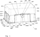
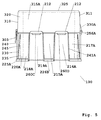
内側ボス側壁を有する内側ボスを有するベースと、内側ボス側壁に配置されるベースリブとの非限定例は、図17および図18に例示される。ベース200に関して例示されるように、ベースは、内側の長い側の表面上に配置されたボス(例えば、ボス272)を含むことができ、ボスは、側面274と、ボス側壁表面275と、近位表面または棚276とを含むことができる。ベース200に関して例示されるように、ベースは、内側の短い側の表面上に配置されたボス(例えば、ボス282)を含むことができ、ボスは、内側ボス側面284と、近位表面286とを含むことができる。ベース200に関して例示されるように、ベースは、ときに、長い側に配置された(例えば、長い側のボス側面に配置された)複数のリブ270(例えば、270A)を含み、その各々は、近位末端縁271(例えば、縁271A)を含む。ベース200に関して例示されるように、ベースは、ときに、短い側に配置された(例えば、短い側のボス側面に配置された)複数のリブ280(例えば、280A)を含み、その各々は、近位末端縁(例えば、縁281A)を含む。リブの近位末端縁(例えば、縁271または縁281)は、ときに、リブの近位末端表面として本明細書において言及される。
A non-limiting example of a base having an inner boss with an inner boss sidewall and a base rib located on the inner boss sidewall is illustrated in FIGS. 17 and 18. As illustrated with respect to the
ベースフットプリントの外部寸法は、ときに、約100ミリメートルから約150ミリメートル(例えば、約110ミリメートルから約135ミリメートル、約110、115、120、125、126、127、128、129、130、135ミリメートル)の長い側の長さを含む。ベースフットプリントの外部寸法は、ときに、約115ミリメートルから約65ミリメートル(約100ミリメートルから約65ミリメートル、約100、95、90、89、88、87、86、85、84、83、82、81、80、75、70、65ミリメートル)の短い側の長さを含む。ベースフットプリントの外部寸法は、ときに、127.76ミリメートル±0.25ミリメートルの長い側の長さと、85.48ミリメートル±0.25ミリメートルの短い側の長さとである。ベースは、ときに、Society for Biomolecular Sciences(SBS)、Society for Biomolecular Screening、および/または米国国家規格協会(ANSI)によって指定された標準フットプリント寸法を有する。ときに、ベース底のフットプリントは、マイクロプレートフットプリントに関して、SBS規格および/またはSBS寸法に従う。 The external dimensions of the base footprint are sometimes about 100 millimeters to about 150 millimeters (eg, about 110 millimeters to about 135 millimeters, about 110, 115, 120, 125, 126, 127, 128, 129, 130, 135 millimeters. ) Including the long side length. The external dimensions of the base footprint are sometimes about 115 millimeters to about 65 millimeters (about 100 millimeters to about 65 millimeters, about 100, 95, 90, 89, 88, 87, 86, 85, 84, 83, 82, 81, 80, 75, 70, 65 mm) short side length. The external dimensions of the base footprint are sometimes 127.76 millimeters ± 0.25 millimeters long side length and 85.48 millimeters ± 0.25 millimeters short side length. The base sometimes has standard footprint dimensions specified by the Society for Biomolecular Sciences (SBS), the Society for Biomolecular Screening, and / or the American National Standards Institute (ANSI). Sometimes the base bottom footprint complies with SBS standards and / or SBS dimensions with respect to the microplate footprint.
(ピペットチップレセプタクルプレート支持特徴)
トレイのためのピペットチップレセプタクルプレート(本明細書においては、「プレート」として言及される)は、ベースの2つ以上壁に配置されている支持特徴と相互作用できるプレート表面上に配置される任意の好適な支持特徴を含み得る。プレートの支持特徴は、2つ以上のプレート縁上に配置され得、多くの場合、プレート遠位表面上に配置される。プレート支持特徴は、一定の実施形態において、リブを含むか、リブからなる。プレートリブは、概して、プレート遠位表面上に配置された接合長さと、接合長さの反対側の非接合長さと、2つの側末端とを含む。接合長さおよび非接合長さは、典型的に、側末端の各々の長さより長く、各側末端は、概して、接合長さの端と、非接合長さの端とに配置される。リブの接合長さと、非接合長さと、各側末端とは、一緒にベースリブ面プロファイルを形成する。プレートリブ面プロファイルは、限定することなく、三角形、四角形、正方形、長方形、台形、ひし形、平行四辺形、または多角形のプロファイルを含む任意の好適なリブプロファイルであることができる。形成されたプレートリブプロファイルは、ときに、平らな側および/または平らな末端を含み、ときに、湾曲した側および/または湾曲した末端を含み、ときに、丸い縁、傾斜した縁、または切断された縁(例えば、丸い遷移、傾斜した遷移、または切断された遷移であり、別の表面との遷移)およびそれらの組み合わせを含む。接合長さが、ときに、リブの主要長さであり、ときに、非接合長さが、リブの主要長さであり、ときに、接合長さと非接合長さとは、等しく、各々が、リブの主要長さである。いくつかの実施形態において、1つ以上または全てのプレートリブの接合長さは、プレートの遠位表面上に配置される(例えば、接合、成形される)。
(Pipette tip receptacle plate support feature)
A pipette tip receptacle plate for a tray (referred to herein as a "plate") is optionally placed on a plate surface that can interact with support features located on more than one wall of the base. Suitable supporting features of The support features of the plate may be located on more than one plate edge, often on the plate distal surface. The plate support features include or consist of ribs in certain embodiments. The plate ribs generally include a bond length disposed on the plate distal surface, a non-bond length opposite the bond length, and two side ends. The joined and unjoined lengths are typically greater than the length of each of the side ends, with each side end generally located at the joined length end and the unjoined length end. The joint length of the ribs, the non-joint length, and each side end together form the base rib face profile. The plate rib face profile can be any suitable rib profile including, but not limited to, triangular, square, square, rectangular, trapezoidal, rhombic, parallelogram, or polygonal profiles. The formed plate rib profile sometimes includes flat sides and / or flat ends, sometimes curved sides and / or curved ends, and sometimes rounded edges, beveled edges, or cuts. Edges (eg, rounded transitions, sloped transitions, or truncated transitions with another surface) and combinations thereof. The bond length is sometimes the major length of the ribs, sometimes the non-bond length is the major length of the ribs, and sometimes the bond length and the non-bond length are equal and each The main length of the rib. In some embodiments, the joint length of one or more or all of the plate ribs is located (eg, joined, shaped) on the distal surface of the plate.
長方形のプレートリブプロファイルに関して、(i)接合長さと非接合長さとは、平行であり、長さが等しく、多くの場合、各々は、リブの主要長さであり、(ii)各側末端は、接合長さと非接合長さとに対して垂直であり、互いに対して平行であり、互いと同じ長さであり、典型的に、接合長さおよび非接合長さより短い。三角形のプレートリブプロファイルに関して、(i)接合長さと非接合長さとは、互いに対して角度付けられ(例えば、約5度から約60度の角度、例えば、約10、15、20、25、30、35、40、45、50、55、60度の角度)、長さは、等しくなく、非接合長さは、多くの場合、リブの主要長さであり、(ii)縁末端の一方は、多くの場合、接合長さに対して垂直または実質的に垂直であり、多くの場合、接合長さおよび非接合長さより短い長さを有し、縁末端のうちの他方は、多くの場合、点である。一定の四角形のプレートリブプロファイルに関して、(i)接合長さと非接合長さとは、ときに、互いに対して角度付けられ(例えば、約5度から約60度の角度、例えば、約5、10、15、20、25、30、35、40、45、50、55、60度の角度)、長さは、等しくなく、非接合長さは、多くの場合、リブの主要長さであり、(ii)側末端の一方は、多くの場合、接合長さに対して垂直または実質的に垂直であり、多くの場合、接合長さおよび非接合長さより短い長さを有し、側末端のうちの他方は、一方より短い。いくつかの四角形のプレートリブプロファイルに関して、(i)接合長さと非接合長さとは、ときに、互いに対して平行または実質的に平行であり、長さは、等しいか、実質的に等しく、非接合長さおよび接合長さは、典型的に、リブの主要長さ(単数または複数)であり、(ii)側末端の一方または両方は、多くの場合、接合長さに対して角度付けられる(例えば、約5度から約60度の角度、例えば、約5、10、15、20、25、30、35、40、45、50、55、60度の角度)。 For a rectangular plate rib profile, (i) the bonded and unbonded lengths are parallel and equal in length, often each is the major length of the rib, and (ii) each side end is , Perpendicular to the bond length and the non-bond length, parallel to each other, of the same length as each other, typically shorter than the bond length and the non-bond length. For triangular plate rib profiles, (i) the bond length and the non-bond length are angled with respect to each other (eg, an angle of about 5 degrees to about 60 degrees, eg, about 10, 15, 20, 25, 30). , 35, 40, 45, 50, 55, 60 degrees), the lengths are not equal and the unbonded length is often the major length of the rib, and (ii) one of the edge ends , Often perpendicular or substantially perpendicular to the bond length, often having a length less than the bond length and the non-bond length, the other of the edge ends often being , Point. For a given square plate rib profile, (i) the bonded length and the unbonded length are sometimes angled relative to each other (eg, an angle of about 5 degrees to about 60 degrees, eg, about 5,10, 15, 20, 25, 30, 35, 40, 45, 50, 55, 60 degrees), the lengths are not equal, and the unbonded length is often the major length of the rib, ( ii) One of the side ends is often perpendicular or substantially perpendicular to the junction length and often has a length less than the junction length and the non-junction length, The other of is shorter than the other. For some square plate rib profiles, (i) the joint length and the non-joint length are sometimes parallel or substantially parallel to each other and the lengths are equal or substantially equal and The bond length and bond length are typically the major length (s) of the ribs, and (ii) one or both side ends are often angled with respect to the bond length. (For example, an angle of about 5 degrees to about 60 degrees, for example, an angle of about 5, 10, 15, 20, 25, 30, 35, 40, 45, 50, 55, 60 degrees).
プレートは、多くの場合、4つの側を有し、多くの場合、長方形であり、2つの対向する短い側と、2つの対向する長い側とを有する。1つ以上または全てのプレートリブの接合長さは、ときに、一方の短い側から他方の対向する短い側への方向に配置され(即ち、長手方向に配置されたリブまたは長手方向リブ)、かつ/または、ときに、一方の長い側から対向する他方の長い側への方向に配置される(即ち、短手方向に配置されたリブまたは短手方向リブ)。1つ以上または全てのプレートリブの接合長さは、ときに、短い側または長い側に対して垂直または実質的に垂直な方向に配置される。いくつかの実施形態において、プレートリブの接合長さは、壁に配置された1つ以上または全ての他のプレートリブの接合長さに対して平行または実質的に平行である。長手方向プレートリブがプレート上に配置されている実施形態において、長手方向プレートリブの接合長さは、プレート上に配置されている1つ以上または全ての他の長手方向プレートリブの接合長さに対して平行または実質的に平行である。短手方向プレートリブがプレート上に配置されている実施形態において、短手方向プレートリブの接合長さは、プレート上に配置されている1つ以上または全ての他の短手方向プレートリブの接合長さに対して平行または実質的に平行である。 The plate often has four sides, often rectangular, and has two opposing short sides and two opposing long sides. The joint length of one or more or all of the plate ribs is sometimes arranged in a direction from one short side to the other opposite short side (ie, longitudinally arranged ribs or longitudinal ribs), And / or sometimes are arranged in a direction from one long side to the other opposite long side (i.e. ribs arranged in the transverse direction or transverse ribs). The joint lengths of one or more or all of the plate ribs are sometimes arranged in a direction that is perpendicular or substantially perpendicular to the short or long sides. In some embodiments, the joint length of the plate ribs is parallel or substantially parallel to the joint length of one or more or all other plate ribs disposed on the wall. In an embodiment in which the longitudinal plate ribs are arranged on the plate, the joint length of the longitudinal plate ribs is equal to the joint length of one or more or all other longitudinal plate ribs arranged on the plate. Parallel to or substantially parallel to. In embodiments where the latitudinal plate ribs are located on the plate, the joining length of the latitudinal plate ribs is such that one or more or all other latitudinal plate ribs located on the plate are joined. It is parallel or substantially parallel to the length.
プレートリブは、等しく間隔を置かれ得(例えば、均一分布)、ときに、2つのプレートリブ間の距離は、他の2つのプレートリブ間の距離と異なる(例えば、不規則分布)。プレート上に存在するとき、短手方向プレートリブは、等しく間隔を置かれ得(例えば、均一分布)、ときに、2つの短手方向プレートリブ間の距離は、他の2つの短手方向プレートリブ間の距離と異なる(例えば、不規則分布)。プレート上に存在するとき、長手方向プレートリブは、等しく間隔を置かれ得(例えば、均一分布)、ときに、2つの長手方向プレートリブ間の距離は、他の2つの長手方向プレートリブ間の距離と異なる(例えば、不規則分布)。以後言及されるように、リブの間隔は、ときに、リブ区分幅によって決定される。 The plate ribs may be evenly spaced (eg, uniform distribution), and sometimes the distance between two plate ribs is different than the distance between two other plate ribs (eg, an irregular distribution). When present on a plate, the latitudinal plate ribs may be evenly spaced (eg, evenly distributed), and sometimes the distance between two latitudinal plate ribs is the other two latitudinal plate. Different from the distance between ribs (eg, irregular distribution). When present on the plate, the longitudinal plate ribs may be equally spaced (eg, evenly distributed), and sometimes the distance between two longitudinal plate ribs is between the other two longitudinal plate ribs. Different from distance (eg, irregular distribution). As mentioned below, rib spacing is sometimes determined by the rib section width.
プレートリブは、1つ以上の露出した縁を有することができる。プレートリブの露出した縁は、(i)ときに、リブの非接合長さに沿った縁(即ち、プレートリブの遠位縁)であり、(ii)ときに、プレートリブの側末端に沿った縁(即ち、プレートリブの側縁)である。プレートリブの露出した縁は、限定することなく、三角形、四角形、正方形、長方形、台形、ひし形、平行四辺形、または多角形の縁プロファイルを含む任意の好適な縁プロファイルを有することができる。縁プロファイルは、ときに、平らな側および/または平らな末端を含み、ときに、湾曲した側および/または湾曲した末端を含み、ときに、丸い縁、傾斜した縁、または切断された縁(例えば、丸い遷移、傾斜した遷移、または切断された遷移であり、別の表面との遷移)およびそれらの組み合わせを含む。プレートリブに関する縁プロファイルは、ときに、互いに対して平行である側を含み、縁に沿ったリブの厚みは、均一または実質的に均一である。プレートリブに関する縁プロファイルは、ときに、互いに対して平行でない側を含み、縁に沿ったリブの厚みは、不連続であり均一でないか、または実質的に均一でない。不連続な厚みを有する縁プロファイルを有するプレートリブ縁の片側または両側は、ときに、縁の一方の側から縁の他方の側まで先細りし、縁プロファイルの1つ以上の側は、ときに、先細り角度またはドラフト角度(例えば、約0.5度から約2度の角度)によって独立して画定される。例えば、プレートリブの非接合長さに沿ったリブの厚みは、均一でなく、(i)厚みは、1つの側末端から対向する側末端まで先細りするか、(ii)厚みは、1つの側末端から非接合長さの縁の中央に向かって広がり、そして、非接合長さの縁の中央から対向する側末端まで先細りするか、(iii)厚みは、プレート遠位表面における接合長さから非接合長さの縁まで先細りするか、(iv)厚みは、非接合長さの縁から遠位プレート表面における接合長さまで先細りするか、または(i)、(ii)、(iii)および(iv)のうちの2つ以上である。非限定的実施例において、プレート400に関して図29に例示されるように、短手方向プレートリブ430は、側縁432と遠位縁433との連結部において切断部を含む。非限定的実施例において、プレート400に関して図25に例示されるように、長手方向プレートリブ434は、側縁436と遠位縁437との連結部において切断部を含む。
The plate ribs can have one or more exposed edges. The exposed edge of the plate rib is, at (i), the edge along the unbonded length of the rib (ie, the distal edge of the plate rib), and (ii) at the side end of the plate rib. Edge (that is, the side edge of the plate rib). The exposed edges of the plate ribs can have any suitable edge profile including, without limitation, triangular, square, square, rectangular, trapezoidal, rhomboid, parallelogram, or polygonal edge profiles. The edge profile sometimes includes flat sides and / or flat ends, sometimes curved sides and / or curved ends, and sometimes rounded edges, beveled edges, or cut edges ( For example, a rounded transition, a sloped transition, or a broken transition, including transitions with another surface) and combinations thereof. Edge profiles for plate ribs sometimes include sides that are parallel to each other, and the thickness of the ribs along the edge is uniform or substantially uniform. The edge profile for the plate ribs sometimes includes sides that are not parallel to each other and the thickness of the ribs along the edge are discontinuous, non-uniform, or substantially non-uniform. One or both sides of a plate rib edge having an edge profile with a discontinuous thickness sometimes tapers from one side of the edge to the other side of the edge and one or more sides of the edge profile sometimes It is independently defined by a taper or draft angle (eg, an angle of about 0.5 degrees to about 2 degrees). For example, the thickness of the ribs along the non-bonded length of the plate ribs is not uniform and (i) the thickness tapers from one side end to the opposite side end, or (ii) the thickness is one side end. From the end to the center of the non-bonded length edge and taper from the center of the non-bonded length edge to the opposite side end, or (iii) the thickness is from the bond length at the plate distal surface. Taper to the non-bonded length edge, or (iv) the thickness tapers from the non-bonded length edge to the bond length at the distal plate surface, or (i), (ii), (iii) and ( iv) two or more. In a non-limiting example, as illustrated in FIG. 29 with respect to
いくつかの実施形態において、プレートの各プレートリブ遠位縁の代表(例えば、平均または中間)または実際の表面積は、短手方向リブに関して約0.040平方インチから約0.060インチ(例えば、約0.045平方インチから約0.055平方インチ;約0.040平方インチから約0.050平方インチ、約0.041、0.042、0.043、0.044、0.045、0.046、0.047、0.048、0.049、0.050、0.051、0.052、0.053、0.054、0.055、0.056、0.057、0.058、0.059平方インチ)であり、長手方向リブに関して約0.080平方インチから約0.100平方インチ(例えば、約0.085平方インチから約0.095平方インチ;約0.088平方インチから約0.092平方インチ、約0.081、0.082、0.083、0.084、0.085、0.086、0.087、0.088、0.089、0.090、0.091、0.092、0.093、0.094、0.095、0.096、0.097、0.098、0.099平方インチ)である。一定の実施形態において、各短手方向リブの長さは、(存在するとき、)約2.70インチから約2.80(例えば、約2.72インチから約2.78インチ、約2.74インチから約2.76インチ、約2.71、2.72、2.73、2.74、2.75、2.76、2.77、2.78、2.79インチ)であり、各長手方向リブの長さは、(存在するとき、)約4.1インチから約4.2インチ(例えば、約4.12インチから約4.18インチ、約4.14インチから約4.16インチ、約4.11、4.12、4.13、4.14、4.15、4.16、4.17、4.18、4.19インチ)である。均一でない厚みを有するプレートリブに関して、プレートリブは、以下の厚み寸法のうちの1つ以上によって特徴付けられ得る。厚み寸法は、(i)約0.025インチから約0.032インチ、約0.027インチから約0.029インチ、約0.025、0.026、0.027、0.028、0.029、0.030、0.031、または0.032インチの代表的リブ厚み(例えば、平均的リブ厚みまたは中間的リブ厚み)と、(ii)約0.030インチから約0.040インチ、0.032インチから約0.038インチ、約0.033インチから約0.037インチ、約0.034インチから約0.036インチ、または約0.030、0.031、0.032、0.033、0.034、0.035、0.036、0.037、0.038、0.039または0.040インチの最大厚みと、(iii)0.017インチから約0.025インチ、約0.018インチから約0.024インチ、約0.019インチから約0.023インチ、約0.020インチから約0.022インチ、または0.017、0.018、0.019、0.020、0.021、0.022、0.023、0.024または0.25インチの最小厚みとである。 In some embodiments, the representative (eg, average or intermediate) or actual surface area of each plate rib distal edge of the plate is about 0.040 square inches to about 0.060 inches (e.g., about the transverse rib). About 0.045 square inches to about 0.055 square inches; about 0.040 square inches to about 0.050 square inches, about 0.041, 0.042, 0.043, 0.044, 0.045, 0. 0.046, 0.047, 0.048, 0.049, 0.050, 0.051, 0.052, 0.053, 0.054, 0.055, 0.056, 0.057, 0.058 , 0.059 square inches) and about 0.080 square inches to about 0.100 square inches (eg, about 0.085 square inches to about 0.095 square inches; about 0 for the longitudinal ribs). 088 square inches to about 0.092 square inches, about 0.081, 0.082, 0.083, 0.084, 0.085, 0.086, 0.087, 0.088, 0.089, 0. 090, 0.091, 0.092, 0.093, 0.094, 0.095, 0.096, 0.097, 0.098, 0.099 square inches). In certain embodiments, the length of each transverse rib (when present) is about 2.70 inches to about 2.80 (eg, about 2.72 inches to about 2.78 inches, about 2.78 inches). 74 inches to about 2.76 inches, about 2.71, 2.72, 2.73, 2.74, 2.75, 2.76, 2.77, 2.78, 2.79 inches), The length of each longitudinal rib (when present) is about 4.1 inches to about 4.2 inches (eg, about 4.12 inches to about 4.18 inches, about 4.14 inches to about 4.14 inches). 16 inches, about 4.11, 4.12, 4.13, 4.14, 4.15, 4.16, 4.17, 4.18, 4.19 inches). For plate ribs having a non-uniform thickness, the plate ribs can be characterized by one or more of the following thickness dimensions. The thickness dimension is (i) about 0.025 inch to about 0.032 inch, about 0.027 inch to about 0.029 inch, about 0.025, 0.026, 0.027, 0.028, 0.02 inch. A typical rib thickness of 029, 0.030, 0.031, or 0.032 inches (eg, an average rib thickness or an intermediate rib thickness), and (ii) about 0.030 inches to about 0.040 inches. 0.032 inch to about 0.038 inch, about 0.033 inch to about 0.037 inch, about 0.034 inch to about 0.036 inch, or about 0.030, 0.031, 0.032, 0. A maximum thickness of 0.033, 0.034, 0.035, 0.036, 0.037, 0.038, 0.039 or 0.040 inches and (iii) 0.017 inches to about 0.025 inches, About 0 018 inches to about 0.024 inches, about 0.019 inches to about 0.023 inches, about 0.020 inches to about 0.022 inches, or 0.017, 0.018, 0.019, 0.020, With a minimum thickness of 0.021, 0.022, 0.023, 0.024 or 0.25 inches.
一定の実施形態において、プレート上に配置されるプレートリブの一部または全ては、同じ縁プロファイルを有し、ときに、プレート上に配置される2つ以上または全てのプレートリブは、1つ以上の異なる縁プロファイルを有する。プレート上に配置される短手方向プレーの一部または全ては、ときに、同じ縁プロファイルを有し、ときに、プレート上に配置される2つ以上または全ての短手方向プレートは、1つ以上の異なる縁プロファイルを有する。プレート上に配置される長手方向プレーの一部または全ては、ときに、同じ縁プロファイルを有し、ときに、プレート上に配置される2つ以上または全ての長手方向プレートは、1つ以上の異なる縁プロファイルを有する。 In certain embodiments, some or all of the plate ribs disposed on the plate have the same edge profile, and sometimes two or more or all plate ribs disposed on the plate are one or more. With different edge profiles. Some or all of the latitudinal plays placed on the plate sometimes have the same edge profile, and sometimes two or more or all of the latitudinal plates placed on the plate are one. It has the above different edge profiles. Some or all of the longitudinal plays arranged on the plate sometimes have the same edge profile, and sometimes two or more or all longitudinal plates arranged on the plate are one or more. It has different edge profiles.
一定の実施形態におけるプレートは、1つ以上の長手方向リブと、1つ以上の短手方向リブとを含む。いくつかの実施形態において、プレートは、複数の長手方向リブ(即ち、長手方向リブの組)と、複数の短手方向リブ(即ち、短手方向リブの組)とを含む。一定の実施形態において、長手方向プレートリブの各々は、複数のプレートリブ連結部において短手方向プレートリブの組と交差し、短手方向プレートリブの各々は、複数のプレートリブ連結部において長手方向プレートリブの組と交差する。 The plate in certain embodiments includes one or more longitudinal ribs and one or more transverse ribs. In some embodiments, the plate includes a plurality of longitudinal ribs (ie, a set of longitudinal ribs) and a plurality of transverse ribs (ie, a set of transverse ribs). In certain embodiments, each of the longitudinal plate ribs intersects the set of latitudinal plate ribs at the plurality of plate rib connections and each of the latitudinal plate ribs extends in the longitudinal direction at the plurality of plate rib connections. Intersects a set of plate ribs.
一定の実施形態において、プレートは、プレート遠位表面から遠位に延びているプレート側壁を含み、プレート側壁は、多くの場合、プレート遠位表面から垂直または実質的に垂直に延びている。プレート側壁は、多くの場合、外側側壁表面と、内側側壁表面と含む。いくつかの実施形態におけるプレートは、プレート側壁外側表面から延びているフランジを含み、フランジは、多くの場合、プレート内側から離れてプレート側壁外側表面から垂直または実質的に垂直に延びている。フランジは、ときに、(i)多くの場合にプレート周囲を囲む外面フランジ縁と、(ii)多くの場合にプレートの足表面を形成するフランジ遠位表面とを含み、ときに、(iii)プレート側壁外側表面から離れて突起し、外側棚を形成することができるフランジ近位表面を含む。 In certain embodiments, the plate includes a plate sidewall extending distally from the plate distal surface, the plate sidewall often extending vertically or substantially vertically from the plate distal surface. Plate sidewalls often include an outer sidewall surface and an inner sidewall surface. The plate in some embodiments includes a flange extending from the plate sidewall outer surface, the flange often extending vertically or substantially vertically from the plate sidewall outer surface away from the plate inner side. The flange sometimes comprises (i) an outer flange edge, which often surrounds the plate perimeter, and (ii) a flange distal surface, which often forms the foot surface of the plate, and (iii) It includes a flange proximal surface that can project away from the plate sidewall outer surface to form an outer ledge.
いくつかの実施形態において、プレート遠位表面上に配置されたプレートリブの各々の接合長さは、プレートリブが配置されている遠位表面の対向する縁間の長さに等しいか、実質的に等しい。いくつかの実施形態において、プレートリブの少なくとも一部分または全ての各々の一方の側縁または両方の側縁は、プレートの近位表面の周囲から0.05インチ以下の距離であるか、プレートの遠位表面の周囲から0.05インチ以下の距離であり、距離の方向は、プレートの近位表面に対して平行である。一定の実施形態において、プレートリブの少なくとも一部分または全ての各々の一方の側縁または両方の側縁は、プレートの遠位表面の周囲と同一範囲である。一定の実施形態において、プレートは、遠位に延びている側壁を備え、側壁は、外側側壁表面と、内側側壁表面とを含み、プレートリブの少なくとも一部分の各々の一方の側縁または両方の側縁または全ての側縁は、内側側壁表面から0.05インチ以下の距離であり、距離の方向は、プレートの近位表面に対して平行である。いくつかの実施形態において、プレートは、遠位に延びている側壁を備え、側壁は、外側側壁表面と、内側側壁表面とを含みプレートリブの、少なくとも一部分または全ての各々の一方の側縁または両方の側縁は、内側側壁表面に接する。いくつかの実施形態において、(i)プレートリブの一方の側縁または両方の側縁と、(ii)近位表面の周囲、遠位表面の周囲、または内側側壁表面との間の距離は、約0.05、0.045、0.04、0.035、0.03、0.025、0.02、0.015、0.01、0.008、0.006、0.005、0.004、0.002、または0.001インチ以下である。非限定的実施例において、プレート400に関して図29に例示されるように、リブ430の側縁432は、プレート側壁の内側表面417Aに接する。
In some embodiments, the joint length of each of the plate ribs disposed on the plate distal surface is equal to or substantially equal to the length between opposing edges of the distal surface on which the plate ribs are disposed. be equivalent to. In some embodiments, at least a portion or all of the plate ribs each has one or both side edges at a distance of 0.05 inches or less from a perimeter of the proximal surface of the plate, or at a far distance of the plate. A distance of 0.05 inches or less from the perimeter of the surface, the direction of the distance being parallel to the proximal surface of the plate. In certain embodiments, at least some or all of the plate ribs each have one or both side edges coextensive with the periphery of the plate's distal surface. In certain embodiments, the plate comprises a distally extending side wall, the side wall including an outer side wall surface and an inner side wall surface, wherein one or both sides of each of at least a portion of the plate ribs. The edge or all side edges are no more than 0.05 inches from the inner sidewall surface and the direction of the distance is parallel to the proximal surface of the plate. In some embodiments, the plate comprises a distally extending side wall, the side wall including an outer side wall surface and an inner side wall surface, each side edge of at least a portion or all of the plate ribs or Both side edges abut the inner sidewall surface. In some embodiments, the distance between (i) one or both side edges of the plate rib and (ii) the proximal surface, the distal surface, or the inner sidewall surface is: About 0.05, 0.045, 0.04, 0.035, 0.03, 0.025, 0.02, 0.015, 0.01, 0.008, 0.006, 0.005, 0 0.004, 0.002, or 0.001 inches or less. In a non-limiting example, the side edges 432 of the
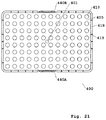
プレートにおけるボアの配列は、複数の配列の列と、複数の配列の行とを含むことができる。列の配列における各列は、ときに、長い側からプレートの対向する長い側へ延び、行の配列における各行は、ときに、短い側から対向するプレートの短い側へ延びる。各配列の列は、ボアの配列におけるボアの一部cを含み、各配列の行は、ボアの配列におけるボアの一部rを含む。ボアの配列は、任意の好適な数の配列の列と、任意の好適な数の配列の行とを含むことができる。例えば、図21に示されるプレートは、12個の配列の列と、8個の配列の行とを含む。いくつかの実施形態において、各配列の列は、c個のボアを備え、プレートは、c−1個の長手方向プレートリブを備え、各配列の列の各ボアは、1つまたは2つの長手方向プレートリブに隣接する。いくつかの実施形態において、プレートは、短手方向プレートリブの各々の上にc−1個のプレートリブ連結部を備え、各配列の列の各ボアは、1つまたは2つの短手方向リブに隣接する。一定の実施形態において、各配列の行は、r個のボアを備え、プレートは、r−1個の短手方向プレートリブを備え、各配列の行における各ボアは、1つまたは2つの短手方向プレートリブに隣接する。いくつかの実施形態において、プレートは、長手方向プレートリブの各々の上にr−1プレートリブ連結部を備え、各配列の行における各ボアは、1つまたは2つの長手方向リブに隣接する。各配列の列における各ボアまたは各配列の行における各ボアは、概して、配列の列または配列の行が最初または最後の配列の列または配列の行である(即ち、配列の列または配列の行がプレート周囲の近くに位置する)とき、1つの短手方向リブに隣接する。各配列の列における各ボアまたは各配列の行における各ボアは、概して、配列の列または配列の行が内部配列の列または内部配列の行でありかつ最初または最後の配列の列または配列の行ではない(即ち、配列の列または配列の行がプレート周囲の近くに位置しない)とき、2つの短手方向リブに隣接する。 The array of bores in the plate can include multiple arrays of columns and multiple arrays of rows. Each column in the array of columns sometimes extends from the long side to the opposite long side of the plate, and each row in the array of rows sometimes extends from the short side to the short side of the opposing plate. The columns of each array include a portion c of the bore in the array of bores, and the rows of each array include a portion r of the bore in the array of bores. The array of bores can include any suitable number of columns of arrays and any suitable number of arrays of rows. For example, the plate shown in Figure 21 includes 12 arrays of columns and 8 arrays of rows. In some embodiments, each array row comprises c bores and the plate comprises c-1 longitudinal plate ribs, each bore of each array row having one or two longitudinal plates. Adjacent to the direction plate ribs. In some embodiments, the plate comprises c-1 plate rib connections on each of the latitudinal plate ribs, each bore of each array row having one or two latitudinal ribs. Adjacent to. In certain embodiments, each array row comprises r bores, the plate comprises r-1 transverse plate ribs, and each bore in each array row has one or two short bores. Adjacent to the hand plate ribs. In some embodiments, the plate comprises an r-1 plate rib connection on each of the longitudinal plate ribs, with each bore in each array row adjoining one or two longitudinal ribs. Each bore in each array column or each array row is generally that column or array row is the first or last array column or array row (ie, array column or array row). Is located near the perimeter of the plate), adjoins one transverse rib. Each bore in each array column or each array row is generally a column or array row of an array that is an internal array column or internal array row and the first or last array column or array row. If not (ie, the columns or rows of the array are not located near the plate perimeter), then adjoin the two transverse ribs.
プレートリブの高さは、プレートリブの遠位縁に沿った任意の地点で測定され、プレート遠位表面からリブの遠位縁上のその地点まで垂直に延びている距離として測定される。例えば、2つのリブの高さの寸法であるh1およびh2は、図25に示される。プレートが1つ以上の連結部を含み、連結部において1つ以上の短手方向リブと1つ以上の長手方向リブとが交差する実施形態において、連結部を有する各リブは、(i)リブにおける2つの連結部間のリブ区分を有するか、または(ii)隣接するリブ連結部とリブの縁との間のリブ区分を有する。リブの任意のリブ区分の幅(即ち、リブ区分幅)は、(i)リブの側縁から隣接するリブ連結部までの間、または(ii)2つの隣接するリブ連結部間のリブの遠位縁に対して平行である距離として測定されることができる。例えば、側縁から隣接するリブ連結部までの間のリブ区分幅は、w1として図26に示され、2つの隣接するリブ連結部間のリブ区分幅は、w2として図26に示される。リブの高さ(例えば、h1およびh2)と、リブ区分幅(例えば、w1およびw2)とを決定することは、以下で図25と、図26と、図29とを参照してより詳細に説明される。 The height of a plate rib is measured at any point along the distal edge of the plate rib and is measured as the distance that extends vertically from the plate distal surface to that point on the distal edge of the rib. For example, the height dimensions h1 and h2 of the two ribs are shown in FIG. In an embodiment in which the plate includes one or more joints, where one or more transverse ribs and one or more longitudinal ribs intersect at the joints, each rib having a joint comprises (i) a rib. Or (ii) with a rib section between adjacent rib joints and rib edges. The width of any rib section of the rib (ie, rib section width) is either (i) from the side edge of the rib to an adjacent rib connection, or (ii) the distance of the rib between two adjacent rib connections. It can be measured as the distance that is parallel to the edge. For example, the rib section width from the side edge to the adjacent rib connection section is shown as w1 in FIG. 26, and the rib section width between two adjacent rib connection sections is shown as w2 in FIG. Determining rib heights (eg, h1 and h2) and rib segment widths (eg, w1 and w2) will be described in more detail below with reference to FIGS. 25, 26, and 29. Explained.
いくつかの実施形態において、プレート上に配置された1つ以上または全てのリブ、1つ以上または全ての短手方向リブ、および/または1つ以上または全ての長手方向リブは、均一でない高さを有する。代表的高さ(例えば、平均的高さまたは中間的高さ)は、リブの遠位縁に沿って規則的に分散される高さ寸法を平均化させることによって均一でない高さを有するリブに関して決定されることができる。一定の実施形態において、プレート上に配置された、1つ以上または全てのリブ、1つ以上または全ての短手方向リブ、および/または1つ以上または全ての長手方向リブは、均一な高さを有する。いくつかの実施形態において、プレート上に配置されたリブの一部または全ては、同じ均一な高さを有し、ときに、プレート上に配置された2つ以上または全てのプレートリブは、1つ以上の異なる均一な高さを有する。いくつかの実施形態において、プレート上に配置された長手方向プレートリブの一部または全ては、同じ均一な高さを有し、ときに、プレート上に配置された2つ以上または全ての長手方向プレートリブは、1つ以上の異なる均一な高さを有する。一定の実施形態において、プレート上に配置された短手方向プレートリブの一部または全ては、同じ均一な高さを有し、ときに、プレート上に配置された2つ以上または全ての短手方向プレートリブは、1つ以上の異なる均一な高さを有する。いくつかの実施形態において、プレートのリブの各々の高さは、均一であり、プレートのリブ全てに関しても同じであり、約0.2インチから約0.6インチ、約0.25インチから約0.55インチ、約0.3インチから約0.5インチ、約0.35インチから約0.45インチ、約0.37インチから約0.43インチ、または約0.30、0.31、0.32、0.33、0.34、0.35、0.36、0.37、0.38、0.39、0.40、0.41、0.42、0.43、0.44、0.45、0.46、0.47、0.48、0.49または0.50インチである。 In some embodiments, one or more or all ribs, one or more or all transverse ribs, and / or one or more or all longitudinal ribs disposed on the plate have non-uniform heights. Have. A typical height (eg, average height or intermediate height) is for a rib having a non-uniform height by averaging the height dimensions that are regularly distributed along the distal edge of the rib. Can be determined. In certain embodiments, one or more or all ribs, one or more or all transverse ribs, and / or one or more or all longitudinal ribs disposed on the plate have a uniform height. Have. In some embodiments, some or all of the ribs disposed on the plate have the same uniform height, and sometimes two or more or all plate ribs disposed on the plate are 1 It has three or more different uniform heights. In some embodiments, some or all of the longitudinal plate ribs located on the plate have the same uniform height, and sometimes more than one or all longitudinal plates located on the plate. The plate ribs have one or more different uniform heights. In certain embodiments, some or all of the latitudinal plate ribs disposed on the plate have the same uniform height, and sometimes two or more or all lateral sides disposed on the plate. The directional plate ribs have one or more different uniform heights. In some embodiments, the height of each of the ribs on the plate is uniform and the same for all ribs on the plate, from about 0.2 inches to about 0.6 inches, from about 0.25 inches to about 0.25 inches. 0.55 inch, about 0.3 inch to about 0.5 inch, about 0.35 inch to about 0.45 inch, about 0.37 inch to about 0.43 inch, or about 0.30, 0.31 , 0.32, 0.33, 0.34, 0.35, 0.36, 0.37, 0.38, 0.39, 0.40, 0.41, 0.42, 0.43, 0 .44, 0.45, 0.46, 0.47, 0.48, 0.49 or 0.50 inch.
いくつかの実施形態において、プレート上に配置された、1つ以上または全てのリブ、1つ以上または全ての短手方向リブ、および/または1つ以上または全ての長手方向リブは、均一でないリブ区分幅を有する。代表的リブ区分幅(例えば、平均的リブ区分幅または中間的リブ区分幅)は、リブに関してリブ区分幅測定値を平均化させることによって均一でないリブ区分幅を有するリブに関して決定されることができる。一定の実施形態において、プレート上に配置された、1つ以上または全てのリブ、1つ以上または全ての短手方向リブ、および/または1つ以上または全ての長手方向リブは、均一なリブ区分幅を有する。いくつかの実施形態において、プレート上に配置されたリブに一部または全ては、同じ均一なリブ区分幅を有し、ときに、プレート上に配置された2つ以上または全てのプレートリブは、1つ以上の異なる均一なリブ区分幅を有する。いくつかの実施形態において、プレート上に配置された長手方向プレートリブの一部または全ては、同じ均一なリブ区分幅を有し、ときに、プレート上に配置された2つ以上または全ての長手方向プレートリブは、1つ以上の異なる均一なリブ区分幅を有する。一定の実施形態において、プレート上に配置された短手方向プレートリブの一部または全ては、同じ均一なリブ区分幅を有し、ときに、プレート上に配置された2つ以上または全ての短手方向プレートリブは、1つ以上の異なる均一なリブ区分幅を有する。いくつかの実施形態において、プレートのリブの各々のリブ区分幅は、均一であり、プレートのリブ全てに関しても同じであり、約0.25インチから約0.40インチ、約0.27インチから約0.37インチ、約0.30インチから約0.35インチ、約0.31インチから約0.33インチ、または約0.28、0.29、0.30、0.31、0.32、0.33、0.34、0.35、または0.36インチである。 In some embodiments, the one or more or all ribs, one or more or all transverse ribs, and / or one or more or all longitudinal ribs disposed on the plate are non-uniform ribs. It has a section width. A representative rib section width (eg, average rib section width or intermediate rib section width) can be determined for ribs having non-uniform rib section widths by averaging the rib section width measurements for the ribs. . In certain embodiments, one or more or all ribs, one or more or all transverse ribs, and / or one or more or all longitudinal ribs disposed on the plate have uniform rib divisions. Has a width. In some embodiments, some or all of the ribs disposed on the plate have the same uniform rib section width, and sometimes two or more or all plate ribs disposed on the plate have It has one or more different uniform rib section widths. In some embodiments, some or all of the longitudinal plate ribs located on the plate have the same uniform rib section width, and sometimes two or more or all longitudinal plates located on the plate. The directional plate ribs have one or more different uniform rib section widths. In certain embodiments, some or all of the latitudinal plate ribs disposed on the plate have the same uniform rib section width, and sometimes more than one or all of the short side plate ribs disposed on the plate. The manual plate ribs have one or more different uniform rib section widths. In some embodiments, the rib section width of each of the plate ribs is uniform and the same for all of the plate ribs, from about 0.25 inches to about 0.40 inches, from about 0.27 inches. About 0.37 inch, about 0.30 inch to about 0.35 inch, about 0.31 inch to about 0.33 inch, or about 0.28, 0.29, 0.30, 0.31, 0.3. 32, 0.33, 0.34, 0.35, or 0.36 inches.
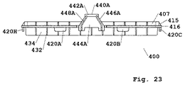
非限定的実施例において、プレートは、図19から図27に示されるプレート実施形態400において例示されるように、近位表面405と、側壁外側表面407と、遠位表面409と、ボアの配列におけるボア410と、ボア側壁縁412とを含む。プレートは、ときに、例えば、プレート400に関して示されるように、以下の特徴のうちの1つ以上を有するサポート構造を含む。特徴は、側縁432(例えば、432A、432B、432C)および遠位縁433(例えば、433A、433B)を有する短手方向リブ430(例えば、430A、430B)と、側縁436(例えば、436A、436B、436C)および遠位縁437(例えば、437A、437B)を有する長手方向リブ434(例えば、434A、434B)と、短手方向リブおよび長手方向リブの間の連結部435と、特定の短手方向リブおよび特定の長手方向リブの間にありかつ末端438を有する強化された連結部439とである。そのような実施例において、(i)図25に例示されるように、リブの高さは、プレート遠位表面409とリブ遠位縁437との間の距離h1またはh2であり(この実施例において、h1およびh2は、プレートリブ434に関して等しい)、(ii)長手方向リブ424Bに関して図27に例示されるように、長手方向リブの長さは、側末端436Bから側末端436Cまでの遠位縁437Bに沿った距離であり、(iii)短手方向リブ430Bに関して図27に例示されるように、短手方向リブの長さは、側末端432Bから側末端432Cまでの遠位縁433Bに沿った距離であり、(iv)図26に例示されるように、リブ区分幅は、(1)(図29に示される)側壁417Aから隣接するリブ433の最も近い側までの間の距離w1または(2)リブ433の側から隣接するリブ433の最も近い側まで間の距離w2である。
In a non-limiting example, the plate has an array of
(ベース支持部材とプレート支持部材との間の相互作用)
プレートがベースに接続されている実施例において、ベース支持部材の少なくとも一部の各々の少なくとも一部分は、プレート支持部材の一部分と接触している。一定の実施形態において、ベースリブの少なくとも一部の各々の近位末端の少なくとも一部分は、プレートリブの一部分と接触している。いくつかの実施形態において、ベースの壁に配置されているベースリブの各々の近位末端の少なくとも一部分は、プレートリブの一部分と接触している。一定の実施形態において、ベースの内側側壁に配置されているベースリブの各々の近位末端全体は、プレートリブの一部分と接触している。論理によって限定されることなく、プレートリブの一部分と接触している各ベースリブの近位末端は、プレートリブおよびプレートに支持を提供する。論理によって限定されることなく、プレートリブの遠位縁の一部分と接触している各ベースリブの近位末端間の相互作用によって提供される集合的支持は、そのような相互作用を提供しないプレート/ベース組み合わせに対して、プレート剛性を高め、負荷下のプレート変形を低減させる。
(Interaction between the base support member and the plate support member)
In the embodiment where the plate is connected to the base, at least a portion of each of the at least a portion of the base support member is in contact with a portion of the plate support member. In certain embodiments, at least a portion of each proximal end of at least a portion of the base rib is in contact with a portion of the plate rib. In some embodiments, at least a portion of the proximal end of each of the base ribs located in the wall of the base is in contact with a portion of the plate ribs. In certain embodiments, the entire proximal end of each of the base ribs located on the inner sidewall of the base is in contact with a portion of the plate ribs. Without being limited by logic, the proximal end of each base rib in contact with a portion of the plate rib provides support for the plate rib and plate. Without being limited by logic, the collective support provided by the interaction between the proximal ends of each base rib in contact with a portion of the distal edge of the plate ribs provides a plate / plate that does not provide such interaction. Increases plate rigidity and reduces plate deformation under load compared to base combinations.
プレートリブの遠位縁の一部分と相互作用するベースリブの近位末端は、概して、ベースリブの近位末端に位置する縁(即ち、縁表面)であり、ときに、ベースリブの縁の一部分または縁全体は、プレートリブ遠位縁の一部分の一部分と接触している。一定の実施形態において、ベースリブの近位末端縁の表面積の約5パーセントから約100パーセントは、プレートリブ遠位末端縁の一部分と接触する(例えば、ベースリブの近位末端縁の表面積の約10パーセントから約100パーセント、約20パーセントから約100パーセント、約30パーセントから約100パーセント、約40パーセントから約100パーセント、約50パーセントから約100パーセント、約60パーセントから約100パーセント、約70パーセントから約100パーセント、約80から約100パーセント、または約90パーセントから約100パーセントが、プレートリブ遠位末端縁の一部分と接触する)。いくつかの実施形態において、プレートリブの遠位縁の一部分と接触している近位縁において、リブが配置されているベース内側側壁からベースの中心に向かっているリブ縁までのベースリブの近位末端縁の長さは、ときに、約0.03インチから約0.2インチ(例えば、約0.04インチから約0.15インチ;約0.05インチから約0.12インチ;約0.06インチから約0.09インチ、約0.03、0.04、0.05、0.06、0.07、0.08、0.09、0.10、0.11、0.12、0.13、0.14、0.15、0.16、0.17、0.18、0.19、0.20インチ)である。 The proximal end of the base rib that interacts with a portion of the distal edge of the plate rib is generally the edge (i.e., edge surface) located at the proximal end of the base rib, and sometimes, a portion or the entire edge of the base rib. Contact a portion of a portion of the plate rib distal edge. In certain embodiments, about 5 percent to about 100 percent of the surface area of the proximal end edge of the base rib contacts a portion of the plate rib distal end edge (eg, about 10 percent of the surface area of the proximal end edge of the base rib). From about 100 percent, about 20 percent to about 100 percent, about 30 percent to about 100 percent, about 40 percent to about 100 percent, about 50 percent to about 100 percent, about 60 percent to about 100 percent, about 70 percent to about. 100 percent, about 80 to about 100 percent, or about 90 percent to about 100 percent contact a portion of the plate rib distal end edge). In some embodiments, at the proximal edge in contact with a portion of the distal edge of the plate rib, the proximal of the base rib from the base inner sidewall where the rib is located to the rib edge toward the center of the base. The length of the distal edge is sometimes about 0.03 inches to about 0.2 inches (eg, about 0.04 inches to about 0.15 inches; about 0.05 inches to about 0.12 inches; about 0). 0.06 inch to about 0.09 inch, about 0.03, 0.04, 0.05, 0.06, 0.07, 0.08, 0.09, 0.10, 0.11, 0.12 , 0.13, 0.14, 0.15, 0.16, 0.17, 0.18, 0.19, 0.20 inch).
非限定的実施例において、ベースリブ270の近位末端縁271の縁全体は、ベース200およびプレート400に関して図29に例示されるように、プレートリブ430の側縁432と遠位縁433との間の切断部に配置されている空間を除いて、プレートリブ430の遠位縁433と接触している。非限定的実施例において、各ベースリブ270の近位末端271は、図15に例示されるように、短手方向プレートリブの一部において、連結部155で、各短手方向プレートリブ430の遠位末端縁433に接触する。図15に例示されるように、例えば、近位縁271における各ベースリブ270の厚みtbは、各プレートリブ430の遠位末端縁433における厚みtpより大きい。非限定的実施例において、図16に例示されるように、各ベースリブ280の近位末端281は、長手方向プレートリブの一部において、連結部150で、各長手方向プレートリブ434の遠位末端縁437に接触する。図16に例示されるように、例えば、近位縁281における各ベースリブ280の厚みtbは、遠位末端縁437における各プレートリブ434の厚みtpより大きい。
In a non-limiting example, the entire edge of the
いくつかの実施形態において、ベースは、2つの短い側と、2つの長い側とを備え、ベースは、2つの短い側の各々の内側表面上に配置されている複数の軸方向に配置されたベースリブを備え、2つの短い側の各々に配置されたベースリブの各々の近位末端の表面は、長手方向プレートリブの遠位縁の一部分に接触し、ベースは、2つの長い側の各々の内側表面上に配置されている複数の軸方向に配置されたベースリブを備え、2つの長い側各々に配置されたベースリブの各々の近位末端の表面は、短手方向プレートリブの遠位縁の一部分に接触する。一定の実施形態において、プレートリブの遠位縁の一部分と接触しているベースリブの各々の近位末端の表面は、プレートリブ遠位縁の周辺部分に接触する。いくつかの実施形態において、プレートリブの一部は、ベースリブと接触している。非限定的実施例において、図15に例示されるように、全ての短手方向プレートリブ430のうちの一部は、全てのベースリブ270と接触しており、全ての長手方向リブ434のうちの一部は、全てのベースリブ280と接触している。
In some embodiments, the base comprises two short sides and two long sides and the base is arranged in a plurality of axially disposed on the inner surface of each of the two short sides. A surface of the proximal end of each of the base ribs comprising a base rib disposed on each of the two short sides contacts a portion of the distal edge of the longitudinal plate ribs, and the base is on the inside of each of the two long sides. A plurality of axially-disposed base ribs disposed on the surface, each proximal end surface of each of the two longer sides of the base rib having a portion of a distal edge of the latitudinal plate rib. To contact. In certain embodiments, the surface of the proximal end of each of the base ribs that contacts a portion of the distal edge of the plate rib contacts the peripheral portion of the plate rib distal edge. In some embodiments, a portion of the plate rib is in contact with the base rib. In a non-limiting example, as illustrated in FIG. 15, some of all the
一定の実施形態において、ベースの全てのベースリブの近位末端縁の全表面積(即ち、集合的表面積)は、約0.066平方インチから約0.110平方インチ(例えば、約0.075平方インチから約0.10平方インチ、約0.080平方インチから約0.095平方インチ、約0.085平方インチから約0.090平方インチ、約0.068、0.070、0.072、0.074、0.076、0.078、0.080、0.080、0.082、0.084、0.086、0.088、0.090、0.092、0.094、0.096、0.098、0.10、0.12、0.14、0.16、0.18、0.11平方インチ)である。いくつかの実施形態において、プレートの全てのプレートリブの遠位末端縁の全表面積(即ち、集合的表面積)は、約1.00平方インチから約1.30平方インチ(例えば、約1.05平方インチから約1.25平方インチ、約1.1平方インチから約1.2平方インチ、約1.00、1.02、1.04、1.06、1.08、1.10、1.12、1.14、1.16、1.18、1.20、1.22、1.24、1.26、1.28、1.30平方インチ)である。一定の実施形態において、ベースの全てのベースリブの近位末端縁と接触しているプレートリブ遠位縁の部分の全表面積(即ち、集合的表面積)は、約0.001平方インチから約0.003平方インチ(例えば、約0.0015平方インチから約0.0025平方インチ、約0.0010、0.0012、0.0014、0.0016、0.0018、0.0020、0.0022、0.0024、0.0026、0.0028、0.0030平方インチ)である。いくつかの実施形態において、(i)ベースのベースリブの全ての近位末端縁と接触しているプレートリブ遠位縁の部分の全表面積(即ち、集合的表面積)の(ii)プレートのプレートリブの全ての遠位末端縁の全表面積(即ち、集合的表面積)に対するパーセントは、約0.001パーセントから約0.003パーセント(例えば、約0.0015パーセントから約0.0025パーセント、約0.0010、0.0012、0.0014、0.0016、0.0018、0.0020、0.0022、0.0024、0.0026、0.0028、0.0030パーセント)である。 In certain embodiments, the total surface area (ie, collective surface area) of the proximal end edges of all base ribs of the base is from about 0.066 square inches to about 0.110 square inches (eg, about 0.075 square inches). To about 0.10 square inches, about 0.080 square inches to about 0.095 square inches, about 0.085 square inches to about 0.090 square inches, about 0.068, 0.070, 0.072, 0. 0.074, 0.076, 0.078, 0.080, 0.080, 0.082, 0.084, 0.086, 0.088, 0.090, 0.092, 0.094, 0.096 , 0.098, 0.10, 0.12, 0.14, 0.16, 0.18, 0.11 square inch). In some embodiments, the total surface area (ie, collective surface area) of the distal end edges of all plate ribs of the plate is from about 1.00 square inches to about 1.30 square inches (eg, about 1.05 square inches). Square inches to about 1.25 square inches, about 1.1 square inches to about 1.2 square inches, about 1.00, 1.02, 1.04, 1.06, 1.08, 1.10, 1. .12, 1.14, 1.16, 1.18, 1.20, 1.22, 1.24, 1.26, 1.28, 1.30 square inches). In certain embodiments, the total surface area (ie, the collective surface area) of the portion of the plate rib distal edge that is in contact with the proximal end edges of all base ribs of the base is from about 0.001 square inches to about 0. 003 square inches (eg, about 0.0015 square inches to about 0.0025 square inches, about 0.0010, 0.0012, 0.0014, 0.0016, 0.0018, 0.0020, 0.0022, 0). .0024, 0.0026, 0.0028, 0.0030 square inch). In some embodiments, (ii) the plate ribs of the plate of (ii) the total surface area (ie, collective surface area) of the portion of the plate rib distal edge that is in contact with all the proximal end edges of the base ribs of the base. Relative to the total surface area (i.e., collective surface area) of all distal end edges of about 0.001 percent to about 0.003 percent (eg, about 0.0015 percent to about 0.0025 percent, about 0. 0010, 0.0012, 0.0014, 0.0016, 0.0018, 0.0020, 0.0022, 0.0024, 0.0026, 0.0028, 0.0030 percent).
一定の実施形態において、プレートリブの遠位縁の一部分と接触しているベースリブの各々の近位末端におけるリブ厚みは、ベースリブの近位末端と接触しているプレートリブの遠位縁におけるリブ厚みに対して大きいか、小さいか、または等しい。いくつかの実施形態において、プレートリブの遠位縁の一部分と接触しているベースリブの各々の近位末端におけるリブ厚みは、ベースリブの近位末端と接触しているプレートリブの遠位縁におけるリブ厚みより大きい。一定の実施形態において、プレートリブの遠位縁の一部分と接触しているベースリブの各々の近位末端におけるリブ厚みは、約0.020インチから約0.030インチ(例えば、約0.022インチから約0.028インチ、約0.024インチから約0.026インチ、約0.021、0.022、0.023、0.024、0.025、0.026、0.027、0.028、0.029インチ)である。いくつかの実施形態において、ベースリブの近位末端と接触しているプレートリブの遠位縁におけるリブ厚みは、約0.017インチから約0.025インチ、約0.018インチから約0.024インチ、約0.019インチから約0.023インチ、約0.020インチから約0.022インチ、または約0.017、0.018、0.019、0.020、0.021、0.022、0.023、0.024、または0.25インチである。 In certain embodiments, the rib thickness at the proximal end of each of the base ribs in contact with a portion of the distal edge of the plate rib is the rib thickness at the distal edge of the plate rib in contact with the proximal end of the base rib. Greater than, less than, or equal to. In some embodiments, the rib thickness at the proximal end of each of the base ribs that contacts a portion of the distal edge of the plate rib is the rib at the distal edge of the plate rib that contacts the proximal end of the base rib. Greater than thickness. In certain embodiments, the rib thickness at the proximal end of each of the base ribs in contact with a portion of the distal edge of the plate ribs is from about 0.020 inches to about 0.030 inches (eg, about 0.022 inches). From about 0.028 inch, about 0.024 inch to about 0.026 inch, about 0.021, 0.022, 0.023, 0.024, 0.025, 0.026, 0.027, 0. 028, 0.029 inch). In some embodiments, the rib thickness at the distal edge of the plate rib in contact with the proximal end of the base rib is from about 0.017 inch to about 0.025 inch, about 0.018 inch to about 0.024 inch. Inches, about 0.019 inches to about 0.023 inches, about 0.020 inches to about 0.022 inches, or about 0.017, 0.018, 0.019, 0.020, 0.021, 0. 022, 0.023, 0.024, or 0.25 inch.
プレートがベースと接触している一定の実施形態において、プレートリブ側末端とプレートリブ側末端に最も近いベース壁との間の距離(例えば、最大距離、平均距離)は、約0.03インチ以下(例えば、約0.025インチ以下、約0.02インチ以下、約0.015インチ以下、約0.01インチ以下、約0.005インチ以下)である。プレートがベースと接触している一定の実施形態において、(i)(例えば、長方形プロファイルを有するプレートリブに関して、)1つ以上または全てのプレートリブの非接合長さ、即ち、遠位縁は、間にプレートリブがかかっておりかつプレートリブ側末端が配置されている2つの対向するベース壁間の距離に実質的に等しく、かつ/または(ii)(例えば、長方形プロファイルを有するプレートリブに関して、)1つ以上または全てのプレートリブの非接合長さ、即ち、遠位縁は、間にプレートリブがかかっておりかつプレートリブ側末端が配置されている2つの向かい合うベース壁間の距離より約0.03インチ以下(例えば、約0.025インチ以下、約0.02インチ以下、約0.015インチ以下、約0.01インチ以下、約0.005インチ以下)短い。プレートがベースと接触しておりかつプレートリブプロファイルが長方形でない(例えば、一方の側末端または両方の側末端がプレート遠位表面に対して垂直でないか、または湾曲している)一定の実施形態において、(i)1つ以上または全てのプレートリブの最大の非接合長さ、即ち、遠位縁は、間にプレートリブがかかっておりかつプレートリブ側末端が配置されている2つの向かい合うベース壁間の距離に実質的に等しく、かつ/または(ii)1つ以上または全てのプレートリブの最大の非接合長さ、即ち、遠位縁は、間にプレートリブがかかっておりかつプレートリブ側末端が配置されている2つの向かい合うベース壁間の距離より約0.03インチ以下(例えば、約0.025インチ以下、約0.02インチ以下、約0.015インチ以下、約0.01インチ以下、約0.005インチ以下)短い。非限定的実施例において、図29においてプレート400およびベース200に関して例示されるように、プレートリブ430のプレートリブ側末端432の垂直縁は、ベース壁205の最も近い内側表面から約0.03インチ以下(例えば、約0.025インチ以下、約0.02インチ以下、約0.015インチ以下、約0.01インチ以下、約0.005インチ以下)の距離である。
In certain embodiments where the plate is in contact with the base, the distance (eg, maximum distance, average distance) between the plate rib end and the base wall closest to the plate rib end is about 0.03 inches or less. (For example, about 0.025 inches or less, about 0.02 inches or less, about 0.015 inches or less, about 0.01 inches or less, about 0.005 inches or less). In certain embodiments where the plate is in contact with the base, (i) the unbonded length, or distal edge, of one or more or all plate ribs (eg, for plate ribs having a rectangular profile) is: Substantially equal to the distance between two opposing base walls with a plate rib between and the plate rib end is located, and / or (ii) (eg, for a plate rib having a rectangular profile, ) The unbonded length of one or more or all of the plate ribs, i.e., the distal edge, is about less than the distance between two opposing base walls with a plate rib between them and a plate rib side end located. 0.03 inch or less (eg, about 0.025 inch or less, about 0.02 inch or less, about 0.015 inch or less, about 0.01 inch or less, 0.005 inches or less) short. In certain embodiments where the plate is in contact with the base and the plate rib profile is not rectangular (eg one or both side ends are not perpendicular to the plate distal surface or curved) , (I) the maximum unbonded length of one or more or all of the plate ribs, i.e. the distal edges are two opposing base walls with plate ribs between them and plate rib side ends located Substantially equal to the distance between them, and / or (ii) the maximum unbonded length of one or more or all of the plate ribs, i.e. the distal edge is between the plate ribs and the plate rib side. No more than about 0.03 inches (eg, no more than about 0.025 inches, no more than about 0.02 inches, no more than about 0.01 inches) than the distance between two opposing base walls where the ends are located. Inch or less, about 0.01 inches, less than or equal to about 0.005 inches) short. In a non-limiting example, as illustrated with respect to
(プレートアセンブリ)
各プレートがときにピペットチップの配列を含む本明細書において説明される複数のプレートは、アセンブリとして製造されて使用のために提供される(例えば、包装される、分配される)ことができる。各プレートがピペットチップの配列を含む複数のプレートを含むアセンブリは、任意の好適な用途に利用されることができ、ときに、アセンブリは、ピペットチップ再装填システムの一部として利用される。再装填システムは、各プレートがピペットチップの配列を含むいくつかのプレートを(i)1つのみのベースまたは限定された数のベースおよび(ii)1つの蓋または限定された数の蓋と併せて経済的に使用できる。ピペットチップの配列は、ときに、12、16、24、32、48、64、96、128、256、384、または1536個のピペットチップを含む。本明細書において説明されるプレートおよび/またはシートは、ときに、12、16、24、32、48、64、96、128、256、384、または1536個のボアを有するボアの配列を含む。
(Plate assembly)
The multiple plates described herein, where each plate sometimes comprises an array of pipette tips, can be manufactured as an assembly and provided (eg, packaged, dispensed) for use. An assembly containing multiple plates, each plate containing an array of pipette tips, can be utilized for any suitable application, sometimes the assembly is utilized as part of a pipette tip reloading system. The reloading system combines several plates, each plate containing an array of pipette tips with (i) only one base or a limited number of bases and (ii) one lid or a limited number of lids. Can be used economically. An array of pipette tips sometimes comprises 12, 16, 24, 32, 48, 64, 96, 128, 256, 384, or 1536 pipette tips. The plates and / or sheets described herein sometimes include an array of bores having 12, 16, 24, 32, 48, 64, 96, 128, 256, 384, or 1536 bores.
一定の実施形態において、プレートのうちの2つの各々の遠位表面は、アセンブにおいて互いに対向している。そのようなアセンブリ実施形態において、第一のプレートにおいて配置されているピペットチップの各々の遠位部分は、多くの場合、第二のプレートにおいて配置されているピペットチップの遠位部分に隣接している。 In certain embodiments, the distal surfaces of each of the two of the plates face each other in the assembly. In such an assembly embodiment, the distal portion of each of the pipette tips located on the first plate is often adjacent to the distal portion of the pipette tips located on the second plate. There is.
いくつかの実施形態において、アセンブリにおけるプレートのうちの少なくとも2つに関して、第一のプレートの遠位表面は、第二のプレートの近位表面の近位に配置され、第一のプレート遠位表面は、第二のプレートの近位表面から間隔を置かれている。そのようなアセンブリ実施形態において、第一のプレートに配置されているピペットチップの各々の遠位部分の少なくとも一部分は、多くの場合、第二のプレートに配置されているピペットチップ内に入れ子にされる。 In some embodiments, with respect to at least two of the plates in the assembly, the distal surface of the first plate is disposed proximal to the proximal surface of the second plate, and the distal surface of the first plate is Are spaced from the proximal surface of the second plate. In such assembly embodiments, at least a portion of the distal portion of each of the pipette tips located on the first plate is often nested within the pipette tips located on the second plate. It
(蓋構成要素)
ベースと、レセプタクルプレートとを含むピペットチップトレイは、ときに、蓋を含まない。ベースと、レセプタクルプレートとを含むピペットチップトレイは、多くの場合、蓋を含む。蓋は、ピペットチップレセプタクルプレートの一部分と相互作用できる蓋の2つ以上の内側壁に配置されている任意の好適な支持特徴を含み得る。蓋支持特徴は、外側壁表面上の蓋の近位縁上に配置され得、多くの場合、2つ以上の蓋壁の内側表面上に配置される。一定の実施形態において、蓋支持特徴は、リブを含むか、またはリブからなる。
(Lid component)
Pipette tip trays that include a base and a receptacle plate sometimes do not include a lid. Pipette tip trays that include a base and a receptacle plate often include a lid. The lid may include any suitable support feature located on two or more inner walls of the lid that can interact with a portion of the pipette tip receptacle plate. The lid support feature may be located on the proximal edge of the lid on the outer wall surface, and often is located on the inner surface of more than one lid wall. In certain embodiments, the lid support features include or consist of ribs.
いくつかの実施形態において、蓋は、上部と、壁とを備え、壁の各々は、遠位末端と、内側表面とを備え、蓋は、壁のうちの2つ以上の内側表面上に配置されている複数の軸方向に配置されたリブを備え、蓋リブの各々は、遠位末端を備え、蓋リブの少なくとも一部の各々の遠位末端の少なくとも一部分は、蓋が閉じた位置にあるとき、プレートの近位表面の一部分と接触する。一定の実施形態において、蓋の蓋リブの各々の遠位末端表面の一部分または遠位末端表面全体は、蓋が閉じた位置にあるとき、プレートの近位表面の一部分に接触する。いくつかの実施形態において、蓋リブの一部の各々の遠位末端表面全体または蓋の蓋リブの全ては、蓋が閉じた位置にあるとき、プレートの近位表面の一部分に接触する。 In some embodiments, the lid comprises a top and a wall, each of the walls comprises a distal end and an inner surface and the lid is disposed on two or more inner surfaces of the wall. A plurality of axially arranged ribs, each of the lid ribs having a distal end, and at least a portion of each distal end of at least a portion of the lid ribs is in a closed position. At some point, it contacts a portion of the proximal surface of the plate. In certain embodiments, a portion of or the entire distal end surface of each of the lid ribs of the lid contacts a portion of the proximal surface of the plate when the lid is in the closed position. In some embodiments, the entire distal end surface of each of the portions of the lid ribs or all of the lid ribs of the lid contact a portion of the proximal surface of the plate when the lid is in the closed position.
蓋リブは、概して、内側壁に配置された接合長さと、接合長さの反対側にある非接合長さと、近位末端と、遠位末端とを含む。接合長さおよび非接合長さは、典型的に、近位末端および遠位末端の各々の長さより長く、近位末端および遠位末端の各々は、概して、接合長さの端および非接合長さの端に配置される。リブの接合長さと、非接合長さと、近位末端と、遠位末端とは、蓋リブ面プロファイルを一緒に形成する。蓋リブ面プロファイルは、限定することなく、三角形、四角形、正方形、長方形、台形、ひし形、平行四辺形、または多角形のプロファイルを含む任意の好適なリブプロファイルであることができる。形成された蓋リブ面プロファイルは、ときに、平らな側および/または平らな末端を含み、ときに、湾曲した側および/または湾曲した末端を含み、ときに、丸い縁、傾斜した縁、または切断された縁(例えば、丸い遷移、傾斜した遷移、または切断された遷移であり、別の表面との遷移)およびそれらの組み合わせを含む。接合長さが、ときに、蓋リブの主要長さであり、ときに、非接合長さが、蓋リブの主要長さであり、ときに、接合長さと、非接合長さとは、等しい長さであり、各々が、蓋リブの主要長さである。 The lid rib generally includes a mating length disposed on the inner wall, a non-bonding length opposite the mating length, a proximal end and a distal end. The mating and unbonding lengths are typically greater than the lengths of each of the proximal and distal ends, and each of the proximal and distal ends generally has a mating length end and a non-bonding length. It is placed at the end of Sasano. The joint length of the rib, the non-joint length, the proximal end and the distal end together form a lid rib face profile. The lid rib face profile can be any suitable rib profile including, but not limited to, triangular, square, square, rectangular, trapezoidal, rhomboid, parallelogram, or polygonal profiles. The formed lid rib face profile sometimes includes flat sides and / or flat ends, sometimes includes curved sides and / or curved ends, and sometimes has rounded edges, beveled edges, or Includes cut edges (eg, rounded transitions, sloped transitions, or cut transitions with another surface) and combinations thereof. The bond length is sometimes the major length of the lid rib, sometimes the non-bond length is the major length of the lid rib, and sometimes the bond length and the non-bond length are equal lengths. And each is the major length of the lid rib.
いくつかの実施形態において、1つ以上または全ての蓋リブの近位末端および接合長さは、蓋上部の内側表面上に配置(例えば、接合、成形)される。蓋は、ときに、蓋上部内側表面と内側側壁表面(例えば、各壁の内側側壁表面)との間に遷移表面を含み、遷移表面は、傾斜したプロファイル、切断されたプロファイル、または丸いプロファイルを有し、1つ以上または全ての蓋リブの近位末端は、ときに、遷移表面上に配置され、1つ以上または全ての蓋リブの近位末端のプロファイルは、ときに、遷移表面のプロファイルに従う。壁に配置された蓋リブの各々の接合長さは、ときに、蓋上部の内側表面と蓋壁の遠位末端との間の長さに等しく、多くの場合、蓋上部の内側表面と蓋壁の遠位末端と間の長さより短い。 In some embodiments, the proximal end and joint length of one or more or all lid ribs are located (eg, joined, molded) on the inner surface of the lid top. The lid sometimes includes a transition surface between the lid top inner surface and the inner sidewall surface (eg, the inner sidewall surface of each wall), the transition surface having a sloping profile, a cut profile, or a rounded profile. Having a proximal end of one or more or all lid ribs is sometimes disposed on the transition surface, and a profile of the proximal end of one or more or all lid ribs is sometimes a transition surface profile. Follow The joint length of each of the lid ribs located on the wall is sometimes equal to the length between the inner surface of the lid top and the distal end of the lid wall, and often the inner surface of the lid top and the lid. Less than the length between the distal end of the wall.
長方形の蓋リブプロファイルに関して、(i)接合長さと非接合長さとは、平行であり、長さが等しく、多くの場合、リブの主要長さであり、かつ(ii)近位末端と遠位末端とは、接合長さと非接合長さとに対して垂直であり、互いに対して平行であり、互いと同じ長さであり、典型的に、接合長さおよび非接合長さより短い。三角形の蓋リブプロファイルに関して、(i)接合長さと非接合長さとは、互いに対して角度付けられ(例えば、約5度から約60度の角度、例えば、約10、15、20、25、30、35、40、45、50、55、60度の角度)、長さは、等しくなく、非接合長さは、多くの場合、リブの主要長さであり、かつ(ii)近位末端および遠位末端の一方は、多くの場合、接合長さに対して垂直または実質的に垂直であり、多くの場合、接合長さおよび非接合長さより短い長さを有し、近位末端および遠位末端のうちの他方は、多くの場合、点である。一定の四角形の蓋リブプロファイルに関して、(i)接合長さと非接合長さとは、ときに、互いに対して角度付けられ(例えば、約5度から約60度の角度、例えば、約5、10、15、20、25、30、35、40、45、50、55、60度の角度)、長さは、等しくなく、非接合長さは、多くの場合、リブの主要長さであり、かつ(ii)近位末端および遠位末端の一方は、多くの場合、接合長さに対して垂直または実質的に垂直であり、多くの場合、接合長さおよび非接合長さより短い長さを有し、近位末端および遠位末端のうちの他方は、一方より短い。いくつかの四角形の蓋リブプロファイルに関して、(i)接合長さと非接合長さとは、ときに、互いに対して平行または実質的に平行であり、長さは、等しいか、実質的に等しく、非接合長さおよび接合長さは、典型的に、リブの主要長さ(単数または複数)であり、かつ(ii)遠位末端は、多くの場合、接合長さに対して垂直または実質的に垂直であり、概して、接合長さおよび非接合長さより短い長さを有し、かつ(iii)近位末端は、多くの場合、接合長さに対して角度付けられ(例えば、約5度から約60度の角度、例えば、約5、10、15、20、25、30、35、40、45、50、55、60度の角度)、ときに、遠位末端の長さより長い。 For a rectangular lid rib profile, (i) the joint length and the non-joint length are parallel, of equal length, often the major length of the rib, and (ii) the proximal end and the distal end. The ends are perpendicular to the bond length and the non-bond length, parallel to each other, the same length as each other, and typically less than the bond length and the non-bond length. For triangular lid rib profiles, (i) the bond length and the non-bond length are angled relative to each other (eg, an angle of about 5 degrees to about 60 degrees, eg, about 10, 15, 20, 25, 30). , 35, 40, 45, 50, 55, 60 degrees), the lengths are not equal, the unbonded length is often the major length of the rib, and (ii) the proximal end and One of the distal ends is often perpendicular or substantially perpendicular to the junction length, often has a length less than the junction length and the non-junction length, The other of the terminal ends is often a dot. For certain square lid rib profiles, (i) the bond length and the non-bond length are sometimes angled relative to each other (eg, an angle of about 5 degrees to about 60 degrees, eg, about 5,10, 15, 20, 25, 30, 35, 40, 45, 50, 55, 60 degrees), the lengths are not equal and the unbonded length is often the major length of the rib, and (Ii) One of the proximal end and the distal end is often perpendicular or substantially perpendicular to the bond length and often has a length that is less than the bond length and the unbonded length. However, the other of the proximal and distal ends is shorter than the one. For some square lid rib profiles, (i) the joint length and the non-joint length are sometimes parallel or substantially parallel to each other and the lengths are equal or substantially equal and The bond length and bond length are typically the major length (s) of the ribs, and (ii) the distal end is often perpendicular or substantially to the bond length. Vertical, generally having a length less than the junction length and the non-junction length, and (iii) the proximal end is often angled relative to the junction length (eg, from about 5 degrees An angle of about 60 degrees, eg, about 5, 10, 15, 20, 25, 30, 35, 40, 45, 50, 55, 60 degrees), sometimes longer than the length of the distal end.
1つ以上または全ての蓋リブの接合長さは、多くの場合、蓋上部内側表面からリブが配置されている壁の遠位末端への方向に配置され、それによって、内側蓋壁に「軸方向に配置される」。1つ以上または全ての蓋リブの接合長さは、ときに、蓋上部縁とリブが配置された壁縁との間に形成された蓋の内側シームに対して垂直または実質的に垂直である方向に配置される。いくつかの実施形態において、壁に配置された蓋リブの接合長さは、壁に配置された他の蓋リブのうちの1つ以上または全ての接合長さに対して平行または実質的に平行である。蓋リブの各々の接合長さは、ときに、蓋の他の蓋リブの接合長さに対して平行または実質的に平行である。 The joint length of one or more or all lid ribs is often located in a direction from the lid top inner surface to the distal end of the wall in which the rib is located, thereby providing an "axial" to the inner lid wall. Arranged in the direction. " The joint length of one or more or all lid ribs is sometimes perpendicular or substantially perpendicular to the inner seam of the lid formed between the lid top edge and the wall edge in which the rib is located. Arranged in the direction. In some embodiments, the mating length of the lid rib disposed on the wall is parallel or substantially parallel to the mating length of one or more or all of the other lid ribs disposed on the wall. Is. The joint length of each of the lid ribs is sometimes parallel or substantially parallel to the joint length of the other lid ribs of the lid.
壁に配置された蓋リブは、等しく間隔を置かれ得(例えば、均一分布)、ときに、2つの蓋リブ間の距離は、同じ壁に配置された他の2つの蓋リブ間の距離と異なる(例えば、不規則分布)。1つの壁に配置された蓋リブ間の間隔は、ときに、蓋の別の壁に配置された蓋リブ間の間隔と同じであるか、または異なる。蓋リブは、ときに、蓋の、2つの壁、3つの壁、または4つの壁に配置される。 The lid ribs located on the wall may be evenly spaced (eg, evenly distributed), and sometimes the distance between two lid ribs is the same as the distance between two other lid ribs located on the same wall. Different (eg, irregular distribution). The spacing between lid ribs located on one wall is sometimes the same or different than the spacing between lid ribs located on another wall of the lid. Lid ribs are sometimes placed on the two, three, or four walls of the lid.
蓋リブは、1つ以上の露出した縁を有することができる。蓋リブの露出した縁は、ときに、蓋リブの非接合長さ(即ち、リブの非接合長さの表面)であり、ときに、蓋リブの遠位末端に沿った縁(即ち、蓋リブの遠位末端の表面)である。蓋リブの露出した縁は、限定することなく、三角形、四角形、正方形、長方形、台形、ひし形、平行四辺形、または多角形のプロファイルを含む任意の好適な縁プロファイルであることができる。縁プロファイルは、ときに、平らな側および/または平らな末端を含み、ときに、湾曲した側および/または湾曲した末端を含み、ときに、丸い縁、傾斜した縁、または切断された縁(例えば、傾斜した遷移、丸い遷移、または切断された遷移であり、別の表面との遷移)およびそれらの組み合わせを含む。縁プロファイルは、ときに、互いに対して平行である側を含み、縁に沿ったリブの厚みは、均一または実質的に均一である。縁プロファイルは、ときに、互いに対して平行でない側を含み、縁に沿ったリブの厚みは、不連続であり均一でないか、または実質的に均一でない。不連続な厚みを有する縁プロファイルを有する縁の片側または両側は、ときに、縁の一方の側から縁の他方の側まで先細りし、縁プロファイルの1つ以上の側は、ときに、先細り角度またはドラフト角度(例えば、約0.5度から約2度の角度)によって独立して画定される。例えば、蓋リブの非接合長さに沿ったリブの厚みは、ときに、均一でなく、(i)厚みは、近位リブ末端から遠位リブ末端まで先細りするか、(ii)厚みは、遠位リブ末端から近位リブ末端まで先細りするか、(iii)厚みは、接合長さから非接合長さまで先細りするか、(iv)厚みは、非接合長さから接合長さまで先細りするか、または(i)、(ii)、(iii)および(iv)のうちの2つ以上の組み合わせである。 The lid rib can have one or more exposed edges. The exposed edge of the lid rib is sometimes the unbonded length of the lid rib (ie, the surface of the unbonded length of the rib), and sometimes the edge along the distal end of the lid rib (ie, the lid). The surface of the distal end of the rib). The exposed edges of the lid ribs can be any suitable edge profile including, without limitation, triangular, square, square, rectangular, trapezoidal, rhomboid, parallelogram, or polygonal profiles. The edge profile sometimes includes flat sides and / or flat ends, sometimes curved sides and / or curved ends, and sometimes rounded edges, beveled edges, or cut edges ( For example, a sloped transition, a rounded transition, or a broken transition, including transitions with another surface) and combinations thereof. The edge profile sometimes comprises sides that are parallel to each other and the thickness of the ribs along the edge is uniform or substantially uniform. The edge profile sometimes includes sides that are not parallel to each other and the thickness of the ribs along the edge is discontinuous and non-uniform or substantially non-uniform. One or both sides of the edge with an edge profile having a discontinuous thickness sometimes taper from one side of the edge to the other side of the edge, and one or more sides of the edge profile sometimes have a taper angle. Or independently defined by a draft angle (eg, an angle of about 0.5 degrees to about 2 degrees). For example, the thickness of the ribs along the unbonded length of the lid ribs is sometimes not uniform, and (i) the thickness tapers from the proximal rib end to the distal rib end, or (ii) the thickness is Tapering from the distal rib end to the proximal rib end, (iii) thickness tapering from bond length to non-bond length, or (iv) thickness tapering from non-bond length to bond length, Or a combination of two or more of (i), (ii), (iii) and (iv).
一定の実施形態において、蓋の側に配置されている蓋リブの一部または全ては、同じ遠位末端縁プロファイルおよび/または非接合縁プロファイルを有し、ときに、蓋の側に配置されている2つ以上または全ての蓋リブは、1つ以上の異なる遠位末端縁プロファイルおよび/または非接合縁プロファイルを有する。蓋の全ての側に配置されている1つ以上または全ての蓋リブは、ときに、同じ遠位末端縁プロファイルおよび/または非接合縁プロファイルを有する。 In certain embodiments, some or all of the lid ribs located on the side of the lid have the same distal end edge profile and / or unbonded edge profile, and sometimes are located on the side of the lid. The two or more or all lid ribs present have one or more different distal end edge profiles and / or non-joining edge profiles. One or more or all lid ribs located on all sides of the lid sometimes have the same distal end edge profile and / or non-joining edge profile.
蓋がベースに対して閉じた位置である実施形態に関して、蓋リブの少なくとも一部の各々の接合長さは、ときに、ベースリブの接合長さと整列させられる。いくつかの実施形態において、蓋リブの少なくとも一部の各々の遠位末端は、ベースリブの近位末端と整列させられる。一定の実施形態において、蓋リブの各々の接合長さは、ベースリブの接合長さと整列させられる。いくつかの実施形態において、蓋リブの各々の遠位末端は、ベースリブの近位末端と整列させられる。一定の実施形態において、蓋リブの少なくとも一部の各々の遠位末端は、プレートリブと整列させられる。いくつかの実施形態において、蓋リブの各々の遠位末端は、プレートリブと整列させられる。一定の実施形態において、蓋リブの少なくとも一部の各々の遠位末端の少なくとも一部分または表面全体(即ち、縁)は、プレートの近位表面の一部分に接触する。いくつかの実施形態において、蓋リブの各々の遠位末端の少なくとも一部分または表面全体(即ち、縁)は、プレートの近位表面の一部分に接触する。一定の実施形態において、蓋は、2つの短い側と、2つの長い側とを備え、蓋は、2つの短い側の各々の内側表面上に配置されている複数の軸方向に配置された蓋リブを備え、2つの短い側の各々に配置されている蓋リブの各々の遠位末端の少なくとも一部分または表面全体(即ち、縁)は、蓋が閉じた位置にあるとき、プレートの近位表面の一部分と接触し、蓋は、2つの長い側の各々の内側表面上に配置されている複数の軸方向に配置された蓋リブを備え、2つの長い側の各々に配置されている蓋リブの各々の遠位末端の表面全体の少なくとも一部分は、蓋が閉じた位置にあるとき、プレートの近位表面の一部分に接触する。 For embodiments in which the lid is in a closed position relative to the base, the joint length of each of at least a portion of the lid ribs is sometimes aligned with the joint length of the base ribs. In some embodiments, the distal end of each of at least a portion of the lid rib is aligned with the proximal end of the base rib. In certain embodiments, the bond length of each of the lid ribs is aligned with the bond length of the base ribs. In some embodiments, the distal end of each lid rib is aligned with the proximal end of the base rib. In certain embodiments, each distal end of at least a portion of the lid rib is aligned with the plate rib. In some embodiments, the distal end of each lid rib is aligned with the plate rib. In certain embodiments, at least a portion or the entire surface (ie, edge) of each distal end of at least a portion of the lid rib contacts a portion of the proximal surface of the plate. In some embodiments, at least a portion or the entire surface (ie, edge) of each distal end of each lid rib contacts a portion of the proximal surface of the plate. In certain embodiments, the lid comprises two short sides and two long sides, the lid comprising a plurality of axially arranged lids disposed on an inner surface of each of the two short sides. At least a portion or the entire surface (ie, edge) of each distal end of each of the lid ribs that comprises a rib and is located on each of the two short sides is a proximal surface of the plate when the lid is in the closed position. Contacting a portion of the lid, the lid comprising a plurality of axially arranged lid ribs arranged on the inner surface of each of the two long sides, the lid rib being arranged on each of the two long sides. At least a portion of the entire surface of the distal end of each of the contacts a portion of the proximal surface of the plate when the lid is in the closed position.
蓋の非限定例は、図1〜図18と、図28と示29とに示される(例えば、蓋300)。蓋は、蓋300に示されるように、前面壁外側表面310と、背面壁外側表面311と、側壁外側表面315と、上部外側表面325と、開口周囲縁333とを含み得る。蓋は、蓋300に示されるように、前面壁内側表面331、側壁内側表面316、背面内側表面336、上部近位内側表面326、および、背面内側表面と近位内側表面との間の遷移表面337を含み得る。蓋は、蓋300に示されるように、前面から側への遷移外側表面320(例えば、320A)、背面から側への遷移外側表面321、および前面から側までの遷移外側表面322も含み得る。蓋は、前面内側蓋表面上に配置された1つ以上のへこみも含み得、へこみは、ヒンジコネクタの周りで蓋が開閉されるとき、ピペットチップにクリアランスを提供することができる。そのようなへこみの非限定例は、蓋300に示されるように、内側周辺へこみ332と、内側中央へこみ334とを含む。蓋は、蓋の内側壁表面に配置された複数の支持部材も含み得る。蓋は、蓋300に例示されるように、以下の支持部材のうちの1つ以上を含み得る。支持部材は、遠位末端341を有する前面壁内側の軸方向に配置されたリブ340と、遠位末端343を有する側壁内側の軸方向に配置されたリブ342(例えば、342A)と、(i)遠位末端346、(ii)近位末端348、および(iii)側表面349を有する背面壁内側の軸方向に配置されたリブ344(例えば、344A)とである。
Non-limiting examples of lids are shown in FIGS. 1-18 and FIGS. 28 and 29 (eg, lid 300). The lid may include a front wall
非限定実施例において、図15に例示されるように、各蓋リブ344の遠位末端346は、連結部165においてプレート近位表面405に接触し、各蓋リブ344は、ベースリブ270の一部のうちの各ベースリブ270と整列させられる。非限定的実施例において、図16に例示されるように、各蓋リブ342の遠位末端343は、連結部160においてプレート近位表面405に接触し、各蓋リブ342は、ベースリブ280の一部のうちの、各ベースリブ280と整列させられる。一定の限定的実施例において、遠位末端341を有する蓋リブ340とベースリブとの間の関係に類似する関係は、蓋リブ342および蓋リブ344に関して存在する。
In a non-limiting example, as illustrated in FIG. 15, the
一定の実施形態における蓋は、1つ以上のヒンジ部材によってベースに接続されている。いくつかの実施形態において、ヒンジ部材は、1つ以上の蓋ヒンジ部材に接続する1つ以上のベースヒンジ部材を含む。ベースヒンジ部材は、ときに、ベースの背面壁に配置され、蓋ヒンジ部材対応物は、ときに、蓋の背面壁に配置される。ベース200に関して例示されるように、ベースは、背面外側表面に配置されたヒンジコネクタ(例えば、背面突起268)含み得、ヒンジコネクタは、中央蓋ヒンジコネクタ255と、周辺蓋ヒンジコネクタ256(および256A)とを含み得、ヒンジコネクタ255は、突起254に接合される。蓋300およびベース200に関して例示されるように、蓋は、背面外側表面上に配置されたヒンジ対応物部材を含み得、ヒンジ対応物部材は、背面蓋表面311に配置された背面ヒンジコネクタ330(および330A)を含み得、中央蓋ヒンジコネクタ255とベースの周辺蓋ヒンジコネクタ256との間に配置されることができる。ベース200および蓋300に関して例示されるように、蓋ヒンジコネクタは、ベースヒンジ部材の突起254を受けるように構成されることができる蓋背面ヒンジコネクタボア329も含み得る。ベース200および蓋300に関して例示されるように、ヒンジコネクタボア329のベースヒンジ部材の突起254への接続は、ベースヒンジ部材と蓋ヒンジ部材とを接続することができ、ヒンジ回転を可能にする。
The lid in certain embodiments is connected to the base by one or more hinge members. In some embodiments, the hinge member includes one or more base hinge members that connect to one or more lid hinge members. The base hinge member is sometimes located on the back wall of the base and the lid hinge member counterpart is sometimes located on the back wall of the lid. As illustrated with respect to the
いくつかの実施形態における蓋は、ベースファスナ対応物と接続する蓋ファスナ部材を含み、ときに、蓋ファスナ部材は、前面壁表面上に配置され、ベースファスナ対応物は、ベースの前面壁に配置される。一定の実施形態において、蓋コネクタ部材は、ベースコネクタ対応物に接続するラッチ部材を含む。例えば、蓋は、蓋300に示されるように、蓋前面壁外側表面310上に配置されたラッチ305を含むことができる。ラッチは、ときに、蓋300に示されるように、遠位領域外側表面306と、近位領域外側表面307と、中央領域外側表面308と、中央領域内側表面312とを含む。ラッチは、ときに、蓋300に例示されるように、遠位突起309、近位突起313、および遠位突起突出314等のベースの接続部材と相互作用する部材を含む。非限定的実施例として、ベース200に関して例示されるように、ベース接続部材は、ベースの前面外側表面上に配置される(例えば、ベース近位リム269に配置される)ことができ、前面外側ラッチコネクタ266を含むことができ、前面外側ラッチコネクタ266は、ラッチコネクタ近位表面266Aと、ラッチコネクタ遠位表面266Bと、ラッチコネクタ突出266Cと、オリフィス266Dとを含み得る。蓋におけるラッチ近位突起313は、図29においてベース200および蓋300に関して示されるように、ベースコネクタのオリフィス266に挿入でき、蓋のラッチ遠位突起突出314も、ラッチコネクタ突出266Cに接触し、蓋コネクタとベースコネクタとの間の締りばめを容易にし得る。ラッチは、ときに、コネクタ360として蓋300に関して例示されるように、蓋の前表面上に配置された蓋からラッチまでのコネクタを介して接続される。
The lid in some embodiments includes a lid fastener member that connects with a base fastener counterpart, wherein the lid fastener member is disposed on the front wall surface and the base fastener counterpart is disposed on the front wall of the base. To be done. In certain embodiments, the lid connector member includes a latch member that connects to a base connector counterpart. For example, the lid can include a
一定の実施形態における蓋は、1つ以上のヒンジ部材または他のコネクタによってベースに接続されておらず、ときに、ベースと反対に関連付けられる。ベース200および蓋300に関して例示されるように、例えば、蓋は、図1に示されるその位置から180度水平に回転させられることができ、ヒンジコネクタ330(または330A)は、ベースの前面外側へこみ265に置かれることができ、ラッチ305の近位突起313は、背面外側へこみ267に置かれることができる。そのような向きにおいて、蓋300の縁は、ベース200の上に干渉されずに置かれることができ、蓋300は、ヒンジ部材または他のコネクタによって接続されない。
The lid in certain embodiments is not connected to the base by one or more hinge members or other connectors, and is sometimes associated opposite the base. As illustrated with respect to the
(一定のトレイ構成要素実施形態)
本明細書において説明されるトレイ構成要素実施形態は、以下の特徴のうちの1つ以上を含むことができる。
(Constant Tray Component Embodiment)
The tray component embodiments described herein can include one or more of the following features.
一定の実施形態において、プレートとベースとは、トレイにおいて接続される。プレートは、ときに、接続部材を介してベースに反対に接続され、ときに、プレートとベースとは、関連付けら、接続部材なしで接続される。 In certain embodiments, the plate and base are connected in a tray. The plate is sometimes inversely connected to the base via a connecting member, and sometimes the plate and the base are associated and connected without the connecting member.
いくつかの実施形態におけるピペットチップレセプタクルプレートは、プレート側壁を含み、ときに、フランジを含む。プレート側壁は、概して、遠位末端を含み、フランジは、ときに、プレート側壁の遠位末端に配置される。フランジは、概して、プレート側壁によってプレート遠位表面からオフセットされているフランジ遠位表面を含む。非限定的実施例において、プレート400に関して例示されるように、プレートは、プレート側壁表面417Aと、フランジ416と、フランジ縁417と、フランジ近位表面418と、フランジ遠位表面419とを含むことができる。プレートは、ときに、フランジ外側表面上およびプレート側壁外側表面上に配置された複数の外側支持構造(例えば、外側リブ)を含む。非限定的実施例において、プレートは、フランジ外側表面上およびプレート側壁表面上に配置されたプレート外側リブ415を含むことができる。
The pipette tip receptacle plate in some embodiments includes plate sidewalls and sometimes flanges. The plate sidewall generally includes a distal end, and the flange is sometimes located at the distal end of the plate sidewall. The flange generally includes a flange distal surface that is offset from the plate distal surface by the plate sidewall. In a non-limiting example, the plate includes a
プレートは、ときに、プレート側壁に配置されるタブとして構成された少なくとも1つのコネクタを含む。各タブの近位末端は、ときに、プレートの近位表面からオフセットされ、プレートの近位表面を超えて延びる。各タブは、ときに、プレート遠位表面を超えて延びている1つ以上の遠位突起を含み、遠位突起は、ときに、プレートフランジの遠位表面を超えて延び、ベースは、ときに、タブ突起コネクタ対応物を含む。いくつかの実施形態において、ベースは、1つ以上のボス部材を含み、ボス部材の各々は、ときに、近位レッジを含み、ときに、各近位レッジは、タブの突起を受けるように構成された1つ以上のコネクタ部材を備える。 The plate sometimes includes at least one connector configured as a tab located on the plate sidewall. The proximal end of each tab is sometimes offset from the proximal surface of the plate and extends beyond the proximal surface of the plate. Each tab sometimes includes one or more distal projections that extend beyond the plate distal surface, the distal projections sometimes extending beyond the distal surface of the plate flange, and the base sometimes Includes tab projection connector counterpart. In some embodiments, the base includes one or more boss members, each of the boss members sometimes including a proximal ledge, sometimes each proximal ledge receiving a protrusion on the tab. One or more connector members configured.
プレート上に配置されたタブの非限定例は、プレート400に関して例示されるタブ440Aまたはタブ440Bとして示される。例えば、タブは、以下の特徴のうちの1つ以上を含み得る。特徴は、プレート400に関して例示されるように、近位領域442Aまたは442Bと、外側表面444Aまたは444Bおよび内側表面445Aまたは445Bを有する本体と、スロープ縁446Aまたは446Bと、強化材448Aまたは448Bと、1つ以上のタブ突起422(例えば、422A、422B、422C、422D)とである。
A non-limiting example of tabs located on a plate is shown as
プレート上に配置されたタブは、ときに、スペーサによってプレートに接続され、スペーサは、ときに、スペーサがピボット点としての役割を果たす位置でタブ表面上およびプレート表面上に配置され、ピボット点の周りで、タブは、タブ表面に(例えば、操作者によって)力を加えられたとき、プレートに対して回転できる。非限定的実施例において、プレートは、プレート400に関して例示されるように、フランジからタブまでのスペーサ449Aまたは449Bを含み得る。一定の実施形態において、タブの回転は、ベースに配置されているコネクタ対応物部材からタブ上に配置されているコネクタ部材を解放することができ、それによって、コネクタ部材を分離し、プレートのベースからの分離を可能にする。非限定的実施例において、プレート上に配置されたタブは、1つ以上のタブ突起膨張423含むタブ突起を含み得、本明細書において更に詳細に説明されるように、膨張は、ベース接続対応物における接続突起277に接触できる。
Tabs placed on the plate are sometimes connected to the plate by spacers, which are sometimes placed on the tab surface and the plate surface in positions where the spacers act as pivot points. Around it, the tab can rotate with respect to the plate when a force is applied to the tab surface (eg, by an operator). In a non-limiting example, the plate can include flange to
ベースの非限定例は、図1から図18と、図28と、図29とに示される(例えば、ベース200)。ベースにおけるコネクタは、ベースの長い側に配置されることができ、タブ突起422A、422B、422Cまたは422D等のプレートタブ突起のうちの1つを受けるように構成されることができる。ベース200に関して例示されるように、ベースは、ベース内側の棚276上に配置された近位オリフィス259含むことができ、近位オリフィス259は、ベースの棚276の遠位表面上に配置された遠位オリフィス261と対向する。ベース200に関して部分的に例示されるように、ベースは、プレートタブ突起422A、422B、422C、または422Dをそれぞれ受けるように構成され、遠位オリフィス261A,261B、261C、261Dと対向する、オリフィス259Aと、259Bと、259Cと、259Dとを含み得る。図29においてベース200に関して示されるように、1つ以上または全てのベースコネクタは、1つ以上の突起277を含み得、その各々は、プレートタブ突起422上に配置されたピペットチップレセプタクルプレートタブ突起膨張423に接触できる。ベースの突起277とプレートタブの膨張423との相互作用は、例えば、締りばめによって、プレートをベースに接続できる。
Non-limiting examples of bases are shown in FIGS. 1-18, 28, and 29 (eg, base 200). The connector at the base can be located on the long side of the base and can be configured to receive one of the plate tab protrusions, such as
いくつかの実施形態において、プレートは、1つ以上の整列部材を含み、ベースは、1つ以上の整列部材対応物を含む。プレートは、ときに、1つ以上の整列部材突起を含み、ベースは、ときに、1つ以上の整列部材オリフィス対応物を含む。1つ以上の整列部材突起は、ときに、プレートの遠位部材から遠位に突起する。プレートは、ときに、遠位に配置されたフランジを含み、整列部材突起は、ときに、フランジ上に配置される。ベースは、ときに、側壁ボス上に配置されたレッジを含み、ときに、整列部材オリフィス対応物は、レッジ上に配置される。一定の実施形態において、ベースは、1つ以上の整列部材突起を含み、プレートは、1つ以上の整列部材オリフィス対応物を含む。 In some embodiments, the plate comprises one or more alignment members and the base comprises one or more alignment member counterparts. The plate sometimes comprises one or more alignment member projections and the base sometimes comprises one or more alignment member orifice counterparts. One or more alignment member protrusions sometimes protrude distally from the distal member of the plate. The plate sometimes includes a distally disposed flange and the alignment member protrusions are sometimes disposed on the flange. The base sometimes includes a ledge disposed on the sidewall boss and sometimes the alignment member orifice counterpart is disposed on the ledge. In certain embodiments, the base includes one or more alignment member protrusions and the plate includes one or more alignment member orifice counterparts.
プレートは、2つ以上の整列突起(例えば、2、3、4、5、6、7、8、9、10、11、12、13、14、15、16、17、18、19、20個の整列突起)を含み得る。非限定的実施例として、整列突起は、プレート400に関して例示されるように、突起420(例えば、突起420A、420B、420C、420D、420E、420F、420G、420H)に関して示されるように構成され得る。非限定的実施例として、ベース200に関して例示されるように、ベースは、プレート400上に配置された整列突起420を受けるように構成された整列部材260を含み得る。ベース200に関して例示されるように、整列部材(例えば、260)は、棚276上に配置された近位オリフィス257含むことができ、その各々は、ベースの長い側に配置され、整列部材に配置されている遠位オリフィス262に対向できる。ベース200に関して例示されるように、整列部材(例えば、260)は、ボス近位表面276から延びている内側側壁278を含むこともできる。近位オリフィス257と、側壁278と、遠位オリフィス262とは、スロットによって受けられる整列突起420の体積より多くの場合わずかに大きい体積によって画定されるスロットを形成する。具体例として、ベース200の整列部材260Aと、260Bと、260Eと、260Fとは、プレート突起420Aと、420Bと、420Eと、420Fとをそれぞれ受けるように構成される。例えば、整列部材260Aと、260Bと、260Eと、260Fとは、それぞれ近位オリフィス257Aと、257Bと、257Eと、257Fとを含み、それらは、それぞれ遠位オリフィス262Aと、262Bと、262Eと、262Fと対向する。整列部材(例えば、260)は、棚286上に配置された近位オリフィス258を含むこともでき、その各々は、ベース200の短い側に配置され、整列部材に配置された遠位オリフィス262に対向できる。整列部材(例えば、260)は、ベース200に関して示されるように、ボス近位表面286から延びている内側側壁288を含むこともできる。近位オリフィス258と、側壁288と、遠位オリフィス262とは、スロットによって受けられる整列突起420の体積より多くの場合わずかに大きい体積によって画定されるスロットを形成する。具体例において、ベース200の整列部材260Cと、260Dと、260Gと、260Hとは、プレート突起420Cと、420Dと、420Gと、420Hとをそれぞれ受けるように構成される。例えば、整列部材260Cと、260Dと、260Gと、260Hとは、それぞれ近位オリフィス258Cと、258Dと、258Gと、258Hとを含み、それらは、それぞれ遠位オリフィス262Cと、262Dと、262Gと、262Hと対向する。
The plate has two or more alignment protrusions (eg 2, 3, 4, 5, 6, 7, 8, 9, 10, 11, 12, 13, 14, 15, 16, 17, 18, 19, 20 pieces). Alignment projections) of As a non-limiting example, alignment protrusions may be configured as shown for protrusions 420 (eg,
いくつかの実施形態において、プレートとベースとを含むトレイは、ピペットチップの配列も含み、配列におけるピペットチップの各々は、プレートにおけるボアの配列のボアに配置される。いくつかの実施形態において、本明細書において説明されるピペットチップレセプタクルプレートは、ピペットチップの配列を含み、配列におけるピペットチップの各々は、プレートにおけるボアの配列のボアに配置される。いくつかの実施形態において、ピペットチップの配列におけるピペットチップの各々は、フィルタを含み、ときに、ピペットチップの配列におけるピペットチップの各々は、フィルタを含まない。いくつかの実施形態において、ピペットチップの各々は、近位リブ末端から遠位リブ末端への方向に配置された主要長さを有する軸方向に配置されたリブを備え、ピペットチップの各々の上に配置されたリブの各々の遠位リブ末端は、ときに、プレートの近位表面に接触する。非限定的実施例において、ピペットチップは、図12においてピペット500に関して示されるように、近位末端505と、軸方向に配置されたリブ510と、軸方向に配置されたリブの遠位末端515と、近位末端505および遠位末端515に及ぶ近位領域507とを含むことができる。
In some embodiments, the tray containing the plate and the base also includes an array of pipette tips, each of the pipette tips in the array being disposed in a bore of an array of bores in the plate. In some embodiments, the pipette tip receptacle plates described herein include an array of pipette tips, each of the pipette tips in the array being disposed in a bore of an array of bores in the plate. In some embodiments, each of the pipette tips in the array of pipette tips includes a filter, and sometimes each of the pipette tips in the array of pipette tips does not include a filter. In some embodiments, each of the pipette tips comprises an axially disposed rib having a major length disposed in a direction from a proximal rib end to a distal rib end, and each of the pipette tips is The distal rib ends of each of the ribs located on the sometimes contact the proximal surface of the plate. In a non-limiting example, the pipette tip has a
ボアの配列におけるボアの各々は、ときに、内側ボア縁を含み、ボア縁は、ときに、ボアに配置されたピペットチップの外側表面に接触する。ボアの各々は、ときに、有効直径を有し、有効直径は、ときに、ボア縁と接触しているピペットチップの外側表面の外部直径より小さい。ボア縁は、ときに、締りばめによって同じボアに配置されたピペットチップの外側表面に接触し、ときに、ボア縁は、重力より大きな力によってピペットチップを保持する。いくつかの実施形態において、ボアの配列におけるボアの各々は、内側ボア縁を含み、ボアの各々は、有効直径を有し、有効直径は、ボア縁に隣接するピペットチップの外側表面の外部直径よりも大きい。 Each of the bores in the array of bores sometimes comprises an inner bore edge, the bore edge sometimes contacting an outer surface of a pipette tip located in the bore. Each of the bores sometimes has an effective diameter, which is sometimes smaller than the outer diameter of the outer surface of the pipette tip in contact with the bore edge. The bore edge sometimes contacts the outer surface of the pipette tip located in the same bore by an interference fit, and sometimes the bore edge holds the pipette tip by a force greater than gravity. In some embodiments, each of the bores in the array of bores comprises an inner bore edge, each of the bores having an effective diameter, the effective diameter being an outer diameter of an outer surface of the pipette tip adjacent the bore edge. Greater than.
いくつかの実施形態におけるトレイは、シートを含む。シートは、ときに、近位表面と、遠位表面と、プレートにおけるボアの配列におけるボアと中心を共有する穴の配列とを含む。シートの穴の各々は、ときに、内側穴縁を含み、シートの穴の各々は、ときに、有効直径を有する。任意の好適なシートが、トレイと併せて利用されることができ、代表的な例は、2015年12月9日に出願され、WO2016/094553として公開されており、「Static−Defeating Apparatus For Pipette Tips」という名称を付けられている国際特許出願第PCT/2015/064784号において説明され、示される。 The tray in some embodiments comprises sheets. The sheet sometimes includes a proximal surface, a distal surface, and an array of holes that share a center with the bores in the array of bores in the plate. Each of the holes in the sheet sometimes includes an inner hole edge, and each of the holes in the sheet sometimes has an effective diameter. Any suitable sheet can be utilized in conjunction with the tray, a representative example being filed December 9, 2015 and published as WO 2016/094553, entitled "Static-Defining Apparatus For Pipette". Described and shown in International Patent Application No. PCT / 2015/064784 entitled "Tips".
シートの遠位表面は、ときに、プレートの近位表面に接触し、ピペットチップの配列におけるピペットチップは、ときに、シートの穴に配置される。シートの穴の各々の穴縁は、ときに、シートの穴に配置されているピペットチップの外側表面に接触し、シートの穴の有効直径は、ときに、穴縁と接触しているピペットチップの外側表面の外部直径より小さい。穴縁は、ときに、締りばめによってピペットチップの外側表面に接触し、穴縁は、ときに、重力より大きな力によってピペットチップを保持する。ピペットチップの各々の上に配置されているリブの各々の遠位リブ末端は、ときに、シートの近位表面に接触する。 The distal surface of the sheet sometimes contacts the proximal surface of the plate and the pipette tips in the array of pipette tips are sometimes placed in holes in the sheet. The hole edge of each of the holes in the sheet sometimes contacts the outer surface of the pipette tip located in the hole in the sheet, and the effective diameter of the hole in the sheet sometimes causes the pipette tip to contact the hole edge. Smaller than the outer diameter of the outer surface of. The hole edge sometimes contacts the outer surface of the pipette tip by an interference fit, and the hole edge sometimes holds the pipette tip by a force greater than gravity. The distal rib ends of each of the ribs located on each of the pipette tips sometimes contact the proximal surface of the sheet.
ピペットチップの配列におけるピペットチップの各々は、多くの場合、近位末端と、近位末端内側直径とを含み、シートの遠位表面は、ときに、ピペットチップの近位末端に接着される。シートの穴の各々は、ときに、ピペットチップの各々の近位末端内側直径と中心を共有し、シートは、ときに、重力より大きな力によってピペットチップを保持する。そのような実施形態において、ピペットチップは、ときに、接着剤によってシートに接着される。 Each of the pipette tips in an array of pipette tips often includes a proximal end and a proximal end inner diameter, with the distal surface of the sheet sometimes attached to the proximal end of the pipette tip. Each of the holes in the sheet sometimes share a center with the proximal inner diameter of each of the pipette tips, and the sheet sometimes holds the pipette tips by greater force than gravity. In such embodiments, the pipette tip is sometimes adhered to the sheet with an adhesive.
一定の実施形態において、ベースの壁は、単一壁を形成し、二重壁要素を含まない。ベースの壁は、ときに、互いからオフセットしている2つの壁区分を含み、2つの壁区分は、単一壁ベースの構造を安定化させることができるバットレス構造を画定することができる。ベースの1つ以上の壁は、ときに、第一の壁部分と、隣接する第二の壁部分とを含み、第一の壁部分および第二の壁部分は、ときに、平行であり、第一の壁部分と第二の壁部分とは、ときに、第三の壁部分によって接合され、第三の壁部分は、ときに、第一の壁部分および第二の壁部分と平行ではなく、第一の壁部分は、ときに、第二の壁部分とは別の平面にある。いくつかの実施形態において、ベースの1つ以上の壁は、ボス部材を含む。ボス部材は、ときに、第一の壁部分と、第三の壁部分とを含み、第三の壁部分は、ときに、ベース内側に向かって延び、第一の壁部分は、ときに、第二の壁部分より更にベース内側へ延びる。ボス部材の各々は、ときに、近位レッジを含み、各近位レッジは、ときに、1つ以上のプレートコネクタ部材および/または1つ以上のプレート整列部材を含む。いくつかの実施形態において、ベースは、1つ以上の軸方向に延ばされているリブを含み、各リブは、外側壁表面上に配置されている。 In certain embodiments, the walls of the base form a single wall and do not include double wall elements. The wall of the base sometimes includes two wall sections that are offset from each other, the two wall sections can define a buttress structure that can stabilize the structure of the single wall base. The one or more walls of the base sometimes include a first wall portion and an adjacent second wall portion, the first wall portion and the second wall portion sometimes being parallel, The first wall portion and the second wall portion are sometimes joined by the third wall portion, and the third wall portion is sometimes parallel to the first wall portion and the second wall portion. Nonetheless, the first wall portion is sometimes in a different plane than the second wall portion. In some embodiments, one or more walls of the base include a boss member. The boss member sometimes includes a first wall portion and a third wall portion, the third wall portion sometimes extending toward the inside of the base, and the first wall portion sometimes The second wall portion extends further to the inside of the base. Each of the boss members sometimes includes a proximal ledge, and each proximal ledge sometimes includes one or more plate connector members and / or one or more plate alignment members. In some embodiments, the base includes one or more axially extending ribs, each rib located on the outer wall surface.
単一壁ベースの壁は、ときに、隣接する壁区分からオフセットされている壁区分を含む。例えば、壁区分は、ベース200に関して示されるように、中央前面壁外側表面205と、中央背面壁外側表面206と、周辺前面壁外側表面210と、周辺背面壁外側表面211とを含み得、そのうちの壁区分205は、壁区分210からオフセットされる。同様に、壁は、ベース200に関して示されるように、中央側壁外側表面215(および215A)と、背面方向オフセット側壁外側表面216(および216A)と、背面方向周辺側壁外側表面217(および217A)と、前方向周辺側壁外側表面218(および218A)と、前方向オフセット側壁外側表面219(および219A)とを含み得る。ベースは、ベース200に関して示されるように、周辺前面壁と周辺側壁との間を遷移する遷移壁外側表面220(および220A)と、周辺背面壁と周辺側壁との間を遷移する遷移壁外側表面221とを含むことができる。バットレスを含む単一壁ベースに関して、側壁のバットレスは、ベース200に関して示されるように、周辺側壁バットレス縁241(および241A)と、中央側壁バットレス縁242と、周辺側壁バットレス面246(および246A、246B)と、中央側壁バットレス面247(および247A、247B)とによって部分的に画定されることができる。前面壁または背面壁のバットレスは、ベース200に関して示されるように、前面バットレス縁240と、前面バットレス面245(および245A)と、背面バットレス縁248と、背面バットレス面249とによって部分的に画定されることができる。バットレスは、ベース200に関して示されるように、例えば、アーチ(例えば、バットレスアーチ212)等の近位構造を含み得る。
Single-wall based walls sometimes include wall sections that are offset from adjacent wall sections. For example, the wall section may include a central front wall
一定の実施形態における蓋は、均一でないベース壁構造を収容するように構成された不規則遠位縁を含む。非限定的実施例において、蓋は、ベース200のアーチ212を収容するように構成された、蓋300に関して示されるような、切り抜き縁317と、切り抜き縁317に隣接する縁318とを有する不規則遠位縁を含み得る。
The lid in certain embodiments includes an irregular distal edge configured to accommodate a non-uniform base wall structure. In a non-limiting example, the lid is irregular with a
1つ以上のバットレスを含むことに加えて、単一壁ベースは、更に構造的剛性をもたらすベースの近位領域に位置する1つ以上の突起部材も含み得る。非限定的実施例において、ベースは、ベース200に関して示されるように、合成を高める支持構造として、ベース壁近位末端269(即ち、ベース近位リム)と、前面外側突起レッジ263と、前面外側突起264と、背面外側突起265とを含み得る。
In addition to including one or more buttresses, the single wall base may also include one or more protruding members located in the proximal region of the base that provide additional structural rigidity. In a non-limiting example, the base can be used as a support structure to enhance synthesis, as shown with respect to the
単一壁ベースは、ベース壁およびベース基礎の一部分に結合された1つ以上の軸方向に配置された支持も含み得、支持は、更に構造的剛性をもたらし、プレート支持部材に接触しない。ベースは、外面ベース壁に結合された1つ以上の外面の軸方向に配置された(例えば、ベース前面壁とベース側壁との間または背面壁とベース側壁との間の遷移に配置されたか、またはベース前面壁とベース側壁との間または背面壁とベース側壁との間の遷移の近くに配置された)支持と、ベース基礎の一部分とを含み得る。非限定的実施例として、ベースは、ベース200に関して示されるように、各々が縁230(例えば、230A)と、面235(例えば、235A)とを有する外側リブを含み得る。ベースは、内面ベース壁に結合された1つ以上の内面の軸方向に配置された(例えば、ベース前面壁とベース側壁との間または背面壁とベース側壁との間の遷移に配置されたか、またはベース前面壁とベース側壁との間または背面壁とベース側壁との間の遷移の近くに配置された)支持と、ベース基礎の一部分とを含み得る。例えば、ベース200に関して示されるように、ベースは、内側壁遷移表面291に結合された内側ベースリブ290を含み得、各々は、別の内側壁遷移表面292に結合された遠位部分を有する。内側壁遷移表面291は、背面壁と側壁との間、または前面壁と側壁との間にあることができる。内側壁遷移表面292は、(i)ベース底の内側表面と(ii)背面壁、側壁、前面壁、または遷移表面291との間にある。リブ290の各々の近位縁表面は、ときに、プレートリブ部材以外のプレートの遠位部分に接触し、ときに、フランジ遠位表面419に接触する。
The single wall base may also include one or more axially arranged supports coupled to the base wall and a portion of the base, the supports providing additional structural rigidity and not contacting the plate support members. The base is axially disposed on one or more exterior surfaces coupled to the exterior base wall (eg, located at a transition between a base front wall and a base sidewall or a back wall and a base sidewall, or Or a support located near the transition between the base front wall and the base side wall or between the back wall and the base side wall, and a portion of the base foundation. As a non-limiting example, the base can include outer ribs, each having an edge 230 (eg, 230A) and a surface 235 (eg, 235A), as shown for the
基礎は、ときに、ベースの壁周囲より広い周囲によって画定され、周囲は、使用時にベースを安定にすることができる。いくつかの実施形態において、基礎は、外面壁表面から外面に離れて延びている基礎近位表面を含む。非限定的実施例として、ベースは、ベース200に関して示されるように、基礎遠位表面225(および225A、225B)と、基礎外面縁226(および226A、226B)と、周辺側壁227に隣接する周辺基礎近位表面と、中央側壁228に隣接する中央基礎近位表面とを含み得る。ベースは、ベース200において示されるように、周辺基礎遠位表面側壁232(および232A)と、周辺基礎遠位表面からラックベース遠位外側表面までの遷移233と、中央基礎遠位表面からラックベース遠位外側表面までの遷移234と、周辺基礎遠位表面236と、中央基礎遠位表面237と、基礎内側縁238と、ラックベース遠位外側表面231とも含み得る。
The foundation is sometimes defined by a perimeter wider than the wall perimeter of the base, which perimeter can stabilize the base in use. In some embodiments, the foundation includes a foundation proximal surface extending outwardly from the exterior wall surface. As a non-limiting example, the base may include a base distal surface 225 (and 225A, 225B), a base outer surface edge 226 (and 226A, 226B), and a perimeter adjacent the
ベース底の内側表面は、ときに、複数の窪みを含み、ときに、窪みの各々は、隣接する傾斜を含む。窪みの各々は、流体保持ウェルの役を果たし、ウェルは、操作者がプレートなしでかつ蓋なしでマルチウェル取り扱いデバイスとしてベースを利用することを可能にすることができる。そのような特徴の非限定例は、ベース200に示され、ベース200は、底295を有する窪みを含み、傾斜294によって形成される。
The inner surface of the base bottom sometimes comprises a plurality of depressions, sometimes each depression comprising an adjacent slope. Each of the wells serves as a fluid-holding well, which can allow the operator to utilize the base as a multi-well handling device without a plate and without a lid. A non-limiting example of such a feature is shown in the
トレイ構成要素(例えば、ベース、ピペットチップレセプタクルプレート、蓋、ピペットチップ、またはそれらの組み合わせ)は、多くの場合、単独でポリマーを含み、ときに、ポリマーから製造される。例えば、ポリマーは、各構成要素に関して、低密度ポリエチレン(LDPE)、高密度ポリエチレン(HDPE)、ポリプロピレン(PP)、高衝撃性ポリスチレン(HIPS)、ポリ塩化ビニル(PVC)、ポリエチレンテレフタレート(PET)、非結晶性ポリエチレンテレフタレート(APET)、ポリカーボネート(PC)、ポリエチレン(PE)、またはそれらの組み合わせから独立して選択されることができる。 Tray components (eg, bases, pipette tip receptacle plates, lids, pipette tips, or a combination thereof) often include polymers alone and sometimes are made from polymers. For example, the polymer may be, for each component, low density polyethylene (LDPE), high density polyethylene (HDPE), polypropylene (PP), high impact polystyrene (HIPS), polyvinyl chloride (PVC), polyethylene terephthalate (PET), It can be independently selected from amorphous polyethylene terephthalate (APET), polycarbonate (PC), polyethylene (PE), or a combination thereof.
(製造方法)
本明細書において説明されるトレイ構成要素(例えば、ベース、ピペットチップレセプタクルプレート、蓋、ピペットチップ)は、任意の好適な過程によって製造され得る。製造過程の非限定実施例は、熱成形と、真空成形と、圧力成形と、プラグアシスト成形と、リバースドロー熱成形と、マッチドダイ成形と、押出成形と、鋳造と、射出成形とを含む。
(Production method)
The tray components described herein (eg, base, pipette tip receptacle plate, lid, pipette tip) can be manufactured by any suitable process. Non-limiting examples of manufacturing processes include thermoforming, vacuum forming, pressure forming, plug assist forming, reverse draw thermoforming, matched die forming, extrusion forming, casting and injection forming.
トレイ構成要素は、単独で、同じまたは異なる材料を含むことができ、同じまたは異なる材料から製造されることができる。いくつかの実施形態において、トレイ構成要素の全ての要素は、同じ材料から製造される。トレイ構成要素のいくつかの要素または全ての要素は、ときに、好適なポリマーまたはポリマー混合物を含むか、または好適なポリマーまたはポリマー混合物から製造される。ポリマーの非限定的例は、低密度ポリエチレン(LDPE)と、高密度ポリエチレン(HDPE)と、ポリプロピレン(PP)と、高衝撃性ポリスチレン(HIPS)と、ポリ塩化ビニル(PVC)と、非結晶性ポリエチレンテレフタレート(APET)と、ポリカーボネート(PC)と、ポリエチレン(PE)とを含む。トレイ構成要素の1つ以上の要素は、再生利用可能な材料および/または分解可能な材料(例えば、生分解性材料)を含むことができるか、または再生利用可能な材料および/または分解可能な材料(例えば、生分解性材料)から製造されることができ、その非限定的実施例は、2009年11月9日に出願された国際出願第PCT/US2009/063762号において開示されており、2010年5月14日にWO2010/054337として公開されている。いくつかの実施形態において、トレイ構成要素の1つ以上の要素は、抗菌剤を含み、その非限定的実施例は、2009年6月16日に出願された国際出願第PCT/US2009/047541号において開示されており、2010年1月10日にWO2010/008737として公開されている(例えば、抗菌金属(例えば、銀))。 The tray components alone can include the same or different materials and can be manufactured from the same or different materials. In some embodiments, all elements of the tray component are manufactured from the same material. Some or all of the tray components sometimes include or are made from a suitable polymer or polymer mixture. Non-limiting examples of polymers include low density polyethylene (LDPE), high density polyethylene (HDPE), polypropylene (PP), high impact polystyrene (HIPS), polyvinyl chloride (PVC), and amorphous. It contains polyethylene terephthalate (APET), polycarbonate (PC), and polyethylene (PE). One or more elements of the tray component can include recyclable and / or degradable materials (eg, biodegradable materials) or recyclable and / or degradable materials. It may be manufactured from materials (eg biodegradable materials), non-limiting examples of which are disclosed in International Application No. PCT / US2009 / 063762, filed on November 9, 2009, It was published as WO 2010/054337 on May 14, 2010. In some embodiments, one or more elements of the tray component comprises an antimicrobial agent, a non-limiting example of which is International Application No. PCT / US2009 / 047541 filed June 16, 2009. And published as WO 2010/008737 on January 10, 2010 (eg antibacterial metal (eg silver)).
トレイ構成要素は、ときに、本明細書において説明されるトレイ構成要素の特徴を形成するように構成された型を提供することと、型に成形可能なポリマー混合物を挿入することと、型内のポリマー混合物を硬化させ、それによって、トレイ構成要素を形成することと、型からトレイ構成要素を外すこととを含む方法によって製造される。一定の実施形態において、本明細書において説明されるトレイ構成要素を製造する方法は、本明細書において説明されるトレイ構成要素を成形するように構成された内側空洞を有する型を溶融ポリマーと接触させることと、型内でポリマーを固め、それによって、型内でトレイ構成要素を形成することと、型からトレイ構成要素を排出することとを含む。トレイ構成要素の1つ以上または全ての要素は、単一ユニットとして成形されるか、または個々の要素が成形された後に取り付けられることができる。型は、ときに、金属を含むか、または金属から製造され、金属は、ときに、アルミニウム、亜鉛、鋼、または鋼合金であるか、またはアルミニウム、亜鉛、鋼、または鋼合金を含む。成形過程において利用されるポリマーは、ときに、本明細書において説明されるポリマーである。 The tray component sometimes provides a mold configured to form the features of the tray component described herein, inserting a moldable polymer mixture into the mold, and Of the polymer mixture, thereby forming a tray component and removing the tray component from the mold. In certain embodiments, a method of making a tray component described herein includes contacting a mold having an inner cavity configured to mold the tray component described herein with a molten polymer. Including allowing the polymer to set in the mold, thereby forming a tray component in the mold, and ejecting the tray component from the mold. One or more or all of the tray components can be molded as a single unit or can be attached after the individual elements have been molded. The mold sometimes comprises or is made of a metal, and the metal is sometimes aluminum, zinc, steel, or a steel alloy, or comprises aluminum, zinc, steel, or a steel alloy. The polymers utilized in the molding process are sometimes the polymers described herein.
一定の実施形態において、成形過程(例えば、射出成形過程)によって本明細書において説明されるトレイ構成要素を製造するための型も提供され、型は、トレイ構成要素の外側表面を形成する本体と、トレイ構成要素の内側表面を形成する部材とを含む。型は、ときに、トレイ構成要素の内側表面を形成する1つ以上のコア構成要素を含む。 In certain embodiments, a mold for manufacturing the tray component described herein by a molding process (eg, an injection molding process) is also provided, the mold including a body forming an outer surface of the tray component. , A member forming the inner surface of the tray component. The mold sometimes includes one or more core components that form the inner surface of the tray component.
トレイ構成要素は、ときに、射出成形過程によって製造される。射出成形は、熱可塑性(例えば、ナイロン、ポリプロピレン、ポリエチレン、およびポリスチレン等)材料または熱硬化性(例えば、エポキシおよびフェノール等)材料から物を生産するための製造過程である。適した可塑性材料(例えば、ポリマー材料)は、多くの場合、熱バレルに供給され、混ぜられ、型の空洞に押し進められ、冷えて固まり、型の空洞の構成となる。溶けた材料は、ときに、圧力下で開口(例えば、スプルー)を通して型の空洞に押し進められるか、または射出される。圧力射出方法は、多くの場合、溶けたプラスチックでの完全な型の充填を保証する。型が冷えた後、型の部分は分離され、成形品は、排出される。 Tray components are sometimes manufactured by injection molding processes. Injection molding is a manufacturing process for producing articles from thermoplastic (eg, nylon, polypropylene, polyethylene, and polystyrene, etc.) or thermoset (eg, epoxy and phenol, etc.) materials. A suitable plastic material (eg, a polymeric material) is often fed into the thermal barrel, mixed, and forced into the mold cavity to cool and solidify into the mold cavity configuration. The melted material is sometimes forced or injected under pressure through an opening (eg, a sprue) into a mold cavity. The pressure injection method often ensures complete mold filling with molten plastic. After the mold has cooled, the parts of the mold are separated and the molding is ejected.
高流動および低粘性を有するプラスチックは、ときに、射出成形過程における使用のために選択される。高流動および低粘性を有するプラスチックの非限定的例は、以下の特性のうちの1つ以上を有する任意の好適な成形可能な材料を含む。特性は、ASTMD1238試験方法を使用する10分毎に約30から約75グラムのメルトフローレート(2.16kgで摂氏230度)、ASTMD638試験方法を使用する平方インチ当たり約3900ポンドから約5000ポンドの降伏時の引張強度、ASTMD639試験方法を使用する約7%から約14%の降伏時の引張伸び、ASTMD790試験方法を使用する平方インチ当たり約110000ポンドから約240000ポンドの1%sectantの曲げ弾性率、ASTMD256試験方法を使用するインチ当たり約0.4フィートポンドから約4.0フィートポンドの切り欠きのあるアイゾット衝撃強度(摂氏23度)、および/またはASTMD648試験方法を使用するカ氏約160度から約250度の(0.455MPaにおける)熱変形温度である。使用可能な材料の非限定的例は、ポリプロピレン、ポリスチレン、ポリエチレン、ポリカーボネート等と、その混合物とを含む。いくつかの実施形態において、最終生産物に追加の特性を与えるために、追加の添加物が、プラスチックまたは型に含まれることができる(例えば、抗菌特性、分解特性、帯電防止特性)。トレイ構成要素は、単体構造として射出成形されることができる。 Plastics with high flow and low viscosity are sometimes selected for use in the injection molding process. Non-limiting examples of plastics having high flow and low viscosity include any suitable moldable material having one or more of the following properties. The characteristics are about 30 to about 75 grams of melt flow rate (230 degrees Celsius at 2.16 kg) every 10 minutes using the ASTM D1238 test method, about 3900 pounds to about 5000 pounds per square inch using the ASTM D638 test method. Tensile Strength at Yield, Tensile Elongation at Yield of about 7% to about 14% using ASTM D639 test method, 1% secant flexural modulus of about 110000 pounds to about 240000 pounds per square inch using ASTM D790 test method , Notched Izod impact strength (23 degrees Celsius) of about 0.4 to about 4.0 foot pounds per inch using the ASTM D256 test method, and / or from about 160 degrees Fahrenheit using the ASTM D648 test method. About 250 degrees (0.45 MPa at) a heat distortion temperature. Non-limiting examples of materials that can be used include polypropylene, polystyrene, polyethylene, polycarbonate, etc., and mixtures thereof. In some embodiments, additional additives can be included in the plastic or mold to impart additional properties to the final product (eg, antibacterial properties, degradative properties, antistatic properties). The tray component can be injection molded as a unitary structure.
型は、多くの場合、プラスチックの冷却時に所望の製品を産出する形状に溶融プラスチックを保持するように構成される。射出型は、ときに、2つ以上の部品から成る。型は、典型的に、冷却後、型が開いた後に成形された部分が型の排出器側に確実にとどまるように設計される。成形された部分は、型の排出器側から排出されたときに型から自由に落ちて外れ得る。いくつかの実施形態において、排出器スリーブが、型の排出器側から成形された部分を押す。 The mold is often configured to hold the molten plastic in a shape that produces the desired product as the plastic cools. Injection molds sometimes consist of two or more parts. The mold is typically designed to ensure that after cooling, the molded part remains on the ejector side of the mold after it has opened. The molded part can freely fall off the mold when ejected from the ejector side of the mold. In some embodiments, an ejector sleeve pushes the molded portion from the ejector side of the mold.
(使用方法)
本明細書において説明されるアセンブリと、トレイ構成要素と、ピペットチップトレイおよびトレイの使用方法とが、提供される。ピペットチップの配列を含まない本明細書において説明されるピペットチップトレイの使用方法が、いくつかの実施形態において提供され、方法は、トレイのピペットチップレセプタクルプレート内にピペットチップの配列を装填することを含み、ピペットチップの配列における各ピペットチップは、プレートのボアに配置される。一定の実施形態において、装填のためにピペットチップの配列に力が加えられ、力は、プレートの近位表面からベース底の内側表面へ向かう方向に加えられ、プレートは、約0.03インチ以下(例えば、約0.025インチ以下、約0.02インチ以下、約0.015インチ以下、約0.01インチ以下、約0.005インチ以下)その方向に曲がる。トレイのピペットレセプタクルプレート内へピペットチップを装填するための任意の好適な方法が利用され得、方法は、自動化された装填方法および手動装填方法を含む。ピペットチップは、ときに、押圧デバイスを使用してトレイのピペットレセプタクルプレート内へ装填される。
(how to use)
Provided are the assemblies, tray components, pipette tip trays and methods of using the trays described herein. Methods of using the pipette tip trays described herein that do not include an array of pipette tips are provided in some embodiments, the methods comprising loading an array of pipette tips into a pipette tip receptacle plate of the tray. And each pipette tip in the array of pipette tips is located in the bore of the plate. In certain embodiments, a force is applied to the array of pipette tips for loading, the force is applied in a direction from the proximal surface of the plate to the inner surface of the base bottom, and the plate is about 0.03 inches or less. (Eg, about 0.025 inch or less, about 0.02 inch or less, about 0.015 inch or less, about 0.01 inch or less, about 0.005 inch or less). Any suitable method for loading pipette tips into the pipette receptacle plate of the tray can be utilized, including automated and manual loading methods. Pipette tips are sometimes loaded into the pipette receptacle plate of the tray using a pressing device.
レセプタクルプレートに配置されたピペットチップの配列を含む本明細書において説明されるピペットチップトレイの使用方法も、一定の実施形態において提供され、方法は、ピペットチップの配列におけるピペットチップのうちの1つ以上を流体分注デバイスと密封係合することと、ピペットチップのうちの1つ以上をピペットチップレセプタクルプレートから分離することとを含む。1つ以上のピペットチップがピペットチップデバイスと密封係合(例えば、分注デバイスのノズルまたはバレルと密封係合)した後、1つ以上のピペットチップ内に流体を流すことと、1つ以上のピペットチップから流体を放出することと、流体分注デバイスから1つ以上のピペットチップを排出することとのうちの1つ以上が、実行され得る。一定の実施形態において、1つ以上のピペットチップを流体分注デバイスに係合するために1つ以上のピペットチップに力が加えられ、力は、プレートの近位表面からベース底の内側表面に向かう方向に加えられ、プレートは、約0.03インチ以下(例えば、約0.025インチ以下、約0.02インチ以下、約0.015インチ以下、約0.01インチ以下、約0.005インチ以下)その方向に曲がる。任意の好適な流体取り扱いデバイスが、利用されることができ、限定されることなく、自動化されたデバイスまたは手動デバイスを含む。 Methods of using the pipette tip trays described herein that include an array of pipette tips disposed on a receptacle plate are also provided in certain embodiments, the method comprising one of the pipette tips in an array of pipette tips. This includes sealingly engaging the fluid dispensing device and separating one or more of the pipette tips from the pipette tip receptacle plate. Flowing fluid into the one or more pipette tips after the one or more pipette tips have a sealing engagement with the pipette tip device (eg, a nozzle or barrel of a dispensing device). One or more of ejecting fluid from the pipette tip and ejecting one or more pipette tips from the fluid dispensing device may be performed. In certain embodiments, a force is applied to the one or more pipette tips to engage the one or more pipette tips with the fluid dispensing device, the force being applied from the proximal surface of the plate to the inner surface of the base bottom. Applied in an outward direction, the plate may have a thickness of about 0.03 inches or less (eg, about 0.025 inches or less, about 0.02 inches or less, about 0.015 inches or less, about 0.01 inches or less, about 0.005 inches or less. Bend in that direction. Any suitable fluid handling device can be utilized including, but not limited to, automated or manual devices.
いくつかの実施形態において、レセプタクルプレートにおいて配置されたピペットチップの配列を含む本明細書において説明されるピペットチップトレイの使用方法も、提供され、方法は、ピペットチップの配列におけるピペットチップのうちの1つ以上の近位末端でフィルタを配置することと、ピペットチップのうちの1つ以上の中にフィルタを押し込むこととを含む。フィルタは、ときに、ピペットチップの配列におけるピペットチップの各々近位末端に配置され、ピペットチップの各々の中に押し込まれる。いくつかの実施形態において、押し込むために各フィルタに力が加えられ、力は、プレートの近位表面からベース底の内側表面に向かう方向に加えられ、プレートは、約0.03インチ以下(例えば、約0.025インチ以下、約0.02インチ以下、約0.015インチ以下、約0.01インチ以下、約0.005インチ以下)その方向に曲がる。ピペットチップ内にフィルタを配置および押し込む任意の好適な方法が、利用されることができ、方法は、限定されることなく、自動化された方法および手動方法を含み、押圧デバイスを利用する方法を含む。いくつかの実施形態において、フィルタの近位末端は、ピペットチップの近位末端からある距離に配置され、ピペットチップの配列におけるピペットチップに関する距離の偏差は、約0.03インチ以下(例えば、約0.025インチ以下、約0.02インチ以下、約0.015インチ以下、約0.01インチ以下、約0.005インチ以下)である。レセプタクルプレート内に配置されたピペットチップの配列における1つ以上のピペットチップ内にフィルタが装填された後、ピペットチップのトレイは、ときに、使用または分注のために準備され、ときに、フィルタを装填されている1つ以上のピペットチップは、トレイから外されて、使用または分注のために準備される。 Also provided in some embodiments are methods of using the pipette tip trays described herein that include an array of pipette tips arranged in a receptacle plate, the method comprising: Locating the filter at one or more proximal ends and pushing the filter into one or more of the pipette tips. Filters are sometimes placed at each proximal end of the pipette tips in the array of pipette tips and pushed into each of the pipette tips. In some embodiments, a force is applied to each filter for pushing, the force is applied in a direction from the proximal surface of the plate toward the inner surface of the base bottom, and the plate is about 0.03 inches or less (eg, , About 0.025 inch or less, about 0.02 inch or less, about 0.015 inch or less, about 0.01 inch or less, about 0.005 inch or less). Any suitable method of placing and pushing the filter into the pipette tip can be utilized, including, without limitation, automated and manual methods, including utilizing a pushing device. .. In some embodiments, the proximal end of the filter is located at a distance from the proximal end of the pipette tip and the distance deviation for the pipette tip in the array of pipette tips is about 0.03 inches or less (eg, about 0.025 inch or less, about 0.02 inch or less, about 0.015 inch or less, about 0.01 inch or less, about 0.005 inch or less). After the filters have been loaded into one or more pipette tips in an array of pipette tips arranged in a receptacle plate, the tray of pipette tips is sometimes prepared for use or dispensing, and sometimes the filter One or more pipette tips loaded with are removed from the tray and prepared for use or dispensing.
(実施形態の例)
本技術の一定の実施形態の非限定実施例が、以後提供される。
(Example of embodiment)
Non-limiting examples of certain embodiments of the present technology are provided below.
A1.ベースと、ベースに関連付けられているピペットチップレセプタクルプレートとを備えるピペットチップトレイであって、
ベースは、底と、壁とを備え、
壁の各々は、近位末端と、内側表面とを備え、
ベースは、壁のうちの2つ以上の内側表面上に配置されている複数の軸方向に配置されたベースリブを備え、
ベースリブの各々は、近位末端を備え、
ピペットチップレセプタクルプレートは、近位表面と、遠位表面と、近位表面から遠位表面までプレートを横切るボアの配列と、プレートの遠位表面上に配置された複数のプレートリブとを備え、
プレートリブの各々は、遠位縁と、2つの対向する側縁とを備え、
少なくともベースリブの一部の近位末端の少なくとも一部分は、プレートリブの遠位縁の一部分に接触する、
ピペットチップトレイ。
A1. A pipette tip tray comprising a base and a pipette tip receptacle plate associated with the base, comprising:
The base has a bottom and a wall,
Each of the walls has a proximal end and an inner surface,
The base comprises a plurality of axially arranged base ribs arranged on the inner surfaces of two or more of the walls,
Each of the base ribs has a proximal end,
The pipette tip receptacle plate comprises a proximal surface, a distal surface, an array of bores across the plate from the proximal surface to the distal surface, and a plurality of plate ribs disposed on the distal surface of the plate,
Each of the plate ribs has a distal edge and two opposing side edges,
At least a portion of the proximal end of at least a portion of the base rib contacts a portion of the distal edge of the plate rib,
Pipette tip tray.
A2.ベースリブの各々は、ベース底からリブが配置されている壁の近位末端への方向に配置されている主要長さを有する、実施形態A1に記載のピペットチップトレイ。 A2. The pipette tip tray according to embodiment A1, wherein each of the base ribs has a major length that is arranged in a direction from a base bottom to a proximal end of a wall in which the ribs are arranged.
A3.ベースリブの各々の主要長さは、ベース底に対して垂直または実質的に垂直な方向に配置されている、実施形態A2に記載のピペットチップトレイ。 A3. The pipette tip tray according to embodiment A2, wherein the major length of each of the base ribs is arranged in a direction that is perpendicular or substantially perpendicular to the base bottom.
A4.壁に配置されているベースリブの各々の主要長さは、壁に配置されている他のベースリブの主要長さに対して平行または実質的に平行である、実施形態A2またはA3に記載のピペットチップトレイ。 A4. The pipette tip according to embodiment A2 or A3, wherein the major length of each of the base ribs arranged on the wall is parallel or substantially parallel to the major length of the other base rib arranged on the wall. tray.
A5.ベースのベースリブの各々の主要長さは、ベースの他のベースリブの主要長さに対して平行または実質的に平行である、実施形態A4に記載のピペットチップトレイ。 A5. The pipette tip tray according to embodiment A4, wherein the major length of each of the base ribs of the base is parallel or substantially parallel to the major length of the other base ribs of the base.
A6.プレートは、2つの対向する短い側と、2つの対向する長い側とを備えている、実施形態A2からA5のうちのいずれかに記載のピペットチップトレイ。 A6. The pipette tip tray according to any of embodiments A2 to A5, wherein the plate comprises two opposing short sides and two opposing long sides.
A7.プレートは、長手方向プレートリブを備え、各長手方向プレートリブは、短い側の一方から対向する短い側への方向に配置されている主要長さを有している、実施形態A6に記載のピペットチップトレイ。 A7. The pipette of embodiment A6, wherein the plate comprises longitudinal plate ribs, each longitudinal plate rib having a major length arranged in a direction from one of the short sides to an opposing short side. Chip tray.
A8.長手方向プレートリブの各々の主要長さは、2つの対向する短い側に対して垂直または実質的に垂直である方向に配置されている、実施形態A7に記載のピペットチップトレイ。 A8. The pipette tip tray according to embodiment A7, wherein the major length of each of the longitudinal plate ribs is oriented in a direction that is perpendicular or substantially perpendicular to the two opposing short sides.
A9.プレートは、短手方向プレートリブを備え、各短手方向プレートリブは、長い側の一方から対向する長い側への方向に配置されている主要長さを有している、実施形態A6からA8のうちのいずれかに記載のピペットチップトレイ。 A9. The plate comprises transverse direction plate ribs, each transverse direction plate rib having a major length arranged in a direction from one of the long sides to the opposite long side, embodiments A6 to A8. The pipette tip tray according to any one of 1.
A10.短手方向プレートリブの各々の主要長さは、2つの対向する長い側に対して垂直または実質的に垂直である方向に配置されている、実施形態A9に記載のピペットチップトレイ。 A10. The pipette tip tray according to embodiment A9, wherein the major length of each of the transverse plate ribs is oriented in a direction that is perpendicular or substantially perpendicular to the two opposing long sides.
A11.プレートは、
長手方向プレートリブの組であって、各長手方向プレートリブは、短い側の一方から対向する短い側への方向に配置されている主要長さを有している、長手方向プレートリブと、
短手方向プレートリブの組を備え、各短手方向プレートリブは、長い側の一方から対向する長い側への方向に配置されている主要長さとを有している、
実施形態A6からA10のうちのいずれかに記載のピペットチップトレイ。
A11. The plate is
A set of longitudinal plate ribs, each longitudinal plate rib having a major length arranged in a direction from one of the short sides to an opposing short side;
A set of transverse direction plate ribs, each transverse direction plate rib having a major length arranged in a direction from one of the long sides to the opposite long side,
The pipette tip tray according to any of embodiments A6 to A10.
A12.長手方向プレートリブの各々の主要長さは、2つの対向する短い側に対して垂直または実質的に垂直である方向に配置されており、
短手方向プレートリブの各々の主要長さは、2つの対向する長い側に対して垂直または実質的に垂直である方向に配置されている、
実施形態A11に記載のピペットチップトレイ。
A12. The major length of each of the longitudinal plate ribs is oriented in a direction that is perpendicular or substantially perpendicular to the two opposing short sides,
The major length of each of the transverse plate ribs is oriented in a direction that is perpendicular or substantially perpendicular to the two opposing long sides,
The pipette tip tray according to embodiment A11.
A13.長手方向プレートリブの各々は、複数のプレートリブ連結部において短手方向プレートリブの組と交差し、
短手方向プレートリブの各々は、複数のプレートリブ連結部において長手方向プレートリブの組と交差している、
実施形態A11またはA12に記載のピペットチップトレイ。
A13. Each of the longitudinal plate ribs intersects with the set of lateral plate ribs at the plurality of plate rib connecting portions,
Each of the transverse plate ribs intersects the set of longitudinal plate ribs at the plurality of plate rib connections.
The pipette tip tray according to embodiment A11 or A12.
A14.プレートのボアの配列は、複数の配列の列であって、各配列の列は、プレートの一方の長い側から対向する長い側まで延びており、ボアの配列におけるボアの一部を備えている、複数の配列の列と、複数の配列の行であって、各配列の行は、プレートの一方の短い側から対向する短い側まで延びており、ボアの配列におけるボアの別の一部を備えている、複数の配列の行とを備えている、実施形態A6からA13のうちのいずれかに記載のピペットチップトレイ。 A14. The array of bores in the plate is a row of arrays, each row extending from one long side of the plate to the opposite long side and comprising a portion of the bores in the array of bores. , Rows of rows of multiple rows, each row of rows extending from one short side of the plate to the opposite short side and forming another portion of the bore in the bore array. A pipette tip tray according to any of embodiments A6 to A13, comprising a plurality of arrays of rows.
A15.各配列の列は、c個のボアを備え、
プレートは、c−1個の長手方向プレートリブを備え、
各配列の列における各ボアは、1つまたは2つの長手方向プレートリブに隣接している、
実施形態A14に記載のピペットチップトレイ。
A15. Each array column has c bores,
The plate comprises c-1 longitudinal plate ribs,
Each bore in each array row is adjacent to one or two longitudinal plate ribs,
The pipette tip tray according to embodiment A14.
A16.プレートは、短手方向プレートリブの各々の上のc−1個のプレートリブ連結部を備え、
各配列の列における各ボアは、1つまたは2つの短手方向リブに隣接している、
実施形態A15に記載のピペットチップトレイ。
A16. The plate comprises c-1 plate rib connections on each of the latitudinal plate ribs,
Each bore in each array row is adjacent to one or two latitudinal ribs,
The pipette tip tray according to embodiment A15.
A17.各配列の行は、r個のボアを備え、
プレートは、r−1個の短手方向プレートリブを備え、
各配列の行における各ボアは、1つまたは2つの短手方向プレートリブに隣接している、
実施形態A14からA16のうちのいずれかに記載のピペットチップトレイ。
A17. Each array row has r bores,
The plate comprises r-1 transverse plate ribs,
Each bore in each array row is adjacent to one or two latitudinal plate ribs,
The pipette tip tray according to any of embodiments A14 to A16.
A18.プレートは、長手方向プレートリブの各々の上にr−1個のプレートリブ連結部を備え、
各配列の行における各ボアは、1つまたは2つの長手方向リブに隣接している、
実施形態A17に記載のピペットチップトレイ。
A18. The plate comprises r-1 plate rib connections on each of the longitudinal plate ribs,
Each bore in each array row is adjacent to one or two longitudinal ribs,
The pipette tip tray according to embodiment A17.
A19.プレートリブの各々は、プレート遠位表面からプレートリブの遠位縁まで平均的高さを有している、実施形態A1からA18のいずれかに記載のピペットチップトレイ。 A19. The pipette tip tray according to any of embodiments A1 to A18, wherein each of the plate ribs has an average height from the plate distal surface to the distal edge of the plate rib.
A20.プレートリブの各々は、プレート遠位表面からプレートリブの遠位縁まで均一な高さまたは実質的に均一な高さを有している、実施形態A19またはA20に記載のピペットチップトレイ。 A20. The pipette tip tray according to embodiment A19 or A20, wherein each of the plate ribs has a uniform or substantially uniform height from the plate distal surface to the distal edge of the plate rib.
A21.プレートリブの各々は、均一な高さを有し、かつ、他のプレートリブの各々と同じ高さを有している、実施形態A19またはA20に記載のピペットチップトレイ。 A21. The pipette tip tray according to embodiment A19 or A20, wherein each of the plate ribs has a uniform height and has the same height as each of the other plate ribs.
A22.保留 A22. on hold
A23.プレートリブの各々の高さは、約0.20インチから約0.60インチまでである、実施形態A19からA22のうちのいずれかに記載のピペットチップトレイ。 A23. The pipette tip tray according to any of embodiments A19 to A22, wherein the height of each of the plate ribs is from about 0.20 inches to about 0.60 inches.
A24.プレートリブの各々は、(i)隣接するプレートリブ連結部の間、または(ii)プレートリブ連結部と隣接するプレートリブ側縁との間の平均的幅を備えている、実施形態A1からA23のうちのいずれかに記載のピペットチップトレイ。 A24. Embodiments A1 to A23, wherein each of the plate ribs comprises (i) an average width between adjacent plate rib connections or (ii) an average width between the plate rib connections and adjacent plate rib side edges. The pipette tip tray according to any one of 1.
A25.プレートリブの各々は、(i)隣接するプレートリブ連結部の間および(ii)プレートリブ連結部と隣接するプレートリブ側縁との間の均一な幅または実質的に均一な幅を備えている、実施形態A1からA23のうちのいずれかに記載のピペットチップトレイ。 A25. Each of the plate ribs has a uniform or substantially uniform width between (i) adjacent plate rib connections and (ii) between plate rib connections and adjacent plate rib side edges. , A pipette tip tray according to any of embodiments A1 to A23.
A26.プレートリブの各々は、(i)隣接するプレートリブ連結部の間および(ii)プレートリブ連結部と隣接するプレートリブ側縁との間の均一な幅を備え、(i)隣接するプレートリブ連結部の間および(ii)プレートリブ連結部と隣接するプレートリブ側縁との間の幅は、全てのプレートリブに関して同じである、実施形態A24またはA25に記載のピペットチップトレイ。 A26. Each of the plate ribs has a uniform width between (i) adjacent plate rib connections and (ii) between plate rib connections and adjacent plate rib side edges, and (i) adjacent plate rib connections. The pipette tip tray according to embodiment A24 or A25, wherein the width between the parts and (ii) the width between the plate rib connection part and the adjacent plate rib side edge is the same for all plate ribs.
A27.少なくともベースリブの一部の近位末端の表面は、プレートリブの遠位縁の一部分に接触する、実施形態A1からA26のうちのいずれかに記載のピペットチップトレイ。 A27. The pipette tip tray according to any of embodiments A1 to A26, wherein the proximal end surface of at least a portion of the base rib contacts a portion of the distal edge of the plate rib.
A28.ベースリブの各々の近位末端の表面は、プレートリブの遠位縁の一部分に接触する、実施形態A1からA28のうちのいずれかに記載のピペットチップトレイ。 A28. The pipette tip tray of any of embodiments A1 to A28, wherein the surface of the proximal end of each of the base ribs contacts a portion of the distal edge of the plate ribs.
A29.プレートリブの各々の遠位縁の一部分と接触しているベースリブの各々の近位末端におけるリブ厚みは、ベースリブの近位末端と接触しているプレートリブの遠位縁におけるリブ厚みより大きいか、少ないか、または等しい、実施形態A1からA28のいずれかに記載のピペットチップトレイ。 A29. The rib thickness at each proximal end of the base ribs in contact with a portion of each distal edge of the plate ribs is greater than the rib thickness at the distal edge of the plate ribs in contact with the proximal end of the base ribs, The pipette tip tray according to any of embodiments A1 to A28, which is less than or equal to.
A30.プレートリブの遠位縁の一部分と接触しているベースリブの各々の近位末端におけるリブ厚みは、ベースリブの近位末端と接触しているプレートリブの遠位縁におけるリブ厚みより大きい、実施形態A29に記載のピペットチップトレイ。 A30. Embodiment A29 wherein the rib thickness at the proximal end of each of the base ribs in contact with a portion of the distal edge of the plate ribs is greater than the rib thickness at the distal end of the plate ribs in contact with the proximal end of the base ribs. Pipette tip tray as described in.
A31.プレートリブの遠位縁の一部分と接触しているベースリブの各々の近位末端におけるリブ厚みは、約0.020インチから約0.060インチである、実施形態A1からA30のうちのいずれかに記載のピペットチップトレイ。 A31. The rib thickness at each proximal end of each of the base ribs in contact with a portion of the distal edge of the plate ribs is from about 0.020 inch to about 0.060 inch. Pipette tip tray as described.
A32.ベースリブの近位末端と接触しているプレートリブの遠位縁におけるリブ厚みは、約0.017インチから約0.025インチである、実施形態A1からA31のうちのいずれかに記載のピペットチップトレイ。 A32. The pipette tip of any of embodiments A1 to A31, wherein the rib thickness at the distal edge of the plate rib in contact with the proximal end of the base rib is from about 0.017 inch to about 0.025 inch. tray.
A33.ベースリブの各々のリブ厚みは、均一または実質的に均一である、実施形態A1からA32のうちのいずれかに記載のピペットチップトレイ。 A33. The pipette tip tray according to any of embodiments A1 to A32, wherein the rib thickness of each of the base ribs is uniform or substantially uniform.
A34.ベースリブの各々のリブ厚みは、均一でない、実施形態A1からA33のうちのいずれかに記載のピペットチップトレイ。 A34. The pipette tip tray according to any of embodiments A1 to A33, wherein the rib thickness of each of the base ribs is not uniform.
A35.ベースリブの各々のリブ厚みは、ベース底からベースリブの近位末端まで先細りしている、実施形態A34に記載のピペットチップトレイ。 A35. The pipette tip tray of embodiment A34, wherein the rib thickness of each of the base ribs tapers from the base bottom to the proximal end of the base rib.
A36.プレートリブの各々のリブ厚みは、均一または実質的に均一である、実施形態A1からA35のうちのいずれかに記載のピペットチップトレイ。 A36. The pipette tip tray according to any of embodiments A1 to A35, wherein the rib thickness of each of the plate ribs is uniform or substantially uniform.
A37.プレートリブの各々のリブ厚みは、均一でない、実施形態A1からA35のうちのいずれかに記載のピペットチップトレイ。 A37. The pipette tip tray according to any of embodiments A1 to A35, wherein the rib thickness of each of the plate ribs is not uniform.
A38.プレートリブの各々のリブ厚みは、プレート遠位表面からプレートリブの遠位縁まで先細りしている、実施形態A37に記載のピペットチップトレイ。 A38. The pipette tip tray of embodiment A37, wherein the rib thickness of each of the plate ribs tapers from the plate distal surface to the distal edge of the plate rib.
A39.ベースは、2つの短い側と、2つの長い側とを備え、
ベースは、2つの短い側の各々の内側表面上に配置されている複数の軸方向に配置されたベースリブを備え、
2つの短い側の各々の上に配置されているベースリブの各々の近位末端の表面は、長手方向プレートリブの遠位縁の一部分に接触し、
ベースは、2つの長い側の各々の内側表面上に配置されている複数の軸方向に配置されたベースリブを備え、
2つの長い側の各々の上に配置されているベースリブの各々の近位末端は、短手方向プレートリブの遠位縁の一部分に接触する、
実施形態A1からA38のうちのいずれかに記載のピペットチップトレイ。
A39. The base has two short sides and two long sides,
The base comprises a plurality of axially arranged base ribs arranged on the inner surface of each of the two short sides,
The surface of the proximal end of each of the base ribs disposed on each of the two short sides contacts a portion of the distal edge of the longitudinal plate ribs,
The base comprises a plurality of axially arranged base ribs arranged on the inner surface of each of the two long sides,
The proximal end of each of the base ribs disposed on each of the two long sides contacts a portion of the distal edge of the latitudinal plate rib,
The pipette tip tray according to any of embodiments A1 to A38.
A40.プレートリブの遠位縁の一部分に接触しているベースリブの各々の近位末端の表面は、プレートリブの周辺部分に接触する、実施形態A1からA39のうちのいずれかに記載のピペットチップトレイ。 A40. The pipette tip tray according to any of embodiments A1 to A39, wherein the surface of the proximal end of each of the base ribs that contacts a portion of the distal edge of the plate rib contacts the peripheral portion of the plate rib.
A41.ベース底は、内側表面を備え、
ベースリブの各々は、遠位末端を備え、
ベースリブの各々の遠位末端は、ベース底の内側表面に配置されており、
壁に配置されているベースリブの各々の主要長さは、ベース底の内側表面と壁の近位末端との間の長さより短い、実施形態A1からA40のうちのいずれかに記載のピペットチップトレイ。
A41. The base bottom has an inner surface,
Each of the base ribs has a distal end,
The distal end of each of the base ribs is located on the inner surface of the base of the base,
The pipette tip tray according to any of embodiments A1 to A40, wherein the major length of each of the base ribs located in the wall is less than the length between the inner surface of the base of the base and the proximal end of the wall. ..
A42.ベースは、2つの長い側と、2つの短い側とを備え、
長い側の各々は、1つ以上のボスを備え、
ベースリブの一部は、長い側の各々の上に配置されている1つ以上のボスの上に配置されている、実施形態A1からA41のうちのいずれかに記載のピペットチップトレイ。
A42. The base has two long sides and two short sides,
Each of the long sides comprises one or more bosses,
The pipette tip tray according to any of embodiments A1 to A41, wherein a portion of the base rib is disposed on one or more bosses disposed on each of the long sides.
A43.ベースは、2つの長い側と、2つの短い側とを備え、
短い側の各々は、1つ以上のボスを備え、
ベースリブの一部は、短い側の各々の上に配置されている1つ以上のボスの上に配置されている、実施形態A1からA42のうちのいずれかに記載のピペットチップトレイ。
A43. The base has two long sides and two short sides,
Each of the short sides comprises one or more bosses,
The pipette tip tray according to any of embodiments A1 to A42, wherein a portion of the base rib is disposed on one or more bosses disposed on each of the short sides.
A44.プレートリブの少なくとも一部分の各々の側縁の一方または両方は、ベースの内側壁表面から0.02インチ以下の距離である、実施形態A1からA44のうちのいずれかに記載のピペットチップトレイ。 A44. The pipette tip tray of any of embodiments A1 to A44, wherein one or both side edges of each of at least a portion of the plate ribs is a distance of 0.02 inches or less from an inner wall surface of the base.
B1.ベースに接続している蓋を備えている、実施形態A1からA44のうちのいずれかに記載のピペットチップトレイ。 B1. The pipette tip tray of any of embodiments A1 to A44, comprising a lid connected to the base.
B2.蓋が上部と、壁とを備えている実施形態B1に記載のピペットチップトレイであって、
壁の各々は、遠位末端と、内側壁表面とを備え、
蓋は、壁のうちの2つ以上の内側表面上に配置されている複数の軸方向に配置された蓋リブを備え、
蓋リブの各々は、遠位末端を備え、
少なくとも蓋リブの一部の各々の遠位末端の少なくとも一部分は、蓋が閉じた位置にあるとき、プレートの近位表面の一部分に接触する、実施形態B1に記載のピペットチップトレイ。
B2. The pipette tip tray according to embodiment B1, wherein the lid comprises a top portion and a wall,
Each of the walls has a distal end and an inner wall surface,
The lid comprises a plurality of axially arranged lid ribs arranged on the inner surfaces of two or more of the walls,
Each of the lid ribs has a distal end,
The pipette tip tray of embodiment B1, wherein at least a portion of each distal end of at least a portion of the lid rib contacts a portion of the proximal surface of the plate when the lid is in the closed position.
B3.蓋リブの各々は、蓋上部から蓋リブが配置されている壁の遠位末端への方向に配置されている主要長さを有しており、実施形態B2に記載のピペットチップトレイ。 B3. The pipette tip tray according to embodiment B2, wherein each of the lid ribs has a major length arranged in a direction from a top of the lid to a distal end of a wall in which the lid rib is arranged.
B4.蓋リブの各々の主要長さは、蓋上部に対して垂直または実質的に垂直な方向に配置されている、実施形態B3に記載のピペットチップトレイ。 B4. The pipette tip tray according to embodiment B3, wherein the major length of each of the lid ribs is arranged in a direction that is perpendicular or substantially perpendicular to the lid top.
B5.蓋壁に配置されている蓋リブの各々の主要長さは、壁に配置されている他の蓋リブの主要長さに対して平行または実質的に平行である、実施形態B3またはB4に記載のピペットチップトレイ。 B5. The embodiment B3 or B4, wherein the major length of each lid rib arranged on the lid wall is parallel or substantially parallel to the major length of the other lid rib arranged on the wall. Pipette tip tray.
B6.蓋リブの各々の主要長さは、蓋の他の蓋リブの主要長さに対して垂直または実質的に垂直である、実施形態B5に記載のピペットチップトレイ。 B6. The pipette tip tray of embodiment B5, wherein the major length of each lid rib is perpendicular or substantially perpendicular to the major length of the other lid ribs of the lid.
B7.蓋リブの少なくとも一部分の各々の主要長さは、ベースリブの主要長さと整列させられている、実施形態B2からB6のうちのいずれかに記載のピペットチップトレイ。 B7. The pipette tip tray according to any of embodiments B2 to B6, wherein a major length of each of at least a portion of the lid ribs is aligned with a major length of the base ribs.
B7.1.蓋リブの少なくとも一部分の各々の遠位末端は、ベースリブの近位末端と整列させられている、実施形態B2からB6のうちのいずれかに記載のピペットチップトレイ。 B7.1. The pipette tip tray according to any of embodiments B2 to B6, wherein the distal end of each of at least a portion of the lid rib is aligned with the proximal end of the base rib.
B7.2.蓋リブの少なくとも一部分の各々の遠位末端は、プレートリブと整列させられている、実施形態B2からB6のうちのいずれかに記載のピペットチップトレイ。 B7.2. The pipette tip tray according to any of embodiments B2 to B6, wherein the distal end of each of at least a portion of the lid ribs is aligned with the plate ribs.
B8.蓋リブの各々の主要長さは、ベースリブの主要長さと整列させられている、実施形態B7に記載のピペットチップトレイ。 B8. The pipette tip tray according to embodiment B7, wherein the major length of each of the lid ribs is aligned with the major length of the base ribs.
B8.1.蓋リブの各々の遠位末端は、ベースリブの近位末端と整列させられている、実施形態B7.1に記載のピペットチップトレイ。 B8.1. The pipette tip tray of embodiment B7.1, wherein the distal end of each lid rib is aligned with the proximal end of the base rib.
B8.2蓋リブの各々の遠位末端は、プレートリブの近位末端と整列させられている、実施形態B7.2に記載のピペットチップトレイ。 The pipette tip tray of embodiment B7.2, wherein the distal end of each B8.2 lid rib is aligned with the proximal end of the plate rib.
B9.少なくとも蓋リブの一部の遠位末端の表面は、蓋が閉じた位置にあるとき、プレートの近位表面の一部分に接触する、実施形態B2からB8のうちのいずれかに記載のピペットチップトレイ。 B9. The pipette tip tray according to any of embodiments B2-B8, wherein the surface of the distal end of at least a portion of the lid rib contacts a portion of the proximal surface of the plate when the lid is in the closed position. ..
B10.蓋リブの各々の遠位末端の表面は、蓋が閉じた位置にあるとき、プレートの近位表面の一部分に接触する、実施形態B2からB8のうちのいずれかに記載のピペットチップトレイ。 B10. The pipette tip tray according to any of embodiments B2-B8, wherein the surface of the distal end of each of the lid ribs contacts a portion of the proximal surface of the plate when the lid is in the closed position.
B11.蓋リブの各々のリブ厚みは、均一または実質的に均一である、実施形態B2からB10のうちのいずれかに記載のピペットチップトレイ。 B11. The pipette tip tray according to any of embodiments B2 to B10, wherein the rib thickness of each of the lid ribs is uniform or substantially uniform.
B12.蓋リブの各々のリブ厚みは、均一でない、実施形態B2からB10のうちのいずれかに記載のピペットチップトレイ。 B12. The pipette tip tray according to any of embodiments B2 to B10, wherein the rib thickness of each of the lid ribs is not uniform.
B13.蓋上部は、内側表面を備え、
蓋リブの各々のリブ厚みは、蓋上部の内側表面から蓋リブの遠位末端まで先細りしている、実施形態B12に記載のピペットチップトレイ。
B13. The top of the lid has an inner surface,
The pipette tip tray of embodiment B12, wherein the rib thickness of each of the lid ribs tapers from the inner surface of the lid top to the distal end of the lid rib.
B14.蓋は、2つの短い側と、2つの長い側とを備え、
蓋は、2つの短い側の各々の内側表面上に配置されている複数の軸方向に配置された蓋リブを備え、
2つの短い側の各々の上に配置されている蓋リブの各々の遠位末端の表面は、蓋が閉じた位置にあるとき、プレートの近位表面の一部分に接触し、
蓋は、2つの長い側の各々の内側表面上に配置されている複数の軸方向に配置された蓋リブを備え、
2つの長い側の各々の上に配置されている蓋リブの各々の遠位末端の表面は、蓋が閉じた位置にあるとき、プレートの近位表面の一部分に接触する、実施形態B2からB13のうちのいずれかに記載のピペットチップトレイ。
B14. The lid has two short sides and two long sides,
The lid comprises a plurality of axially arranged lid ribs arranged on the inner surface of each of the two short sides,
The surface of the distal end of each of the lid ribs located on each of the two short sides contacts a portion of the proximal surface of the plate when the lid is in the closed position,
The lid comprises a plurality of axially arranged lid ribs arranged on the inner surface of each of the two long sides,
Embodiments B2 to B13, wherein the surface of the distal end of each of the lid ribs located on each of the two long sides contacts a portion of the proximal surface of the plate when the lid is in the closed position. The pipette tip tray according to any one of 1.
B15.蓋リブの各々は、近位末端を備え、
蓋リブの各々の近位末端は、リブ上部の内側表面に配置されており、
壁に配置されている蓋リブの各々の主要長さは、蓋上部の内側表面と壁の遠位末端との間の長さより短い、実施形態B2からB14のうちのいずれかに記載のピペットチップトレイ。
B15. Each of the lid ribs has a proximal end,
The proximal end of each of the lid ribs is located on the inner surface of the top of the rib,
The pipette tip according to any of embodiments B2 to B14, wherein the major length of each lid rib located on the wall is less than the length between the inner surface of the lid top and the distal end of the wall. tray.
C1.プレートとベースとは、接続されている、実施形態A1からA44およびB1からB15のうちのいずれかに記載のピペットチップトレイ。 C1. The pipette tip tray according to any of embodiments A1 to A44 and B1 to B15, wherein the plate and base are connected.
C2.プレートとベースとは、反対に接続されている、実施形態C1に記載のピペットチップトレイ。 C2. The pipette tip tray according to embodiment C1, wherein the plate and base are connected in reverse.
C3.プレートとベースとは、1つ以上のコネクタによって接続されている、実施形態C1またはC2に記載のピペットチップトレイ。 C3. The pipette tip tray according to embodiment C1 or C2, wherein the plate and base are connected by one or more connectors.
C4.プレートは、突起コネクタを備え、ベースは、レセプタクルコネクタ対応物を備え、
突起コネクタは、プレートの遠位部分上に配置されている、実施形態C3に記載のピペットチップトレイ。
C4. The plate has a protruding connector, the base has a receptacle connector counterpart,
The pipette tip tray of embodiment C3, wherein the barb connector is located on the distal portion of the plate.
C5.ベースは、突起コネクタを備え、プレートは、レセプタクルコネクタ対応物を備え、
突起コネクタは、ベースの近位部分上に配置されている、実施形態C3に記載のピペットチップトレイ。
C5. The base has a protruding connector, the plate has a receptacle connector counterpart,
The pipette tip tray of embodiment C3, wherein the barb connector is located on the proximal portion of the base.
C6.蓋とベースとは、接続されている、実施形態A1からA44、B1からB15およびC1からC5のうちのいずれかに記載のピペットチップトレイ。 C6. The pipette tip tray according to any of embodiments A1 to A44, B1 to B15 and C1 to C5, wherein the lid and the base are connected.
C7.蓋とベースとは、1つ以上のヒンジコネクタによって接続されている、実施形態C6に記載のピペットチップトレイ。 C7. The pipette tip tray of embodiment C6, wherein the lid and base are connected by one or more hinge connectors.
C8.蓋は、ヒンジコネクタを備え、ベースは、ヒンジコネクタ対応物を備えている、実施形態C7に記載のピペットチップトレイ。 C8. The pipette tip tray of embodiment C7, wherein the lid comprises a hinge connector and the base comprises a hinge connector counterpart.
C9.ヒンジコネクタは、蓋の背面壁に配置されており、ヒンジコネクタ対応物は、ベースの背面壁に配置されている、実施形態C8に記載のピペットチップトレイ。 C9. The pipette tip tray of embodiment C8, wherein the hinge connector is located on the back wall of the lid and the hinge connector counterpart is located on the back wall of the base.
C10.蓋は、ファスナ部材を備え、ベースは、ファスナ部材対応物を備えている、実施形態A1からA44、B1からB15およびC1からC9のうちのいずれかに記載のピペットチップトレイ。 C10. The pipette tip tray of any of embodiments A1 to A44, B1 to B15, and C1 to C9, wherein the lid comprises fastener members and the base comprises fastener member counterparts.
C11.ファスナ部材は、蓋の前面壁に配置されており、ファスナ部材対応物は、ベースの前面壁に配置されている、実施形態C10に記載のピペットチップトレイ。 C11. The pipette tip tray of embodiment C10, wherein the fastener member is disposed on the front wall of the lid and the fastener member counterpart is disposed on the front wall of the base.
C12.ピペットチップの配列を備えている実施形態A1からA44、B2からB15およびC1からC11のうちのいずれかに記載のピペットチップトレイであって、配列におけるピペットチップの各々は、プレートにおけるボアの配列のボアに配置されている、実施形態A1からA44、B2からB15およびC1からC11のうちのいずれかに記載のピペットチップトレイ。 C12. A pipette tip tray according to any of embodiments A1 to A44, B2 to B15 and C1 to C11, which comprises an array of pipette tips, each of the pipette tips in the array comprising an array of bores in a plate. The pipette tip tray according to any of embodiments A1 to A44, B2 to B15 and C1 to C11, arranged in a bore.
C13.ボアの配列におけるボアの各々は、内側ボア縁を備え、ボア縁は、ボアに配置されているピペットチップの外側表面に接触する、実施形態C12に記載のピペットチップトレイ。 C13. The pipette tip tray according to embodiment C12, wherein each of the bores in the array of bores comprises an inner bore edge, the bore edge contacting an outer surface of a pipette tip located in the bore.
C14.ボアの各々は、有効直径を有しており、有効直径は、ボア縁と接触しているピペットチップの外側表面の外部直径より小さい、実施形態C13に記載のピペットチップトレイ。 C14. The pipette tip tray according to embodiment C13, wherein each of the bores has an effective diameter, the effective diameter being less than the outer diameter of the outer surface of the pipette tip in contact with the bore edge.
C15.ボア縁は、締りばめによってピペットチップの外側表面に接触する、実施形態C14に記載のピペットチップトレイ。 C15. The pipette tip tray according to embodiment C14, wherein the bore edge contacts the outer surface of the pipette tip by an interference fit.
C16.ボア縁は、重力より大きな力によってピペットチップを保持する、実施形態C14またはC15に記載のピペットチップトレイ。 C16. The pipette tip tray according to embodiment C14 or C15, wherein the bore edge holds the pipette tip by a force greater than gravity.
C17.ボアの配列におけるボアの各々は、内側ボア縁を備え、
ボアの各々は、有効直径を有しており、
有効直径は、ボア縁に隣接しているピペットチップの外側表面の外部直径より大きい、
実施形態C12に記載のピペットチップトレイ。
C17. Each of the bores in the array of bores comprises an inner bore edge,
Each of the bores has an effective diameter,
The effective diameter is larger than the outer diameter of the outer surface of the pipette tip adjacent the bore edge,
The pipette tip tray according to embodiment C12.
C18.ピペットチップの各々は、軸方向に配置されたリブを備え、リブは、近位リブ末端から遠位リブ末端への方向に配置されている主要長さを有している、実施形態C12からC17のうちのいずれかに記載のピペットチップトレイ。 C18. Each of the pipette tips comprises ribs axially arranged, the ribs having a major length arranged in a direction from the proximal rib end to the distal rib end, embodiments C12 to C17. The pipette tip tray according to any one of 1.
C19.ピペットチップの各々の上に配置されているリブの各々の遠位リブ末端は、プレートの近位表面に接触する、実施形態C18に記載のピペットチップトレイ。 C19. The pipette tip tray according to embodiment C18, wherein the distal rib end of each of the ribs disposed on each of the pipette tips contacts the proximal surface of the plate.
C20.シートを備えている実施形態C12、C17、またはC18に記載のピペットチップトレイであって、
シートは、近位表面と、遠位表面と、プレートにおけるボアの配列のボアと中心を共有する穴の配列とを備え、
シートの穴の各々は、内側穴縁を備え、シートの穴の各々は、有効直径を有しており、
シートの遠位表面は、プレートの近位表面に接触し、
ピペットチップの配列におけるピペットチップは、シートの穴に配置され、
シートの穴の各々の穴縁は、シートの穴に配置されているピペットチップの外側表面に接触し、
シートの穴の有効直径は、穴縁と接触しているピペットチップの外側表面の外部直径より小さい、
実施形態C12、C17、またはC18に記載のピペットチップトレイ。
C20. The pipette tip tray according to embodiment C12, C17, or C18, which comprises a sheet,
The sheet comprises a proximal surface, a distal surface, and an array of holes that share a center with the bore of the array of bores in the plate,
Each of the holes in the sheet comprises an inner hole edge and each of the holes in the sheet has an effective diameter,
The distal surface of the sheet contacts the proximal surface of the plate,
Pipette tips in an array of pipette tips are placed in holes in the sheet,
The hole edge of each of the holes in the sheet contacts the outer surface of the pipette tip located in the hole in the sheet,
The effective diameter of the hole in the sheet is smaller than the outer diameter of the outer surface of the pipette tip in contact with the hole edge,
The pipette tip tray according to embodiment C12, C17, or C18.
C21.穴縁は、締りばめによってピペットチップの外側表面に接触する、実施形態C20に記載のピペットチップトレイ。 C21. The pipette tip tray according to embodiment C20, wherein the hole edge contacts the outer surface of the pipette tip by an interference fit.
C22.穴縁は、重力より大きな力によってピペットチップを保持する、実施形態C20またはC21に記載のピペットチップトレイ。 C22. The pipette tip tray according to embodiment C20 or C21, wherein the hole edge holds the pipette tip by a force greater than gravity.
C23.ピペットチップの各々の上に配置されているリブの各々の遠位リブ末端は、シートの近位表面に接触する、実施形態C20からC22のうちのいずれかに記載のピペットチップトレイ。 C23. The pipette tip tray according to any of embodiments C20 to C22, wherein the distal rib end of each of the ribs disposed on each of the pipette tips contacts the proximal surface of the sheet.
C24.シートを備えている実施形態C12、C17、C18、またはC18に記載のピペットチップトレイであって、
シートは、近位表面と、遠位表面と、プレートにおけるボアの配列のボアと中心を共有する穴の配列とを備え、
ピペットチップの配列におけるピペットチップの各々は、近位末端と、近位末端内側直径とを備え、
シートの遠位表面は、ピペットチップの近位末端に接着されており、
シートの穴の各々は、ピペットチップの各々の近位末端内側直径と中心を共有している、
実施形態C12、C17、C18、またはC18に記載のピペットチップトレイ。
C24. A pipette tip tray according to embodiment C12, C17, C18, or C18, which comprises a sheet,
The sheet comprises a proximal surface, a distal surface, and an array of holes that share a center with the bore of the array of bores in the plate,
Each of the pipette tips in the array of pipette tips comprises a proximal end and a proximal end inner diameter,
The distal surface of the sheet is attached to the proximal end of the pipette tip,
Each of the holes in the sheet share a center with the proximal inner diameter of each of the pipette tips,
The pipette tip tray according to embodiment C12, C17, C18, or C18.
C25.シートは、重力より大きな接着力によってピペットチップを保持している、実施形態C24に記載のピペットチップトレイ。 C25. The pipette tip tray according to embodiment C24, wherein the sheet holds the pipette tips with an adhesive force greater than gravity.
C25.1.ピペットチの各々は、フィルタを備えているか、またはフィルタを備えていない、実施形態C12からC25のうちのいずれかに記載のピペットチップトレイ。 C25.1. The pipette tip tray according to any of embodiments C12 to C25, wherein each of the pipettes is provided with or without a filter.
C26.ベースの壁は、単一の壁を形成し、かつ二重壁要素を備えていない、実施形態A1からA44、B1からB15およびC1からC25.1のうちのいずれかに記載のピペットチップトレイ。 C26. The pipette tip tray according to any of embodiments A1 to A44, B1 to B15 and C1 to C25.1, wherein the base wall forms a single wall and is not provided with double wall elements.
C27.ベースの1つ以上の壁は、第一の壁部分と、隣接する第二の壁部分とを備え、
第一の壁部分と第二の壁部分とは、平行であり、
第一の壁部分と第一の壁部分とは、第三の壁部分によって接合されており、
第三の壁部分は、第一の壁部分および第二の壁部分に対して平行ではなく、
第一の壁部分は、第二の壁部分とは異なる平面にある、
実施形態C26に記載のピペットチップトレイ。
C27. One or more walls of the base comprises a first wall portion and an adjacent second wall portion,
The first wall portion and the second wall portion are parallel,
The first wall portion and the first wall portion are joined by the third wall portion,
The third wall portion is not parallel to the first wall portion and the second wall portion,
The first wall portion is in a different plane than the second wall portion,
The pipette tip tray according to embodiment C26.
C28.ベースの1つ以上の壁は、ボス部材を備えている、実施形態C26またはC27に記載のピペットチップトレイ。 C28. The pipette tip tray according to embodiment C26 or C27, wherein one or more walls of the base comprises a boss member.
C29.ボス部材は、第一の壁部分と、第三の壁部分とを備え、
第三の壁部分は、ベース内側に向かって延びており、
第一の壁部分は、第二の壁部分より更にベース内側内に延ばされている、
実施形態C28に記載のピペットチップトレイ。
C29. The boss member includes a first wall portion and a third wall portion,
The third wall portion extends toward the inside of the base,
The first wall portion extends further into the inside of the base than the second wall portion,
The pipette tip tray according to embodiment C28.
C30.ボス部材の各々は、近位レッジを備え、
各近位レッジは、1つ以上のプレートコネクタ部材を備えている、
実施形態C28またはC29のうちのいずれかに記載のピペットチップトレイ。
C30. Each of the boss members includes a proximal ledge,
Each proximal ledge comprises one or more plate connector members,
The pipette tip tray according to either embodiment C28 or C29.
C31.ベースは、1つ以上の軸方向に延ばされているリブを備え、各リブは、外側壁表面上に配置されている、実施形態A1からA44、B1からB15およびC1からC30のうちのいずれかに記載のピペットチップトレイ。 C31. Any of the embodiments A1 to A44, B1 to B15 and C1 to C30 wherein the base comprises one or more axially extending ribs, each rib being located on the outer wall surface. The pipette tip tray described in Crab.
C32.ベース底の内側表面は、複数の窪みを備えている、実施形態A1からA44、B1からB15およびC1からC31のうちのいずれかに記載のピペットチップトレイ。 C32. The pipette tip tray according to any of embodiments A1 to A44, B1 to B15 and C1 to C31, wherein the inner surface of the base bottom is provided with a plurality of depressions.
C33.窪みの各々は、隣接する傾斜を備えている、実施形態C32に記載のピペットチップトレイ。 C33. The pipette tip tray according to embodiment C32, wherein each of the indentations comprises an adjacent slope.
C34.ピペットチップレセプタクルプレートは、プレート側壁と、フランジとを備え、
プレート側壁は、遠位末端を備え、フランジは、プレート側壁の遠位末端に配置されており、
フランジは、プレート遠位表面からオフセットされているフランジ遠位表面を備えている、実施形態A1からA44、B1からB15およびC1からC33のうちのいずれかに記載のピペットチップトレイ。
C34. The pipette tip receptacle plate includes a plate side wall and a flange,
The plate sidewall has a distal end, the flange is located at the distal end of the plate sidewall,
The pipette tip tray according to any of embodiments A1 to A44, B1 to B15 and C1 to C33, wherein the flange comprises a flange distal surface that is offset from the plate distal surface.
C35.ピペットチップレセプタクルプレートは、プレート側壁外側表面とフランジ外側表面との上に配置されている複数の外側リブを備えている、実施形態C34に記載のピペットチップトレイ。 C35. The pipette tip tray according to embodiment C34, wherein the pipette tip receptacle plate comprises a plurality of outer ribs disposed on the plate sidewall outer surface and the flange outer surface.
C36.ピペットチップレセプタクルプレートは、プレート側壁と、プレート側壁に配置されている2つ以上のタブとを備え、
各タブの近位末端は、プレートの近位表面からオフセットされており、プレートの近位表面を超えて延びている、
実施形態A1からA44、B1からB15およびC1からC35のうちのいずれかに記載のピペットチップトレイ。
C36. The pipette tip receptacle plate comprises a plate sidewall and two or more tabs disposed on the plate sidewall,
The proximal end of each tab is offset from the proximal surface of the plate and extends beyond the proximal surface of the plate,
The pipette tip tray according to any of embodiments A1 to A44, B1 to B15 and C1 to C35.
C37.各タブは、プレート遠位表面を超えて延びている1つ以上の遠位突起を備え、随意にプレートフランジの遠位表面を超えて延びており、
ベースは、タブ突起コネクタ対応物を備えている、
実施形態C36に記載のピペットチップトレイ。
C37. Each tab comprises one or more distal protrusions extending beyond the plate distal surface, optionally extending beyond the distal surface of the plate flange,
The base has tab tab connector counterparts,
The pipette tip tray according to embodiment C36.
C38.ベースは、1つ以上のボス部材を備え、
ボス部材の各々は、近位レッジを備え、
各近位レッジは、タブの突起を受けるように構成された1つ以上のコネクタ部材を備えている、
実施形態C37に記載のピペットチップトレイ。
C38. The base comprises one or more boss members,
Each of the boss members includes a proximal ledge,
Each proximal ledge comprises one or more connector members configured to receive tab protrusions,
The pipette tip tray according to embodiment C37.
C39.ベース、ピペットチップレセプタクルプレート、蓋、ピペットチップ、またはそれらの組み合わせは、ポリマーを備えている、実施形態A1からA44、B1からB15およびC1からC41のうちのいずれかに記載のピペットチップトレイ。 C39. The pipette tip tray according to any of embodiments A1 to A44, B1 to B15 and C1 to C41, wherein the base, pipette tip receptacle plate, lid, pipette tip, or combination thereof comprises a polymer.
C40.ベース、ピペットチップレセプタクルプレート、蓋、ピペットチップ、またはそれらの組み合わせは、ポリマーから製造されている、実施形態A1からA44、B1からB15およびC1からC41のうちのいずれかに記載のピペットチップトレイ。 C40. The pipette tip tray of any of embodiments A1 to A44, B1 to B15 and C1 to C41, wherein the base, pipette tip receptacle plate, lid, pipette tip, or combination thereof is made of a polymer.
C41.ポリマーは、低密度ポリエチレン(LDPE)、高密度ポリエチレン(HDPE)、ポリプロピレン(PP)、高衝撃性ポリスチレン(HIPS)、ポリ塩化ビニル(PVC)、ポリエチレンテレフタレート(PET)、非結晶性ポリエチレンテレフタレート(APET)、ポリカーボネート(PC)、ポリエチレン(PE)、またはそれらの組み合わせから選択される、実施形態C39またはC40に記載のピペットチップトレイ。 C41. Polymers are low density polyethylene (LDPE), high density polyethylene (HDPE), polypropylene (PP), high impact polystyrene (HIPS), polyvinyl chloride (PVC), polyethylene terephthalate (PET), amorphous polyethylene terephthalate (APET). ), Polycarbonate (PC), polyethylene (PE), or a combination thereof, pipette tip tray according to embodiment C39 or C40.
D1.近位表面と、遠位表面と、近位表面から遠位表面まで横切るボアの配列と、プレートの遠位表面上に配置されている複数のプレートリブとを備えているピペットチップレセプタクルプレートであって、
プレートリブの各々は、遠位縁と、2つの対向する側縁とを備え、
プレートは、2つの対向する短い側と、2つの対向する長い側とを備え、
プレートは、長手方向プレートリブを備え、各長手方向プレートリブは、短い側の一方から対向する短い側への方向に配置されている主要長さを有しており、
プレートは、短手方向プレートリブを備え、各短手方向プレートリブは、長い側の一方から対向する長い側への方向に配置されている主要長さを有しており、
長手方向プレートリブの少なくとも一部分うち、の長手方向プレートリブの各々は、複数のプレートリブ連結部における短手方向プレートリブの組と交差し、かつ/または短手方向プレートリブの各々は、短手方向プレートの少なくとも一部分に関して、複数のプレートリブ連結部における長手方向プレートリブの組と交差している、
ピペットチップレセプタクルプレート。
D1. A pipette tip receptacle plate having a proximal surface, a distal surface, an array of bores traversing from the proximal surface to the distal surface, and a plurality of plate ribs disposed on the distal surface of the plate. hand,
Each of the plate ribs has a distal edge and two opposing side edges,
The plate comprises two opposite short sides and two opposite long sides,
The plate comprises longitudinal plate ribs, each longitudinal plate rib having a major length arranged in a direction from one of the short sides to the opposite short side,
The plate comprises transverse direction plate ribs, each transverse direction plate rib having a major length arranged in a direction from one of the long sides to the opposite long side,
Each of the longitudinal plate ribs of at least a portion of the longitudinal plate ribs intersects a set of lateral plate ribs at the plurality of plate rib connections and / or each of the lateral plate ribs is lateral. Intersecting a set of longitudinal plate ribs in a plurality of plate rib linkages with respect to at least a portion of the direction plate;
Pipette tip receptacle plate.
D2.プレートリブの少なくとも一部分または全ての各々の側縁の一方または両方は、近位表面の周囲から0.02インチ以下の距離であるか、またはプレートの遠位表面の周囲から0.03インチ以下の距離であり、
距離の方向は、プレートの近位表面に対して平行である、
実施形態D1に記載のピペットチップレセプタクルプレート。
D2. One or both of each side edge of at least a portion or all of the plate ribs is less than or equal to 0.02 inches from the perimeter of the proximal surface or less than or equal to 0.03 inches from the perimeter of the distal surface of the plate Distance,
The direction of the distance is parallel to the proximal surface of the plate,
The pipette tip receptacle plate according to embodiment D1.
D3.プレートリブの少なくとも一部分または全ての各々の側縁の一方または両方は、プレートの遠位表面の周囲と同一範囲である、実施形態D1またはD2に記載のピペットチップレセプタクルプレート。 D3. The pipette tip receptacle plate of embodiment D1 or D2, wherein one or both of each side edge of at least a portion or all of the plate ribs is coextensive with the periphery of the distal surface of the plate.
D4.プレートは、遠位に延びている側壁を備え、側壁は、外側側壁表面と、内側側壁表面とを含んでおり、
プレートリブの少なくとも一部分の各々の側縁の一方、両方または全ては、内側側壁表面から0.03インチ以下の距離であり、
距離の方向は、プレートの近位表面に対して平行である、
実施形態D1からD3のうちのいずれかに記載のピペットチップレセプタクルプレート。
D4. The plate includes a distally extending side wall, the side wall including an outer side wall surface and an inner side wall surface,
One, both, or all of the respective side edges of at least a portion of the plate ribs are less than or equal to 0.03 inches from the inner sidewall surface,
The direction of the distance is parallel to the proximal surface of the plate,
The pipette tip receptacle plate according to any of embodiments D1 to D3.
D5.プレートは、遠位に延びている側壁を備え、側壁は、外側側壁表面と、内側側壁表面とを含んでおり、
プレートリブの少なくとも一部分または全ての各々の側縁の一方または両方は、内側側壁表面に接している、
実施形態D4に記載のピペットチップレセプタクルプレート。
D5. The plate includes a distally extending side wall, the side wall including an outer side wall surface and an inner side wall surface,
One or both of each side edge of at least a portion or all of the plate ribs abuts the inner sidewall surface,
The pipette tip receptacle plate according to embodiment D4.
D6.保留 D6. on hold
D7.プレートリブの各々は、プレート遠位表面からプレートリブの遠位縁までの均一または実質的に均一な高さを有している、実施形態D1からD6のうちのいずれかに記載のピペットチップレセプタクルプレート。 D7. The pipette tip receptacle according to any of embodiments D1 to D6, wherein each of the plate ribs has a uniform or substantially uniform height from the plate distal surface to the distal edge of the plate rib. plate.
D8.プレートリブの各々は、均一な高さを有しており、かつ他のプレートリブの各々と同じ高さを有している、実施形態D7に記載のピペットチップレセプタクルプレート。 D8. The pipette tip receptacle plate according to embodiment D7, wherein each of the plate ribs has a uniform height and has the same height as each of the other plate ribs.
D9.プレートリブの各々の高さは、約0.20インチから約0.60インチである、実施形態D1からD8のうちのいずれかに記載のピペットチップレセプタクルプレート。 D9. The pipette tip receptacle plate according to any of embodiments D1 to D8, wherein the height of each of the plate ribs is about 0.20 inches to about 0.60 inches.
D10.長手方向プレートリブの各々の主要長さは、2つの対向する短い側に対して垂直または実質的に垂直な方向に配置されている、実施形態D1からD9のうちのいずれかに記載のピペットチップレセプタクルプレート。 D10. The pipette tip according to any of embodiments D1 to D9, wherein the major length of each of the longitudinal plate ribs is arranged in a direction that is perpendicular or substantially perpendicular to the two opposite short sides. Receptacle plate.
D11.短手方向プレートリブの各々の主要長さは、2つの対向する長い側に対して垂直または実質的に垂直な方向に配置されている、実施形態D1からD10のうちのいずれかに記載のピペットチップレセプタクルプレート。 D11. The pipette according to any of embodiments D1 to D10, wherein the major length of each of the transverse plate ribs is arranged in a direction that is perpendicular or substantially perpendicular to the two opposite long sides. Chip receptacle plate.
D12.長手方向プレートリブの各々は、複数のプレートリブ連結部において短手方向プレートリブの組と交差し、
短手方向プレートリブの各々は、複数のプレートリブ連結部において長手方向プレートリブの組と交差している、
実施形態D1からD11のうちのいずれかに記載のピペットチップレセプタクルプレート。
D12. Each of the longitudinal plate ribs intersects with the set of lateral plate ribs at the plurality of plate rib connecting portions,
Each of the transverse plate ribs intersects the set of longitudinal plate ribs at the plurality of plate rib connections.
The pipette tip receptacle plate according to any of embodiments D1 to D11.
D13.プレートのボアの配列は、複数の配列の列であって、各配列の列は、プレートの一方の長い側から対向する長い側まで延びており、ボアの配列におけるボアの一部を備えている、複数の配列の列と、複数の配列の行であって、各配列の行は、プレートの一方の短い側から対向する短い側まで延びており、ボアの配列におけるボアの別の一部を備えている、複数の配列の行とを備えている、実施形態D1からD12のうちのいずれかに記載のピペットチップレセプタクルプレート。 D13. The array of bores in the plate is a plurality of rows of arrays, each array row extending from one long side of the plate to the opposite long side and comprising a portion of the bores in the bore array. , A plurality of rows of columns and a plurality of rows of rows, each row of rows extending from one short side of the plate to the opposite short side and forming another portion of the bore in the bore array. A pipette tip receptacle plate according to any of embodiments D1 to D12, wherein the pipette tip receptacle plate comprises:
D14.各配列の列は、c個のボアを備え、
プレートは、c−1個の長手方向プレートリブを備え、
各配列の列における各ボアは、1つまたは2つの長手方向プレートリブに隣接している、
実施形態D13に記載のピペットチップレセプタクルプレート。
D14. Each array column has c bores,
The plate comprises c-1 longitudinal plate ribs,
Each bore in each array row is adjacent to one or two longitudinal plate ribs,
The pipette tip receptacle plate according to embodiment D13.
D15.プレートは、短手方向プレートリブの各々の上にc−1個のプレートリブ連結部を備え、
各配列の列における各ボアは、1つまたは2つの短手方向リブに隣接している、
実施形態D14に記載のピペットチップレセプタクルプレート。
D15. The plate comprises c-1 plate rib connections on each of the transverse plate ribs,
Each bore in each array row is adjacent to one or two latitudinal ribs,
The pipette tip receptacle plate according to embodiment D14.
D16.各配列の行は、r個のボアを備え、
プレートは、r−1個の手方向プレートリブを備え、
各配列の行における各ボアは、1つまたは2つの短手方向プレートリブに隣接している、
実施形態D14からD16のうちのいずれかに記載のピペットチップレセプタクルプレート。
D16. Each array row has r bores,
The plate comprises r-1 hand plate ribs,
Each bore in each array row is adjacent to one or two latitudinal plate ribs,
The pipette tip receptacle plate according to any of embodiments D14 to D16.
D17.プレートは、長手方向プレートリブの各々の上にr−1個のプレートリブ連結部を備え、
各配列の行における各ボアは、1つまたは2つの長手方向リブに隣接している、
実施形態D16に記載のピペットチップレセプタクルプレート。
D17. The plate comprises r-1 plate rib connections on each of the longitudinal plate ribs,
Each bore in each array row is adjacent to one or two longitudinal ribs,
The pipette tip receptacle plate according to embodiment D16.
D18.プレートリブの各々は、プレート遠位表面からプレートリブの遠位縁まで平均的高さを有している、実施形態D1からD17のうちのいずれかに記載のピペットチップレセプタクルプレート。 D18. The pipette tip receptacle plate according to any of embodiments D1 to D17, wherein each of the plate ribs has an average height from the plate distal surface to the distal edge of the plate rib.
D19.プレートリブの各々は、(i)隣接するプレートリブ連結部の間または(ii)プレートリブ連結部と隣接するプレートリブ側縁との間の平均的幅を備えている、実施形態D1からD18のうちのいずれかに記載のピペットチップレセプタクルプレート。 D19. Of embodiments D1 through D18, wherein each of the plate ribs comprises (i) an average width between adjacent plate rib connections or (ii) between a plate rib connection and an adjacent plate rib side edge. The pipette tip receptacle plate according to any one of the above.
D20.プレートリブの各々は、(i)隣接するプレートリブ連結部の間および(ii)プレートリブ連結部と隣接するプレートリブ側縁との間の均一な幅または実質的に均一な幅を備えている、実施形態D1からD18のうちのいずれかに記載のピペットチップレセプタクルプレート。 D20. Each of the plate ribs has a uniform width or a substantially uniform width (i) between adjacent plate rib connecting portions and (ii) between the plate rib connecting portion and an adjacent plate rib side edge. , Pipette tip receptacle plate according to any of embodiments D1 to D18.
D21.プレートリブの各々は、(i)隣接するプレートリブ連結部の間および(ii)プレートリブ連結部と隣接するプレートリブ側縁との間の均一な幅を備え、(i)隣接するプレートリブ連結部の間および(ii)プレートリブ連結部と隣接するプレートリブ側縁との間の幅は、全てのプレートリブに関して同じである、実施形態D1からD20のうちのいずれかに記載のピペットチップレセプタクルプレート。 D21. Each of the plate ribs has a uniform width between (i) adjacent plate rib connections and (ii) between plate rib connections and adjacent plate rib side edges, and (i) adjacent plate rib connections. Pipette tip receptacle according to any of embodiments D1 to D20, wherein the width between the parts and (ii) the width between the plate rib connection and the adjacent plate rib side edge is the same for all plate ribs. plate.
D22.プレートリブの各々のリブ厚みは、均一または実質的に均一である、実施形態D1からD21のうちのいずれかに記載のピペットチップレセプタクルプレート。 D22. The pipette tip receptacle plate according to any of embodiments D1 to D21, wherein the rib thickness of each of the plate ribs is uniform or substantially uniform.
D23.プレートリブの各々のリブ厚みは、均一でない、実施形態D1からD21のうちのいずれかに記載のピペットチップレセプタクルプレート。 D23. The pipette tip receptacle plate according to any of embodiments D1 to D21, wherein the rib thickness of each of the plate ribs is not uniform.
D24.プレートリブの各々のリブ厚みは、プレート遠位表面からプレートリブの遠位縁まで先細りしている、実施形態D1からD23のうちのいずれかに記載のピペットチップレセプタクルプレート。 D24. The pipette tip receptacle plate of any of embodiments D1 through D23, wherein the rib thickness of each of the plate ribs tapers from the plate distal surface to the distal edge of the plate rib.
D25.ピペットチップレセプタクルプレートは、プレート側壁と、フランジとを備え、
プレート側壁は、遠位末端を備え、フランジは、プレート側壁の遠位末端に配置されており、
フランジは、プレート遠位表面からオフセットされているフランジ遠位表面を備えている、
実施形態D1からD24のうちのいずれかに記載のピペットチップレセプタクルプレート。
D25. The pipette tip receptacle plate includes a plate side wall and a flange,
The plate sidewall has a distal end, the flange is located at the distal end of the plate sidewall,
The flange comprises a flange distal surface offset from the plate distal surface,
The pipette tip receptacle plate according to any of embodiments D1 to D24.
D26.ピペットチップレセプタクルプレートは、プレート側壁外側表面とフランジ外側表面との上に配置されている複数の外側リブを備えている、実施形態D25に記載のピペットチップレセプタクルプレート。 D26. The pipette tip receptacle plate of embodiment D25, wherein the pipette tip receptacle plate comprises a plurality of outer ribs disposed on the plate sidewall outer surface and the flange outer surface.
D27.ピペットチップレセプタクルプレートは、プレート側壁と、プレート側壁に配置されている2つ以上のタブとを備え、
各タブの近位末端は、プレートの近位表面からオフセットされており、プレートの近位表面を超えて延びている、
実施形態D1からD26のうちのいずれかに記載のピペットチップレセプタクルプレート。
D27. The pipette tip receptacle plate comprises a plate sidewall and two or more tabs disposed on the plate sidewall,
The proximal end of each tab is offset from the proximal surface of the plate and extends beyond the proximal surface of the plate,
The pipette tip receptacle plate according to any of embodiments D1 to D26.
D28.各タブは、プレート遠位表面を超えて延びている1つ以上の遠位突起を備え、随意にプレートフランジの遠位表面を超えて延びている、実施形態D27に記載のピペットチップレセプタクルプレート。 D28. The pipette tip receptacle plate of embodiment D27, wherein each tab comprises one or more distal projections extending beyond the plate distal surface, optionally extending beyond the distal surface of the plate flange.
D29.ピペットチップの配列を備えている実施形態D1からD28のうちのいずれかに記載のピペットチップレセプタクルプレートであって、配列におけるピペットチップの各々は、プレートにおけるボアの配列のボアに配置されている、ピペットチップの配列を備えている実施形態D1からD28のうちのいずれかに記載のピペットチップレセプタクルプレート。 D29. A pipette tip receptacle plate according to any of embodiments D1 to D28, comprising an array of pipette tips, each of the pipette tips in the array being arranged in a bore of an array of bores in the plate. The pipette tip receptacle plate according to any of embodiments D1 to D28, which comprises an array of pipette tips.
D30.ボアの配列におけるボアの各々は、内側ボア縁を備え、ボア縁は、ボアに配置されているピペットチップの外側表面に接触する、実施形態D29に記載のピペットチップレセプタクルプレート。 D30. The pipette tip receptacle plate according to embodiment D29, wherein each of the bores in the array of bores comprises an inner bore edge, the bore edge contacting an outer surface of a pipette tip located in the bore.
D31.ボアの各々は、有効直径を有しており、有効直径は、ボア縁と接触しているピペットチップの外側表面の外部直径より小さい、実施形態D30に記載のピペットチップレセプタクルプレート。 D31. The pipette tip receptacle plate according to embodiment D30, wherein each of the bores has an effective diameter, the effective diameter being less than the outer diameter of the outer surface of the pipette tip in contact with the bore edge.
D32.ボア縁は、締りばめによってピペットチップの外側表面に接触する、実施形態D31に記載のピペットチップレセプタクルプレート。 D32. The pipette tip receptacle plate according to embodiment D31, wherein the bore edge contacts the outer surface of the pipette tip by an interference fit.
D33.ボア縁は、重力より大きな力によってピペットチップを保持する、実施形態D31またはD32に記載のピペットチップレセプタクルプレート。 D33. The pipette tip receptacle plate according to embodiment D31 or D32, wherein the bore edge holds the pipette tip by a force greater than gravity.
D34.ボアの配列におけるボアの各々は、内側ボア縁を備え、
ボアの各々は、有効直径を有しており、
有効直径は、ボア縁に隣接しているピペットチップの外側表面の外部直径より大きい、
実施形態D29に記載のピペットチップレセプタクルプレート。
D34. Each of the bores in the array of bores comprises an inner bore edge,
Each of the bores has an effective diameter,
The effective diameter is larger than the outer diameter of the outer surface of the pipette tip adjacent the bore edge,
The pipette tip receptacle plate according to embodiment D29.
D35.ピペットチップの各々は、軸方向に配置されたリブを備え、リブは、近位リブ末端から遠位リブ末端への方向に配置されている主要長さを有している、実施形態D29からD34のうちのいずれかに記載のピペットチップレセプタクルプレート。 D35. Embodiments D29 to D34, wherein each of the pipette tips comprises ribs that are axially arranged, the ribs having a major length that is arranged in a direction from the proximal rib ends to the distal rib ends. A pipette tip receptacle plate according to any one of 1.
D36.ピペットチップの各々の上に配置されているリブの各々の遠位リブ末端は、プレートの近位表面に接触する、実施形態D35に記載のピペットチップレセプタクルプレート。 D36. The pipette tip receptacle plate according to embodiment D35, wherein the distal rib end of each of the ribs disposed on each of the pipette tips contacts the proximal surface of the plate.
D37.シートを備えている実施形態D29、D34、またはD35に記載のピペットチップレセプタクルプレートであって、
シートは、近位表面と、遠位表面と、プレートにおけるボアの配列のボアと中心を共有する穴の配列とを備え、
シートの穴の各々は、内側穴縁を備え、シートの穴の各々は、有効直径を有しており、
シートの遠位表面は、プレートの近位表面に接触し、
ピペットチップの配列におけるピペットチップは、シートの穴に配置され、
シートの穴の各々の穴縁は、シートの穴に配置されているピペットチップの外側表面に接触し、
シートの穴の有効直径は、穴縁と接触しているピペットチップの外側表面の外部直径より小さい、
実施形態D29、D34、またはD35に記載のピペットチップレセプタクルプレート。
D37. A pipette tip receptacle plate according to embodiment D29, D34, or D35, which comprises a sheet,
The sheet comprises a proximal surface, a distal surface, and an array of holes that share a center with the bore of the array of bores in the plate,
Each of the holes in the sheet comprises an inner hole edge and each of the holes in the sheet has an effective diameter,
The distal surface of the sheet contacts the proximal surface of the plate,
Pipette tips in an array of pipette tips are placed in holes in the sheet,
The hole edge of each of the holes in the sheet contacts the outer surface of the pipette tip located in the hole in the sheet,
The effective diameter of the hole in the sheet is smaller than the outer diameter of the outer surface of the pipette tip in contact with the hole edge,
The pipette tip receptacle plate according to embodiment D29, D34, or D35.
D38.穴縁は、締りばめによってピペットチップの外側表面に接触する、実施形態D37に記載のピペットチップレセプタクルプレート。 D38. The pipette tip receptacle plate of embodiment D37, wherein the hole edge contacts the outer surface of the pipette tip by an interference fit.
D39.穴縁は、重力より大きな力によってピペットチップを保持する、実施形態D37またはD38に記載のピペットチップレセプタクルプレート。 D39. The pipette tip receptacle plate according to embodiment D37 or D38, wherein the hole edge holds the pipette tip by a force greater than gravity.
D40.ピペットチップの各々の上に配置されているリブの各々の遠位リブ末端は、シートの近位表面に接触する、実施形態D37からD39のうちのいずれかに記載のピペットチップレセプタクルプレート。 D40. The pipette tip receptacle plate of any of embodiments D37 to D39, wherein the distal rib ends of each of the ribs disposed on each of the pipette tips contact the proximal surface of the sheet.
D41.シートを備えている実施形態D29、D34、D35またはD36に記載のピペットチップレセプタクルプレートであって、
シートは、近位表面と、遠位表面と、プレートにおけるボアの配列のボアと中心を共有する穴の配列とを備え、
ピペットチップの配列におけるピペットチップの各々は、近位末端と、近位末端内側直径とを備え、
シートの遠位表面は、ピペットチップの近位末端に接着されており、
シートの穴の各々は、ピペットチップの各々の近位末端内側直径と中心を共有している、
実施形態D29、D34、D35またはD36に記載のピペットチップレセプタクルプレート。
D41. A pipette tip receptacle plate according to embodiment D29, D34, D35 or D36 comprising a sheet,
The sheet comprises a proximal surface, a distal surface, and an array of holes that share a center with the bore of the array of bores in the plate,
Each of the pipette tips in the array of pipette tips comprises a proximal end and a proximal end inner diameter,
The distal surface of the sheet is attached to the proximal end of the pipette tip,
Each of the holes in the sheet share a center with the proximal inner diameter of each of the pipette tips,
The pipette tip receptacle plate according to embodiment D29, D34, D35 or D36.
D42.シートは、重力より大きな接着力によってピペットチップを保持している、実施形態D41に記載のピペットチップレセプタクルプレート。 D42. The pipette tip receptacle plate of embodiment D41, wherein the sheet holds the pipette tip with an adhesive force greater than gravity.
D43.ピペットチの各々は、フィルタを備えているか、またはフィルタを備えていない、実施形態D29からD42のうちのいずれかに記載のピペットチップレセプタクルプレート。 D43. The pipette tip receptacle plate according to any of embodiments D29 to D42, wherein each of the pipettes is provided with or without a filter.
D44.ポリマーを備えている、実施形態D1からD43のうちのいずれかに記載のピペットチップレセプタクルプレート。 D44. The pipette tip receptacle plate according to any of embodiments D1 to D43, comprising a polymer.
D45.ポリマーから製造されている、実施形態D1からD44のうちのいずれかに記載のピペットチップレセプタクルプレート。 D45. The pipette tip receptacle plate of any of embodiments D1 to D44, made of a polymer.
D46.ポリマーは、低密度ポリエチレン(LDPE)、高密度ポリエチレン(HDPE)、ポリプロピレン(PP)、高衝撃性ポリスチレン(HIPS)、ポリ塩化ビニル(PVC)、ポリエチレンテレフタレート(PET)、非結晶性ポリエチレンテレフタレート(APET)、ポリカーボネート(PC)、ポリエチレン(PE)、またはそれらの組み合わせから選択される、実施形態D44またはD45に記載のピペットチップレセプタクルプレート。 D46. Polymers are low density polyethylene (LDPE), high density polyethylene (HDPE), polypropylene (PP), high impact polystyrene (HIPS), polyvinyl chloride (PVC), polyethylene terephthalate (PET), amorphous polyethylene terephthalate (APET). ), Polycarbonate (PC), polyethylene (PE), or a combination thereof, pipette tip receptacle plate according to embodiment D44 or D45.
D47.実施形態D1からD46のうちのいずれかに記載の複数のピペットチップレセプタクルプレートを備えている、アセンブリ。 D47. An assembly comprising a plurality of pipette tip receptacle plates according to any of embodiments D1 to D46.
D48.実施形態D29からD46のいずれかに記載のプレートを備えている、実施形態47に記載のアセンブリ。 D48. An assembly according to embodiment 47, comprising a plate according to any of embodiments D29 to D46.
D49.2つのプレートの各々の遠位表面は、互いに対向する、実施形態D47またはD48に記載のアセンブリ。 D49. The assembly according to embodiment D47 or D48, wherein the distal surfaces of each of the two plates face each other.
D50.第一のプレートに配置されているピペットチップの各々の遠位部分は、第二のプレートに配置されているピペットチップの遠位部分に隣接している、実施形態D49に記載のアセンブリ。 D50. The assembly of embodiment D49, wherein the distal portion of each of the pipette tips located on the first plate is adjacent to the distal portion of the pipette tips located on the second plate.
D51.アセンブリにおけるプレートのうちの少なくとも2つに関して、第一のプレートの遠位表面は、第二のプレートの近位表面の近位に配置されており、
第一のプレートの遠位表面は、第二のプレートの近位表面から間隔を置かれている、
実施形態D47またはD48に記載のアセンブリ。
D51. With respect to at least two of the plates in the assembly, the distal surface of the first plate is located proximal of the proximal surface of the second plate,
The distal surface of the first plate is spaced from the proximal surface of the second plate,
The assembly according to embodiment D47 or D48.
D52.第一のプレートに配置されているピペットチップの各々の遠位部分の少なくとも一部分は、第二のプレートに配置されているピペットチップ内に入れ子にされている、実施形態D51に記載のアセンブリ。 D52. The assembly according to embodiment D51, wherein at least a portion of the distal portion of each of the pipette tips disposed on the first plate is nested within the pipette tips disposed on the second plate.
E1.ピペットトレイベース、ピペットチップレセプタクルプレート、または蓋を製造する方法であって、
実施形態A1からA44、B1からB15、C1からC41およびD1からD46のいずれかに記載のピペットトレイベースピペットトレイベース、ピペットチップレセプタクルプレート、または蓋を成形するように構成された内側空洞を備えている型を溶融ポリマーと接触させることと、
型内でポリマーを固め、それによって、型内でピペットトレイベース、ピペットチップレセプタクルプレート、または蓋を形成することと、
ピペットトレイベース、ピペットチップレセプタクルプレート、または蓋を型から排出することと
を含む、方法。
E1. A method of manufacturing a pipette tray base, a pipette tip receptacle plate, or a lid, comprising:
Embodiments A1 to A44, B1 to B15, C1 to C41 and D1 to D46 comprising a pipette tray base, a pipette tip receptacle plate, or an inner cavity configured to mold a lid. Contacting the mold with molten polymer,
Solidifying the polymer in a mold, thereby forming a pipette tray base, pipette tip receptacle plate, or lid in the mold;
Ejecting the pipette tray base, the pipette tip receptacle plate, or the lid from the mold.
E2.型は、金属を備えている、実施形態E1に記載の方法。 E2. The method of embodiment E1, wherein the mold comprises a metal.
E3.型は、金属から製造される、実施形態E2に記載の方法。 E3. The method of embodiment E2, wherein the mold is made of metal.
E4.金属は、アルミニウム、亜鉛、鋼、または鋼合金から選ばれる、実施形態E2またはE3に記載の方法。 E4. The method of embodiment E2 or E3, wherein the metal is selected from aluminum, zinc, steel, or steel alloys.
E5.ポリマーは、低密度ポリエチレン(LDPE)、高密度ポリエチレン(HDPE)、ポリプロピレン(PP)、高衝撃性ポリスチレン(HIPS)、ポリ塩化ビニル(PVC)、ポリエチレンテレフタレート(PET)、非結晶性ポリエチレンテレフタレート(APET)、ポリカーボネート(PC)、ポリエチレン(PE)、またはそれらの組み合わせから選択される、実施形態E1からE4のうちのいずれかに記載の方法。 E5. Polymers are low density polyethylene (LDPE), high density polyethylene (HDPE), polypropylene (PP), high impact polystyrene (HIPS), polyvinyl chloride (PVC), polyethylene terephthalate (PET), amorphous polyethylene terephthalate (APET). ), Polycarbonate (PC), polyethylene (PE), or a combination thereof, according to any of embodiments E1 to E4.
E6.実施形態A1からA44、B1からB15、C1からC41およびD1からD46のいずれかに記載のピペットトレイベース、ピペットチップレセプタクルプレート、または蓋を成形過程によって形成するように構成された型。 E6. A mold configured to form a pipette tray base, pipette tip receptacle plate, or lid according to any of embodiments A1 to A44, B1 to B15, C1 to C41 and D1 to D46 by a molding process.
E7.型は、金属を備えている、実施形態E6に記載の型。 E7. The mold according to embodiment E6, wherein the mold comprises a metal.
E8.型は、金属から製造される、実施形態E7に記載の型。 E8. The mold according to embodiment E7, wherein the mold is made of metal.
E9.金属は、アルミニウム、亜鉛、鋼、または鋼合金から選ばれる、実施形態E7またはE8に記載の型。 E9. The mold of embodiment E7 or E8, wherein the metal is selected from aluminum, zinc, steel, or steel alloys.
E10.成形過程は、射出成形過程である、実施形態E6からE9のうちのいずれかに記載の型。 E10. The mold according to any of embodiments E6 to E9, wherein the molding process is an injection molding process.
F1.ピペットチップの配列を含まない実施形態A1からA44、B1からB15およびC1からC41のいずれかに記載のピペットチップトレイを使用する方法であって、方法は、ピペットチップの配列をピペットチップレセプタクルプレート内に装填することを含み、配列における各ピペットチップは、プレートのボアに配置される、方法。 F1. A method of using the pipette tip tray according to any of embodiments A1 to A44, B1 to B15 and C1 to C41, which does not include an array of pipette tips, the method comprising: placing the array of pipette tips in a pipette tip receptacle plate. Loading each pipette tip in the array is placed in a bore of the plate.
F2.力が、装填のためにピペットチップの配列に加えられ、
力は、プレートの近位表面からベース底の内側表面への方向に加えられ、
プレートは、約0.03インチ以下、その方向に曲がる、
実施形態F1に記載の方法。
F2. Force is applied to the array of pipette tips for loading,
The force is applied in the direction from the proximal surface of the plate to the inner surface of the base bottom,
The plate bends about 0.03 inches or less in that direction,
The method according to embodiment F1.
F3.ピペットチップは、押圧デバイスを使用して装填される、実施形態F1またはF2に記載の方法。 F3. The method of embodiment F1 or F2, wherein the pipette tips are loaded using a pressing device.
F4.ピペットチップの配列を含む実施形態A1からA44、B1からB15およびC1からC41のいずれかに記載のピペットチップトレイを使用する方法であって、方法は、
ピペットチップの配列におけるピペットチップのうちの1つ以上を流体分注デバイスと密封係合することと、
ピペットチップレセプタクルプレートからピペットチップのうちの1つ以上を分離させることと
を含む、方法。
F4. A method of using a pipette tip tray according to any of embodiments A1 to A44, B1 to B15 and C1 to C41 comprising an array of pipette tips, the method comprising:
Sealingly engaging one or more of the pipette tips in an array of pipette tips with a fluid dispensing device,
Separating one or more of the pipette tips from the pipette tip receptacle plate.
F5.力が、係合のために1つ以上ピペットチップに加えられ、
力は、プレートの近位表面からベース底の内側表面への方向に加えられ、
プレートは、約0.03インチ以下、その方向に曲がる、
実施形態F4に記載の方法。
F5. Force is applied to one or more pipette tips for engagement,
The force is applied in the direction from the proximal surface of the plate to the inner surface of the base bottom,
The plate bends about 0.03 inches or less in that direction,
The method according to embodiment F4.
F6.流体分注デバイスは、自動化されたデバイスまたは手動デバイスである、実施形態F4またはF5に記載の方法。 F6. The method of embodiment F4 or F5, wherein the fluid dispensing device is an automated device or a manual device.
F7.ピペットチップの配列を含む実施形態A1からA44、B1からB15およびC1からC41のいずれかに記載のピペットチップトレイを使用する方法であって、方法は、
ピペットチップの配列における各ピペットチップの近位末端においてフィルタを配置することと、
ピペットチップの配列におけるピペットチップの各々の中にフィルタを押し込むことと
を含む、方法。
F7. A method of using a pipette tip tray according to any of embodiments A1 to A44, B1 to B15 and C1 to C41 comprising an array of pipette tips, the method comprising:
Placing a filter at the proximal end of each pipette tip in the array of pipette tips;
Pushing a filter into each of the pipette tips in the array of pipette tips.
F8.力が、圧力を加えるために各フィルタに加えられ、
力は、プレートの近位表面からベース底の内側表面への方向に加えられ、
プレートは、約0.03インチ以下、その方向に曲がる、
実施形態F7に記載の方法。
F8. Force is applied to each filter to apply pressure,
The force is applied in the direction from the proximal surface of the plate to the inner surface of the base bottom,
The plate bends in that direction, about 0.03 inches
The method according to embodiment F7.
F9.圧力を加えることは、押圧デバイスによって実施される、実施形態F7またはF8に記載の方法。 F9. The method of embodiment F7 or F8, wherein applying pressure is performed by a pressing device.
F10.フィルタの近位末端は、ピペットチップの近位末端からある距離に配置されており、ピペットチップの配列におけるピペットチップに関する距離の偏差は、約0.03インチ以下である、実施形態F7からF9に記載の方法。 F10. In embodiments F7 to F9, the proximal end of the filter is located at a distance from the proximal end of the pipette tip and the distance deviation for the pipette tip in the array of pipette tips is about 0.03 inches or less. The method described.
本技術の基本的局面から離れることなく前述のものに修正が加えられ得る。本技術は、1つ以上の具体的実施形態に言及して実質的に詳細に説明されたが、当業者は、本願において具体的に開示される実施形態に対して変更が加えられ得る一方、これらの修正および改善が本技術の範囲および主旨内にあることを認識する。 Modifications may be made to the foregoing without departing from the basic aspects of the technology. While the present technology has been described in substantial detail with reference to one or more specific embodiments, those skilled in the art can make changes to the embodiments specifically disclosed herein. We recognize that these modifications and improvements are within the scope and spirit of the technology.
本明細書において例示的に説明される本技術は、本明細書において具体的に開示されていない任意の要素(単数または複数)の不在において好適に実施され得る。従って、例えば、本明細書における各事例において、「備えている」、「から原則的になる」、および「からなる」のうちの任意の用語は、残り2つの用語と置き換えられ得る。採用された用語および表現は、説明の用語として使用されているのであり、限定の用語としては使用されておらず、そのような用語および表現の使用は、示し説明された特徴またはその部分のいかなる同等物も排除せず、特許を請求される技術の範囲内での様々な修正は、可能である。「a」または「an」といった用語は、要素のうちの1つが説明されているか、または要素のうちの1つより多くが説明されていることが文脈的に明らかである場合を除き、それが修飾する要素のうちの1つまたは複数を意味することができる(例えば、「試薬」は、1つ以上の試薬を意味することができる)。本明細書において使用されているような用語「約」は、基となるパラメータの10%以内の値(即ち、プラス10%またはマイナス10%)を意味し、一連の値のはじめにある用語「約」の使用は、値の各々を修飾する(即ち、「約1、2および3」は、約1、約2、および約3を意味する)。例えば、「約100グラム」の重さは、90グラムと110グラムとの間の重さを含むことができる。更に、本明細書において値の一覧が説明されるとき(例えば、約50%、60%、70%、80%、85%、または86%)、一覧は、その全ての間の値および少数値(例えば、54%、85.4%)を含む。従って、本技術は、代表的な実施形態および随意の特徴によって具体的に開示されてきたが、本明細書に開示される内容の修正および変化は、当業者によって行われ得、そのような修正および変化は、本技術の範囲内であると判断されることを理解されたい。 The techniques illustratively described herein may be suitably practiced in the absence of any element or elements not specifically disclosed herein. Thus, for example, in each instance herein, any of the terms "comprising," "consisting essentially of," and "consisting of" may be replaced with the remaining two terms. The terms and expressions employed are used as terms of description and not of limitation, and the use of such terms and expressions may be limited to any of the features shown or described or any part thereof. Various modifications are possible within the scope of the claimed technology without excluding equivalents. Terms such as "a" or "an" are used to indicate that one of the elements is described or more than one of the elements is contextually clear. It can mean one or more of the modifying elements (eg, “reagent” can mean one or more reagents). As used herein, the term "about" means a value within 10% of the underlying parameter (ie, plus 10% or minus 10%), and the term "about" at the beginning of the series of values. The use of “” modifies each of the values (ie, “about 1, 2 and 3” means about 1, about 2 and about 3). For example, a weight of "about 100 grams" can include a weight of between 90 and 110 grams. Further, when a list of values is described herein (eg, about 50%, 60%, 70%, 80%, 85%, or 86%), the list includes values between all and decimal values. (Eg, 54%, 85.4%). Thus, while the present technology has been specifically disclosed through the exemplary embodiments and optional features, modifications and variations of the content disclosed herein can be made by those skilled in the art, and such modifications are possible. It should be appreciated that and variations are considered to be within the scope of the present technology.
本技術の一定の実施形態は、以下の特許請求の範囲(単数または複数)において示される。 Certain embodiments of the technology are set forth in the following claim (s).
Claims (25)
前記ベースは、底と、壁と、2つの短い側と、2つの長い側とを備え、
前記壁の各々は、上側末端と、内側表面とを備え、
前記ベースは、前記2つの短い側の各々および前記2つの長い側の各々の内側表面上に上下方向に配置されている複数のベースリブからなる支持特徴を備え、
前記ベースリブの各々は、上側末端を備え、
前記ピペットチップレセプタクルプレートは、上側表面と、下側表面と、前記上側表面から前記下側表面まで前記プレートを横切るボアの配列と、2つの対向する短い側および2つの対向する長い側と、前記プレートの前記下側表面上に配置されている長手方向プレートリブの組であって、各長手方向プレートリブは、前記短い側の一方から対向する短い側への方向に配置されている本体を有している、長手方向プレートリブの組と、前記プレートの前記下側表面上に配置されている短手方向プレートリブの組であって、各短手方向プレートリブは、前記長い側の一方から対向する長い側への方向に配置されている本体を有している、短手方向プレートリブの組とを備え、
前記プレートリブの各々は、下側縁と、2つの対向する側縁とを備え、
前記長手方向プレートリブの各々の前記本体は、前記2つの対向する短い側に対して垂直または実質的に垂直な方向に配置されており、
前記短手方向プレートリブの各々の前記本体は、前記2つの対向する長い側に対して垂直または実質的に垂直な方向に配置されており、
前記長手方向プレートリブの各々は、複数のプレートリブ連結部において前記短手方向プレートリブの組と交差し、
前記短手方向プレートリブの各々は、複数のプレートリブ連結部において前記長手方向プレートリブの組と交差し、
前記2つの短い側の各々に配置された前記ベースリブの各々の前記上側末端の表面は、長手方向プレートリブの前記下側縁の一部に接触し、
前記2つの長い側の各々に配置された前記ベースリブの各々の前記上側末端の表面は、短手方向プレートリブの前記下側縁の一部に接触し、
前記ベースの内側は、前記ベースの前記2つの短い側の各々および前記2つの長い側の各々の前記内側表面上に配置された前記ベースリブ以外に、プレート部材に接触する内面支持特徴を有しない凹んだ空洞であり、各ベースリブは、別のベースリブに接触していない、ピペットチップトレイ。 A pipette tip tray comprising a base and a pipette tip receptacle plate associated with the base,
The base comprises a bottom, a wall, two short sides and two long sides,
Each of the walls has an upper end and an inner surface,
The base comprises a support feature consisting of a plurality of base ribs arranged vertically on an inner surface of each of the two short sides and of each of the two long sides,
Each of the base ribs has an upper end,
The pipette tip receptacle plate has an upper surface, a lower surface, an array of bores across the plate from the upper surface to the lower surface, two opposing short sides and two opposing long sides, A set of longitudinal plate ribs disposed on the lower surface of the plate, each longitudinal plate rib having a body disposed in a direction from one of the short sides to an opposing short side. A set of longitudinal plate ribs and a set of transverse plate ribs arranged on the lower surface of the plate, each transverse plate rib being from one of the long sides. Having a body that is arranged in a direction toward the opposite long side, comprising a set of transverse plate ribs,
Each of the plate ribs comprises a lower edge and two opposing side edges,
The body of each of the longitudinal plate ribs is arranged in a direction perpendicular or substantially perpendicular to the two opposite short sides,
The body of each of the transverse plate ribs is oriented in a direction that is perpendicular or substantially perpendicular to the two opposing long sides,
Each of the longitudinal plate ribs intersects with the set of lateral plate ribs at a plurality of plate rib connecting portions,
Each of the lateral plate ribs intersects with the set of longitudinal plate ribs at a plurality of plate rib connecting portions,
A surface of the upper end of each of the base ribs disposed on each of the two short sides contacts a portion of the lower edge of a longitudinal plate rib,
A surface of the upper end of each of the base ribs disposed on each of the two long sides contacts a portion of the lower edge of the latitudinal plate ribs,
The inner side of the base is recessed without any inner surface support features contacting the plate member, other than the base ribs located on the inner surface of each of the two short sides and each of the two long sides of the base. it cavity der is, each Besuribu is not in contact with another Besuribu pipette tip tray.
前記ベースリブの各々は、下側末端を備え、
前記ベースリブの各々の前記下側末端は、前記ベース底の内側表面に配置されており、
壁に配置されている前記ベースリブの各々の前記本体は、前記ベース底の内側表面と前記壁の上側末端との間の上下方向の長さより短い上下方向の長さを有する、請求項1〜14のうちのいずれかに記載のピペットチップトレイ。 The base bottom has an inner surface,
Each of the base ribs has a lower end,
The lower end of each of the base ribs is located on an inner surface of the base bottom,
15. The body of each of the base ribs disposed on a wall has a vertical length less than a vertical length between an inner surface of the base bottom and an upper end of the wall. The pipette tip tray according to any one of 1.
前記長い側の各々は、1つ以上のボスを備え、
前記ベースリブのうちの一部は、前記長い側の各々の上に配置されている前記1つ以上のボスの上に配置されている、請求項1〜15のうちのいずれかに記載のピペットチップトレイ。 The base comprises two long sides and two short sides,
Each of the long sides comprises one or more bosses,
16. The pipette tip of any of claims 1-15, wherein some of the base ribs are located on the one or more bosses located on each of the long sides. tray.
前記短い側の各々は、1つ以上のボスを備え、
前記ベースリブのうちの一部は、前記短い側の各々の上に配置されている前記1つ以上のボスの上に配置されている、請求項1〜16のうちのいずれかに記載のピペットチップトレイ。 The base comprises two long sides and two short sides,
Each of the short sides comprises one or more bosses,
17. The pipette tip of any of claims 1-16, wherein some of the base ribs are located on the one or more bosses located on each of the short sides. tray.
前記壁の各々は、下側末端と、内側表面とを備え、
前記蓋は、前記壁のうちの2つ以上の前記内側表面上に上下方向に配置されている複数の蓋リブを備え、
前記蓋リブの各々は、下側末端を備え、
前記蓋リブのうちの少なくとも一部の各々の前記下側末端の少なくとも一部分は、前記蓋が閉じた位置にあるとき、前記プレートの前記上側表面の一部分に接触する、請求項18に記載のピペットチップトレイ。 The lid includes an upper portion and a wall,
Each of the walls comprises a lower end and an inner surface,
The lid comprises a plurality of lid ribs arranged vertically on the inner surface of two or more of the walls;
Each of the lid ribs comprises a lower end,
19. The pipette of claim 18, wherein at least a portion of the lower end of each of at least some of the lid ribs contacts a portion of the upper surface of the plate when the lid is in the closed position. Chip tray.
Applications Claiming Priority (2)
| Application Number | Priority Date | Filing Date | Title |
|---|---|---|---|
| US201862650154P | 2018-03-29 | 2018-03-29 | |
| US62/650,154 | 2018-03-29 |
Related Child Applications (1)
| Application Number | Title | Priority Date | Filing Date |
|---|---|---|---|
| JP2018242848A Division JP7253370B2 (en) | 2018-03-29 | 2018-12-26 | Rigidized pipette tip tray |
Publications (2)
| Publication Number | Publication Date |
|---|---|
| JP2019171361A JP2019171361A (en) | 2019-10-10 |
| JP6694486B2 true JP6694486B2 (en) | 2020-05-13 |
Family
ID=66041677
Family Applications (2)
| Application Number | Title | Priority Date | Filing Date |
|---|---|---|---|
| JP2018193127A Active JP6694486B2 (en) | 2018-03-29 | 2018-10-12 | Pipette tip tray with increased rigidity |
| JP2018242848A Active JP7253370B2 (en) | 2018-03-29 | 2018-12-26 | Rigidized pipette tip tray |
Family Applications After (1)
| Application Number | Title | Priority Date | Filing Date |
|---|---|---|---|
| JP2018242848A Active JP7253370B2 (en) | 2018-03-29 | 2018-12-26 | Rigidized pipette tip tray |
Country Status (5)
| Country | Link |
|---|---|
| US (2) | US11059047B2 (en) |
| EP (1) | EP3774053A1 (en) |
| JP (2) | JP6694486B2 (en) |
| CN (1) | CN112203768A (en) |
| WO (1) | WO2019190864A1 (en) |
Families Citing this family (11)
| Publication number | Priority date | Publication date | Assignee | Title |
|---|---|---|---|---|
| EP3320975B1 (en) * | 2016-11-14 | 2019-07-17 | Eppendorf Ag | Device for providing pipette tips |
| CN111432726A (en) * | 2017-11-02 | 2020-07-17 | 米密德诊断学有限公司 | Cartridge and system for analyzing body fluid |
| USD888280S1 (en) | 2018-03-29 | 2020-06-23 | Biotix, Inc. | Pipette tip tray |
| JP6694486B2 (en) | 2018-03-29 | 2020-05-13 | バイオティクス, インコーポレイテッド | Pipette tip tray with increased rigidity |
| USD923816S1 (en) | 2019-03-20 | 2021-06-29 | Biotix, Inc. | Pipette tip tray |
| USD954984S1 (en) | 2019-11-26 | 2022-06-14 | Integra Biosciences Ag | Thermoformed container |
| USD928343S1 (en) * | 2019-11-26 | 2021-08-17 | Integra Biosciences Ag | Thermoformed container |
| DE102019135693A1 (en) * | 2019-12-23 | 2021-06-24 | Aixinno Limited | Storage device for pipette tips |
| EP4019137A1 (en) * | 2020-12-23 | 2022-06-29 | TECAN Trading AG | Holding frame for holding a carrier plate for pipette tips |
| JP2024505026A (en) | 2021-01-26 | 2024-02-02 | ベクトン ディキンソン フランス | Nest for packaging of plunger stoppers with clips that ensure reliable alignment of multiple nests within the tab |
| MX2022005986A (en) * | 2021-05-18 | 2023-01-24 | Gerresheimer Glas Gmbh | Transport tray for packaging units. |
Family Cites Families (75)
| Publication number | Priority date | Publication date | Assignee | Title |
|---|---|---|---|---|
| JPS5452433U (en) * | 1977-09-14 | 1979-04-11 | ||
| JPS5452433A (en) | 1977-10-04 | 1979-04-25 | Toshiba Corp | Data stansmitter |
| US4676377A (en) * | 1984-09-14 | 1987-06-30 | Rainin Instrument Co., Inc. | Enclosed pipette tip rack |
| US4577760A (en) * | 1984-09-14 | 1986-03-25 | Rainin Instrument Company, Inc. | Apparatus for supporting pipette tips |
| JPS6465647A (en) | 1987-09-07 | 1989-03-10 | Matsushita Electric Ind Co Ltd | Address generator |
| JPH0165647U (en) * | 1987-10-16 | 1989-04-26 | ||
| US5366088A (en) * | 1993-09-01 | 1994-11-22 | Larcon, North America | Stackable pipette tip rack |
| US5487872A (en) * | 1994-04-15 | 1996-01-30 | Molecular Device Corporation | Ultraviolet radiation transparent multi-assay plates |
| JP3005123U (en) * | 1994-06-10 | 1994-12-13 | 株式会社コスモテック | Chip holder |
| US5882603A (en) | 1997-10-15 | 1999-03-16 | Point Plastics Incorporated | Support rack for pipette tips |
| US6436351B1 (en) | 1998-07-15 | 2002-08-20 | Deltagen Research Laboratories, L.L.C. | Microtitre chemical reaction system |
| FR2784076B1 (en) * | 1998-10-06 | 2000-12-22 | Gilson Sa | ASSEMBLY INCLUDING STACKED PIPETTE CONE REFILLS |
| US6019225A (en) * | 1998-10-26 | 2000-02-01 | Matrix Technologies Corp. | Pipette tip rack with array of interconnected sleeves |
| DE19852165A1 (en) * | 1998-11-12 | 2000-05-18 | Mettler Toledo Gmbh | box |
| US6286678B1 (en) | 1999-03-05 | 2001-09-11 | Rainin Instruments Co., Inc. | Refill pack for pipette tip racks and improved pipette tip support plate for use in such packs and racks |
| US6221317B1 (en) | 1999-04-30 | 2001-04-24 | Ccs Packard, Inc. | Universal pipette tip box |
| USD464734S1 (en) | 2001-01-16 | 2002-10-22 | Varian, Inc. | Well plate seal |
| PL351910A1 (en) | 2002-01-29 | 2003-08-11 | Pz Htl Sa | Container for holding pipette tips |
| WO2004082745A1 (en) * | 2003-02-24 | 2004-09-30 | Becton Dickinson France | Plate for holding a group of syringe body objects |
| WO2004098764A2 (en) | 2003-04-30 | 2004-11-18 | Aurora Discovery, Inc. | Multi-well plate providing a high-density storage and assay platform |
| US7658887B2 (en) | 2004-09-02 | 2010-02-09 | Scientific Specialties, Inc. | Pipette tip grid with lock mechanism |
| JP5160725B2 (en) * | 2004-11-02 | 2013-03-13 | シスメックス株式会社 | Chip rack and chip assembly |
| US20060257292A1 (en) | 2005-05-12 | 2006-11-16 | Arta Motadel | Pipette tip tray for dispensing partial rows of tips |
| USD574505S1 (en) | 2006-04-14 | 2008-08-05 | Biomatrica, Inc. | Sample storage device |
| JP5412275B2 (en) * | 2007-03-05 | 2014-02-12 | 株式会社大協精工 | Medical container |
| US20080240999A1 (en) | 2007-03-29 | 2008-10-02 | Alma Adelbert Timpson | Pipette tip transfer system |
| DE102008010402B3 (en) | 2008-02-21 | 2009-04-09 | Bruker Biospin Ag | Sample e.g. biological sample, container e.g. sample tube, supplying system for automatic handling by e.g. sample jet robot, has break-through opening present in its center by plate, where opening is large, so that pellets pass opening |
| WO2009126945A2 (en) | 2008-04-11 | 2009-10-15 | Pelican Group Holdings, Inc. | Pipette tip handling devices and methods |
| WO2010008737A2 (en) | 2008-06-17 | 2010-01-21 | Pelican Group Holdings, Inc. | Antimicrobial fluid handling devices and methods of manufacture |
| US20100119417A1 (en) | 2008-11-10 | 2010-05-13 | Biotix, Inc. | Degradable fluid handling devices |
| US8591840B2 (en) * | 2009-01-23 | 2013-11-26 | Eppendorf Ag | Carrier for pipette tips |
| WO2010085669A2 (en) | 2009-01-23 | 2010-07-29 | Biotix, Inc. | Anti-static pipette tip trays |
| USD699859S1 (en) | 2009-04-11 | 2014-02-18 | Biotix, Inc. | Pipette tip handling device assembly |
| USD631557S1 (en) | 2009-10-02 | 2011-01-25 | Universal Bio Research Co., Ltd | Cartridge container for separating magnetic particles |
| US20110300621A1 (en) * | 2009-12-10 | 2011-12-08 | Roche Molecular Systems, Inc. | Process head positioning |
| CA2724132C (en) | 2009-12-10 | 2018-03-06 | F. Hoffmann-La Roche Ag | Amplification system with spatial separation |
| JP5623888B2 (en) | 2009-12-10 | 2014-11-12 | エフ.ホフマン−ラ ロシュアーゲーF.Hoffmann−La Roche Aktiengesellschaft | Method for separating and detecting analytes |
| JP5662124B2 (en) | 2009-12-10 | 2015-01-28 | エフ.ホフマン−ラ ロシュ アーゲーF. Hoffmann−La Roche Aktiengesellschaft | Hardware coding system for consumables |
| CA2724106C (en) * | 2009-12-10 | 2018-04-17 | F. Hoffmann-La Roche Ag | Multiwell plate and lid |
| USD632803S1 (en) | 2010-03-18 | 2011-02-15 | Biotix Inc. | Pipette tip tray assembly |
| USD699370S1 (en) | 2010-03-18 | 2014-02-11 | Biotix, Inc. | Pipette tip tray assembly |
| CA2793396C (en) * | 2010-03-18 | 2018-11-27 | Arta Motadel | Pipette tip trays |
| US9744535B2 (en) * | 2010-04-19 | 2017-08-29 | Roche Molecular Systems, Inc. | Cassette with multiwell plates |
| IT1399750B1 (en) * | 2010-04-30 | 2013-05-03 | Stevanato Group Internat As | PACKAGING STRUCTURE FOR PHARMACEUTICAL CONTAINERS |
| EP2476448A1 (en) * | 2011-01-12 | 2012-07-18 | Becton Dickinson France S.A.S | Packaging for containers |
| JP6010109B2 (en) * | 2011-04-21 | 2016-10-19 | ベクトン ディキンソン フランス | Packaging container for medical container |
| US9150333B2 (en) * | 2011-06-16 | 2015-10-06 | Eppendorf Ag | Device for providing pipette tips |
| US20130108522A1 (en) * | 2011-10-27 | 2013-05-02 | Molecular Bioproducts, Inc. | Self Locking Snap Plate |
| JP2014081096A (en) * | 2012-10-15 | 2014-05-08 | Ebara Corp | Vacuum heating furnace |
| WO2014130679A1 (en) * | 2013-02-21 | 2014-08-28 | Biotix, Inc. | Pipette tip rack |
| US9108201B2 (en) * | 2013-02-21 | 2015-08-18 | Biotix, Inc. | Pipette tip rack |
| USD724236S1 (en) | 2013-02-21 | 2015-03-10 | Biotix, Inc. | Pipette tip rack assembly |
| EP2789389B1 (en) * | 2013-04-12 | 2015-07-29 | Eppendorf Ag | Device for storing and providing pipette tips |
| USD768873S1 (en) | 2013-06-24 | 2016-10-11 | Shockbottle Llc | Multiple cartridge case gauge |
| JP6157957B2 (en) * | 2013-07-09 | 2017-07-05 | 三甲株式会社 | Tray and work storage structure using tray |
| JP6118223B2 (en) * | 2013-09-27 | 2017-04-19 | シスメックス株式会社 | Liquid suction device, sample analyzer, and chip container |
| KR20150049881A (en) | 2013-10-31 | 2015-05-08 | 주식회사 케이티스 | Method for providing tax refund service of a foreigner in downtown |
| EP3006110A1 (en) | 2014-10-10 | 2016-04-13 | F.Hoffmann-La Roche Ag | Rack |
| JP2016093490A (en) * | 2014-10-31 | 2016-05-26 | トルマー インコーポレイテッドTOLMAR, Inc. | Method and system for handling and transporting syringes |
| US10137453B2 (en) | 2014-12-10 | 2018-11-27 | Biotix, Inc. | Static-defeating apparatus for pipette tips |
| US20170008001A1 (en) * | 2015-07-10 | 2017-01-12 | Biotix, Inc. | Pipette tip rack |
| AT517655B1 (en) * | 2015-08-21 | 2019-08-15 | Greiner Bio One Gmbh | Pipette tip receptacle and method for its provision |
| USD839445S1 (en) | 2016-01-22 | 2019-01-29 | Biotix, Inc. | Pipette tip device in package |
| USD812243S1 (en) | 2016-07-28 | 2018-03-06 | Beckman Coulter, Inc. | Sample tube rack |
| USD808540S1 (en) | 2016-07-28 | 2018-01-23 | Beckman Coulter, Inc. | Sample tube rack |
| USD826426S1 (en) | 2016-10-17 | 2018-08-21 | Becton, Dickinson And Company | Tube tray |
| EP3320975B1 (en) * | 2016-11-14 | 2019-07-17 | Eppendorf Ag | Device for providing pipette tips |
| USD840053S1 (en) | 2017-01-25 | 2019-02-05 | Heathrow Scientific Llc | Test tube holding device |
| USD886321S1 (en) | 2018-01-19 | 2020-06-02 | Biotix, Inc. | Pipette tip rack assembly |
| USD873436S1 (en) | 2018-03-16 | 2020-01-21 | Mettler-Toledo Rainin, LLC | Pipette tip rack |
| JP6694486B2 (en) | 2018-03-29 | 2020-05-13 | バイオティクス, インコーポレイテッド | Pipette tip tray with increased rigidity |
| USD888280S1 (en) | 2018-03-29 | 2020-06-23 | Biotix, Inc. | Pipette tip tray |
| CA3106529A1 (en) | 2018-07-17 | 2020-01-23 | Labcon, North America | Laboratory liquid handler head check planarity guide |
| USD923816S1 (en) | 2019-03-20 | 2021-06-29 | Biotix, Inc. | Pipette tip tray |
| US20210129154A1 (en) | 2019-11-06 | 2021-05-06 | Life Technologies Corporation | Pipette tip tray |
-
2018
- 2018-10-12 JP JP2018193127A patent/JP6694486B2/en active Active
- 2018-12-26 JP JP2018242848A patent/JP7253370B2/en active Active
-
2019
- 2019-03-20 WO PCT/US2019/023221 patent/WO2019190864A1/en active Application Filing
- 2019-03-20 US US16/359,759 patent/US11059047B2/en active Active
- 2019-03-20 EP EP19715651.6A patent/EP3774053A1/en active Pending
- 2019-03-20 CN CN201980035829.6A patent/CN112203768A/en active Pending
-
2021
- 2021-06-17 US US17/350,252 patent/US11534767B2/en active Active
Also Published As
| Publication number | Publication date |
|---|---|
| US11059047B2 (en) | 2021-07-13 |
| JP7253370B2 (en) | 2023-04-06 |
| CN112203768A (en) | 2021-01-08 |
| US20190299217A1 (en) | 2019-10-03 |
| EP3774053A1 (en) | 2021-02-17 |
| WO2019190864A1 (en) | 2019-10-03 |
| JP2019171362A (en) | 2019-10-10 |
| US20210308686A1 (en) | 2021-10-07 |
| JP2019171361A (en) | 2019-10-10 |
| US11534767B2 (en) | 2022-12-27 |
Similar Documents
| Publication | Publication Date | Title |
|---|---|---|
| JP6694486B2 (en) | Pipette tip tray with increased rigidity | |
| US20210016290A1 (en) | Pipette tip rack | |
| US10737273B2 (en) | Pipette tip rack | |
| US20190344258A1 (en) | Pipette tip | |
| US20120138552A1 (en) | Tube reload system and components | |
| EP3634630B1 (en) | Ergonomic fluid handling tubes | |
| US20170008001A1 (en) | Pipette tip rack | |
| US20210268492A1 (en) | Ergonomic pipette tips | |
| US11865545B2 (en) | Efficiently nested pipette tip arrays and related methods | |
| EP3065872B1 (en) | Pipette tip rack plates and process for manufacture | |
| CN1756798A (en) | Resin composition with excellent transferability | |
| US20210339259A1 (en) | Pipette tip rack assemblies |
Legal Events
| Date | Code | Title | Description |
|---|---|---|---|
| A621 | Written request for application examination |
Free format text: JAPANESE INTERMEDIATE CODE: A621 Effective date: 20181012 |
|
| A871 | Explanation of circumstances concerning accelerated examination |
Free format text: JAPANESE INTERMEDIATE CODE: A871 Effective date: 20181012 |
|
| A521 | Request for written amendment filed |
Free format text: JAPANESE INTERMEDIATE CODE: A523 Effective date: 20181017 |
|
| A975 | Report on accelerated examination |
Free format text: JAPANESE INTERMEDIATE CODE: A971005 Effective date: 20181024 |
|
| A131 | Notification of reasons for refusal |
Free format text: JAPANESE INTERMEDIATE CODE: A131 Effective date: 20181026 |
|
| A521 | Request for written amendment filed |
Free format text: JAPANESE INTERMEDIATE CODE: A523 Effective date: 20181226 |
|
| A131 | Notification of reasons for refusal |
Free format text: JAPANESE INTERMEDIATE CODE: A131 Effective date: 20190108 |
|
| A521 | Request for written amendment filed |
Free format text: JAPANESE INTERMEDIATE CODE: A523 Effective date: 20190221 |
|
| A02 | Decision of refusal |
Free format text: JAPANESE INTERMEDIATE CODE: A02 Effective date: 20190226 |
|
| A521 | Request for written amendment filed |
Free format text: JAPANESE INTERMEDIATE CODE: A523 Effective date: 20190624 |
|
| C60 | Trial request (containing other claim documents, opposition documents) |
Free format text: JAPANESE INTERMEDIATE CODE: C60 Effective date: 20190624 |
|
| A911 | Transfer to examiner for re-examination before appeal (zenchi) |
Free format text: JAPANESE INTERMEDIATE CODE: A911 Effective date: 20190701 |
|
| C21 | Notice of transfer of a case for reconsideration by examiners before appeal proceedings |
Free format text: JAPANESE INTERMEDIATE CODE: C21 Effective date: 20190702 |
|
| A912 | Re-examination (zenchi) completed and case transferred to appeal board |
Free format text: JAPANESE INTERMEDIATE CODE: A912 Effective date: 20190802 |
|
| C211 | Notice of termination of reconsideration by examiners before appeal proceedings |
Free format text: JAPANESE INTERMEDIATE CODE: C211 Effective date: 20190806 |
|
| C22 | Notice of designation (change) of administrative judge |
Free format text: JAPANESE INTERMEDIATE CODE: C22 Effective date: 20191105 |
|
| C23 | Notice of termination of proceedings |
Free format text: JAPANESE INTERMEDIATE CODE: C23 Effective date: 20200302 |
|
| C03 | Trial/appeal decision taken |
Free format text: JAPANESE INTERMEDIATE CODE: C03 Effective date: 20200326 |
|
| C30A | Notification sent |
Free format text: JAPANESE INTERMEDIATE CODE: C3012 Effective date: 20200326 |
|
| A61 | First payment of annual fees (during grant procedure) |
Free format text: JAPANESE INTERMEDIATE CODE: A61 Effective date: 20200417 |
|
| R150 | Certificate of patent or registration of utility model |
Ref document number: 6694486 Country of ref document: JP Free format text: JAPANESE INTERMEDIATE CODE: R150 |
|
| R250 | Receipt of annual fees |
Free format text: JAPANESE INTERMEDIATE CODE: R250 |