EP2694264B1 - Vorrichtung und verfahren zur herstellung von faservorformlingen, die insbesondere eine vorstufe bei der herstellung von faserverstärkten kunststoff-bauteilen darstellen - Google Patents
Vorrichtung und verfahren zur herstellung von faservorformlingen, die insbesondere eine vorstufe bei der herstellung von faserverstärkten kunststoff-bauteilen darstellen Download PDFInfo
- Publication number
- EP2694264B1 EP2694264B1 EP12702787.8A EP12702787A EP2694264B1 EP 2694264 B1 EP2694264 B1 EP 2694264B1 EP 12702787 A EP12702787 A EP 12702787A EP 2694264 B1 EP2694264 B1 EP 2694264B1
- Authority
- EP
- European Patent Office
- Prior art keywords
- rovings
- yarns
- forming tool
- draping
- layer
- Prior art date
- Legal status (The legal status is an assumption and is not a legal conclusion. Google has not performed a legal analysis and makes no representation as to the accuracy of the status listed.)
- Active
Links
Images


Classifications
-
- B—PERFORMING OPERATIONS; TRANSPORTING
- B29—WORKING OF PLASTICS; WORKING OF SUBSTANCES IN A PLASTIC STATE IN GENERAL
- B29C—SHAPING OR JOINING OF PLASTICS; SHAPING OF MATERIAL IN A PLASTIC STATE, NOT OTHERWISE PROVIDED FOR; AFTER-TREATMENT OF THE SHAPED PRODUCTS, e.g. REPAIRING
- B29C70/00—Shaping composites, i.e. plastics material comprising reinforcements, fillers or preformed parts, e.g. inserts
- B29C70/04—Shaping composites, i.e. plastics material comprising reinforcements, fillers or preformed parts, e.g. inserts comprising reinforcements only, e.g. self-reinforcing plastics
- B29C70/28—Shaping operations therefor
- B29C70/54—Component parts, details or accessories; Auxiliary operations, e.g. feeding or storage of prepregs or SMC after impregnation or during ageing
- B29C70/56—Tensioning reinforcements before or during shaping
-
- B—PERFORMING OPERATIONS; TRANSPORTING
- B29—WORKING OF PLASTICS; WORKING OF SUBSTANCES IN A PLASTIC STATE IN GENERAL
- B29B—PREPARATION OR PRETREATMENT OF THE MATERIAL TO BE SHAPED; MAKING GRANULES OR PREFORMS; RECOVERY OF PLASTICS OR OTHER CONSTITUENTS OF WASTE MATERIAL CONTAINING PLASTICS
- B29B11/00—Making preforms
- B29B11/14—Making preforms characterised by structure or composition
- B29B11/16—Making preforms characterised by structure or composition comprising fillers or reinforcement
-
- B—PERFORMING OPERATIONS; TRANSPORTING
- B29—WORKING OF PLASTICS; WORKING OF SUBSTANCES IN A PLASTIC STATE IN GENERAL
- B29C—SHAPING OR JOINING OF PLASTICS; SHAPING OF MATERIAL IN A PLASTIC STATE, NOT OTHERWISE PROVIDED FOR; AFTER-TREATMENT OF THE SHAPED PRODUCTS, e.g. REPAIRING
- B29C70/00—Shaping composites, i.e. plastics material comprising reinforcements, fillers or preformed parts, e.g. inserts
- B29C70/04—Shaping composites, i.e. plastics material comprising reinforcements, fillers or preformed parts, e.g. inserts comprising reinforcements only, e.g. self-reinforcing plastics
- B29C70/28—Shaping operations therefor
- B29C70/30—Shaping by lay-up, i.e. applying fibres, tape or broadsheet on a mould, former or core; Shaping by spray-up, i.e. spraying of fibres on a mould, former or core
- B29C70/38—Automated lay-up, e.g. using robots, laying filaments according to predetermined patterns
- B29C70/382—Automated fiber placement [AFP]
-
- B—PERFORMING OPERATIONS; TRANSPORTING
- B29—WORKING OF PLASTICS; WORKING OF SUBSTANCES IN A PLASTIC STATE IN GENERAL
- B29C—SHAPING OR JOINING OF PLASTICS; SHAPING OF MATERIAL IN A PLASTIC STATE, NOT OTHERWISE PROVIDED FOR; AFTER-TREATMENT OF THE SHAPED PRODUCTS, e.g. REPAIRING
- B29C70/00—Shaping composites, i.e. plastics material comprising reinforcements, fillers or preformed parts, e.g. inserts
- B29C70/04—Shaping composites, i.e. plastics material comprising reinforcements, fillers or preformed parts, e.g. inserts comprising reinforcements only, e.g. self-reinforcing plastics
- B29C70/28—Shaping operations therefor
- B29C70/54—Component parts, details or accessories; Auxiliary operations, e.g. feeding or storage of prepregs or SMC after impregnation or during ageing
- B29C70/541—Positioning reinforcements in a mould, e.g. using clamping means for the reinforcement
-
- B—PERFORMING OPERATIONS; TRANSPORTING
- B29—WORKING OF PLASTICS; WORKING OF SUBSTANCES IN A PLASTIC STATE IN GENERAL
- B29C—SHAPING OR JOINING OF PLASTICS; SHAPING OF MATERIAL IN A PLASTIC STATE, NOT OTHERWISE PROVIDED FOR; AFTER-TREATMENT OF THE SHAPED PRODUCTS, e.g. REPAIRING
- B29C2793/00—Shaping techniques involving a cutting or machining operation
- B29C2793/0027—Cutting off
-
- B—PERFORMING OPERATIONS; TRANSPORTING
- B29—WORKING OF PLASTICS; WORKING OF SUBSTANCES IN A PLASTIC STATE IN GENERAL
- B29C—SHAPING OR JOINING OF PLASTICS; SHAPING OF MATERIAL IN A PLASTIC STATE, NOT OTHERWISE PROVIDED FOR; AFTER-TREATMENT OF THE SHAPED PRODUCTS, e.g. REPAIRING
- B29C2793/00—Shaping techniques involving a cutting or machining operation
- B29C2793/0081—Shaping techniques involving a cutting or machining operation before shaping
-
- B—PERFORMING OPERATIONS; TRANSPORTING
- B29—WORKING OF PLASTICS; WORKING OF SUBSTANCES IN A PLASTIC STATE IN GENERAL
- B29C—SHAPING OR JOINING OF PLASTICS; SHAPING OF MATERIAL IN A PLASTIC STATE, NOT OTHERWISE PROVIDED FOR; AFTER-TREATMENT OF THE SHAPED PRODUCTS, e.g. REPAIRING
- B29C70/00—Shaping composites, i.e. plastics material comprising reinforcements, fillers or preformed parts, e.g. inserts
- B29C70/04—Shaping composites, i.e. plastics material comprising reinforcements, fillers or preformed parts, e.g. inserts comprising reinforcements only, e.g. self-reinforcing plastics
- B29C70/06—Fibrous reinforcements only
- B29C70/10—Fibrous reinforcements only characterised by the structure of fibrous reinforcements, e.g. hollow fibres
- B29C70/16—Fibrous reinforcements only characterised by the structure of fibrous reinforcements, e.g. hollow fibres using fibres of substantial or continuous length
- B29C70/20—Fibrous reinforcements only characterised by the structure of fibrous reinforcements, e.g. hollow fibres using fibres of substantial or continuous length oriented in a single direction, e.g. roofing or other parallel fibres
- B29C70/205—Fibrous reinforcements only characterised by the structure of fibrous reinforcements, e.g. hollow fibres using fibres of substantial or continuous length oriented in a single direction, e.g. roofing or other parallel fibres the structure being shaped to form a three-dimensional configuration
- B29C70/207—Fibrous reinforcements only characterised by the structure of fibrous reinforcements, e.g. hollow fibres using fibres of substantial or continuous length oriented in a single direction, e.g. roofing or other parallel fibres the structure being shaped to form a three-dimensional configuration arranged in parallel planes of fibres crossing at substantial angles
Definitions
- the invention relates to an apparatus for the production of fiber preforms, which in particular constitute a precursor in the production of fiber-reinforced plastic components, the apparatus having a plurality of unwinding stations for providing a plurality of yarns or rovings, a plurality of grippers, each having one or more yarns or rovings on its Beginning, and having at least a first forming tool, each gripper being reciprocally movable on a path between a maximum position and a picking position, and wherein the picking position is provided at a yarn transfer point and closer to the unwinding station than the maximum position.
- Fiber-reinforced plastic consists of matrix material, which among other things gives the rigidity and of fibers, which are embedded in the matrix material and which among other things provide the tensile strength. Fiber-reinforced plastic is used especially for heavily loaded components, which should still be as light as possible. Since the fibers impart no strength in the transverse direction, the fibers must be oriented so that their longitudinal direction with the respective Strain as well as possible matches. To achieve this, the fibers often have to be laid in different directions. The better and more precisely the fiber layer is adapted to the load, the better the component will be. For components made of fiber-reinforced plastic, there are numerous manufacturing processes. For the production of large numbers of well-applicable methods, however, there are currently only with rotationally symmetrical or plate- or strand-shaped components by winding or plate or extrusion.
- fiber preforms are first produced corresponding to the desired three-dimensional component shape, so-called preforms, which predominantly consist of fibers which are often arranged one above the other in several layers in order to achieve the necessary fiber directions. Subsequently, the fiber preforms are then soaked or coated with the matrix material, sometimes pressed and finally cured.
- preforms are first produced corresponding to the desired three-dimensional component shape, so-called preforms, which predominantly consist of fibers which are often arranged one above the other in several layers in order to achieve the necessary fiber directions. Subsequently, the fiber preforms are then soaked or coated with the matrix material, sometimes pressed and finally cured.
- molding tools can be used according to the desired component shape onto which or in which the fiber preform or the component is placed and / or pressed.
- the fiber preforms In order for the fiber preforms to have sufficient dimensional stability for further processing, they are provided with small amounts of adhesive or binder and fixed after three-dimensional draping, e.g. by drying or by heating and cooling.
- the fiber preforms are usually created by superimposing and fixing of prefabricated and pre-bonded flat semi-finished products.
- Such semi-finished products are for example tapes or fabrics, scrims or nonwovens in which a multiplicity of individual yarns or rovings are already woven, sewn or glued into a flat structure.
- continuous fibers ie when the fibers from a coil or from a Balls are handled.
- yarn bundles or rovings are called yarn bundles or rovings.
- the rovings can consist of up to several ten thousand single yarns, which are also called filaments.
- the required items are from the flat semi-finished, which is usually available as a roll goods, tailored to a kind of pattern, as it is made DE 10 2008 011 658 A1 is known. Then they are placed over a mold and connected or pressed together. An example of the production of such semi-finished products by gluing or sewing also shows DE 10 2008 011 658 A1 , Often, however, a high proportion of manual activities is necessary.
- a device for the production of simple one-dimensionally curved preforms with sections of semi-finished products, which are held in a cassette and then deposited on a core, is made of DE 10 2008 042 574 A1 known. More complex shapes can not yet be produced mechanically.
- Fiber preforms for more complex components Another possibility for producing fiber preforms for more complex components is automated fiber laying.
- narrow bundles of yarns or bundles of yarn bundles are guided back and forth by a fiber laying head over the molding tool, and deposited, pressed and fixed next to and above one another.
- a complex robot-like control of the fiber laying head is necessary.
- the production speed is still relatively slow, as the heads often have to travel long distances and successive narrow fiber bundles are used.
- they have a very long and complicated yarn tracking from the creel to the multi-axis moving laying head.
- Such a yarn tracking in tubes with special guide blades to prevent twisting of the rovings for example, in US 2008/0202691 A1 shown.
- the object of the invention is to provide an apparatus and a method for the production of fiber preforms, so that even more complex, high-quality structures easier to automate, but flexible in shape and fiber orientation, faster and cheaper to manufacture.
- the device is characterized in that the first mold has a draping position in the region of the connecting lines between the maximum positions and the yarn transfer points and a Abfahrposition outside the connecting lines and that the first mold is rotatable and / or tiltable at least in the Abfahrposition and in rotated and / or tilted position can be moved to the respective draping position.
- a plurality of yarns or rovings can be stretched simultaneously by simple, in particular linear, paths for the grippers and, nevertheless, several layers with different orientations can be draped one after the other on the molding tool. Both the unwinding stations and the yarn guide through the grippers can remain stationary.
- the desired layer orientation with regard to the later component can be achieved by the rotation of the molding tool.
- the device is thereby designed to be suitable for a take-off rate of more than 2 kg / min or even more than 3 kg / min of yarn or roving material.
- a second mold is provided, which can be merged with the first mold in the draping position and has its own departure position.
- the second mold as seen from the first mold, arranged on the opposite side of the spanned yarns or rovings.
- the movement into the draping position can preferably take place simultaneously with or after the first forming tool for the second forming tool. But it can also be done before the first mold.
- the first and / or second mold can also be designed in several parts.
- the direction of movement between the lowered position and the draping position of the first and / or second forming tool should preferably be arranged substantially perpendicular to the paths of the grippers.
- a deviation of up to +/- 30 ° is conceivable.
- the paths of the grippers are preferably approximately horizontal and the direction of movement of the forming tool approximately vertical. For both directions, a deviation of up to +/- 30 ° is also conceivable.
- the paths of the grippers preferably approximate the tensioned yarns or rovings prior to draping.
- the second molding tool is also rotatable and / or tiltable at least in the retraction position and can be moved into the draping position in a rotated and / or tilted position.
- the rotation and / or tilting is carried out in accordance with that of the first mold.
- the second molding tool can be matched with the first one.
- the second mold is designed as a hood which fits over the first mold and leaves a gap for the yarns or rovings between the first and second molds.
- a clamping device is provided for adjusting and / or regulating the voltage.
- a tensioning device which can hold the tension during draping constant or in a predetermined value range.
- the axis of rotation of the first and / or a second molding tool may be substantially perpendicular to the paths and substantially parallel to the direction of movement between the lowered position and the draping position of the first and / or second molding tool.
- the first and / or a second molding tool can be equipped with a heating device and / or a pressing device.
- a binder which is capable of being activated can be activated so that the yarns or rovings are fixed in the predetermined shape and joined together first to a layer and then to the fiber preform.
- a binder material for example, threads or nonwovens, which consist at least partially of thermoplastic or adhesive, are draped with.
- the binder material necessary for fixing is applied directly to the fiber material.
- the binder material can also be introduced by hybrid threads, which also contain binder material in addition to fiber material, or by coating or spraying the yarns or rovings.
- the binder material may also be applied, for example sprayed, onto a forming tool after draping the yarns and rovings.
- a certain stability is achieved for the application of another layer of yarns or rovings or for the further processing of the fiber preform.
- the first and / or a second mold can be easily separable attached to a moving device, in particular a lifting table or a lowering device.
- a moving device in particular a lifting table or a lowering device.
- one or more layers of yarns or rovings can be passed along with a molding tool to a subsequent, in particular re-inventively designed device to apply there one or more further layers.
- the feeding of the device with yarns or rovings takes place from the unwinding stations.
- the unwinding stations can be designed, for example, as a so-called creel.
- the yarns or rovings can be drawn from bobbins or bobbins.
- Each yarn transfer point receives yarn or rovings from one or more unwind stations.
- a separating device which can separate the yarns or rovings between a forming tool and the grippers, and / or a separating device which can separate the yarns or rovings between a forming tool and the yarn transfer points.
- the grippers can take various individual intermediate positions on their path and they can hold the respective beginnings of the yarns or rovings at these intermediate positions. As a result, different shapes can be simulated. And only as much yarn is stretched by each gripper as required for the corresponding position of the mold. It is also of advantage if the individual grippers of an outer contour of a molding tool can be positioned following their path. That is, the grippers hold the beginnings of the yarns or rovings so as to be as close as possible to the location where the fiber preform will have its edge where the yarns are separated after molding on the mold.
- the grippers are thus positioned where the respective yarns or rovings leave the mold when it is in the Position was moved to molding, or in multi-part molds when the molds were collapsed. As a result, very little waste of expensive fiber material is produced even in complex structures, which is particularly important in series production.
- the method is characterized in that the draping takes place in each case by driving the first molding tool into the area of the tensioned yarns or rovings, and that the first molding tool is rotated after separating the yarns or rovings of the first layer and before draping the further layer / or tilted.
- the clamping takes place in such a way that several separate grippers grip individual or several yarns or rovings at several yarn transfer points assigned to the individual grippers, that the grippers are then moved relative to one another on essentially parallel paths, and that the yarns or rovings thereby be stretched side by side. Furthermore, it is advantageous if several grippers can be moved simultaneously and independently of each other in a clamping operation. As a result, the yarns or rovings can be clamped in parallel quickly and yet each gripper can work independently.
- the rotation is about an axis that is substantially perpendicular to the tensioned yarns or rovings and substantially parallel to the direction of movement when driving in.
- the first mold is rotated by an angle between 10 and 170 °, preferably between 30 and 150 °, particularly preferably between 45 and 135 °.
- the second mold can be at an angle between 10 and 170 °, preferably be rotated between 30 and 150 °, more preferably between 45 and 135 °.
- each layer can be fixed after draping, in particular also the fiber preform after draping the last layer. This is done as mentioned, for example by activating the binder material.
- Fixing may begin directly during draping, that is, when the first or second forming tool is being driven in, or after.
- the separation of the yarns or rovings can take place during fixing or after fixing.
- a more accurate shaping is possible in that when draping a second mold, in particular a hood, is moved together with the first mold so that the respective layer is formed and optionally fixed.
- the same device for draping the first and the further layer can be used in each case. Between the draping of the layers, the mold is correspondingly rotated and / or tilted.
- the draping of the first layer takes place in a device, the first mold is then transferred to a further device and in the further device, the further layer is draped.
- the rotation and / or tilting of the mold with the layer located thereon can be done in the first or in the further device.
- several layers can be applied one behind the other in several devices until the fiber preform is finished.
- a layer is preferably applied and in particular also fixed in each device.
- fibers such as e.g. made of carbon (carbon), glass, or aramid or other fibers.
- matrix material for the fiber-reinforced plastic e.g. thermoplastic or thermosetting plastic, epoxy resin, other plastic (polymers) or other resin in question.
- the binder material may be thermoplastic or adhesive. It may already be present as a hybrid or hybrid roving, i. individual fibers or yarns are made of binder material, or it can be spanned along with the yarns or rovings from the gripper or it is applied or sprayed onto the draped yarns or rovings.
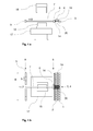
- Fig. 1a and 1b the basic structure of the device can be seen.
- the supply of the yarns or rovings takes place over a multiplicity of Unwinding stations, in which the fiber material is provided in the form of bobbins or bundles of yarn (so-called bobbins), and which are arranged in a plurality of rows 1,2 next to each other, one behind the other or one above the other.
- the coils can also, as shown in 1a form an upper and a lower row.
- the beginnings of the yarns or rovings 20 are shown schematically only in the respectively used area for the unwinding stations 3,4 used. All other beginnings are threaded to the corresponding yarn transfer points 14, so that they can be detected by the associated grippers in the pick-up positions 9. Such a thing is called together as a creel.
- the grippers 5 are shown in their maximum positions 8, which in this case also correspond to the starting positions.
- the clamping width of a gripper is b and the total clamping width of all grippers is B. Even if only equal width gripper are shown, of course, grippers with different widths are possible.
- the grippers do not necessarily have their maximum and pickup positions in a line.
- the second mold is not shown in plan view. And a corresponding movement or lowering device for the second mold is not shown separately.
- a gripper 6 is in pick-up position and fetches the yarns or rovings corresponding to its arrangement in the device by grasping their beginnings.
- the gripper is displaceable by a guide device 7, for example a linkage or a piston.
- the grippers can move individually, but only linearly and on parallel paths next to each other between the pick-up position and the maximum position, thus enabling simple automation and fast parallel movement.
- several unwinding stations can be combined into one group and assigned to a gripper.
- a gripper can grab several yarns or rovings together. In any case, at least as many unwinding stations as grippers should be provided.
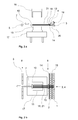
- Fig. 2a and 2b represent the spanned yarns or rovings 21, which the gripper 10 has pulled out by the method in its intermediate position. This can be assisted by actively powered unwinding.
- the intermediate position is close to the outer contour of the molds or near the later position of the outer contour when the molds are brought into their draping position.
- Binder material 18, for example in the form of binder threads or binder webs, can also be stretched by the gripper together with the yarns or rovings. There may also be an upper and a lower row of unwind stations, as shown, so that the binder material is stretched between the upper and lower groups of yarns or rovings.
- the binder material When pulling out, the binder material can be preactivated in the area of the yarn transfer points 14, in particular by a heating device, so that the yarns or rovings are already somewhat fixed to one another at the beginning of draping.
- a spreading device can be provided in the area of the yarn transfer points, which can be designed as a kind of comb with one or more rows of tines. This ensures that the yarns or rovings lie next to each other across the board and do not slip sideways even during subsequent draping.
- the spreader may also be displaceable along the yarn paths or along the gripper paths. Another possibility for a yarn tension measuring device 13 is shown.
- Draping is the forming or shaping of yarns or rovings with the aid of a molding tool. Draping may be accomplished in one or more stages by moving the molding tool or dies simultaneously or sequentially into the plyed or roving ply. During draping, it is advantageous to regulate the yarn tensions, in particular to keep them constant. That is, as much yarn or roving is dispensed as is necessary for draping at the corresponding location of the forming tool. To achieve this, brake and coupling devices may be provided. Preferably, each unwinding station or each group of unwinding stations is assigned a corresponding control. This prevents the yarns or rovings from being overloaded or loosely laid. The yarn tensions can also be measured by suitable measuring devices in the area of the yarn transfer points and / or between the unwinding stations and the yarn transfer points. The value of the yarn tensions is preferably between 1 and 50 N / m 2 .
- Fig. 3a and 3b the condition is shown after the first draping. From the lift table 17, the first mold 15 'was moved to the draping position. As a result, the yarns or rovings 22 are deflected and draped over the forming tool 15 '. The gripper 10 fixes the beginnings of the yarns near the outer contour of the molding tool 15 '. After this step, binder material or rovings can alternatively or additionally be applied or sprayed onto the yarns or rovings.
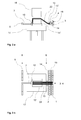
- the yarns or rovings are further draped or reshaped using the second forming tool 16 ', which has been moved to its draping position ( Fig . 4a and 4b ).
- the interaction of the two molds, between which the location of yarns or rovings is, a precise shape is possible.
- the molds can also be pressed together and one, preferably the second, or both molds can be heated, so that the binder material is activated and the yarns or rovings are dimensionally stable fixed to a layer.
- Simultaneously with or after fixing the yarns or rovings are separated on both sides of the molds, ie between gripper and mold and between yarn transfer points and mold.
- the separator may be connected to the first or second mold. It is advantageous if the separation takes place at least on the side of the yarn transfer points close to the mold. This results in little waste of expensive fiber material and less reworking of the fiber preform is necessary.
- the separated yarns or rovings 23 can be withdrawn and wound up again by means of a rewinding device or temporarily stored by appropriate yarn guidance.
- the rewinding takes place in such a way that again starts of the yarns or rovings in the area of the yarn transfer points 14 come to lie so that they can be picked up by the grippers without too much waste material being produced. Sensors can be used to record the beginnings.
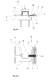
- Fig. 6a and 6b show the first and second mold 15,16 in a rotated position. Here they were turned 90 °. But it is also another angle of rotation, for example, about 30 °, 45 °, 60 °, or a tilt possible. The angle of rotation is preferably between 10 and 170 °. This depends on how and with which fiber orientation the further layer of yarns or rovings is to be applied.
- the yarns or rovings of the further layer are stretched to an intermediate position of the grippers and draped by moving the first and second dies 15 ', 16' to the draping position.
- Fig. 7a and 7b show the device after the yarns or rovings have been separated.
- the grippers 11 used are in an intermediate position.
- the grippers 11 may also be at different intermediate positions.
- the further location Yarns or rovings and possibly of binder material can also be fixed dimensionally stable by heating and / or pressing and connected to the first layer. Together they form the fiber preform 28.
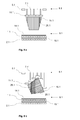
- Fig. 8a another embodiment is shown, as it can be used for example in the manufacture of fiber preforms for hoods use.
- the used grippers 10.1 are at an intermediate position, the unnecessary grippers 5.1 are in the maximum position 8.1.
- On the first mold 15.1 a first layer of yarns or rovings is draped and fixed.
- the second mold is not shown.
- the stocking of the yarns or rovings takes place in the unwinding stations 1.1, 2.1.
- a binder material supply 19.1 and the yarn transfer points 14.1 are present.
- Fig. 8b is another layer 26.1 draped on the turned mold.
- the used gripper 11.1 stand along the outer contour of the mold and form it as accurately as possible. Narrower or different width grippers can be used for even more precise adjustment.
- Fig. 8c shows how yet another layer was applied.
- the used grippers 12.1 are again along the outer contour. After fixing, the layers together form the fiber preform 28.1.
Landscapes
- Engineering & Computer Science (AREA)
- Mechanical Engineering (AREA)
- Chemical & Material Sciences (AREA)
- Composite Materials (AREA)
- Robotics (AREA)
- Reinforced Plastic Materials (AREA)
- Moulding By Coating Moulds (AREA)
- Yarns And Mechanical Finishing Of Yarns Or Ropes (AREA)
Applications Claiming Priority (2)
| Application Number | Priority Date | Filing Date | Title |
|---|---|---|---|
| DE102011007021A DE102011007021A1 (de) | 2011-04-08 | 2011-04-08 | Vorrichtung und Verfahren zur Herstellung von Faservorformlingen, die insbesondere eine Vorstufe bei der Herstellung von faserverstärkten Kunststoff-Bauteilen darstellen |
| PCT/EP2012/051290 WO2012136392A1 (de) | 2011-04-08 | 2012-01-27 | Vorrichtung und verfahren zur herstellung von faservorformlingen, die insbesondere eine vorstufe bei der herstellung von faserverstärkten kunststoff-bauteilen darstellen |
Publications (2)
| Publication Number | Publication Date |
|---|---|
| EP2694264A1 EP2694264A1 (de) | 2014-02-12 |
| EP2694264B1 true EP2694264B1 (de) | 2015-08-19 |
Family
ID=45566985
Family Applications (1)
| Application Number | Title | Priority Date | Filing Date |
|---|---|---|---|
| EP12702787.8A Active EP2694264B1 (de) | 2011-04-08 | 2012-01-27 | Vorrichtung und verfahren zur herstellung von faservorformlingen, die insbesondere eine vorstufe bei der herstellung von faserverstärkten kunststoff-bauteilen darstellen |
Country Status (6)
| Country | Link |
|---|---|
| US (1) | US9694547B2 (enExample) |
| EP (1) | EP2694264B1 (enExample) |
| JP (1) | JP6000330B2 (enExample) |
| CN (1) | CN103476560B (enExample) |
| DE (1) | DE102011007021A1 (enExample) |
| WO (1) | WO2012136392A1 (enExample) |
Families Citing this family (13)
| Publication number | Priority date | Publication date | Assignee | Title |
|---|---|---|---|---|
| DE102010015199B9 (de) | 2010-04-16 | 2013-08-01 | Compositence Gmbh | Faserführungsvorrichtung und Vorrichtung zum Aufbau eines dreidimensionalen Vorformlings |
| DE102011100640A1 (de) | 2011-05-05 | 2012-11-08 | Compositence Gmbh | Verfahren und Vorrichtung zum Herstellen von Fasergelegen und Bauteilvorformlingen aus Fasern |
| DE102012007439A1 (de) | 2012-04-13 | 2013-10-17 | Compositence Gmbh | Legekopf und Vorrichtung und Verfahren zum Aufbau eines dreidimensionalen Vorformlings für ein Bauteil aus einem Faserverbundwerkstoff |
| JP6073499B2 (ja) * | 2012-12-28 | 2017-02-01 | コンポジテンス ゲーエムベーハーCompositence GmbH | 二つのステップで三次元繊維ファブリック及び繊維製の構造部品プリフォームを製造するための方法及び装置 |
| DE102013009047A1 (de) * | 2013-05-28 | 2014-12-04 | Daimler Ag | Verfahren zur Herstellung eines geometriestabilen Vorformlings aus einem Faserhalbzeug und Vorrichtung zum Endformen eines Faserhalbzeugs |
| GB2533567A (en) * | 2014-12-19 | 2016-06-29 | Airbus Operations Ltd | Method of forming laminar composite charge |
| DE102015204417A1 (de) * | 2015-03-12 | 2016-09-15 | Audi Ag | Schneideinheit mit einer Klinge zum Trennen zumindest einer Faser, insbesondere zur Herstellung von Faservorformlingen |
| US10746640B2 (en) * | 2017-03-21 | 2020-08-18 | Textron Innovations Inc. | Methods of making a tubular specimen with a predetermined wrinkle defect |
| US10744727B2 (en) | 2017-03-21 | 2020-08-18 | Textron Innovations Inc. | Methods of making a specimen with a predetermined wrinkle defect |
| US10688711B2 (en) * | 2017-07-14 | 2020-06-23 | The Boeing Company | Heat blanket assembly for forming a composite charge |
| US10703055B2 (en) | 2017-07-14 | 2020-07-07 | The Boeing Company | Clamping system for holding a composite charge during forming over a forming mandrel |
| CN109808104B (zh) * | 2019-04-04 | 2020-10-16 | 吉林大学 | 一种用于多点模具成形smc复合材料工件的消隙机构 |
| US12485575B2 (en) | 2022-08-16 | 2025-12-02 | Rohr, Inc. | Forming a preform into a shaped body |
Family Cites Families (15)
| Publication number | Priority date | Publication date | Assignee | Title |
|---|---|---|---|---|
| DK92684D0 (da) * | 1983-04-20 | 1984-02-23 | Itt | Profil eller konstruktionselement af et armeret kompositmateriale samt maskine og fremgangsmade til fremstilling heraf |
| US6045651A (en) * | 1993-09-07 | 2000-04-04 | The Boeing Company | Hand assisted lamination system |
| DE19922799B4 (de) * | 1999-05-18 | 2014-06-12 | Bayerische Motoren Werke Aktiengesellschaft | Verfahren zur Herstellung eines Kunststoffformteils |
| US6814916B2 (en) * | 2002-08-30 | 2004-11-09 | The Boeing Company | Forming method for composites |
| US7137182B2 (en) * | 2002-11-22 | 2006-11-21 | The Boeing Company | Parallel configuration composite material fabricator |
| JP4677950B2 (ja) * | 2006-03-31 | 2011-04-27 | 株式会社豊田自動織機 | 三次元繊維構造体及び複合材並びに三次元繊維構造体の製造方法 |
| JP4775090B2 (ja) * | 2006-04-14 | 2011-09-21 | 株式会社豊田自動織機 | 繊維強化複合材の製造方法 |
| FR2912953B1 (fr) | 2007-02-28 | 2009-04-17 | Coriolis Composites Sa | Machine d'application de fibres avec tubes flexibles d'acheminement de fibres |
| DE102007058727A1 (de) * | 2007-12-06 | 2009-06-10 | Airbus Deutschland Gmbh | Verfahren zur Herstellung eines FVW-Vorformlings aus einem Laminat mit zumindest zwei Prepreg-Lagen sowie Herstellungsvorrichtung für ein derartiges Verfahren |
| CN101462358B (zh) * | 2007-12-19 | 2013-09-11 | 维斯塔斯风力系统有限公司 | 一种制备预成型件的设备 |
| DE102008011658A1 (de) | 2008-02-28 | 2009-09-03 | Daimler Ag | Verfahren zum Herstellen eines Faserverbund-Bauteils und Faserverbund-Bauteil |
| DE102008042574B4 (de) | 2008-10-02 | 2010-06-10 | Airbus Deutschland Gmbh | Vorrichtung zum Ablegen und Drapieren von Abschnitten einer Verstärkungsfaserstruktur zur Herstellung eines Profilvorformlings sowie Verfahren |
| US20100200168A1 (en) * | 2009-02-06 | 2010-08-12 | Ingersoll Machine Tools, Inc. | Fiber delivery apparatus and system having a creel and fiber placement head sans fiber redirect |
| DE102009042384B4 (de) * | 2009-09-21 | 2013-08-08 | Liba Maschinenfabrik Gmbh | Verfahren und Einrichtung zum Aufbringen einer unidirektionalen Faserlage auf eine sich bewegende Unterstützung und Verfahren zum Herstellen eines Multiaxialgeleges |
| DE102011007018A1 (de) * | 2011-04-08 | 2012-10-11 | Voith Patent Gmbh | Vorrichtung und Verfahren zur Herstellung von Faservorformlingen, die insbesondere eine Vorstufe bei der Herstellung von faserverstärkten Kunststoff-Bauteilen darstellen |
-
2011
- 2011-04-08 DE DE102011007021A patent/DE102011007021A1/de not_active Withdrawn
-
2012
- 2012-01-27 WO PCT/EP2012/051290 patent/WO2012136392A1/de not_active Ceased
- 2012-01-27 EP EP12702787.8A patent/EP2694264B1/de active Active
- 2012-01-27 CN CN201280017367.3A patent/CN103476560B/zh active Active
- 2012-01-27 JP JP2014503036A patent/JP6000330B2/ja active Active
-
2013
- 2013-10-08 US US14/048,756 patent/US9694547B2/en active Active
Also Published As
| Publication number | Publication date |
|---|---|
| EP2694264A1 (de) | 2014-02-12 |
| CN103476560A (zh) | 2013-12-25 |
| US9694547B2 (en) | 2017-07-04 |
| JP2014512988A (ja) | 2014-05-29 |
| JP6000330B2 (ja) | 2016-09-28 |
| WO2012136392A1 (de) | 2012-10-11 |
| CN103476560B (zh) | 2016-08-17 |
| US20140131914A1 (en) | 2014-05-15 |
| DE102011007021A1 (de) | 2012-10-11 |
Similar Documents
| Publication | Publication Date | Title |
|---|---|---|
| EP2694263B1 (de) | Vorrichtung und verfahren zur herstellung von faservorformlingen, die insbesondere eine vorstufe bei der herstellung von faserverstärkten kunststoff-bauteilen darstellen | |
| EP2694264B1 (de) | Vorrichtung und verfahren zur herstellung von faservorformlingen, die insbesondere eine vorstufe bei der herstellung von faserverstärkten kunststoff-bauteilen darstellen | |
| EP2694262B1 (de) | Vorrichtung und verfahren zur herstellung von faservorformlingen, die insbesondere eine vorstufe bei der herstellung von faserverstärkten kunststoff-bauteilen darstellen | |
| DE102010015199B4 (de) | Faserführungsvorrichtung und Vorrichtung zum Aufbau eines dreidimensionalen Vorformlings | |
| EP2280820B1 (de) | Verfahren zur herstellung eines fvw/fvk-bauteils aus rovings mit einem formwerkzeug und formwerkzeug zur durchführung des verfahrens | |
| DE60118048T2 (de) | Verfahren und Anlage zur kontinuierlichen Herstellung eines H-formigen Gegenstands aus faserverstärktem Kunststoff | |
| EP3386735B1 (de) | Ablagevorrichtung für faserrovings | |
| DE10250826B4 (de) | Verfahren zur Herstellung eines dreidimensionalen Preforms | |
| EP3122527B1 (de) | Verfahren zur herstellung eines faservorformlings für ein faserverbundbauteil | |
| DE102012218178A1 (de) | Vorrichtung zur Herstellung von Faservorformlingen, die insbesondere eine Vorstufe bei der Herstellung von faserverstärkten Kunststoffbauteilen darstellen | |
| EP3268173B1 (de) | Schneideinheit mit einer klinge zum trennen zumindest einer faser, insbesondere zur herstellung von faservorformlingen | |
| WO2012136391A1 (de) | Vorrichtung und verfahren zur herstellung von faservorformlingen, die insbesondere eine vorstufe bei der herstellung von faserverstärkten kunststoff-bauteilen darstellen | |
| DE102013104609B4 (de) | Nestingablage | |
| EP1568473B1 (de) | Verfahren und Vorrichtung zur Herstellung eines mit Endlosfasern verstärkten Polymer-Formteils | |
| EP3012093B1 (de) | Verfahren und anordnung zur herstellung einer blattfeder | |
| DE102015109103B3 (de) | Anordnung sowie Verfahren zum Vernähen eines Faserwerkstoffrohlings | |
| WO2014053305A1 (de) | Vorrichtung zur herstellung von faservorformlingen, die insbesondere eine vorstufe bei der herstellung von faserverstärkten kunststoffbauteilen darstellen | |
| WO2014012774A1 (de) | Vorrichtung und verfahren zur herstellung von faserverstärkten kunststoffbauteilen | |
| EP0800449B1 (de) | Verfahren und vorrichtung zur herstellung von verstärkungseinlagen für werkstoffverbunde, insbesondere schleif- oder trennscheiben | |
| WO2014053306A1 (de) | Vorrichtung zur herstellung von faservorformlingen, die insbesondere eine vorstufe bei der herstellung von faserverstärkten kunststoffbauteilen darstellen |
Legal Events
| Date | Code | Title | Description |
|---|---|---|---|
| PUAI | Public reference made under article 153(3) epc to a published international application that has entered the european phase |
Free format text: ORIGINAL CODE: 0009012 |
|
| 17P | Request for examination filed |
Effective date: 20131108 |
|
| AK | Designated contracting states |
Kind code of ref document: A1 Designated state(s): AL AT BE BG CH CY CZ DE DK EE ES FI FR GB GR HR HU IE IS IT LI LT LU LV MC MK MT NL NO PL PT RO RS SE SI SK SM TR |
|
| DAX | Request for extension of the european patent (deleted) | ||
| GRAP | Despatch of communication of intention to grant a patent |
Free format text: ORIGINAL CODE: EPIDOSNIGR1 |
|
| INTG | Intention to grant announced |
Effective date: 20150320 |
|
| RIC1 | Information provided on ipc code assigned before grant |
Ipc: B29C 70/38 20060101ALI20150306BHEP Ipc: B29B 11/16 20060101AFI20150306BHEP Ipc: B29C 70/54 20060101ALI20150306BHEP Ipc: B29C 70/56 20060101ALI20150306BHEP Ipc: B29C 70/20 20060101ALN20150306BHEP |
|
| GRAS | Grant fee paid |
Free format text: ORIGINAL CODE: EPIDOSNIGR3 |
|
| GRAA | (expected) grant |
Free format text: ORIGINAL CODE: 0009210 |
|
| AK | Designated contracting states |
Kind code of ref document: B1 Designated state(s): AL AT BE BG CH CY CZ DE DK EE ES FI FR GB GR HR HU IE IS IT LI LT LU LV MC MK MT NL NO PL PT RO RS SE SI SK SM TR |
|
| REG | Reference to a national code |
Ref country code: GB Ref legal event code: FG4D Free format text: NOT ENGLISH |
|
| REG | Reference to a national code |
Ref country code: CH Ref legal event code: EP |
|
| REG | Reference to a national code |
Ref country code: IE Ref legal event code: FG4D Free format text: LANGUAGE OF EP DOCUMENT: GERMAN |
|
| REG | Reference to a national code |
Ref country code: AT Ref legal event code: REF Ref document number: 743466 Country of ref document: AT Kind code of ref document: T Effective date: 20150915 |
|
| REG | Reference to a national code |
Ref country code: DE Ref legal event code: R096 Ref document number: 502012004204 Country of ref document: DE |
|
| REG | Reference to a national code |
Ref country code: NL Ref legal event code: FP |
|
| REG | Reference to a national code |
Ref country code: FR Ref legal event code: PLFP Year of fee payment: 5 |
|
| REG | Reference to a national code |
Ref country code: LT Ref legal event code: MG4D |
|
| PG25 | Lapsed in a contracting state [announced via postgrant information from national office to epo] |
Ref country code: GR Free format text: LAPSE BECAUSE OF FAILURE TO SUBMIT A TRANSLATION OF THE DESCRIPTION OR TO PAY THE FEE WITHIN THE PRESCRIBED TIME-LIMIT Effective date: 20151120 Ref country code: NO Free format text: LAPSE BECAUSE OF FAILURE TO SUBMIT A TRANSLATION OF THE DESCRIPTION OR TO PAY THE FEE WITHIN THE PRESCRIBED TIME-LIMIT Effective date: 20151119 Ref country code: LT Free format text: LAPSE BECAUSE OF FAILURE TO SUBMIT A TRANSLATION OF THE DESCRIPTION OR TO PAY THE FEE WITHIN THE PRESCRIBED TIME-LIMIT Effective date: 20150819 Ref country code: LV Free format text: LAPSE BECAUSE OF FAILURE TO SUBMIT A TRANSLATION OF THE DESCRIPTION OR TO PAY THE FEE WITHIN THE PRESCRIBED TIME-LIMIT Effective date: 20150819 Ref country code: FI Free format text: LAPSE BECAUSE OF FAILURE TO SUBMIT A TRANSLATION OF THE DESCRIPTION OR TO PAY THE FEE WITHIN THE PRESCRIBED TIME-LIMIT Effective date: 20150819 |
|
| PG25 | Lapsed in a contracting state [announced via postgrant information from national office to epo] |
Ref country code: SE Free format text: LAPSE BECAUSE OF FAILURE TO SUBMIT A TRANSLATION OF THE DESCRIPTION OR TO PAY THE FEE WITHIN THE PRESCRIBED TIME-LIMIT Effective date: 20150819 Ref country code: PT Free format text: LAPSE BECAUSE OF FAILURE TO SUBMIT A TRANSLATION OF THE DESCRIPTION OR TO PAY THE FEE WITHIN THE PRESCRIBED TIME-LIMIT Effective date: 20151221 Ref country code: IS Free format text: LAPSE BECAUSE OF FAILURE TO SUBMIT A TRANSLATION OF THE DESCRIPTION OR TO PAY THE FEE WITHIN THE PRESCRIBED TIME-LIMIT Effective date: 20151219 Ref country code: RS Free format text: LAPSE BECAUSE OF FAILURE TO SUBMIT A TRANSLATION OF THE DESCRIPTION OR TO PAY THE FEE WITHIN THE PRESCRIBED TIME-LIMIT Effective date: 20150819 Ref country code: PL Free format text: LAPSE BECAUSE OF FAILURE TO SUBMIT A TRANSLATION OF THE DESCRIPTION OR TO PAY THE FEE WITHIN THE PRESCRIBED TIME-LIMIT Effective date: 20150819 Ref country code: ES Free format text: LAPSE BECAUSE OF FAILURE TO SUBMIT A TRANSLATION OF THE DESCRIPTION OR TO PAY THE FEE WITHIN THE PRESCRIBED TIME-LIMIT Effective date: 20150819 |
|
| PG25 | Lapsed in a contracting state [announced via postgrant information from national office to epo] |
Ref country code: DK Free format text: LAPSE BECAUSE OF FAILURE TO SUBMIT A TRANSLATION OF THE DESCRIPTION OR TO PAY THE FEE WITHIN THE PRESCRIBED TIME-LIMIT Effective date: 20150819 Ref country code: EE Free format text: LAPSE BECAUSE OF FAILURE TO SUBMIT A TRANSLATION OF THE DESCRIPTION OR TO PAY THE FEE WITHIN THE PRESCRIBED TIME-LIMIT Effective date: 20150819 Ref country code: SK Free format text: LAPSE BECAUSE OF FAILURE TO SUBMIT A TRANSLATION OF THE DESCRIPTION OR TO PAY THE FEE WITHIN THE PRESCRIBED TIME-LIMIT Effective date: 20150819 Ref country code: CZ Free format text: LAPSE BECAUSE OF FAILURE TO SUBMIT A TRANSLATION OF THE DESCRIPTION OR TO PAY THE FEE WITHIN THE PRESCRIBED TIME-LIMIT Effective date: 20150819 |
|
| REG | Reference to a national code |
Ref country code: DE Ref legal event code: R097 Ref document number: 502012004204 Country of ref document: DE |
|
| PG25 | Lapsed in a contracting state [announced via postgrant information from national office to epo] |
Ref country code: RO Free format text: LAPSE BECAUSE OF FAILURE TO SUBMIT A TRANSLATION OF THE DESCRIPTION OR TO PAY THE FEE WITHIN THE PRESCRIBED TIME-LIMIT Effective date: 20150819 Ref country code: BE Free format text: LAPSE BECAUSE OF NON-PAYMENT OF DUE FEES Effective date: 20160131 |
|
| PLBE | No opposition filed within time limit |
Free format text: ORIGINAL CODE: 0009261 |
|
| STAA | Information on the status of an ep patent application or granted ep patent |
Free format text: STATUS: NO OPPOSITION FILED WITHIN TIME LIMIT |
|
| 26N | No opposition filed |
Effective date: 20160520 |
|
| PG25 | Lapsed in a contracting state [announced via postgrant information from national office to epo] |
Ref country code: SI Free format text: LAPSE BECAUSE OF FAILURE TO SUBMIT A TRANSLATION OF THE DESCRIPTION OR TO PAY THE FEE WITHIN THE PRESCRIBED TIME-LIMIT Effective date: 20150819 Ref country code: LU Free format text: LAPSE BECAUSE OF FAILURE TO SUBMIT A TRANSLATION OF THE DESCRIPTION OR TO PAY THE FEE WITHIN THE PRESCRIBED TIME-LIMIT Effective date: 20160127 |
|
| PG25 | Lapsed in a contracting state [announced via postgrant information from national office to epo] |
Ref country code: MC Free format text: LAPSE BECAUSE OF FAILURE TO SUBMIT A TRANSLATION OF THE DESCRIPTION OR TO PAY THE FEE WITHIN THE PRESCRIBED TIME-LIMIT Effective date: 20150819 |
|
| REG | Reference to a national code |
Ref country code: IE Ref legal event code: MM4A |
|
| REG | Reference to a national code |
Ref country code: FR Ref legal event code: PLFP Year of fee payment: 6 |
|
| PG25 | Lapsed in a contracting state [announced via postgrant information from national office to epo] |
Ref country code: IE Free format text: LAPSE BECAUSE OF NON-PAYMENT OF DUE FEES Effective date: 20160127 |
|
| PG25 | Lapsed in a contracting state [announced via postgrant information from national office to epo] |
Ref country code: MT Free format text: LAPSE BECAUSE OF FAILURE TO SUBMIT A TRANSLATION OF THE DESCRIPTION OR TO PAY THE FEE WITHIN THE PRESCRIBED TIME-LIMIT Effective date: 20150819 |
|
| REG | Reference to a national code |
Ref country code: FR Ref legal event code: PLFP Year of fee payment: 7 |
|
| REG | Reference to a national code |
Ref country code: AT Ref legal event code: MM01 Ref document number: 743466 Country of ref document: AT Kind code of ref document: T Effective date: 20170127 |
|
| PG25 | Lapsed in a contracting state [announced via postgrant information from national office to epo] |
Ref country code: SM Free format text: LAPSE BECAUSE OF FAILURE TO SUBMIT A TRANSLATION OF THE DESCRIPTION OR TO PAY THE FEE WITHIN THE PRESCRIBED TIME-LIMIT Effective date: 20150819 Ref country code: CY Free format text: LAPSE BECAUSE OF FAILURE TO SUBMIT A TRANSLATION OF THE DESCRIPTION OR TO PAY THE FEE WITHIN THE PRESCRIBED TIME-LIMIT Effective date: 20150819 Ref country code: AT Free format text: LAPSE BECAUSE OF NON-PAYMENT OF DUE FEES Effective date: 20170127 Ref country code: HU Free format text: LAPSE BECAUSE OF FAILURE TO SUBMIT A TRANSLATION OF THE DESCRIPTION OR TO PAY THE FEE WITHIN THE PRESCRIBED TIME-LIMIT; INVALID AB INITIO Effective date: 20120127 |
|
| PG25 | Lapsed in a contracting state [announced via postgrant information from national office to epo] |
Ref country code: MK Free format text: LAPSE BECAUSE OF FAILURE TO SUBMIT A TRANSLATION OF THE DESCRIPTION OR TO PAY THE FEE WITHIN THE PRESCRIBED TIME-LIMIT Effective date: 20150819 Ref country code: HR Free format text: LAPSE BECAUSE OF FAILURE TO SUBMIT A TRANSLATION OF THE DESCRIPTION OR TO PAY THE FEE WITHIN THE PRESCRIBED TIME-LIMIT Effective date: 20150819 Ref country code: TR Free format text: LAPSE BECAUSE OF FAILURE TO SUBMIT A TRANSLATION OF THE DESCRIPTION OR TO PAY THE FEE WITHIN THE PRESCRIBED TIME-LIMIT Effective date: 20150819 |
|
| PG25 | Lapsed in a contracting state [announced via postgrant information from national office to epo] |
Ref country code: BG Free format text: LAPSE BECAUSE OF FAILURE TO SUBMIT A TRANSLATION OF THE DESCRIPTION OR TO PAY THE FEE WITHIN THE PRESCRIBED TIME-LIMIT Effective date: 20150819 |
|
| PG25 | Lapsed in a contracting state [announced via postgrant information from national office to epo] |
Ref country code: AL Free format text: LAPSE BECAUSE OF FAILURE TO SUBMIT A TRANSLATION OF THE DESCRIPTION OR TO PAY THE FEE WITHIN THE PRESCRIBED TIME-LIMIT Effective date: 20150819 |
|
| REG | Reference to a national code |
Ref country code: DE Ref legal event code: R081 Ref document number: 502012004204 Country of ref document: DE Owner name: VOITH HYSTECH GMBH, DE Free format text: FORMER OWNER: VOITH PATENT GMBH, 89522 HEIDENHEIM, DE |
|
| PGFP | Annual fee paid to national office [announced via postgrant information from national office to epo] |
Ref country code: NL Payment date: 20250121 Year of fee payment: 14 |
|
| PGFP | Annual fee paid to national office [announced via postgrant information from national office to epo] |
Ref country code: DE Payment date: 20250121 Year of fee payment: 14 |
|
| PGFP | Annual fee paid to national office [announced via postgrant information from national office to epo] |
Ref country code: CH Payment date: 20250201 Year of fee payment: 14 |
|
| PGFP | Annual fee paid to national office [announced via postgrant information from national office to epo] |
Ref country code: FR Payment date: 20250127 Year of fee payment: 14 |
|
| PGFP | Annual fee paid to national office [announced via postgrant information from national office to epo] |
Ref country code: IT Payment date: 20250129 Year of fee payment: 14 Ref country code: GB Payment date: 20250128 Year of fee payment: 14 |
|
| REG | Reference to a national code |
Ref country code: NL Ref legal event code: PD Owner name: VOITH HYSTECH GMBH; DE Free format text: DETAILS ASSIGNMENT: CHANGE OF OWNER(S), ASSIGNMENT; FORMER OWNER NAME: VOITH PATENT GMBH Effective date: 20250619 |
|
| REG | Reference to a national code |
Ref country code: GB Ref legal event code: 732E Free format text: REGISTERED BETWEEN 20250605 AND 20250611 |