EP2693545B1 - Brennstoffzelle - Google Patents
Brennstoffzelle Download PDFInfo
- Publication number
- EP2693545B1 EP2693545B1 EP12762795.8A EP12762795A EP2693545B1 EP 2693545 B1 EP2693545 B1 EP 2693545B1 EP 12762795 A EP12762795 A EP 12762795A EP 2693545 B1 EP2693545 B1 EP 2693545B1
- Authority
- EP
- European Patent Office
- Prior art keywords
- electrode
- fuel cell
- fuel
- interlayer
- separator
- Prior art date
- Legal status (The legal status is an assumption and is not a legal conclusion. Google has not performed a legal analysis and makes no representation as to the accuracy of the status listed.)
- Not-in-force
Links
- 239000000446 fuel Substances 0.000 title claims description 106
- 239000010410 layer Substances 0.000 claims description 45
- 239000011229 interlayer Substances 0.000 claims description 39
- 239000007787 solid Substances 0.000 claims description 29
- 239000003792 electrolyte Substances 0.000 claims description 22
- 229910052759 nickel Inorganic materials 0.000 claims description 17
- 229910001233 yttria-stabilized zirconia Inorganic materials 0.000 claims description 12
- 229910002076 stabilized zirconia Inorganic materials 0.000 claims description 9
- 229910052719 titanium Inorganic materials 0.000 claims description 9
- CETPSERCERDGAM-UHFFFAOYSA-N ceric oxide Chemical compound O=[Ce]=O CETPSERCERDGAM-UHFFFAOYSA-N 0.000 claims description 8
- 229910000422 cerium(IV) oxide Inorganic materials 0.000 claims description 8
- 229910001316 Ag alloy Inorganic materials 0.000 claims description 7
- 229910001252 Pd alloy Inorganic materials 0.000 claims description 7
- 239000013078 crystal Substances 0.000 claims description 6
- 241000968352 Scandia <hydrozoan> Species 0.000 claims description 5
- HJGMWXTVGKLUAQ-UHFFFAOYSA-N oxygen(2-);scandium(3+) Chemical compound [O-2].[O-2].[O-2].[Sc+3].[Sc+3] HJGMWXTVGKLUAQ-UHFFFAOYSA-N 0.000 claims description 5
- 229910052688 Gadolinium Inorganic materials 0.000 claims description 4
- 238000004519 manufacturing process Methods 0.000 claims description 3
- PXHVJJICTQNCMI-UHFFFAOYSA-N nickel Substances [Ni] PXHVJJICTQNCMI-UHFFFAOYSA-N 0.000 description 45
- GWEVSGVZZGPLCZ-UHFFFAOYSA-N Titan oxide Chemical compound O=[Ti]=O GWEVSGVZZGPLCZ-UHFFFAOYSA-N 0.000 description 31
- 239000007789 gas Substances 0.000 description 17
- 239000010936 titanium Substances 0.000 description 16
- 230000002093 peripheral effect Effects 0.000 description 15
- 239000002737 fuel gas Substances 0.000 description 14
- 239000000463 material Substances 0.000 description 12
- 239000007800 oxidant agent Substances 0.000 description 11
- 230000001590 oxidative effect Effects 0.000 description 11
- 239000000470 constituent Substances 0.000 description 7
- 238000010248 power generation Methods 0.000 description 7
- 239000000843 powder Substances 0.000 description 6
- 229910002077 partially stabilized zirconia Inorganic materials 0.000 description 5
- 239000000919 ceramic Substances 0.000 description 4
- 230000000052 comparative effect Effects 0.000 description 4
- 239000001301 oxygen Substances 0.000 description 4
- 229910052760 oxygen Inorganic materials 0.000 description 4
- 238000012360 testing method Methods 0.000 description 3
- OGIDPMRJRNCKJF-UHFFFAOYSA-N titanium oxide Inorganic materials [Ti]=O OGIDPMRJRNCKJF-UHFFFAOYSA-N 0.000 description 3
- 239000004215 Carbon black (E152) Substances 0.000 description 2
- 229910002328 LaMnO3 Inorganic materials 0.000 description 2
- 229910026161 MgAl2O4 Inorganic materials 0.000 description 2
- NBIIXXVUZAFLBC-UHFFFAOYSA-N Phosphoric acid Chemical compound OP(O)(O)=O NBIIXXVUZAFLBC-UHFFFAOYSA-N 0.000 description 2
- 229910002370 SrTiO3 Inorganic materials 0.000 description 2
- PNEYBMLMFCGWSK-UHFFFAOYSA-N aluminium oxide Inorganic materials [O-2].[O-2].[O-2].[Al+3].[Al+3] PNEYBMLMFCGWSK-UHFFFAOYSA-N 0.000 description 2
- QVGXLLKOCUKJST-UHFFFAOYSA-N atomic oxygen Chemical compound [O] QVGXLLKOCUKJST-UHFFFAOYSA-N 0.000 description 2
- NFYLSJDPENHSBT-UHFFFAOYSA-N chromium(3+);lanthanum(3+);oxygen(2-) Chemical compound [O-2].[O-2].[O-2].[Cr+3].[La+3] NFYLSJDPENHSBT-UHFFFAOYSA-N 0.000 description 2
- 229910052593 corundum Inorganic materials 0.000 description 2
- 229930195733 hydrocarbon Natural products 0.000 description 2
- 150000002430 hydrocarbons Chemical class 0.000 description 2
- 239000000203 mixture Substances 0.000 description 2
- 229910000480 nickel oxide Inorganic materials 0.000 description 2
- GNRSAWUEBMWBQH-UHFFFAOYSA-N oxonickel Chemical compound [Ni]=O GNRSAWUEBMWBQH-UHFFFAOYSA-N 0.000 description 2
- -1 oxygen ions Chemical class 0.000 description 2
- 238000002360 preparation method Methods 0.000 description 2
- 229910052761 rare earth metal Inorganic materials 0.000 description 2
- 150000002910 rare earth metals Chemical class 0.000 description 2
- 239000002002 slurry Substances 0.000 description 2
- 229910052596 spinel Inorganic materials 0.000 description 2
- 229910001845 yogo sapphire Inorganic materials 0.000 description 2
- UGFAIRIUMAVXCW-UHFFFAOYSA-N Carbon monoxide Chemical compound [O+]#[C-] UGFAIRIUMAVXCW-UHFFFAOYSA-N 0.000 description 1
- BVKZGUZCCUSVTD-UHFFFAOYSA-L Carbonate Chemical compound [O-]C([O-])=O BVKZGUZCCUSVTD-UHFFFAOYSA-L 0.000 description 1
- MYMOFIZGZYHOMD-UHFFFAOYSA-N Dioxygen Chemical compound O=O MYMOFIZGZYHOMD-UHFFFAOYSA-N 0.000 description 1
- UFHFLCQGNIYNRP-UHFFFAOYSA-N Hydrogen Chemical compound [H][H] UFHFLCQGNIYNRP-UHFFFAOYSA-N 0.000 description 1
- 229910002204 La0.8Sr0.2MnO3 Inorganic materials 0.000 description 1
- 229910002254 LaCoO3 Inorganic materials 0.000 description 1
- 229910002321 LaFeO3 Inorganic materials 0.000 description 1
- 229910002331 LaGaO3 Inorganic materials 0.000 description 1
- 229910052772 Samarium Inorganic materials 0.000 description 1
- 229910000147 aluminium phosphate Inorganic materials 0.000 description 1
- 230000004888 barrier function Effects 0.000 description 1
- 239000011230 binding agent Substances 0.000 description 1
- 229910002091 carbon monoxide Inorganic materials 0.000 description 1
- 239000011195 cermet Substances 0.000 description 1
- 229910052802 copper Inorganic materials 0.000 description 1
- 238000005336 cracking Methods 0.000 description 1
- 230000007423 decrease Effects 0.000 description 1
- 229910001882 dioxygen Inorganic materials 0.000 description 1
- 238000007606 doctor blade method Methods 0.000 description 1
- 238000011156 evaluation Methods 0.000 description 1
- 229910052733 gallium Inorganic materials 0.000 description 1
- 239000011521 glass Substances 0.000 description 1
- 229910003437 indium oxide Inorganic materials 0.000 description 1
- PJXISJQVUVHSOJ-UHFFFAOYSA-N indium(iii) oxide Chemical compound [O-2].[O-2].[O-2].[In+3].[In+3] PJXISJQVUVHSOJ-UHFFFAOYSA-N 0.000 description 1
- 229910052742 iron Inorganic materials 0.000 description 1
- 229910052746 lanthanum Inorganic materials 0.000 description 1
- 239000007788 liquid Substances 0.000 description 1
- 229910000473 manganese(VI) oxide Inorganic materials 0.000 description 1
- 238000005259 measurement Methods 0.000 description 1
- 229910052751 metal Inorganic materials 0.000 description 1
- 239000002184 metal Substances 0.000 description 1
- 238000000034 method Methods 0.000 description 1
- 229910000749 nitanium Inorganic materials 0.000 description 1
- 229910052763 palladium Inorganic materials 0.000 description 1
- 239000005518 polymer electrolyte Substances 0.000 description 1
- 238000012827 research and development Methods 0.000 description 1
- 229910052707 ruthenium Inorganic materials 0.000 description 1
- 238000005245 sintering Methods 0.000 description 1
- 239000002904 solvent Substances 0.000 description 1
- XLYOFNOQVPJJNP-UHFFFAOYSA-N water Substances O XLYOFNOQVPJJNP-UHFFFAOYSA-N 0.000 description 1
- RUDFQVOCFDJEEF-UHFFFAOYSA-N yttrium(III) oxide Inorganic materials [O-2].[O-2].[O-2].[Y+3].[Y+3] RUDFQVOCFDJEEF-UHFFFAOYSA-N 0.000 description 1
Images


Classifications
-
- H—ELECTRICITY
- H01—ELECTRIC ELEMENTS
- H01M—PROCESSES OR MEANS, e.g. BATTERIES, FOR THE DIRECT CONVERSION OF CHEMICAL ENERGY INTO ELECTRICAL ENERGY
- H01M8/00—Fuel cells; Manufacture thereof
- H01M8/10—Fuel cells with solid electrolytes
- H01M8/12—Fuel cells with solid electrolytes operating at high temperature, e.g. with stabilised ZrO2 electrolyte
- H01M8/1213—Fuel cells with solid electrolytes operating at high temperature, e.g. with stabilised ZrO2 electrolyte characterised by the electrode/electrolyte combination or the supporting material
- H01M8/1226—Fuel cells with solid electrolytes operating at high temperature, e.g. with stabilised ZrO2 electrolyte characterised by the electrode/electrolyte combination or the supporting material characterised by the supporting layer
-
- H—ELECTRICITY
- H01—ELECTRIC ELEMENTS
- H01M—PROCESSES OR MEANS, e.g. BATTERIES, FOR THE DIRECT CONVERSION OF CHEMICAL ENERGY INTO ELECTRICAL ENERGY
- H01M8/00—Fuel cells; Manufacture thereof
- H01M8/02—Details
- H01M8/0202—Collectors; Separators, e.g. bipolar separators; Interconnectors
- H01M8/0204—Non-porous and characterised by the material
- H01M8/0206—Metals or alloys
-
- H—ELECTRICITY
- H01—ELECTRIC ELEMENTS
- H01M—PROCESSES OR MEANS, e.g. BATTERIES, FOR THE DIRECT CONVERSION OF CHEMICAL ENERGY INTO ELECTRICAL ENERGY
- H01M8/00—Fuel cells; Manufacture thereof
- H01M8/02—Details
- H01M8/0202—Collectors; Separators, e.g. bipolar separators; Interconnectors
- H01M8/0204—Non-porous and characterised by the material
- H01M8/0223—Composites
- H01M8/0228—Composites in the form of layered or coated products
-
- H—ELECTRICITY
- H01—ELECTRIC ELEMENTS
- H01M—PROCESSES OR MEANS, e.g. BATTERIES, FOR THE DIRECT CONVERSION OF CHEMICAL ENERGY INTO ELECTRICAL ENERGY
- H01M8/00—Fuel cells; Manufacture thereof
- H01M8/02—Details
- H01M8/0202—Collectors; Separators, e.g. bipolar separators; Interconnectors
- H01M8/0247—Collectors; Separators, e.g. bipolar separators; Interconnectors characterised by the form
- H01M8/0256—Vias, i.e. connectors passing through the separator material
-
- H—ELECTRICITY
- H01—ELECTRIC ELEMENTS
- H01M—PROCESSES OR MEANS, e.g. BATTERIES, FOR THE DIRECT CONVERSION OF CHEMICAL ENERGY INTO ELECTRICAL ENERGY
- H01M8/00—Fuel cells; Manufacture thereof
- H01M8/10—Fuel cells with solid electrolytes
- H01M8/12—Fuel cells with solid electrolytes operating at high temperature, e.g. with stabilised ZrO2 electrolyte
- H01M8/1213—Fuel cells with solid electrolytes operating at high temperature, e.g. with stabilised ZrO2 electrolyte characterised by the electrode/electrolyte combination or the supporting material
-
- H—ELECTRICITY
- H01—ELECTRIC ELEMENTS
- H01M—PROCESSES OR MEANS, e.g. BATTERIES, FOR THE DIRECT CONVERSION OF CHEMICAL ENERGY INTO ELECTRICAL ENERGY
- H01M8/00—Fuel cells; Manufacture thereof
- H01M8/10—Fuel cells with solid electrolytes
- H01M8/12—Fuel cells with solid electrolytes operating at high temperature, e.g. with stabilised ZrO2 electrolyte
- H01M2008/1293—Fuel cells with solid oxide electrolytes
-
- Y—GENERAL TAGGING OF NEW TECHNOLOGICAL DEVELOPMENTS; GENERAL TAGGING OF CROSS-SECTIONAL TECHNOLOGIES SPANNING OVER SEVERAL SECTIONS OF THE IPC; TECHNICAL SUBJECTS COVERED BY FORMER USPC CROSS-REFERENCE ART COLLECTIONS [XRACs] AND DIGESTS
- Y02—TECHNOLOGIES OR APPLICATIONS FOR MITIGATION OR ADAPTATION AGAINST CLIMATE CHANGE
- Y02E—REDUCTION OF GREENHOUSE GAS [GHG] EMISSIONS, RELATED TO ENERGY GENERATION, TRANSMISSION OR DISTRIBUTION
- Y02E60/00—Enabling technologies; Technologies with a potential or indirect contribution to GHG emissions mitigation
- Y02E60/30—Hydrogen technology
- Y02E60/50—Fuel cells
Definitions
- the present invention relates to a fuel cell.
- the present invention relates to a solid oxide fuel cell.
- fuel cells include solid oxide fuel cells (SOFC), molten carbonate fuel cells, phosphoric acid fuel cells and polymer electrolyte fuel cells.
- SOFC solid oxide fuel cells
- molten carbonate fuel cells molten carbonate fuel cells
- phosphoric acid fuel cells molten carbonate fuel cells
- polymer electrolyte fuel cells solid oxide fuel cells
- solid oxide fuel cells do not necessarily require the use of a liquid component and can be internally modified when a hydrocarbon fuel is used. Therefore, research and development on solid oxide fuel cells are vigorously conducted.
- the solid oxide fuel cell includes a power generating element having a solid oxide electrolyte layer, and a fuel electrode and an air electrode which hold the solid oxide electrolyte layer therebetween.
- a separator which dividedly forms a channel for supplying a fuel gas is arranged on the fuel electrode.
- An interconnector for drawing the fuel electrode to outside is provided in the separator.
- a separator which dividedly forms a channel for supplying an oxidant gas is arranged on the air electrode.
- An interconnector for drawing the air electrode to outside is provided in the separator.
- WO-A-2004/088783 describes, as a constituent material of a fuel electrode, yttria stabilized zirconia (YSZ) containing at least one metal selected from Ni, Cu, Fe, Ru and Pd.
- YSZ yttria stabilized zirconia
- WO-A-2004/088783 describes, as a constituent material of an interconnector, a glass containing an Ag-Pd alloy.
- the present invention has been devised in view of the situation described above, and we have appreciated that it would be desirable to provide a fuel cell having a long product life.
- Example fuel cells are described in patent documents EP1624521A , EP1353391A , and US2007/0003815A .
- a fuel cell according to the present invention includes a power generating element, a separator and an interconnector.
- the power generating element has a solid oxide electrolyte layer, a first electrode and a second electrode.
- the first electrode is arranged on one principal surface of the solid oxide electrolyte layer.
- the second electrode is arranged on the other principal surface of the solid oxide electrolyte layer.
- the separator is arranged on the first electrode. The separator dividedly forms a channel facing the first electrode.
- the interconnector is connected to the first electrode.
- the first electrode contains Ni.
- the interconnector has a portion formed of Ag or an Ag-Pd alloy.
- the fuel cell according to the present invention further includes an interlayer.
- the interlayer is arranged between the portion formed of Ag or an Ag alloy and the first electrode.
- the interlayer is formed of an oxide comprising a NiTiO 3 crystal phase.
- the interlayer further contains a NiO crystal phase during manufacturing of the fuel cell.
- the molar ratio of Ni and Ti (Ni : Ti) in the interlayer is in a range of 62 : 38 to 95 : 5.
- the first electrode is formed of yttria stabilized zirconia containing Ni, scandia stabilized zirconia containing Ni, Ni-containing ceria doped with Gd or Ni-containing ceria doped with Sm.
- the interconnector has a portion formed of an Ag-Pd alloy.
- a fuel cell embodying to the present invention may have a long product life.
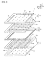
- FIG. 1 is a schematic exploded perspective view of a fuel cell according to a first embodiment.
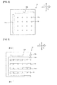
- FIG. 2 is a schematic plan view of a first separator body in the first embodiment.
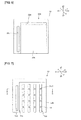
- FIG. 3 is a schematic plan view of a first channel forming member in the first embodiment.
- FIG. 4 is a schematic plan view of an air electrode layer in the first embodiment.
- FIG. 5 is a schematic plan view of a solid oxide electrolyte layer in the first embodiment.
- FIG. 6 is a schematic plan view of a fuel electrode layer in the first embodiment.
- FIG. 7 is a schematic plan view of a second channel forming member in the first embodiment.
- FIG. 8 is a schematic plan view of a second separator body in the first embodiment.
- FIG. 9 is a schematic sectional view of the fuel cell in the line IX-IX in FIG. 3 .
- FIG. 10 is a schematic sectional view of the fuel cell in the line X-X in FIG. 7 .
- a fuel cell 1 of this embodiment includes a first separator 10, a power generating element 30 and a second separator 50.
- the first separator 10, the power generating element 30 and the second separator 50 are laminated in this order.
- the fuel cell 1 of this embodiment includes only one power generating element 30.
- the present invention is not limited to this configuration.
- the fuel cell 1 of the present invention may include a plurality of power generating elements. In this case, adjacent power generating elements are isolated from each other by the separator.
- the power generating element 30 is a portion where an oxidant gas supplied from an oxidant gas channel (manifold for oxidant gas) 61 and a fuel gas supplied from a fuel gas channel (manifold for fuel gas) 62 react with each other to generate power.
- the oxidant gas can be formed from, for example, an oxygen-containing gas such as air or oxygen gas.
- the fuel gas may be a gas containing a hydrogen gas, or a hydrocarbon gas such as a carbon monoxide gas, etc.
- the power generating element 30 includes a solid oxide electrolyte layer 31.
- the solid oxide electrolyte layer 31 is preferably one having high ionic conductivity.
- the solid oxide electrolyte layer 31 can be formed from, for example, stabilized zirconia or partially stabilized zirconia.
- stabilized zirconia include 10 mol% yttria stabilized zirconia (10YSZ) and 11 mol% scandia stabilized zirconia (11ScSZ).
- Specific examples of partially stabilized zirconia include 3 mol% yttria partially stabilized zirconia (3YSZ).
- the solid oxide electrolyte layer 31 can also be formed from, for example, a ceria-based oxide doped with Sm, Gd and the like, or a perovskite type oxide, such as La 0.8 Sr 0.2 Ga 0.8 Mg 0.8 Mg 0.2 O (3- ⁇ ) , which has LaGaO 3 as a base and in which La and Ga are partially substituted with Sr and Mg, respectively.
- a perovskite type oxide such as La 0.8 Sr 0.2 Ga 0.8 Mg 0.8 Mg 0.2 O (3- ⁇ ) , which has LaGaO 3 as a base and in which La and Ga are partially substituted with Sr and Mg, respectively.
- Through holes 31a and 31b forming parts of channels 61 and 62 are formed in the solid oxide electrolyte layer 31 as shown in FIG. 5 .
- the solid oxide electrolyte layer 31 is held between an air electrode layer 32 and a fuel electrode layer 33. That is, the air electrode layer 32 is formed on one principal surface of the solid oxide electrolyte layer 31, and the fuel electrode layer 33 is formed on the other principal surface.
- the air electrode layer 32 has an air electrode 32a and a peripheral portion 32b. Through holes 32c and 32d forming parts of channels 61 and 62 are formed in the peripheral portion 32b.
- the air electrode 32a is a cathode. In the air electrode 32a, oxygen captures electrons to form oxygen ions.
- the air electrode 32a is preferably one that is porous, has high electron conductivity and is hard to undergo a solid-solid reaction with the solid oxide electrolyte layer 31 etc. at a high temperature.
- the air electrode 32a can be formed from, for example, scandia stabilized zirconia (ScSZ), ceria doped with Gd, indium oxide doped with Sn, a PrCoO 3 -based oxide, a LaCoO 3 -based oxide, a LaFeO 3 -based oxide, a LaCoFeO 3 -based oxide or a LaMnO 3 -based oxide.
- Specific examples of the LaMnO 3 -based oxide include La 0.8 Sr 0.2 MnO 3 (common name: LSM) and La 0.6 Ca 0.4 MnO 3 (common name: LCM).
- the peripheral portion 32b can be formed from, for example, a material similar to that of first and second separator bodies 11 and 51 described below.
- the fuel electrode layer 33 has a fuel electrode 33a and a peripheral portion 33b. Through holes 33c and 33d forming parts of channels 61 and 62 are formed in the peripheral portion 33b.
- the fuel electrode 33a is an anode. In the fuel electrode 33a, oxygen ions and a fuel gas react with each other to release electrons.
- the air electrode 33a is preferably one that is porous, has high electron conductivity and is hard to undergo a solid-solid reaction with the solid oxide electrolyte layer 31 etc. at a high temperature.
- the fuel electrode 33a contains Ni.
- the fuel electrode 33a can be formed from, for example, yttria stabilized zirconia containing Ni, scandia stabilized zirconia containing Ni (it may also be cermet), Ni-containing ceria doped with Gd or Ni-containing ceria doped with Sm.
- the content of Ni in the fuel electrode 33a may be, for example, about 40% by mass to 80% by mass in terms of an oxide.
- the first separator 10 is arranged on the air electrode layer 32 of the power generating element 30.
- the first separator 10 has a function to form a channel 12a for supplying to the air electrode 32a an oxidant gas supplied from the oxidant gas channel 61.
- the first separator also has a function to separate a fuel gas and an oxidant gas.
- the first separator 10 has a first separator body 11 and a first channel forming member 12.
- the first separator body 11 is arranged on the air electrode 32a. Through holes 11a and 11b forming parts of channels 61 and 62 are formed in the first separator body 11.
- the first channel forming member 12 is arranged between the first separator body 11 and the air electrode layer 32.
- the first channel forming member 12 has a peripheral portion 12b and a plurality of linear projections 12c.
- a through hole 12d forming part of the fuel channel 62 is formed in the peripheral portion 12b.
- Each of a plurality of linear projections 12c is provided so as to protrude toward the air electrode layer 32 side from a surface of the first separator body 11 on the air electrode layer 32 side.
- Each of a plurality of linear projections 12c is provided along an x direction.
- a plurality of linear projections 12c are arranged at intervals from one another along a y direction.
- the channel 12a is dividedly formed between adjacent linear projections 12c and between the linear projection 12c and the peripheral portion 12b.
- the materials of the first separator body 11 and the first channel forming member 12 are not particularly limited.
- Each of the first separator body 11 and the first channel forming member 12 can be formed from, for example, stabilized zirconia or partially stabilized zirconia.
- Each of the first separator body 11 and the first channel forming member 12 can also be formed from, for example, a conductive ceramic such as lanthanum chromite containing a rare earth metal, or an insulating ceramic such as MgO/MgAl 2 O 4 or SrTiO 3 /Al 2 O 3 .
- a plurality of via hole electrodes 12c1 are embedded in each of a plurality of linear projections 12c.
- a plurality of via hole electrodes 12c1 are formed so as to extend through a plurality of linear projections 12c in a z direction.
- a plurality of via hole electrodes 11c are formed at positions corresponding to a plurality of via hole electrodes 12c1.
- a plurality of via hole electrodes 11c are formed so as to extend through the first separator body 11.
- the plurality of via hole electrodes 11c and via hole electrodes 12c1 form a plurality of interconnectors 13 extending from a surface of the linear projection 12c on a side opposite to the first separator body 11 to a surface of the first separator body 11 on a side opposite to the linear projection 12c.
- the interconnector 13 may be formed integrally with the first separator 10. That is, the first separator 10 may also have a function as an interconnector.
- the materials of the via hole electrode 11c and the via hole electrode 12c1 are not particularly limited.
- Each of the via hole electrode 11c and the via hole electrode 12c1 can be formed from, for example, LSM.
- the second separator 50 is arranged on the fuel electrode layer 33 of the power generating element 30.
- the second separator 50 has a function to form a channel 52a for supplying to the fuel electrode 33a a fuel gas supplied from the fuel gas channel 62.
- the second separator also has a function to separate a fuel gas and an oxidant gas.
- the second separator 50 has a second separator body 51 and a second channel forming member 52.
- the second separator body 51 is arranged on the fuel electrode 33a. Through holes 51a and 51b forming parts of channels 61 and 62 are formed in the second separator body 51.
- the second channel forming member 52 is arranged between the second separator body 51 and the fuel electrode layer 33.
- the second channel forming member 52 has a peripheral portion 52b and a plurality of linear projections 52c.
- a through hole 52d forming part of the fuel gas channel 62 is formed in the peripheral portion 52b.
- Each of a plurality of linear projections 52c is provided so as to protrude toward the fuel electrode layer 33 side from a surface of the second separator body 51 on the fuel electrode layer 33 side.
- Each of a plurality of linear projections 52c is provided along a y direction perpendicular to a direction in which the linear projection 52c extends.
- a plurality of linear projections 52c are arranged at intervals from one another along an x direction.
- the channel 52a is dividedly formed between adjacent linear projections 52c and between the linear projection 52c and the peripheral portion 52b.
- the direction in which the channel 52a extends is orthogonal to the direction in which the channel 12a extends.
- the materials of the second separator body 51 and the second channel forming member 52 are not particularly limited.
- Each of the second separator body 51 and the second channel forming member 52 can be formed from, for example, stabilized zirconia or partially stabilized zirconia.
- Each of the second separator body 51 and the second channel forming member 52 can also be formed from, for example, a conductive ceramic such as lanthanum chromite containing a rare earth metal, or an insulating ceramic such as MgO/MgAl 2 O 4 or SrTiO 3 /Al 2 O 3 .
- a plurality of via hole electrodes 52c1 are embedded in each of a plurality of linear projections 52c.
- a plurality of via hole electrodes 51c are formed at positions corresponding to a plurality of via hole electrodes 52c1.
- a plurality of via hole electrodes 51c are electrically connected to a plurality of via hole electrodes 52c1.
- a plurality of via hole electrodes 51c are formed so as to extend through the second separator body 51.
- the plurality of via hole electrodes 51c and via hole electrodes 52c1 form an interconnector 14 which draws the fuel electrode 33a to outside.
- the interconnector 14 may be formed integrally with the second separator 50. That is, the second separator 50 may also have a function as an interconnector.
- the interconnector 14 has a portion formed of Ag or an Ag alloy.
- the interconnector 14 has a portion formed of an Ag alloy. More specifically, the whole interconnector 14 is formed of an Ag-Pd alloy. Therefore, the interconnector 14 has high gas barrier performance.
- an interlayer 53 is arranged between the interconnector 14 and the fuel electrode 33a. Specifically, the interlayer 53 is arranged at an end on the fuel electrode 33a side of a via hole 52c2 formed in the linear projection 52c. The interconnector 14 and the fuel electrode 33a are insulated from each other by the interlayer 53.
- the interlayer 53 is formed of an oxide containing Ni and Ti.
- the molar ratio of Ni and Ti (Ni : Ti) in the interlayer 53 is preferably 62 : 38 to 95 : 5, more preferably 71 : 29 to 91 : 9.
- the interlayer 53 has different properties, depending on whether power generation is being performed or power generation is not being performed.
- the interlayer 53 contains a NiTiO 3 crystal phase during preparation of the fuel cell 1.
- the interlayer 53 further contains a NiO crystal phase during manufacturing of the fuel cell 1.
- the interlayer 53 is in a state where it is formed of a mixture of metallic Ni and titanium oxide.
- the interlayer 53 can be formed by sintering a nickel oxide powder such as a NiO powder and a titanium oxide powder such as a TiO 2 powder.
- the mixing ratio of the NiO powder and the TiO 2 powder is preferably 60 : 40 to 95 : 5, more preferably 70 : 30 to 90 : 10 in terms of % by mass.
- the interlayer 53 formed of an oxide containing Ni and Ti is arranged between the fuel electrode 33a and the interconnector 14. Therefore, an abrupt voltage drop during power generation can be suppressed. As a result, a long product life can be achieved.
- the reason for this is uncertain, but is thought to be that when an interlayer formed of an oxide containing Ni and Ti is interposed between the fuel electrode 33a and the interconnector 14, bonding between the fuel electrode 33a and the interconnector 14 is stabilized in an operation environment of a fuel cell.
- the molar ratio of Ni and Ti (Ni : Ti) in the interlayer 53 is 62 : 38 to 95 : 5. Therefore, the electric resistance of the interlayer 53 can be reduced to a level causing no problem in practical use. Accordingly, a voltage drop resulting from provision of the interlayer 53 can be suppressed.
- the molar ratio of Ni and Ti (Ni : Ti) in the interlayer 53 is preferably 71 : 29 to 91 : 9 for more effectively suppressing a voltage drop resulting from provision of the interlayer 53.
- FIG. 11 is a schematic sectional view of a fuel cell according to a second embodiment.
- FIG. 12 is a schematic sectional view of a fuel cell according to a third embodiment.
- the interlayer 53 is arranged at an end of the via hole 52c2 on the fuel electrode 33a side.
- the present invention is not limited to this configuration.
- the interlayer 53 may be provided so as to cover a surface of the fuel electrode 33a on the interconnector 14 side.
- the interlayer 53 is provided so as to cover a surface of the fuel electrode layer 33 on the interconnector 14 side.
- the interlayer 53 is formed of a porous body. Therefore, a fuel gas passes through the interlayer 53 to be supplied to the fuel electrode 33a.
- the interlayer may be arranged between the second linear projection and the fuel electrode, and the interlayer may not be arranged on a portion facing the channel of the fuel electrode.
- the interlayer 53 may be arranged at the central part of the via hole 52c2. As shown in Fig. 13 , the interlayer 53 may be arranged at an end of the via hole 52c2 on the separator body 51 side.
- a portion 52c11 of the interconnector 14 on the separator 50 side with respect to the interlayer 53 contains Ag or an Ag alloy.
- a portion 52c12 on the fuel electrode 33a side is formed of the same material as that of the fuel electrode 33a.
- a fuel cell having substantially the same configuration as that of the fuel cell according to the second embodiment was prepared under conditions shown below.
- a fuel cell was prepared in the same manner as in Example except that an interlayer was not provided.
- Nickel oxide and titanium oxide were mixed and ground using water as a solvent under conditions 1 to 8 shown in Table 1. Thereafter, the mixture was dried and temporarily fired at 900°C. An organic binder was added to the obtained fired product to prepare a slurry. The slurry was molded into a sheet shape using a doctor blade method.
- the ratio of NiO is preferably 90% by mass or less, and the molar ratio Ni/Ti is preferably 81/19 or less.
Landscapes
- Chemical & Material Sciences (AREA)
- Life Sciences & Earth Sciences (AREA)
- Engineering & Computer Science (AREA)
- Manufacturing & Machinery (AREA)
- Sustainable Development (AREA)
- Sustainable Energy (AREA)
- Chemical Kinetics & Catalysis (AREA)
- Electrochemistry (AREA)
- General Chemical & Material Sciences (AREA)
- Composite Materials (AREA)
- Fuel Cell (AREA)
- Inert Electrodes (AREA)
Claims (5)
- Brennstoffzelle (1), die Folgendes umfasst:ein Stromerzeugungselement (30) mit einer Festoxid-Elektrolytschicht (31), einer ersten Elektrode (33), die auf einer Hauptfläche der Festoxid-Elektrolytschicht (31) angeordnet ist, und einer zweiten Elektrode (32), die auf der anderen Hauptfläche der Festoxid-Elektrolytschicht (31) angeordnet ist;einen Separator (10), der auf der ersten Elektrode (33) angeordnet ist und unterteilt einen der ersten Elektrode (33) zugewandten Kanal (12a) bildet;eine mit der ersten Elektrode (33) verbundene Verbindung (13),wobei die erste Elektrode (33) Ni enthält,wobei die Verbindung (13) einen Abschnitt aus Ag oder einer Ag-Legierung hat, undwobei die Brennstoffzelle (1) ferner eine Zwischenschicht (53) umfasst, die zwischen dem aus Ag oder einer Ag-Legierung gebildeten Abschnitt und der ersten Elektrode (33) angeordnet ist, und wobei die Zwischenschicht (53) aus einem Oxid gebildet ist, die eine NiTiO3-Kristallphase umfasst.
- Brennstoffzelle nach Anspruch 1, wobei die Zwischenschicht (53) ferner eine NiO-Kristallphase bei der Herstellung der Brennstoffzelle (1) enthält.
- Brennstoffzelle nach Anspruch 1 oder 2, wobei das Molverhältnis von Ni und Ti (Ni:Ti) in der Zwischenschicht in einem Bereich von 62:38 bis 95:5 liegt.
- Brennstoffzelle nach einem der Ansprüche 1 bis 3, wobei die erste Elektrode Ni enthaltendes, mit Yttriumoxid stabilisiertes Zirkonoxid, Ni enthaltendes, mit Scandiumoxid stabilisiertes Zirkonoxid, Ni enthaltendes, mit Gd dotiertes Cerdioxid oder Ni enthaltendes, mit Sm dotiertes Cerdioxid ist.
- Brennstoffzelle nach einem der Ansprüche 1 bis 4, wobei die Verbindung (13) einen aus einer Ag-Pd-Legierung gebildeten Abschnitt hat.
Applications Claiming Priority (2)
| Application Number | Priority Date | Filing Date | Title |
|---|---|---|---|
| JP2011075940 | 2011-03-30 | ||
| PCT/JP2012/056505 WO2012132894A1 (ja) | 2011-03-30 | 2012-03-14 | 燃料電池 |
Publications (3)
| Publication Number | Publication Date |
|---|---|
| EP2693545A1 EP2693545A1 (de) | 2014-02-05 |
| EP2693545A4 EP2693545A4 (de) | 2014-10-22 |
| EP2693545B1 true EP2693545B1 (de) | 2015-12-09 |
Family
ID=46930632
Family Applications (1)
| Application Number | Title | Priority Date | Filing Date |
|---|---|---|---|
| EP12762795.8A Not-in-force EP2693545B1 (de) | 2011-03-30 | 2012-03-14 | Brennstoffzelle |
Country Status (5)
| Country | Link |
|---|---|
| US (1) | US9287575B2 (de) |
| EP (1) | EP2693545B1 (de) |
| JP (1) | JP5418723B2 (de) |
| CN (1) | CN103460473B (de) |
| WO (1) | WO2012132894A1 (de) |
Families Citing this family (4)
| Publication number | Priority date | Publication date | Assignee | Title |
|---|---|---|---|---|
| WO2012133175A1 (ja) * | 2011-03-25 | 2012-10-04 | 株式会社村田製作所 | 燃料電池 |
| KR102055950B1 (ko) * | 2012-12-14 | 2019-12-13 | 주식회사 미코 | 연료 전지용 스택 구조물 |
| WO2015025649A1 (ja) * | 2013-08-22 | 2015-02-26 | 株式会社村田製作所 | 固体電解質形燃料電池 |
| WO2015115125A1 (ja) * | 2014-01-28 | 2015-08-06 | 株式会社村田製作所 | 固体酸化物燃料電池及び固体酸化物燃料電池スタック |
Family Cites Families (15)
| Publication number | Priority date | Publication date | Assignee | Title |
|---|---|---|---|---|
| JP3229160B2 (ja) * | 1995-04-07 | 2001-11-12 | 三菱重工業株式会社 | 導電性接合剤 |
| US6183897B1 (en) * | 1998-09-16 | 2001-02-06 | Sofco | Via filled interconnect for solid oxide fuel cells |
| GB0024106D0 (en) * | 2000-10-03 | 2000-11-15 | Rolls Royce Plc | A solid oxide fuel cell stack and a method of manufacturing a solid oxide fuel cell stack |
| US7273673B2 (en) | 2000-11-16 | 2007-09-25 | Mitsubishi Materials Corporation | Solid electrolyte type fuel cell and air electrode current collector for used therein |
| US6949307B2 (en) * | 2001-10-19 | 2005-09-27 | Sfco-Efs Holdings, Llc | High performance ceramic fuel cell interconnect with integrated flowpaths and method for making same |
| US6653009B2 (en) * | 2001-10-19 | 2003-11-25 | Sarnoff Corporation | Solid oxide fuel cells and interconnectors |
| WO2004088783A1 (ja) | 2003-03-31 | 2004-10-14 | Tokyo Gas Company Limited | 固体酸化物形燃料電池モジュールの作製方法 |
| JP5139813B2 (ja) * | 2005-01-31 | 2013-02-06 | テクニカル ユニバーシティ オブ デンマーク | 酸化還元の安定なアノード |
| US8377607B2 (en) * | 2005-06-30 | 2013-02-19 | GM Global Technology Operations LLC | Fuel cell contact element including a TiO2 layer and a conductive layer |
| JP5111793B2 (ja) * | 2006-06-20 | 2013-01-09 | 東京瓦斯株式会社 | 固体酸化物形燃料電池スタック及びその作製方法 |
| CA2662397A1 (en) * | 2006-09-06 | 2008-03-13 | Ceramic Fuel Cells Limited | A fuel cell gas separator for use between solid oxide fuel cells |
| JP5242985B2 (ja) * | 2007-10-15 | 2013-07-24 | 日本特殊陶業株式会社 | 固体酸化物形燃料電池 |
| JP5209342B2 (ja) * | 2008-02-27 | 2013-06-12 | 日本特殊陶業株式会社 | 固体酸化物形燃料電池及びその製造方法 |
| WO2009131180A1 (ja) * | 2008-04-24 | 2009-10-29 | 大阪瓦斯株式会社 | 固体酸化物形燃料電池用セル |
| JP5327712B2 (ja) * | 2009-06-25 | 2013-10-30 | 日産自動車株式会社 | 固体電解質型燃料電池 |
-
2012
- 2012-03-14 EP EP12762795.8A patent/EP2693545B1/de not_active Not-in-force
- 2012-03-14 JP JP2013507360A patent/JP5418723B2/ja not_active Expired - Fee Related
- 2012-03-14 WO PCT/JP2012/056505 patent/WO2012132894A1/ja not_active Ceased
- 2012-03-14 CN CN201280015499.2A patent/CN103460473B/zh not_active Expired - Fee Related
-
2013
- 2013-09-23 US US14/034,244 patent/US9287575B2/en not_active Expired - Fee Related
Also Published As
| Publication number | Publication date |
|---|---|
| US9287575B2 (en) | 2016-03-15 |
| CN103460473B (zh) | 2014-10-15 |
| EP2693545A1 (de) | 2014-02-05 |
| CN103460473A (zh) | 2013-12-18 |
| EP2693545A4 (de) | 2014-10-22 |
| US20140023955A1 (en) | 2014-01-23 |
| JPWO2012132894A1 (ja) | 2014-07-28 |
| WO2012132894A1 (ja) | 2012-10-04 |
| JP5418723B2 (ja) | 2014-02-19 |
Similar Documents
| Publication | Publication Date | Title |
|---|---|---|
| US9263749B2 (en) | Fuel cell | |
| EP2529442B1 (de) | Phasenstabile dotierte zirkonium-elektrolytzusammensetzungen mit geringer zersetzung | |
| US10003083B2 (en) | Composition for fuel cell electrode | |
| US20040001994A1 (en) | Cerium-modified doped strontium titanate compositions for solid oxide fuel cell anodes and electrodes for other electrochemical devices | |
| US20140017597A1 (en) | Fuel cell | |
| US20090011314A1 (en) | Electrode/electrolyte interfaces in solid oxide fuel cells | |
| KR20140057080A (ko) | 고체산화물 연료전지용 양극, 이의 제조방법 및 이를 포함하는 고체산화물 연료전지 | |
| JP7428686B2 (ja) | 電気分解耐性の空気側電極を含む固体酸化物形電解槽セル | |
| EP2693545B1 (de) | Brennstoffzelle | |
| JP5888420B2 (ja) | 燃料電池 | |
| US20100183940A1 (en) | Fuel cell stack | |
| KR102111859B1 (ko) | 고체산화물 연료 전지 및 이를 포함하는 전지 모듈 | |
| US20120189944A1 (en) | Solid electrolyte for solid oxide fuel cell, and solid oxide fuel cell including the solid electrolyte | |
| EP2973807B1 (de) | Zusammensetzung für anode in einer brennstoffzelle | |
| JP5418722B2 (ja) | 燃料電池 | |
| US20140017598A1 (en) | Fuel cell | |
| EP3499616B1 (de) | Einzelzelle mit elektrochemischer reaktion und zellstapel mit elektrochemischer reaktion | |
| US9666881B2 (en) | Solid electrolyte fuel cell | |
| WO2004047207A2 (en) | Copper-substituted perovskite compositions for solid oxide fuel cell cathodes and oxygen reduction electrochemical devices | |
| KR20230069015A (ko) | 고체 산화물 연료 전지용 Ni-Fe계 캐소드 기능층 | |
| JP2008059869A (ja) | 単室型固体酸化物形燃料電池及びそのスタック構造 |
Legal Events
| Date | Code | Title | Description |
|---|---|---|---|
| PUAI | Public reference made under article 153(3) epc to a published international application that has entered the european phase |
Free format text: ORIGINAL CODE: 0009012 |
|
| 17P | Request for examination filed |
Effective date: 20131029 |
|
| AK | Designated contracting states |
Kind code of ref document: A1 Designated state(s): AL AT BE BG CH CY CZ DE DK EE ES FI FR GB GR HR HU IE IS IT LI LT LU LV MC MK MT NL NO PL PT RO RS SE SI SK SM TR |
|
| DAX | Request for extension of the european patent (deleted) | ||
| A4 | Supplementary search report drawn up and despatched |
Effective date: 20140924 |
|
| RIC1 | Information provided on ipc code assigned before grant |
Ipc: H01M 8/12 20060101ALI20140918BHEP Ipc: H01M 8/02 20060101AFI20140918BHEP |
|
| GRAP | Despatch of communication of intention to grant a patent |
Free format text: ORIGINAL CODE: EPIDOSNIGR1 |
|
| INTG | Intention to grant announced |
Effective date: 20150618 |
|
| GRAS | Grant fee paid |
Free format text: ORIGINAL CODE: EPIDOSNIGR3 |
|
| GRAA | (expected) grant |
Free format text: ORIGINAL CODE: 0009210 |
|
| AK | Designated contracting states |
Kind code of ref document: B1 Designated state(s): AL AT BE BG CH CY CZ DE DK EE ES FI FR GB GR HR HU IE IS IT LI LT LU LV MC MK MT NL NO PL PT RO RS SE SI SK SM TR |
|
| REG | Reference to a national code |
Ref country code: GB Ref legal event code: FG4D |
|
| REG | Reference to a national code |
Ref country code: AT Ref legal event code: REF Ref document number: 764913 Country of ref document: AT Kind code of ref document: T Effective date: 20151215 Ref country code: CH Ref legal event code: EP |
|
| REG | Reference to a national code |
Ref country code: IE Ref legal event code: FG4D |
|
| REG | Reference to a national code |
Ref country code: DE Ref legal event code: R096 Ref document number: 602012012952 Country of ref document: DE |
|
| REG | Reference to a national code |
Ref country code: LT Ref legal event code: MG4D |
|
| REG | Reference to a national code |
Ref country code: NL Ref legal event code: MP Effective date: 20151209 |
|
| PG25 | Lapsed in a contracting state [announced via postgrant information from national office to epo] |
Ref country code: NO Free format text: LAPSE BECAUSE OF FAILURE TO SUBMIT A TRANSLATION OF THE DESCRIPTION OR TO PAY THE FEE WITHIN THE PRESCRIBED TIME-LIMIT Effective date: 20160309 Ref country code: ES Free format text: LAPSE BECAUSE OF FAILURE TO SUBMIT A TRANSLATION OF THE DESCRIPTION OR TO PAY THE FEE WITHIN THE PRESCRIBED TIME-LIMIT Effective date: 20151209 Ref country code: LT Free format text: LAPSE BECAUSE OF FAILURE TO SUBMIT A TRANSLATION OF THE DESCRIPTION OR TO PAY THE FEE WITHIN THE PRESCRIBED TIME-LIMIT Effective date: 20151209 |
|
| REG | Reference to a national code |
Ref country code: AT Ref legal event code: MK05 Ref document number: 764913 Country of ref document: AT Kind code of ref document: T Effective date: 20151209 |
|
| PG25 | Lapsed in a contracting state [announced via postgrant information from national office to epo] |
Ref country code: NL Free format text: LAPSE BECAUSE OF FAILURE TO SUBMIT A TRANSLATION OF THE DESCRIPTION OR TO PAY THE FEE WITHIN THE PRESCRIBED TIME-LIMIT Effective date: 20151209 Ref country code: FI Free format text: LAPSE BECAUSE OF FAILURE TO SUBMIT A TRANSLATION OF THE DESCRIPTION OR TO PAY THE FEE WITHIN THE PRESCRIBED TIME-LIMIT Effective date: 20151209 Ref country code: LV Free format text: LAPSE BECAUSE OF FAILURE TO SUBMIT A TRANSLATION OF THE DESCRIPTION OR TO PAY THE FEE WITHIN THE PRESCRIBED TIME-LIMIT Effective date: 20151209 Ref country code: SE Free format text: LAPSE BECAUSE OF FAILURE TO SUBMIT A TRANSLATION OF THE DESCRIPTION OR TO PAY THE FEE WITHIN THE PRESCRIBED TIME-LIMIT Effective date: 20151209 Ref country code: RS Free format text: LAPSE BECAUSE OF FAILURE TO SUBMIT A TRANSLATION OF THE DESCRIPTION OR TO PAY THE FEE WITHIN THE PRESCRIBED TIME-LIMIT Effective date: 20151209 Ref country code: GR Free format text: LAPSE BECAUSE OF FAILURE TO SUBMIT A TRANSLATION OF THE DESCRIPTION OR TO PAY THE FEE WITHIN THE PRESCRIBED TIME-LIMIT Effective date: 20160310 |
|
| PG25 | Lapsed in a contracting state [announced via postgrant information from national office to epo] |
Ref country code: IS Free format text: LAPSE BECAUSE OF FAILURE TO SUBMIT A TRANSLATION OF THE DESCRIPTION OR TO PAY THE FEE WITHIN THE PRESCRIBED TIME-LIMIT Effective date: 20151209 |
|
| PG25 | Lapsed in a contracting state [announced via postgrant information from national office to epo] |
Ref country code: IT Free format text: LAPSE BECAUSE OF FAILURE TO SUBMIT A TRANSLATION OF THE DESCRIPTION OR TO PAY THE FEE WITHIN THE PRESCRIBED TIME-LIMIT Effective date: 20151209 Ref country code: CZ Free format text: LAPSE BECAUSE OF FAILURE TO SUBMIT A TRANSLATION OF THE DESCRIPTION OR TO PAY THE FEE WITHIN THE PRESCRIBED TIME-LIMIT Effective date: 20151209 |
|
| PG25 | Lapsed in a contracting state [announced via postgrant information from national office to epo] |
Ref country code: PT Free format text: LAPSE BECAUSE OF FAILURE TO SUBMIT A TRANSLATION OF THE DESCRIPTION OR TO PAY THE FEE WITHIN THE PRESCRIBED TIME-LIMIT Effective date: 20160411 Ref country code: AT Free format text: LAPSE BECAUSE OF FAILURE TO SUBMIT A TRANSLATION OF THE DESCRIPTION OR TO PAY THE FEE WITHIN THE PRESCRIBED TIME-LIMIT Effective date: 20151209 Ref country code: SK Free format text: LAPSE BECAUSE OF FAILURE TO SUBMIT A TRANSLATION OF THE DESCRIPTION OR TO PAY THE FEE WITHIN THE PRESCRIBED TIME-LIMIT Effective date: 20151209 Ref country code: SM Free format text: LAPSE BECAUSE OF FAILURE TO SUBMIT A TRANSLATION OF THE DESCRIPTION OR TO PAY THE FEE WITHIN THE PRESCRIBED TIME-LIMIT Effective date: 20151209 Ref country code: IS Free format text: LAPSE BECAUSE OF FAILURE TO SUBMIT A TRANSLATION OF THE DESCRIPTION OR TO PAY THE FEE WITHIN THE PRESCRIBED TIME-LIMIT Effective date: 20160409 Ref country code: BE Free format text: LAPSE BECAUSE OF NON-PAYMENT OF DUE FEES Effective date: 20160331 Ref country code: RO Free format text: LAPSE BECAUSE OF FAILURE TO SUBMIT A TRANSLATION OF THE DESCRIPTION OR TO PAY THE FEE WITHIN THE PRESCRIBED TIME-LIMIT Effective date: 20151209 Ref country code: EE Free format text: LAPSE BECAUSE OF FAILURE TO SUBMIT A TRANSLATION OF THE DESCRIPTION OR TO PAY THE FEE WITHIN THE PRESCRIBED TIME-LIMIT Effective date: 20151209 |
|
| REG | Reference to a national code |
Ref country code: DE Ref legal event code: R097 Ref document number: 602012012952 Country of ref document: DE |
|
| PLBE | No opposition filed within time limit |
Free format text: ORIGINAL CODE: 0009261 |
|
| STAA | Information on the status of an ep patent application or granted ep patent |
Free format text: STATUS: NO OPPOSITION FILED WITHIN TIME LIMIT |
|
| PG25 | Lapsed in a contracting state [announced via postgrant information from national office to epo] |
Ref country code: MC Free format text: LAPSE BECAUSE OF FAILURE TO SUBMIT A TRANSLATION OF THE DESCRIPTION OR TO PAY THE FEE WITHIN THE PRESCRIBED TIME-LIMIT Effective date: 20151209 Ref country code: PL Free format text: LAPSE BECAUSE OF FAILURE TO SUBMIT A TRANSLATION OF THE DESCRIPTION OR TO PAY THE FEE WITHIN THE PRESCRIBED TIME-LIMIT Effective date: 20151209 Ref country code: LU Free format text: LAPSE BECAUSE OF FAILURE TO SUBMIT A TRANSLATION OF THE DESCRIPTION OR TO PAY THE FEE WITHIN THE PRESCRIBED TIME-LIMIT Effective date: 20160314 Ref country code: DK Free format text: LAPSE BECAUSE OF FAILURE TO SUBMIT A TRANSLATION OF THE DESCRIPTION OR TO PAY THE FEE WITHIN THE PRESCRIBED TIME-LIMIT Effective date: 20151209 |
|
| REG | Reference to a national code |
Ref country code: CH Ref legal event code: PL |
|
| 26N | No opposition filed |
Effective date: 20160912 |
|
| PG25 | Lapsed in a contracting state [announced via postgrant information from national office to epo] |
Ref country code: SI Free format text: LAPSE BECAUSE OF FAILURE TO SUBMIT A TRANSLATION OF THE DESCRIPTION OR TO PAY THE FEE WITHIN THE PRESCRIBED TIME-LIMIT Effective date: 20151209 |
|
| REG | Reference to a national code |
Ref country code: IE Ref legal event code: MM4A |
|
| PG25 | Lapsed in a contracting state [announced via postgrant information from national office to epo] |
Ref country code: BE Free format text: LAPSE BECAUSE OF FAILURE TO SUBMIT A TRANSLATION OF THE DESCRIPTION OR TO PAY THE FEE WITHIN THE PRESCRIBED TIME-LIMIT Effective date: 20151209 |
|
| REG | Reference to a national code |
Ref country code: FR Ref legal event code: ST Effective date: 20161130 |
|
| PG25 | Lapsed in a contracting state [announced via postgrant information from national office to epo] |
Ref country code: CH Free format text: LAPSE BECAUSE OF NON-PAYMENT OF DUE FEES Effective date: 20160331 Ref country code: LI Free format text: LAPSE BECAUSE OF NON-PAYMENT OF DUE FEES Effective date: 20160331 Ref country code: IE Free format text: LAPSE BECAUSE OF NON-PAYMENT OF DUE FEES Effective date: 20160314 Ref country code: FR Free format text: LAPSE BECAUSE OF NON-PAYMENT OF DUE FEES Effective date: 20160331 |
|
| PG25 | Lapsed in a contracting state [announced via postgrant information from national office to epo] |
Ref country code: MT Free format text: LAPSE BECAUSE OF FAILURE TO SUBMIT A TRANSLATION OF THE DESCRIPTION OR TO PAY THE FEE WITHIN THE PRESCRIBED TIME-LIMIT Effective date: 20151209 |
|
| PG25 | Lapsed in a contracting state [announced via postgrant information from national office to epo] |
Ref country code: HU Free format text: LAPSE BECAUSE OF FAILURE TO SUBMIT A TRANSLATION OF THE DESCRIPTION OR TO PAY THE FEE WITHIN THE PRESCRIBED TIME-LIMIT; INVALID AB INITIO Effective date: 20120314 Ref country code: CY Free format text: LAPSE BECAUSE OF FAILURE TO SUBMIT A TRANSLATION OF THE DESCRIPTION OR TO PAY THE FEE WITHIN THE PRESCRIBED TIME-LIMIT Effective date: 20151209 |
|
| PG25 | Lapsed in a contracting state [announced via postgrant information from national office to epo] |
Ref country code: HR Free format text: LAPSE BECAUSE OF FAILURE TO SUBMIT A TRANSLATION OF THE DESCRIPTION OR TO PAY THE FEE WITHIN THE PRESCRIBED TIME-LIMIT Effective date: 20151209 Ref country code: MT Free format text: LAPSE BECAUSE OF FAILURE TO SUBMIT A TRANSLATION OF THE DESCRIPTION OR TO PAY THE FEE WITHIN THE PRESCRIBED TIME-LIMIT Effective date: 20160331 Ref country code: MK Free format text: LAPSE BECAUSE OF FAILURE TO SUBMIT A TRANSLATION OF THE DESCRIPTION OR TO PAY THE FEE WITHIN THE PRESCRIBED TIME-LIMIT Effective date: 20151209 Ref country code: TR Free format text: LAPSE BECAUSE OF FAILURE TO SUBMIT A TRANSLATION OF THE DESCRIPTION OR TO PAY THE FEE WITHIN THE PRESCRIBED TIME-LIMIT Effective date: 20151209 |
|
| PG25 | Lapsed in a contracting state [announced via postgrant information from national office to epo] |
Ref country code: BG Free format text: LAPSE BECAUSE OF FAILURE TO SUBMIT A TRANSLATION OF THE DESCRIPTION OR TO PAY THE FEE WITHIN THE PRESCRIBED TIME-LIMIT Effective date: 20151209 |
|
| PG25 | Lapsed in a contracting state [announced via postgrant information from national office to epo] |
Ref country code: AL Free format text: LAPSE BECAUSE OF FAILURE TO SUBMIT A TRANSLATION OF THE DESCRIPTION OR TO PAY THE FEE WITHIN THE PRESCRIBED TIME-LIMIT Effective date: 20151209 |
|
| PGFP | Annual fee paid to national office [announced via postgrant information from national office to epo] |
Ref country code: GB Payment date: 20210324 Year of fee payment: 10 Ref country code: DE Payment date: 20210319 Year of fee payment: 10 |
|
| REG | Reference to a national code |
Ref country code: DE Ref legal event code: R119 Ref document number: 602012012952 Country of ref document: DE |
|
| GBPC | Gb: european patent ceased through non-payment of renewal fee |
Effective date: 20220314 |
|
| PG25 | Lapsed in a contracting state [announced via postgrant information from national office to epo] |
Ref country code: GB Free format text: LAPSE BECAUSE OF NON-PAYMENT OF DUE FEES Effective date: 20220314 Ref country code: DE Free format text: LAPSE BECAUSE OF NON-PAYMENT OF DUE FEES Effective date: 20221001 |