EP2692596A2 - Wischerblatt zur Reinigung von Fahrzeugscheiben - Google Patents
Wischerblatt zur Reinigung von Fahrzeugscheiben Download PDFInfo
- Publication number
- EP2692596A2 EP2692596A2 EP20130178285 EP13178285A EP2692596A2 EP 2692596 A2 EP2692596 A2 EP 2692596A2 EP 20130178285 EP20130178285 EP 20130178285 EP 13178285 A EP13178285 A EP 13178285A EP 2692596 A2 EP2692596 A2 EP 2692596A2
- Authority
- EP
- European Patent Office
- Prior art keywords
- wiper blade
- wiper
- adapter
- adapter element
- wiper arm
- Prior art date
- Legal status (The legal status is an assumption and is not a legal conclusion. Google has not performed a legal analysis and makes no representation as to the accuracy of the status listed.)
- Granted
Links
- 238000004140 cleaning Methods 0.000 title claims abstract description 8
- 210000002105 tongue Anatomy 0.000 claims description 15
- 239000012530 fluid Substances 0.000 description 8
- 238000010438 heat treatment Methods 0.000 description 3
- 238000004519 manufacturing process Methods 0.000 description 1
- 230000002787 reinforcement Effects 0.000 description 1
- 239000007921 spray Substances 0.000 description 1
Images

Classifications
-
- B—PERFORMING OPERATIONS; TRANSPORTING
- B60—VEHICLES IN GENERAL
- B60S—SERVICING, CLEANING, REPAIRING, SUPPORTING, LIFTING, OR MANOEUVRING OF VEHICLES, NOT OTHERWISE PROVIDED FOR
- B60S1/00—Cleaning of vehicles
- B60S1/02—Cleaning windscreens, windows or optical devices
- B60S1/04—Wipers or the like, e.g. scrapers
- B60S1/32—Wipers or the like, e.g. scrapers characterised by constructional features of wiper blade arms or blades
- B60S1/40—Connections between blades and arms
-
- B—PERFORMING OPERATIONS; TRANSPORTING
- B60—VEHICLES IN GENERAL
- B60S—SERVICING, CLEANING, REPAIRING, SUPPORTING, LIFTING, OR MANOEUVRING OF VEHICLES, NOT OTHERWISE PROVIDED FOR
- B60S1/00—Cleaning of vehicles
- B60S1/02—Cleaning windscreens, windows or optical devices
- B60S1/04—Wipers or the like, e.g. scrapers
- B60S1/32—Wipers or the like, e.g. scrapers characterised by constructional features of wiper blade arms or blades
- B60S1/38—Wiper blades
- B60S1/3803—Wiper blades heated wiper blades
- B60S1/3805—Wiper blades heated wiper blades electrically
-
- B—PERFORMING OPERATIONS; TRANSPORTING
- B60—VEHICLES IN GENERAL
- B60S—SERVICING, CLEANING, REPAIRING, SUPPORTING, LIFTING, OR MANOEUVRING OF VEHICLES, NOT OTHERWISE PROVIDED FOR
- B60S1/00—Cleaning of vehicles
- B60S1/02—Cleaning windscreens, windows or optical devices
- B60S1/04—Wipers or the like, e.g. scrapers
- B60S1/32—Wipers or the like, e.g. scrapers characterised by constructional features of wiper blade arms or blades
- B60S1/38—Wiper blades
- B60S1/3848—Flat-type wiper blade, i.e. without harness
- B60S1/3849—Connectors therefor; Connection to wiper arm; Attached to blade
- B60S1/3862—Transport of liquid there through
-
- B—PERFORMING OPERATIONS; TRANSPORTING
- B60—VEHICLES IN GENERAL
- B60S—SERVICING, CLEANING, REPAIRING, SUPPORTING, LIFTING, OR MANOEUVRING OF VEHICLES, NOT OTHERWISE PROVIDED FOR
- B60S1/00—Cleaning of vehicles
- B60S1/02—Cleaning windscreens, windows or optical devices
- B60S1/04—Wipers or the like, e.g. scrapers
- B60S1/32—Wipers or the like, e.g. scrapers characterised by constructional features of wiper blade arms or blades
- B60S1/38—Wiper blades
- B60S1/3848—Flat-type wiper blade, i.e. without harness
- B60S1/3874—Flat-type wiper blade, i.e. without harness with a reinforcing vertebra
-
- B—PERFORMING OPERATIONS; TRANSPORTING
- B60—VEHICLES IN GENERAL
- B60S—SERVICING, CLEANING, REPAIRING, SUPPORTING, LIFTING, OR MANOEUVRING OF VEHICLES, NOT OTHERWISE PROVIDED FOR
- B60S1/00—Cleaning of vehicles
- B60S1/02—Cleaning windscreens, windows or optical devices
- B60S1/04—Wipers or the like, e.g. scrapers
- B60S1/32—Wipers or the like, e.g. scrapers characterised by constructional features of wiper blade arms or blades
- B60S1/38—Wiper blades
- B60S1/3848—Flat-type wiper blade, i.e. without harness
- B60S1/3886—End caps
-
- B—PERFORMING OPERATIONS; TRANSPORTING
- B60—VEHICLES IN GENERAL
- B60S—SERVICING, CLEANING, REPAIRING, SUPPORTING, LIFTING, OR MANOEUVRING OF VEHICLES, NOT OTHERWISE PROVIDED FOR
- B60S1/00—Cleaning of vehicles
- B60S1/02—Cleaning windscreens, windows or optical devices
- B60S1/04—Wipers or the like, e.g. scrapers
- B60S1/32—Wipers or the like, e.g. scrapers characterised by constructional features of wiper blade arms or blades
- B60S1/40—Connections between blades and arms
- B60S1/4038—Connections between blades and arms for arms provided with a channel-shaped end
- B60S1/4045—Connections between blades and arms for arms provided with a channel-shaped end comprising a detachable intermediate element mounted on the channel-shaped end
- B60S1/4048—Connections between blades and arms for arms provided with a channel-shaped end comprising a detachable intermediate element mounted on the channel-shaped end the element being provided with retention means co-operating with the channel-shaped end of the arm
- B60S2001/4054—Connections between blades and arms for arms provided with a channel-shaped end comprising a detachable intermediate element mounted on the channel-shaped end the element being provided with retention means co-operating with the channel-shaped end of the arm the intermediate element engaging the back part of the arm
Definitions
- the invention relates to a wiper blade for cleaning vehicle windows, as per the preamble of Claim 1.
- the adapter element on the wiper blade side has two plate-like side walls, between which there is arranged a distributor element for the supply of washer fluid or for an electrical supply to a heating device of the wiper blade.
- the two side walls have apertures into which extensions of the distributor element engage.
- the extensions On the side facing away from the distributor element, the extensions have bores into which, in turn, bearing pegs of the adapter element on the wiper arm side can engage in order to arrange the adapter element on the wiper arm side pivotably with respect to the adapter element on the wiper blade side.
- a disadvantage here is that the bearing points of the distributor element for the mounting of the distributor element in the apertures of the adapter element on the wiper blade side and for receiving the bearing pegs of the adapter element on the wiper arm side have a relatively low mechanical load capacity owing to the annular design with relatively small wall thickness.
- a wiper blade for cleaning vehicle windows as per the preamble of Claim 1 in such a way as to permit mechanically loadable mounting of the distributor element in the adapter element on the wiper blade side and of the adapter element on the wiper arm side.
- Said object is achieved according to the invention, in the case of a wiper blade for cleaning vehicle windows having the features of Claim 1, in that the bearing extensions are constructed so as to be circular, at least in parts, in cross-section, that the bearing extensions project beyond the respective side wall on the side facing away from the distributor element, and that the bearing extensions engage into respectively a recess of the adapter element on the wiper arm side.
- the side walls of the distributor element are constructed so as to be elastically deformable in the region of the bearing extensions. In this way, for the mounting of the distributor element, it is necessary merely for the bearing extensions to be pushed toward one another until the width between the end faces, which face away from one another, of the bearing extensions is smaller than the width of the receptacle in the adapter element on the wiper blade side.
- the distributor element should preferably be arranged in a positionally fixed manner with respect to the wiper arm or with respect to the adapter element on the wiper arm side. It is therefore provided in a further refinement that the distributor element and the adapter element on the wiper arm side are arranged in abutting contact with one another, such that, during a pivoting movement of the two adapter elements, the distributor element remains positionally fixed with respect to the adapter element on the wiper arm side.
- the abutting contact is formed by three contact surfaces, which contact surfaces are formed by an elevation arranged on the distributor element and by two upper sides on detent tongues which lie against that surface of the adapter element on the wiper arm side which faces toward the distributor element.
- the distributor element consists of two connection bodies which are connected to one another by a detent connection, wherein the detent connection has two detent tongues.
- FIG. 1 illustrates a wiper device 100 for cleaning a vehicle window (not illustrated).
- the wiper device 100 comprises a wiper arm 1 having a wiper rod which is pivotably fastened via a wiper arm joint 2 to a bearing element 3.
- the bearing element 3 is in turn connected to a shaft of a wiper drive (not illustrated).
- a wiper blade 10 according to the invention is fastened in an exchangeable manner to that end of the wiper arm 1 which faces away from the wiper arm joint 2.
- the wiper blade 10 has a wiper blade adapter 11 which is composed of an adapter element 12 on the wiper arm side and an adapter element 13 on the wiper blade side, said adapter elements being arranged pivotably with respect to one another in an axis 14 ( figures 5 and 6 ).
- the adapter element 12 on the wiper arm side has an actuating button 16 which is mounted elastically on a flexible tongue 17, wherein in the operating position of the wiper blade 10 illustrated in figure 1 , in which the wiper blade 10 is fixedly connected to the wiper arm 1, the actuating button 16 engages in a positively locking manner, in a manner known per se, into a recess formed on the upper side of the wiper arm 1, so as to form a detent connection.
- the wiper blade 10 has both a heating device (not illustrated in detail) and also an integrated washer device, for which purpose there are for example arranged in the wiper arm 1 two hose lines 18, 19 and an electrical line 20 which are connected, respectively, to a washer fluid tank and to the electrical supply of the motor vehicle.
- the wiper blade 10 comprises inter alia a wiper blade body 22 which is composed of a wiper rubber 23 with a wiper lip 24 which bears against the vehicle window.
- a wiper blade body 22 which is composed of a wiper rubber 23 with a wiper lip 24 which bears against the vehicle window.
- pre-bent spring rails (not illustrated in the figures) which serve for reinforcement in corresponding receptacles of U-shaped cross section.
- the wiper blade body 22 is closed off at its two end regions by means of caps 25.
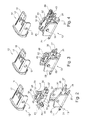
- the adapter element 13 on the wiper blade side has, on its underside facing toward the wiper rubber 23, a receptacle 26 by way of which the adapter element 13 on the wiper blade side, in the manner of a rider, encompasses and fixes the spring rails together with the wiper rubber 23. It is also possible to see washer fluid connectors 27 which engage into corresponding washer fluid ducts of an additional element connected to the adapter element 13 on the wiper blade side. Spray openings (not illustrated) formed on the two opposite longitudinal sides of the wiper blade body 22 and/or of the additional element open out into the said washer fluid ducts.
- the adapter element 13 on the wiper blade side has, proceeding from a base region 28, two plate-like side walls 29, 30 arranged parallel to one another. In the two side walls 29, 30 there is formed in each case one aperture 31, 32 of circular cross section, which aperture simultaneously defines or forms the axis 14.
- the distributor element 35 which serves for providing the hydraulic and electrical supply.
- the distributor element 35 has a first connection body 36 which serves for the hydraulic supply to the washer fluid connector 27, which connection body 36 has connection pieces 37, 38 which are in turn connected to the hose lines 18, 19.
- a hydraulic connection plug 39 arranged on the side situated opposite the connection pieces 37, 38 of the first connection body 36 can be connected to the base region 28 of the adapter element 13 on the wiper blade side, in order to form a hydraulic connection between the connection piece 37, 38 and the washer fluid connector 27.
- the first connection body 36 of the distributor element 25 is connected to a second connection body 42, which can be seen only in figures 4 and 6 .
- the second connection body 42 has two plug connections 43, 44 which are arranged parallel and above the connection piece 37, 38 and which in turn can be electrically contacted with the line 20.
- the second connection body 42 is connected to the first connection body 36 by means of a detent connection.
- the first connection body 36 has two detent tongues 46, 47 which project in the direction of the second connection body 42 and which interact with corresponding cutouts on the second connection body 42 and which, in the connecting position illustrated in figure 4 , form the said detent connection with the second connection body 42.
- the planar upper sides 48, 49 of the detent tongues 46, 47 form, together with the elevation 45, three contact surfaces which are arranged in abutting contact with the inner side of the wiper arm 1, such that the distributor element 35 is positioned and/or fixed with respect to the wiper arm 1.
- the spring tongue 17 and the actuating button 16 are arranged between the two detent tongues 46, 47.
- the second connection body 42 is received between side arms 51, 52 of the first connection body 36.
- the side arms 51, 52 are arranged so as to be resilient in the direction of the double arrows 53, 54.
- the side arms 51, 52 On the sides, which face away from one another, of the side arms 51, 52, the side arms 51, 52 have peg-like bearing extensions 55, 56 which are integrally formed thereon and which have a circular cross section.
- the bearing extensions 55, 56 extend through the apertures 31, 32 of the side walls 29, 30 of the adapter element 13 on the wiper blade side such that the bearing extensions 55, 56 project beyond the side walls 29, 30 of the adapter element 13 on the wiper blade side on the side facing away from the distributor element 35.
- bearing extensions 55, 56 which project beyond the side walls 29, 30 serve for the pivotable mounting of the adapter element 12 on the wiper arm side, for which purpose the latter has recesses which are formed in alignment with the bearing extensions 55, 56 and which are formed as through-openings 57, 58.
- the mounting of the wiper blade adapter 11 and of the distributor element 35 is, corresponding to figures 2 to 4 , as follows: Firstly, in a first step, by virtue of the two side arms 51, 52 being pressed together, the first connection body 36 is fastened to the adapter element 13 on the wiper arm side by virtue of the bearing extensions 55, 56 being arranged in the apertures 31, 32. Subsequently, corresponding to figure 4 (if this has not already taken place in a preceding manufacturing step, the second connection body 42 may be connected to the first connection body 36 by means of the said detent connection.
- the adapter element 12 on the wiper arm side is connected to the adapter element 13 on the wiper blade side by virtue of the through-openings 57, 58 in the side walls of the adapter element 12 on the wiper arm side being placed in operative connection with those portions of the bearing extensions 55, 56 which project out of the side walls 29, 30 of the adapter element 13 on the wiper blade side.
- the wiper blade adapter 11 pre-assembled in this way may for example subsequently be connected to the other parts of the wiper blade 10.
- the mounting of the wiper blade 10 on the wiper arm 1 takes place by pushing the wiper blade adapter 11 into the open (U-shaped) cross section of the wiper arm 1 in the connecting region, wherein the actuating button 16 forms the detent connection with the recess of the wiper arm 1.
- the wiper blade 10 is in the mounted state on the wiper arm 1, the region of the bearing extensions 55, 56 is covered by the side walls of the wiper arm 1.
- the wiper blade 10 thus described may be altered or modified in a variety of ways without departing from the concept of the invention.
- a single-piece distributor element 35 instead of a distributor element 35 composed of the two connection bodies 36, 42.
- It also falls within the scope of the invention, for example, to dispense with a heating device or a washer device.
- a distributor element 35 is provided which, by way of its bearing extensions 55, 56, serves for the mounting of the adapter element 12 on the wiper arm side.
Applications Claiming Priority (1)
| Application Number | Priority Date | Filing Date | Title |
|---|---|---|---|
| DE201210106946 DE102012106946A1 (de) | 2012-07-30 | 2012-07-30 | Wischblatt zum Reinigen von Fahrzeugscheiben |
Publications (3)
| Publication Number | Publication Date |
|---|---|
| EP2692596A2 true EP2692596A2 (de) | 2014-02-05 |
| EP2692596A3 EP2692596A3 (de) | 2017-12-20 |
| EP2692596B1 EP2692596B1 (de) | 2019-01-16 |
Family
ID=48874909
Family Applications (1)
| Application Number | Title | Priority Date | Filing Date |
|---|---|---|---|
| EP13178285.6A Active EP2692596B1 (de) | 2012-07-30 | 2013-07-26 | Wischerblatt zur Reinigung von Fahrzeugscheiben |
Country Status (3)
| Country | Link |
|---|---|
| US (1) | US9126569B2 (de) |
| EP (1) | EP2692596B1 (de) |
| DE (1) | DE102012106946A1 (de) |
Cited By (1)
| Publication number | Priority date | Publication date | Assignee | Title |
|---|---|---|---|---|
| WO2017108616A1 (de) * | 2015-12-22 | 2017-06-29 | Robert Bosch Gmbh | Wischervorrichtung |
Citations (1)
| Publication number | Priority date | Publication date | Assignee | Title |
|---|---|---|---|---|
| DE102010025687A1 (de) | 2010-06-30 | 2012-01-05 | Valeo Wischersysteme Gmbh | Wischblatt zum Reinigen von Fahrzeugscheiben |
Family Cites Families (5)
| Publication number | Priority date | Publication date | Assignee | Title |
|---|---|---|---|---|
| US2798244A (en) * | 1954-08-20 | 1957-07-09 | Max Zaiger | Arm and blade connector for windshield wipers |
| DE10028628A1 (de) * | 2000-06-09 | 2001-12-13 | Bosch Gmbh Robert | Scheibenwischer für Kraftfahrzeuge |
| JP4580124B2 (ja) * | 2001-07-11 | 2010-11-10 | アスモ株式会社 | ワイパアーム |
| DE102008049269B4 (de) * | 2008-09-26 | 2020-08-27 | Valeo Systèmes d'Essuyage | Wischarm/Wischblatt-Verbindung sowie Wischblatt |
| FR2964620B1 (fr) * | 2010-09-09 | 2014-01-31 | Valeo Systemes Dessuyage | Connecteur hydraulique supportant un axe de rotation d'un systeme d'essuyage |
-
2012
- 2012-07-30 DE DE201210106946 patent/DE102012106946A1/de not_active Withdrawn
-
2013
- 2013-07-26 EP EP13178285.6A patent/EP2692596B1/de active Active
- 2013-07-30 US US13/953,994 patent/US9126569B2/en not_active Expired - Fee Related
Patent Citations (1)
| Publication number | Priority date | Publication date | Assignee | Title |
|---|---|---|---|---|
| DE102010025687A1 (de) | 2010-06-30 | 2012-01-05 | Valeo Wischersysteme Gmbh | Wischblatt zum Reinigen von Fahrzeugscheiben |
Cited By (2)
| Publication number | Priority date | Publication date | Assignee | Title |
|---|---|---|---|---|
| WO2017108616A1 (de) * | 2015-12-22 | 2017-06-29 | Robert Bosch Gmbh | Wischervorrichtung |
| US11305736B2 (en) | 2015-12-22 | 2022-04-19 | Robert Bosch Gmbh | Wiper device |
Also Published As
| Publication number | Publication date |
|---|---|
| EP2692596A3 (de) | 2017-12-20 |
| US9126569B2 (en) | 2015-09-08 |
| DE102012106946A1 (de) | 2014-05-15 |
| EP2692596B1 (de) | 2019-01-16 |
| US20140026347A1 (en) | 2014-01-30 |
Similar Documents
| Publication | Publication Date | Title |
|---|---|---|
| EP2692595B1 (de) | Wischblatt zum Reinigen von Fahrzeugscheiben | |
| US8935825B2 (en) | Wiper blade assembly | |
| KR100688047B1 (ko) | 차량의 윈도우용 와이퍼 장치 | |
| CN106627499B (zh) | 用于风挡雨刮器刷的连接系统的元件 | |
| EP2813403B1 (de) | Wischsystem | |
| US11345316B2 (en) | Windscreen wiper device | |
| CN107054301B (zh) | 用于机动车辆风挡擦拭器的适配器 | |
| MXPA06002308A (es) | Un brazo para limpiador de parabrisas. | |
| US10611342B2 (en) | Windshield wiper assembly | |
| CN105452069A (zh) | 刮水片以及刮水器 | |
| CN101925495A (zh) | 用于机动车风挡擦拭器刮片的连接平台 | |
| JP2013530085A (ja) | 電気コンタクトを有する風防ガラスワイパアダプタ | |
| EP2697100A1 (de) | Scheibenwischervorrichtung | |
| US20220161764A1 (en) | Wiper blade, in particular for a motor vehicle | |
| CN103228501B (zh) | 刮水装置 | |
| EP2692596B1 (de) | Wischerblatt zur Reinigung von Fahrzeugscheiben | |
| CN107031573B (zh) | 用于将风挡擦拭器叶片保持器连接到驱动臂的系统的元件 | |
| US20120117747A1 (en) | Pivot body for windshield wiper system | |
| EP2815932B1 (de) | Wischerblatt zum Reinigen von Fahrzeugscheiben, Wischerarm für ein Wischerblatt und Wischervorrichtung | |
| EP2864162B1 (de) | Scheibenwischervorrichtung | |
| EP2621772A1 (de) | Scheibenwischervorrichtung | |
| US11577699B2 (en) | Windscreen wiper device | |
| JP2014504572A (ja) | フロントガラス用ワイパー装置 | |
| KR20120025410A (ko) | 전력반도체 모듈용 접속장치 | |
| CN108883745B (zh) | 雨刮臂装置 |
Legal Events
| Date | Code | Title | Description |
|---|---|---|---|
| 17P | Request for examination filed |
Effective date: 20130726 |
|
| AK | Designated contracting states |
Kind code of ref document: A2 Designated state(s): AL AT BE BG CH CY CZ DE DK EE ES FI FR GB GR HR HU IE IS IT LI LT LU LV MC MK MT NL NO PL PT RO RS SE SI SK SM TR |
|
| AX | Request for extension of the european patent |
Extension state: BA ME |
|
| PUAI | Public reference made under article 153(3) epc to a published international application that has entered the european phase |
Free format text: ORIGINAL CODE: 0009012 |
|
| PUAL | Search report despatched |
Free format text: ORIGINAL CODE: 0009013 |
|
| AK | Designated contracting states |
Kind code of ref document: A3 Designated state(s): AL AT BE BG CH CY CZ DE DK EE ES FI FR GB GR HR HU IE IS IT LI LT LU LV MC MK MT NL NO PL PT RO RS SE SI SK SM TR |
|
| AX | Request for extension of the european patent |
Extension state: BA ME |
|
| RIC1 | Information provided on ipc code assigned before grant |
Ipc: B60S 1/38 20060101AFI20171113BHEP |
|
| GRAP | Despatch of communication of intention to grant a patent |
Free format text: ORIGINAL CODE: EPIDOSNIGR1 |
|
| STAA | Information on the status of an ep patent application or granted ep patent |
Free format text: STATUS: GRANT OF PATENT IS INTENDED |
|
| INTG | Intention to grant announced |
Effective date: 20180809 |
|
| GRAS | Grant fee paid |
Free format text: ORIGINAL CODE: EPIDOSNIGR3 |
|
| GRAA | (expected) grant |
Free format text: ORIGINAL CODE: 0009210 |
|
| STAA | Information on the status of an ep patent application or granted ep patent |
Free format text: STATUS: THE PATENT HAS BEEN GRANTED |
|
| AK | Designated contracting states |
Kind code of ref document: B1 Designated state(s): AL AT BE BG CH CY CZ DE DK EE ES FI FR GB GR HR HU IE IS IT LI LT LU LV MC MK MT NL NO PL PT RO RS SE SI SK SM TR |
|
| REG | Reference to a national code |
Ref country code: GB Ref legal event code: FG4D |
|
| REG | Reference to a national code |
Ref country code: CH Ref legal event code: EP |
|
| REG | Reference to a national code |
Ref country code: IE Ref legal event code: FG4D |
|
| REG | Reference to a national code |
Ref country code: DE Ref legal event code: R096 Ref document number: 602013049811 Country of ref document: DE |
|
| REG | Reference to a national code |
Ref country code: AT Ref legal event code: REF Ref document number: 1089486 Country of ref document: AT Kind code of ref document: T Effective date: 20190215 |
|
| REG | Reference to a national code |
Ref country code: NL Ref legal event code: MP Effective date: 20190116 |
|
| REG | Reference to a national code |
Ref country code: LT Ref legal event code: MG4D |
|
| PG25 | Lapsed in a contracting state [announced via postgrant information from national office to epo] |
Ref country code: NL Free format text: LAPSE BECAUSE OF FAILURE TO SUBMIT A TRANSLATION OF THE DESCRIPTION OR TO PAY THE FEE WITHIN THE PRESCRIBED TIME-LIMIT Effective date: 20190116 |
|
| REG | Reference to a national code |
Ref country code: AT Ref legal event code: MK05 Ref document number: 1089486 Country of ref document: AT Kind code of ref document: T Effective date: 20190116 |
|
| PG25 | Lapsed in a contracting state [announced via postgrant information from national office to epo] |
Ref country code: SE Free format text: LAPSE BECAUSE OF FAILURE TO SUBMIT A TRANSLATION OF THE DESCRIPTION OR TO PAY THE FEE WITHIN THE PRESCRIBED TIME-LIMIT Effective date: 20190116 Ref country code: PT Free format text: LAPSE BECAUSE OF FAILURE TO SUBMIT A TRANSLATION OF THE DESCRIPTION OR TO PAY THE FEE WITHIN THE PRESCRIBED TIME-LIMIT Effective date: 20190516 Ref country code: PL Free format text: LAPSE BECAUSE OF FAILURE TO SUBMIT A TRANSLATION OF THE DESCRIPTION OR TO PAY THE FEE WITHIN THE PRESCRIBED TIME-LIMIT Effective date: 20190116 Ref country code: LT Free format text: LAPSE BECAUSE OF FAILURE TO SUBMIT A TRANSLATION OF THE DESCRIPTION OR TO PAY THE FEE WITHIN THE PRESCRIBED TIME-LIMIT Effective date: 20190116 Ref country code: ES Free format text: LAPSE BECAUSE OF FAILURE TO SUBMIT A TRANSLATION OF THE DESCRIPTION OR TO PAY THE FEE WITHIN THE PRESCRIBED TIME-LIMIT Effective date: 20190116 Ref country code: NO Free format text: LAPSE BECAUSE OF FAILURE TO SUBMIT A TRANSLATION OF THE DESCRIPTION OR TO PAY THE FEE WITHIN THE PRESCRIBED TIME-LIMIT Effective date: 20190416 Ref country code: FI Free format text: LAPSE BECAUSE OF FAILURE TO SUBMIT A TRANSLATION OF THE DESCRIPTION OR TO PAY THE FEE WITHIN THE PRESCRIBED TIME-LIMIT Effective date: 20190116 |
|
| PG25 | Lapsed in a contracting state [announced via postgrant information from national office to epo] |
Ref country code: IS Free format text: LAPSE BECAUSE OF FAILURE TO SUBMIT A TRANSLATION OF THE DESCRIPTION OR TO PAY THE FEE WITHIN THE PRESCRIBED TIME-LIMIT Effective date: 20190516 Ref country code: BG Free format text: LAPSE BECAUSE OF FAILURE TO SUBMIT A TRANSLATION OF THE DESCRIPTION OR TO PAY THE FEE WITHIN THE PRESCRIBED TIME-LIMIT Effective date: 20190416 Ref country code: RS Free format text: LAPSE BECAUSE OF FAILURE TO SUBMIT A TRANSLATION OF THE DESCRIPTION OR TO PAY THE FEE WITHIN THE PRESCRIBED TIME-LIMIT Effective date: 20190116 Ref country code: HR Free format text: LAPSE BECAUSE OF FAILURE TO SUBMIT A TRANSLATION OF THE DESCRIPTION OR TO PAY THE FEE WITHIN THE PRESCRIBED TIME-LIMIT Effective date: 20190116 Ref country code: LV Free format text: LAPSE BECAUSE OF FAILURE TO SUBMIT A TRANSLATION OF THE DESCRIPTION OR TO PAY THE FEE WITHIN THE PRESCRIBED TIME-LIMIT Effective date: 20190116 Ref country code: GR Free format text: LAPSE BECAUSE OF FAILURE TO SUBMIT A TRANSLATION OF THE DESCRIPTION OR TO PAY THE FEE WITHIN THE PRESCRIBED TIME-LIMIT Effective date: 20190417 |
|
| REG | Reference to a national code |
Ref country code: DE Ref legal event code: R097 Ref document number: 602013049811 Country of ref document: DE |
|
| PG25 | Lapsed in a contracting state [announced via postgrant information from national office to epo] |
Ref country code: CZ Free format text: LAPSE BECAUSE OF FAILURE TO SUBMIT A TRANSLATION OF THE DESCRIPTION OR TO PAY THE FEE WITHIN THE PRESCRIBED TIME-LIMIT Effective date: 20190116 Ref country code: SK Free format text: LAPSE BECAUSE OF FAILURE TO SUBMIT A TRANSLATION OF THE DESCRIPTION OR TO PAY THE FEE WITHIN THE PRESCRIBED TIME-LIMIT Effective date: 20190116 Ref country code: AL Free format text: LAPSE BECAUSE OF FAILURE TO SUBMIT A TRANSLATION OF THE DESCRIPTION OR TO PAY THE FEE WITHIN THE PRESCRIBED TIME-LIMIT Effective date: 20190116 Ref country code: EE Free format text: LAPSE BECAUSE OF FAILURE TO SUBMIT A TRANSLATION OF THE DESCRIPTION OR TO PAY THE FEE WITHIN THE PRESCRIBED TIME-LIMIT Effective date: 20190116 Ref country code: DK Free format text: LAPSE BECAUSE OF FAILURE TO SUBMIT A TRANSLATION OF THE DESCRIPTION OR TO PAY THE FEE WITHIN THE PRESCRIBED TIME-LIMIT Effective date: 20190116 Ref country code: RO Free format text: LAPSE BECAUSE OF FAILURE TO SUBMIT A TRANSLATION OF THE DESCRIPTION OR TO PAY THE FEE WITHIN THE PRESCRIBED TIME-LIMIT Effective date: 20190116 Ref country code: IT Free format text: LAPSE BECAUSE OF FAILURE TO SUBMIT A TRANSLATION OF THE DESCRIPTION OR TO PAY THE FEE WITHIN THE PRESCRIBED TIME-LIMIT Effective date: 20190116 Ref country code: AT Free format text: LAPSE BECAUSE OF FAILURE TO SUBMIT A TRANSLATION OF THE DESCRIPTION OR TO PAY THE FEE WITHIN THE PRESCRIBED TIME-LIMIT Effective date: 20190116 |
|
| PLBE | No opposition filed within time limit |
Free format text: ORIGINAL CODE: 0009261 |
|
| STAA | Information on the status of an ep patent application or granted ep patent |
Free format text: STATUS: NO OPPOSITION FILED WITHIN TIME LIMIT |
|
| PG25 | Lapsed in a contracting state [announced via postgrant information from national office to epo] |
Ref country code: SM Free format text: LAPSE BECAUSE OF FAILURE TO SUBMIT A TRANSLATION OF THE DESCRIPTION OR TO PAY THE FEE WITHIN THE PRESCRIBED TIME-LIMIT Effective date: 20190116 |
|
| 26N | No opposition filed |
Effective date: 20191017 |
|
| PG25 | Lapsed in a contracting state [announced via postgrant information from national office to epo] |
Ref country code: SI Free format text: LAPSE BECAUSE OF FAILURE TO SUBMIT A TRANSLATION OF THE DESCRIPTION OR TO PAY THE FEE WITHIN THE PRESCRIBED TIME-LIMIT Effective date: 20190116 Ref country code: MC Free format text: LAPSE BECAUSE OF FAILURE TO SUBMIT A TRANSLATION OF THE DESCRIPTION OR TO PAY THE FEE WITHIN THE PRESCRIBED TIME-LIMIT Effective date: 20190116 |
|
| REG | Reference to a national code |
Ref country code: CH Ref legal event code: PL |
|
| GBPC | Gb: european patent ceased through non-payment of renewal fee |
Effective date: 20190726 |
|
| PG25 | Lapsed in a contracting state [announced via postgrant information from national office to epo] |
Ref country code: TR Free format text: LAPSE BECAUSE OF FAILURE TO SUBMIT A TRANSLATION OF THE DESCRIPTION OR TO PAY THE FEE WITHIN THE PRESCRIBED TIME-LIMIT Effective date: 20190116 |
|
| REG | Reference to a national code |
Ref country code: BE Ref legal event code: MM Effective date: 20190731 |
|
| PG25 | Lapsed in a contracting state [announced via postgrant information from national office to epo] |
Ref country code: GB Free format text: LAPSE BECAUSE OF NON-PAYMENT OF DUE FEES Effective date: 20190726 |
|
| PG25 | Lapsed in a contracting state [announced via postgrant information from national office to epo] |
Ref country code: BE Free format text: LAPSE BECAUSE OF NON-PAYMENT OF DUE FEES Effective date: 20190731 Ref country code: LU Free format text: LAPSE BECAUSE OF NON-PAYMENT OF DUE FEES Effective date: 20190726 Ref country code: LI Free format text: LAPSE BECAUSE OF NON-PAYMENT OF DUE FEES Effective date: 20190731 Ref country code: CH Free format text: LAPSE BECAUSE OF NON-PAYMENT OF DUE FEES Effective date: 20190731 |
|
| PG25 | Lapsed in a contracting state [announced via postgrant information from national office to epo] |
Ref country code: FR Free format text: LAPSE BECAUSE OF NON-PAYMENT OF DUE FEES Effective date: 20190731 |
|
| PG25 | Lapsed in a contracting state [announced via postgrant information from national office to epo] |
Ref country code: IE Free format text: LAPSE BECAUSE OF NON-PAYMENT OF DUE FEES Effective date: 20190726 |
|
| PG25 | Lapsed in a contracting state [announced via postgrant information from national office to epo] |
Ref country code: CY Free format text: LAPSE BECAUSE OF FAILURE TO SUBMIT A TRANSLATION OF THE DESCRIPTION OR TO PAY THE FEE WITHIN THE PRESCRIBED TIME-LIMIT Effective date: 20190116 |
|
| PG25 | Lapsed in a contracting state [announced via postgrant information from national office to epo] |
Ref country code: HU Free format text: LAPSE BECAUSE OF FAILURE TO SUBMIT A TRANSLATION OF THE DESCRIPTION OR TO PAY THE FEE WITHIN THE PRESCRIBED TIME-LIMIT; INVALID AB INITIO Effective date: 20130726 Ref country code: MT Free format text: LAPSE BECAUSE OF FAILURE TO SUBMIT A TRANSLATION OF THE DESCRIPTION OR TO PAY THE FEE WITHIN THE PRESCRIBED TIME-LIMIT Effective date: 20190116 |
|
| PG25 | Lapsed in a contracting state [announced via postgrant information from national office to epo] |
Ref country code: MK Free format text: LAPSE BECAUSE OF FAILURE TO SUBMIT A TRANSLATION OF THE DESCRIPTION OR TO PAY THE FEE WITHIN THE PRESCRIBED TIME-LIMIT Effective date: 20190116 |
|
| P01 | Opt-out of the competence of the unified patent court (upc) registered |
Effective date: 20230528 |
|
| PGFP | Annual fee paid to national office [announced via postgrant information from national office to epo] |
Ref country code: DE Payment date: 20230712 Year of fee payment: 11 |