EP2692579A1 - Seat cushion and vehicle seat - Google Patents
Seat cushion and vehicle seat Download PDFInfo
- Publication number
- EP2692579A1 EP2692579A1 EP12764185.0A EP12764185A EP2692579A1 EP 2692579 A1 EP2692579 A1 EP 2692579A1 EP 12764185 A EP12764185 A EP 12764185A EP 2692579 A1 EP2692579 A1 EP 2692579A1
- Authority
- EP
- European Patent Office
- Prior art keywords
- seat
- seat cushion
- elastic member
- occupant
- cushion
- Prior art date
- Legal status (The legal status is an assumption and is not a legal conclusion. Google has not performed a legal analysis and makes no representation as to the accuracy of the status listed.)
- Withdrawn
Links
Images



Classifications
-
- B—PERFORMING OPERATIONS; TRANSPORTING
- B60—VEHICLES IN GENERAL
- B60N—SEATS SPECIALLY ADAPTED FOR VEHICLES; VEHICLE PASSENGER ACCOMMODATION NOT OTHERWISE PROVIDED FOR
- B60N2/00—Seats specially adapted for vehicles; Arrangement or mounting of seats in vehicles
- B60N2/68—Seat frames
- B60N2/682—Joining means
-
- B—PERFORMING OPERATIONS; TRANSPORTING
- B60—VEHICLES IN GENERAL
- B60N—SEATS SPECIALLY ADAPTED FOR VEHICLES; VEHICLE PASSENGER ACCOMMODATION NOT OTHERWISE PROVIDED FOR
- B60N2/00—Seats specially adapted for vehicles; Arrangement or mounting of seats in vehicles
- B60N2/70—Upholstery springs ; Upholstery
- B60N2/7094—Upholstery springs
-
- B—PERFORMING OPERATIONS; TRANSPORTING
- B60—VEHICLES IN GENERAL
- B60N—SEATS SPECIALLY ADAPTED FOR VEHICLES; VEHICLE PASSENGER ACCOMMODATION NOT OTHERWISE PROVIDED FOR
- B60N2/00—Seats specially adapted for vehicles; Arrangement or mounting of seats in vehicles
- B60N2/64—Back-rests or cushions
-
- B—PERFORMING OPERATIONS; TRANSPORTING
- B60—VEHICLES IN GENERAL
- B60N—SEATS SPECIALLY ADAPTED FOR VEHICLES; VEHICLE PASSENGER ACCOMMODATION NOT OTHERWISE PROVIDED FOR
- B60N2/00—Seats specially adapted for vehicles; Arrangement or mounting of seats in vehicles
- B60N2/64—Back-rests or cushions
- B60N2/646—Back-rests or cushions shape of the cushion
-
- B—PERFORMING OPERATIONS; TRANSPORTING
- B60—VEHICLES IN GENERAL
- B60N—SEATS SPECIALLY ADAPTED FOR VEHICLES; VEHICLE PASSENGER ACCOMMODATION NOT OTHERWISE PROVIDED FOR
- B60N2/00—Seats specially adapted for vehicles; Arrangement or mounting of seats in vehicles
- B60N2/68—Seat frames
- B60N2/686—Panel like structures
-
- B—PERFORMING OPERATIONS; TRANSPORTING
- B60—VEHICLES IN GENERAL
- B60N—SEATS SPECIALLY ADAPTED FOR VEHICLES; VEHICLE PASSENGER ACCOMMODATION NOT OTHERWISE PROVIDED FOR
- B60N2/00—Seats specially adapted for vehicles; Arrangement or mounting of seats in vehicles
- B60N2/70—Upholstery springs ; Upholstery
- B60N2/72—Attachment or adjustment thereof
Definitions
- the present invention relates to a seat cushion and a vehicle seat, and particularly, to a seat cushion and a vehicle seat that easily follow a human body of an occupant, have satisfactory vibration characteristics, and provide an excellent sitting comfort.
- a seat portion supporting buttocks and thighs of an occupant is provided in a manner that a cushion pad is placed on a seat base frame and is covered with a skin material (trim cover).
- a skin material titanium cover
- the following capability (fit comfort) of the seat cushion with respect to the occupant or the vibration characteristics in the vehicle running state may be exemplified.
- the vibration characteristics may easily influence the occupant sitting on the seat cushion for a long period of time.
- a vibration is generated from a floor surface in a vehicle running state.
- the vibration generated at this time is transmitted to the vehicle seat, the seat cushion is vibrated at a low frequency (about 3 to 4 Hz).
- a low frequency about 3 to 4 Hz.
- a technique which reduces a vibration transmitted from a vehicle body and reduces a resonance.
- a seat cushion may be exemplified in which a pan frame is provided and a plurality of S-shaped springs are installed at positions corresponding to the buttocks of the occupant in the pan frame.
- a satisfactory cushion property may be obtained by the elastic deformation of the S-shaped springs and the cushion pad. As a result, it is possible to reduce the vibration transmitted from the vehicle body in the vehicle running state.
- Patent Document 1 discloses a seat cushion which further reduces a vibration.
- a seat cushion is disclosed in which a recessed buttocks receiving portion (air room) is formed in a pan frame at a position corresponding to the buttocks of the occupant.
- the air room is a space which is formed between the pan frame and a cushion pad (described as a "seat pad” in Patent Document 1) placed on the pan frame, and an orifice communicating with the air room is formed in a wall surface of the pan frame.
- Patent Document 2 a technique of reducing a sitting pressure at a specific position influencing a sitting comfort is disclosed in Patent Document 2.
- a hole or a concave portion is formed directly below an ischial tuberosity of an occupant in a pan frame so as to decrease the pressure directly below the ischial tuberosity (the pressure of the portion with the highest sitting pressure).
- the cushion pad may easily follow the human body of the occupant. Then, since the S-shaped springs are installed above the air room, the vibration may be reduced without separately providing the suspension device or the like.
- the pan frame as the seat base frame is provided in the entire surface of the seat base frame, and the pan frame needs to be disposed to the portion corresponding to not only the thighs of the occupant but also the buttocks thereof.
- the weight is large. Accordingly, it is desirable to devise a seat cushion which further improves a sitting comfort by a simple and light-weight configuration of the seat cushion and high following capability to an occupant.
- Patent Document 2 since the cushion pad (described as a "cushion member” in Patent Document 2) is placed on the pan frame provided with the hole or the concave portion, the sitting pressure (the ischial pressure) is reduced. However, since the upward biasing force is not exerted when the cushion pad is deflected by the load of the occupant, a problem arises that the following capability to the human body of the occupant is not satisfactory.
- a technique which provides a seat cushion that has high following capability to a human body of an occupant (that is, a satisfactory fit comfort), has a low sitting ischial pressure, and has a satisfactory sitting comfort.
- a seat cushion including: a seat base frame; a cushion pad which is placed on the seat base frame; and a skin material which covers the seat base frame and the cushion pad, in which the seat base frame includes a pair of side frames that extends in the front to back direction, a front elastic member that is installed in the pair of side frames and is in contact with the cushion pad, and a rear elastic member that is disposed while being separated from the front elastic member by a predetermined distance and is in contact with the cushion pad, in which a pad contact surface of the front elastic member is disposed to be inclined rearward with respect to a horizontal plane, and in which a pad contact surface of the rear elastic member is disposed to be inclined forward with respect to the horizontal plane or to be parallel thereto.
- the seat cushion of the present invention two elastic members are provided to be laid across the side frames. Then, the elastic members (the front elastic member and the rear elastic member) provided at two positions support the cushion pad placed on the seat base frame. At this time, the pad contact surface (that is, the upper surface of the front elastic member) of the front elastic member is disposed to be inclined rearward with respect to the horizontal plane (the rear side of the pad contact surface is inclined downward). Further, the pad contact surface (that is, the upper surface of the rear elastic member) of the rear elastic member is disposed to be inclined forward with respect to the horizontal plane (the front side of the pad contact surface is inclined downward) or to be horizontal.
- the buttocks of the occupant since the buttocks of the occupant is curved and bulge downward, the buttocks push the cushion pad downward while deflecting the cushion pad downward during the sitting operation. At this time, in the contact surface of the cushion pad with respect to the buttocks of the occupant, the front and rear sides of the buttocks are inclined upward.
- the seat cushion of the present invention when the occupant sits on the seat cushion, the upward biasing force is exerted on the cushion pad by the front elastic member inclined rearward and the rear elastic member inclined forward, and hence the cushion pad easily follows the buttocks of the occupant. Accordingly, a satisfactory sitting comfort may be obtained.
- the seat cushion of the present invention may provide a satisfactory sitting comfort for the occupant by reducing the ischial pressure.
- the light-weight elastic member is used as the configuration in which the cushion pad follows the buttocks of the occupant without using a large pan frame, the weight of the seat cushion does not increase.
- the cushion pad may easily follow the buttocks of the occupant.
- the cushion pad may further easily follow the buttocks of the occupant in consideration of the deflection amount of the cushion pad.
- the ⁇ 1 may be in the range of 17 to 21°
- the ⁇ 2 may be in the range of 0 to 3°.
- the cushion pad may easily follow the buttocks of the occupant and the occupant does not feel any difference in height by the elastic member or does not feel the sense of hitting the bottom surface. Further, when ⁇ 2 is set to the above-described value, the thickness of the cushion pad may be ensured without decreasing the thickness of the cushion pad too much compared to the case where ⁇ 2 is set to be larger than the above-described value, and hence the more satisfactory sitting comfort may be provided for the occupant.
- the seat base frame may further include a plate-shaped frame installed in the pair of side frames, and the plate-shaped frame may be disposed in front of the front elastic member.
- the seat base frame further includes the plate-shaped frame and the plate-shaped frame is disposed in front of the front elastic member, the thighs of the occupant may be supported. Accordingly, in the seat cushion with the above-described configuration, the occupant contact portion (the buttocks and the thigh) may be reliably supported and the satisfactory sitting comfort may be obtained. Further, since the plate-shaped frame is provided only in the portion corresponding to the thigh, the weight of the seat cushion does not increase too much.
- a rear end of the plate-shaped frame may be provided to satisfy a relation of 0.73 ⁇ ⁇ / ⁇ ⁇ 1.09 when a height from the rear end to a hip point of a three-dimensional mannequin based on SAE J-826 is denoted by ⁇ , a distance from the rear end to the hip point in the front to back direction is denoted by ⁇ , and a ratio between the ⁇ and the ⁇ is denoted by ⁇ / ⁇ .
- the seat cushion of the present invention may have an extremely light weight compared to the seat cushion in which the pan frame is used in the entire surface of the seat base frame and the pan frame is provided from the position of the thighs of the occupant to the buttocks thereof.
- the weight of the seat base frame may be decreased, but the range in which the pan frame supports the occupant is not sufficient. As a result, there is a concern that the vibration characteristics may be degraded.
- the rear end of the pan frame is disposed at the above-described position, and hence a seat cushion having a satisfactory vibration characteristic and a light weight may be provided.
- the position of the rear end of the pan frame is set as described above. Accordingly, the resonance magnification with respect to the vibration transmitted from the vehicle is reduced compared to the seat cushion in which the pan frame does not have the above-described configuration, and hence the resonance frequency further increases. As a result, since the resonance frequency of the seat cushion is shifted from the resonance zone of the human body of the occupant, the vibration of the vehicle is not easily transmitted to the occupant. Accordingly, the seat cushion of the present invention may be decreased in weight and improve the vibration characteristics. Thus, a satisfactory sitting comfort may be provided for the occupant.
- the ⁇ may be in the range of 85 to 105 mm, and the ⁇ may be in the range of 96 to 116 mm.
- a vehicle seat including any one of the above-described seat cushions and a seatback.
- the vehicle seat of the present invention has the above-described light-weight and simple configuration, and includes the seat cushion which provides a satisfactory sitting comfort. Accordingly, the vehicle seat may be provided which has a light weight as a whole and has a satisfactory sitting comfort.
- the seat cushion since the light-weight elastic member biases the cushion pad upward with a predetermined angle, the seat cushion may be provided which causes the cushion pad to easily follow the buttocks of the occupant with a simple and light-weight configuration and obtains a satisfactory sitting comfort. Further, since the front elastic member and the rear elastic member are disposed while being separated from each other in the front to back direction, the ischial pressure may be reduced, and hence the seat cushion with a satisfactory sitting comfort may be provided.
- the cushion pad may further easily follow the buttocks of the occupant. Accordingly, the seat cushion with a satisfactory sitting comfort may be provided.
- the cushion pad since the elastic members are disposed considering the deflection of the cushion pad, the cushion pad may further easily follow the buttocks of the occupant, and hence the sitting comfort may be improved.
- the seat cushion with a satisfactory sitting comfort may be provided. Further, the satisfactory sitting comfort may be provided for the occupant without thinning the cushion pad even when the cushion pad is disposed at the rear side of the seat cushion.
- the thighs may be also reliably supported when the occupant sits on the seat cushion, the sitting comfort is further improved. Further, since the plate-shaped frame is provided only in the portion corresponding to the thigh, the seat cushion may be provided which has a satisfactory sitting comfort and a light weight.
- the vehicle seat since the seat cushion has a light-weight and simple configuration and has a satisfactory sitting comfort, the vehicle seat may be provided which has a light weight and a satisfactory sitting comfort.
- the vibration characteristics are satisfactory, and hence the seat cushion may be provided which obtains a satisfactory sitting comfort.
- a vehicle indicates a ground running conveyance such as an automobile and a train with wheels and a conveyance such as an airplane and a ship moving in a place other than a ground. That is, the vehicle indicates a conveyance to which a seat is attachable.
- a normal sitting load includes a sitting impact generated by a sitting operation and an acceleration load generated by a sudden starting operation of a conveyance.
- the terms representing the directions in the present specification are defined as the respective directions of Fig. 1 . That is, the right and left direction indicates the width direction of the vehicle seat, the left side when viewed from the sitting occupant indicates the left direction, and the right side when viewed from the sitting occupant indicates the right direction. Further, the front direction indicates the front side when viewed from the sitting occupant, and the back direction indicates the rear side when viewed from the sitting occupant.
- the "hip point” and the “H point” indicate the rotation center point that connects a torso and each thigh of a three-dimensional mannequin based on US-SAE standard J-826 (SAE-3 DM manufactured by ITOU SEIKI). Further, the "ischial tuberosity” indicates a portion which is located at the lowermost side of a pelvis of an occupant.
- Figs. 1 to 5 relate to an embodiment of the present invention, in which Fig. 1 is a schematic perspective view illustrating a vehicle seat, Fig. 2 is a schematic perspective view illustrating a seat base frame, Fig. 3 is an explanatory diagram illustrating a state where an occupant sits on a seat cushion, Fig. 4 is an explanatory diagram illustrating a configuration of an elastic member, and Fig. 5 is an explanatory diagram illustrating a configuration of a plate-shaped frame.
- Figs. 6 to 9 relate to seat cushions according to Example and Comparative Example of the present invention, in which Fig. 6 is a graph illustrating a sitting shape, Fig. 7 is a graph illustrating magnitudes of ischial pressures, Fig. 8 is a graph illustrating resonance magnifications, and Fig. 9 is a graph illustrating load characteristics.
- a vehicle seat S according to an embodiment will be described.
- the vehicle seat S includes a seatback S1 (back portion), a seat cushion S2, and a headrest S3, and the seatback S1 and the seat cushion S2 are formed in a manner that cushion pads 1a and 2a are placed on seat frames and are covered with skin materials 1b and 2b.
- the headrest S3 is formed in a manner that a pad material 3a is disposed on a head core (not illustrated) and is covered with a skin material 3b.
- the reference numeral 20 indicates a headrest pillar which supports the headrest S3.
- the seat frame of the vehicle seat S includes a seat back frame (not illustrated) which forms the seatback S1 and a seat base frame F which forms the seat cushion S2.
- the seatback S1 is formed in a manner that the cushion pad 1a is placed on the seat back frame and is covered with the skin material 1b from the upside of the cushion pad 1a, and is used to support a back of an occupant C from the rear side.
- the seat cushion S2 is formed in a manner that the cushion pad 2a is placed on the seat base frame F and is covered with the skin material 2b from the upside of the cushion pad 2a, and is used to support the occupant C from the downside.
- the seat base frame F is supported by leg portions (not illustrated), and inner rails are attached to the leg portions, so that the position of the seat base frame may be adjusted in a slidable manner in the front to back direction by the sliding movement between the inner rails and outer rails provided in a vehicle body floor.
- the rear end of the seat base frame F is connected to a seat back frame (not illustrated) through a reclining mechanism (not illustrated).
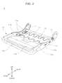
- the seat base frame F is substantially formed in a rectangular shape as illustrated in Fig. 2 , and includes side frames 11 and 11 which are separated from each other in the right and left direction, a pan frame 12 which serves as a plate-shaped frame installed at the front side (the front ends) of the side frames 11 and 11, a member pipe 13 which serves as a connection member disposed at the rear side of the side frames 11 and 11, a front spring 14 which serves as a front elastic member installed in the side frames 11 and 11, and a rear spring 15 which serves as a rear elastic member.
- pan frame 12 and the member pipe 13 are both installed in the side frames 11 and 11, and connect the side frames 11 and 11 to each other.
- the side frames are disposed while being separated from each other in the right and left direction and are disposed to extend in the front to back direction. Further, the member pipe 13 is attached to the rear side of the pair of side frames 11 and 11, and the pair of side frames 11 and 11 is connected to each other by the member pipe 13.
- pan frame 12 is fixed and joined to the front side of the pair of side frames 11 and 11, and the pair of side frames 11 and 11 is connected to each other even by the pan frame 12. More specifically, the ends of the pan frame 12 in the right and left direction are respectively fixed to flanges 11b and 11b respectively provided in the side frames 11 and 11.
- the pan frame 12 is a metallic frame of which the upper surface is substantially formed in a flat rectangular shape so as to mainly support the thighs of the occupant C. Furthermore, as illustrated in Fig. 2 , the upper surface of the pan frame 12 may be provided with a convex portion 12d which prevents a submarine phenomenon generated by the rear collision or a positional deviation during the sitting operation.
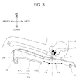
- the pan frame 12 includes a front bent portion 12a of which a front end is bent downward and a rear bent portion 12b of which a rear end is bent downward. Further, a support surface 12c of which an upper surface is substantially flat and is slightly inclined downward in the back direction is provided between the front bent portion 12a and the rear bent portion 12b. Furthermore, the ends of the support surface 12c in the right and left direction are respectively fixed to the flanges 11b and 11b of the side frames 11 and 11 (see Fig. 2 ).
- the end of the skin material 2b is locked to the end (the lower end) of the front bent portion 12a of the pan frame 12. Furthermore, as a method of locking the skin material 2b and the front bent portion 12a to each other, an existing method such as a trim cord is used.
- the front spring 14 and the rear spring 15 are disposed at the rear side in relation to the rear bent portion 12b of the pan frame 12.
- the front spring 14 and the rear spring 15 are laid across the side frames 11 and 11, and both ends of the front spring 14 and the rear spring 15 are respectively locked to lock portions 11c and 11c provided in the side frames 11 and 11.
- the lock portion 11c is provided in the side frame 11, two holes are formed while being separated from each other in the front to back direction, and a portion interposed between the holes bulges toward the inside of the side frame 11. Then, the end of the front spring 14 or the rear spring 15 is inserted from one hole so that a part of the spring follows the bulging portion and the end is inserted through the other hole.
- the front spring 14 and the rear spring 15 are separated from each other by a predetermined distance (about 50 to 70 mm from the rear end of the front spring 14 to the front end of the rear spring 15) when the seat base frame F is directly viewed from the upside (that is, in planar view), and are disposed so that the extension directions are substantially parallel to each other.
- a position corresponding to an ischial tuberosity P of the occupant C is supported between the front spring 14 and the rear spring 15 (a space formed by the separation by the predetermined distance). That is, the front spring 14 and the rear spring 15 are disposed while being separated from each other so that both springs are not disposed below at least the position of the ischial tuberosity P.
- the front spring 14 and the rear spring 15 are linear members that are formed in a corrugated shape (a zigzag shape) or the like, and mainly support the buttocks of the occupant C. Then, the ends of the front spring 14 and the rear spring 15 are respectively journaled to the side frames 11 and 11, and the cushion pad 2a is placed above the front spring 14 and the rear spring 15.
- the planes (the planes formed in a corrugated shape) having the corrugated shapes of the front spring 14 and the rear spring 15 are respectively disposed to be slightly inclined with respect to the horizontal direction.
- the inclination angle will be described in detail.
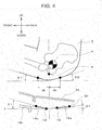
- Fig. 4 is a partially enlarged cross-sectional view illustrating the seat cushion S2 cut in the front to back direction. Furthermore, in Fig. 4 , the left side indicates the front side of the seat cushion S2, and the right side thereof indicates the rear side of the seat cushion S2.
- the respective corrugated planes of the front spring 14 and the rear spring 15 are disposed to be inclined with respect to the horizontal direction (the horizontal plane X). Then, the front spring 14 is disposed so that the rear side thereof is inclined downward (inclined rearward), and the rear spring 15 is disposed so that the front side thereof is inclined downward (inclined forward) or is disposed horizontally.
- the front spring 14 is disposed so that a surface being in contact with the cushion pad 2a and supporting the pad (a pad contact surface 14a with respect to the cushion pad 2a) is inclined rearward with respect to the horizontal plane X
- the rear spring 15 is disposed so that a surface being in contact with the cushion pad 2a and supporting the pad (a pad contact surface 15a with respect to the cushion pad 2a) is inclined forward with respect to the horizontal plane X or is parallel to the horizontal plane X.
- the degree of the small angle (the acute angle) is denoted by ⁇ 1 among the angles which are formed between the surface which is formed by the corrugated shape of the front spring 14 (the pad contact surface 14a with respect to the cushion pad 2a) and the horizontal plane X
- the degree of the small angle (the acute angle) is denoted by ⁇ 2 among the angles formed between the surface which is formed by the corrugated shape of the rear spring 15 (the pad contact surface 15a with respect to the cushion pad 2a) and the horizontal plane X
- the angles ⁇ 1 and ⁇ 2 are set as different angles.
- angles ⁇ 1 and ⁇ 2 depending on the shape of the buttocks of the occupant C having a general physical size (more specifically, the angles ⁇ 1 ' and ⁇ 2 ' inclined with respect to the seat surface: ⁇ 1 ' indicates the angle which is formed between the horizontal plane X and the line passing through the ischial tuberosity P of the occupant C and the buttocks of the occupant C separated by 80 mm from the ischial tuberosity P in the front direction and ⁇ 2 ' indicates the angle which is formed between the horizontal plane X and the line passing through the ischial tuberosity P of the occupant C and the buttocks of the occupant C separated from the ischial tuberosity by 80 mm in the back direction), and the relation of ⁇ 1 > ⁇ 2 is established in the present invention.
- the seat cushion S2 may easily follow the shape of the buttocks of the occupant C due to the front spring 14 and the rear spring 15 with such configurations, the occupant C may have a satisfactory fit comfort. Further, since the front spring 14 and the rear spring 15 are separated from each other by a predetermined distance, the ischial tuberosity P of the occupant C may be supported by a portion between the front spring 14 and the rear spring 15 (a portion obtained by the separation by the predetermined distance). As a result, the ischial pressure is reduced, and hence the seat cushion S2 providing a more satisfactory sitting comfort may be obtained.
- the value of ⁇ 1 is set in consideration of the deflection of the cushion pad 2a and is set so that a difference in height between the pan frame 12 and the front end of the front spring 14 disposed at the front side is not large.
- the occupant C feels a different in height at the boundary portion between the pan frame 12 and the front spring 14, and hence the sitting comfort is degraded.
- the seat cushion S2 providing a satisfactory sitting comfort may be obtained.
- the value of ⁇ 1 is optimally 19° in consideration of the bending of the front spring 14.
- the cushion pad 2a needs to be thinned. For this reason, the buttocks of the occupant C easily contact with the rear spring 15, and hence the sitting comfort is degraded.
- the thickness of the cushion pad 2a may be ensured. Accordingly, the occupant C does not feel 1 the sense of hitting a bottom during the sitting operation.
- the value of ⁇ 2 is optimally 0°.
- the deflection amount of the cushion pad 2a may be absorbed by the expansion and the contraction of the spring due to the front spring 14 and the rear spring 15 with the above-described configuration, the sitting comfort is further improved.
- the front elastic member and the rear elastic member are respectively formed as S-shaped springs, but for example, an elastic member such as a band-shaped rubber member having a predetermined width may be used as the front elastic member and the rear elastic member.
- an elastic member such as a band-shaped rubber member having a predetermined width
- the upper surface is disposed to be inclined with respect to the horizontal direction.
- the elastic members are disposed to satisfy the above-described values of ⁇ 1 and ⁇ 2 .
- the seat cushion S2 of the present invention has high following capability to the occupant C and has a satisfactory fit comfort.
- the seat cushion S2 of the present invention has a satisfactory cushioning property without separately providing another shock absorbing member, and hence may reduce the vibration.
- the front spring 14 and the rear spring 15 are disposed while being separated from each other by a predetermined distance in the seat cushion S2 of the present invention, it is possible to reduce the pressure (the ischial pressure) directly below the ischial tuberosity of which the sitting pressure is the highest during the sitting operation.
- the seat cushion S2 of the present invention has a satisfactory fit comfort, may reduce the vibration, and may further reduce the ischial pressure. Accordingly, the occupant C may feel an extremely satisfactory sitting comfort. Further, since the seat cushion S2 of the present invention has a simple and light-weight configuration without increasing the number of components, the working efficiency when assembling the seat cushion S2 (the vehicle seat S) to the vehicle is improved.
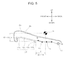
- Fig. 5 illustrates a cross-sectional view obtained by cutting the seat cushion S2 in the front to back direction. Furthermore, in Fig. 5 , the left side indicates the front side of the seat cushion S2 and the right side indicates the rear side of the seat cushion S2.
- the position of a rear end 12e of the support surface 12c of the pan frame 12 (that is, the boundary portion between the support surface 12c and the rear bent portion 12b) is defined based on the position of the hip point H of the three-dimensional mannequin.
- a ratio of ⁇ with respect to ⁇ that is, ⁇ / ⁇ satisfies the relation of 0.73 ⁇ ⁇ / ⁇ ⁇ 1.09 when the height from the rear end 12e to the hip point H (the distance in the vertical direction) is denoted by ⁇ and the distance between the rear end 12e and the hip point H in the front to back direction (here, the hip point H is located behind the rear end 12e) is denoted by ⁇ .
- the vibration characteristics in the vehicle running state are improved, and the satisfactory sitting comfort may be obtained without feeling a sense of a foreign body. Furthermore, at this time, the meaning that the "vibration characteristics are improved" indicates that the resonance magnification decreases and the resonance frequency increases. The vibration characteristics will be described below in detail.
- the pan frame 12 is attached to the side frames 11 and 11 so that the values of the ⁇ and the ⁇ have the above-described ranges, the vibration characteristics are improved.
- ⁇ exceeds 105 mm or ⁇ exceeds 116 mm
- the vibration characteristics may not be improved.
- ⁇ is smaller than 85 mm and ⁇ is smaller than 96 mm, the occupant's buttocks feel the sense of hitting the bottom surface or feel the foreign body during the sitting operation, and hence the sitting comfort is degraded.
- the area of the pan frame may be decreased compared to the configuration in which the heavy-weight pan frame is installed in the entire surface.
- the seat base frame F may be decreased in weight and the vibration characteristics in the vehicle running state or the sitting comfort of the occupant C may be improved.
- the seat cushion S2 of the present invention may improve the vibration characteristics. Also, the cushion pad 2a may easily follow the human body (the buttocks) of the occupant C and the ischial pressure is reduced. Accordingly, the occupant C may feel an extremely satisfactory sitting comfort. Further, since there is no need to provide a complex device as the configuration of improving the following capability of the cushion pad 2a, the weight does not increase.
- Fig. 6 is a graph illustrating the sitting shape of the seat cushion S2 (the displacement amount in the height direction) when the occupant C (the subject) sits on the seat cushion.
- the following capability (the fit comfort) with respect to the human body (the buttocks) of the occupant C is illustrated when the horizontal axis indicates the front to back direction of the seat cushion S2 and the vertical axis indicates the displacement amount of the upper surface (the occupant contact surface) of the seat cushion S2 in the height direction.
- the reference numeral P of Fig. 6 indicates the position of the ischial tuberosity P of the occupant C.
- the displacement amount at the position of the ischial tuberosity P is the same in Example and Comparative Example, and the occupant C is supported with the smaller displacement at the front and rear ends of the seat cushion S2 in Example of the present invention. Accordingly, it is proved that the seat cushion S2 of the present invention has a high following capability, that is, a fit comfort with respect to the occupant C.
- the cushion pad 2a may easily follow the occupant C by employing a configuration in which the front spring 14 and the rear spring 15 are provided in the right and left direction, the front spring 14 is inclined rearward, and the rear spring 15 is inclined forward compared to the seat cushion in which the elastic member supporting the cushion pad 2a is provided in the front to back direction.
- the buttocks of the occupant may be satisfactorily supported at the front and rear sides of the ischial tuberosity P by employing a configuration in which the angle ⁇ 1 is set to 19° and the angle ⁇ 2 is set to 0° as the angles formed by the pad contact surface 14a of the front spring 14 and the pad contact surface 15a of the rear spring 15 with respect to the horizontal plane X.
- Fig. 7 is a graph illustrating the ischial pressure in the seat cushion S2 when the occupant C sits on the seat cushion. This measurement is performed by measuring the pressure generated when the subject sits on the seat cushion using a clothing pressure gauge (manufactured by AMI Techno) after a sensor is attached onto the cushion pad 2a (the skin material 2b) (more specifically, a portion corresponding to the ischial tuberosity P).
- a clothing pressure gauge manufactured by AMI Techno
- Example is noticeably smaller than the ischial pressure of Comparative Example. Accordingly, it is proved that the ischial pressure largely influencing the sitting comfort is reduced by employing a configuration in which the front spring 14 and the rear spring 15 are provided in the right and left direction so as to be separated from each other.
- the elastic member may not be disposed to avoid the ischial tuberosity, and hence it is difficult to reduce the ischial pressure. Accordingly, in the seat cushion S2 of the present invention, the front spring 14 and the rear spring 15 are disposed while being separated from each other by a predetermined distance, and hence the ischial tuberosity P may be located at the portion formed by the separation. Accordingly, the sitting comfort is improved.
- Fig. 8 is a graph illustrating a result of a forced vibration test (a vibration characteristic test) of the seat cushion S2.
- the horizontal axis indicates the frequency and the vertical axis indicates the resonance magnification (transmission rate).
- the seat cushion S2 of the present invention sets the position of the rear end 12e of the pan frame 12 as described above, the vibration characteristics are improved. That is, the seat cushion S2 of the present invention may shift the resonance point of the seat from the resonance zone of the human body of the occupant C and hence may further reduce the resonance magnification. As a result, the seat cushion S2 of the present invention may effectively reduce the resonance in the vehicle running state and provides a satisfactory sitting comfort.
- the elastic member provided in the seat base frame is installed in the right and left direction and the number thereof is four.
- the number of the elastic members decreases and the installation direction is set as the front to back direction. Accordingly, it is expected that the vibration characteristics are further improved.
- Fig. 9 is a graph illustrating a result of a load deflection test (a load characteristic test) of the seat cushion S2.
- the horizontal axis indicates the displacement amount of the seat cushion S2 and the vertical axis indicates the load applied to the seat cushion S2.
- the hardness is substantially the same in the load range of the static sitting (the normal sitting) region as that of the seat cushion of Comparative Example, but the hardness in the load range of the vibration sitting region is larger than that of the seat cushion of Comparative Example.
- the seat cushion S2 of the present invention sets the position of the rear end 12e of the pan frame 12 as described above, the high hardness with respect to a high load is achieved. As a result, the vibration characteristics of the seat cushion S2 of the present invention are improved, and hence the satisfactory sitting comfort may be obtained.
- the seat base frame F of the front seat of the automobile has been described as a specific example, but the present invention is not limited thereto.
- the same configuration may be also applied to the seat base frame of the rear seat.
Landscapes
- Engineering & Computer Science (AREA)
- Aviation & Aerospace Engineering (AREA)
- Transportation (AREA)
- Mechanical Engineering (AREA)
- Seats For Vehicles (AREA)
Abstract
Description
- The present invention relates to a seat cushion and a vehicle seat, and particularly, to a seat cushion and a vehicle seat that easily follow a human body of an occupant, have satisfactory vibration characteristics, and provide an excellent sitting comfort.
- Generally, in a vehicle seat, a seat portion (seat cushion) supporting buttocks and thighs of an occupant is provided in a manner that a cushion pad is placed on a seat base frame and is covered with a skin material (trim cover). In such a seat cushion, various structures have been proposed in order to provide a satisfactory sitting comfort for the occupant.
- As a factor that influences the sitting comfort, the following capability (fit comfort) of the seat cushion with respect to the occupant or the vibration characteristics in the vehicle running state may be exemplified. In particular, the vibration characteristics may easily influence the occupant sitting on the seat cushion for a long period of time.
- In a vehicle such as an automobile or an electrical train, a vibration is generated from a floor surface in a vehicle running state. When the vibration generated at this time is transmitted to the vehicle seat, the seat cushion is vibrated at a low frequency (about 3 to 4 Hz). As a result, since the human body of the sitting occupant resonates with the seat cushion, the sitting comfort may be degraded.
- On the contrary, as a technique of reducing a vibration in a low-frequency bandwidth generated by the seat cushion in the vehicle running state and hence ensuring a satisfactory sitting comfort of the seat cushion, a technique of providing a seat suspension device is proposed, but there is a problem of complex structure and size increase.
- As a technique of ensuring the satisfactory sitting comfort of the seat cushion, for example, a technique is known which reduces a vibration transmitted from a vehicle body and reduces a resonance. In such a technique, specifically, a seat cushion may be exemplified in which a pan frame is provided and a plurality of S-shaped springs are installed at positions corresponding to the buttocks of the occupant in the pan frame. When the seat cushion has the above-described configuration, a satisfactory cushion property may be obtained by the elastic deformation of the S-shaped springs and the cushion pad. As a result, it is possible to reduce the vibration transmitted from the vehicle body in the vehicle running state.
- Regarding the seat cushion having a configuration in which such a pan frame is provided with the S-shaped springs,
Patent Document 1 discloses a seat cushion which further reduces a vibration. In the seat cushion disclosed inPatent Document 1, a seat cushion is disclosed in which a recessed buttocks receiving portion (air room) is formed in a pan frame at a position corresponding to the buttocks of the occupant. In the seat cushion, the air room is a space which is formed between the pan frame and a cushion pad (described as a "seat pad" in Patent Document 1) placed on the pan frame, and an orifice communicating with the air room is formed in a wall surface of the pan frame. - By the above-described configuration, in the seat cushion disclosed in
Patent Document 1, air satisfactorily flows out of the air room with the compressive deformation of the cushion pad, and hence the seat cushion itself may reduce the vibration. - Further, as a technique involved with the seat cushion having a satisfactory sitting comfort, a technique of reducing a sitting pressure at a specific position influencing a sitting comfort is disclosed in
Patent Document 2. - In the seat cushion (described as a "sitting pressure reduction seat" in Patent Document 2) disclosed in
Patent Document 2, a hole or a concave portion is formed directly below an ischial tuberosity of an occupant in a pan frame so as to decrease the pressure directly below the ischial tuberosity (the pressure of the portion with the highest sitting pressure). -
- Patent Document 1:
JP 1997(H09)-117346 A - Patent Document 2:
JP 2004-255208 A - In the seat cushion disclosed in
Patent Document 1, since the S-shaped springs are installed in the pan frame so as to be located at the positions corresponding to the buttocks of the occupant, the cushion pad may easily follow the human body of the occupant. Then, since the S-shaped springs are installed above the air room, the vibration may be reduced without separately providing the suspension device or the like. - However, in the seat cushion of
Patent Document 1, the pan frame as the seat base frame is provided in the entire surface of the seat base frame, and the pan frame needs to be disposed to the portion corresponding to not only the thighs of the occupant but also the buttocks thereof. As a result, a problem arises that the weight is large. Accordingly, it is desirable to devise a seat cushion which further improves a sitting comfort by a simple and light-weight configuration of the seat cushion and high following capability to an occupant. - Further, in
Patent Document 2, since the cushion pad (described as a "cushion member" in Patent Document 2) is placed on the pan frame provided with the hole or the concave portion, the sitting pressure (the ischial pressure) is reduced. However, since the upward biasing force is not exerted when the cushion pad is deflected by the load of the occupant, a problem arises that the following capability to the human body of the occupant is not satisfactory. - Accordingly, a technique has been desired which provides a seat cushion that has high following capability to a human body of an occupant (that is, a satisfactory fit comfort), has a low sitting ischial pressure, and has a satisfactory sitting comfort.
- It is an object of the present invention to provide a seat cushion and a vehicle seat which provide a satisfactory sitting comfort with a simple and light-weight configuration and high following capability to an occupant. Further, it is another object of the present invention to provide a seat cushion and a vehicle seat which provide a satisfactory sitting comfort due to high following capability to a human body of an occupant and a decreased sitting ischial pressure. Furthermore, it is still another object of the present invention to provide a seat cushion and a vehicle seat which provide a satisfactory sitting comfort due to satisfactory vibration characteristics.
- According to the present invention, the above-described problems are solved by a seat cushion including: a seat base frame; a cushion pad which is placed on the seat base frame; and a skin material which covers the seat base frame and the cushion pad, in which the seat base frame includes a pair of side frames that extends in the front to back direction, a front elastic member that is installed in the pair of side frames and is in contact with the cushion pad, and a rear elastic member that is disposed while being separated from the front elastic member by a predetermined distance and is in contact with the cushion pad, in which a pad contact surface of the front elastic member is disposed to be inclined rearward with respect to a horizontal plane, and in which a pad contact surface of the rear elastic member is disposed to be inclined forward with respect to the horizontal plane or to be parallel thereto.
- In this way, in the seat cushion of the present invention, two elastic members are provided to be laid across the side frames. Then, the elastic members (the front elastic member and the rear elastic member) provided at two positions support the cushion pad placed on the seat base frame. At this time, the pad contact surface (that is, the upper surface of the front elastic member) of the front elastic member is disposed to be inclined rearward with respect to the horizontal plane (the rear side of the pad contact surface is inclined downward). Further, the pad contact surface (that is, the upper surface of the rear elastic member) of the rear elastic member is disposed to be inclined forward with respect to the horizontal plane (the front side of the pad contact surface is inclined downward) or to be horizontal.
- Meanwhile, since the buttocks of the occupant is curved and bulge downward, the buttocks push the cushion pad downward while deflecting the cushion pad downward during the sitting operation. At this time, in the contact surface of the cushion pad with respect to the buttocks of the occupant, the front and rear sides of the buttocks are inclined upward.
- Accordingly, in the seat cushion of the present invention, when the occupant sits on the seat cushion, the upward biasing force is exerted on the cushion pad by the front elastic member inclined rearward and the rear elastic member inclined forward, and hence the cushion pad easily follows the buttocks of the occupant. Accordingly, a satisfactory sitting comfort may be obtained.
- Further, since the front elastic member and the rear elastic member are disposed while being separated from each other, the ischial tuberosity of the occupant may be located between the front elastic member and the rear elastic member. As a result, the seat cushion of the present invention may provide a satisfactory sitting comfort for the occupant by reducing the ischial pressure.
- Further, since the light-weight elastic member is used as the configuration in which the cushion pad follows the buttocks of the occupant without using a large pan frame, the weight of the seat cushion does not increase.
- At this time, when a degree of an acute angle formed between the pad contact surface of the front elastic member and the horizontal plane is denoted by θ1 and a degree of an acute angle formed between the pad contact surface of the rear elastic member and the horizontal plane is denoted by θ2, a relation of θ1 > θ2 may be established.
- In this way, since the rearward inclined angle θ1 of the front elastic member is set to be larger than the forward inclined angle θ2 of the rear elastic member, the cushion pad may easily follow the buttocks of the occupant.
- Further, at this time, when a ratio between the θ1 and the θ2 is denoted by θ2/θ1, a relation of 0 ≤ θ2/θ1 ≤ 0.18 may be established.
- In this way, since the ratio between θ2 and θ1 is set in the above-described range, the cushion pad may further easily follow the buttocks of the occupant in consideration of the deflection amount of the cushion pad.
- Moreover, the θ1 may be in the range of 17 to 21°, and the θ2 may be in the range of 0 to 3°.
- In this way, when the values of θ1 and θ2 are set in the above-described range, the cushion pad may easily follow the buttocks of the occupant and the occupant does not feel any difference in height by the elastic member or does not feel the sense of hitting the bottom surface. Further, when θ2 is set to the above-described value, the thickness of the cushion pad may be ensured without decreasing the thickness of the cushion pad too much compared to the case where θ2 is set to be larger than the above-described value, and hence the more satisfactory sitting comfort may be provided for the occupant.
- At this time, the seat base frame may further include a plate-shaped frame installed in the pair of side frames, and the plate-shaped frame may be disposed in front of the front elastic member.
- In this way, when the seat base frame further includes the plate-shaped frame and the plate-shaped frame is disposed in front of the front elastic member, the thighs of the occupant may be supported. Accordingly, in the seat cushion with the above-described configuration, the occupant contact portion (the buttocks and the thigh) may be reliably supported and the satisfactory sitting comfort may be obtained. Further, since the plate-shaped frame is provided only in the portion corresponding to the thigh, the weight of the seat cushion does not increase too much.
- Further, a rear end of the plate-shaped frame may be provided to satisfy a relation of 0.73 ≤ α/β ≤ 1.09 when a height from the rear end to a hip point of a three-dimensional mannequin based on SAE J-826 is denoted by α, a distance from the rear end to the hip point in the front to back direction is denoted by β, and a ratio between the α and the β is denoted by α/β.
- In this way, in the seat cushion of the present invention, the rear end of the plate-shaped frame is disposed at the above-described position. For this reason, the seat cushion of the present invention may have an extremely light weight compared to the seat cushion in which the pan frame is used in the entire surface of the seat base frame and the pan frame is provided from the position of the thighs of the occupant to the buttocks thereof.
- However, when only the area of the pan frame is decreased, the weight of the seat base frame may be decreased, but the range in which the pan frame supports the occupant is not sufficient. As a result, there is a concern that the vibration characteristics may be degraded.
- Meanwhile, in the seat cushion of the present invention, the rear end of the pan frame is disposed at the above-described position, and hence a seat cushion having a satisfactory vibration characteristic and a light weight may be provided.
- More specifically, in the seat cushion of the present invention, the position of the rear end of the pan frame is set as described above. Accordingly, the resonance magnification with respect to the vibration transmitted from the vehicle is reduced compared to the seat cushion in which the pan frame does not have the above-described configuration, and hence the resonance frequency further increases. As a result, since the resonance frequency of the seat cushion is shifted from the resonance zone of the human body of the occupant, the vibration of the vehicle is not easily transmitted to the occupant. Accordingly, the seat cushion of the present invention may be decreased in weight and improve the vibration characteristics. Thus, a satisfactory sitting comfort may be provided for the occupant.
- At this time, the α may be in the range of 85 to 105 mm, and the β may be in the range of 96 to 116 mm.
- In this way, since the rear end of the plate-shaped frame is disposed in the above-described range, the vibration characteristics are further improved.
- According to the present invention, the above-described problems are solved by a vehicle seat including any one of the above-described seat cushions and a seatback.
- In this way, the vehicle seat of the present invention has the above-described light-weight and simple configuration, and includes the seat cushion which provides a satisfactory sitting comfort. Accordingly, the vehicle seat may be provided which has a light weight as a whole and has a satisfactory sitting comfort.
- According to the present invention, since the light-weight elastic member biases the cushion pad upward with a predetermined angle, the seat cushion may be provided which causes the cushion pad to easily follow the buttocks of the occupant with a simple and light-weight configuration and obtains a satisfactory sitting comfort. Further, since the front elastic member and the rear elastic member are disposed while being separated from each other in the front to back direction, the ischial pressure may be reduced, and hence the seat cushion with a satisfactory sitting comfort may be provided.
- According to the present invention, since the elastic members are disposed to easily follow the shapes of the buttocks of the occupant, the cushion pad may further easily follow the buttocks of the occupant. Accordingly, the seat cushion with a satisfactory sitting comfort may be provided.
- According to the present invention, since the elastic members are disposed considering the deflection of the cushion pad, the cushion pad may further easily follow the buttocks of the occupant, and hence the sitting comfort may be improved.
- According to the present invention, since the elastic members are attached so that the occupant does not feel any height difference or does not feel the sense of hitting the bottom surface due to the elastic members, the seat cushion with a satisfactory sitting comfort may be provided. Further, the satisfactory sitting comfort may be provided for the occupant without thinning the cushion pad even when the cushion pad is disposed at the rear side of the seat cushion.
- According to the present invention, since the thighs may be also reliably supported when the occupant sits on the seat cushion, the sitting comfort is further improved. Further, since the plate-shaped frame is provided only in the portion corresponding to the thigh, the seat cushion may be provided which has a satisfactory sitting comfort and a light weight.
- According to the present invention, since the seat cushion has a light-weight and simple configuration and has a satisfactory sitting comfort, the vehicle seat may be provided which has a light weight and a satisfactory sitting comfort.
- According to the present invention, since the resonance of the human body of the occupant with respect to the vibration from the vehicle body does not easily occur when the occupant sits on the seat cushion, the vibration characteristics are satisfactory, and hence the seat cushion may be provided which obtains a satisfactory sitting comfort.
-
-
Fig. 1 is a schematic perspective view illustrating a vehicle seat according to an embodiment of the present invention; -
Fig. 2 is a schematic perspective view illustrating a seat base frame according to an embodiment of the present invention; -
Fig. 3 is an explanatory diagram illustrating a state where an occupant sits on a seat cushion according to an embodiment of the present invention; -
Fig. 4 is an explanatory diagram illustrating a configuration of an elastic member according to an embodiment of the present invention; -
Fig. 5 is an explanatory diagram illustrating a configuration of a plate-shaped frame according to an embodiment of the present invention; -
Fig. 6 is a graph illustrating sitting shapes of seat cushions according to Example and Comparative Example of the present invention; -
Fig. 7 is a graph illustrating magnitudes of ischial pressures in the seat cushions according to Example and Comparative Example of the present invention; -
Fig. 8 is a graph illustrating resonance magnifications of the seat cushions according to Example and Comparative Example of the present invention; and -
Fig. 9 is a graph illustrating load characteristics of the seat cushions according to Example and Comparative Example of the present invention. - Hereinafter, an embodiment of the present invention will be described by referring to the drawings. Furthermore, the components, the arrangements, and the like to be described later do not limit the present invention and may be, of course, modified into various forms without departing from the spirit of the present invention. Further, in the present specification, a vehicle indicates a ground running conveyance such as an automobile and a train with wheels and a conveyance such as an airplane and a ship moving in a place other than a ground. That is, the vehicle indicates a conveyance to which a seat is attachable. Further, a normal sitting load includes a sitting impact generated by a sitting operation and an acceleration load generated by a sudden starting operation of a conveyance.
- Further, the terms representing the directions in the present specification are defined as the respective directions of
Fig. 1 . That is, the right and left direction indicates the width direction of the vehicle seat, the left side when viewed from the sitting occupant indicates the left direction, and the right side when viewed from the sitting occupant indicates the right direction. Further, the front direction indicates the front side when viewed from the sitting occupant, and the back direction indicates the rear side when viewed from the sitting occupant. - Further, in the present specification, the "hip point" and the "H point" indicate the rotation center point that connects a torso and each thigh of a three-dimensional mannequin based on US-SAE standard J-826 (SAE-3 DM manufactured by ITOU SEIKI). Further, the "ischial tuberosity" indicates a portion which is located at the lowermost side of a pelvis of an occupant.
-
Figs. 1 to 5 relate to an embodiment of the present invention, in whichFig. 1 is a schematic perspective view illustrating a vehicle seat,Fig. 2 is a schematic perspective view illustrating a seat base frame,Fig. 3 is an explanatory diagram illustrating a state where an occupant sits on a seat cushion,Fig. 4 is an explanatory diagram illustrating a configuration of an elastic member, andFig. 5 is an explanatory diagram illustrating a configuration of a plate-shaped frame.Figs. 6 to 9 relate to seat cushions according to Example and Comparative Example of the present invention, in whichFig. 6 is a graph illustrating a sitting shape,Fig. 7 is a graph illustrating magnitudes of ischial pressures,Fig. 8 is a graph illustrating resonance magnifications, andFig. 9 is a graph illustrating load characteristics. - Referring to
Figs. 1 to 5 , a vehicle seat S according to an embodiment will be described. - As illustrated in
Fig. 1 , the vehicle seat S includes a seatback S1 (back portion), a seat cushion S2, and a headrest S3, and the seatback S1 and the seat cushion S2 are formed in a manner thatcushion pads 1a and 2a are placed on seat frames and are covered withskin materials pad material 3a is disposed on a head core (not illustrated) and is covered with askin material 3b. Further, thereference numeral 20 indicates a headrest pillar which supports the headrest S3. - The seat frame of the vehicle seat S includes a seat back frame (not illustrated) which forms the seatback S1 and a seat base frame F which forms the seat cushion S2.
- As described above, the seatback S1 is formed in a manner that the cushion pad 1a is placed on the seat back frame and is covered with the
skin material 1b from the upside of the cushion pad 1a, and is used to support a back of an occupant C from the rear side. - As described above, the seat cushion S2 is formed in a manner that the
cushion pad 2a is placed on the seat base frame F and is covered with theskin material 2b from the upside of thecushion pad 2a, and is used to support the occupant C from the downside. The seat base frame F is supported by leg portions (not illustrated), and inner rails are attached to the leg portions, so that the position of the seat base frame may be adjusted in a slidable manner in the front to back direction by the sliding movement between the inner rails and outer rails provided in a vehicle body floor. - Further, the rear end of the seat base frame F is connected to a seat back frame (not illustrated) through a reclining mechanism (not illustrated).
- In this embodiment, the seat base frame F is substantially formed in a rectangular shape as illustrated in
Fig. 2 , and includes side frames 11 and 11 which are separated from each other in the right and left direction, apan frame 12 which serves as a plate-shaped frame installed at the front side (the front ends) of the side frames 11 and 11, amember pipe 13 which serves as a connection member disposed at the rear side of the side frames 11 and 11, afront spring 14 which serves as a front elastic member installed in the side frames 11 and 11, and arear spring 15 which serves as a rear elastic member. - Furthermore, the
pan frame 12 and themember pipe 13 are both installed in the side frames 11 and 11, and connect the side frames 11 and 11 to each other. - Since two (the pair of) side frames 11 form the width of the seat base frame F, the side frames are disposed while being separated from each other in the right and left direction and are disposed to extend in the front to back direction. Further, the
member pipe 13 is attached to the rear side of the pair of side frames 11 and 11, and the pair of side frames 11 and 11 is connected to each other by themember pipe 13. - Further, the
pan frame 12 is fixed and joined to the front side of the pair of side frames 11 and 11, and the pair of side frames 11 and 11 is connected to each other even by thepan frame 12. More specifically, the ends of thepan frame 12 in the right and left direction are respectively fixed toflanges - The
pan frame 12 is a metallic frame of which the upper surface is substantially formed in a flat rectangular shape so as to mainly support the thighs of the occupant C. Furthermore, as illustrated inFig. 2 , the upper surface of thepan frame 12 may be provided with aconvex portion 12d which prevents a submarine phenomenon generated by the rear collision or a positional deviation during the sitting operation. - Then, as illustrated in
Fig. 3 , thepan frame 12 includes a frontbent portion 12a of which a front end is bent downward and a rearbent portion 12b of which a rear end is bent downward. Further, asupport surface 12c of which an upper surface is substantially flat and is slightly inclined downward in the back direction is provided between the frontbent portion 12a and the rearbent portion 12b. Furthermore, the ends of thesupport surface 12c in the right and left direction are respectively fixed to theflanges Fig. 2 ). - The end of the
skin material 2b is locked to the end (the lower end) of the frontbent portion 12a of thepan frame 12. Furthermore, as a method of locking theskin material 2b and the frontbent portion 12a to each other, an existing method such as a trim cord is used. - The
front spring 14 and therear spring 15 are disposed at the rear side in relation to the rearbent portion 12b of thepan frame 12. Thefront spring 14 and therear spring 15 are laid across the side frames 11 and 11, and both ends of thefront spring 14 and therear spring 15 are respectively locked to lockportions lock portion 11c is provided in theside frame 11, two holes are formed while being separated from each other in the front to back direction, and a portion interposed between the holes bulges toward the inside of theside frame 11. Then, the end of thefront spring 14 or therear spring 15 is inserted from one hole so that a part of the spring follows the bulging portion and the end is inserted through the other hole. - In this way, the ends of the
front spring 14 and therear spring 15 are supported by thelock portion 11c having a bulging surface formed in the front to back direction. - The
front spring 14 and therear spring 15 are separated from each other by a predetermined distance (about 50 to 70 mm from the rear end of thefront spring 14 to the front end of the rear spring 15) when the seat base frame F is directly viewed from the upside (that is, in planar view), and are disposed so that the extension directions are substantially parallel to each other. - Further, a position corresponding to an ischial tuberosity P of the occupant C is supported between the
front spring 14 and the rear spring 15 (a space formed by the separation by the predetermined distance). That is, thefront spring 14 and therear spring 15 are disposed while being separated from each other so that both springs are not disposed below at least the position of the ischial tuberosity P. - The
front spring 14 and therear spring 15 are linear members that are formed in a corrugated shape (a zigzag shape) or the like, and mainly support the buttocks of the occupant C. Then, the ends of thefront spring 14 and therear spring 15 are respectively journaled to the side frames 11 and 11, and thecushion pad 2a is placed above thefront spring 14 and therear spring 15. - The planes (the planes formed in a corrugated shape) having the corrugated shapes of the
front spring 14 and therear spring 15 are respectively disposed to be slightly inclined with respect to the horizontal direction. Hereinafter, the inclination angle will be described in detail. -
Fig. 4 is a partially enlarged cross-sectional view illustrating the seat cushion S2 cut in the front to back direction. Furthermore, inFig. 4 , the left side indicates the front side of the seat cushion S2, and the right side thereof indicates the rear side of the seat cushion S2. - As illustrated in
Fig. 4 , the respective corrugated planes of thefront spring 14 and therear spring 15 are disposed to be inclined with respect to the horizontal direction (the horizontal plane X). Then, thefront spring 14 is disposed so that the rear side thereof is inclined downward (inclined rearward), and therear spring 15 is disposed so that the front side thereof is inclined downward (inclined forward) or is disposed horizontally. - In other words, the
front spring 14 is disposed so that a surface being in contact with thecushion pad 2a and supporting the pad (apad contact surface 14a with respect to thecushion pad 2a) is inclined rearward with respect to the horizontal plane X, and therear spring 15 is disposed so that a surface being in contact with thecushion pad 2a and supporting the pad (apad contact surface 15a with respect to thecushion pad 2a) is inclined forward with respect to the horizontal plane X or is parallel to the horizontal plane X. - At this time, as illustrated in
Fig. 4 , when the degree of the small angle (the acute angle) is denoted by θ1 among the angles which are formed between the surface which is formed by the corrugated shape of the front spring 14 (thepad contact surface 14a with respect to thecushion pad 2a) and the horizontal plane X and the degree of the small angle (the acute angle) is denoted by θ2 among the angles formed between the surface which is formed by the corrugated shape of the rear spring 15 (thepad contact surface 15a with respect to thecushion pad 2a) and the horizontal plane X, the angles θ1 and θ2 are set as different angles. - It is desirable to set the angles θ1 and θ2 depending on the shape of the buttocks of the occupant C having a general physical size (more specifically, the angles θ1' and θ2' inclined with respect to the seat surface: θ1' indicates the angle which is formed between the horizontal plane X and the line passing through the ischial tuberosity P of the occupant C and the buttocks of the occupant C separated by 80 mm from the ischial tuberosity P in the front direction and θ2' indicates the angle which is formed between the horizontal plane X and the line passing through the ischial tuberosity P of the occupant C and the buttocks of the occupant C separated from the ischial tuberosity by 80 mm in the back direction), and the relation of θ1 > θ2 is established in the present invention. More specifically, it is desirable that the relation of 0 ≤ 1 ≤ 0.18 be established when I = θ2/θ1 (more specifically, I = 0 when the
pad contact surface 15a is horizontal and the relation of 0 < I ≤ 0.18 is established in the other cases). - Since the seat cushion S2 may easily follow the shape of the buttocks of the occupant C due to the
front spring 14 and therear spring 15 with such configurations, the occupant C may have a satisfactory fit comfort. Further, since thefront spring 14 and therear spring 15 are separated from each other by a predetermined distance, the ischial tuberosity P of the occupant C may be supported by a portion between thefront spring 14 and the rear spring 15 (a portion obtained by the separation by the predetermined distance). As a result, the ischial pressure is reduced, and hence the seat cushion S2 providing a more satisfactory sitting comfort may be obtained. - More specifically, it is desirable that θ1 = 17 to 21° and θ2 = 0 to 3°. In this way, the value of θ1 is set in consideration of the deflection of the
cushion pad 2a and is set so that a difference in height between thepan frame 12 and the front end of thefront spring 14 disposed at the front side is not large. When the value of θ1 is set to be larger or smaller than the above-described value, the occupant C feels a different in height at the boundary portion between thepan frame 12 and thefront spring 14, and hence the sitting comfort is degraded. However, when the value of θ1 is set to the above-described value, the seat cushion S2 providing a satisfactory sitting comfort may be obtained. Furthermore, the value of θ1 is optimally 19° in consideration of the bending of thefront spring 14. - Further, when the value of θ2 is set to be larger than the above-described value, the
cushion pad 2a needs to be thinned. For this reason, the buttocks of the occupant C easily contact with therear spring 15, and hence the sitting comfort is degraded. However, when the value of θ2 is set to the above-described value, the thickness of thecushion pad 2a may be ensured. Accordingly, the occupant C does not feel 1 the sense of hitting a bottom during the sitting operation. Furthermore, in order to ensure the thickness of thecushion pad 2a, the value of θ2 is optimally 0°. - Further, since the deflection amount of the
cushion pad 2a may be absorbed by the expansion and the contraction of the spring due to thefront spring 14 and therear spring 15 with the above-described configuration, the sitting comfort is further improved. - Furthermore, a configuration has been described in which the front elastic member and the rear elastic member are respectively formed as S-shaped springs, but for example, an elastic member such as a band-shaped rubber member having a predetermined width may be used as the front elastic member and the rear elastic member. In a case where the band-shaped elastic member is used, the upper surface is disposed to be inclined with respect to the horizontal direction. That is, on the assumption that the small angle (the acute angle) is denoted by θ1 among the angles formed between the horizontal plane X and the upper surface of the elastic member disposed at the front side and the small angle (the acute angle) is denoted by θ2 among the angles formed between the horizontal plane X and the upper surface of the elastic member disposed at the rear side, the elastic members are disposed to satisfy the above-described values of θ1 and θ2.
- As described above, since the
front spring 14 is inclined rearward with respect to the horizontal plane X and therear spring 15 is inclined forward with respect to the horizontal plane X (or is disposed horizontally), the seat cushion S2 of the present invention has high following capability to the occupant C and has a satisfactory fit comfort. - Further, since the
front spring 14 and therear spring 15 have the above-described configurations, the seat cushion S2 of the present invention has a satisfactory cushioning property without separately providing another shock absorbing member, and hence may reduce the vibration. - Further, since the
front spring 14 and therear spring 15 are disposed while being separated from each other by a predetermined distance in the seat cushion S2 of the present invention, it is possible to reduce the pressure (the ischial pressure) directly below the ischial tuberosity of which the sitting pressure is the highest during the sitting operation. - Accordingly, as described above, the seat cushion S2 of the present invention has a satisfactory fit comfort, may reduce the vibration, and may further reduce the ischial pressure. Accordingly, the occupant C may feel an extremely satisfactory sitting comfort. Further, since the seat cushion S2 of the present invention has a simple and light-weight configuration without increasing the number of components, the working efficiency when assembling the seat cushion S2 (the vehicle seat S) to the vehicle is improved.
-
Fig. 5 illustrates a cross-sectional view obtained by cutting the seat cushion S2 in the front to back direction. Furthermore, inFig. 5 , the left side indicates the front side of the seat cushion S2 and the right side indicates the rear side of the seat cushion S2. - As illustrated in
Fig. 5 , the position of arear end 12e of thesupport surface 12c of the pan frame 12 (that is, the boundary portion between thesupport surface 12c and the rearbent portion 12b) is defined based on the position of the hip point H of the three-dimensional mannequin. - As illustrated in
Fig. 5 , it is desirable to provide therear end 12e of thepan frame 12 so that a ratio of α with respect to β, that is, α/β satisfies the relation of 0.73 ≤ α/β ≤ 1.09 when the height from therear end 12e to the hip point H (the distance in the vertical direction) is denoted by α and the distance between therear end 12e and the hip point H in the front to back direction (here, the hip point H is located behind therear end 12e) is denoted by β. - When the
rear end 12e of thepan frame 12 is provided at the above-described position, the vibration characteristics in the vehicle running state are improved, and the satisfactory sitting comfort may be obtained without feeling a sense of a foreign body. Furthermore, at this time, the meaning that the "vibration characteristics are improved" indicates that the resonance magnification decreases and the resonance frequency increases. The vibration characteristics will be described below in detail. - Regarding the values of the α and the β, more specifically, the values of about α = 85 to 105 mm and β = 96 to 116 mm are desirable. When the
pan frame 12 is attached to the side frames 11 and 11 so that the values of the α and the β have the above-described ranges, the vibration characteristics are improved. - When α exceeds 105 mm or β exceeds 116 mm, the vibration characteristics may not be improved. Further, when α is smaller than 85 mm and β is smaller than 96 mm, the occupant's buttocks feel the sense of hitting the bottom surface or feel the foreign body during the sitting operation, and hence the sitting comfort is degraded.
- As described above, when the position of the
rear end 12e of thepan frame 12 is set in the above-described range with respect to the hip point H of the three-dimensional mannequin, the area of the pan frame may be decreased compared to the configuration in which the heavy-weight pan frame is installed in the entire surface. As a result, the seat base frame F may be decreased in weight and the vibration characteristics in the vehicle running state or the sitting comfort of the occupant C may be improved. - Further, when the
rear end 12e of thepan frame 12 is provided in the above-described range and thefront spring 14 and therear spring 15 are provided with the above-described configuration, the seat cushion S2 of the present invention may improve the vibration characteristics. Also, thecushion pad 2a may easily follow the human body (the buttocks) of the occupant C and the ischial pressure is reduced. Accordingly, the occupant C may feel an extremely satisfactory sitting comfort. Further, since there is no need to provide a complex device as the configuration of improving the following capability of thecushion pad 2a, the weight does not increase. - Hereinafter, Example and Comparative Example of the present invention will be described by referring to
Figs. 6 to 9 . - Furthermore, in
Figs. 6 to 9 , "Example" is the seat cushion S2 of the embodiment of the present invention, and θ1 is set to 19° and θ2 is set to 0°. Further, the relation of α = 95 mm and β = 106 mm is set. - "Comparative Example" has a configuration in which four S-shaped springs are provided in the front to back direction instead of the
front spring 14 and therear spring 15 of the present invention. Further, when "Comparative Example" is compared with Example, the pan frame is small in the front to back direction (that is, β is larger than 116 mm) and the height from the rear end of the pan frame to the hip point H is large (that is, α is larger than 105 mm). Specifically, the relation of α = 115 mm and β = 153 mm is set. -
Fig. 6 is a graph illustrating the sitting shape of the seat cushion S2 (the displacement amount in the height direction) when the occupant C (the subject) sits on the seat cushion. Here, the following capability (the fit comfort) with respect to the human body (the buttocks) of the occupant C is illustrated when the horizontal axis indicates the front to back direction of the seat cushion S2 and the vertical axis indicates the displacement amount of the upper surface (the occupant contact surface) of the seat cushion S2 in the height direction. Furthermore, the reference numeral P ofFig. 6 indicates the position of the ischial tuberosity P of the occupant C. - This measurement is performed by using a strain gauge type load measuring device (manufactured by Minebea Co., Ltd.) while a stainless pipe (a thickness = 0.4 mm and a width = 40 mm) is laid in the front to back direction of the seat cushion S2 and the subject is sit on the seat cushion S2, and the sitting shape is compared. Furthermore, the subject at this time is the occupant which has a value that is the closest to the average value of the body shapes (the buttocks shapes) of forty people.
- As a result, the displacement amount at the position of the ischial tuberosity P is the same in Example and Comparative Example, and the occupant C is supported with the smaller displacement at the front and rear ends of the seat cushion S2 in Example of the present invention. Accordingly, it is proved that the seat cushion S2 of the present invention has a high following capability, that is, a fit comfort with respect to the occupant C.
- Accordingly, it is proved that the
cushion pad 2a may easily follow the occupant C by employing a configuration in which thefront spring 14 and therear spring 15 are provided in the right and left direction, thefront spring 14 is inclined rearward, and therear spring 15 is inclined forward compared to the seat cushion in which the elastic member supporting thecushion pad 2a is provided in the front to back direction. - It is proved that the buttocks of the occupant may be satisfactorily supported at the front and rear sides of the ischial tuberosity P by employing a configuration in which the angle θ1 is set to 19° and the angle θ2 is set to 0° as the angles formed by the
pad contact surface 14a of thefront spring 14 and thepad contact surface 15a of therear spring 15 with respect to the horizontal plane X. -
Fig. 7 is a graph illustrating the ischial pressure in the seat cushion S2 when the occupant C sits on the seat cushion. This measurement is performed by measuring the pressure generated when the subject sits on the seat cushion using a clothing pressure gauge (manufactured by AMI Techno) after a sensor is attached onto thecushion pad 2a (theskin material 2b) (more specifically, a portion corresponding to the ischial tuberosity P). - As a result, it is proved that the ischial pressure of Example is noticeably smaller than the ischial pressure of Comparative Example. Accordingly, it is proved that the ischial pressure largely influencing the sitting comfort is reduced by employing a configuration in which the
front spring 14 and therear spring 15 are provided in the right and left direction so as to be separated from each other. - Meanwhile, in Comparative Example in which the elastic member is provided in the front to back direction, the elastic member may not be disposed to avoid the ischial tuberosity, and hence it is difficult to reduce the ischial pressure. Accordingly, in the seat cushion S2 of the present invention, the
front spring 14 and therear spring 15 are disposed while being separated from each other by a predetermined distance, and hence the ischial tuberosity P may be located at the portion formed by the separation. Accordingly, the sitting comfort is improved. -
Fig. 8 is a graph illustrating a result of a forced vibration test (a vibration characteristic test) of the seat cushion S2. The horizontal axis indicates the frequency and the vertical axis indicates the resonance magnification (transmission rate). - This measurement is performed based on the term of JASO B407-87 "6.4 Vibration Test".
- As a result, in the seat cushion S2 of Example, it is proved that the resonance magnification decreases, the frequency is shifted to the high frequency, and the resonance point is largely shifted from the resonance zone of the human body of the occupant C.
- Meanwhile, in Comparative Example in which the pan frame is formed as a comparatively small size in the front to back direction (that is, the rear end of the pan frame is provided at a position far from the hip point H), the resonance magnification is high and the resonance point is not easily shifted from the resonance zone of the human body of the occupant C.
- Accordingly, since the seat cushion S2 of the present invention sets the position of the
rear end 12e of thepan frame 12 as described above, the vibration characteristics are improved. That is, the seat cushion S2 of the present invention may shift the resonance point of the seat from the resonance zone of the human body of the occupant C and hence may further reduce the resonance magnification. As a result, the seat cushion S2 of the present invention may effectively reduce the resonance in the vehicle running state and provides a satisfactory sitting comfort. - Further, in the seat cushion of Comparative Example, the elastic member provided in the seat base frame is installed in the right and left direction and the number thereof is four. However, in the seat cushion S2 of the present invention, the number of the elastic members decreases and the installation direction is set as the front to back direction. Accordingly, it is expected that the vibration characteristics are further improved.
-
Fig. 9 is a graph illustrating a result of a load deflection test (a load characteristic test) of the seat cushion S2. The horizontal axis indicates the displacement amount of the seat cushion S2 and the vertical axis indicates the load applied to the seat cushion S2. - This measurement is performed based on the term of JASO B407-87 "6.1 Load Test".
- As a result, in the seat cushion S2 of Example, the hardness is substantially the same in the load range of the static sitting (the normal sitting) region as that of the seat cushion of Comparative Example, but the hardness in the load range of the vibration sitting region is larger than that of the seat cushion of Comparative Example.
- Accordingly, since the seat cushion S2 of the present invention sets the position of the
rear end 12e of thepan frame 12 as described above, the high hardness with respect to a high load is achieved. As a result, the vibration characteristics of the seat cushion S2 of the present invention are improved, and hence the satisfactory sitting comfort may be obtained. - Furthermore, in the above-described embodiments, the seat base frame F of the front seat of the automobile has been described as a specific example, but the present invention is not limited thereto. For example, the same configuration may be also applied to the seat base frame of the rear seat.
-
- C
- occupant (three-dimensional mannequin)
- H
- hip point (H point)
- P
- ischial tuberosity
- S
- vehicle seat
- S1
- seatback
- S2
- seat cushion
- S3
- headrest
- F
- seat base frame
- X
- horizontal plane
- 1a, 2a, 3a
- cushion pad (pad material)
- 1b, 2b, 3b
- skin material
- 11
- side frame
- 11b
- flange
- 11c
- lock portion
- 12
- pan frame (plate-shaped frame)
- 12a
- front bent portion
- 12b
- rear bent portion
- 12c
- support surface
- 12d
- convex portion
- 12e
- rear end
- 13
- member pipe (connection member)
- 14
- front spring (front elastic member)
- 14a
- pad contact surface
- 15
- rear spring (rear elastic member)
- 15a
- pad contact surface
- 20
- headrest pillar
Claims (8)
- A seat cushion comprising:a seat base frame;a cushion pad which is placed on the seat base frame; anda skin material which covers the seat base frame and the cushion pad,wherein the seat base frame includes a pair of side frames that extends in a front to back direction, a front elastic member that is installed in the pair of side frames and is in contact with the cushion pad, and a rear elastic member that is disposed while being separated from the front elastic member by a predetermined distance and is in contact with the cushion pad,wherein a pad contact surface of the front elastic member is disposed to be inclined rearward with respect to a horizontal plane, andwherein a pad contact surface of the rear elastic member is disposed to be inclined forward with respect to the horizontal plane or to be parallel thereto.
- The seat cushion according to claim 1,
wherein when a degree of an acute angle formed between the pad contact surface of the front elastic member and the horizontal plane is denoted by θ1 and a degree of an acute angle formed between the pad contact surface of the rear elastic member and the horizontal plane is denoted by θ2, a relation of θ1 > θ2 is established. - The seat cushion according to claim 2,
wherein when a ratio between the θ1 and the θ2 is denoted by θ2/θ1, a relation of 0 ≤ θ2/θ1 ≤ 0.18 is established. - The seat cushion according to claim 3,
wherein the θ1 is in a range of 17 to 21°, and
wherein the θ2 is in a range of 0 to 3°. - The seat cushion according to any one of claims 1 to 4,
wherein the seat base frame further includes a plate-shaped frame installed in the pair of side frames, and
wherein the plate-shaped frame is disposed in front of the front elastic member. - The seat cushion according to claim 5,
wherein a rear end of the plate-shaped frame is provided to satisfy a relation of 0.73 ≤ α/β ≤ 1.09 when a height from the rear end to a hip point of a three-dimensional mannequin based on SAE J-826 is denoted by α, a distance from the rear end to the hip point in the front to back direction is denoted by β, and a ratio between the α and the β is denoted by α/β. - The seat cushion according to claim 6,
wherein the α is in a range of 85 to 105 mm, and
wherein the β is in a range of 96 to 116 mm. - A vehicle seat comprising:the seat cushion according to any one of claims 1 to 7; anda seatback.
Applications Claiming Priority (3)
| Application Number | Priority Date | Filing Date | Title |
|---|---|---|---|
| JP2011080770A JP5706219B2 (en) | 2011-03-31 | 2011-03-31 | Seat cushion and vehicle seat |
| JP2011080769A JP5730105B2 (en) | 2011-03-31 | 2011-03-31 | Seat cushion and vehicle seat |
| PCT/JP2012/058416 WO2012133675A1 (en) | 2011-03-31 | 2012-03-29 | Seat cushion and vehicle seat |
Publications (2)
| Publication Number | Publication Date |
|---|---|
| EP2692579A1 true EP2692579A1 (en) | 2014-02-05 |
| EP2692579A4 EP2692579A4 (en) | 2014-09-03 |
Family
ID=46931377
Family Applications (1)
| Application Number | Title | Priority Date | Filing Date |
|---|---|---|---|
| EP12764185.0A Withdrawn EP2692579A4 (en) | 2011-03-31 | 2012-03-29 | Seat cushion and vehicle seat |
Country Status (4)
| Country | Link |
|---|---|
| US (2) | US9308846B2 (en) |
| EP (1) | EP2692579A4 (en) |
| CN (1) | CN103517828B (en) |
| WO (1) | WO2012133675A1 (en) |
Families Citing this family (9)
| Publication number | Priority date | Publication date | Assignee | Title |
|---|---|---|---|---|
| EP2902259B1 (en) * | 2012-09-26 | 2018-11-07 | TS Tech Co., Ltd. | Vehicle seat |
| BR112015010748A2 (en) | 2012-11-16 | 2017-07-11 | Ts Tech Co Ltd | vehicle seat |
| JP6111979B2 (en) * | 2013-10-29 | 2017-04-12 | トヨタ紡織株式会社 | Vehicle seat |
| CN104260653B (en) * | 2014-09-02 | 2016-11-30 | 东莞市联洲知识产权运营管理有限公司 | A kind of detachable anemia of pregnant woman's motor vehicle seat back |
| JP6299704B2 (en) * | 2015-08-06 | 2018-03-28 | トヨタ自動車株式会社 | Vehicle seat |
| US9994135B2 (en) * | 2016-03-30 | 2018-06-12 | Ford Global Technologies, Llc | Independent cushion thigh support |
| CN109789820A (en) * | 2016-09-27 | 2019-05-21 | 普罗马有限公司 | The seat of vehicle with joint edge |
| JP6940995B2 (en) * | 2017-07-27 | 2021-09-29 | マツダ株式会社 | Vehicle seat |
| EP3530149B1 (en) * | 2018-02-22 | 2022-06-01 | Pullmaflex Benelux N.V. | Suspension arrangement for a seat and method of producing an elongate suspension member for a suspension arrangement for a seat |
Family Cites Families (12)
| Publication number | Priority date | Publication date | Assignee | Title |
|---|---|---|---|---|
| JPH0313240Y2 (en) * | 1987-02-25 | 1991-03-27 | ||
| JPH0750994Y2 (en) * | 1989-07-31 | 1995-11-22 | 株式会社タチエス | Seat cushion structure for trucks |
| JPH09117346A (en) | 1995-10-27 | 1997-05-06 | Tachi S Co Ltd | Seat cushion suspension structure |
| JP4196744B2 (en) * | 2003-06-12 | 2008-12-17 | トヨタ紡織株式会社 | Vehicle seat |
| FR2861660B1 (en) * | 2003-11-05 | 2006-03-17 | Faurecia Sieges Automobile | AUTOMOTIVE SEAT FRAME COMPRISING AN ASSEMBLY OF A PLATINUM ON A TUBE |
| JP4560661B2 (en) * | 2004-03-31 | 2010-10-13 | テイ・エス テック株式会社 | Vehicle seat with lifter mechanism with adjustable seating height |
| JP2004255208A (en) | 2004-04-26 | 2004-09-16 | Bridgestone Corp | Seat decreasing sitting pressure |
| JP4555720B2 (en) | 2005-03-31 | 2010-10-06 | シロキ工業株式会社 | seat |
| JP4556210B2 (en) * | 2005-04-11 | 2010-10-06 | 日本発條株式会社 | Vehicle seat |
| JP5153345B2 (en) * | 2005-12-28 | 2013-02-27 | 株式会社デルタツーリング | Vehicle seat |
| JP5088528B2 (en) | 2006-08-24 | 2012-12-05 | テイ・エス テック株式会社 | Reclining car seat |
| US8162402B2 (en) | 2008-10-27 | 2012-04-24 | Toyota Boshoku Kabushikia Kaisha | Vehicular seats |
-
2012
- 2012-03-29 US US14/007,684 patent/US9308846B2/en active Active
- 2012-03-29 EP EP12764185.0A patent/EP2692579A4/en not_active Withdrawn
- 2012-03-29 WO PCT/JP2012/058416 patent/WO2012133675A1/en not_active Ceased
- 2012-03-29 CN CN201280021622.1A patent/CN103517828B/en not_active Expired - Fee Related
-
2016
- 2016-03-17 US US15/073,190 patent/US9511699B2/en active Active
Also Published As
| Publication number | Publication date |
|---|---|
| US9308846B2 (en) | 2016-04-12 |
| CN103517828A (en) | 2014-01-15 |
| US20160193947A1 (en) | 2016-07-07 |
| US20140021769A1 (en) | 2014-01-23 |
| US9511699B2 (en) | 2016-12-06 |
| CN103517828B (en) | 2016-03-16 |
| WO2012133675A1 (en) | 2012-10-04 |
| EP2692579A4 (en) | 2014-09-03 |
Similar Documents
| Publication | Publication Date | Title |
|---|---|---|
| US9511699B2 (en) | Seat cushion and vehicle seat | |
| US8936317B2 (en) | Seat back for vehicle and seat for vehicle including the same | |
| JP5513212B2 (en) | Vehicle seat back and vehicle seat provided with the same | |
| US9573503B2 (en) | Vehicle seat | |
| JP6842045B2 (en) | Sheet | |
| JP5956592B2 (en) | Vehicle seat | |
| JP2022179711A (en) | vehicle seat | |
| JP2022179712A (en) | vehicle seat | |
| JP2019034641A (en) | Vehicle seat | |
| JP6068114B2 (en) | Vehicle seat and vehicle | |
| JP5730105B2 (en) | Seat cushion and vehicle seat | |
| JP6453414B2 (en) | Seat cushion and vehicle seat | |
| JP5706219B2 (en) | Seat cushion and vehicle seat | |
| JP5956628B2 (en) | Seat cushion and vehicle seat | |
| JP6224172B2 (en) | Seat cushion and vehicle seat | |
| JP2016164073A (en) | Vehicle seat | |
| JP5956593B2 (en) | Vehicle seat | |
| JP6522090B2 (en) | Vehicle seat | |
| WO2014049757A1 (en) | Vehicle seat |
Legal Events
| Date | Code | Title | Description |
|---|---|---|---|
| PUAI | Public reference made under article 153(3) epc to a published international application that has entered the european phase |
Free format text: ORIGINAL CODE: 0009012 |
|
| 17P | Request for examination filed |
Effective date: 20131030 |
|
| AK | Designated contracting states |
Kind code of ref document: A1 Designated state(s): AL AT BE BG CH CY CZ DE DK EE ES FI FR GB GR HR HU IE IS IT LI LT LU LV MC MK MT NL NO PL PT RO RS SE SI SK SM TR |
|
| DAX | Request for extension of the european patent (deleted) | ||
| A4 | Supplementary search report drawn up and despatched |
Effective date: 20140805 |
|
| RIC1 | Information provided on ipc code assigned before grant |
Ipc: B60N 2/70 20060101AFI20140730BHEP Ipc: A47C 7/30 20060101ALI20140730BHEP Ipc: A47C 7/02 20060101ALI20140730BHEP Ipc: B60N 2/68 20060101ALI20140730BHEP |
|
| STAA | Information on the status of an ep patent application or granted ep patent |
Free format text: STATUS: THE APPLICATION HAS BEEN WITHDRAWN |
|
| 18W | Application withdrawn |
Effective date: 20160412 |