EP2692442A1 - Gyratory crusher outer crushing shell - Google Patents
Gyratory crusher outer crushing shell Download PDFInfo
- Publication number
- EP2692442A1 EP2692442A1 EP12179085.1A EP12179085A EP2692442A1 EP 2692442 A1 EP2692442 A1 EP 2692442A1 EP 12179085 A EP12179085 A EP 12179085A EP 2692442 A1 EP2692442 A1 EP 2692442A1
- Authority
- EP
- European Patent Office
- Prior art keywords
- crushing
- shell
- crushing shell
- crusher
- region
- Prior art date
- Legal status (The legal status is an assumption and is not a legal conclusion. Google has not performed a legal analysis and makes no representation as to the accuracy of the status listed.)
- Withdrawn
Links
- 230000001419 dependent effect Effects 0.000 claims 3
- 241000237983 Trochidae Species 0.000 description 16
- 241000239290 Araneae Species 0.000 description 5
- 239000000463 material Substances 0.000 description 5
- 230000000717 retained effect Effects 0.000 description 3
- 229910052500 inorganic mineral Inorganic materials 0.000 description 2
- 239000011707 mineral Substances 0.000 description 2
- 239000011435 rock Substances 0.000 description 2
- 230000000694 effects Effects 0.000 description 1
- 230000001939 inductive effect Effects 0.000 description 1
Images

Classifications
-
- B—PERFORMING OPERATIONS; TRANSPORTING
- B02—CRUSHING, PULVERISING, OR DISINTEGRATING; PREPARATORY TREATMENT OF GRAIN FOR MILLING
- B02C—CRUSHING, PULVERISING, OR DISINTEGRATING IN GENERAL; MILLING GRAIN
- B02C2/00—Crushing or disintegrating by gyratory or cone crushers
- B02C2/005—Lining
Definitions
- the present invention relates to a gyratory crusher outer crushing shell for use in a gyratory crusher in which a mounting surface of the shell comprises a camming region to inhibit the crushing shell rotating about its longitudinal axis.
- Gyratory crushers are used for crushing ore, mineral and rock material to smaller sizes.
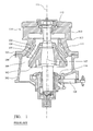
- a typical crusher comprises a frame 100 having an upper frame 101 and a lower frame 102.
- a crushing head 103 is mounted upon an elongate shaft 107.
- a first crushing shell 105 is fixably mounted on crushing head 103 and a second crushing shell 106 is fixably mounted at top frame 101.
- a crushing zone 104 is formed between the opposed crushing shells 105, 106.
- a discharge zone 109 is positioned immediately below crushing zone 104 and is defined, in part, by lower frame 102.
- Upper frame 101 may be further divided into a topshell 111, mounted upon lower frame 102 (alternatively termed a bottom shell), and a spider 114 that extends from topshell 111 and represents an upper portion of the crusher.
- Spider 114 comprises two diametrically opposed arms 110 that extend radially outward from a central cap 112 positioned on a longitudinal axis 115 extending through frame 100 and the gyratory crusher generally. Arms 110 are attached to an upper region of topshell 111 via an intermediate annular flange 113 that is centred around longitudinal axis 115.
- arms 110 and topshell 111 form a unitary structure and are formed integrally.
- a drive (not shown) is coupled to main shaft 107 via a drive shaft 108 and suitable gearing 116 so as to rotate shaft 107 eccentrically about longitudinal axis 115 and to cause crushing head 103 to perform a gyratory pendulum movement and crush material introduced into crushing gap 104.
- Gyratory crushers are used for crushing ore, mineral and rock material to smaller sizes.
- the crusher comprises a crushing head mounted upon an elongate main shaft.
- a first crushing shell is mounted on the crushing head and a second crushing shell is mounted on a frame such that the first and second crushing shells define together a crushing gap through which the material to be crushed is passed.
- a driving device is arranged to rotate an eccentric assembly arranged about the lower portion of the shaft so as to cause the crushing head to perform a gyratory pendulum movement and crush the material introduced in the crushing gap.
- the second or outer crushing shell may be mounted at the frame in a number of ways.
- US 2010/0270409 describes a mounting ring positioned intermediate between the frame and the shell.
- Further examples of outer shell mountings are described in EP 0050090 ; WO 2008/139020 ; US 5,350,125 and US 7,850,108 .
- the anchorage region is formed by an outer mounting surface of the crushing shell that creates a camming region to abut against the support structure.
- the support structure comprises an intermediate mounting ring whilst in further embodiments, the support structure comprises the surrounding frame.
- the camming surface region is provided by forming the outer crushing shell with an eccentric cross sectional wall thickness such that the rotational axis of the external facing mounting surface is eccentric relative to a rotational axis of the internal facing crushing surface.
- the mounting surface would process around the rotational axis of the crushing surface where it not for frictional locking contact with the surrounding support structure. Accordingly, the torque forces from the crushing shell are transferred over a large circumferential part of the mounting surface to reduce and eliminate any stress concentrations. That is, the anchorage and rotational lock of the outer crushing shell is provided by the mounting surface and the requirement for any tangential or radially orientated keys or locking flanges is obviated together with the creation of any unwanted stress concentrations.
- a gyratory crusher outer crushing shell comprising: a crushing surface to be orientated towards an inner crushing shell; a mounting surface for positioning against a support structure to, in part, retain the position of the outer crushing shell within a gyratory crusher; an elongate annular wall defined between the crushing surface and the mounting surface, the wall extending around a longitudinal axis of the outer crushing shell; characterised in that at a region along the length of the outer crushing shell where the mounting surface is configured to abut against the support structure, a cross sectional thickness of the wall perpendicular to the longitudinal axis is eccentric relative to a rotational axis of the crushing surface such that a rotational axis of the mounting surface is eccentric relative to the rotational axis of the crushing surface.
- the mounting surface is configured for precession about the rotational axis of the crushing surface and to abut against the support structure and prevent the outer crushing shell rotating about the rotational axis of the crushing surface.
- a cross sectional shape profile of the crushing surface is substantially circular.
- a cross sectional shape profile of the mounting surface is substantially circular.
- a region of the mounting surface in the longitudinal direction relative to the longitudinal axis is concave.
- the crushing shell further comprises a first end intended to be positioned at an upper region of the gyratory crusher and a second end intended to be positioned at a lower position at the gyratory crusher relative to the first end, the eccentric cross sectional thickness of the wall positioned at or towards the first end.
- the crushing shell further comprises a first end intended to be positioned at an upper region of the gyratory crusher and a second end intended to be positioned at a lower position at the gyratory crusher relative to the first end, the eccentric cross sectional thickness of the wall positioned substantially at a mid region in the longitudinal direction between the first and second ends.
- a gyratory crusher comprising: a frame that, in part, defines an internal crushing zone; an outer crushing shell as described herein mounted within a region of the frame; an inner crushing shell mounted upon a crushing head configured for gyroscopic procession about a longitudinal axis extending through the crushing zone.
- the support structure comprises a mounting ring positioned around a region of the outer crushing shell, the mounting ring having a support surface orientated towards the rotation axis of the crushing surface and configured to abut the mounting surface and prevent the outer crushing shell from rotation about the rotational axis.
- the ring is mounted at or towards the first end of the outer crushing shell.
- the ring is mounted at substantially the mid region between the first and second ends.
- a rotational axis of the mounting ring is eccentric relative to a rotational axis of the crushing surface.
- a cross sectional shape profile of the support surface is substantially circular.
- the mounting ring comprises at least one shoulder extending radially outward relative to the longitudinal axis, the shoulder configured to abut against a region of the frame and prevent rotation of the mounting ring about the longitudinal axis.
- the mounting ring comprises a first annular flange projecting radially inward towards the longitudinal axis and the outer crushing shell comprises a second annular flange projecting radially outward from the shell annular wall, the first and second annular flanges configured to abut one another.
- a gyratory crusher outer crushing shell comprising: a crushing surface to be orientated towards an inner crushing shell; a mounting surface for positioning against a support structure to, in part, retain the position of the outer crushing shell within a gyratory crusher; an elongate annular wall defined between the crushing surface and the mounting surface, the wall extending around a longitudinal axis of the outer crushing shell; characterised in that at a region along the length of the outer crushing shell where the mounting surface is configured to abut against the support structure, a cross sectional thickness of the wall perpendicular to the longitudinal axis is non uniform in the circumferential direction relative to a rotational axis of the crushing surface such that a cross sectional shape profile of the mounting surface is non-circular to define an anchorage region to inhibit rotation of the outer crushing shell about the longitudinal axis relative to the support structure.
- a cross sectional shape profile of the support surface of the mounting ring orientated towards the rotational axis of the crushing surface is non-circular.
- a cross sectional shape profile of the contact surfaces at the inner bearing surface of the crusher frame and the outer facing bearing surface of the annular ring is non-circular.
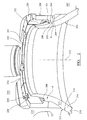
- an outer crushing shell 200 is mounted within a frame 202 of a gyratory crusher and is maintained at an approximate mid region along its length between a first upper end 210 and second lower end 211.
- Crushing shell 200 comprises a substantially annular configuration in which an annular wall 213 extends circumferentially around a longitudinal axis 212 passing centrally through shell 200.
- Annular wall 213 is defined by a crushing surface 203 orientated towards axis 212 and an opposed mounting surface 222, 204, 215 orientated to be external facing away from axis 212.
- first end 210 is orientated to be positioned above second end 211 in the longitudinal direction relative to axis 212.
- the external facing mounting surface 222, 204, 215 between ends 210 and 211 is concave such that wall 213 curves inwardly towards axis 212 from first end 210 to second end 211.
- Shell 200 is positioned at a region of frame 202 so as to be surrounded by a topshell part 218 positioned directly below a spider part 219.
- a lower annular region 214 of shell 200 is configured to abut a lower region of topshell 218.
- a portion of mounting face 215 is configured for contact against an opposed support surface 216 of topshell 218 orientated to be facing axis 212.
- topshell 200 As topshell 200 is concave along its length relative to axis 212, an upper region of shell 200 is positionally supported by a mounting ring 201. Ring 201 is also mounted within topshell 218 below spider 219. Ring 201 comprises a substantially annular geometry that comprises a bearing surface 208 orientated to be external facing relative to axis 212 and positioned opposed to a bearing surface 209 of topshell 218 orientated to be internal facing towards axis 212. Topshell bearing surface 209 comprises a plurality of shoulders 221 that project radially inward towards axis 212. Additionally, ring 201 comprises a corresponding number of shoulders 220 projecting radially outward from its annular body in a direction away from axis 212. Accordingly, shoulders 221 and 220 are configured to abut one another by having a corresponding shape profile so as to rotationally lock ring 202 within the topshell 218 relative to axis 212.
- Shell 200 comprises an annular flange 206 positioned substantially at a mid region along the shell length between first and second ends 210, 211.
- Flange 206 extends circumferentially around the wall 213 and projects radially outward from wall 213 relative to axis 212.
- a flange 207 projects radially inward from ring 210 and is orientated toward shell 200 and axis 212.
- Flange 207 also extends circumferentially around ring 201.
- the external facing mounting surface 204 of flange 206 is positioned in touching contact with an opposed support surface 205 of flange 207. Accordingly, ring 201 is effectively sandwiched in a radial direction between shell 201 and the inward facing bearing surface 209 of topshell 218.
- the shell wall 213 comprises a cross sectional thickness that is eccentric relative to a rotational axis of crushing surface 203. That is, as shown in figures 2 and 3 , the wall thickness 213 is non-uniform circumferentially around shell 200 such that at a cross section B, the wall thickness is less than a corresponding wall thickness at section A where A and B are diametrically opposed. Accordingly, a distance by which mounting surface 204 at flange 206 is separated from crushing surface 203 is non-uniform circumferentially around axis 212.
- FIG. 2 This is illustrated in figures 2 and 3 where flange 206 at section A projects radially outward by a greater distance from wall 213 than the corresponding section of flange 206 at diametrically opposed section B.
- This has the effect that the rotational axis of mounting surface 204 at the mounting region is eccentric relative to the rotational axis of crushing surface 203.
- This off-set wall thickness creates an anchorage or camming region at the shell wall 213.
- This camming region abuts support surface 205 of ring 201 to transfer torque forces to ring 201.
- the cross sectional shape profile of mounting surface 204 and the opposed support surface 205 are substantially circular, the moment of force is dissipated circumferentially around ring 201 and shell 200 to avoid creation of stress concentration.
- Ring 201 is prevented from rotation within topshell 218 as abutment shoulders 220, 221 interlock. Accordingly, the need for separate mounting pins or keyways to secure shell 200 at ring 201 and/or topshell 218 is avoided.
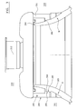
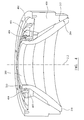
- FIGS 4 and 5 illustrate a further specific implementation of the present invention in which outer crushing shell 200 is supported at its upper end within the crusher frame 400 that is mounted above a main frame (not shown).
- Shell 200 is supported at its lower end 211 via mounting surface portion 215 being radially outward facing away from longitudinal axis 212.
- Mounting surface 215 at second end 211 is positioned in touching contact with an opposed support surface 216 orientated to be inward facing towards axis 212 and provided at frame 400. Both mounting surface 215 and support surface 216 extend circumferentially around longitudinal axis 212.
- Shell 200 is retained in position at its first end 210 by abutment with a retaining ring 401 that is, in turn, positionally held at upper frame 400 by an annular collar 402 projecting upwardly from an upper surface region of frame 400.
- Retaining ring 401 comprises a support surface 503 orientated to inward facing towards longitudinal axis 212.
- Support surface 503 is positioned in touching contact with the outward facing mounting surface 502 of shell 200 at a location towards first upper end 210.
- This mounting region of shell 200 in contact with retaining ring 401 comprises a substantially cylindrical geometry in which the internal facing crushing surface 203 and external facing mounting surface 502 are substantially parallel with longitudinal axis 212.
- An external facing bearing surface 501 of retaining ring 401 is positioned in contact with a corresponding bearing surface 500 of annular collar 502. Accordingly, retaining ring 401 is retained in intermediate position between collar 402 and shell 200.
- the radial length of ring 401 relative to longitudinal axis 212 is configured so as to abut against the external facing mounting surface 502 and bearing surface 500 to retain shell 200 in suspended position within frame 400.
- a plurality of bolts 404 extend parallel to axis 212 and are provided through corresponding bore holes 501 within ring 401. Engaging ends of bolts 404 contact an upper surface of a support ring 403 positioned directly below retaining ring 401.
- Support ring 403 also comprises an annular geometry extending circumferentially around axis 212 being held in position between frame 400, shell 200 and ring 401. Support ring 403 is retained in position by abutment between its outer bearing surface 507 and an opposed inward facing bearing surface 506 formed at an upper region of frame 400.
- shell wall 213 is formed eccentrically relative to axis 212 as described with reference to the embodiment of figures 2 and 3 . That is, and referring to the embodiment of figures 4 and 5 , the wall thickness 213 is eccentric relative to axis 212 such that the thickness at diametrically opposed sections A and B in the cross sectional plane perpendicular to axis 212 is non-uniform.
- the rotational axis of crushing surface 203 is centred at longitudinal axis 212.
- the rotational axis of the outward facing support surface 502 is eccentric relative to this rotational axis of crushing surface 203.
- retaining ring 401 is also eccentric relative to the rotational axis of crushing surface 203.
- annular collar 402 is also aligned eccentrically relative to the same rotational axis of crushing surface 203.
- This off-set alignment of the mounting region of shell 200 and accordingly ring 401 and collar 402 provide the same anchorage or camming surfaces that are off-centre relative to the rotational axis of crushing surface 203. Accordingly, shell 200 is prevented from rotation by bearing against retaining ring 401 that is also frictionally rotationally locked against collar 402.
- the cross sectional shape profile of the retaining ring 401 and collar 402 are substantially circular in a plane perpendicular to axis 212. Additionally, mounting surface regions 502, 215 are also substantially circular in a plane perpendicular to axis 212.
- the frictional lock of crushing shell 200 may be provided by configuring the outward facing support surface with a non-circular shape profile. Accordingly, the corresponding support surfaces and bearing surfaces of the support ring and crusher frame also comprise non-circular shape profiles so as to interlock via respective camming portions.
Landscapes
- Engineering & Computer Science (AREA)
- Mechanical Engineering (AREA)
- Food Science & Technology (AREA)
- Crushing And Grinding (AREA)
Abstract
Description
- The present invention relates to a gyratory crusher outer crushing shell for use in a gyratory crusher in which a mounting surface of the shell comprises a camming region to inhibit the crushing shell rotating about its longitudinal axis.
- Gyratory crushers are used for crushing ore, mineral and rock material to smaller sizes. Referring to
figure 1 , a typical crusher comprises aframe 100 having anupper frame 101 and alower frame 102. A crushinghead 103 is mounted upon anelongate shaft 107. A first crushingshell 105 is fixably mounted on crushinghead 103 and a second crushingshell 106 is fixably mounted attop frame 101. A crushingzone 104 is formed between the opposed crushingshells discharge zone 109 is positioned immediately below crushingzone 104 and is defined, in part, bylower frame 102. -
Upper frame 101 may be further divided into atopshell 111, mounted upon lower frame 102 (alternatively termed a bottom shell), and aspider 114 that extends fromtopshell 111 and represents an upper portion of the crusher.Spider 114 comprises two diametrically opposedarms 110 that extend radially outward from acentral cap 112 positioned on alongitudinal axis 115 extending throughframe 100 and the gyratory crusher generally.Arms 110 are attached to an upper region oftopshell 111 via an intermediateannular flange 113 that is centred aroundlongitudinal axis 115. Typically,arms 110 andtopshell 111 form a unitary structure and are formed integrally. - A drive (not shown) is coupled to
main shaft 107 via adrive shaft 108 andsuitable gearing 116 so as to rotateshaft 107 eccentrically aboutlongitudinal axis 115 and to cause crushinghead 103 to perform a gyratory pendulum movement and crush material introduced into crushinggap 104. - Gyratory crushers are used for crushing ore, mineral and rock material to smaller sizes. Typically, the crusher comprises a crushing head mounted upon an elongate main shaft. A first crushing shell is mounted on the crushing head and a second crushing shell is mounted on a frame such that the first and second crushing shells define together a crushing gap through which the material to be crushed is passed. A driving device is arranged to rotate an eccentric assembly arranged about the lower portion of the shaft so as to cause the crushing head to perform a gyratory pendulum movement and crush the material introduced in the crushing gap.
- The second or outer crushing shell may be mounted at the frame in a number of ways. For example,
US 2010/0270409 describes a mounting ring positioned intermediate between the frame and the shell. Further examples of outer shell mountings are described inEP 0050090 ;WO 2008/139020 ;US 5,350,125 andUS 7,850,108 . - However, rotational lock of the outer crushing shell at the frame is typically provided by keys, pins or bolts. These however create stress concentrations in the crushing shell which, over time, result in shell failure and subsequent replacement. What is required is a crushing shell configuration that addresses the above problem.
- It is an object of the present invention to provide a gyratory crusher outer crushing shell that when mounted in position at the frame is prevented from rotation about its longitudinal axis without inducing high stress concentrations in either the shell or its support structure.
- The objective is achieved by providing an anchorage region at the outer crushing shell that is configured to positionally lock the shell at its support structure to prevent its axial rotation about a central longitudinal axis. Importantly, stress concentrations created between the outer crushing shell and its support are minimised due to the present configuration of the anchorage region. In particular, the anchorage region is formed by an outer mounting surface of the crushing shell that creates a camming region to abut against the support structure. In one embodiment, the support structure comprises an intermediate mounting ring whilst in further embodiments, the support structure comprises the surrounding frame. The camming surface region is provided by forming the outer crushing shell with an eccentric cross sectional wall thickness such that the rotational axis of the external facing mounting surface is eccentric relative to a rotational axis of the internal facing crushing surface. Accordingly, the mounting surface would process around the rotational axis of the crushing surface where it not for frictional locking contact with the surrounding support structure. Accordingly, the torque forces from the crushing shell are transferred over a large circumferential part of the mounting surface to reduce and eliminate any stress concentrations. That is, the anchorage and rotational lock of the outer crushing shell is provided by the mounting surface and the requirement for any tangential or radially orientated keys or locking flanges is obviated together with the creation of any unwanted stress concentrations.
- According to a first aspect of the present invention there is provided a gyratory crusher outer crushing shell comprising: a crushing surface to be orientated towards an inner crushing shell; a mounting surface for positioning against a support structure to, in part, retain the position of the outer crushing shell within a gyratory crusher; an elongate annular wall defined between the crushing surface and the mounting surface, the wall extending around a longitudinal axis of the outer crushing shell; characterised in that at a region along the length of the outer crushing shell where the mounting surface is configured to abut against the support structure, a cross sectional thickness of the wall perpendicular to the longitudinal axis is eccentric relative to a rotational axis of the crushing surface such that a rotational axis of the mounting surface is eccentric relative to the rotational axis of the crushing surface.
- According to the eccentric wall thickness configuration, the mounting surface is configured for precession about the rotational axis of the crushing surface and to abut against the support structure and prevent the outer crushing shell rotating about the rotational axis of the crushing surface.
- Preferably, a cross sectional shape profile of the crushing surface is substantially circular. Preferably, a cross sectional shape profile of the mounting surface is substantially circular.
- Preferably, a region of the mounting surface in the longitudinal direction relative to the longitudinal axis is concave.
- Preferably, the crushing shell further comprises a first end intended to be positioned at an upper region of the gyratory crusher and a second end intended to be positioned at a lower position at the gyratory crusher relative to the first end, the eccentric cross sectional thickness of the wall positioned at or towards the first end.
- Optionally, the crushing shell further comprises a first end intended to be positioned at an upper region of the gyratory crusher and a second end intended to be positioned at a lower position at the gyratory crusher relative to the first end, the eccentric cross sectional thickness of the wall positioned substantially at a mid region in the longitudinal direction between the first and second ends.
- According to a second aspect of the present invention there is provided a gyratory crusher comprising: a frame that, in part, defines an internal crushing zone; an outer crushing shell as described herein mounted within a region of the frame; an inner crushing shell mounted upon a crushing head configured for gyroscopic procession about a longitudinal axis extending through the crushing zone.
- Preferably, the support structure comprises a mounting ring positioned around a region of the outer crushing shell, the mounting ring having a support surface orientated towards the rotation axis of the crushing surface and configured to abut the mounting surface and prevent the outer crushing shell from rotation about the rotational axis. Optionally, the ring is mounted at or towards the first end of the outer crushing shell. Optionally, the ring is mounted at substantially the mid region between the first and second ends. Preferably, a rotational axis of the mounting ring is eccentric relative to a rotational axis of the crushing surface.
- Optionally, a cross sectional shape profile of the support surface is substantially circular. Preferably, the mounting ring comprises at least one shoulder extending radially outward relative to the longitudinal axis, the shoulder configured to abut against a region of the frame and prevent rotation of the mounting ring about the longitudinal axis.
- Optionally, the mounting ring comprises a first annular flange projecting radially inward towards the longitudinal axis and the outer crushing shell comprises a second annular flange projecting radially outward from the shell annular wall, the first and second annular flanges configured to abut one another.
- According to a third aspect of the present invention there is provided a gyratory crusher outer crushing shell comprising: a crushing surface to be orientated towards an inner crushing shell; a mounting surface for positioning against a support structure to, in part, retain the position of the outer crushing shell within a gyratory crusher; an elongate annular wall defined between the crushing surface and the mounting surface, the wall extending around a longitudinal axis of the outer crushing shell; characterised in that at a region along the length of the outer crushing shell where the mounting surface is configured to abut against the support structure, a cross sectional thickness of the wall perpendicular to the longitudinal axis is non uniform in the circumferential direction relative to a rotational axis of the crushing surface such that a cross sectional shape profile of the mounting surface is non-circular to define an anchorage region to inhibit rotation of the outer crushing shell about the longitudinal axis relative to the support structure.
- Preferably, a cross sectional shape profile of the support surface of the mounting ring orientated towards the rotational axis of the crushing surface is non-circular. Preferably, a cross sectional shape profile of the contact surfaces at the inner bearing surface of the crusher frame and the outer facing bearing surface of the annular ring is non-circular.
- The present invention will now be described, by way of example only, and with reference to the accompanying drawings in which:
-
Figure 1 is a cross-sectional side view of a prior art gyratory crusher having an upper frame part and a lower frame part, with the upper frame part formed from a topshell and a spider; -
Figure 2 is a perspective section view of an outer crushing shell mounted within a frame of a gyratory crusher according to a specific implementation of the present invention; -
Figure 3 is a further section view of the outer crushing shell offigure 2 ; -
Figure 4 is a perspective section view of an outer crushing shell mounted within a gyratory crusher according to a further embodiment of the present invention; -
Figure 5 is a further section view of the outer crushing shell offigure 4 . - Referring to
figures 2 and3 , according to a first embodiment, anouter crushing shell 200 is mounted within aframe 202 of a gyratory crusher and is maintained at an approximate mid region along its length between a firstupper end 210 and secondlower end 211. Crushingshell 200 comprises a substantially annular configuration in which anannular wall 213 extends circumferentially around alongitudinal axis 212 passing centrally throughshell 200.Annular wall 213 is defined by a crushingsurface 203 orientated towardsaxis 212 and anopposed mounting surface axis 212. When in normal use,first end 210 is orientated to be positioned abovesecond end 211 in the longitudinal direction relative toaxis 212. The external facingmounting surface ends wall 213 curves inwardly towardsaxis 212 fromfirst end 210 tosecond end 211. -
Shell 200 is positioned at a region offrame 202 so as to be surrounded by atopshell part 218 positioned directly below aspider part 219. According to the specific implementation, a lowerannular region 214 ofshell 200 is configured to abut a lower region oftopshell 218. In particular, a portion of mountingface 215 is configured for contact against anopposed support surface 216 oftopshell 218 orientated to be facingaxis 212. - As
topshell 200 is concave along its length relative toaxis 212, an upper region ofshell 200 is positionally supported by a mountingring 201.Ring 201 is also mounted withintopshell 218 belowspider 219.Ring 201 comprises a substantially annular geometry that comprises abearing surface 208 orientated to be external facing relative toaxis 212 and positioned opposed to abearing surface 209 oftopshell 218 orientated to be internal facing towardsaxis 212.Topshell bearing surface 209 comprises a plurality ofshoulders 221 that project radially inward towardsaxis 212. Additionally,ring 201 comprises a corresponding number ofshoulders 220 projecting radially outward from its annular body in a direction away fromaxis 212. Accordingly, shoulders 221 and 220 are configured to abut one another by having a corresponding shape profile so as to rotationallylock ring 202 within thetopshell 218 relative toaxis 212. -
Shell 200 comprises anannular flange 206 positioned substantially at a mid region along the shell length between first and second ends 210, 211.Flange 206 extends circumferentially around thewall 213 and projects radially outward fromwall 213 relative toaxis 212. Similarly, aflange 207 projects radially inward fromring 210 and is orientated towardshell 200 andaxis 212.Flange 207 also extends circumferentially aroundring 201. The externalfacing mounting surface 204 offlange 206 is positioned in touching contact with anopposed support surface 205 offlange 207. Accordingly,ring 201 is effectively sandwiched in a radial direction betweenshell 201 and the inwardfacing bearing surface 209 oftopshell 218. - To positionally lock
shell 200 atring 201 and prevent rotation ofshell 200 aboutaxis 212, theshell wall 213 comprises a cross sectional thickness that is eccentric relative to a rotational axis of crushingsurface 203. That is, as shown infigures 2 and3 , thewall thickness 213 is non-uniform circumferentially aroundshell 200 such that at a cross section B, the wall thickness is less than a corresponding wall thickness at section A where A and B are diametrically opposed. Accordingly, a distance by which mountingsurface 204 atflange 206 is separated from crushingsurface 203 is non-uniform circumferentially aroundaxis 212. This is illustrated infigures 2 and3 whereflange 206 at section A projects radially outward by a greater distance fromwall 213 than the corresponding section offlange 206 at diametrically opposed section B. This has the effect that the rotational axis of mountingsurface 204 at the mounting region is eccentric relative to the rotational axis of crushingsurface 203. This off-set wall thickness creates an anchorage or camming region at theshell wall 213. This camming region abutssupport surface 205 ofring 201 to transfer torque forces to ring 201. As the cross sectional shape profile of mountingsurface 204 and theopposed support surface 205 are substantially circular, the moment of force is dissipated circumferentially aroundring 201 andshell 200 to avoid creation of stress concentration. -
Ring 201 is prevented from rotation withintopshell 218 as abutment shoulders 220, 221 interlock. Accordingly, the need for separate mounting pins or keyways to secureshell 200 atring 201 and/ortopshell 218 is avoided. -
Figures 4 and5 illustrate a further specific implementation of the present invention in which outer crushingshell 200 is supported at its upper end within thecrusher frame 400 that is mounted above a main frame (not shown).Shell 200 is supported at itslower end 211 via mountingsurface portion 215 being radially outward facing away fromlongitudinal axis 212. Mountingsurface 215 atsecond end 211 is positioned in touching contact with anopposed support surface 216 orientated to be inward facing towardsaxis 212 and provided atframe 400. Both mountingsurface 215 andsupport surface 216 extend circumferentially aroundlongitudinal axis 212.Shell 200 is retained in position at itsfirst end 210 by abutment with a retainingring 401 that is, in turn, positionally held atupper frame 400 by anannular collar 402 projecting upwardly from an upper surface region offrame 400. Retainingring 401 comprises asupport surface 503 orientated to inward facing towardslongitudinal axis 212.Support surface 503 is positioned in touching contact with the outwardfacing mounting surface 502 ofshell 200 at a location towards firstupper end 210. This mounting region ofshell 200 in contact with retainingring 401 comprises a substantially cylindrical geometry in which the internalfacing crushing surface 203 and externalfacing mounting surface 502 are substantially parallel withlongitudinal axis 212. - An external
facing bearing surface 501 of retainingring 401 is positioned in contact with a correspondingbearing surface 500 ofannular collar 502. Accordingly, retainingring 401 is retained in intermediate position betweencollar 402 andshell 200. The radial length ofring 401 relative tolongitudinal axis 212 is configured so as to abut against the externalfacing mounting surface 502 and bearingsurface 500 to retainshell 200 in suspended position withinframe 400. - A plurality of
bolts 404 extend parallel toaxis 212 and are provided through corresponding bore holes 501 withinring 401. Engaging ends ofbolts 404 contact an upper surface of asupport ring 403 positioned directly below retainingring 401.Support ring 403 also comprises an annular geometry extending circumferentially aroundaxis 212 being held in position betweenframe 400,shell 200 andring 401.Support ring 403 is retained in position by abutment between itsouter bearing surface 507 and an opposed inward facing bearingsurface 506 formed at an upper region offrame 400. - In order to prevent
shell 200 rotating aboutaxis 212,shell wall 213 is formed eccentrically relative toaxis 212 as described with reference to the embodiment offigures 2 and3 . That is, and referring to the embodiment offigures 4 and5 , thewall thickness 213 is eccentric relative toaxis 212 such that the thickness at diametrically opposed sections A and B in the cross sectional plane perpendicular toaxis 212 is non-uniform. The rotational axis of crushingsurface 203 is centred atlongitudinal axis 212. However, the rotational axis of the outward facingsupport surface 502 is eccentric relative to this rotational axis of crushingsurface 203. Accordingly, retainingring 401 is also eccentric relative to the rotational axis of crushingsurface 203. In turn, theannular collar 402 is also aligned eccentrically relative to the same rotational axis of crushingsurface 203. This off-set alignment of the mounting region ofshell 200 and accordingly ring 401 andcollar 402 provide the same anchorage or camming surfaces that are off-centre relative to the rotational axis of crushingsurface 203. Accordingly,shell 200 is prevented from rotation by bearing against retainingring 401 that is also frictionally rotationally locked againstcollar 402. - According to the specific implementation, the cross sectional shape profile of the retaining
ring 401 andcollar 402 are substantially circular in a plane perpendicular toaxis 212. Additionally, mountingsurface regions axis 212. - According to further specific embodiments, the frictional lock of crushing
shell 200 may be provided by configuring the outward facing support surface with a non-circular shape profile. Accordingly, the corresponding support surfaces and bearing surfaces of the support ring and crusher frame also comprise non-circular shape profiles so as to interlock via respective camming portions.
Claims (15)
- A gyratory crusher outer crushing shell (200) comprising:a crushing surface (203) to be orientated towards an inner crushing shell (105);a mounting surface (204, 502) for positioning against a support structure (201, 401) to, in part, retain the position of the outer crushing shell (200) within a gyratory crusher;an elongate annular wall (213) defined between the crushing surface (203) and the mounting surface (204, 502), the wall (213) extending around a longitudinal axis (212) of the outer crushing shell;characterised in thatat a region along the length of the outer crushing shell (200) where the mounting surface (204, 502) is configured to abut against the support structure (201, 401), a cross sectional thickness of the wall (213) perpendicular to the longitudinal axis (212) is eccentric relative to a rotational axis (203) of the crushing surface such that a rotational axis of the mounting surface (204, 502) is eccentric relative to the rotational axis of the crushing surface (203).
- The crushing shell as claimed in claim 1 wherein at least a region of the mounting surface (204, 502) is configured for precession about the rotational axis of the crushing surface (203) and to abut against the support structure (201, 401) and prevent the outer crushing shell (200) rotating about the rotational axis of the crushing surface (203).
- The crushing shell as claimed in any preceding claim wherein a cross sectional shape profile of the crushing surface (203) is substantially circular.
- The crushing shell as claimed in any preceding claim wherein a cross sectional shape profile of the mounting surface (201, 401) is substantially circular.
- The crushing shell as claimed in any preceding claim wherein a region of the mounting surface (204, 502) in the longitudinal direction relative to the longitudinal axis (212) is concave.
- The crushing shell as claimed in any preceding claim comprising a first end (210) intended to be positioned at an upper region of the gyratory crusher and a second end (211) intended to be positioned at a lower position at the gyratory crusher relative to the first end (210), the eccentric cross sectional thickness of the wall (213) positioned at or towards the first end (210).
- The crushing shell as claimed in any one of claims 1 to 5 comprising a first end (210) intended to be positioned at an upper region of the gyratory crusher and a second end (211) intended to be positioned at a lower position at the gyratory crusher relative to the first end (210), the eccentric cross sectional thickness of the wall (213) positioned substantially at a mid region in the longitudinal direction between the first (210) and second (211) ends.
- A gyratory crusher comprising:a frame (202) that, in part, defines an internal crushing zone;an outer crushing shell (200) as claimed in any preceding claim mounted within a region of the frame (202);an inner crushing shell (105) mounted upon a crushing head (103) configured for gyroscopic procession about a longitudinal axis extending through the crushing zone.
- The crusher as claimed in claim 8 wherein the support structure (201, 401) comprises a mounting ring (201) positioned around a region of the outer crushing shell (200), the mounting ring (201) having a support surface (205) orientated towards the rotation axis of the crushing surface (203) and configured to abut the mounting surface (204, 502) and prevent the outer crushing shell (200) from rotation about the rotational axis.
- The crusher as claimed in claim 9 when dependent upon claim 6 wherein the ring (201) is mounted at or towards the first end (210) of the outer crushing shell (200).
- The crusher as claimed in claim 9 when dependent upon claim 7 wherein the ring (201) is mounted at substantially the mid region between the first (210) and second (211) ends.
- The crusher as claimed in any one of claims 9 to 11 wherein a rotational axis of the mounting ring (201) is eccentric relative to a rotational axis of the crushing surface (203).
- The crusher as claimed in any one of claims 9 to 12, when dependent upon claim 4 wherein a cross sectional shape profile of the support surface (205) is substantially circular.
- The crusher as claimed in any one of claims 9 to 13 wherein the mounting ring (201) comprises at least one shoulder (220) extending radially outward relative to the longitudinal axis, the shoulder (220) configured to abut against a region (221) of the frame (202) and prevent rotation of the mounting ring (201) about the longitudinal axis (212).
- The crusher as claimed in any one of claims 9 to 14 wherein the mounting ring (201) comprises a first annular flange (207) projecting radially inward towards the longitudinal axis (212) and the outer crushing shell (200) comprises a second annular flange (206) projecting radially outward from the wall (213) the first and second annular flanges (207, 206) configured to abut one another.
Priority Applications (2)
| Application Number | Priority Date | Filing Date | Title |
|---|---|---|---|
| EP12179085.1A EP2692442A1 (en) | 2012-08-02 | 2012-08-02 | Gyratory crusher outer crushing shell |
| PCT/EP2013/062766 WO2014019762A1 (en) | 2012-08-02 | 2013-06-19 | Gyratory crusher outer crushing shell |
Applications Claiming Priority (1)
| Application Number | Priority Date | Filing Date | Title |
|---|---|---|---|
| EP12179085.1A EP2692442A1 (en) | 2012-08-02 | 2012-08-02 | Gyratory crusher outer crushing shell |
Publications (1)
| Publication Number | Publication Date |
|---|---|
| EP2692442A1 true EP2692442A1 (en) | 2014-02-05 |
Family
ID=46750185
Family Applications (1)
| Application Number | Title | Priority Date | Filing Date |
|---|---|---|---|
| EP12179085.1A Withdrawn EP2692442A1 (en) | 2012-08-02 | 2012-08-02 | Gyratory crusher outer crushing shell |
Country Status (2)
| Country | Link |
|---|---|
| EP (1) | EP2692442A1 (en) |
| WO (1) | WO2014019762A1 (en) |
Cited By (2)
| Publication number | Priority date | Publication date | Assignee | Title |
|---|---|---|---|---|
| EP2921235A1 (en) * | 2014-03-18 | 2015-09-23 | Sandvik Intellectual Property AB | A gyratory crusher shell lifting tool |
| EP4703040A1 (en) * | 2024-08-29 | 2026-03-04 | Sandvik SRP AB | Crusher topshell with spacer ring locking system |
Families Citing this family (2)
| Publication number | Priority date | Publication date | Assignee | Title |
|---|---|---|---|---|
| RU2601048C1 (en) * | 2015-10-09 | 2016-10-27 | Константин Евсеевич Белоцерковский | Conical crusher with improved fixation of external crushing armor |
| RU2601050C1 (en) * | 2015-10-09 | 2016-10-27 | Константин Евсеевич Белоцерковский | Conical crusher with improved attachment of crushing armor |
Citations (7)
| Publication number | Priority date | Publication date | Assignee | Title |
|---|---|---|---|---|
| US3834633A (en) * | 1972-04-13 | 1974-09-10 | Minneapolis Electric Steel Cas | Bowl and mantle assembly for cone crushers |
| EP0050090A2 (en) | 1980-10-14 | 1982-04-21 | Rexnord Inc. | Conical crusher |
| US5350125A (en) | 1993-07-01 | 1994-09-27 | Cedarapids, Inc. | Cone crusher with peripherally driven gyratory head |
| US5850978A (en) * | 1996-06-28 | 1998-12-22 | Nordberg, Incorporated | Self tightening mantle retention assembly for gyratory conical crushers |
| WO2008139020A1 (en) | 2007-05-09 | 2008-11-20 | Metso Minerals Inc. | A method for fastening the crushing blade of a crusher, a fastening element for the crushing blade of a crusher and a crusher |
| US20100270409A1 (en) | 2009-04-22 | 2010-10-28 | Sandvik Intellectual Property Ab | Gyratory crusher, outer shell intended therefore and methods for mounting and dismounting the outer shell |
| US7850108B2 (en) | 2003-06-18 | 2010-12-14 | Sandvik Intellectual Property Ab | Method and device for clamping of crushing shell |
-
2012
- 2012-08-02 EP EP12179085.1A patent/EP2692442A1/en not_active Withdrawn
-
2013
- 2013-06-19 WO PCT/EP2013/062766 patent/WO2014019762A1/en not_active Ceased
Patent Citations (7)
| Publication number | Priority date | Publication date | Assignee | Title |
|---|---|---|---|---|
| US3834633A (en) * | 1972-04-13 | 1974-09-10 | Minneapolis Electric Steel Cas | Bowl and mantle assembly for cone crushers |
| EP0050090A2 (en) | 1980-10-14 | 1982-04-21 | Rexnord Inc. | Conical crusher |
| US5350125A (en) | 1993-07-01 | 1994-09-27 | Cedarapids, Inc. | Cone crusher with peripherally driven gyratory head |
| US5850978A (en) * | 1996-06-28 | 1998-12-22 | Nordberg, Incorporated | Self tightening mantle retention assembly for gyratory conical crushers |
| US7850108B2 (en) | 2003-06-18 | 2010-12-14 | Sandvik Intellectual Property Ab | Method and device for clamping of crushing shell |
| WO2008139020A1 (en) | 2007-05-09 | 2008-11-20 | Metso Minerals Inc. | A method for fastening the crushing blade of a crusher, a fastening element for the crushing blade of a crusher and a crusher |
| US20100270409A1 (en) | 2009-04-22 | 2010-10-28 | Sandvik Intellectual Property Ab | Gyratory crusher, outer shell intended therefore and methods for mounting and dismounting the outer shell |
Cited By (4)
| Publication number | Priority date | Publication date | Assignee | Title |
|---|---|---|---|---|
| EP2921235A1 (en) * | 2014-03-18 | 2015-09-23 | Sandvik Intellectual Property AB | A gyratory crusher shell lifting tool |
| WO2015139897A1 (en) * | 2014-03-18 | 2015-09-24 | Sandvik Intellectual Property Ab | A gyratory crusher shell lifting tool |
| EP4703040A1 (en) * | 2024-08-29 | 2026-03-04 | Sandvik SRP AB | Crusher topshell with spacer ring locking system |
| WO2026046872A1 (en) | 2024-08-29 | 2026-03-05 | Sandvik Srp Ab | Crusher topshell with spacer ring locking system |
Also Published As
| Publication number | Publication date |
|---|---|
| WO2014019762A1 (en) | 2014-02-06 |
Similar Documents
| Publication | Publication Date | Title |
|---|---|---|
| EP2873461B1 (en) | A gyratory crusher spider bushing assembly | |
| US9827568B2 (en) | Gyratory crusher main shaft sleeve | |
| AU2014286527B2 (en) | Gyratory crusher topshell assembly | |
| WO2014019762A1 (en) | Gyratory crusher outer crushing shell | |
| EP2647438B1 (en) | Gyratory crusher frame | |
| EP3860762B1 (en) | Gyratory crusher main shaft sleeve | |
| CA3049669C (en) | Gyratory crusher topshell | |
| EP2716365B1 (en) | Gyratory crusher bearing | |
| EP2641657B1 (en) | Gyratory crusher bearing | |
| US10173221B2 (en) | Gyratory crusher crushing head | |
| EP2647439A1 (en) | Gyratory crusher frame | |
| CA3113474C (en) | Gyratory crusher main shaft sleeve |
Legal Events
| Date | Code | Title | Description |
|---|---|---|---|
| AK | Designated contracting states |
Kind code of ref document: A1 Designated state(s): AL AT BE BG CH CY CZ DE DK EE ES FI FR GB GR HR HU IE IS IT LI LT LU LV MC MK MT NL NO PL PT RO RS SE SI SK SM TR |
|
| AX | Request for extension of the european patent |
Extension state: BA ME |
|
| PUAI | Public reference made under article 153(3) epc to a published international application that has entered the european phase |
Free format text: ORIGINAL CODE: 0009012 |
|
| 17P | Request for examination filed |
Effective date: 20140805 |
|
| RBV | Designated contracting states (corrected) |
Designated state(s): AL AT BE BG CH CY CZ DE DK EE ES FI FR GB GR HR HU IE IS IT LI LT LU LV MC MK MT NL NO PL PT RO RS SE SI SK SM TR |
|
| STAA | Information on the status of an ep patent application or granted ep patent |
Free format text: STATUS: THE APPLICATION HAS BEEN WITHDRAWN |
|
| 18W | Application withdrawn |
Effective date: 20150109 |