EP3860762B1 - Gyratory crusher main shaft sleeve - Google Patents
Gyratory crusher main shaft sleeve Download PDFInfo
- Publication number
- EP3860762B1 EP3860762B1 EP18782042.8A EP18782042A EP3860762B1 EP 3860762 B1 EP3860762 B1 EP 3860762B1 EP 18782042 A EP18782042 A EP 18782042A EP 3860762 B1 EP3860762 B1 EP 3860762B1
- Authority
- EP
- European Patent Office
- Prior art keywords
- sleeve
- section
- main shaft
- shaft
- region
- Prior art date
- Legal status (The legal status is an assumption and is not a legal conclusion. Google has not performed a legal analysis and makes no representation as to the accuracy of the status listed.)
- Active
Links
- 230000004323 axial length Effects 0.000 claims description 28
- 230000007423 decrease Effects 0.000 claims description 15
- 239000000463 material Substances 0.000 description 8
- 241000237983 Trochidae Species 0.000 description 4
- 230000001681 protective effect Effects 0.000 description 4
- 241000239290 Araneae Species 0.000 description 2
- 238000013019 agitation Methods 0.000 description 1
- 229910052500 inorganic mineral Inorganic materials 0.000 description 1
- 238000012423 maintenance Methods 0.000 description 1
- 239000011707 mineral Substances 0.000 description 1
- 230000000717 retained effect Effects 0.000 description 1
- 239000011435 rock Substances 0.000 description 1
Images


Classifications
-
- B—PERFORMING OPERATIONS; TRANSPORTING
- B02—CRUSHING, PULVERISING, OR DISINTEGRATING; PREPARATORY TREATMENT OF GRAIN FOR MILLING
- B02C—CRUSHING, PULVERISING, OR DISINTEGRATING IN GENERAL; MILLING GRAIN
- B02C2/00—Crushing or disintegrating by gyratory or cone crushers
- B02C2/02—Crushing or disintegrating by gyratory or cone crushers eccentrically moved
- B02C2/04—Crushing or disintegrating by gyratory or cone crushers eccentrically moved with vertical axis
- B02C2/06—Crushing or disintegrating by gyratory or cone crushers eccentrically moved with vertical axis and with top bearing
-
- B—PERFORMING OPERATIONS; TRANSPORTING
- B02—CRUSHING, PULVERISING, OR DISINTEGRATING; PREPARATORY TREATMENT OF GRAIN FOR MILLING
- B02C—CRUSHING, PULVERISING, OR DISINTEGRATING IN GENERAL; MILLING GRAIN
- B02C2/00—Crushing or disintegrating by gyratory or cone crushers
- B02C2/02—Crushing or disintegrating by gyratory or cone crushers eccentrically moved
- B02C2/04—Crushing or disintegrating by gyratory or cone crushers eccentrically moved with vertical axis
Definitions
- the present invention relates to a gyratory crusher main shaft sleeve for positioning at an uppermost tapered end of a crusher main shaft and in particular, to a gyratory crusher main shaft.
- Gyratory crushers are used for crushing ore, mineral and rock material to smaller sizes.
- the crusher comprises a crushing head mounted upon an elongate main shaft.
- a first crushing shell is mounted on the crushing head and a second crushing shell is mounted on a frame such that the first and second crushing shells define together a crushing gap through which the material to be crushed is passed.
- a driving device is arranged to rotate an eccentric assembly about the lower portion of the shaft, so as to cause the crushing head to perform a gyratory pendulum movement and crush the material introduced in the crushing gap.
- EP2692444A1 , US 1,402,255 and GB 1,031,679 disclose exemplary gyratory crushers.
- the objective is achieved by providing a sleeve having an internal facing surface that tapers inwardly in the axial direction towards an axis of the sleeve from a first lower end to a second upper end.
- the present sleeve arrangement is configured for secure mounting in position via an interference or friction fit arrangement in direct contact with a tapered end region of the main shaft.
- a conical shape profile of the internal facing surface of the sleeve having a section with a different conical shape profile than the rest of the sleeve is capable of sliding over a corresponding conical shaped main shaft end region efficiently guides the sleeve in place when being mated.
- the present sleeve may be heated to increase its diameter immediately prior to assembly.
- heat may be applied to the sleeve together with mechanical agitation.
- a gyratory crusher main shaft sleeve for friction fitting over an uppermost tapered end of a crusher main shaft, the sleeve comprising: an elongate axial wall from an upper end to a lower end extending and being centred around a centre axis and having an external facing surface and an internal facing surface aligned transverse to taper inwardly towards the axis, and wherein the tapering is defined by a sleeve tapering angle between the internal facing surface and an imaginary axis being parallel with the axis.
- the internal surface of the sleeve has a section in axial direction with an upper end and a lower end, which sleeve section from the upper end to the lower end has a section tapering angle between the internal surface and the imaginary axis being different compared to the sleeve angle defining the tapering of the sleeve from the sleeve upper end to the section upper end. This facilitates assembling and disassembling.
- the section angle of the sleeve section is smaller than the sleeve angle of the sleeve.
- the sleeve section is less tapered than the part of the sleeve above the section.
- a shape profile of the internal facing surface of the sleeve may define a section of a cone in the axial direction, so that the conical angle of the sleeve following the internal surface from the sleeve upper end changes when reaching the section upper end. Whereby a more robust lower end that hinders breakage is achieved.
- the sleeve section is arranged close to the first lower end of the sleeve, so that the sleeve section is located below the bearing assembly.
- the wall thickness of the sleeve may decrease in a direction from the upper end to the lower end, and at the sleeve section the wall thickness may decrease to a lower extent so that material is saved.
- the sleeve section lower end is arranged in connection to a lower sharp tapered edge region with an axial length and being the lowest part of the sleeve connecting to the first lower end.
- this lowest part of the sleeve may have a curved edge region. This region may be curved radially outward relative to the longitudinal axis in a direction towards the external facing surface of the sleeve such that the wall thickness decreases to zero at the curved region.
- the length from the sleeve section upper end to the sleeve section lower end is approximately 10% of the total axial length of the sleeve.
- the length from the sleeve section upper end to the sleeve section lower end may also be 8%, 9%, 11% or 12% of the total axial length of the sleeve.
- the length from the sleeve section upper end to the sleeve section lower end is approximately 13% of the axial length of the internal surface from the sleeve upper end to the section lower end.
- This length may be defined as the difference between the total axial length of the sleeve and the axial length of the sharp tapered edge region and it may also be in the ranges 10-12% or 14-17%.
- the sleeve section is cylindrical in a circumferential direction of the internal facing surface such that the value of the section angle is 0 along the sleeve section.
- the thickness of the wall may then be uniform along the sleeve section and the thickness of the wall along the full axial length of the sleeve may decrease in a direction from a second upper end to a first lower end.
- the axial length of the sleeve section is approximately the same as the axial length of the lower sharp tapered edge region.
- a cross sectional shape profile of the external facing surface of the sleeve is substantially circular.
- a cross sectional shape profile of the internal facing surface of the sleeve is substantially circular.
- a shape profile of the external facing surface of the sleeve defines a section of a cylinder in the axial direction.
- a gyratory crusher main shaft comprising: an elongate shaft body having a first lower end for positioning at a lower region of the crusher and a second upper end for positioning at an upper region of the crusher relative to the first end, wherein an axial region of the shaft body extending from the upper end is tapered longitudinal relative to a centre axis of the shaft body such that a cross sectional area of the shaft body at the tapered region decreases in a direction from the first lower end to the second upper end, the tapered region configured to mount a shaft sleeve, and wherein the tapering is defined by a shaft tapering angle between the outward facing surface and an imaginary axis being parallel with the axis; and the main shaft further comprises a sleeve as described herein such that the sleeve is positioned in contact with an outward facing surface at the main shaft tapered region.
- the main shaft tapered region has a shaft section in axial direction with an upper end and a lower end, which shaft section from the upper end to the lower end has a section tapering angle between the outward facing surface and the axis being different compared to the sleeve angle defining the tapering of the shaft from the shaft upper end to the section upper end.
- the axial length of the cylindrical shaft section is the same as the axial length of the cylindrical sleeve section such that both sections correspondingly mate.
- the main shaft further is connected to a cap arranged in close contact at the upper end in order to keep the sleeve safely arranged around the axial region of the shaft body.
- the cap may also be defined as a cover or a lid.
- the thickness of the cap is half of the thickness of the wall at the upper end.
- the cap may also be tapered around the perimeter such that the diameter on the cap upper end is smaller than the diameter on the lower end connecting to and corresponding to the diameter of the upper end of the external surface of the sleeve. This ensures sleeve and shaft staying in place tightly together while the cruusher is operating.
- the thickness of the wall decreases substantially the full axial length of the sleeve such that the wall thickness at the upper end is approximately 20% of the radius of the main shaft tapered region in the cross section area at the upper end and the wall thickness of the sleeve at the sections is approximately 10% of the radius of the main shaft tapered region in the cross section area at the sections.
- the wall thickness at the upper end may also be in the range 20-25% of the radius of the main shaft tapered region in the cross section area at the upper end, and the wall thickness of the sleeve at the sections may be 10-15% of the radius of the main shaft tapered region in the cross section area at the sections.
- a gyratory crusher comprising a main shaft and a sleeve.
- a crusher comprises a frame 100 having an upper frame 101 and a lower frame 102.
- a crushing head 103 is mounted upon an elongate shaft 107.
- a first crushing shell 105 is fixably mounted on crushing head 103 and a second crushing shell 106 is fixably mounted at top frame 101.
- a crushing zone 104 is formed between the opposed crushing shells 105, 106.
- a discharge zone 109 is positioned immediately below crushing zone 104 and is defined, in part, by lower frame 102.
- Upper frame 101 is further divided into a top shell 111, mounted upon lower frame 102 (alternatively termed a bottom shell), and a spider that extends from top shell 111 and represents an upper portion of the crusher.
- the spider comprises two diametrically opposed arms 110 that extend radially outward from a central cover positioned on a longitudinal axis 115 extending through frame 100 and the gyratory crusher generally. Arms 110 are attached to an upper region of top shell 111 via an intermediate annular flange that is centred around longitudinal axis 115.
- arms 110 and top shell 111 form a unitary structure and are formed integrally.
- a drive (not shown) is coupled to main shaft 107 via a drive shaft 108 and suitable gearing 116 so as to rotate shaft 107 eccentrically about longitudinal axis 115 and to cause crushing head 103 to perform a gyratory pendulum movement and crush material introduced into crushing gap 104.
- An upper end region of a shaft 113 comprises an axial taper to define an upper conical section. The upper conical section tapers inwardly in the bottom to top direction away from head 103.
- An uppermost end 117 of shaft 107 is maintained in an axially rotatable position by a top bearing assembly 112.
- a bottom end 118 of shaft 107 is supported by a bottom bearing assembly 119.
- a substantially cylindrical wear sleeve 114 is mounted over and about shaft region 113.
- Sleeve 114 is held in position at region 113 by an interference or friction fit and is provided in close touching contact over the axial length of the upper conical portion 113. Accordingly, sleeve 114 is positioned intermediate between bearing assembly 112 and region 113 to absorb the radial and axial loading forces resultant from the crushing action of the gyratory pendulum movement.
- sleeve 114 comprises an external facing surface 201 and an internal facing surface 200, the orientation of faces 201, 200 being relative to the longitudinal axis 115 extending through upper end shaft region 113 and sleeve 114.
- Internal facing surface 200 is secured in direct contact against an external facing surface 202 of conical region 113. Accordingly, internal facing surface 200 tapers inwardly towards longitudinal axis 115 from a first end 207 and a second end 208, where the first end 207 is positioned below second end 208 within the crusher during normal use.
- a cross-sectional shape profile of internal facing surface 200 and external facing surface 201 is circular substantially along the length of sleeve 114 between first and second ends 207, 208.
- external facing surface 201 is aligned substantially parallel with axis 115, such that sleeve 114 when viewed externally comprises a substantially cylindrical geometry.
- the annular axial wall 203 of sleeve 114 that is defined between opposed surfaces 200, 201 comprises a thickness that tapers and reduces in a direction from second upper end 208 to first lower end 207.
- the taper angle of inner surface 200 is substantially equal to the taper angle of the external facing surface 202 of upper end shaft region 113 relative to axis 115.
- a thickness of wall 203 decreases sharply as internal facing surface 200 is sharply tapered or curves outwardly toward external facing surface 201.
- This curved or sharp tapered annular edge region 204 is configured to fit against a shoulder region 205 of shaft 107 that curves radially outward at a region immediately above crushing shell 105 and head 103.
- Figure 3 discloses a perspective view of the first crushing shell 105 mounted upon the elongate shaft 107.
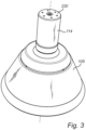
- the sleeve 114 is mounted around the uppermost end 117 of shaft 107.
- the cover 220 is centred around the axis 115. Accordingly, sleeve 114 is fully mated in position over conical shaft region 113 when the cover 220 is seated against shaft end 117 and the upper end 208 of the sleeve.
- the cover 220 helps the sleeve 114 to stay closely connected to the upper end shaft region 113 while the crusher is operating.
- the upper end shaft region 113 is enveloped laterally by the sleeve 114.
- the sleeve has a wall thickness 203.
- the inner surface of the sleeve 114 is in direct contact with the external facing surface 202 of the upper end shaft region 113.
- the cover 220 is in direct contact with the upper end shaft region 113 and the sleeve 114, centred around axis 115.
- the outer perimeter of the cover is slightly tapered outwardly from the top to the lower end, so that the lower end of the cover 220, which is in contact with the upper end shaft region 113 and the sleeve 114, has the same diameter as the sleeve upper end 208.
- Both the upper end shaft region 113 external facing surface 202 and the sleeve 114 internal facing surface 200 are tapered throughout the axial length.
- the internal surface 200 of the sleeve 114 has a section 210 in the axial direction with an upper end 210a and a lower end 210b.
- the sleeve section 210 from the upper end 210a to the lower end 210b has a section tapering angle ⁇ between the internal surface and an imaginary axis 125 that is different from the sleeve angle ⁇ defining the tapering of the sleeve from the sleeve upper end 208 to the section upper end 210a between the internal surface 200 and the imaginary axis 125.
- the imaginary axis 125 is parallel with the centre axis 115 and passes through the sleeve section upper end 210a.
- the angle ⁇ is smaller than the angle ⁇ .
- the sleeve section 210 is arranged close to the first lower end 207 of the sleeve. Thus, the sleeve section is located below the bearing assembly 112 of the crusher.
- Figure 4a discloses a first embodiment having a tapered shaft 113 and sleeve 114.
- the main shaft 107 tapered region 113 has a shaft section 209.
- This shaft section 209 is defined by an upper end 209a and a lower end 209b
- the sleeve section 210 is defined by an upper end 210a and a lower end 210b.
- both sections 209, 210 are arranged closely together, so that their upper ends 209a, 210a and their lower ends 209b, 210b are located at approximately the same axial location.
- both the sleeve and the shaft sections 209, 210 are cylindrical. Both sections 209, 210 are devoid of any tapering along their axial lengths, so that the diameter of the shaft is uniform along the shaft section 209 and the thickness of the wall 203 is uniform along the sleeve section 210.
- the full axial length of the sleeve 114 from the first lower end 207 to the second upper end 208 is defined as L1.
- the axial length of the sleeve section 210 from the upper 210a to the lower end 210b is L2.
- the axial length L3 of the lower curved or sharp tapered edge region is the length from the lower end sleeve section 210b to the sleeve lower end 207.
- L2 and L3 have approximately the same lengths.
- the axial length of the cylindrical shaft section 209 being the length from the upper end shaft section 209a to the lower end shaft section 209b, is defined as L4.
- L4 is approximately the same as the axial length L2 of the cylindrical sleeve section 210, such that both sections 209, 210 correspondingly mate.
- L2 and L4 may be longer than L3, they may be twice as long or less.
- a radius Rc at the upper end 208 of the sleeve is defined from the centre axis 115 to the internal surface 200. Further down of the sleeve the radius increases, so the radius Ra at the section upper end 210a is larger than radius Rc.
- the radius Rb at the sleeve lower end 210b is either slightly larger than Ra, as can be seen in figure 4a , where the angle ⁇ is larger than 0, or corresponds to Ra, as can be seen in figure 4b where the angle ⁇ is equal 0.
- the axial wall 203 comprises a thickness that decreases from upper end 208 to lower end 207 over the entire length of sleeve 114.
- the thickness decrease is uniform from the second upper end 208 to the upper end 210a of the cylindrical sleeve section 210.
- this section has an angle ⁇ being smaller than the angle ⁇ .
- this section has a uniform wall thickness with the angle ⁇ being 0.
- the end region 204 may also be curved.
- the sharp tapered region has an angle ⁇ being the angle between the internal surface 200 at the end region 204 and the imaginary axis 125. The angle ⁇ is larger than both angle ⁇ and angle ⁇ .
- the cap 220 When disassembling the crusher for maintenance or repair, the cap 220 is removed by first removing the fastening means, such as screws keeping the cap secured to the shaft 114. After having removed the cap the sleeve 114 can be dismounted.
Description
- The present invention relates to a gyratory crusher main shaft sleeve for positioning at an uppermost tapered end of a crusher main shaft and in particular, to a gyratory crusher main shaft.
- Gyratory crushers are used for crushing ore, mineral and rock material to smaller sizes. Typically, the crusher comprises a crushing head mounted upon an elongate main shaft. A first crushing shell is mounted on the crushing head and a second crushing shell is mounted on a frame such that the first and second crushing shells define together a crushing gap through which the material to be crushed is passed. A driving device is arranged to rotate an eccentric assembly about the lower portion of the shaft, so as to cause the crushing head to perform a gyratory pendulum movement and crush the material introduced in the crushing gap.
-
- In gyratory crushers the gyratory pendulum movement of the crushing head is supported by a lower bearing assembly positioned below the crushing head and a top bearing into which an upper end of the main shaft is journaled. Typically, the main shaft upper end is protected against wear by a sleeve. Commonly, the protective sleeve comprises a cylindrical geometry and is held at the main shaft via an interference or friction fit. This arrangement requires the sleeve to be heated to increase its diameter to enable mounting and possible disassembly at the main shaft.
- However, a number of problems exist with conventional protective sleeves. In particular, assembling and re-assembling of crushers when the sleeve is changed due to wear may be both time consuming and require a great amount of material. When changing the sleeve due to excessive wear or if reshaping of the sleeve is needed both the sleeve and the shaft need to be worked on to get proper surfaces for assembling the sleeve. On large crushers, protective sleeves have a substantial wall thickness with a great difference in material thickness between lower and upper parts. It is not unusual that the lower thinner end will be damaged, i.e. bent or even broken. Thus, what is required is a main shaft sleeve that addresses the above problems.
- It is an object of the present invention to provide a sleeve for a main shaft of a gyratory crusher that enables convenient attachment and detachment at the shaft so as to be quickly and conveniently assembled and disassembled. Further there is an object to save material and avoid that the lower and thinner part of the sleeve is bent or broken. Another object is to secure the sleeve and shaft stay correctly in place while operating.
- The objective is achieved by providing a sleeve having an internal facing surface that tapers inwardly in the axial direction towards an axis of the sleeve from a first lower end to a second upper end. The present sleeve arrangement is configured for secure mounting in position via an interference or friction fit arrangement in direct contact with a tapered end region of the main shaft. In particular, a conical shape profile of the internal facing surface of the sleeve having a section with a different conical shape profile than the rest of the sleeve is capable of sliding over a corresponding conical shaped main shaft end region efficiently guides the sleeve in place when being mated. As with existing devices, the present sleeve may be heated to increase its diameter immediately prior to assembly.
- Similarly, to facilitate disassembly, heat may be applied to the sleeve together with mechanical agitation.
- According to a first aspect of the present invention there is provided a gyratory crusher main shaft sleeve for friction fitting over an uppermost tapered end of a crusher main shaft, the sleeve comprising: an elongate axial wall from an upper end to a lower end extending and being centred around a centre axis and having an external facing surface and an internal facing surface aligned transverse to taper inwardly towards the axis, and wherein the tapering is defined by a sleeve tapering angle between the internal facing surface and an imaginary axis being parallel with the axis. The internal surface of the sleeve has a section in axial direction with an upper end and a lower end, which sleeve section from the upper end to the lower end has a section tapering angle between the internal surface and the imaginary axis being different compared to the sleeve angle defining the tapering of the sleeve from the sleeve upper end to the section upper end. This facilitates assembling and disassembling.
- The section angle of the sleeve section is smaller than the sleeve angle of the sleeve. Thus, the sleeve section is less tapered than the part of the sleeve above the section. A shape profile of the internal facing surface of the sleeve may define a section of a cone in the axial direction, so that the conical angle of the sleeve following the internal surface from the sleeve upper end changes when reaching the section upper end. Whereby a more robust lower end that hinders breakage is achieved.
- Optionally, the sleeve section is arranged close to the first lower end of the sleeve, so that the sleeve section is located below the bearing assembly. The wall thickness of the sleeve may decrease in a direction from the upper end to the lower end, and at the sleeve section the wall thickness may decrease to a lower extent so that material is saved.
- Preferably, the sleeve section lower end is arranged in connection to a lower sharp tapered edge region with an axial length and being the lowest part of the sleeve connecting to the first lower end. Alternatively, this lowest part of the sleeve may have a curved edge region. This region may be curved radially outward relative to the longitudinal axis in a direction towards the external facing surface of the sleeve such that the wall thickness decreases to zero at the curved region.
- Optionally, the length from the sleeve section upper end to the sleeve section lower end is approximately 10% of the total axial length of the sleeve. The length from the sleeve section upper end to the sleeve section lower end may also be 8%, 9%, 11% or 12% of the total axial length of the sleeve.
- Also, the length from the sleeve section upper end to the sleeve section lower end is approximately 13% of the axial length of the internal surface from the sleeve upper end to the section lower end. This length may be defined as the difference between the total axial length of the sleeve and the axial length of the sharp tapered edge region and it may also be in the ranges 10-12% or 14-17%.
- Preferably, the sleeve section is cylindrical in a circumferential direction of the internal facing surface such that the value of the section angle is 0 along the sleeve section. The thickness of the wall may then be uniform along the sleeve section and the thickness of the wall along the full axial length of the sleeve may decrease in a direction from a second upper end to a first lower end.
- Optionally, the axial length of the sleeve section is approximately the same as the axial length of the lower sharp tapered edge region.
- Preferably, a cross sectional shape profile of the external facing surface of the sleeve is substantially circular. Also, a cross sectional shape profile of the internal facing surface of the sleeve is substantially circular. And a shape profile of the external facing surface of the sleeve defines a section of a cylinder in the axial direction.
- According to a second aspect of the present invention there is provided a gyratory crusher main shaft comprising: an elongate shaft body having a first lower end for positioning at a lower region of the crusher and a second upper end for positioning at an upper region of the crusher relative to the first end, wherein an axial region of the shaft body extending from the upper end is tapered longitudinal relative to a centre axis of the shaft body such that a cross sectional area of the shaft body at the tapered region decreases in a direction from the first lower end to the second upper end, the tapered region configured to mount a shaft sleeve, and wherein the tapering is defined by a shaft tapering angle between the outward facing surface and an imaginary axis being parallel with the axis; and the main shaft further comprises a sleeve as described herein such that the sleeve is positioned in contact with an outward facing surface at the main shaft tapered region.
- Preferably, the main shaft tapered region has a shaft section in axial direction with an upper end and a lower end, which shaft section from the upper end to the lower end has a section tapering angle between the outward facing surface and the axis being different compared to the sleeve angle defining the tapering of the shaft from the shaft upper end to the section upper end.
- Optionally, the axial length of the cylindrical shaft section is the same as the axial length of the cylindrical sleeve section such that both sections correspondingly mate.
- Preferably, the main shaft further is connected to a cap arranged in close contact at the upper end in order to keep the sleeve safely arranged around the axial region of the shaft body. The cap may also be defined as a cover or a lid.
- Optionally, the thickness of the cap is half of the thickness of the wall at the upper end. The cap may also be tapered around the perimeter such that the diameter on the cap upper end is smaller than the diameter on the lower end connecting to and corresponding to the diameter of the upper end of the external surface of the sleeve. This ensures sleeve and shaft staying in place tightly together while the cruusher is operating.
- Preferably, the thickness of the wall decreases substantially the full axial length of the sleeve such that the wall thickness at the upper end is approximately 20% of the radius of the main shaft tapered region in the cross section area at the upper end and the wall thickness of the sleeve at the sections is approximately 10% of the radius of the main shaft tapered region in the cross section area at the sections. The wall thickness at the upper end may also be in the range 20-25% of the radius of the main shaft tapered region in the cross section area at the upper end, and the wall thickness of the sleeve at the sections may be 10-15% of the radius of the main shaft tapered region in the cross section area at the sections.
- According to a third aspect of the present invention there is provided a gyratory crusher comprising a main shaft and a sleeve.
- A specific implementation of the present invention will now be described by way example only and with reference to the following drawings in which:
-
Figure 1 is a cross-sectional side view of a gyratory crusher having a main shaft supported at its upper end by a top bearing set and having a protective sleeve mounted about the upper end of the main shaft; -
Figure 2 is a magnified view of the upper region of the crusher offigure 1 ; -
Figure 3 is a perspective view of the main shaft with the sleeve; -
Figure 4a is a cross-sectional side view of a first embodiment of the main shaft with the sleeve; -
Figure 4b is a cross-sectional side view of a second embodiment of the main shaft with the sleeve; -
Figure 5 is a cross-sectional side view of the sleeve. - Referring to
figure 1 , a crusher comprises aframe 100 having anupper frame 101 and alower frame 102. A crushinghead 103 is mounted upon anelongate shaft 107. A first crushingshell 105 is fixably mounted on crushinghead 103 and a secondcrushing shell 106 is fixably mounted attop frame 101. A crushingzone 104 is formed between the opposed crushingshells discharge zone 109 is positioned immediately below crushingzone 104 and is defined, in part, bylower frame 102. -
Upper frame 101 is further divided into atop shell 111, mounted upon lower frame 102 (alternatively termed a bottom shell), and a spider that extends fromtop shell 111 and represents an upper portion of the crusher. The spider comprises two diametricallyopposed arms 110 that extend radially outward from a central cover positioned on alongitudinal axis 115 extending throughframe 100 and the gyratory crusher generally.Arms 110 are attached to an upper region oftop shell 111 via an intermediate annular flange that is centred aroundlongitudinal axis 115. Typically,arms 110 andtop shell 111 form a unitary structure and are formed integrally. - A drive (not shown) is coupled to
main shaft 107 via adrive shaft 108 andsuitable gearing 116 so as to rotateshaft 107 eccentrically aboutlongitudinal axis 115 and to cause crushinghead 103 to perform a gyratory pendulum movement and crush material introduced into crushinggap 104. An upper end region of ashaft 113 comprises an axial taper to define an upper conical section. The upper conical section tapers inwardly in the bottom to top direction away fromhead 103. Anuppermost end 117 ofshaft 107 is maintained in an axially rotatable position by atop bearing assembly 112. Similarly, abottom end 118 ofshaft 107 is supported by abottom bearing assembly 119. - To avoid excessive wear of the upper
conical portion 113, a substantiallycylindrical wear sleeve 114 is mounted over and aboutshaft region 113.Sleeve 114 is held in position atregion 113 by an interference or friction fit and is provided in close touching contact over the axial length of the upperconical portion 113. Accordingly,sleeve 114 is positioned intermediate between bearingassembly 112 andregion 113 to absorb the radial and axial loading forces resultant from the crushing action of the gyratory pendulum movement. - With reference to
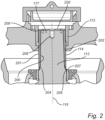
figure 2 ,sleeve 114 comprises an external facingsurface 201 and an internal facingsurface 200, the orientation offaces longitudinal axis 115 extending through upperend shaft region 113 andsleeve 114. -
Internal facing surface 200 is secured in direct contact against an external facingsurface 202 ofconical region 113. Accordingly, internal facingsurface 200 tapers inwardly towardslongitudinal axis 115 from afirst end 207 and asecond end 208, where thefirst end 207 is positioned belowsecond end 208 within the crusher during normal use. A cross-sectional shape profile of internal facingsurface 200 and external facingsurface 201 is circular substantially along the length ofsleeve 114 between first and second ends 207, 208. However, external facingsurface 201 is aligned substantially parallel withaxis 115, such thatsleeve 114 when viewed externally comprises a substantially cylindrical geometry. According to this configuration, the annularaxial wall 203 ofsleeve 114 that is defined betweenopposed surfaces upper end 208 to firstlower end 207. As will be appreciated, to enablesleeve 114 to fit in close shrink-fit contact withconical end portion 113, the taper angle ofinner surface 200 is substantially equal to the taper angle of the external facingsurface 202 of upperend shaft region 113 relative toaxis 115. - At first
lower end 207, a thickness ofwall 203 decreases sharply as internal facingsurface 200 is sharply tapered or curves outwardly toward external facingsurface 201. This curved or sharp taperedannular edge region 204 is configured to fit against ashoulder region 205 ofshaft 107 that curves radially outward at a region immediately above crushingshell 105 andhead 103. -
Uppermost end 117 ofshaft 107 is retained in position by a mountingpin 206, aligned ataxis 115, that extends axially downward from acircular cover 220. -
Figure 3 discloses a perspective view of the first crushingshell 105 mounted upon theelongate shaft 107. Thesleeve 114 is mounted around theuppermost end 117 ofshaft 107. On top of theuppermost end 117 ofshaft 107 thecover 220 is centred around theaxis 115. Accordingly,sleeve 114 is fully mated in position overconical shaft region 113 when thecover 220 is seated againstshaft end 117 and theupper end 208 of the sleeve. Thecover 220 helps thesleeve 114 to stay closely connected to the upperend shaft region 113 while the crusher is operating. - With reference to
figures 4a and4b , the upperend shaft region 113 is enveloped laterally by thesleeve 114. The sleeve has awall thickness 203. The inner surface of thesleeve 114 is in direct contact with the external facingsurface 202 of the upperend shaft region 113. Thecover 220 is in direct contact with the upperend shaft region 113 and thesleeve 114, centred aroundaxis 115. The outer perimeter of the cover is slightly tapered outwardly from the top to the lower end, so that the lower end of thecover 220, which is in contact with the upperend shaft region 113 and thesleeve 114, has the same diameter as the sleeveupper end 208. Both the upperend shaft region 113 external facingsurface 202 and thesleeve 114 internal facingsurface 200 are tapered throughout the axial length. - The
internal surface 200 of thesleeve 114 has asection 210 in the axial direction with anupper end 210a and alower end 210b. Thesleeve section 210 from theupper end 210a to thelower end 210b has a section tapering angle α between the internal surface and animaginary axis 125 that is different from the sleeve angle γ defining the tapering of the sleeve from the sleeveupper end 208 to the sectionupper end 210a between theinternal surface 200 and theimaginary axis 125. Theimaginary axis 125 is parallel with thecentre axis 115 and passes through the sleeve sectionupper end 210a. For example, the angle α is smaller than the angle γ. - The
sleeve section 210 is arranged close to the firstlower end 207 of the sleeve. Thus, the sleeve section is located below the bearingassembly 112 of the crusher. -
Figure 4a discloses a first embodiment having a taperedshaft 113 andsleeve 114. Themain shaft 107 taperedregion 113 has ashaft section 209. Thisshaft section 209 is defined by anupper end 209a and alower end 209b, and thesleeve section 210 is defined by anupper end 210a and alower end 210b. When the upperend shaft region 113 and thesleeve 114 are mated together bothsections upper ends lower ends - With reference to
figure 4b , disclosing a second embodiment, the tapering of the upperend shaft region 113 external facingsurface 202 and thesleeve 114 internal facingsurface 200 is disrupted at theshaft section 209 and thesleeve section 210. Both the sleeve and theshaft sections sections shaft section 209 and the thickness of thewall 203 is uniform along thesleeve section 210. - Further with reference to
figures 4a ,4b and5 , the full axial length of thesleeve 114 from the firstlower end 207 to the secondupper end 208 is defined as L1. The axial length of thesleeve section 210 from the upper 210a to thelower end 210b is L2. The axial length L3 of the lower curved or sharp tapered edge region is the length from the lowerend sleeve section 210b to the sleevelower end 207. L2 and L3 have approximately the same lengths. The axial length of thecylindrical shaft section 209, being the length from the upperend shaft section 209a to the lowerend shaft section 209b, is defined as L4. L4 is approximately the same as the axial length L2 of thecylindrical sleeve section 210, such that bothsections - Further, the tapering of the
internal surface 200 of the sleeve will be described. A radius Rc at theupper end 208 of the sleeve is defined from thecentre axis 115 to theinternal surface 200. Further down of the sleeve the radius increases, so the radius Ra at the sectionupper end 210a is larger than radius Rc. The radius Rb at the sleevelower end 210b is either slightly larger than Ra, as can be seen infigure 4a , where the angle α is larger than 0, or corresponds to Ra, as can be seen infigure 4b where the angle α is equal 0. - The
axial wall 203 comprises a thickness that decreases fromupper end 208 tolower end 207 over the entire length ofsleeve 114. The thickness decrease is uniform from the secondupper end 208 to theupper end 210a of thecylindrical sleeve section 210. In thesleeve section 210 seen infigure 4a , there is less decrease of the thickness, since this section has an angle α being smaller than the angle γ. In thesleeve section 210 seen infigure 4b , there is no decrease, since this section has a uniform wall thickness with the angle α being 0. - From the
lower end 210b of thecylindrical sleeve section 210 to thelower end 207 of the sleeve theaxial wall 203 thickness decreases more than the decrease in thickness from the sleeveupper end 208 to the cylindrical sectionupper end 210a, resulting in a sharptapered end region 204. Theend region 204 may also be curved. The sharp tapered region has an angle β being the angle between theinternal surface 200 at theend region 204 and theimaginary axis 125. The angle β is larger than both angle α and angle γ. - When disassembling the crusher for maintenance or repair, the
cap 220 is removed by first removing the fastening means, such as screws keeping the cap secured to theshaft 114. After having removed the cap thesleeve 114 can be dismounted.
Claims (14)
- A gyratory crusher main shaft sleeve (114) for friction fitting over an uppermost tapered end (113) of a crusher main shaft (107), the sleeve comprising:an elongate axial wall (203) from an upper end (208) to a lower end (207) extending and being centred around a centre axis (115) and having an external facing surface (201) and an internal facing surface (200) aligned transverse to taper inwardly towards the axis (115), and wherein the tapering is defined by a sleeve tapering angle (γ) between the internal facing surface (200) and an imaginary axis (125) being parallel with the axis (115);and wherein the internal surface (200) of the sleeve (114) has a section (210) in axial direction with an upper end (210a) and a lower end (210b), which sleeve section (210) from the upper end (210a) to the lower end (210b) has a section tapering angle (α) between the internal surface and the imaginary axis (125) being different compared to the sleeve angle (γ) defining the tapering of the sleeve from the sleeve upper end (208) to the section upper end (210a),characterized in that, the section angle (α) of the sleeve section (210) is smaller than the sleeve angle (γ) of the sleeve (114).
- The sleeve as claimed in claim 1, wherein the sleeve section (210) is arranged close to the first lower end (207) of the sleeve (114).
- The sleeve as claimed in any preceding claim, wherein the sleeve section lower end (210b) is arranged in connection to a lower sharp tapered edge region (204) with an axial length (L3) and being the lowest part of the sleeve (114) connecting to the first lower end (207).
- The sleeve as claimed in any preceding claim, wherein the length (L2) from the sleeve section upper end (210a) to the sleeve section lower end (210b) is approximately 10% of the total axial length (L1) of the sleeve (114).
- The sleeve as claimed in any preceding claim, wherein the length (L2) from the sleeve section upper end (210a) to the sleeve section lower end (210b) is approximately 13% of the axial length of the internal surface (200) from the sleeve upper end (208) to the section lower end (210b).
- The sleeve as claimed in any preceding claim, wherein the sleeve section (210) is cylindrical in a circumferential direction of the internal facing surface (200) such that the value of the section angle (α) is 0 along the sleeve section (210).
- The sleeve as claimed in any preceding claim, wherein the axial length (L2) of the sleeve section (210) is approximately the same as the axial length (L3) of the lower sharp tapered edge region (204).
- A gyratory crusher main shaft comprising:an elongate shaft body having a first lower end (118) for positioning at a lower region of the crusher and a second upper end (117) for positioning at an upper region of the crusher relative to the first end (118), wherein an axial region (113) of the shaft body extending from the upper end (117) is tapered longitudinal relative to a centre axis (115) of the shaft body such that a cross sectional area of the shaft body at the tapered region (113) decreases in a direction from the first lower end (118) to the second upper end (117), the tapered region (113) is configured to mount a shaft sleeve (114), and wherein the tapering is defined by a shaft tapering angle (γ) between the outward facing surface (202) and an imaginary axis (125) being parallel with the axis (115); andthe main shaft further comprises a sleeve (114) as claimed in any preceding claim friction fitted over the tapered region (113) at the upper end (117) of the main shaft such that the sleeve is positioned in contact with an outward facing surface (202) at the main shaft tapered region (113),characterized in that, the main shaft (107) tapered region (113) has a shaft section (209) in axial direction with an upper end (209a) and a lower end (209b), which shaft section (209) from the upper end (209a) to the lower end (209b) has a section tapering angle (α) between the outward facing surface (202) and the axis (115) being different compared to the sleeve angle (γ) defining the tapering of the shaft from the shaft upper end (117) to the section upper end (209a).
- The main shaft as claimed in claim 8, wherein the axial length (L4) of the cylindrical shaft section (209) is the same as the axial length (L2) of the cylindrical sleeve section (210) such that both sections (209, 210) correspondingly mate.
- The main shaft as claimed in any of claims 8 to 9, wherein the main shaft further is connected to a cap (220) arranged in close contact at the upper end (117) in order to keep the sleeve (114) safely arranged around the axial region (113) of the shaft body.
- The main shaft as claimed in claim 10 wherein the thickness of the cap (220) is half of the thickness of the wall at the upper end.
- The main shaft as claimed in claims 10 or 11, wherein the cap (220) is tapered around the perimeter such that the diameter on the cap upper end is smaller than the diameter on the lower end connecting to and corresponding to the diameter of the upper end (208) of the external surface (201) of the sleeve (114).
- The main shaft as claimed in any of claims 8 to 12, wherein the thickness of the wall (203) decreases substantially the full axial length of the sleeve (114) such that the wall thickness at the upper end (208) is approximately 20% of the radius of the main shaft (107) tapered region (113) in the cross section area at the upper end and the wall thickness of the sleeve at the sections (209, 210) is approximately 10% of the radius of the main shaft (107) tapered region (113) in the cross section area at the sections (209, 210).
- A gyratory crusher comprising a main shaft (107) and a sleeve (114) as claimed in any of claims 8 to 13.
Applications Claiming Priority (1)
| Application Number | Priority Date | Filing Date | Title |
|---|---|---|---|
| PCT/EP2018/076660 WO2020069719A1 (en) | 2018-10-01 | 2018-10-01 | Gyratory crusher main shaft sleeve |
Publications (2)
| Publication Number | Publication Date |
|---|---|
| EP3860762A1 EP3860762A1 (en) | 2021-08-11 |
| EP3860762B1 true EP3860762B1 (en) | 2023-12-06 |
Family
ID=63722398
Family Applications (1)
| Application Number | Title | Priority Date | Filing Date |
|---|---|---|---|
| EP18782042.8A Active EP3860762B1 (en) | 2018-10-01 | 2018-10-01 | Gyratory crusher main shaft sleeve |
Country Status (6)
| Country | Link |
|---|---|
| US (1) | US20210402410A1 (en) |
| EP (1) | EP3860762B1 (en) |
| CN (1) | CN112789116B (en) |
| AU (1) | AU2018444291A1 (en) |
| CA (1) | CA3113474A1 (en) |
| WO (1) | WO2020069719A1 (en) |
Families Citing this family (1)
| Publication number | Priority date | Publication date | Assignee | Title |
|---|---|---|---|---|
| CN112756042B (en) * | 2020-12-31 | 2022-06-10 | 金堆城钼业股份有限公司 | Fixing method for crossbeam bushing of single-cylinder hydraulic cone crusher |
Family Cites Families (9)
| Publication number | Priority date | Publication date | Assignee | Title |
|---|---|---|---|---|
| US1402255A (en) | 1918-02-18 | 1922-01-03 | Smith Engineering Works | Crusher |
| GB1031679A (en) | 1963-12-12 | 1966-06-02 | Franca Ghiazza | Improved gyratory crushing machine |
| US6468194B2 (en) * | 2000-12-08 | 2002-10-22 | Morgan Construction Company | Sleeve for rolling mill oil film bearing |
| US7267490B2 (en) * | 2001-12-21 | 2007-09-11 | Ntn Corporation | Bearing apparatus for a driving wheel of vehicle |
| EP2689851A1 (en) * | 2012-07-27 | 2014-01-29 | Sandvik Intellectual Property AB | Gyratory crusher bearing |
| EP2692444A1 (en) * | 2012-08-02 | 2014-02-05 | Sandvik Intellectual Property AB | Gyratory crusher main shaft sleeve |
| EP2870999B1 (en) * | 2013-11-12 | 2016-02-03 | Sandvik Intellectual Property AB | Gyratory crusher main shaft and assembly |
| EP2873461B1 (en) * | 2013-11-19 | 2017-04-12 | Sandvik Intellectual Property AB | A gyratory crusher spider bushing assembly |
| CN206106811U (en) * | 2016-10-20 | 2017-04-19 | 江西海峰重工科技有限责任公司 | Automobile drive axle semi -axis sleeve pipe |
-
2018
- 2018-10-01 WO PCT/EP2018/076660 patent/WO2020069719A1/en active Application Filing
- 2018-10-01 CN CN201880098258.6A patent/CN112789116B/en active Active
- 2018-10-01 EP EP18782042.8A patent/EP3860762B1/en active Active
- 2018-10-01 AU AU2018444291A patent/AU2018444291A1/en active Pending
- 2018-10-01 CA CA3113474A patent/CA3113474A1/en active Pending
- 2018-10-01 US US17/281,318 patent/US20210402410A1/en active Pending
Also Published As
| Publication number | Publication date |
|---|---|
| AU2018444291A1 (en) | 2021-04-15 |
| CA3113474A1 (en) | 2020-04-09 |
| CN112789116A (en) | 2021-05-11 |
| WO2020069719A1 (en) | 2020-04-09 |
| US20210402410A1 (en) | 2021-12-30 |
| CN112789116B (en) | 2023-01-17 |
| EP3860762A1 (en) | 2021-08-11 |
Similar Documents
| Publication | Publication Date | Title |
|---|---|---|
| US9827568B2 (en) | Gyratory crusher main shaft sleeve | |
| EP2647438B1 (en) | Gyratory crusher frame | |
| EP3860762B1 (en) | Gyratory crusher main shaft sleeve | |
| EP2774680B1 (en) | Gyratory crusher outer crushing shell | |
| US20140252151A1 (en) | Gyratory crusher outer crushing shell | |
| EP2647439B1 (en) | Gyratory crusher frame | |
| RU2773036C1 (en) | Gyrational crusher main shaft bushing | |
| EP2692442A1 (en) | Gyratory crusher outer crushing shell | |
| EP3746227B1 (en) | Gyratory crusher topshell | |
| AU2013242873B2 (en) | Gyratory crusher crushing head | |
| EP3746228B1 (en) | Gyratory crusher bottomshell with inspection hatch assembly | |
| EP4108334A1 (en) | Bolting assembly for cone crusher | |
| US6520438B2 (en) | Gyratory crusher mainshaft |
Legal Events
| Date | Code | Title | Description |
|---|---|---|---|
| STAA | Information on the status of an ep patent application or granted ep patent |
Free format text: STATUS: UNKNOWN |
|
| STAA | Information on the status of an ep patent application or granted ep patent |
Free format text: STATUS: THE INTERNATIONAL PUBLICATION HAS BEEN MADE |
|
| PUAI | Public reference made under article 153(3) epc to a published international application that has entered the european phase |
Free format text: ORIGINAL CODE: 0009012 |
|
| STAA | Information on the status of an ep patent application or granted ep patent |
Free format text: STATUS: REQUEST FOR EXAMINATION WAS MADE |
|
| 17P | Request for examination filed |
Effective date: 20210503 |
|
| AK | Designated contracting states |
Kind code of ref document: A1 Designated state(s): AL AT BE BG CH CY CZ DE DK EE ES FI FR GB GR HR HU IE IS IT LI LT LU LV MC MK MT NL NO PL PT RO RS SE SI SK SM TR |
|
| DAV | Request for validation of the european patent (deleted) | ||
| DAX | Request for extension of the european patent (deleted) | ||
| GRAP | Despatch of communication of intention to grant a patent |
Free format text: ORIGINAL CODE: EPIDOSNIGR1 |
|
| STAA | Information on the status of an ep patent application or granted ep patent |
Free format text: STATUS: GRANT OF PATENT IS INTENDED |
|
| INTG | Intention to grant announced |
Effective date: 20230511 |
|
| P01 | Opt-out of the competence of the unified patent court (upc) registered |
Effective date: 20230603 |
|
| GRAS | Grant fee paid |
Free format text: ORIGINAL CODE: EPIDOSNIGR3 |
|
| GRAA | (expected) grant |
Free format text: ORIGINAL CODE: 0009210 |
|
| STAA | Information on the status of an ep patent application or granted ep patent |
Free format text: STATUS: THE PATENT HAS BEEN GRANTED |
|
| AK | Designated contracting states |
Kind code of ref document: B1 Designated state(s): AL AT BE BG CH CY CZ DE DK EE ES FI FR GB GR HR HU IE IS IT LI LT LU LV MC MK MT NL NO PL PT RO RS SE SI SK SM TR |
|
| REG | Reference to a national code |
Ref country code: GB Ref legal event code: FG4D |
|
| REG | Reference to a national code |
Ref country code: CH Ref legal event code: EP |
|
| REG | Reference to a national code |
Ref country code: DE Ref legal event code: R096 Ref document number: 602018062249 Country of ref document: DE |
|
| REG | Reference to a national code |
Ref country code: IE Ref legal event code: FG4D |
|
| REG | Reference to a national code |
Ref country code: SE Ref legal event code: TRGR |
|
| REG | Reference to a national code |
Ref country code: LT Ref legal event code: MG9D |
|
| PG25 | Lapsed in a contracting state [announced via postgrant information from national office to epo] |
Ref country code: GR Free format text: LAPSE BECAUSE OF FAILURE TO SUBMIT A TRANSLATION OF THE DESCRIPTION OR TO PAY THE FEE WITHIN THE PRESCRIBED TIME-LIMIT Effective date: 20240307 |
|
| REG | Reference to a national code |
Ref country code: NL Ref legal event code: MP Effective date: 20231206 |
|
| PG25 | Lapsed in a contracting state [announced via postgrant information from national office to epo] |
Ref country code: LT Free format text: LAPSE BECAUSE OF FAILURE TO SUBMIT A TRANSLATION OF THE DESCRIPTION OR TO PAY THE FEE WITHIN THE PRESCRIBED TIME-LIMIT Effective date: 20231206 |