EP2873461B1 - A gyratory crusher spider bushing assembly - Google Patents
A gyratory crusher spider bushing assembly Download PDFInfo
- Publication number
- EP2873461B1 EP2873461B1 EP13193474.7A EP13193474A EP2873461B1 EP 2873461 B1 EP2873461 B1 EP 2873461B1 EP 13193474 A EP13193474 A EP 13193474A EP 2873461 B1 EP2873461 B1 EP 2873461B1
- Authority
- EP
- European Patent Office
- Prior art keywords
- collar
- main body
- assembly
- facing surface
- bushing
- Prior art date
- Legal status (The legal status is an assumption and is not a legal conclusion. Google has not performed a legal analysis and makes no representation as to the accuracy of the status listed.)
- Active
Links
Images


Classifications
-
- B—PERFORMING OPERATIONS; TRANSPORTING
- B02—CRUSHING, PULVERISING, OR DISINTEGRATING; PREPARATORY TREATMENT OF GRAIN FOR MILLING
- B02C—CRUSHING, PULVERISING, OR DISINTEGRATING IN GENERAL; MILLING GRAIN
- B02C2/00—Crushing or disintegrating by gyratory or cone crushers
- B02C2/02—Crushing or disintegrating by gyratory or cone crushers eccentrically moved
- B02C2/04—Crushing or disintegrating by gyratory or cone crushers eccentrically moved with vertical axis
- B02C2/06—Crushing or disintegrating by gyratory or cone crushers eccentrically moved with vertical axis and with top bearing
-
- B—PERFORMING OPERATIONS; TRANSPORTING
- B02—CRUSHING, PULVERISING, OR DISINTEGRATING; PREPARATORY TREATMENT OF GRAIN FOR MILLING
- B02C—CRUSHING, PULVERISING, OR DISINTEGRATING IN GENERAL; MILLING GRAIN
- B02C2/00—Crushing or disintegrating by gyratory or cone crushers
- B02C2/02—Crushing or disintegrating by gyratory or cone crushers eccentrically moved
- B02C2/04—Crushing or disintegrating by gyratory or cone crushers eccentrically moved with vertical axis
-
- F—MECHANICAL ENGINEERING; LIGHTING; HEATING; WEAPONS; BLASTING
- F16—ENGINEERING ELEMENTS AND UNITS; GENERAL MEASURES FOR PRODUCING AND MAINTAINING EFFECTIVE FUNCTIONING OF MACHINES OR INSTALLATIONS; THERMAL INSULATION IN GENERAL
- F16C—SHAFTS; FLEXIBLE SHAFTS; ELEMENTS OR CRANKSHAFT MECHANISMS; ROTARY BODIES OTHER THAN GEARING ELEMENTS; BEARINGS
- F16C17/00—Sliding-contact bearings for exclusively rotary movement
- F16C17/10—Sliding-contact bearings for exclusively rotary movement for both radial and axial load
Description
- The present invention relates to a gyratory crusher spider bushing assembly for positioning radially intermediate a topshell spider and a crusher main shaft.
- Gyratory crushers are used for crushing ore, mineral and rock material to smaller sizes. Typically, the crusher comprises a crushing head mounted upon an elongate main shaft. A first crushing shell is mounted on the crushing head and a second crushing shell is mounted on a frame such that the first and second crushing shells define together a crushing gap through which the material to be crushed is passed. A driving device is arranged to rotate an eccentric assembly about the lower portion of the shaft so as to cause the crushing head to perform a gyratory pendulum movement and crush the material introduced in the crushing gap.
- Typically, the main shaft is mounted at its upper end by a top bearing assembly in turn mounted within a spider. The main shaft and internal region of the spider are protected from wear via a sleeve that is typically friction fitted over the upper end of the main shaft and a floating spider bushing that protects the inward facing surface of the spider. Conventional sleeve and bushing assemblies are described in
US 1,110,887 ;US 1,748,102 ;US 2,598,548 ;US 4,060,205 andWO 2011/139210 . - Another sleeve and bushing assembly is for example described in
WO 94/17913 - It is an objective of the present invention to provide a spider bushing configured to protect the radially inner region of the topshell spider and that offers enhanced wear resistance over conventional bushings whilst minimising an amount of higher performance material forming a part of the bushing assembly. It is a further objective to provide a bushing assembly that is compatible for use with existing crushers and in particular topshell spiders without the need for modification of any surfaces, regions or additional components associated with mounting or stabilising the main shaft at its upper region within the spider. Accordingly, the inventors provide a bushing assembly having a general shape and configuration configured to match existing bushings that exhibits enhanced wear resistance in response to the gyroscopic precession of the main shaft within the crusher and in particular the central bore of the spider. The objectives are achieved by configuring the bushing as a multi-component assembly in which an annular main body (bushing) forms the majority component of the assembly and provides a mounting for a radially inner wear collar. Advantageously, the present collar is formed from or comprises a material that exhibits increased wear resistance relative to a material of the main body. The present assembly is particularly beneficial as the relative size, both with respect to the axial length and radial thickness of the collar is minimised relative to the main body such that a volume of the wear resistant material of the collar is maintained to a minimum. This is further achieved by the relative positioning of the collar at the main body such that the collar is configured to contact the main shaft (or protective main shaft sleeve) and avoid or minimise the touching contact between the main shaft and the main body of the bushing assembly.
- According to a first aspect of the present invention there is provided a gyratory crusher spider bushing assembly for positioning radially intermediate a topshell spider and a crusher main shaft configured for gyroscopic precession within a crusher, the assembly comprising: an annular main body extending around an axis of the assembly and having a radially outward facing surface for positioning opposed to the topshell spider and a radially inward facing surface for positioning opposed to the main shaft or a sleeve surrounding the main shaft, the main body formed from a first material; the main body comprising a first end having a mount flange extending radially outward and a second end intended to be positioned lowermost within the crusher relative to the first end; an annular wear collar positioned at the inward facing surface and extending radially inward from the main body to contact the main shaft or the sleeve; the collar mounted at the main body to prevent independent rotation of the collar about the axis relative to the main body; characterised in that: the collar comprises: a second material having a wear resistance greater than the first material; and an axial length corresponding to a distance between a first end and a second end of the collar that is less than that 75% of an axial length the main body corresponding to a distance between the first end of the main body and a region of the main body aligned at the same axial position as the second end of the collar; the collar positioned axially closest to the second end of the main body relative to the first end of the main body.
- Reference within the specification to the 'axial length of the main body' represents a distance in the axial direction between two regions of the main body and not necessarily a complete axial length of the main body as represented between an uppermost end surface and a lowermost end surface. Reference to an 'axial length of the main body' is a distance that is relative to a position and/or a distance in the axial direction of the annular wear collar or at least a part of the collar. Additionally, reference within the specification to an 'axial length of the collar' encompasses a total axial length of the collar between a first uppermost end surface and a second lowermost end surface, with the collar positioned within the bushing assembly and mounted within the crusher according to normal use. Advantageously, the axial length of the collar is appreciably less than the axial length of the main body to maintain to a minimum the volume of the collar and in particular the higher performance material of the collar that is utilised. The present bushing assembly is advantageous via the specific axial locking of the collar at the lowermost region of the bushing which is the region of contact between the bushing assembly and the main shaft (or intermediate main shaft sleeve). Accordingly, an axially upper region of the main body is devoid of the collar and hence the amount of higher performance material is minimised. Preferably, the axial length of the collar is less than 75% or 60% of an axial length of the main body. More preferably, the axial length of the collar is in the range 20% to 60% or 40% to 60% of the axial length of the main body. Preferably, the collar is positioned exclusively axially within a lower region of the main body closest to the second end relative to the first end such that an upper region of the main body closest to the first end is devoid of the collar. The majority of collar is positioned in a lower half of the main body to allow an axially upper region of the main body to taper radially outward to accommodate the gyroscopic movement of the main shaft and sleeve.
- The inward facing surface and/or the collar comprises a radially extending abutment to axially separate and prevent the collar from moving axially towards the first end. The abutment may be formed as one or a plurality of radial projections extending radially inward from the bushing and/or radially outward from the collar. Advantageously, the abutment is configured to prevent or inhibit axial upward movement of the collar relative to the bushing in response to the gyroscopic precession of the main shaft within the bushing assembly. That is, the abutment locks the collar at an axially lower position within the main body. Additionally, the collar may be attached to the main body via separate attachments that provide a radial lock of the collar at the main body. Optionally, the abutment comprises a step configuration at the inward facing surface of the main body. The step configuration may comprise a recess at the inward facing surface extending axially from the second end, the recess terminated at an axially upper region by an annular shoulder such that the collar is at least partially accommodated within the recess and the first end of the collar abuts the annular shoulder. The recess is advantageous to inhibit axial upward displacement of the collar relative to the main body. Optionally, the collar may be seated within the recess in direct contact with the radially inward facing surface of the main body. Alternatively, an intermediate sleeve or one or a plurality of mounting elements may be positioned radially between the collar and the main body (at the region of the recess) to provide correct seating and alignment of the collar relative to the main body and/or the main shaft or protective main shaft sleeve. Optionally, the collar may be biased radially inward by at least one biasing element positioned at the region of the groove and/or main body. Preferably, the inward facing surface at the recess is aligned substantially parallel with the axis and the inward facing surface of the main body axially between the first end and the recess is aligned transverse to the axis.
- The physical or mechanical properties of second material relative to the first material may comprises any one of a combination of: a material that has a higher hardness; a softer material having reduced friction or friction coefficient; a material that has a lower surface pressure. Advantageously, the wear resistant second material provides an increased time period between maintenance or service intervals. Within this specification the relative wear resistance of the first and second material refers, in part, to their abrasion characteristics and in particular the amount of material that would be removed through abrasion testing that may typically involve monitoring the volume of material removed from a test sample for a particular time interval when exposed to a grinder under standard control conditions including: temperature, applied force, speed of relative surface movement between the grinder and the sample body etc.
- Rotatably locking the collar at the main body such that the collar is prevented from independent rotation about the central axis relative to the main body is advantageous to avoid accelerated wear of the main body given the differences in the physical or mechanical properties (wear resistance) of the collar and the main body. Preferably, the assembly further comprises a plurality of attachment elements extending between the collar and the main body. Optionally, the attachment elements are aligned coaxially with the main body and/or the collar and are positioned axially at or towards the second end of the main body. Optionally, the attachment elements comprise bolts, screw, pins, rivets, interlocking flanges, tong and groove arrangements and the like. Where the attachment elements comprise bolts, screws or pins, the elements may be aligned coaxially with the main body and/or the collar. The attachment elements are advantageous to rotatably lock the collar to the main body of the bushing to prevent any wear of the bushing due to undesirable rotation of the collar whilst being accessible for convenient mounting and demounting the collar at the bushing assembly.
- Optionally, the collar may be friction fitted within the main body optionally via a thermal shrink-fitting process applied to the collar and/or a thermal expansion and contraction of the main body. Optionally, the collar may be held at the main body exclusively by friction forces created by the geometry and dimensions of the collar relative to the main body such that the collar may be oversized relative to the region of the main body with which it mates.
- Within the present assembly, the flange provides a means of mounting the assembly at the central boss of the spider optionally via a plurality of anchorage bolts or the like. The flange also prevents any axially downward movement of the bushing assembly.
- According to a specific implementation, the second end of the collar comprises a chamfer to decrease a radial thickness of the collar at the second end between an inward and an outward facing surface of the collar. The chamfer accordingly provides a smooth transition at the axially lower region of the assembly for mating against an annular sealing ring positioned at the axially lower second end.
- Preferably, the collar is positioned axially between the first and second ends of the main body such that the second end of the collar is axially separated from the second end of the main body. This is advantageous to create an annular cavity region at the second lowermost end of the main body to accommodate the sealing ring and lubrication oil.
- Preferably, a radial thickness of the main body between the inward and outward facing surfaces is greater than a radial thickness of the collar between a radially inward and radially outward facing surface of the collar. The radial thickness of the collar is maintained to a minimum to minimise the volume of the wear resistant material incorporated as part of the assembly.
- Optionally, the first material may comprise a metal, a polymer, a ceramic, a steel, a steel alloy or in particular grey iron. Optionally the second material comprises any one or a combination of the set of: a metal or metal alloy; a copper/zinc based alloy; a manganese steel; a polymer; a ceramic.
- The inward facing surface of the main body is aligned transverse to the axis of the assembly to tilt radially outward such that a radial separation distance of said inward facing surface at an axial position of the first end of the main body is more than a radial separation distance of said inward facing surface at an axial position at or towards the abutment.. The foot is advantageous to hook around an inner region of the annular sealing ring so as to maintain both the radial and axial position of the sealing ring relative to the main body, the spider boss and the main shaft and/or protective main shaft sleeve. According to a second aspect of the present invention there is provided a gyratory crusher comprising an assembly as claimed herein.
- A specific implementation of the present invention will now be described, by way of example only, and with reference to the accompanying drawings in which:
-
Figure 1 is a cross sectional side view of a gyratory crusher in which an upper end of a main shaft is seated at least partial within a spider via a spider bushing formed from a main body and an inner wear collar according to a specific implementation of the present invention; -
Figure 2 is a magnified perspective view of the spider bushing assembly offigure 1 positioned about the upper end of the main shaft; -
Figure 3 is a cross sectional side view of the spider bushing assembly offigure 2 positioned about the upper end of the main shaft; -
Figure 4 is a cross sectional side view of the spider bushing offigure 3 removed from the main shaft; -
Figure 5 is a magnified cross sectional view of a part of the spider bushing assembly offigure 4 ; -
Figure 6 is a lower perspective view of the magnified region of the spider bushing assembly offigure 5 . - Referring to
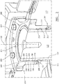
figure 1 , a crusher comprises aframe 100 having anupper frame 101 and alower frame 102. A crushinghead 103 is mounted upon anelongate shaft 107 havinglongitudinal axis 115. A first (inner) crushingshell 105 is fixably mounted on crushinghead 103 and a second (outer) crushingshell 106 is fixably mounted atupper frame 101. A crushingzone 104 is formed between the opposed crushingshells discharge zone 109 is positioned immediately below crushingzone 104 and is defined, in part, bylower frame 102. - A drive (not shown) is coupled to
main shaft 107 via adrive shaft 108 andsuitable gearing 116 so as to rotateshaft 107 eccentrically about alongitudinal axis 122 of the crusher and to causehead 103 andmantle 105 to perform a gyratory pendulum movement and crush material introduced into crushingzone 104. Accordingly thelongitudinal axis 115 ofmain shaft 107 oscillates about crusherlongitudinal axis 122. Anupper end region 113 ofshaft 107 is maintained in an axially rotatable position by a top-end bearing assembly and aspider bushing 112 positioned intermediate betweenmain shaft region 113 and acentral boss 117 positioned aboutaxis 122. Similarly, abottom end region 118 ofshaft 107 is supported by a bottom-end bearing assembly 119. -
Upper frame 101 comprises atopshell 111, mounted upon lower frame 102 (alternatively termed a bottom shell), and aspider assembly 110 that extends fromtopshell 111 and represents an upper portion of the crusher. Thespider 110 comprises two diametrically opposed arms that extend radially outward fromcentral boss 117. The spider arms are attached to an upper region oftopshell 111 via an intermediate annular flange such that the spider arms andtopshell 111 form a unitary structure and are formed integrally. - Upper
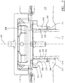
shaft end region 113 is protected and encased by anannular sleeve 114.Spider bushing 112 is positioned atcentral boss 117 to contact the radially outward facingsurface 204 ofsleeve 114 assleeve 114 rotates withincentral boss 117. Anannular wear collar 120 is mounted coaxially and radially intermediate an axially lower region ofbushing 112 andshaft sleeve 114 to provide a seat for therotating sleeve 114 that, due to the relative dimensions and positioning ofwear collar 120 is prevented from contact withbushing 112. This is advantageous to obviate the requirement for replacement of theentire bushing 112 which would otherwise wear due to the rotating frictional contact withsleeve 114.Collar 120 may be attached atbushing 112 via specific attachment elements as described herein or may be thermally shrink-fitted within thebushing 112. Accordingly, in some embodiments,collar 120 may be removed and replaced atbushing 112 when worn. Alternatively, the entire assembly may be designed to be replaced follow wear ofcollar 120. Additionally, it is advantageous forcollar 120 to comprise a different material to that ofbushing 112 so as to be optimised for wear resistance. As the general size and geometry ofcollar 120 is significantly less than bushing 112, the increased cost of the wear resistant material is maintained to a minimum which would otherwise be prohibitive if implemented as part of the muchlarger bushing 112. - Referring to
figures 2 to 6 ,bushing 112 comprises a generally annular sleeve-like body that extends aroundaxis 122 and is positioned centrally withinspider boss 117.Bushing 112 comprises a radially inward facingsurface 203 at an axially upper half and a corresponding radially inward facingsurface 201 at an axially lower half.Inner surface 201 is stepped radially outward fromaxis 122 relative toinner surface 203 to create anannular shoulder 210 at the inner region ofbushing 112 positioned approximately at a mid-axial region between a first axiallyupper end 208 and a second axiallylower end 207 ofbushing 112. An opposed radially outward facingsurface 215 ofbushing 112 is configured for contact and mating against a radially inward facingsurface 216 ofspider boss 117. The region between the outward facingsurface 215 and inward facing surfaces 201, 203 defines the annular wall ofbushing 112. Anannular flange 209 projects radially outward from the first upperaxial end 208 toseat bushing 112 at anannular ledge 218 formed at an upper region ofcentral boss 117.First end 208 is defined by an axiallyuppermost surface 219 offlange 209. A plurality ofanchorage bolts 200 extend axially throughflange 209 and intoledge 218 torotatably lock bushing 112 relative toaxis 122 andcentral boss 117. A plurality ofboreholes 211 also extend axially throughflange 209 to provide a conduit for lubrication oil and the like to the region betweenbushing 112 andsleeve 114. As illustrated infigures 2 to 6 , the axially upper radially inward facingsurface 203 slopes radially inward towardsaxis 122 fromupper end 208 towardsannular shoulder 210 such thatsurface 203 is aligned transverse toaxis 122. This provides the necessary clearance to accommodate the gyroscopic precession of themain shaft region 113 andsleeve 114 within theboss 117. The axially lower inward facingsurface 201 is arranged transverse toupper surface 203 and is aligned substantially parallel toaxis 122. This provides a seat to aligncollar 120 coaxially withaxis 122. An axially lower end ofbushing 112 terminates at anannular foot 206 configured to seat and positionally retain a sealing ring 121 (formed form a deformable material such as rubber or a polymer) releasably mounted at (and in particular below) the second loweraxial end 207 ofbushing 112. -
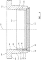
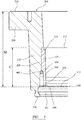
Wear collar 120 comprises a generally annular sleeve-like body having a radially inward facingsurface 202 and a radially outward facingsurface 205 extending axially between a firstupper end 213 and a secondlower end 212. A radial wall thickness ofcollar 120 is less than the corresponding wall thickness ofbushing 112 between the opposed and respective inward and outward facingsurfaces collar 120 is approximately equal to or less than half the corresponding wall thickness ofwall bushing 112.First end 213 ofcollar 120 is configured to abutannular shoulder 210 to prevent upward axial movement ofcollar 120 beyond theannular recess 214 that is indented at the inner region ofcollar 120 and defined by the radially inward facingsurface 201 andshoulder 210. Due to the relative radial length ofshoulder 210 and the radial wall thickness ofcollar 120,collar 120 projects radially inward from inward facingsurfaces bushing 112 so as to stand internally 'proud' ofbushing 112 when mounted in position as shown infigures 2 to 6 . - The radially inward facing
surface 202 ofcollar 120 comprises achamfer 500 atsecond end 212 as illustrated infigure 5 and6 . That is, inward facingsurface 202 tapers outwardly atchamfer 500 towards the outward facingsurface 205. This configuration provides a smooth transition with an annularcurved region 501 ofbushing 112 that extends radially inward fromfoot 206 at bushingsecond end 207.Region 501 provides an annular cavity to accommodate a part of sealingring 121 and a volume of lubricant oil.Sealing ring 121 is further held in position and trapped axially againstfoot 206 by anannular rim 217 that projects radially inward at an axially lower region ofcentral boss 117. -
Collar 120 is rotatably and axially locked atbushing 112 by a plurality of attachment elements formed as threaded bolts (or screws) 400. Eachbolt 400 is received respectively within a threaded bore that extends axially upward from a region of bushingsecond end 207 and thesecond end 212 ofcollar 120. In particular, each bore is formed by cooperatively mated part cylindrical recesses 401, 402 embedded within the respective axially lower ends ofcollar 120 andbushing 112. Accordingly, eachbolt 400 is positioned at the junction between the collar outward facingsurface 205 and the bushing inward facingsurface 201 at the respective lower second ends 212, 207. In this configuration,collar 120 may be conveniently attached and demounted atbushing 112 via theaxially extending bolts 400 being accessible from the axially lower region ofcentral boss 117 whenshaft 107 andsleeve 114 are removed. Accordingly, eachbolt 400 comprises adrive head 600 engageable by a suitable tool. - According to further specific implementations,
collar 120 may be attached and rotatably locked atbushing 112 via any convenient means of attachment. Such attachment arrangements may comprise tong and groove configurations in whichcollar 120 slides axially upward withinbushing 112 and is then rotated to locate anchorage lugs extending radially fromcollar 120 into anchorage recesses indented on the inward facing surface ofbushing 112. - According to yet further specific implementations,
collar 120 andbushing 112 may comprise cooperating screw threads formed atrespective surfaces collar 120 atbushing 112 with such locking elements provided at the second axiallylower regions respective bushing 112 andcollar 120. - To reduce wear and extend the longevity of
collar 120,collar 120 comprises a material different to a material ofbushing 112. In particular,collar 120 comprises a metal, ceramic or polymer material having enhanced wear resistance relative to the material ofbushing 112 which is typically grey iron. In one specific implementation,collar 120 comprises a bronze alloy. This is particularly advantageous to allow shrink-fitting ofcollar 120 at bushing 112 (to provide a secure friction-fit arrangement) optionally followed by subsequent mounting ofbolts 400 withinrespective bores - When assembled as illustrated in
figures 1 to 6 , radially inward facingsurface 202 ofcollar 120 is positioned for mating contact against a radially outward facing surface ofmain shaft sleeve 114. Theupper end region 113 ofshaft 107 is capable of gyroscopic precession within the annular bore of the bushing assembly that is defined by the inward facingsurface 203 ofbushing 112 andsurface 202 ofcollar 120. Following extended use,collar 120 may be readily demounted and replaced atbushing 112 without any wear or damage tobushing 112 due to the rotation ofsleeve 114 andshaft region 113 withinboss 117. The present bushing assembly is therefore advantageous to reduce the amount of material that is required to be replaced and to optimise the physical and mechanical characteristics of the selected components of the assembly suitable for wear resistance as effective wear parts. - Referring to
figure 5 , an axial length M ofbushing 112 is defined as the axial distance between the bushing first end 208 (corresponding to uppermost annular surface 219) and the bushingsecond end 207 and in particular aregion 502 ofbushing 112 that is aligned at the same axial position as the lowermostsecond end 212 ofcollar 120.Region 502 is accordingly positioned axially between the bushing first 208 and second 207 ends and axially above thefoot 206. Additionally, a relative axial length C ofcollar 120 is defined as the axial distance between the respective collar first 213 and second 212 ends and corresponds to a total axial length ofcollar 120. - According to the specific implementation, axial length M is greater than axial length C and in particular, length C is less than 75% (and optionally less than 60%) of length M. Accordingly,
collar 120 does not extend into the axially upper region ofbushing 112. Such an arrangement is advantageous to optimise the volume of the higher performance material ofcollar 120 within the present bushing assembly.
Claims (13)
- A gyratory crusher spider bushing assembly for positioning radially intermediate a topshell spider (110) and a crusher main shaft (107) configured for gyroscopic precession within a crusher, the assembly comprising:an annular main body (112) extending around an axis (122) of the assembly and having a radially outward facing surface (215) for positioning opposed to the topshell spider (110) and a radially inward facing surface (201, 203) for positioning opposed to the main shaft (107) or a sleeve (114) surrounding the main shaft (107), the main body (112) formed from a first material;the main body (112) comprising a first end (208) having a mount flange (209) extending radially outward and a second end (207) intended to be positioned lowermost within the crusher relative to the first end (208);an annular wear collar (120) positioned at the inward facing surface (201) and extending radially inward from the main body (112) to contact the main shaft (107) or the sleeve (114);the collar (120) mounted at the main body (112) to prevent independent rotation of the collar (120) about the axis (122) relative to the main body (112);the collar (120) comprises a second material having a wear resistance greater than the first material; andan axial length (C) corresponding to a distance between a first end (213) and a second end (212) of the collar (120) that is less than that 75% of an axial length (M) the main body (112) corresponding to a distance between the first end (208) of the main body (112) and a region (502) of the main body (112) aligned at the same axial position as the second end (212) of the collar (120);the collar (120) positioned axially closest to the second end (207) of the main body (112) relative to the first end (208) of the main body (112);the inward facing surface (201, 203) and/or the collar (120) comprises a radially extending abutment (210) to axially separate and prevent the collar (120) from moving axially towards the first end (208);characterised in that:the inward facing surface (201, 203) of the main body (112) is aligned transverse to the axis (122) of the assembly to tilt radially outward such that a radial separation distance of said inward facing surface (201, 203) at an axial position of the first end (208) of the main body (112) is more than a radial separation distance of said inward facing surface (201, 203) at an axial position at or towards the abutment (210).
- The assembly as claimed in claim 1 wherein the axial length (C) of the collar (120) is less than 60% of the axial length (M) of the main body (112).
- The assembly as claimed in claim 1 wherein the abutment (210) comprises a step configuration at the inward facing surface (201, 203) of the main body (112).
- The assembly as claimed in claim 3 wherein the step configuration comprises a recess (214) at the inward facing surface (201, 203) extending axially from the second end (207), the recess (214) terminated at an axially upper region by an annular shoulder (210) such that the collar (120) is at least partially accommodated within the recess (214) and the first end (213) of the collar (120) abuts the annular shoulder (210).
- The assembly as claimed in claim 4 further comprising a plurality of attachment elements (400) extending between the collar (120) and the main body (112).
- The assembly as claimed in claim 5 wherein the attachment elements (400) are aligned coaxially with the main body (112) and/or the collar (120) and are positioned axially at or towards the second end (207) of the main body (112).
- The assembly as claimed in claim 6 wherein the collar (120) is positioned exclusively axially within a region of the main body (112) closest to the second end (207) relative to the first end (208) such that a region of the main body (112) closest to the first end (208) is devoid of the collar (120).
- The assembly as claimed in any preceding claim wherein the axial length (C) of the collar (120) is in the range 20 to 60% of the axial length (M) of the main body (112).
- The assembly as claimed in any preceding claim wherein the physical or mechanical properties of second material relative to the first material comprise anyone of a combination of:a material that has a higher hardness;a softer material having reduced friction or friction coefficient;a material that has a lower surface pressure.
- The assembly as claimed in any preceding claim wherein the second material comprises any one or a combination of the set of:• a metal or metal alloy;• a copper/zinc based alloy;• a manganese steel;• a polymer;• a ceramic.
- The assembly as claimed in any preceding claim wherein a radial thickness of the main body (112) between the inward (201) and outward (215) facing surfaces is greater than a radial thickness of the collar (120) between a radially inward (202) and a radially outward (205) facing surface of the collar (120).
- The assembly as claimed in any preceding claim wherein the second end (212) of the collar (120) comprising a chamfer (500) to decrease a radial thickness of the collar (120) at the second end (207) between an inward (202) and an outward (205) facing surface of the collar (120).
- A gyratory crusher comprising an assembly as claimed in any preceding claim.
Priority Applications (8)
| Application Number | Priority Date | Filing Date | Title |
|---|---|---|---|
| EP13193474.7A EP2873461B1 (en) | 2013-11-19 | 2013-11-19 | A gyratory crusher spider bushing assembly |
| PCT/EP2014/073187 WO2015074843A1 (en) | 2013-11-19 | 2014-10-29 | A gyratory crusher spider bushing assembly |
| CA2928327A CA2928327A1 (en) | 2013-11-19 | 2014-10-29 | A gyratory crusher spider bushing assembly |
| RU2016124101A RU2667763C1 (en) | 2013-11-19 | 2014-10-29 | Gyratory crusher spider bushing assembly |
| AU2014352185A AU2014352185B2 (en) | 2013-11-19 | 2014-10-29 | A gyratory crusher spider bushing assembly |
| US15/037,677 US10328433B2 (en) | 2013-11-19 | 2014-10-29 | Gyratory crusher spider bushing assembly |
| CN201480062881.8A CN105980060B (en) | 2013-11-19 | 2014-10-29 | Gyratory crusher bracket bush assembly |
| CL2016001121A CL2016001121A1 (en) | 2013-11-19 | 2016-05-11 | Spider bearing assembly for rotary crusher |
Applications Claiming Priority (1)
| Application Number | Priority Date | Filing Date | Title |
|---|---|---|---|
| EP13193474.7A EP2873461B1 (en) | 2013-11-19 | 2013-11-19 | A gyratory crusher spider bushing assembly |
Publications (2)
| Publication Number | Publication Date |
|---|---|
| EP2873461A1 EP2873461A1 (en) | 2015-05-20 |
| EP2873461B1 true EP2873461B1 (en) | 2017-04-12 |
Family
ID=49622692
Family Applications (1)
| Application Number | Title | Priority Date | Filing Date |
|---|---|---|---|
| EP13193474.7A Active EP2873461B1 (en) | 2013-11-19 | 2013-11-19 | A gyratory crusher spider bushing assembly |
Country Status (8)
| Country | Link |
|---|---|
| US (1) | US10328433B2 (en) |
| EP (1) | EP2873461B1 (en) |
| CN (1) | CN105980060B (en) |
| AU (1) | AU2014352185B2 (en) |
| CA (1) | CA2928327A1 (en) |
| CL (1) | CL2016001121A1 (en) |
| RU (1) | RU2667763C1 (en) |
| WO (1) | WO2015074843A1 (en) |
Families Citing this family (7)
| Publication number | Priority date | Publication date | Assignee | Title |
|---|---|---|---|---|
| DE102014105415A1 (en) * | 2014-04-16 | 2015-10-22 | Thyssenkrupp Ag | Rolling bush in a crusher |
| US20170304830A1 (en) | 2016-04-25 | 2017-10-26 | Metso Minerals Industries, Inc. | Spider bushing assembly for a gyratory crusher |
| FR3064035B1 (en) * | 2017-03-16 | 2019-04-19 | Sogefi Air & Cooling | REMOVABLE SLEEVE FOR HOLDING AND ATTACHING SCREWS |
| CN107790247A (en) * | 2017-11-16 | 2018-03-13 | 广州安适易环境科技有限公司 | Verticle refuse crusher |
| US20210402410A1 (en) * | 2018-10-01 | 2021-12-30 | Sandvik Srp Ab | Gyratory crusher main shaft sleeve |
| EP4221896A1 (en) * | 2020-10-01 | 2023-08-09 | Sandvik SRP AB | Gyratory crusher spider bushing |
| CN112377914A (en) * | 2020-10-09 | 2021-02-19 | 江苏朗誉环保设备有限公司 | Hazardous waste slag plasma incinerator and incineration method thereof |
Family Cites Families (23)
| Publication number | Priority date | Publication date | Assignee | Title |
|---|---|---|---|---|
| BE370558A (en) * | ||||
| BE465824A (en) * | ||||
| US1110887A (en) | 1909-05-03 | 1914-09-15 | Allis Chalmers Mfg Co | Gyratory crusher. |
| US1528741A (en) * | 1921-03-29 | 1925-03-03 | Weston And Brooker | Gyratory crushing machine |
| US1748102A (en) | 1929-05-24 | 1930-02-25 | Traylor Engineering & Mfg Comp | Crusher |
| US2598548A (en) | 1948-07-09 | 1952-05-27 | Hobart Fed Engineering Corp | Meat processing machine |
| US2977057A (en) * | 1958-05-16 | 1961-03-28 | Fuller Co | Gyratory crusher |
| SU142514A1 (en) | 1961-04-11 | 1961-11-30 | С.А. Крисанов | Lip seal spherical bushing cone crushers |
| US3456889A (en) * | 1967-04-10 | 1969-07-22 | Allis Chalmers Mfg Co | Spider bearing assembly for gyratory crushers |
| US3813047A (en) * | 1972-12-07 | 1974-05-28 | Allis Chalmers | Spider bearing assembly for gyratory crushers |
| US4060205A (en) | 1976-11-08 | 1977-11-29 | Allis-Chalmers Corporation | Hydraulic accumulator for use with gyratory crushers and combination of such accumulator with a gyratory crusher |
| TW265277B (en) * | 1993-02-15 | 1995-12-11 | Clyde Ind Ltd Trading As Jaques | |
| AUPM739094A0 (en) * | 1994-08-12 | 1994-09-01 | Ledger Engineering Pty Ltd | A support assembly for a gyratory crusher |
| RU14532U1 (en) | 2000-02-17 | 2000-08-10 | Общество с ограниченной ответственностью Научно-производственное общество "Металлоресурс" | CONE CRUSHER |
| US6536694B2 (en) * | 2001-01-05 | 2003-03-25 | Sandvik Ab | Gyratory crusher spider guards |
| US6550707B2 (en) * | 2001-01-05 | 2003-04-22 | Sandvik Ab | Gyratory crusher dust seal system |
| CN2608118Y (en) * | 2003-03-21 | 2004-03-31 | 陈正辉 | Vertical rolling and crushing machine |
| JP3743719B2 (en) * | 2003-06-26 | 2006-02-08 | 株式会社アーステクニカ | Rotating crusher |
| CN101816965B (en) * | 2009-12-03 | 2014-08-13 | 浙江双金机械集团股份有限公司 | Sand making cavity special for cone sand making machine |
| US8070084B2 (en) * | 2010-02-05 | 2011-12-06 | Metso Minerals Industries, Inc. | Spider having spider arms with open channel |
| SE534784C2 (en) | 2010-05-03 | 2011-12-20 | Sandvik Intellectual Property | Dust seal for gyratory crusher |
| CN202983765U (en) * | 2012-01-18 | 2013-06-12 | 江门市阪桥电子材料有限公司 | Device for automatically adding printing ink |
| EP2859951B1 (en) * | 2013-10-11 | 2016-02-24 | Sandvik Intellectual Property AB | Gyratory crusher spider arm shields |
-
2013
- 2013-11-19 EP EP13193474.7A patent/EP2873461B1/en active Active
-
2014
- 2014-10-29 CN CN201480062881.8A patent/CN105980060B/en not_active Expired - Fee Related
- 2014-10-29 WO PCT/EP2014/073187 patent/WO2015074843A1/en active Application Filing
- 2014-10-29 RU RU2016124101A patent/RU2667763C1/en active
- 2014-10-29 AU AU2014352185A patent/AU2014352185B2/en not_active Ceased
- 2014-10-29 CA CA2928327A patent/CA2928327A1/en not_active Abandoned
- 2014-10-29 US US15/037,677 patent/US10328433B2/en not_active Expired - Fee Related
-
2016
- 2016-05-11 CL CL2016001121A patent/CL2016001121A1/en unknown
Non-Patent Citations (1)
| Title |
|---|
| None * |
Also Published As
| Publication number | Publication date |
|---|---|
| AU2014352185B2 (en) | 2018-07-12 |
| US20160288129A1 (en) | 2016-10-06 |
| EP2873461A1 (en) | 2015-05-20 |
| RU2667763C1 (en) | 2018-09-24 |
| WO2015074843A1 (en) | 2015-05-28 |
| CA2928327A1 (en) | 2015-05-28 |
| AU2014352185A1 (en) | 2016-05-19 |
| CN105980060A (en) | 2016-09-28 |
| CN105980060B (en) | 2019-02-15 |
| US10328433B2 (en) | 2019-06-25 |
| RU2016124101A (en) | 2017-12-25 |
| CL2016001121A1 (en) | 2017-01-20 |
Similar Documents
| Publication | Publication Date | Title |
|---|---|---|
| EP2873461B1 (en) | A gyratory crusher spider bushing assembly | |
| US9827568B2 (en) | Gyratory crusher main shaft sleeve | |
| AU2014286527B2 (en) | Gyratory crusher topshell assembly | |
| US9205427B2 (en) | Gyratory crusher outer crushing shell | |
| EP2716365B1 (en) | Gyratory crusher bearing | |
| EP2692442A1 (en) | Gyratory crusher outer crushing shell | |
| EP2641657B1 (en) | Gyratory crusher bearing | |
| US10173221B2 (en) | Gyratory crusher crushing head | |
| CA2937698C (en) | System and method for hydraulically removing a socket from a mainshaft of a gyrational crusher | |
| US6520438B2 (en) | Gyratory crusher mainshaft | |
| JP2016120447A (en) | Dust seal structure of gyratory crusher |
Legal Events
| Date | Code | Title | Description |
|---|---|---|---|
| PUAI | Public reference made under article 153(3) epc to a published international application that has entered the european phase |
Free format text: ORIGINAL CODE: 0009012 |
|
| 17P | Request for examination filed |
Effective date: 20131119 |
|
| AK | Designated contracting states |
Kind code of ref document: A1 Designated state(s): AL AT BE BG CH CY CZ DE DK EE ES FI FR GB GR HR HU IE IS IT LI LT LU LV MC MK MT NL NO PL PT RO RS SE SI SK SM TR |
|
| AX | Request for extension of the european patent |
Extension state: BA ME |
|
| RBV | Designated contracting states (corrected) |
Designated state(s): AL AT BE BG CH CY CZ DE DK EE ES FI FR GB GR HR HU IE IS IT LI LT LU LV MC MK MT NL NO PL PT RO RS SE SI SK SM TR |
|
| GRAP | Despatch of communication of intention to grant a patent |
Free format text: ORIGINAL CODE: EPIDOSNIGR1 |
|
| INTG | Intention to grant announced |
Effective date: 20160527 |
|
| GRAJ | Information related to disapproval of communication of intention to grant by the applicant or resumption of examination proceedings by the epo deleted |
Free format text: ORIGINAL CODE: EPIDOSDIGR1 |
|
| INTC | Intention to grant announced (deleted) | ||
| GRAP | Despatch of communication of intention to grant a patent |
Free format text: ORIGINAL CODE: EPIDOSNIGR1 |
|
| GRAS | Grant fee paid |
Free format text: ORIGINAL CODE: EPIDOSNIGR3 |
|
| GRAA | (expected) grant |
Free format text: ORIGINAL CODE: 0009210 |
|
| INTG | Intention to grant announced |
Effective date: 20170224 |
|
| AK | Designated contracting states |
Kind code of ref document: B1 Designated state(s): AL AT BE BG CH CY CZ DE DK EE ES FI FR GB GR HR HU IE IS IT LI LT LU LV MC MK MT NL NO PL PT RO RS SE SI SK SM TR |
|
| REG | Reference to a national code |
Ref country code: GB Ref legal event code: FG4D |
|
| REG | Reference to a national code |
Ref country code: CH Ref legal event code: EP |
|
| REG | Reference to a national code |
Ref country code: IE Ref legal event code: FG4D |
|
| REG | Reference to a national code |
Ref country code: AT Ref legal event code: REF Ref document number: 883315 Country of ref document: AT Kind code of ref document: T Effective date: 20170515 |
|
| REG | Reference to a national code |
Ref country code: DE Ref legal event code: R096 Ref document number: 602013019688 Country of ref document: DE |
|
| REG | Reference to a national code |
Ref country code: SE Ref legal event code: TRGR |
|
| REG | Reference to a national code |
Ref country code: NL Ref legal event code: MP Effective date: 20170412 |
|
| REG | Reference to a national code |
Ref country code: LT Ref legal event code: MG4D |
|
| REG | Reference to a national code |
Ref country code: NO Ref legal event code: T2 Effective date: 20170412 |
|
| REG | Reference to a national code |
Ref country code: AT Ref legal event code: MK05 Ref document number: 883315 Country of ref document: AT Kind code of ref document: T Effective date: 20170412 |
|
| PG25 | Lapsed in a contracting state [announced via postgrant information from national office to epo] |
Ref country code: NL Free format text: LAPSE BECAUSE OF FAILURE TO SUBMIT A TRANSLATION OF THE DESCRIPTION OR TO PAY THE FEE WITHIN THE PRESCRIBED TIME-LIMIT Effective date: 20170412 |
|
| REG | Reference to a national code |
Ref country code: FR Ref legal event code: PLFP Year of fee payment: 5 |
|
| PG25 | Lapsed in a contracting state [announced via postgrant information from national office to epo] |
Ref country code: GR Free format text: LAPSE BECAUSE OF FAILURE TO SUBMIT A TRANSLATION OF THE DESCRIPTION OR TO PAY THE FEE WITHIN THE PRESCRIBED TIME-LIMIT Effective date: 20170713 Ref country code: LT Free format text: LAPSE BECAUSE OF FAILURE TO SUBMIT A TRANSLATION OF THE DESCRIPTION OR TO PAY THE FEE WITHIN THE PRESCRIBED TIME-LIMIT Effective date: 20170412 Ref country code: AT Free format text: LAPSE BECAUSE OF FAILURE TO SUBMIT A TRANSLATION OF THE DESCRIPTION OR TO PAY THE FEE WITHIN THE PRESCRIBED TIME-LIMIT Effective date: 20170412 Ref country code: ES Free format text: LAPSE BECAUSE OF FAILURE TO SUBMIT A TRANSLATION OF THE DESCRIPTION OR TO PAY THE FEE WITHIN THE PRESCRIBED TIME-LIMIT Effective date: 20170412 Ref country code: HR Free format text: LAPSE BECAUSE OF FAILURE TO SUBMIT A TRANSLATION OF THE DESCRIPTION OR TO PAY THE FEE WITHIN THE PRESCRIBED TIME-LIMIT Effective date: 20170412 |
|
| PG25 | Lapsed in a contracting state [announced via postgrant information from national office to epo] |
Ref country code: LV Free format text: LAPSE BECAUSE OF FAILURE TO SUBMIT A TRANSLATION OF THE DESCRIPTION OR TO PAY THE FEE WITHIN THE PRESCRIBED TIME-LIMIT Effective date: 20170412 Ref country code: RS Free format text: LAPSE BECAUSE OF FAILURE TO SUBMIT A TRANSLATION OF THE DESCRIPTION OR TO PAY THE FEE WITHIN THE PRESCRIBED TIME-LIMIT Effective date: 20170412 Ref country code: IS Free format text: LAPSE BECAUSE OF FAILURE TO SUBMIT A TRANSLATION OF THE DESCRIPTION OR TO PAY THE FEE WITHIN THE PRESCRIBED TIME-LIMIT Effective date: 20170812 Ref country code: PL Free format text: LAPSE BECAUSE OF FAILURE TO SUBMIT A TRANSLATION OF THE DESCRIPTION OR TO PAY THE FEE WITHIN THE PRESCRIBED TIME-LIMIT Effective date: 20170412 Ref country code: BG Free format text: LAPSE BECAUSE OF FAILURE TO SUBMIT A TRANSLATION OF THE DESCRIPTION OR TO PAY THE FEE WITHIN THE PRESCRIBED TIME-LIMIT Effective date: 20170712 |
|
| REG | Reference to a national code |
Ref country code: DE Ref legal event code: R097 Ref document number: 602013019688 Country of ref document: DE |
|
| PG25 | Lapsed in a contracting state [announced via postgrant information from national office to epo] |
Ref country code: DK Free format text: LAPSE BECAUSE OF FAILURE TO SUBMIT A TRANSLATION OF THE DESCRIPTION OR TO PAY THE FEE WITHIN THE PRESCRIBED TIME-LIMIT Effective date: 20170412 Ref country code: RO Free format text: LAPSE BECAUSE OF FAILURE TO SUBMIT A TRANSLATION OF THE DESCRIPTION OR TO PAY THE FEE WITHIN THE PRESCRIBED TIME-LIMIT Effective date: 20170412 Ref country code: EE Free format text: LAPSE BECAUSE OF FAILURE TO SUBMIT A TRANSLATION OF THE DESCRIPTION OR TO PAY THE FEE WITHIN THE PRESCRIBED TIME-LIMIT Effective date: 20170412 Ref country code: CZ Free format text: LAPSE BECAUSE OF FAILURE TO SUBMIT A TRANSLATION OF THE DESCRIPTION OR TO PAY THE FEE WITHIN THE PRESCRIBED TIME-LIMIT Effective date: 20170412 Ref country code: SK Free format text: LAPSE BECAUSE OF FAILURE TO SUBMIT A TRANSLATION OF THE DESCRIPTION OR TO PAY THE FEE WITHIN THE PRESCRIBED TIME-LIMIT Effective date: 20170412 |
|
| PLBE | No opposition filed within time limit |
Free format text: ORIGINAL CODE: 0009261 |
|
| STAA | Information on the status of an ep patent application or granted ep patent |
Free format text: STATUS: NO OPPOSITION FILED WITHIN TIME LIMIT |
|
| PG25 | Lapsed in a contracting state [announced via postgrant information from national office to epo] |
Ref country code: SM Free format text: LAPSE BECAUSE OF FAILURE TO SUBMIT A TRANSLATION OF THE DESCRIPTION OR TO PAY THE FEE WITHIN THE PRESCRIBED TIME-LIMIT Effective date: 20170412 Ref country code: IT Free format text: LAPSE BECAUSE OF FAILURE TO SUBMIT A TRANSLATION OF THE DESCRIPTION OR TO PAY THE FEE WITHIN THE PRESCRIBED TIME-LIMIT Effective date: 20170412 |
|
| 26N | No opposition filed |
Effective date: 20180115 |
|
| PG25 | Lapsed in a contracting state [announced via postgrant information from national office to epo] |
Ref country code: SI Free format text: LAPSE BECAUSE OF FAILURE TO SUBMIT A TRANSLATION OF THE DESCRIPTION OR TO PAY THE FEE WITHIN THE PRESCRIBED TIME-LIMIT Effective date: 20170412 |
|
| PG25 | Lapsed in a contracting state [announced via postgrant information from national office to epo] |
Ref country code: MC Free format text: LAPSE BECAUSE OF FAILURE TO SUBMIT A TRANSLATION OF THE DESCRIPTION OR TO PAY THE FEE WITHIN THE PRESCRIBED TIME-LIMIT Effective date: 20170412 |
|
| PG25 | Lapsed in a contracting state [announced via postgrant information from national office to epo] |
Ref country code: CH Free format text: LAPSE BECAUSE OF NON-PAYMENT OF DUE FEES Effective date: 20171130 Ref country code: LI Free format text: LAPSE BECAUSE OF NON-PAYMENT OF DUE FEES Effective date: 20171130 |
|
| PG25 | Lapsed in a contracting state [announced via postgrant information from national office to epo] |
Ref country code: LU Free format text: LAPSE BECAUSE OF NON-PAYMENT OF DUE FEES Effective date: 20171119 |
|
| REG | Reference to a national code |
Ref country code: BE Ref legal event code: MM Effective date: 20171130 |
|
| REG | Reference to a national code |
Ref country code: IE Ref legal event code: MM4A |
|
| PG25 | Lapsed in a contracting state [announced via postgrant information from national office to epo] |
Ref country code: MT Free format text: LAPSE BECAUSE OF NON-PAYMENT OF DUE FEES Effective date: 20171119 |
|
| REG | Reference to a national code |
Ref country code: FR Ref legal event code: PLFP Year of fee payment: 6 |
|
| PG25 | Lapsed in a contracting state [announced via postgrant information from national office to epo] |
Ref country code: IE Free format text: LAPSE BECAUSE OF NON-PAYMENT OF DUE FEES Effective date: 20171119 |
|
| PG25 | Lapsed in a contracting state [announced via postgrant information from national office to epo] |
Ref country code: BE Free format text: LAPSE BECAUSE OF NON-PAYMENT OF DUE FEES Effective date: 20171130 |
|
| PG25 | Lapsed in a contracting state [announced via postgrant information from national office to epo] |
Ref country code: HU Free format text: LAPSE BECAUSE OF FAILURE TO SUBMIT A TRANSLATION OF THE DESCRIPTION OR TO PAY THE FEE WITHIN THE PRESCRIBED TIME-LIMIT; INVALID AB INITIO Effective date: 20131119 |
|
| PG25 | Lapsed in a contracting state [announced via postgrant information from national office to epo] |
Ref country code: CY Free format text: LAPSE BECAUSE OF FAILURE TO SUBMIT A TRANSLATION OF THE DESCRIPTION OR TO PAY THE FEE WITHIN THE PRESCRIBED TIME-LIMIT Effective date: 20170412 |
|
| PG25 | Lapsed in a contracting state [announced via postgrant information from national office to epo] |
Ref country code: MK Free format text: LAPSE BECAUSE OF FAILURE TO SUBMIT A TRANSLATION OF THE DESCRIPTION OR TO PAY THE FEE WITHIN THE PRESCRIBED TIME-LIMIT Effective date: 20170412 |
|
| PG25 | Lapsed in a contracting state [announced via postgrant information from national office to epo] |
Ref country code: PT Free format text: LAPSE BECAUSE OF FAILURE TO SUBMIT A TRANSLATION OF THE DESCRIPTION OR TO PAY THE FEE WITHIN THE PRESCRIBED TIME-LIMIT Effective date: 20170412 |
|
| PG25 | Lapsed in a contracting state [announced via postgrant information from national office to epo] |
Ref country code: AL Free format text: LAPSE BECAUSE OF FAILURE TO SUBMIT A TRANSLATION OF THE DESCRIPTION OR TO PAY THE FEE WITHIN THE PRESCRIBED TIME-LIMIT Effective date: 20170412 |
|
| PGFP | Annual fee paid to national office [announced via postgrant information from national office to epo] |
Ref country code: TR Payment date: 20201118 Year of fee payment: 8 |
|
| PGFP | Annual fee paid to national office [announced via postgrant information from national office to epo] |
Ref country code: NO Payment date: 20201110 Year of fee payment: 8 Ref country code: FR Payment date: 20201026 Year of fee payment: 8 Ref country code: GB Payment date: 20201111 Year of fee payment: 8 Ref country code: SE Payment date: 20201110 Year of fee payment: 8 Ref country code: DE Payment date: 20201103 Year of fee payment: 8 Ref country code: FI Payment date: 20201109 Year of fee payment: 8 |
|
| REG | Reference to a national code |
Ref country code: DE Ref legal event code: R119 Ref document number: 602013019688 Country of ref document: DE |
|
| REG | Reference to a national code |
Ref country code: NO Ref legal event code: MMEP |
|
| REG | Reference to a national code |
Ref country code: FI Ref legal event code: MAE |
|
| GBPC | Gb: european patent ceased through non-payment of renewal fee |
Effective date: 20211119 |
|
| PG25 | Lapsed in a contracting state [announced via postgrant information from national office to epo] |
Ref country code: SE Free format text: LAPSE BECAUSE OF NON-PAYMENT OF DUE FEES Effective date: 20211120 Ref country code: NO Free format text: LAPSE BECAUSE OF NON-PAYMENT OF DUE FEES Effective date: 20211130 |
|
| PG25 | Lapsed in a contracting state [announced via postgrant information from national office to epo] |
Ref country code: FI Free format text: LAPSE BECAUSE OF NON-PAYMENT OF DUE FEES Effective date: 20211119 |
|
| PG25 | Lapsed in a contracting state [announced via postgrant information from national office to epo] |
Ref country code: GB Free format text: LAPSE BECAUSE OF NON-PAYMENT OF DUE FEES Effective date: 20211119 Ref country code: DE Free format text: LAPSE BECAUSE OF NON-PAYMENT OF DUE FEES Effective date: 20220601 |
|
| PG25 | Lapsed in a contracting state [announced via postgrant information from national office to epo] |
Ref country code: FR Free format text: LAPSE BECAUSE OF NON-PAYMENT OF DUE FEES Effective date: 20211130 |