EP0050090A2 - Conical crusher - Google Patents
Conical crusher Download PDFInfo
- Publication number
- EP0050090A2 EP0050090A2 EP81630063A EP81630063A EP0050090A2 EP 0050090 A2 EP0050090 A2 EP 0050090A2 EP 81630063 A EP81630063 A EP 81630063A EP 81630063 A EP81630063 A EP 81630063A EP 0050090 A2 EP0050090 A2 EP 0050090A2
- Authority
- EP
- European Patent Office
- Prior art keywords
- crusher
- bowl
- assembly
- frame
- eccentric
- Prior art date
- Legal status (The legal status is an assumption and is not a legal conclusion. Google has not performed a legal analysis and makes no representation as to the accuracy of the status listed.)
- Granted
Links
Images



Classifications
-
- B—PERFORMING OPERATIONS; TRANSPORTING
- B02—CRUSHING, PULVERISING, OR DISINTEGRATING; PREPARATORY TREATMENT OF GRAIN FOR MILLING
- B02C—CRUSHING, PULVERISING, OR DISINTEGRATING IN GENERAL; MILLING GRAIN
- B02C2/00—Crushing or disintegrating by gyratory or cone crushers
- B02C2/02—Crushing or disintegrating by gyratory or cone crushers eccentrically moved
- B02C2/04—Crushing or disintegrating by gyratory or cone crushers eccentrically moved with vertical axis
- B02C2/045—Crushing or disintegrating by gyratory or cone crushers eccentrically moved with vertical axis and with bowl adjusting or controlling mechanisms
Definitions
- the inner annular surface of adjusting ring 56 is helically threaded to receive a complementary threaded outer annular surface of the crusher bowl 96. Rotation of bowl 96 thus adjusts the relative position thereof with respect to ring 56 and changes the setting of the crushing members-
- the upper extension of bowl 96 terminates in a horizontal flange 98 to which is bolted a downward extending annular adjustment cap ring 100.
- an annular dust shell 102 is bolted to ring 56 so that shell 102 is closely circumscribed by ring 100 in a telescoping relationship.
- Seal 104 is provided to completely enclose the volume.
- a second seal member 106 is secured to the under surface of adjusting ring 56 and contacts the lower extension of bowl 96 thus preventing upward entry of material into the area between the threads.
- safety relief valves 260, 262, 264 are provided for each circuit.
- a single rotary actuator motor 266 may be provided as shown with a divided outlet 268, a majority of which is directed toward the tramp release cylinders and ram assemblies.
Landscapes
- Engineering & Computer Science (AREA)
- Mechanical Engineering (AREA)
- Food Science & Technology (AREA)
- Crushing And Grinding (AREA)
- Disintegrating Or Milling (AREA)
Abstract
Description
- Generally, conical crushers have head assemblies which are caused to gyrate by an eccentric mechanism driven by various power sources. The head assemblies are covered by a wearing mantle which actually engages the material being crushed. Spaced from the head assembly and supported by the crusher frame is a bowl fitted with a liner which provides the opposing surface to the mantle for crushing the material.
- The head which gyrates under the influence of the eccentric and moves relative to the frame must have a bearing surface which is positioned on some stationary bearing surface. Various types of bearing supports have been employed in the conical crushers of the prior art. A problem which often results, however, is the undesired misalignment which can and does occur during extended operation of the crusher which can adversely affect further satisfactory operation of the crusher. It is thus a paramount object of the present invention to provide a crusher with a bearing support mechanism which minimizes misalignment over the life of the crusher.
- Other objects and advantages will be evident from a reading of the detailed description including the beneficial use of a tramp release means for its customary function and additionally as a jacking device to clear the throat of the crusher when packed with material.
- The conical cone crusher apparatus of the present invention is generally comprised of an annular shell and central hub to which an annular ring is mounted for vertical movement. The bowl and liner are mounted to the annular ring. A head assembly including its liner is mounted for movement via a bearing mechanism directly to a stationary shaft within the hub. Gyration of the head relative to the bowl assembly is provided by an eccentric mounted for movement about the stationary shaft.
- A plurality of tramp release means bias the bowl and liner against a seat in position near the mantle and head assembly. The tramp release means is responsive to increased counter-forces which, when greater than its biasing force, causes the bowl to move upward relative to the head assembly, increasing the space therebetween and allowing the harder tramp material to pass through. The release means also provides a jacking mechanism which can be employed should, for example, the crusher throat be jammed with material and in need of being cleared. These functions along with a mechanical seat provides for positive positioning of the bowl after an operative sequence of the tramp release means.
- An embodiment of the conical crusher will now be described with reference to the drawings, wherein:
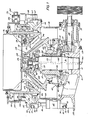
- Figure 1 is a side view, rartly in section, of a crusher assembly of the present invention.
- Figure 2 is a plan view in section of the lower half of the crusher in Figure 1 depicting the hub and extending arms.
- Figure 3 is a side section view taken along lines 3-3 of Figure 2.
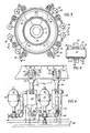
- Figure 4 is a perspective side view of a portion of a crusher of the present invention taken along lines 4-4 of Figur 5, showinlthe tramp release cylinders, accumulator tanks, and assorted piping.
- Figure 5 is a plan view of a crusher of the present invention (with much detail omitted) depicting the tramp release cylinders.
- Figure 6 is a sectional view taken along lines 6-6 of Figure 4 showing the spherical bushing to which the clevis is attached.
- Figure 7 is a simplified plan view of a crusher of the present invention illustrating the ram assembly for rotating the bowl.
- Figure 8 is a view, partly in section, taken along lines 8-8 of Figure 7.
- Figure 9 is a view of the ram assembly when moving the adjustment cap ring counter-clockwise.
- Figure 10 is a view of the ram assembly when moving the adjustment cap ring clockwise.
- Figure lla is a schematic of a prior art arrangment for bearing placement for the head assembly.
- Figure llb is a schematic of a prior art arrangement where the lower bearing surface is mounted on a moveable piston.
- Figure llc is a schematic of the bearing arrangement as set forth in the present invention.
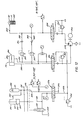
- Figure 12 is a hydraulic schematic of the system employed in a crusher of the present invention. Crusher structure:
- Referring to Figure 1, a
central hub 10 is formed from a cast stell member having a thickannular wall 12 forming an upwardly divergingvertical bore 14 adapted to receive acylindrical support shaft 16. Extending outwardly fromcentral hub 10 is ahousing 18 which encloses drive pinion 26. Supported byhouse 18 and anouter seat 20 is a countershaft box 21 which throughbearings 22 is adapted tohouse shaft 24 with pinion 26. - Secured to the upper
annular terminus surface 29 ofwall 12 is an annular thrust bearing 30. An eccentric 32 via thrust bearing 30 is seated onhorizontal surface 28 formed by the upper end ofhub 10 and is rotatable aboutshaft 16 via annular inner bushing 34. An annular gear 36 is bolted to eccentric 32 and meshes with pinion 26. Aflange 38 positioned abouthub 10 and integral therewith extends radially outward and curves upward, terminating adjacent the lower end ofcounterweight 42. Positioned betweenflange 38 andcounterweight 42 is aseal 40 which may, for example, be of the labyrinth type as shown. Completion of gear well 44 at the point of engagement of pinion 26 is provided byhousing 18 which comprises a seat for the lower section ofseal 40. - Referring to Figures 2 and 3,
central hub 10 is provided with a plurality of radially extendingarms 46, the precise number being a matter of choice. As best seen in the plan view of Figure 2, each of the arms terminates into paired vertical flanges orribes 48. A tubularmain frame shell 50 is slotted and fabricated from sheet or plate steel to fit closely to and aroundcountershaft box seat 20.Arms 46 are welded along the interfacing portions ofshell 50 and additionally to annularmain frame flange 52. The upper portion ofshell 50 terminates in an annular ring having a wedge section known asadjustment ring seat 54. - Seat 54 normally supports an annularly
shaped adjustment ring 56 positioned directly above.Adjustment ring 56 is provided with a plurality ofhorizontal flanges 58 withclevis ribs 60 vertically aligned withcorresponding ribs 48. Located radially aboutadjustment ring 56 and betweenribs 60 are guide bores 62 adapted to receive cylindrical guide pins 6lf secured tohorizontal flange 66 ofshell 50. A hydraulically operatedtramp release cylinder 68 is positioned between eachrib 48 andrib 60, respectively by aclevis 70 andpin 72 at the top andclevis 74 andpin 76 at the bottom.Cotter pins pin bores respective clevis clevis pin 72 rides on aspherical bushin 88. While not shown, the same is true forpins 76 also. This permits tangential and radial misalignment of thecylinder 68 associated with a one-sided lifting ofring 58. - While the
cylinder 68 is shown directly fastened torib 48 andpiston 86 torib 60, the same function could be equally accomplished by reversing the manner of fastening. As best seen in Figures 4 and 5, eachtramp release cylinder 68 has anaccumulator tank 90 associated with it.Tanks 90 are bolted intoclaim brackets 92 which are welded tomain frame 50. Fluid communication is made throughpiping 94 connecting the lower end oftank 90 to the upper portion ofcylinder 68. Thus, whentramp release cylinder 68 is overcome as described later under hydraulic control circuit, adjustingring 56 may move vertically upward as permitted by the guiding cooperation betweenpins 64 and bores 62, returning to the normal seated position when the tramp material has been discharged. - While Figures 4 and 5 show a
tank 90 with eachcylinder 68, any appropriate combinations may be used. For example, in many instances it is preferable to havetank 90 associated with two cylinders. - It may be seen from Figure 1 that the inner annular surface of adjusting
ring 56 is helically threaded to receive a complementary threaded outer annular surface of thecrusher bowl 96. Rotation ofbowl 96 thus adjusts the relative position thereof with respect toring 56 and changes the setting of the crushing members-The upper extension ofbowl 96 terminates in ahorizontal flange 98 to which is bolted a downward extending annularadjustment cap ring 100. To prevent the accumulation of material between the meshing threads ofring annular dust shell 102 is bolted to ring 56 so thatshell 102 is closely circumscribed byring 100 in a telescoping relationship.Seal 104 is provided to completely enclose the volume. Asecond seal member 106 is secured to the under surface of adjustingring 56 and contacts the lower extension ofbowl 96 thus preventing upward entry of material into the area between the threads. -
Ring 56 is also provided with a plurality ofbores 108 located inside the perimeter circumscribed byshell 102. Seated within eachbore 108 is a spring loaded cylinder 110 having apiston 112 end contactingannular clamping ring 114 threadedly engaged aroundbowl 96, the precise number being a matter of choice. Cylinder 110 andpiston 112 normally biases ring 56 andbowl 96 into a tightly threaded engagement so as to prevent movement, both axially and radially, ofbowl 96 when the crusher assmebly is in operation. The cylinders 110 can be unloaded by hydraulic pressure to remove the bias, either partially or completely, when adjustment is desired. - Bolted at various spaced positions along the top surface of
flange 98 is material feed hopper 116. Hopper 116 extends into the opening enclosed bybowl 96 and is provided withopenings 118 for egress of material into the crusher.Bowl 96 additionally has a converging frusto- conical extension 120 which converges upward from the lower end thereof. Welded to the top surface of extension 120 areadapters 122 and a plurality ofwedges 124 filling the space betweenupper liner 126 and extension 120. Bolts 128 are inserted intowedges 130 which are forced betweenadapters 122 andliner 126. Rotation ofnut 106 abuttingwedge 124 provides a means of lockingliner 126 to bowl 96 tightly in place.Liner 126 is commonly fabricated from manganese steel. A more detailed explanation of a typical means for securing a liner to its bowl may be found in commonly assigned US Patnet No. 3,539,120. - Support cylinder or
shaft 16 extends aboveeccentric 32 and supports socket bearing orspherical seat 134. Seated against socket bearing 134 is sphericalupper bearing 136 which supports theentire head assembly 138. Bearing 136 is secured to the under surface of a horizontally positioned annular flange 140 bybolts 142. Flange 140 is integral withhead member 144 having a conical configuration about which is positioned amantle 146. Extending inwardly ofhead member 144, aneccentric follower 148 with ahead bushing 150 engaging the outer surface ofeccentric 32. Aseal 151 is positioned betweenfollower 148 and the upper extension ofcounterweight 42. - As may be seen from an examination of
counterweight 42 in Figure 1, the shape ofcounterweight 42 is designed to compensate for the eccentricity of eccentric 32 so that lower section ofseal 151 meshes with the upper section at all times during head gyrations. Thus, the parts mentioned above together withseal 40 and the close fit of various parts, the entire internal cavity shown generally as 153 is virtually a dust free environment in which the gear 36 andsocket bearing 134 may perform unimpeded from accumulation of dust. - Engaged to the upper end of
head member 144 is aretrograde cap 154 supporting a coupling means 156 coupled to a one-way clutch 158. Theouter race 160 is secured to cap 154 while theinner race 161 is fixed to an extension 162 ofshaft 16 extending throughcentral opening 164 inbearings clutch 158 is to prevent rotation ofmantle 146 in direction of rotation of the eccentric when the crusher is running without feed. If the clutch were not provided, the head would have a tendency to accelerate to full eccentric speed dependent on the frictional resistance and it would become difficult to introduce feed into the cavity as well as to retain it. On the other hand, while crushing, the one-way clutch permits slow backward rotation due to a peripheral rolling action between the mantel and bowl liner. This reduces liner wear. - Lubrication is supplied to the crusher assembly through an
oil inlet 166 which communicates with main oil passage 168 formed inshaft 16. Lubricant is provided to eccentric 32 andeccentric follower 148 via passage 170 which extends from passage 168 and communicates with passage 171 through the wall of the eccentric. Additionally lubricant penetrates into the space betweenbearings passage 172. Additionally, lubricant flows frompassages 168 and 175 to lubricate thecoupling 156 and clutch 160. Adrain 179 is positioned inhousing 18 to take away oil draining from gear 36, pinion 26, and the eccentric 32 above. Spherical bearing comparisons: - It is important to more fully understand one of the paramount advantages of fastening spherical bearing seat or
socket 134 directly tostationary shaft 16 as set forth in this application. To do so, however, necessitates a review of various crusher assmblies of the prior art in order that a comparison can effectively be made. - Reference is now made to Figure lla which represents diagramatically a crusher assembly where
spherical bearing seat 176 is secured directly to the frame assembly. As can be noted, line a-b is the centerline of bothshaft 178 andhead assembly 180 before being placed under load. - The loads applied laterally to the shaft when the crusher cavity is supplied with feed are, ideally, distributed inwardly and provide lateral radial pressure between the inner bearing and the shaft resulting from the action of the eccentric. In a like manner, the force of the eccentric is distributed outwardly and provides lateral radial pressure on the head of the head assembly. For the sake of simplicity, only the head and shafts are shown in the various Figures a-c. Similarly, the spatial relationships between the head and shaft are described without inclusion of the eccentric in Figures lla and llc and without the surrounding bearing sleeves at all.
- On this basis, line b-c represents the centerline of
shaft 178 under load, and line a-d is the center line ofhead assembly 180 under load and thus represents the deflected position. Becausehead assembly 180 is positioned onspherical bearing seat 176, the center line a-d is forced to pass through a point which is the center of curvature ofseat 176. The angle / representing the angle of misalignment can be significant and deleteriously effect long term operation of the crusher because of the shaft deflection and angular head movement which causes non-uniform load distribution. - In still other crusher assemblies as shown diagramatically in Figure llb the
spherical bearing seat 182 has been secured directly to amoveable piston 184. Thepiston 184 is moveable to compensate for wear of the liners after extended operation by maintaining a constant gap between the head and bowl liners. The advantage of the structure set forth in Figure llb over the structure in Figure lla is that bearingseat 182 deflects withpiston 184. Thus, the center line of thehead 188 andpiston 184 under deflection are very closely aligned under load, making the angle of misalignment small prior to liner wear. - The disadvantage results when it is necessary to displace
piston 184 upward to compensate for wear. As shown in Figure llb, e-f is the centerline ofpiston 184 while g-f is the center line of both head assembly 186 and eccentric 188. Point f is the center of curvature ofseat 182 before upward displacement ofpiston 184. As is evident, point h becomes the new center ofseat 182 after liner wear or other adjustments resulting in repositioning ofseat 182 as shown by the dashed lines. Now the center line of head 186 is g-h. Consequently, the misalignment of the bearing is proportional to the upward displacement ofpiston 184. Similar reasoning can be applied for downward displacement of the piston corresponding to a large gap or new wear material condition. - Additionally, there is a further disadvantage which compounds the bearing alignment. Because it is necessary to have sufficient clearance between
piston 184 and surrounding bearing surface to allow for unimpeded vertical displacement, the lateral loads onpiston 184 cause an unimpeded repositioning ofpiston 184 to a cocked position contacting the cylinder wall. This can perhaps be illustrated by Figure llc which shows the cocking of the stationary shaft of the present ivnention along line jl. The problem which arises, however, is that with the moveable piston arrangement of Figure llb the effect of cocking and upward displacement ofpiston 184 can and does occur simultaneously, resulting in an undesirable and unpredictable misalignment condition, affecting bearing operation. - Figure llc diagramatically represents the misalignment which occurs in the apparatus of the instant application. It attains the advantage of the apparatus described in relationship to Figure llb without the attendant disadvantages. Since
shaft 16 is stationary and adjustment for liner wear is accomplished by movement of thebowl 96 inadjustment ring 56 without affectinghead 144 onshaft 16 as described in detail elsewhere in this description, there is no vertical displacement of thespherical bearing seat 134 nor is there a lateral displacement due to piston clearances to cause bearing misalignment. Thespherical bearing seat 134 is mounted to the top ofshaft 16 so that deflection under load-whilp causing an angular displacement of the shaft centerline jl, also causes a movement of the spherical bearing center from k to 1. The head bearing surface is thus displaced angularly in the same direction and in nearly the same amount as the shaft surface, resulting in a greatly reduced angle of misalignment throughout operation of the crusher. - Referring now to Figures 7-10, and particularly Figure 8, it may be seen that
flanges 58 are provided withbores 190 and bearingsurfaces 192 to receiverods 194 serving as a support mount forram assemblies 196.Rods 194 are rotatable withinbores 190, but are spring biased throughsprings 198 to a particular position therein.Adjustment cap ring 100 has a plurality of vertically positionedribs 200 spaced along the outer surface thereofadjacent assemby 196. Although not essential, it is preferred to have tworam assemblies 196 located 180 apart. Eachram assembly 196 comprises ahydraulic cylinder 202 and apiston 204 which terminates in a wedge-shapedfork member 206. Fluid pressure is supplied to thecylinder 202 through one of twosupply lines assembly 196 is actuated in a manner described more specifically herein in reference to Figure 9,fork 206 is extended and constacts one of theribs 200, causingcap ring 100, and consequently theentire bowl 96, to rotate clockwise as the ram is extended. As the ram retracts, thefork 206 ratchets across thecap ring 100 and engages the nextadjacent bar 200. When counter-clockwise rotation ofcap 100 is desired, thefork 206 is rotated 180° on its own axis relative its cylinder to the position shown in Figure 10. In this position, thefork 206 engages abar 200 on the retracting stroke moving thecap ring 100 counter-clockwise and its ratchets on the extension stroke. - Because, as stated earlier in this description,
bowl 96 andring 56 are provided with complementary threads, rotation ofcap ring 100 permits the distance betweenliner 126 andmantle 146 to be ordinarily set under static conditions,i.e. the state in which the crusher is not operating. The distance itself is determined by the desired crushing action, the size of the material being fed into the crusher cavity by feed hopper, and the desired size of the crushed material. As wear occurs along the cavity profile lines, compensatory setting of the crusher cavity dimensions is also necessary. It is, however, possible to compensate for crusher wear during operation, thus preventing the need for shutting down the crusher. Commonly assigned US Patent Nos. 3,797,759 and 3,797,760 exnlain this advantageous feature in detail. Briefly, it is accomplished by partially unclampingbowl 96 so thatbowl 96 may be rotated by the ram assemblies and then immediately clamped again at the conclusion of the ram stroke. - Referring now to Figure 12, the specifics of the hydraulic control circuit may be viewed. The circuit as shown is employed with the
tramp release cylinder 68, theram apparatus 196, and the clamping cylinder 110. It is evident that separate circuitry may be employed as desired, however it is economical to use a single integrated circuit. - The portion of the circuit pertaining to control of
tramp release cylinder 68 is seen in the left hand portion of Figure 12. To maintain the simplicity and clarity of the drawing and description, only asingle cylinder 68 and its accompanyingaccumulator tank 90 are shown. Other cylinders and tanks, as many as appropriate, may be included in the circuit as indicated bylines line 214 without affecting their function. A symmetrical grouping of cylinders and accumulator tank(s) is preferred to facilitate connections of equal lengths of piping. Theupper chamber 218 ofcylinder 68 is depicted abovepiston 220 and communicates via line 222with the lower chamber ofaccumulator tank 90 where both connect throughline 224 to 4-way, 3-position valve 226.Lower chamber 228 is vented byline 184 to a spring loaded, solenoid valve 232 normally biased in the open position toreservoir 234.Line 230 also leads tovalve 226.Valve 226 in turn communicates with fluid pressure source vialine 236. -
Accumulator tank 90 may be of various designs, but is preferably designed as a steel tank with a gas impervious bladder 238 (seen in Figure 12 only) separating the upper and lower volumes ofaccumulator 90. Initially prior to introducing the hydraulic fluid media, the accumulator is charged through a valve (not shown) with a gas until the bladder actually fills the entire volume. The fluid media is then introduced compressing the gas media until a desired pressure balance is reached. - When
valve 226 is actuated to the right, thefluid pressure source 236 communicates directly tolower chamber 228 of the tramp cylinder. Simultaneously,upper chamber 218 and theaccumulator 90 are vented toreservoir 246. The pressure inlower chamber 218 causespiston 220 to be driven vertically upward to the limit permitted by cylinder design and increasing the cavity space in the crusher which is necessary when it is desired to clear material from the crusher throat. Valve 232 is closed during the clearing operation. To charge theupper chamber 218 andaccumulator 90,valve 226 is actuated left thereby again ventinglower chamber 228 and connectingline 224 to thepressure source 236 until the desired pressure is reached. Thus, the cavity space is restored to its appropriate operating volume. - When the crusher is in operation,
piston head 220 ofpiston 86 is normally in the position shown, maintained in such position by the hydraulic pressure in theupper chamber 218. When the crusher encounters tramp material, the upward force exerted is greater than the downward force, driving the fluid out ofchamber 218 and intoaccumulator 90 further compressing the gas in the upper chamber. As now understood from Figure 1, the set hydraulic pressure withincylinder 68 and escape route of the fluid allowspiston 86 to move upward along withring 56 andbowl 96. The distance betweenliner 126 andmantle 146 is increased, permitting passage of the tramp material. Once the tramp material passes through and no longer exerts an upward force onpiston head 220, the compressed volume above the membrane begins to expand drivingpiston head 220 downward. Thus,adjustment ring 56 andbowl 96 descend untilring 56 again abutsseat 54. A desirable feature of the engagement ofring 56 against a stationary member during normal operations is that a positive reference point is always available. Havingring 56 viapiston head 220 float on hydraulic pressure has some disadvantages due to the inevitable dimensional changes that occur over the life ofcylinder 68 andaccumulator 90. The changes will cause a variance in the distance between liners for a narticular hydraulic charge incylinder 68 andaccumulator 90 even if there is no liner wear or the liners have been replaced. - Valve 232 serves a needed function as it continously vents
lower chamber 228 ofcylinder 68 toreservoir 234 during operation of the crusher. In the event residual hydraulic fluid is present inlower chamber 228 from other operations, or there is leakage from the upper end, the fluid is provided a route to escape from the cylinder. Without this escape route, theentire cylinder 48 may suffer from hydraulic shock aspiston head 220 impacts against the fluid, perhaps resulting in structural damage. - A distinct advantage of the present structure is that the use of
tramp release cylinders 68 not only provides for the passage of hard material which might otherwise damagemantle 146, head member 152, or other crusher parts, but acts also as hydraulic jacks for separatingmantle 146 andliner 126 to permit occasional clearing of the crusher of plugged or stuck material. While crushers of the prior art are capable of both releasing material under loaded conditions and clearing plugged material, the apparatus of the present invention uses a single means to accomplish both functions. Of course, in simpler crushers where the dual function is not necessary, the customary tramp release springs could be employed, eliminating the use of the release also operating as a hydraulic jack. - The middle circuitry controls ram assembly 196 and essentially comprises, as discussed before,
hydraulic cylinder 202, piston rod 204 (connected to the ram fork 206), and spring loaded 4-way, 3-position valve 246. Whenvalve 246 is actuated right, piston 204 (and fork 206) are driven outwardly.Actuating valve 246 to the left causespiston 204 to be retracted. Thus, as can be seen by referring again to Figures 9 and 10, each right and left actuation ovvalve 246 causes rotation ofcap ring 100 an angular distance which depends mainly on the stroke ofpiston 204 and in a direction determined by position offork 206. - Because the free rotation of
bowl 96 during adjustment conditions dictates that theclamping ring 114 not be actuated to tightenbowl 96againstring 114, the ram circuit is tied bylines line 253,piston 112 of clamping cylinder 110 is driven downward against the upward biasing action of disc springs 252. Theclamping ring 114 and therefore adjustingring 56 becomes loosely intermeshed withbowl 96. When adjusting the crusher,valve 246 is moved to the right and pressure fromline 208 is communicated through valve 257 andline 250 toline 253. Valve 257 is adjusted to limit the pressure inline 250 to a predetermined maximum which mainains thread contact while it provides only a partial loosening for adjustment while crushing. In a similar way, movingvalve 246 to the left pressurizesline 210 which communicates throughvalve 255 andline 248 toline 253. This provides a partial loosening whilecylinder 202 is retracting. At the end of any adjustment cycle, the retained pressure inline 253 is released by movingvalve 254 to the left. - Additionally, complete loosening of clamping
ring 56 may be accomplished viaactuating valve 254 to the right.Actuating valve 254 permits return ofpiston 112 to its normal biased position. Checkvalves - It should also be noted that
safety relief valves rotary actuator motor 266 may be provided as shown with a divided outlet 268, a majority of which is directed toward the tramp release cylinders and ram assemblies.
Claims (31)
Applications Claiming Priority (2)
| Application Number | Priority Date | Filing Date | Title |
|---|---|---|---|
| US06/196,509 US4478373A (en) | 1980-10-14 | 1980-10-14 | Conical crusher |
| US196509 | 1980-10-14 |
Publications (3)
| Publication Number | Publication Date |
|---|---|
| EP0050090A2 true EP0050090A2 (en) | 1982-04-21 |
| EP0050090A3 EP0050090A3 (en) | 1984-04-11 |
| EP0050090B1 EP0050090B1 (en) | 1986-12-10 |
Family
ID=22725700
Family Applications (1)
| Application Number | Title | Priority Date | Filing Date |
|---|---|---|---|
| EP81630063A Expired EP0050090B1 (en) | 1980-10-14 | 1981-10-13 | Conical crusher |
Country Status (15)
| Country | Link |
|---|---|
| US (1) | US4478373A (en) |
| EP (1) | EP0050090B1 (en) |
| JP (1) | JPS5787850A (en) |
| AT (1) | AT385917B (en) |
| AU (1) | AU551021B2 (en) |
| BR (1) | BR8106599A (en) |
| CA (1) | CA1206941A (en) |
| DE (1) | DE3175697D1 (en) |
| DK (1) | DK153924C (en) |
| ES (1) | ES8206215A1 (en) |
| MX (1) | MX153961A (en) |
| NO (1) | NO158857C (en) |
| NZ (1) | NZ198267A (en) |
| PH (1) | PH23918A (en) |
| ZA (1) | ZA816269B (en) |
Cited By (7)
| Publication number | Priority date | Publication date | Assignee | Title |
|---|---|---|---|---|
| EP0093069A3 (en) * | 1982-04-26 | 1985-08-21 | Rexnord Inc. | Anti-spin device for cone crusher |
| FR2592500A1 (en) * | 1985-12-26 | 1987-07-03 | Barber Greene Co | TORQUE LIMITER FOR ANTI-ROTATION CLUTCH OF A GIRATORY CRUSHER |
| FR2596671A1 (en) * | 1979-10-15 | 1987-10-09 | Barber Greene Co | ROTARY MILL EQUIPPED WITH AN AUTOMATIC SYSTEM FOR EXHAUSTING NON-ROASTING MATERIALS |
| RU2180268C2 (en) * | 1995-10-25 | 2002-03-10 | Нордберг-Локомо Ой | Cone-type crusher |
| EP2692442A1 (en) | 2012-08-02 | 2014-02-05 | Sandvik Intellectual Property AB | Gyratory crusher outer crushing shell |
| WO2015094556A1 (en) * | 2013-12-19 | 2015-06-25 | Metso Minerals Industries, Inc. | Split mainframe including tramp release cylinders |
| WO2015187421A1 (en) * | 2014-06-06 | 2015-12-10 | Metso Minerals Industries, Inc. | Two oil chamber counterweight |
Families Citing this family (46)
| Publication number | Priority date | Publication date | Assignee | Title |
|---|---|---|---|---|
| US4671464A (en) * | 1986-02-14 | 1987-06-09 | Rexnord Inc. | Method and apparatus for energy efficient comminution |
| US4697745A (en) * | 1986-02-24 | 1987-10-06 | Rexnord Inc. | Method and apparatus for high performance conical crushing |
| US4750681A (en) * | 1986-02-24 | 1988-06-14 | Nordberg, Inc. | Apparatus for high performance conical crushing |
| US4923129A (en) * | 1989-04-25 | 1990-05-08 | Chae Y Jin | Gyratory rock crusher |
| US5312053A (en) * | 1993-01-07 | 1994-05-17 | Cedarapids, Inc. | Cone crusher with adjustable stroke |
| US5372318A (en) * | 1993-06-08 | 1994-12-13 | Nordberg Inc. | Retention and positioning device for high energy absorbing pads |
| US5464165A (en) * | 1994-02-07 | 1995-11-07 | W. S. Tyler, Incorporated | Cone crusher having inclined hold-down cylinders |
| AUPM739094A0 (en) * | 1994-08-12 | 1994-09-01 | Ledger Engineering Pty Ltd | A support assembly for a gyratory crusher |
| AUPM739294A0 (en) * | 1994-08-12 | 1994-09-01 | Ledger Engineering Pty Ltd | Head anti-rotational and sealing system for a gyratory crusher |
| AUPM985594A0 (en) * | 1994-12-02 | 1995-01-05 | Ledger Engineering Pty Ltd | Improved gyratory crusher |
| US5602945A (en) * | 1996-03-21 | 1997-02-11 | Nordberg, Incorporated | Thrust bearing for use in a conical crusher |
| US5762274A (en) * | 1996-08-01 | 1998-06-09 | Nordberg, Inc. | Protection arrangement for a hopper seal on a fluid flushed conical crusher |
| AU6516699A (en) * | 1998-10-14 | 2000-05-01 | Ani Mineral Processing, Inc. | Main frame for eccentric cone crusher |
| US6213418B1 (en) | 1998-10-14 | 2001-04-10 | Martin Marietta Materials, Inc. | Variable throw eccentric cone crusher and method for operating the same |
| US6036129A (en) * | 1998-10-14 | 2000-03-14 | Ani Mineral Processing, Inc. | Eccentric cone crusher having multiple counterweights |
| US6536693B2 (en) | 2001-01-05 | 2003-03-25 | Sandvik Ab | Rock crusher seal |
| US6550707B2 (en) | 2001-01-05 | 2003-04-22 | Sandvik Ab | Gyratory crusher dust seal system |
| US6520438B2 (en) | 2001-01-05 | 2003-02-18 | Sandvik Ab | Gyratory crusher mainshaft |
| US6565025B2 (en) | 2001-01-05 | 2003-05-20 | Sandvik Ab | Gyratory crusher bearing retainer system |
| US6536694B2 (en) | 2001-01-05 | 2003-03-25 | Sandvik Ab | Gyratory crusher spider guards |
| US6772970B2 (en) | 2001-01-11 | 2004-08-10 | Sandvik Ab | Gyratory crusher spider piston |
| US7195186B2 (en) | 2001-01-11 | 2007-03-27 | Sandvik Intellectual Property Ab | Wear protection for a rock crushing system |
| US6648255B2 (en) | 2001-12-05 | 2003-11-18 | Metso Minerals Industries, Inc. | Conical crusher anti-spin assembly |
| KR100377871B1 (en) * | 2002-07-19 | 2003-03-29 | Dyteco Co Ltd | Cone crusher capable of automatically discharging foreign materials and automatically controlling clearance |
| FI113844B (en) * | 2003-10-15 | 2004-06-30 | Metso Minerals Tampere Oy | Drive for crushers, such as cone and gyratory crusher, has power transmission elements which include vertical drive shaft and pinion gear located in a space formed in arm connecting hub portion of base frame to shell portion of base frame |
| FI117044B (en) * | 2004-04-26 | 2006-05-31 | Metso Minerals Tampere Oy | Hydraulically adjustable cone crusher |
| US7229040B2 (en) * | 2004-10-25 | 2007-06-12 | Johnson Crushers International | Bowl liner retaining method and apparatus |
| KR100684616B1 (en) | 2005-04-22 | 2007-02-20 | 용원기계공업(주) | Corn Krasher |
| BRPI0504725B1 (en) * | 2005-10-13 | 2019-05-21 | Metso Brasil Indústria E Comércio Ltda | CONICAL CRITTER |
| SE532646C2 (en) * | 2008-07-04 | 2010-03-09 | Sandvik Intellectual Property | Storage for a shaft in a gyratory crusher, and ways to set the crusher's gap width |
| SE533275C2 (en) * | 2008-12-19 | 2010-08-10 | Sandvik Intellectual Property | Gyratory crusher with rotation limiting device |
| BRPI0900587B1 (en) * | 2009-03-19 | 2021-02-23 | Metso Brasil Indústria E Comércio Ltda | anti-turning arrangement for the head of a cone crusher |
| US8215576B2 (en) | 2009-10-09 | 2012-07-10 | Flsmidth A/S | Crusher device |
| US8387905B2 (en) * | 2010-10-19 | 2013-03-05 | Flsmidth A/S | Modular shell for crusher device |
| RU2451552C1 (en) * | 2010-11-26 | 2012-05-27 | Государственное образовательное учреждение высшего профессионального образования "Санкт-Петербургский государственный горный институт имени Г.В. Плеханова (технический университет)" | Tapered inertial crusher |
| EP2535112B1 (en) * | 2011-06-17 | 2013-09-11 | Sandvik Intellectual Property AB | Tramp material indication |
| US20180036736A1 (en) * | 2012-10-25 | 2018-02-08 | Transmicron Llc | Parabolic vibration-pulse mill |
| CN103071559B (en) * | 2013-02-07 | 2015-06-10 | 江西理工大学 | Pulsation-type swinging conical selective material grinding system |
| WO2014137013A1 (en) * | 2013-03-08 | 2014-09-12 | Ha Yong-Gan | Cone type crusher |
| PL2999540T3 (en) * | 2013-05-20 | 2018-11-30 | Jtg And Partners Pty Ltd. | A grinding apparatus |
| US10610868B2 (en) * | 2014-06-11 | 2020-04-07 | McCloskey International Limited | Hydraulic cylinder system for rock crushers |
| DE102015104078A1 (en) * | 2015-03-18 | 2016-09-22 | Pms Handelskontor Gmbh | comminution device |
| CN109843441A (en) * | 2016-09-13 | 2019-06-04 | Trio工程设备公司 | Eccentric assembly for gyratory crusher |
| MX2020005094A (en) * | 2017-11-16 | 2020-08-13 | Smidth As F L | Helical gear well for crushing apparatus. |
| CN112452405B (en) * | 2020-10-27 | 2022-06-28 | 湖南兆为科技有限公司 | Preparation method of fine chemical raw material titanium dioxide |
| CN114054131B (en) * | 2021-10-25 | 2022-11-25 | 南昌矿机集团股份有限公司 | Cone crusher with double crushing cavity and crushing method |
Family Cites Families (26)
| Publication number | Priority date | Publication date | Assignee | Title |
|---|---|---|---|---|
| US2409391A (en) * | 1943-05-31 | 1946-10-15 | Smith Engineering Works | Support and actuating structure for gyratory crusher heads |
| FR924932A (en) * | 1945-12-29 | 1947-08-20 | Nordberg Manufacturing Co | Advanced gyratory crusher |
| US2509920A (en) * | 1947-08-04 | 1950-05-30 | Nordberg Manufacturing Co | Feeding device for gyratory crushers |
| US2670142A (en) * | 1947-08-04 | 1954-02-23 | Nordberg Manufacturing Co | Attrition mill |
| GB702318A (en) * | 1952-07-02 | 1954-01-13 | Smith Engineering Works | Gyratory crusher |
| GB801091A (en) * | 1956-03-02 | 1958-09-10 | Westfalia Dinnendahl Groeppel | Hydraulic supporting means on crushing machines, more particularly for the crushing jackets of gyrator cone crushers |
| US3235190A (en) * | 1961-11-14 | 1966-02-15 | Nordberg Manufacturing Co | Bowl liner for gyratory crusher |
| US3542301A (en) * | 1967-12-20 | 1970-11-24 | Evgeny Vasilievich Trifonov | Cone crusher with adjustable bowl |
| FR1562010A (en) * | 1968-01-03 | 1969-04-04 | ||
| US3539120A (en) * | 1968-01-19 | 1970-11-10 | Nordberg Manufacturing Co | Bowl liner securing device |
| US3570774A (en) * | 1969-06-02 | 1971-03-16 | Nordberg Manufacturing Co | Crusher adjustment |
| US3688995A (en) * | 1970-08-14 | 1972-09-05 | Don Kueneman | Gyratory crusher adjusting mechanisms |
| DE2106855A1 (en) * | 1971-02-13 | 1972-08-24 | Klöckner-Humboldt-Deutz AG, 5000 Köln | Gyro crusher |
| US3759453A (en) * | 1971-12-27 | 1973-09-18 | L Johnson | Rock crusher |
| US3804342A (en) * | 1972-03-01 | 1974-04-16 | Rexnord Inc | Crusher release clearing system |
| US3797760A (en) * | 1972-04-05 | 1974-03-19 | Rexnord Inc | Adjusting crusher under load |
| US3797759A (en) * | 1972-04-05 | 1974-03-19 | Rexnord Inc | Crusher adjusting system |
| US3843068A (en) * | 1973-04-12 | 1974-10-22 | Barber Greene Co | Gyratory crusher frame and method of making same |
| US3887143A (en) * | 1974-05-28 | 1975-06-03 | Portec Inc | Gyratory crusher |
| US3908915A (en) * | 1974-08-07 | 1975-09-30 | Fuller Co | Antirotation device for a gyratory crusher |
| JPS5125621A (en) * | 1974-08-27 | 1976-03-02 | Kubota Ltd | Nainenkikan no kurankukiko |
| US3985308A (en) * | 1975-05-27 | 1976-10-12 | Rexnord Inc. | Clearance system for crushers |
| US3966130A (en) * | 1975-06-09 | 1976-06-29 | Iowa Manufacturing Company | Frame for cone crusher |
| US4168036A (en) * | 1978-02-22 | 1979-09-18 | Litton Systems, Inc. | Fabricated cone crusher |
| JPS5935510B2 (en) * | 1978-06-20 | 1984-08-29 | 日東電工株式会社 | insulation cover |
| US4198003A (en) * | 1979-03-19 | 1980-04-15 | Barber-Greene Company | Quick release for gyratory crusher concave |
-
1980
- 1980-10-14 US US06/196,509 patent/US4478373A/en not_active Expired - Lifetime
-
1981
- 1981-09-01 CA CA000384975A patent/CA1206941A/en not_active Expired
- 1981-09-03 AU AU74929/81A patent/AU551021B2/en not_active Expired
- 1981-09-03 NZ NZ198267A patent/NZ198267A/en unknown
- 1981-09-10 ZA ZA816269A patent/ZA816269B/en unknown
- 1981-09-11 NO NO813102A patent/NO158857C/en unknown
- 1981-09-29 JP JP56154035A patent/JPS5787850A/en active Pending
- 1981-10-06 PH PH26320A patent/PH23918A/en unknown
- 1981-10-13 BR BR8106599A patent/BR8106599A/en unknown
- 1981-10-13 DK DK453381A patent/DK153924C/en not_active IP Right Cessation
- 1981-10-13 DE DE8181630063T patent/DE3175697D1/en not_active Expired
- 1981-10-13 EP EP81630063A patent/EP0050090B1/en not_active Expired
- 1981-10-13 AT AT0438781A patent/AT385917B/en not_active IP Right Cessation
- 1981-10-13 MX MX189608A patent/MX153961A/en unknown
- 1981-10-14 ES ES506238A patent/ES8206215A1/en not_active Expired
Cited By (12)
| Publication number | Priority date | Publication date | Assignee | Title |
|---|---|---|---|---|
| FR2596671A1 (en) * | 1979-10-15 | 1987-10-09 | Barber Greene Co | ROTARY MILL EQUIPPED WITH AN AUTOMATIC SYSTEM FOR EXHAUSTING NON-ROASTING MATERIALS |
| EP0093069A3 (en) * | 1982-04-26 | 1985-08-21 | Rexnord Inc. | Anti-spin device for cone crusher |
| FR2592500A1 (en) * | 1985-12-26 | 1987-07-03 | Barber Greene Co | TORQUE LIMITER FOR ANTI-ROTATION CLUTCH OF A GIRATORY CRUSHER |
| RU2180268C2 (en) * | 1995-10-25 | 2002-03-10 | Нордберг-Локомо Ой | Cone-type crusher |
| EP2692442A1 (en) | 2012-08-02 | 2014-02-05 | Sandvik Intellectual Property AB | Gyratory crusher outer crushing shell |
| WO2015094556A1 (en) * | 2013-12-19 | 2015-06-25 | Metso Minerals Industries, Inc. | Split mainframe including tramp release cylinders |
| CN105828951A (en) * | 2013-12-19 | 2016-08-03 | 美卓矿物工业公司 | Split Mainframe Including Tramp Release Cylinders |
| RU2654732C1 (en) * | 2013-12-19 | 2018-05-22 | Метсо Минералз Индастриз, Инк. | Separated main frame containing cylinders for the production of non-crushing objects |
| CN105828951B (en) * | 2013-12-19 | 2018-11-20 | 美卓矿物工业公司 | Separation host frame including release cylinder |
| WO2015187421A1 (en) * | 2014-06-06 | 2015-12-10 | Metso Minerals Industries, Inc. | Two oil chamber counterweight |
| US9427741B2 (en) | 2014-06-06 | 2016-08-30 | Metso Minerals Industries, Inc. | Two oil chamber counterweight |
| RU2671483C2 (en) * | 2014-06-06 | 2018-10-31 | Метсо Минералз Индастриз, Инк. | Counterweight with two oil chambers |
Also Published As
| Publication number | Publication date |
|---|---|
| ATA438781A (en) | 1987-11-15 |
| AU551021B2 (en) | 1986-04-17 |
| AT385917B (en) | 1988-06-10 |
| DK453381A (en) | 1982-04-15 |
| ES506238A0 (en) | 1982-08-16 |
| US4478373A (en) | 1984-10-23 |
| DK153924B (en) | 1988-09-26 |
| AU7492981A (en) | 1982-04-22 |
| US4478373B1 (en) | 1990-01-30 |
| EP0050090B1 (en) | 1986-12-10 |
| NO158857C (en) | 1988-11-09 |
| DK153924C (en) | 1989-02-13 |
| NO813102L (en) | 1982-04-15 |
| PH23918A (en) | 1990-01-23 |
| EP0050090A3 (en) | 1984-04-11 |
| MX153961A (en) | 1987-02-27 |
| BR8106599A (en) | 1982-06-29 |
| CA1206941A (en) | 1986-07-02 |
| ES8206215A1 (en) | 1982-08-16 |
| NO158857B (en) | 1988-08-01 |
| NZ198267A (en) | 1986-02-21 |
| ZA816269B (en) | 1982-09-29 |
| JPS5787850A (en) | 1982-06-01 |
| DE3175697D1 (en) | 1987-01-22 |
Similar Documents
| Publication | Publication Date | Title |
|---|---|---|
| CA1206941A (en) | Conical crusher | |
| US4192472A (en) | Cone crusher | |
| US4391414A (en) | Cone crusher | |
| US4615491A (en) | Gyratory crusher with automatic tramp iron release | |
| US4697745A (en) | Method and apparatus for high performance conical crushing | |
| US5803382A (en) | Gyratory crusher having corrugation-like-seal | |
| US4750681A (en) | Apparatus for high performance conical crushing | |
| US6446892B1 (en) | Rock crushing machine | |
| US5163213A (en) | Hydraulically retrofitting mechanically adjustable cone crushers | |
| US3140834A (en) | Seal for gyratory crushers | |
| US2349790A (en) | Gyratory crusher | |
| US4589600A (en) | Cone crusher | |
| JPH02258072A (en) | Revolving crusher | |
| CN114160242A (en) | Large-scale double-cavity multi-cylinder cone crusher and starting-up adjusting method | |
| US7832669B2 (en) | Screw adjust cone crusher | |
| US4147309A (en) | Hydroset pressure relief system | |
| US3804342A (en) | Crusher release clearing system | |
| US3532277A (en) | Gyratory crusher | |
| US3038670A (en) | Hydraulic release for gyratory crushers and the like | |
| US3797759A (en) | Crusher adjusting system | |
| US3539118A (en) | Gyratory crusher securing and adjusting mechanisms | |
| US3951348A (en) | Crusher bowl clamping system | |
| KR100441918B1 (en) | Jaw crusher | |
| US3688995A (en) | Gyratory crusher adjusting mechanisms | |
| JP3576455B2 (en) | Vertical mill |
Legal Events
| Date | Code | Title | Description |
|---|---|---|---|
| PUAI | Public reference made under article 153(3) epc to a published international application that has entered the european phase |
Free format text: ORIGINAL CODE: 0009012 |
|
| AK | Designated contracting states |
Designated state(s): BE CH DE FR GB IT NL SE |
|
| PUAL | Search report despatched |
Free format text: ORIGINAL CODE: 0009013 |
|
| AK | Designated contracting states |
Designated state(s): BE CH DE FR GB IT LI NL SE |
|
| 17P | Request for examination filed |
Effective date: 19840706 |
|
| GRAA | (expected) grant |
Free format text: ORIGINAL CODE: 0009210 |
|
| AK | Designated contracting states |
Kind code of ref document: B1 Designated state(s): BE CH DE FR GB IT LI NL SE |
|
| ET | Fr: translation filed | ||
| REF | Corresponds to: |
Ref document number: 3175697 Country of ref document: DE Date of ref document: 19870122 |
|
| ITF | It: translation for a ep patent filed | ||
| PLBE | No opposition filed within time limit |
Free format text: ORIGINAL CODE: 0009261 |
|
| STAA | Information on the status of an ep patent application or granted ep patent |
Free format text: STATUS: NO OPPOSITION FILED WITHIN TIME LIMIT |
|
| 26N | No opposition filed | ||
| REG | Reference to a national code |
Ref country code: CH Ref legal event code: PUE Owner name: NORDBERG INC. |
|
| REG | Reference to a national code |
Ref country code: GB Ref legal event code: 732 |
|
| NLS | Nl: assignments of ep-patents |
Owner name: NORBERG INC. TE MILWAUKEE, WISCONSIN, VER. ST. V. |
|
| ITPR | It: changes in ownership of a european patent |
Owner name: CESSIONE;NORDBERG INC. |
|
| BECA | Be: change of holder's address |
Free format text: 890626 *NORDBERG INC.:3073 S. CHASE AVE., MILWAUKEE WISCONSIN 53207 |
|
| BECH | Be: change of holder |
Free format text: 890626 *NORDBERG INC.:3073 S. CHASE AVE., MILWAUKEE WISCONSIN 53207 |
|
| REG | Reference to a national code |
Ref country code: FR Ref legal event code: TP |
|
| ITTA | It: last paid annual fee | ||
| PGFP | Annual fee paid to national office [announced via postgrant information from national office to epo] |
Ref country code: NL Payment date: 19921031 Year of fee payment: 12 |
|
| PG25 | Lapsed in a contracting state [announced via postgrant information from national office to epo] |
Ref country code: NL Effective date: 19940501 |
|
| NLV4 | Nl: lapsed or anulled due to non-payment of the annual fee | ||
| PGFP | Annual fee paid to national office [announced via postgrant information from national office to epo] |
Ref country code: FR Payment date: 19940912 Year of fee payment: 14 |
|
| PGFP | Annual fee paid to national office [announced via postgrant information from national office to epo] |
Ref country code: GB Payment date: 19940914 Year of fee payment: 14 |
|
| PGFP | Annual fee paid to national office [announced via postgrant information from national office to epo] |
Ref country code: SE Payment date: 19940916 Year of fee payment: 14 |
|
| PGFP | Annual fee paid to national office [announced via postgrant information from national office to epo] |
Ref country code: DE Payment date: 19940919 Year of fee payment: 14 Ref country code: CH Payment date: 19940919 Year of fee payment: 14 |
|
| PGFP | Annual fee paid to national office [announced via postgrant information from national office to epo] |
Ref country code: BE Payment date: 19940927 Year of fee payment: 14 |
|
| EAL | Se: european patent in force in sweden |
Ref document number: 81630063.6 |
|
| PG25 | Lapsed in a contracting state [announced via postgrant information from national office to epo] |
Ref country code: GB Effective date: 19951013 |
|
| PG25 | Lapsed in a contracting state [announced via postgrant information from national office to epo] |
Ref country code: SE Effective date: 19951014 |
|
| PG25 | Lapsed in a contracting state [announced via postgrant information from national office to epo] |
Ref country code: LI Effective date: 19951031 Ref country code: CH Effective date: 19951031 Ref country code: BE Effective date: 19951031 |
|
| BERE | Be: lapsed |
Owner name: NORDBERG INC. Effective date: 19951031 |
|
| GBPC | Gb: european patent ceased through non-payment of renewal fee |
Effective date: 19951013 |
|
| REG | Reference to a national code |
Ref country code: CH Ref legal event code: PL |
|
| PG25 | Lapsed in a contracting state [announced via postgrant information from national office to epo] |
Ref country code: FR Effective date: 19960628 |
|
| EUG | Se: european patent has lapsed |
Ref document number: 81630063.6 |
|
| PG25 | Lapsed in a contracting state [announced via postgrant information from national office to epo] |
Ref country code: DE Effective date: 19960702 |
|
| REG | Reference to a national code |
Ref country code: FR Ref legal event code: ST |