EP2690751B1 - Fernmelder - Google Patents
Fernmelder Download PDFInfo
- Publication number
- EP2690751B1 EP2690751B1 EP13003628.8A EP13003628A EP2690751B1 EP 2690751 B1 EP2690751 B1 EP 2690751B1 EP 13003628 A EP13003628 A EP 13003628A EP 2690751 B1 EP2690751 B1 EP 2690751B1
- Authority
- EP
- European Patent Office
- Prior art keywords
- transfer switches
- generator
- control
- status
- remote annunciator
- Prior art date
- Legal status (The legal status is an assumption and is not a legal conclusion. Google has not performed a legal analysis and makes no representation as to the accuracy of the status listed.)
- Active
Links
Images

Classifications
-
- H—ELECTRICITY
- H02—GENERATION; CONVERSION OR DISTRIBUTION OF ELECTRIC POWER
- H02J—ELECTRIC POWER NETWORKS; CIRCUIT ARRANGEMENTS OR SYSTEMS FOR SUPPLYING OR DISTRIBUTING ELECTRIC POWER; SYSTEMS FOR STORING ELECTRIC ENERGY
- H02J9/00—Circuit arrangements for emergency or stand-by power supply, e.g. for emergency lighting
- H02J9/04—Circuit arrangements for emergency or stand-by power supply, e.g. for emergency lighting in which the distribution system is disconnected from the normal source and connected to a standby source
- H02J9/06—Circuit arrangements for emergency or stand-by power supply, e.g. for emergency lighting in which the distribution system is disconnected from the normal source and connected to a standby source with automatic change-over, e.g. UPS systems
-
- H—ELECTRICITY
- H02—GENERATION; CONVERSION OR DISTRIBUTION OF ELECTRIC POWER
- H02J—ELECTRIC POWER NETWORKS; CIRCUIT ARRANGEMENTS OR SYSTEMS FOR SUPPLYING OR DISTRIBUTING ELECTRIC POWER; SYSTEMS FOR STORING ELECTRIC ENERGY
- H02J13/00—Circuit arrangements for providing remote monitoring or remote control of equipment in a power distribution network
- H02J13/10—Circuit arrangements for providing remote monitoring or remote control of equipment in a power distribution network characterised by displaying of information or by user interaction, e.g. supervisory control and data acquisition [SCADA] systems
-
- H—ELECTRICITY
- H02—GENERATION; CONVERSION OR DISTRIBUTION OF ELECTRIC POWER
- H02J—ELECTRIC POWER NETWORKS; CIRCUIT ARRANGEMENTS OR SYSTEMS FOR SUPPLYING OR DISTRIBUTING ELECTRIC POWER; SYSTEMS FOR STORING ELECTRIC ENERGY
- H02J13/00—Circuit arrangements for providing remote monitoring or remote control of equipment in a power distribution network
- H02J13/18—Circuit arrangements for providing remote monitoring or remote control of equipment in a power distribution network characterised by the remotely-controlled equipment, e.g. converters or transformers
- H02J13/333—Circuit arrangements for providing remote monitoring or remote control of equipment in a power distribution network characterised by the remotely-controlled equipment, e.g. converters or transformers the equipment forming part of substations
-
- H—ELECTRICITY
- H02—GENERATION; CONVERSION OR DISTRIBUTION OF ELECTRIC POWER
- H02J—ELECTRIC POWER NETWORKS; CIRCUIT ARRANGEMENTS OR SYSTEMS FOR SUPPLYING OR DISTRIBUTING ELECTRIC POWER; SYSTEMS FOR STORING ELECTRIC ENERGY
- H02J9/00—Circuit arrangements for emergency or stand-by power supply, e.g. for emergency lighting
- H02J9/04—Circuit arrangements for emergency or stand-by power supply, e.g. for emergency lighting in which the distribution system is disconnected from the normal source and connected to a standby source
- H02J9/06—Circuit arrangements for emergency or stand-by power supply, e.g. for emergency lighting in which the distribution system is disconnected from the normal source and connected to a standby source with automatic change-over, e.g. UPS systems
- H02J9/068—Electronic means for switching from one power supply to another power supply, e.g. to avoid parallel connection
-
- H—ELECTRICITY
- H02—GENERATION; CONVERSION OR DISTRIBUTION OF ELECTRIC POWER
- H02J—ELECTRIC POWER NETWORKS; CIRCUIT ARRANGEMENTS OR SYSTEMS FOR SUPPLYING OR DISTRIBUTING ELECTRIC POWER; SYSTEMS FOR STORING ELECTRIC ENERGY
- H02J9/00—Circuit arrangements for emergency or stand-by power supply, e.g. for emergency lighting
- H02J9/04—Circuit arrangements for emergency or stand-by power supply, e.g. for emergency lighting in which the distribution system is disconnected from the normal source and connected to a standby source
- H02J9/06—Circuit arrangements for emergency or stand-by power supply, e.g. for emergency lighting in which the distribution system is disconnected from the normal source and connected to a standby source with automatic change-over, e.g. UPS systems
- H02J9/08—Circuit arrangements for emergency or stand-by power supply, e.g. for emergency lighting in which the distribution system is disconnected from the normal source and connected to a standby source with automatic change-over, e.g. UPS systems requiring starting of a prime-mover
-
- Y—GENERAL TAGGING OF NEW TECHNOLOGICAL DEVELOPMENTS; GENERAL TAGGING OF CROSS-SECTIONAL TECHNOLOGIES SPANNING OVER SEVERAL SECTIONS OF THE IPC; TECHNICAL SUBJECTS COVERED BY FORMER USPC CROSS-REFERENCE ART COLLECTIONS [XRACs] AND DIGESTS
- Y02—TECHNOLOGIES OR APPLICATIONS FOR MITIGATION OR ADAPTATION AGAINST CLIMATE CHANGE
- Y02B—CLIMATE CHANGE MITIGATION TECHNOLOGIES RELATED TO BUILDINGS, e.g. HOUSING, HOUSE APPLIANCES OR RELATED END-USER APPLICATIONS
- Y02B70/00—Technologies for an efficient end-user side electric power management and consumption
- Y02B70/30—Systems integrating technologies related to power network operation and communication or information technologies for improving the carbon footprint of the management of residential or tertiary loads, i.e. smart grids as climate change mitigation technology in the buildings sector, including also the last stages of power distribution and the control, monitoring or operating management systems at local level
-
- Y—GENERAL TAGGING OF NEW TECHNOLOGICAL DEVELOPMENTS; GENERAL TAGGING OF CROSS-SECTIONAL TECHNOLOGIES SPANNING OVER SEVERAL SECTIONS OF THE IPC; TECHNICAL SUBJECTS COVERED BY FORMER USPC CROSS-REFERENCE ART COLLECTIONS [XRACs] AND DIGESTS
- Y02—TECHNOLOGIES OR APPLICATIONS FOR MITIGATION OR ADAPTATION AGAINST CLIMATE CHANGE
- Y02B—CLIMATE CHANGE MITIGATION TECHNOLOGIES RELATED TO BUILDINGS, e.g. HOUSING, HOUSE APPLIANCES OR RELATED END-USER APPLICATIONS
- Y02B90/00—Enabling technologies or technologies with a potential or indirect contribution to GHG emissions mitigation
- Y02B90/20—Smart grids as enabling technology in buildings sector
-
- Y—GENERAL TAGGING OF NEW TECHNOLOGICAL DEVELOPMENTS; GENERAL TAGGING OF CROSS-SECTIONAL TECHNOLOGIES SPANNING OVER SEVERAL SECTIONS OF THE IPC; TECHNICAL SUBJECTS COVERED BY FORMER USPC CROSS-REFERENCE ART COLLECTIONS [XRACs] AND DIGESTS
- Y04—INFORMATION OR COMMUNICATION TECHNOLOGIES HAVING AN IMPACT ON OTHER TECHNOLOGY AREAS
- Y04S—SYSTEMS INTEGRATING TECHNOLOGIES RELATED TO POWER NETWORK OPERATION, COMMUNICATION OR INFORMATION TECHNOLOGIES FOR IMPROVING THE ELECTRICAL POWER GENERATION, TRANSMISSION, DISTRIBUTION, MANAGEMENT OR USAGE, i.e. SMART GRIDS
- Y04S10/00—Systems supporting electrical power generation, transmission or distribution
- Y04S10/40—Display of information, e.g. of data or controls
-
- Y—GENERAL TAGGING OF NEW TECHNOLOGICAL DEVELOPMENTS; GENERAL TAGGING OF CROSS-SECTIONAL TECHNOLOGIES SPANNING OVER SEVERAL SECTIONS OF THE IPC; TECHNICAL SUBJECTS COVERED BY FORMER USPC CROSS-REFERENCE ART COLLECTIONS [XRACs] AND DIGESTS
- Y04—INFORMATION OR COMMUNICATION TECHNOLOGIES HAVING AN IMPACT ON OTHER TECHNOLOGY AREAS
- Y04S—SYSTEMS INTEGRATING TECHNOLOGIES RELATED TO POWER NETWORK OPERATION, COMMUNICATION OR INFORMATION TECHNOLOGIES FOR IMPROVING THE ELECTRICAL POWER GENERATION, TRANSMISSION, DISTRIBUTION, MANAGEMENT OR USAGE, i.e. SMART GRIDS
- Y04S20/00—Management or operation of end-user stationary applications or the last stages of power distribution; Controlling, monitoring or operating thereof
- Y04S20/12—Energy storage units, uninterruptible power supply [UPS] systems or standby or emergency generators, e.g. in the last power distribution stages
-
- Y—GENERAL TAGGING OF NEW TECHNOLOGICAL DEVELOPMENTS; GENERAL TAGGING OF CROSS-SECTIONAL TECHNOLOGIES SPANNING OVER SEVERAL SECTIONS OF THE IPC; TECHNICAL SUBJECTS COVERED BY FORMER USPC CROSS-REFERENCE ART COLLECTIONS [XRACs] AND DIGESTS
- Y04—INFORMATION OR COMMUNICATION TECHNOLOGIES HAVING AN IMPACT ON OTHER TECHNOLOGY AREAS
- Y04S—SYSTEMS INTEGRATING TECHNOLOGIES RELATED TO POWER NETWORK OPERATION, COMMUNICATION OR INFORMATION TECHNOLOGIES FOR IMPROVING THE ELECTRICAL POWER GENERATION, TRANSMISSION, DISTRIBUTION, MANAGEMENT OR USAGE, i.e. SMART GRIDS
- Y04S20/00—Management or operation of end-user stationary applications or the last stages of power distribution; Controlling, monitoring or operating thereof
- Y04S20/20—End-user application control systems
- Y04S20/248—UPS systems or standby or emergency generators
Definitions
- Embodiments pertain to a remote annunciator, and more particularly to a remote annunciator according to the preamble portion of claim 1 that displays a status of electrical connections between a plurality of transfer switches and at least one generator.
- a remote annunciator is known from EP2448087A1 .
- Some existing remote annunciators are able to annunciate with more than one ATS. However, these types of remote annunciators are unable to annunciate any type of genset status. Therefore, one of the drawbacks is such remote annunciator is that an additional type of remote annunciator is typically required in order to adequately monitor the status of the genset and the multiple ATS's.
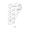
- FIG. 1 illustrates an example remote annunciator 10 that includes an enclosure 11 and a control 12 within the enclosure 11.
- the control 12 receives signals S from a plurality of transfer switches 13A, 13B, 13C, 13D and at least one generator 14 that is connected to at least one of the transfer switches 13A, 13B, 13C, 13D.
- the control 12 displays a status of electrical connections that include the plurality of transfer switches 13A, 13B, 13C, 13D and the at least one generator 14.
- control 12 recognizes when the plurality of transfer switches 13A, 13B, 13C, 13D and the at least one generator 14 are connected to the control 12.
- the control 12 is connected to the plurality of transfer switches 13A, 13B, 13C, 13D and the at least one generator 14 via a wired connection W.
- the control 12 sends out signals S to the plurality of transfer switches 13A, 13B, 13C, 13D and the at least one generator 14 via the wired connection W to determine a status of the plurality of transfer switches 13A, 13B, 13C, 13D and the at least one generator 14.
- the control 12 sends signals to the plurality of transfer switches 13A, 13B, 13C, 13D and the at least one generator 14 via the wired connection W to determine a status of the electrical connections that include the plurality of transfer switches 13A, 13B, 13C, 13D and the at least one generator 14.
- control 12 may be connected to the plurality of transfer switches 13A, 13B, 13C, 13D and the at least one generator 14 via a wired ModBus RTU connection.
- control 12 may be connected to the plurality of transfer switches 13A, 13B, 13C, 13D and the at least one generator 14 via a wired ModBus TCP connection.
- control 12 broadcasts signals S (see FIG. 2 ) to the plurality of transfer switches 13A, 13B, 13C, 13D and the at least one generator 14 via an Ethernet UDP connection to determine a status of the electrical connections that include the plurality of transfer switches 13A, 13B, 13C, 13D and the at least one generator 14.
- the control 12 may be connected to the plurality of transfer switches 13A, 13B, 13C, 13D and the at least one generator 14 via a wireless connection.
- the control 12 receives wireless signals from the plurality of transfer switches 13A, 13B, 13C, 13D and the at least one generator 14 via the wireless connection to determine a status of the plurality of transfer switches 13A, 13B, 13C, 13D and the at least one generator 14.
- control 12 may receive signals from the plurality of transfer switches 13A, 13B, 13C, 13D and the at least one generator 14 to determine a status of the electrical connections that include the plurality of transfer switches 13A, 13B, 13C, 13D and the at least one generator 14.
- control 12 is connected to the plurality of transfer switches 13A, 13B, 13C, 13D and the at least one generator 14 via a wireless ModBus TCP connection.
- the remote annunciator 10 may further include an indicator 20 that displays a status of the electrical connections that include the plurality of transfer switches 13A, 13B, 13C, 13D and the at least one generator 14.
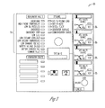
- an indicator 20 that may be provided with the remote annunciator 10 is shown in detail in FIG. 3 .
- the indicator 20 includes at least one LED that displays a status of the plurality of transfer switches 13A, 13B, 13C, 13D (4 are shown in FIG. 3 ) and the at least one generator 14 (one is shown in FIG. 3 ).
- the indicator 20 includes at least one LED that displays a status of the electrical connections that include plurality of transfer switches 13A, 13B, 13C, 13D (4 are shown in FIG. 3 ) and the at least one generator 14 (one is shown in FIG. 3 ).
- the indicator 20 includes at least one LCD (not shown) that displays a status of the plurality of transfer switches 13A, 13B, 13C, 13D and the at least one generator 14.
- the indicator 20 may include at least one LCD that displays a status of the electrical connections that include plurality of transfer switches 13A, 13B, 13C, 13D and the at least one generator 14.
- the remote annunciator 10 may further include further include a test button 25 that is connected to the control 12.
- the control 12 may simulate a power outage at any or more of the plurality of transfer switches 13A, 13B, 13C, 13D once the test button 25 is activated.
- the remote annunciator 10 further includes a plurality of test buttons 25 that are each connected to the control 12. The control 12 is able to simulate a power outage at a particular one of the plurality of transfer switches 13A, 13B, 13C, 13D once the test button 25 that is associated with the particular one of the plurality of transfer switches 13A, 13B, 13C, 13D is activated.
- the remote annunciator includes a selector switch (not shown in FIGS.) that is connected to the control 12.
- the control 12 may simulate a power outage at a particular one of the plurality of transfer switches 13A, 13B, 13C, 13D based on the position of the selector switch once the singular test button 25 is activated.
- the remote annunciators 10 described herein offer support for multiple ATS units and at least one genset. Therefore, multiple remote annunciators are not required in order to adequately monitor multiple ATS's and gensets. Therefore, the remote annunciators 10 described herein reduce unwanted cost and complexity that are associated with remotely monitoring various electrical systems that include such components.
Landscapes
- Engineering & Computer Science (AREA)
- Power Engineering (AREA)
- Business, Economics & Management (AREA)
- Emergency Management (AREA)
- Selective Calling Equipment (AREA)
Claims (15)
- Fernmelder (10), umfassend:- ein Gehäuse (11); und- eine Steuerung (12) innerhalb des Gehäuses (11),
wobei die Steuerung (12) eingerichtet ist,- um Signale von einer Mehrzahl von Umschaltern (13A-13D) und zumindest einem Generator (14) zu empfangen, der mit zumindest einem der Umschalter (13A-13D) verbunden ist,- um einen Status von elektrischen Verbindungen darzustellen, die die Mehrzahl von Umschaltern (13A-13D) und dem zumindest einen Generator (14) umfassen,
dadurch gekennzeichnet, dass die Steuerung ferner eingerichtet ist:- um Signale zur Mehrzahl von Umschaltern (13A-13D) und dem zumindest einen Generator (14) über eine Verbindung zu senden, um einen Status der Mehrzahl von Umschaltern (13A-13D) und des zumindest einen Generators (14) zu bestimmen. - Fernmelder (10) gemäß Anspruch 1, wobei die Steuerung (12) eingerichtet ist, um zu erkennen, wenn die Mehrzahl von Umschaltern (13A-13D) und der zumindest eine Generator (14) mit der Steuerung (12) verbunden sind.
- Fernmelder (10) gemäß Anspruch 1 oder 2, wobei die Steuerung (12) mit der Mehrzahl von Umschaltern (13A-13D) und dem zumindest einen Generator (14) über eine Kabelverbindung verbunden ist.
- Fernmelder (10) gemäß einem der Ansprüche 1 bis 3, wobei die Steuerung (12) eingerichtet ist, um Signale an die Mehrzahl von Umschaltern (13A-13D) und den zumindest einen Generator (14) zu senden und um einen Status der Mehrzahl von Umschaltern (13A-13D) und des zumindest einen Generators(14) zu bestimmen oder um einen Status der elektrischen Verbindungen zu bestimmen, die die Mehrzahl von Umschaltern (13A-13D) und den zumindest einen Generator (14) umfassen.
- Fernmelder (10) gemäß einem der Ansprüche 1 bis 4, wobei die Steuerung (12) mit der Mehrzahl von Umschaltern (13A-13D) und dem zumindest einen Generator (14) über eine kabelgebundene ModBus-RTU-Verbindung oder über eine kabelgebundene ModBus-TCP-Verbindung verbunden ist.
- Fernmelder (10) gemäß Anspruch 1 oder 2, wobei die Steuerung (12) mit der Mehrzahl von Umschaltern (13A-13D) und dem zumindest einen Generator (14) über eine kabellose Verbindung verbunden ist.
- Fernmelder (10) gemäß Anspruch 6, wobei die Steuerung (12) eingerichtet ist, um Funksignale von der Mehrzahl von Umschaltern (13A-13D) und dem zumindest einen Generator (14) über die drahtlose Verbindung zu empfangen und um einen Status der Mehrzahl von Umschaltern (13A-13D) und des zumindest einen Generators (14) zu bestimmen oder um einen Status der elektrischen Verbindungen zu bestimmen, die die Mehrzahl von Umschaltern (13A-13D) und den zumindest einen Generator (14) umfassen.
- Fernmelder (10) gemäß Anspruch 6 oder 7, wobei die Steuerung (12) mit der Mehrzahl von Umschaltern (13A-13D) und dem zumindest einen Generator (14) über eine drahtlose ModBus-TCP-Verbindung verbunden ist.
- Fernmelder (10) gemäß Anspruch 1, wobei die Steuerung (12) eingerichtet ist, um Signale zur Mehrzahl von Umschaltern (13A-13D) und zu dem zumindest einen Generator (14) über eine Ethernet-UDP-Verbindung zu übertragen, um einen Status der elektrischen Verbindungen zu bestimmen, die die Mehrzahl von Umschaltern (13A-13D) und den zumindest einen Generator (14) umfassen.
- Fernmelder (10) gemäß Anspruch 1, der ferner eine Anzeige (20) aufweist, die eingerichtet ist, um einen Status der elektrischen Verbindungen darzustellen, die die Mehrzahl von Umschaltern (13A-13D) und den zumindest einen Generator (14) umfassen.
- Fernmelder (10) gemäß Anspruch 10, wobei die Anzeige (20) zumindest eine LED umfasst, die eingerichtet ist, um einen Status der Mehrzahl von Umschaltern (13A-13D) und des zumindest einen Generators (14) oder einen Status der elektrischen Verbindungen darzustellen, die die Mehrzahl von Umschaltern (13A-13D) und den zumindest einen Generator (14) umfassen.
- Fernmelder (10) gemäß Anspruch 10, wobei die Anzeige zumindest eine LCD umfasst, die eingerichtet ist, um einen Status der Mehrzahl von Umschaltern (13A-13D) und des zumindest einen Generators (14) oder einen Status der elektrischen Verbindungen darzustellen, die die Mehrzahl von Umschaltern (13A-13D) und den zumindest einen Generator (14) umfassen.
- Fernmelder (10) gemäß einem der Ansprüche 1 bis 12, der ferner einen Testtaster aufweist, der mit der Steuerung (12) verbunden ist, wobei die Steuerung (12) eingerichtet ist, um einen Stromausfall in einem der Mehrzahl von Umschaltern (13A-13D) zu simulieren, sobald der Testtaster aktiviert ist.
- Fernmelder (10) gemäß einem der Ansprüche 1 bis 12, der ferner eine Mehrzahl von Testtastern aufweist, die jeweils mit der Steuerung (12) verbunden sind, wobei die Steuerung (12) eingerichtet ist, um einen Stromausfall in einem Bestimmten der Mehrzahl von Umschaltern (13A-13D) zu simulieren, sobald der Testtaster aktiviert ist, der mit dem bestimmten Umschalter der Mehrzahl von Umschaltern (13A-13D) verbunden ist.
- Fernmelder (10) gemäß einem der Ansprüche 1 bis 12, ferner umfassend:- einen Testtaster, der mit der Steuerung (12) verbunden ist; und- einen Wahlschalter, der mit der Steuerung (12) verbunden ist, wobei die Steuerung (12) eingerichtet ist, um einen Stromausfall in einem Bestimmten der Mehrzahl von Umschaltern (13A-13D) auf der Basis der Position des Wahlschalters zu simulieren, sobald der Testtaster aktiviert ist.
Applications Claiming Priority (1)
| Application Number | Priority Date | Filing Date | Title |
|---|---|---|---|
| US13/559,636 US8791814B2 (en) | 2012-07-27 | 2012-07-27 | Remote annunciator |
Publications (3)
| Publication Number | Publication Date |
|---|---|
| EP2690751A2 EP2690751A2 (de) | 2014-01-29 |
| EP2690751A3 EP2690751A3 (de) | 2014-03-19 |
| EP2690751B1 true EP2690751B1 (de) | 2016-08-17 |
Family
ID=48998382
Family Applications (1)
| Application Number | Title | Priority Date | Filing Date |
|---|---|---|---|
| EP13003628.8A Active EP2690751B1 (de) | 2012-07-27 | 2013-07-18 | Fernmelder |
Country Status (3)
| Country | Link |
|---|---|
| US (1) | US8791814B2 (de) |
| EP (1) | EP2690751B1 (de) |
| CN (1) | CN103576087B (de) |
Families Citing this family (1)
| Publication number | Priority date | Publication date | Assignee | Title |
|---|---|---|---|---|
| US9876351B2 (en) | 2016-01-28 | 2018-01-23 | Toshiba Tec Kabushiki Kaisha | Electric apparatus and power control method |
Family Cites Families (17)
| Publication number | Priority date | Publication date | Assignee | Title |
|---|---|---|---|---|
| US4672227A (en) | 1986-03-17 | 1987-06-09 | Westinghouse Electric Corp. | Automatic transfer switch with delay |
| US6163088A (en) * | 1999-09-30 | 2000-12-19 | Caterpillar Inc. | Method and apparatus for providing standby power from a generator using capacitor supplied voltage |
| US6876103B2 (en) | 2000-12-29 | 2005-04-05 | General Electric Company | Automatic transfer switch systems and controllers |
| US7362696B2 (en) | 2002-10-21 | 2008-04-22 | General Electric Company | Method and apparatus for automatic transfer switch |
| US20050141154A1 (en) * | 2003-12-03 | 2005-06-30 | Atwood Industries, Inc. | Power averaging and power load management system |
| US7889089B1 (en) | 2004-08-04 | 2011-02-15 | Bollin Daniel L | Auxiliary generator self-test verification device |
| US7436287B1 (en) | 2004-08-04 | 2008-10-14 | Bollin Daniel L | Auxiliary generator self-test verification device |
| US20060028069A1 (en) | 2004-08-09 | 2006-02-09 | Loucks David G | Retrofit kit for converting a transfer switch to a switch for soft-load transfer, and soft-load power distribution system and method |
| US7569949B2 (en) | 2007-01-26 | 2009-08-04 | Eaton Corporation | Transfer switch with generator maintenance indicator |
| US20080179967A1 (en) | 2007-01-26 | 2008-07-31 | Eaton Corporation | Transfer Switch With Generator Runtime Counter |
| US8222548B2 (en) | 2008-07-30 | 2012-07-17 | Generac Power Systems, Inc. | Automatic transfer switch |
| US8639953B2 (en) | 2009-03-27 | 2014-01-28 | Schneider Electric It Corporation | System and method for gathering information using a power device wherein information is associated with at least one external load |
| US8350405B2 (en) * | 2010-01-18 | 2013-01-08 | Generac Power Systems, Inc. | Load control module for a generator and method of operation |
| US8373569B2 (en) * | 2010-05-27 | 2013-02-12 | Briggs & Stratton Corporation | Power line carrier (PLC) communication of standby generator status |
| ES2941889T3 (es) | 2010-11-02 | 2023-05-26 | Schneider Electric Usa Inc | Sistema de distribución eléctrica fiable con fuente de potencia alternativa |
| US9103895B2 (en) | 2010-11-02 | 2015-08-11 | Schneider Electric USA, Inc. | Automated emergency power supply test using engine exhaust temperature |
| CN202150735U (zh) * | 2011-07-27 | 2012-02-22 | 常熟开关制造有限公司(原常熟开关厂) | 转换开关的控制器 |
-
2012
- 2012-07-27 US US13/559,636 patent/US8791814B2/en active Active
-
2013
- 2013-07-18 EP EP13003628.8A patent/EP2690751B1/de active Active
- 2013-07-24 CN CN201310314065.9A patent/CN103576087B/zh active Active
Also Published As
| Publication number | Publication date |
|---|---|
| CN103576087A (zh) | 2014-02-12 |
| CN103576087B (zh) | 2016-09-07 |
| EP2690751A2 (de) | 2014-01-29 |
| US20140028452A1 (en) | 2014-01-30 |
| EP2690751A3 (de) | 2014-03-19 |
| US8791814B2 (en) | 2014-07-29 |
Similar Documents
| Publication | Publication Date | Title |
|---|---|---|
| KR101424088B1 (ko) | 현장데이터 수집장치와 경보 로직시퀀스 제어장치를 활용한 원자력발전소 이중화 경보시스템 | |
| KR20160056540A (ko) | 수배전반 유지보수를 위한 감시제어장치 및 방법 | |
| EP2690751B1 (de) | Fernmelder | |
| JP2014050117A (ja) | 報知モジュール、開閉器子局及び開閉器監視システム | |
| CN202550382U (zh) | 开关柜综合状态显示仪 | |
| KR100783503B1 (ko) | 변전소 운영상태 감시를 위한 디지탈 축소형 모자익 배전반 | |
| CN211653128U (zh) | 气象雷达遥控及故障诊断装置 | |
| JP4481693B2 (ja) | 電流監視装置 | |
| EP3132318B1 (de) | Mobile mensch-maschinen-schnittstelle für steuergeräte | |
| KR100825359B1 (ko) | 변전소 운영상태 감시를 위한 디지탈 축소형 모자익배전반의 마스터씨피유 이중화구조 | |
| KR20180115451A (ko) | 보호 계전 상태를 표시하는 디지털 배전 장치 | |
| WO2011119202A3 (en) | Systems for monitoring power consumption | |
| TWI524621B (zh) | 電源管理系統及其控制方法 | |
| JP6253244B2 (ja) | 監視制御装置及び監視システム | |
| KR20080003282U (ko) | 배전반 통합 감시장치 | |
| CN201698191U (zh) | 智能电器控制开关 | |
| CN204793825U (zh) | 一种无线测温开关柜智能操作面板 | |
| JP2017108482A (ja) | 分電盤システム | |
| JP2013092853A (ja) | 道路管制センターシステムの子局側監視・制御装置 | |
| KR20110104831A (ko) | 배전반 환경감시기 | |
| US20240162745A1 (en) | Improved signalling solutions for electrical installations | |
| CN102437520A (zh) | 配电柜控制线路板 | |
| KR200426630Y1 (ko) | 변전소 운영상태 감시를 위한 디지탈 축소형 모자익배전반의 마스터씨피유 이중화구조 | |
| CN202058033U (zh) | 一种具有指示灯参数回显装置的工业控制设备 | |
| CN205429879U (zh) | 程控智能低压抽出式开关柜 |
Legal Events
| Date | Code | Title | Description |
|---|---|---|---|
| PUAI | Public reference made under article 153(3) epc to a published international application that has entered the european phase |
Free format text: ORIGINAL CODE: 0009012 |
|
| AK | Designated contracting states |
Kind code of ref document: A2 Designated state(s): AL AT BE BG CH CY CZ DE DK EE ES FI FR GB GR HR HU IE IS IT LI LT LU LV MC MK MT NL NO PL PT RO RS SE SI SK SM TR |
|
| AX | Request for extension of the european patent |
Extension state: BA ME |
|
| PUAL | Search report despatched |
Free format text: ORIGINAL CODE: 0009013 |
|
| AK | Designated contracting states |
Kind code of ref document: A3 Designated state(s): AL AT BE BG CH CY CZ DE DK EE ES FI FR GB GR HR HU IE IS IT LI LT LU LV MC MK MT NL NO PL PT RO RS SE SI SK SM TR |
|
| AX | Request for extension of the european patent |
Extension state: BA ME |
|
| RIC1 | Information provided on ipc code assigned before grant |
Ipc: H02J 13/00 20060101AFI20140211BHEP Ipc: H02J 9/06 20060101ALI20140211BHEP |
|
| 17P | Request for examination filed |
Effective date: 20140912 |
|
| RBV | Designated contracting states (corrected) |
Designated state(s): AL AT BE BG CH CY CZ DE DK EE ES FI FR GB GR HR HU IE IS IT LI LT LU LV MC MK MT NL NO PL PT RO RS SE SI SK SM TR |
|
| 17Q | First examination report despatched |
Effective date: 20150706 |
|
| REG | Reference to a national code |
Ref country code: DE Ref legal event code: R079 Ref document number: 602013010369 Country of ref document: DE Free format text: PREVIOUS MAIN CLASS: H02J0013000000 Ipc: H02J0009080000 |
|
| GRAP | Despatch of communication of intention to grant a patent |
Free format text: ORIGINAL CODE: EPIDOSNIGR1 |
|
| RIC1 | Information provided on ipc code assigned before grant |
Ipc: H02J 9/08 20060101AFI20160118BHEP Ipc: H02J 9/06 20060101ALI20160118BHEP |
|
| INTG | Intention to grant announced |
Effective date: 20160216 |
|
| GRAS | Grant fee paid |
Free format text: ORIGINAL CODE: EPIDOSNIGR3 |
|
| GRAA | (expected) grant |
Free format text: ORIGINAL CODE: 0009210 |
|
| AK | Designated contracting states |
Kind code of ref document: B1 Designated state(s): AL AT BE BG CH CY CZ DE DK EE ES FI FR GB GR HR HU IE IS IT LI LT LU LV MC MK MT NL NO PL PT RO RS SE SI SK SM TR |
|
| REG | Reference to a national code |
Ref country code: GB Ref legal event code: FG4D |
|
| REG | Reference to a national code |
Ref country code: CH Ref legal event code: EP |
|
| REG | Reference to a national code |
Ref country code: IE Ref legal event code: FG4D |
|
| REG | Reference to a national code |
Ref country code: AT Ref legal event code: REF Ref document number: 821888 Country of ref document: AT Kind code of ref document: T Effective date: 20160915 |
|
| REG | Reference to a national code |
Ref country code: DE Ref legal event code: R096 Ref document number: 602013010369 Country of ref document: DE |
|
| REG | Reference to a national code |
Ref country code: NL Ref legal event code: MP Effective date: 20160817 |
|
| REG | Reference to a national code |
Ref country code: LT Ref legal event code: MG4D |
|
| REG | Reference to a national code |
Ref country code: AT Ref legal event code: MK05 Ref document number: 821888 Country of ref document: AT Kind code of ref document: T Effective date: 20160817 |
|
| PG25 | Lapsed in a contracting state [announced via postgrant information from national office to epo] |
Ref country code: NL Free format text: LAPSE BECAUSE OF FAILURE TO SUBMIT A TRANSLATION OF THE DESCRIPTION OR TO PAY THE FEE WITHIN THE PRESCRIBED TIME-LIMIT Effective date: 20160817 Ref country code: IT Free format text: LAPSE BECAUSE OF FAILURE TO SUBMIT A TRANSLATION OF THE DESCRIPTION OR TO PAY THE FEE WITHIN THE PRESCRIBED TIME-LIMIT Effective date: 20160817 Ref country code: NO Free format text: LAPSE BECAUSE OF FAILURE TO SUBMIT A TRANSLATION OF THE DESCRIPTION OR TO PAY THE FEE WITHIN THE PRESCRIBED TIME-LIMIT Effective date: 20161117 Ref country code: RS Free format text: LAPSE BECAUSE OF FAILURE TO SUBMIT A TRANSLATION OF THE DESCRIPTION OR TO PAY THE FEE WITHIN THE PRESCRIBED TIME-LIMIT Effective date: 20160817 Ref country code: LT Free format text: LAPSE BECAUSE OF FAILURE TO SUBMIT A TRANSLATION OF THE DESCRIPTION OR TO PAY THE FEE WITHIN THE PRESCRIBED TIME-LIMIT Effective date: 20160817 Ref country code: FI Free format text: LAPSE BECAUSE OF FAILURE TO SUBMIT A TRANSLATION OF THE DESCRIPTION OR TO PAY THE FEE WITHIN THE PRESCRIBED TIME-LIMIT Effective date: 20160817 Ref country code: HR Free format text: LAPSE BECAUSE OF FAILURE TO SUBMIT A TRANSLATION OF THE DESCRIPTION OR TO PAY THE FEE WITHIN THE PRESCRIBED TIME-LIMIT Effective date: 20160817 |
|
| PG25 | Lapsed in a contracting state [announced via postgrant information from national office to epo] |
Ref country code: PL Free format text: LAPSE BECAUSE OF FAILURE TO SUBMIT A TRANSLATION OF THE DESCRIPTION OR TO PAY THE FEE WITHIN THE PRESCRIBED TIME-LIMIT Effective date: 20160817 Ref country code: ES Free format text: LAPSE BECAUSE OF FAILURE TO SUBMIT A TRANSLATION OF THE DESCRIPTION OR TO PAY THE FEE WITHIN THE PRESCRIBED TIME-LIMIT Effective date: 20160817 Ref country code: PT Free format text: LAPSE BECAUSE OF FAILURE TO SUBMIT A TRANSLATION OF THE DESCRIPTION OR TO PAY THE FEE WITHIN THE PRESCRIBED TIME-LIMIT Effective date: 20161219 Ref country code: SE Free format text: LAPSE BECAUSE OF FAILURE TO SUBMIT A TRANSLATION OF THE DESCRIPTION OR TO PAY THE FEE WITHIN THE PRESCRIBED TIME-LIMIT Effective date: 20160817 Ref country code: AT Free format text: LAPSE BECAUSE OF FAILURE TO SUBMIT A TRANSLATION OF THE DESCRIPTION OR TO PAY THE FEE WITHIN THE PRESCRIBED TIME-LIMIT Effective date: 20160817 Ref country code: LV Free format text: LAPSE BECAUSE OF FAILURE TO SUBMIT A TRANSLATION OF THE DESCRIPTION OR TO PAY THE FEE WITHIN THE PRESCRIBED TIME-LIMIT Effective date: 20160817 Ref country code: GR Free format text: LAPSE BECAUSE OF FAILURE TO SUBMIT A TRANSLATION OF THE DESCRIPTION OR TO PAY THE FEE WITHIN THE PRESCRIBED TIME-LIMIT Effective date: 20161118 |
|
| PG25 | Lapsed in a contracting state [announced via postgrant information from national office to epo] |
Ref country code: EE Free format text: LAPSE BECAUSE OF FAILURE TO SUBMIT A TRANSLATION OF THE DESCRIPTION OR TO PAY THE FEE WITHIN THE PRESCRIBED TIME-LIMIT Effective date: 20160817 Ref country code: RO Free format text: LAPSE BECAUSE OF FAILURE TO SUBMIT A TRANSLATION OF THE DESCRIPTION OR TO PAY THE FEE WITHIN THE PRESCRIBED TIME-LIMIT Effective date: 20160817 |
|
| REG | Reference to a national code |
Ref country code: DE Ref legal event code: R097 Ref document number: 602013010369 Country of ref document: DE |
|
| PG25 | Lapsed in a contracting state [announced via postgrant information from national office to epo] |
Ref country code: BE Free format text: LAPSE BECAUSE OF FAILURE TO SUBMIT A TRANSLATION OF THE DESCRIPTION OR TO PAY THE FEE WITHIN THE PRESCRIBED TIME-LIMIT Effective date: 20160817 Ref country code: SK Free format text: LAPSE BECAUSE OF FAILURE TO SUBMIT A TRANSLATION OF THE DESCRIPTION OR TO PAY THE FEE WITHIN THE PRESCRIBED TIME-LIMIT Effective date: 20160817 Ref country code: CZ Free format text: LAPSE BECAUSE OF FAILURE TO SUBMIT A TRANSLATION OF THE DESCRIPTION OR TO PAY THE FEE WITHIN THE PRESCRIBED TIME-LIMIT Effective date: 20160817 Ref country code: DK Free format text: LAPSE BECAUSE OF FAILURE TO SUBMIT A TRANSLATION OF THE DESCRIPTION OR TO PAY THE FEE WITHIN THE PRESCRIBED TIME-LIMIT Effective date: 20160817 Ref country code: SM Free format text: LAPSE BECAUSE OF FAILURE TO SUBMIT A TRANSLATION OF THE DESCRIPTION OR TO PAY THE FEE WITHIN THE PRESCRIBED TIME-LIMIT Effective date: 20160817 Ref country code: BG Free format text: LAPSE BECAUSE OF FAILURE TO SUBMIT A TRANSLATION OF THE DESCRIPTION OR TO PAY THE FEE WITHIN THE PRESCRIBED TIME-LIMIT Effective date: 20161117 |
|
| REG | Reference to a national code |
Ref country code: FR Ref legal event code: PLFP Year of fee payment: 5 |
|
| PLBE | No opposition filed within time limit |
Free format text: ORIGINAL CODE: 0009261 |
|
| STAA | Information on the status of an ep patent application or granted ep patent |
Free format text: STATUS: NO OPPOSITION FILED WITHIN TIME LIMIT |
|
| 26N | No opposition filed |
Effective date: 20170518 |
|
| PG25 | Lapsed in a contracting state [announced via postgrant information from national office to epo] |
Ref country code: SI Free format text: LAPSE BECAUSE OF FAILURE TO SUBMIT A TRANSLATION OF THE DESCRIPTION OR TO PAY THE FEE WITHIN THE PRESCRIBED TIME-LIMIT Effective date: 20160817 |
|
| REG | Reference to a national code |
Ref country code: CH Ref legal event code: PL |
|
| REG | Reference to a national code |
Ref country code: IE Ref legal event code: MM4A |
|
| PG25 | Lapsed in a contracting state [announced via postgrant information from national office to epo] |
Ref country code: LI Free format text: LAPSE BECAUSE OF NON-PAYMENT OF DUE FEES Effective date: 20170731 Ref country code: CH Free format text: LAPSE BECAUSE OF NON-PAYMENT OF DUE FEES Effective date: 20170731 Ref country code: IE Free format text: LAPSE BECAUSE OF NON-PAYMENT OF DUE FEES Effective date: 20170718 |
|
| REG | Reference to a national code |
Ref country code: FR Ref legal event code: PLFP Year of fee payment: 6 |
|
| PG25 | Lapsed in a contracting state [announced via postgrant information from national office to epo] |
Ref country code: LU Free format text: LAPSE BECAUSE OF NON-PAYMENT OF DUE FEES Effective date: 20170718 |
|
| PG25 | Lapsed in a contracting state [announced via postgrant information from national office to epo] |
Ref country code: MT Free format text: LAPSE BECAUSE OF NON-PAYMENT OF DUE FEES Effective date: 20170718 |
|
| PG25 | Lapsed in a contracting state [announced via postgrant information from national office to epo] |
Ref country code: AL Free format text: LAPSE BECAUSE OF FAILURE TO SUBMIT A TRANSLATION OF THE DESCRIPTION OR TO PAY THE FEE WITHIN THE PRESCRIBED TIME-LIMIT Effective date: 20160817 |
|
| PG25 | Lapsed in a contracting state [announced via postgrant information from national office to epo] |
Ref country code: MC Free format text: LAPSE BECAUSE OF FAILURE TO SUBMIT A TRANSLATION OF THE DESCRIPTION OR TO PAY THE FEE WITHIN THE PRESCRIBED TIME-LIMIT Effective date: 20160817 Ref country code: HU Free format text: LAPSE BECAUSE OF FAILURE TO SUBMIT A TRANSLATION OF THE DESCRIPTION OR TO PAY THE FEE WITHIN THE PRESCRIBED TIME-LIMIT; INVALID AB INITIO Effective date: 20130718 |
|
| PG25 | Lapsed in a contracting state [announced via postgrant information from national office to epo] |
Ref country code: CY Free format text: LAPSE BECAUSE OF NON-PAYMENT OF DUE FEES Effective date: 20160817 |
|
| PG25 | Lapsed in a contracting state [announced via postgrant information from national office to epo] |
Ref country code: MK Free format text: LAPSE BECAUSE OF FAILURE TO SUBMIT A TRANSLATION OF THE DESCRIPTION OR TO PAY THE FEE WITHIN THE PRESCRIBED TIME-LIMIT Effective date: 20160817 |
|
| PG25 | Lapsed in a contracting state [announced via postgrant information from national office to epo] |
Ref country code: TR Free format text: LAPSE BECAUSE OF FAILURE TO SUBMIT A TRANSLATION OF THE DESCRIPTION OR TO PAY THE FEE WITHIN THE PRESCRIBED TIME-LIMIT Effective date: 20160817 |
|
| PG25 | Lapsed in a contracting state [announced via postgrant information from national office to epo] |
Ref country code: IS Free format text: LAPSE BECAUSE OF FAILURE TO SUBMIT A TRANSLATION OF THE DESCRIPTION OR TO PAY THE FEE WITHIN THE PRESCRIBED TIME-LIMIT Effective date: 20161217 |
|
| P01 | Opt-out of the competence of the unified patent court (upc) registered |
Effective date: 20230707 |
|
| REG | Reference to a national code |
Ref country code: GB Ref legal event code: 732E Free format text: REGISTERED BETWEEN 20240725 AND 20240731 |
|
| REG | Reference to a national code |
Ref country code: DE Ref legal event code: R081 Ref document number: 602013010369 Country of ref document: DE Owner name: DISCOVERY ENERGY, LLC, KOHLER, US Free format text: FORMER OWNER: KOHLER CO., KOHLER, WIS., US |
|
| PGFP | Annual fee paid to national office [announced via postgrant information from national office to epo] |
Ref country code: GB Payment date: 20250513 Year of fee payment: 13 |
|
| PGFP | Annual fee paid to national office [announced via postgrant information from national office to epo] |
Ref country code: DE Payment date: 20250728 Year of fee payment: 13 |
|
| PGFP | Annual fee paid to national office [announced via postgrant information from national office to epo] |
Ref country code: FR Payment date: 20250725 Year of fee payment: 13 |