EP2690741A1 - Adapter, and vehicle and method for supplying power using same - Google Patents
Adapter, and vehicle and method for supplying power using same Download PDFInfo
- Publication number
- EP2690741A1 EP2690741A1 EP11861454.4A EP11861454A EP2690741A1 EP 2690741 A1 EP2690741 A1 EP 2690741A1 EP 11861454 A EP11861454 A EP 11861454A EP 2690741 A1 EP2690741 A1 EP 2690741A1
- Authority
- EP
- European Patent Office
- Prior art keywords
- power
- charging cable
- adapter
- signal
- vehicle
- Prior art date
- Legal status (The legal status is an assumption and is not a legal conclusion. Google has not performed a legal analysis and makes no representation as to the accuracy of the status listed.)
- Granted
Links
- 238000000034 method Methods 0.000 title claims description 69
- 230000007274 generation of a signal involved in cell-cell signaling Effects 0.000 claims abstract description 54
- 238000006243 chemical reaction Methods 0.000 claims abstract description 53
- 230000004044 response Effects 0.000 claims abstract description 20
- 230000005540 biological transmission Effects 0.000 claims description 11
- 238000002485 combustion reaction Methods 0.000 claims description 5
- 230000008569 process Effects 0.000 description 60
- 230000010355 oscillation Effects 0.000 description 54
- 238000010586 diagram Methods 0.000 description 25
- 230000003247 decreasing effect Effects 0.000 description 21
- 238000012840 feeding operation Methods 0.000 description 11
- 230000004048 modification Effects 0.000 description 9
- 238000012986 modification Methods 0.000 description 9
- 239000000872 buffer Substances 0.000 description 7
- 238000001514 detection method Methods 0.000 description 6
- 239000003990 capacitor Substances 0.000 description 5
- 101150049032 ACL1 gene Proteins 0.000 description 4
- 101100448894 Arabidopsis thaliana GLR3.1 gene Proteins 0.000 description 4
- 101100054598 Hordeum vulgare ACL1.2 gene Proteins 0.000 description 4
- 101150023061 acpP gene Proteins 0.000 description 4
- 230000008859 change Effects 0.000 description 4
- 239000000446 fuel Substances 0.000 description 2
- 230000001172 regenerating effect Effects 0.000 description 2
- HBBGRARXTFLTSG-UHFFFAOYSA-N Lithium ion Chemical compound [Li+] HBBGRARXTFLTSG-UHFFFAOYSA-N 0.000 description 1
- 239000002253 acid Substances 0.000 description 1
- 230000000694 effects Effects 0.000 description 1
- 230000001747 exhibiting effect Effects 0.000 description 1
- 229910001416 lithium ion Inorganic materials 0.000 description 1
- 230000007246 mechanism Effects 0.000 description 1
- 229910052987 metal hydride Inorganic materials 0.000 description 1
- 238000010248 power generation Methods 0.000 description 1
- 238000002360 preparation method Methods 0.000 description 1
Images


Classifications
-
- B—PERFORMING OPERATIONS; TRANSPORTING
- B60—VEHICLES IN GENERAL
- B60L—PROPULSION OF ELECTRICALLY-PROPELLED VEHICLES; SUPPLYING ELECTRIC POWER FOR AUXILIARY EQUIPMENT OF ELECTRICALLY-PROPELLED VEHICLES; ELECTRODYNAMIC BRAKE SYSTEMS FOR VEHICLES IN GENERAL; MAGNETIC SUSPENSION OR LEVITATION FOR VEHICLES; MONITORING OPERATING VARIABLES OF ELECTRICALLY-PROPELLED VEHICLES; ELECTRIC SAFETY DEVICES FOR ELECTRICALLY-PROPELLED VEHICLES
- B60L53/00—Methods of charging batteries, specially adapted for electric vehicles; Charging stations or on-board charging equipment therefor; Exchange of energy storage elements in electric vehicles
- B60L53/60—Monitoring or controlling charging stations
- B60L53/68—Off-site monitoring or control, e.g. remote control
-
- B—PERFORMING OPERATIONS; TRANSPORTING
- B60—VEHICLES IN GENERAL
- B60L—PROPULSION OF ELECTRICALLY-PROPELLED VEHICLES; SUPPLYING ELECTRIC POWER FOR AUXILIARY EQUIPMENT OF ELECTRICALLY-PROPELLED VEHICLES; ELECTRODYNAMIC BRAKE SYSTEMS FOR VEHICLES IN GENERAL; MAGNETIC SUSPENSION OR LEVITATION FOR VEHICLES; MONITORING OPERATING VARIABLES OF ELECTRICALLY-PROPELLED VEHICLES; ELECTRIC SAFETY DEVICES FOR ELECTRICALLY-PROPELLED VEHICLES
- B60L3/00—Electric devices on electrically-propelled vehicles for safety purposes; Monitoring operating variables, e.g. speed, deceleration or energy consumption
- B60L3/0023—Detecting, eliminating, remedying or compensating for drive train abnormalities, e.g. failures within the drive train
- B60L3/0069—Detecting, eliminating, remedying or compensating for drive train abnormalities, e.g. failures within the drive train relating to the isolation, e.g. ground fault or leak current
-
- B—PERFORMING OPERATIONS; TRANSPORTING
- B60—VEHICLES IN GENERAL
- B60L—PROPULSION OF ELECTRICALLY-PROPELLED VEHICLES; SUPPLYING ELECTRIC POWER FOR AUXILIARY EQUIPMENT OF ELECTRICALLY-PROPELLED VEHICLES; ELECTRODYNAMIC BRAKE SYSTEMS FOR VEHICLES IN GENERAL; MAGNETIC SUSPENSION OR LEVITATION FOR VEHICLES; MONITORING OPERATING VARIABLES OF ELECTRICALLY-PROPELLED VEHICLES; ELECTRIC SAFETY DEVICES FOR ELECTRICALLY-PROPELLED VEHICLES
- B60L3/00—Electric devices on electrically-propelled vehicles for safety purposes; Monitoring operating variables, e.g. speed, deceleration or energy consumption
- B60L3/04—Cutting off the power supply under fault conditions
-
- B—PERFORMING OPERATIONS; TRANSPORTING
- B60—VEHICLES IN GENERAL
- B60L—PROPULSION OF ELECTRICALLY-PROPELLED VEHICLES; SUPPLYING ELECTRIC POWER FOR AUXILIARY EQUIPMENT OF ELECTRICALLY-PROPELLED VEHICLES; ELECTRODYNAMIC BRAKE SYSTEMS FOR VEHICLES IN GENERAL; MAGNETIC SUSPENSION OR LEVITATION FOR VEHICLES; MONITORING OPERATING VARIABLES OF ELECTRICALLY-PROPELLED VEHICLES; ELECTRIC SAFETY DEVICES FOR ELECTRICALLY-PROPELLED VEHICLES
- B60L50/00—Electric propulsion with power supplied within the vehicle
- B60L50/10—Electric propulsion with power supplied within the vehicle using propulsion power supplied by engine-driven generators, e.g. generators driven by combustion engines
- B60L50/16—Electric propulsion with power supplied within the vehicle using propulsion power supplied by engine-driven generators, e.g. generators driven by combustion engines with provision for separate direct mechanical propulsion
-
- B—PERFORMING OPERATIONS; TRANSPORTING
- B60—VEHICLES IN GENERAL
- B60L—PROPULSION OF ELECTRICALLY-PROPELLED VEHICLES; SUPPLYING ELECTRIC POWER FOR AUXILIARY EQUIPMENT OF ELECTRICALLY-PROPELLED VEHICLES; ELECTRODYNAMIC BRAKE SYSTEMS FOR VEHICLES IN GENERAL; MAGNETIC SUSPENSION OR LEVITATION FOR VEHICLES; MONITORING OPERATING VARIABLES OF ELECTRICALLY-PROPELLED VEHICLES; ELECTRIC SAFETY DEVICES FOR ELECTRICALLY-PROPELLED VEHICLES
- B60L50/00—Electric propulsion with power supplied within the vehicle
- B60L50/40—Electric propulsion with power supplied within the vehicle using propulsion power supplied by capacitors
-
- B—PERFORMING OPERATIONS; TRANSPORTING
- B60—VEHICLES IN GENERAL
- B60L—PROPULSION OF ELECTRICALLY-PROPELLED VEHICLES; SUPPLYING ELECTRIC POWER FOR AUXILIARY EQUIPMENT OF ELECTRICALLY-PROPELLED VEHICLES; ELECTRODYNAMIC BRAKE SYSTEMS FOR VEHICLES IN GENERAL; MAGNETIC SUSPENSION OR LEVITATION FOR VEHICLES; MONITORING OPERATING VARIABLES OF ELECTRICALLY-PROPELLED VEHICLES; ELECTRIC SAFETY DEVICES FOR ELECTRICALLY-PROPELLED VEHICLES
- B60L53/00—Methods of charging batteries, specially adapted for electric vehicles; Charging stations or on-board charging equipment therefor; Exchange of energy storage elements in electric vehicles
- B60L53/10—Methods of charging batteries, specially adapted for electric vehicles; Charging stations or on-board charging equipment therefor; Exchange of energy storage elements in electric vehicles characterised by the energy transfer between the charging station and the vehicle
- B60L53/14—Conductive energy transfer
- B60L53/16—Connectors, e.g. plugs or sockets, specially adapted for charging electric vehicles
-
- B—PERFORMING OPERATIONS; TRANSPORTING
- B60—VEHICLES IN GENERAL
- B60L—PROPULSION OF ELECTRICALLY-PROPELLED VEHICLES; SUPPLYING ELECTRIC POWER FOR AUXILIARY EQUIPMENT OF ELECTRICALLY-PROPELLED VEHICLES; ELECTRODYNAMIC BRAKE SYSTEMS FOR VEHICLES IN GENERAL; MAGNETIC SUSPENSION OR LEVITATION FOR VEHICLES; MONITORING OPERATING VARIABLES OF ELECTRICALLY-PROPELLED VEHICLES; ELECTRIC SAFETY DEVICES FOR ELECTRICALLY-PROPELLED VEHICLES
- B60L53/00—Methods of charging batteries, specially adapted for electric vehicles; Charging stations or on-board charging equipment therefor; Exchange of energy storage elements in electric vehicles
- B60L53/10—Methods of charging batteries, specially adapted for electric vehicles; Charging stations or on-board charging equipment therefor; Exchange of energy storage elements in electric vehicles characterised by the energy transfer between the charging station and the vehicle
- B60L53/14—Conductive energy transfer
- B60L53/18—Cables specially adapted for charging electric vehicles
-
- B—PERFORMING OPERATIONS; TRANSPORTING
- B60—VEHICLES IN GENERAL
- B60L—PROPULSION OF ELECTRICALLY-PROPELLED VEHICLES; SUPPLYING ELECTRIC POWER FOR AUXILIARY EQUIPMENT OF ELECTRICALLY-PROPELLED VEHICLES; ELECTRODYNAMIC BRAKE SYSTEMS FOR VEHICLES IN GENERAL; MAGNETIC SUSPENSION OR LEVITATION FOR VEHICLES; MONITORING OPERATING VARIABLES OF ELECTRICALLY-PROPELLED VEHICLES; ELECTRIC SAFETY DEVICES FOR ELECTRICALLY-PROPELLED VEHICLES
- B60L53/00—Methods of charging batteries, specially adapted for electric vehicles; Charging stations or on-board charging equipment therefor; Exchange of energy storage elements in electric vehicles
- B60L53/60—Monitoring or controlling charging stations
- B60L53/62—Monitoring or controlling charging stations in response to charging parameters, e.g. current, voltage or electrical charge
-
- B—PERFORMING OPERATIONS; TRANSPORTING
- B60—VEHICLES IN GENERAL
- B60L—PROPULSION OF ELECTRICALLY-PROPELLED VEHICLES; SUPPLYING ELECTRIC POWER FOR AUXILIARY EQUIPMENT OF ELECTRICALLY-PROPELLED VEHICLES; ELECTRODYNAMIC BRAKE SYSTEMS FOR VEHICLES IN GENERAL; MAGNETIC SUSPENSION OR LEVITATION FOR VEHICLES; MONITORING OPERATING VARIABLES OF ELECTRICALLY-PROPELLED VEHICLES; ELECTRIC SAFETY DEVICES FOR ELECTRICALLY-PROPELLED VEHICLES
- B60L53/00—Methods of charging batteries, specially adapted for electric vehicles; Charging stations or on-board charging equipment therefor; Exchange of energy storage elements in electric vehicles
- B60L53/60—Monitoring or controlling charging stations
- B60L53/66—Data transfer between charging stations and vehicles
-
- B—PERFORMING OPERATIONS; TRANSPORTING
- B60—VEHICLES IN GENERAL
- B60L—PROPULSION OF ELECTRICALLY-PROPELLED VEHICLES; SUPPLYING ELECTRIC POWER FOR AUXILIARY EQUIPMENT OF ELECTRICALLY-PROPELLED VEHICLES; ELECTRODYNAMIC BRAKE SYSTEMS FOR VEHICLES IN GENERAL; MAGNETIC SUSPENSION OR LEVITATION FOR VEHICLES; MONITORING OPERATING VARIABLES OF ELECTRICALLY-PROPELLED VEHICLES; ELECTRIC SAFETY DEVICES FOR ELECTRICALLY-PROPELLED VEHICLES
- B60L55/00—Arrangements for supplying energy stored within a vehicle to a power network, i.e. vehicle-to-grid [V2G] arrangements
-
- B—PERFORMING OPERATIONS; TRANSPORTING
- B60—VEHICLES IN GENERAL
- B60L—PROPULSION OF ELECTRICALLY-PROPELLED VEHICLES; SUPPLYING ELECTRIC POWER FOR AUXILIARY EQUIPMENT OF ELECTRICALLY-PROPELLED VEHICLES; ELECTRODYNAMIC BRAKE SYSTEMS FOR VEHICLES IN GENERAL; MAGNETIC SUSPENSION OR LEVITATION FOR VEHICLES; MONITORING OPERATING VARIABLES OF ELECTRICALLY-PROPELLED VEHICLES; ELECTRIC SAFETY DEVICES FOR ELECTRICALLY-PROPELLED VEHICLES
- B60L7/00—Electrodynamic brake systems for vehicles in general
- B60L7/10—Dynamic electric regenerative braking
- B60L7/14—Dynamic electric regenerative braking for vehicles propelled by ac motors
-
- H—ELECTRICITY
- H01—ELECTRIC ELEMENTS
- H01R—ELECTRICALLY-CONDUCTIVE CONNECTIONS; STRUCTURAL ASSOCIATIONS OF A PLURALITY OF MUTUALLY-INSULATED ELECTRICAL CONNECTING ELEMENTS; COUPLING DEVICES; CURRENT COLLECTORS
- H01R31/00—Coupling parts supported only by co-operation with counterpart
- H01R31/06—Intermediate parts for linking two coupling parts, e.g. adapter
-
- H—ELECTRICITY
- H02—GENERATION; CONVERSION OR DISTRIBUTION OF ELECTRIC POWER
- H02J—CIRCUIT ARRANGEMENTS OR SYSTEMS FOR SUPPLYING OR DISTRIBUTING ELECTRIC POWER; SYSTEMS FOR STORING ELECTRIC ENERGY
- H02J13/00—Circuit arrangements for providing remote indication of network conditions, e.g. an instantaneous record of the open or closed condition of each circuitbreaker in the network; Circuit arrangements for providing remote control of switching means in a power distribution network, e.g. switching in and out of current consumers by using a pulse code signal carried by the network
- H02J13/00006—Circuit arrangements for providing remote indication of network conditions, e.g. an instantaneous record of the open or closed condition of each circuitbreaker in the network; Circuit arrangements for providing remote control of switching means in a power distribution network, e.g. switching in and out of current consumers by using a pulse code signal carried by the network characterised by information or instructions transport means between the monitoring, controlling or managing units and monitored, controlled or operated power network element or electrical equipment
- H02J13/00016—Circuit arrangements for providing remote indication of network conditions, e.g. an instantaneous record of the open or closed condition of each circuitbreaker in the network; Circuit arrangements for providing remote control of switching means in a power distribution network, e.g. switching in and out of current consumers by using a pulse code signal carried by the network characterised by information or instructions transport means between the monitoring, controlling or managing units and monitored, controlled or operated power network element or electrical equipment using a wired telecommunication network or a data transmission bus
-
- H—ELECTRICITY
- H02—GENERATION; CONVERSION OR DISTRIBUTION OF ELECTRIC POWER
- H02J—CIRCUIT ARRANGEMENTS OR SYSTEMS FOR SUPPLYING OR DISTRIBUTING ELECTRIC POWER; SYSTEMS FOR STORING ELECTRIC ENERGY
- H02J13/00—Circuit arrangements for providing remote indication of network conditions, e.g. an instantaneous record of the open or closed condition of each circuitbreaker in the network; Circuit arrangements for providing remote control of switching means in a power distribution network, e.g. switching in and out of current consumers by using a pulse code signal carried by the network
- H02J13/00032—Systems characterised by the controlled or operated power network elements or equipment, the power network elements or equipment not otherwise provided for
- H02J13/00036—Systems characterised by the controlled or operated power network elements or equipment, the power network elements or equipment not otherwise provided for the elements or equipment being or involving switches, relays or circuit breakers
-
- H—ELECTRICITY
- H02—GENERATION; CONVERSION OR DISTRIBUTION OF ELECTRIC POWER
- H02J—CIRCUIT ARRANGEMENTS OR SYSTEMS FOR SUPPLYING OR DISTRIBUTING ELECTRIC POWER; SYSTEMS FOR STORING ELECTRIC ENERGY
- H02J7/00—Circuit arrangements for charging or depolarising batteries or for supplying loads from batteries
-
- B—PERFORMING OPERATIONS; TRANSPORTING
- B60—VEHICLES IN GENERAL
- B60L—PROPULSION OF ELECTRICALLY-PROPELLED VEHICLES; SUPPLYING ELECTRIC POWER FOR AUXILIARY EQUIPMENT OF ELECTRICALLY-PROPELLED VEHICLES; ELECTRODYNAMIC BRAKE SYSTEMS FOR VEHICLES IN GENERAL; MAGNETIC SUSPENSION OR LEVITATION FOR VEHICLES; MONITORING OPERATING VARIABLES OF ELECTRICALLY-PROPELLED VEHICLES; ELECTRIC SAFETY DEVICES FOR ELECTRICALLY-PROPELLED VEHICLES
- B60L2210/00—Converter types
- B60L2210/40—DC to AC converters
-
- H—ELECTRICITY
- H02—GENERATION; CONVERSION OR DISTRIBUTION OF ELECTRIC POWER
- H02J—CIRCUIT ARRANGEMENTS OR SYSTEMS FOR SUPPLYING OR DISTRIBUTING ELECTRIC POWER; SYSTEMS FOR STORING ELECTRIC ENERGY
- H02J2207/00—Indexing scheme relating to details of circuit arrangements for charging or depolarising batteries or for supplying loads from batteries
- H02J2207/20—Charging or discharging characterised by the power electronics converter
-
- H—ELECTRICITY
- H02—GENERATION; CONVERSION OR DISTRIBUTION OF ELECTRIC POWER
- H02J—CIRCUIT ARRANGEMENTS OR SYSTEMS FOR SUPPLYING OR DISTRIBUTING ELECTRIC POWER; SYSTEMS FOR STORING ELECTRIC ENERGY
- H02J2310/00—The network for supplying or distributing electric power characterised by its spatial reach or by the load
- H02J2310/40—The network being an on-board power network, i.e. within a vehicle
- H02J2310/48—The network being an on-board power network, i.e. within a vehicle for electric vehicles [EV] or hybrid vehicles [HEV]
-
- H—ELECTRICITY
- H02—GENERATION; CONVERSION OR DISTRIBUTION OF ELECTRIC POWER
- H02J—CIRCUIT ARRANGEMENTS OR SYSTEMS FOR SUPPLYING OR DISTRIBUTING ELECTRIC POWER; SYSTEMS FOR STORING ELECTRIC ENERGY
- H02J7/00—Circuit arrangements for charging or depolarising batteries or for supplying loads from batteries
- H02J7/02—Circuit arrangements for charging or depolarising batteries or for supplying loads from batteries for charging batteries from ac mains by converters
-
- Y—GENERAL TAGGING OF NEW TECHNOLOGICAL DEVELOPMENTS; GENERAL TAGGING OF CROSS-SECTIONAL TECHNOLOGIES SPANNING OVER SEVERAL SECTIONS OF THE IPC; TECHNICAL SUBJECTS COVERED BY FORMER USPC CROSS-REFERENCE ART COLLECTIONS [XRACs] AND DIGESTS
- Y02—TECHNOLOGIES OR APPLICATIONS FOR MITIGATION OR ADAPTATION AGAINST CLIMATE CHANGE
- Y02B—CLIMATE CHANGE MITIGATION TECHNOLOGIES RELATED TO BUILDINGS, e.g. HOUSING, HOUSE APPLIANCES OR RELATED END-USER APPLICATIONS
- Y02B70/00—Technologies for an efficient end-user side electric power management and consumption
- Y02B70/30—Systems integrating technologies related to power network operation and communication or information technologies for improving the carbon footprint of the management of residential or tertiary loads, i.e. smart grids as climate change mitigation technology in the buildings sector, including also the last stages of power distribution and the control, monitoring or operating management systems at local level
-
- Y—GENERAL TAGGING OF NEW TECHNOLOGICAL DEVELOPMENTS; GENERAL TAGGING OF CROSS-SECTIONAL TECHNOLOGIES SPANNING OVER SEVERAL SECTIONS OF THE IPC; TECHNICAL SUBJECTS COVERED BY FORMER USPC CROSS-REFERENCE ART COLLECTIONS [XRACs] AND DIGESTS
- Y02—TECHNOLOGIES OR APPLICATIONS FOR MITIGATION OR ADAPTATION AGAINST CLIMATE CHANGE
- Y02B—CLIMATE CHANGE MITIGATION TECHNOLOGIES RELATED TO BUILDINGS, e.g. HOUSING, HOUSE APPLIANCES OR RELATED END-USER APPLICATIONS
- Y02B90/00—Enabling technologies or technologies with a potential or indirect contribution to GHG emissions mitigation
- Y02B90/20—Smart grids as enabling technology in buildings sector
-
- Y—GENERAL TAGGING OF NEW TECHNOLOGICAL DEVELOPMENTS; GENERAL TAGGING OF CROSS-SECTIONAL TECHNOLOGIES SPANNING OVER SEVERAL SECTIONS OF THE IPC; TECHNICAL SUBJECTS COVERED BY FORMER USPC CROSS-REFERENCE ART COLLECTIONS [XRACs] AND DIGESTS
- Y02—TECHNOLOGIES OR APPLICATIONS FOR MITIGATION OR ADAPTATION AGAINST CLIMATE CHANGE
- Y02E—REDUCTION OF GREENHOUSE GAS [GHG] EMISSIONS, RELATED TO ENERGY GENERATION, TRANSMISSION OR DISTRIBUTION
- Y02E60/00—Enabling technologies; Technologies with a potential or indirect contribution to GHG emissions mitigation
-
- Y—GENERAL TAGGING OF NEW TECHNOLOGICAL DEVELOPMENTS; GENERAL TAGGING OF CROSS-SECTIONAL TECHNOLOGIES SPANNING OVER SEVERAL SECTIONS OF THE IPC; TECHNICAL SUBJECTS COVERED BY FORMER USPC CROSS-REFERENCE ART COLLECTIONS [XRACs] AND DIGESTS
- Y02—TECHNOLOGIES OR APPLICATIONS FOR MITIGATION OR ADAPTATION AGAINST CLIMATE CHANGE
- Y02T—CLIMATE CHANGE MITIGATION TECHNOLOGIES RELATED TO TRANSPORTATION
- Y02T10/00—Road transport of goods or passengers
- Y02T10/60—Other road transportation technologies with climate change mitigation effect
- Y02T10/70—Energy storage systems for electromobility, e.g. batteries
-
- Y—GENERAL TAGGING OF NEW TECHNOLOGICAL DEVELOPMENTS; GENERAL TAGGING OF CROSS-SECTIONAL TECHNOLOGIES SPANNING OVER SEVERAL SECTIONS OF THE IPC; TECHNICAL SUBJECTS COVERED BY FORMER USPC CROSS-REFERENCE ART COLLECTIONS [XRACs] AND DIGESTS
- Y02—TECHNOLOGIES OR APPLICATIONS FOR MITIGATION OR ADAPTATION AGAINST CLIMATE CHANGE
- Y02T—CLIMATE CHANGE MITIGATION TECHNOLOGIES RELATED TO TRANSPORTATION
- Y02T10/00—Road transport of goods or passengers
- Y02T10/60—Other road transportation technologies with climate change mitigation effect
- Y02T10/7072—Electromobility specific charging systems or methods for batteries, ultracapacitors, supercapacitors or double-layer capacitors
-
- Y—GENERAL TAGGING OF NEW TECHNOLOGICAL DEVELOPMENTS; GENERAL TAGGING OF CROSS-SECTIONAL TECHNOLOGIES SPANNING OVER SEVERAL SECTIONS OF THE IPC; TECHNICAL SUBJECTS COVERED BY FORMER USPC CROSS-REFERENCE ART COLLECTIONS [XRACs] AND DIGESTS
- Y02—TECHNOLOGIES OR APPLICATIONS FOR MITIGATION OR ADAPTATION AGAINST CLIMATE CHANGE
- Y02T—CLIMATE CHANGE MITIGATION TECHNOLOGIES RELATED TO TRANSPORTATION
- Y02T10/00—Road transport of goods or passengers
- Y02T10/60—Other road transportation technologies with climate change mitigation effect
- Y02T10/72—Electric energy management in electromobility
-
- Y—GENERAL TAGGING OF NEW TECHNOLOGICAL DEVELOPMENTS; GENERAL TAGGING OF CROSS-SECTIONAL TECHNOLOGIES SPANNING OVER SEVERAL SECTIONS OF THE IPC; TECHNICAL SUBJECTS COVERED BY FORMER USPC CROSS-REFERENCE ART COLLECTIONS [XRACs] AND DIGESTS
- Y02—TECHNOLOGIES OR APPLICATIONS FOR MITIGATION OR ADAPTATION AGAINST CLIMATE CHANGE
- Y02T—CLIMATE CHANGE MITIGATION TECHNOLOGIES RELATED TO TRANSPORTATION
- Y02T90/00—Enabling technologies or technologies with a potential or indirect contribution to GHG emissions mitigation
- Y02T90/10—Technologies relating to charging of electric vehicles
- Y02T90/12—Electric charging stations
-
- Y—GENERAL TAGGING OF NEW TECHNOLOGICAL DEVELOPMENTS; GENERAL TAGGING OF CROSS-SECTIONAL TECHNOLOGIES SPANNING OVER SEVERAL SECTIONS OF THE IPC; TECHNICAL SUBJECTS COVERED BY FORMER USPC CROSS-REFERENCE ART COLLECTIONS [XRACs] AND DIGESTS
- Y02—TECHNOLOGIES OR APPLICATIONS FOR MITIGATION OR ADAPTATION AGAINST CLIMATE CHANGE
- Y02T—CLIMATE CHANGE MITIGATION TECHNOLOGIES RELATED TO TRANSPORTATION
- Y02T90/00—Enabling technologies or technologies with a potential or indirect contribution to GHG emissions mitigation
- Y02T90/10—Technologies relating to charging of electric vehicles
- Y02T90/14—Plug-in electric vehicles
-
- Y—GENERAL TAGGING OF NEW TECHNOLOGICAL DEVELOPMENTS; GENERAL TAGGING OF CROSS-SECTIONAL TECHNOLOGIES SPANNING OVER SEVERAL SECTIONS OF THE IPC; TECHNICAL SUBJECTS COVERED BY FORMER USPC CROSS-REFERENCE ART COLLECTIONS [XRACs] AND DIGESTS
- Y02—TECHNOLOGIES OR APPLICATIONS FOR MITIGATION OR ADAPTATION AGAINST CLIMATE CHANGE
- Y02T—CLIMATE CHANGE MITIGATION TECHNOLOGIES RELATED TO TRANSPORTATION
- Y02T90/00—Enabling technologies or technologies with a potential or indirect contribution to GHG emissions mitigation
- Y02T90/10—Technologies relating to charging of electric vehicles
- Y02T90/16—Information or communication technologies improving the operation of electric vehicles
- Y02T90/167—Systems integrating technologies related to power network operation and communication or information technologies for supporting the interoperability of electric or hybrid vehicles, i.e. smartgrids as interface for battery charging of electric vehicles [EV] or hybrid vehicles [HEV]
-
- Y—GENERAL TAGGING OF NEW TECHNOLOGICAL DEVELOPMENTS; GENERAL TAGGING OF CROSS-SECTIONAL TECHNOLOGIES SPANNING OVER SEVERAL SECTIONS OF THE IPC; TECHNICAL SUBJECTS COVERED BY FORMER USPC CROSS-REFERENCE ART COLLECTIONS [XRACs] AND DIGESTS
- Y04—INFORMATION OR COMMUNICATION TECHNOLOGIES HAVING AN IMPACT ON OTHER TECHNOLOGY AREAS
- Y04S—SYSTEMS INTEGRATING TECHNOLOGIES RELATED TO POWER NETWORK OPERATION, COMMUNICATION OR INFORMATION TECHNOLOGIES FOR IMPROVING THE ELECTRICAL POWER GENERATION, TRANSMISSION, DISTRIBUTION, MANAGEMENT OR USAGE, i.e. SMART GRIDS
- Y04S10/00—Systems supporting electrical power generation, transmission or distribution
- Y04S10/12—Monitoring or controlling equipment for energy generation units, e.g. distributed energy generation [DER] or load-side generation
- Y04S10/126—Monitoring or controlling equipment for energy generation units, e.g. distributed energy generation [DER] or load-side generation the energy generation units being or involving electric vehicles [EV] or hybrid vehicles [HEV], i.e. power aggregation of EV or HEV, vehicle to grid arrangements [V2G]
-
- Y—GENERAL TAGGING OF NEW TECHNOLOGICAL DEVELOPMENTS; GENERAL TAGGING OF CROSS-SECTIONAL TECHNOLOGIES SPANNING OVER SEVERAL SECTIONS OF THE IPC; TECHNICAL SUBJECTS COVERED BY FORMER USPC CROSS-REFERENCE ART COLLECTIONS [XRACs] AND DIGESTS
- Y04—INFORMATION OR COMMUNICATION TECHNOLOGIES HAVING AN IMPACT ON OTHER TECHNOLOGY AREAS
- Y04S—SYSTEMS INTEGRATING TECHNOLOGIES RELATED TO POWER NETWORK OPERATION, COMMUNICATION OR INFORMATION TECHNOLOGIES FOR IMPROVING THE ELECTRICAL POWER GENERATION, TRANSMISSION, DISTRIBUTION, MANAGEMENT OR USAGE, i.e. SMART GRIDS
- Y04S20/00—Management or operation of end-user stationary applications or the last stages of power distribution; Controlling, monitoring or operating thereof
- Y04S20/20—End-user application control systems
- Y04S20/242—Home appliances
-
- Y—GENERAL TAGGING OF NEW TECHNOLOGICAL DEVELOPMENTS; GENERAL TAGGING OF CROSS-SECTIONAL TECHNOLOGIES SPANNING OVER SEVERAL SECTIONS OF THE IPC; TECHNICAL SUBJECTS COVERED BY FORMER USPC CROSS-REFERENCE ART COLLECTIONS [XRACs] AND DIGESTS
- Y04—INFORMATION OR COMMUNICATION TECHNOLOGIES HAVING AN IMPACT ON OTHER TECHNOLOGY AREAS
- Y04S—SYSTEMS INTEGRATING TECHNOLOGIES RELATED TO POWER NETWORK OPERATION, COMMUNICATION OR INFORMATION TECHNOLOGIES FOR IMPROVING THE ELECTRICAL POWER GENERATION, TRANSMISSION, DISTRIBUTION, MANAGEMENT OR USAGE, i.e. SMART GRIDS
- Y04S30/00—Systems supporting specific end-user applications in the sector of transportation
- Y04S30/10—Systems supporting the interoperability of electric or hybrid vehicles
- Y04S30/12—Remote or cooperative charging
-
- Y—GENERAL TAGGING OF NEW TECHNOLOGICAL DEVELOPMENTS; GENERAL TAGGING OF CROSS-SECTIONAL TECHNOLOGIES SPANNING OVER SEVERAL SECTIONS OF THE IPC; TECHNICAL SUBJECTS COVERED BY FORMER USPC CROSS-REFERENCE ART COLLECTIONS [XRACs] AND DIGESTS
- Y04—INFORMATION OR COMMUNICATION TECHNOLOGIES HAVING AN IMPACT ON OTHER TECHNOLOGY AREAS
- Y04S—SYSTEMS INTEGRATING TECHNOLOGIES RELATED TO POWER NETWORK OPERATION, COMMUNICATION OR INFORMATION TECHNOLOGIES FOR IMPROVING THE ELECTRICAL POWER GENERATION, TRANSMISSION, DISTRIBUTION, MANAGEMENT OR USAGE, i.e. SMART GRIDS
- Y04S40/00—Systems for electrical power generation, transmission, distribution or end-user application management characterised by the use of communication or information technologies, or communication or information technology specific aspects supporting them
- Y04S40/12—Systems for electrical power generation, transmission, distribution or end-user application management characterised by the use of communication or information technologies, or communication or information technology specific aspects supporting them characterised by data transport means between the monitoring, controlling or managing units and monitored, controlled or operated electrical equipment
- Y04S40/124—Systems for electrical power generation, transmission, distribution or end-user application management characterised by the use of communication or information technologies, or communication or information technology specific aspects supporting them characterised by data transport means between the monitoring, controlling or managing units and monitored, controlled or operated electrical equipment using wired telecommunication networks or data transmission busses
Definitions
- the present invention relates to an adapter, and a vehicle and a method for performing power feeding using the adapter, and more specifically to a technique for supplying electric power generated by a vehicle to an external electrical device.
- a vehicle equipped with a power storage device for example, a secondary battery, a capacitor and the like
- a power storage device for example, a secondary battery, a capacitor and the like
- Such a vehicle includes, for example, an electric vehicle, a hybrid vehicle, a fuel-cell vehicle, and the like.
- hybrid vehicle there is also a known vehicle equipped with a power storage device that can be charged by a power supply external to the vehicle (hereinafter simply referred to as an "external power supply") as in the case of the electric vehicle (which will be hereinafter simply referred to as “external charging”).
- an “external power supply” a power supply external to the vehicle
- the so-called “plug-in hybrid vehicle” is known which is provided with a power storage device that can be charged by a household power supply through the charging cable connecting between the power receptacle provided in the house and the charging port provided in the vehicle. Accordingly, it can be expected to improve the fuel consumption efficiency of the hybrid vehicle.
- a vehicle As for such an externally chargeable vehicle, there has been developed a concept of supplying electric power from a vehicle, which is regarded as a power supply source, to a commonly-used electrical device external to the vehicle, as seen in the smart grid and the like. Furthermore, a vehicle may be used as a power supply for using an electrical device when working outdoors, in camping or the like.
- Japanese Patent Laying-Open No. 2010-035277 discloses a charge/discharge system in which, for a vehicle capable of charging a battery mounted therein using a charging cable, electric power from the vehicle can be supplied to an electric load external to the vehicle by using a power cable exclusively for power feeding, which is different from the charging cable, and to which a power plug of the electric load external to the vehicle can be connected.
- An object of the present invention is to provide, for an externally chargeable vehicle, a conversion adaptor for supplying electric power to an external electrical device from the vehicle using a power cable for charging.
- An adapter serves as an adapter used for supplying electric power from a power source including a power storage device mounted in an externally chargeable vehicle to an electrical device external to the vehicle through a charging cable, the vehicle using electric power supplied from an external power supply through the charging cable to charge the power storage device.
- the adapter includes a first connection unit capable of connecting a power plug of the charging cable to be connected to the external power supply during external charging; and a second connection unit electrically connected to the first connection unit and capable of connecting a power plug of the electrical device.
- the adapter further includes a signal generation unit configured to generate a signal instructing power feeding by connection between the adapter and the charging cable.
- the vehicle supplies the electric power from the power source to the electrical device through the charging cable connected to the vehicle.
- the vehicle includes a power conversion device for converting the electric power from the power source to supply the converted electric power to the charging cable, and a first control device for controlling the power conversion device.
- the charging cable includes a second control device capable of transmitting and receiving a signal to and from the first control device.
- the signal generation unit supplies, to the second control device, a signal showing the connection between the adapter and the charging cable to cause the second control device to output the signal instructing power feeding to the first control device.
- the first control device drives the power conversion device to supply the electric power from the power source to the electrical device.
- the signal generation unit changes a potential of a signal path connected to the second control device to supply the signal showing the connection between the adapter and the charging cable to the second control device.
- the signal generation unit includes a resistor and electrically connects the signal path to a ground through the resistor by connection between the adapter and the charging cable.
- the signal generation unit includes a switch and electrically connects the signal path to a ground via the switch by connection between the adapter and the charging cable.
- the charging cable includes a switching unit configured to switch between conduction and non-conduction between the signal path and a ground.
- the signal generation unit includes an operation member configured to allow a conducting state of the switching unit to be changed by connection between the adapter and the charging cable.
- the switching unit is a switch.
- the switch is in a conducting state in a state where the adapter and the charging cable are not connected.
- the operation member brings the switch into a non-conducting state by connection of the adapter to the charging cable.
- the signal generation unit outputs, to the second control device, a signal responding to reception of a signal transmitted from the second control device using a pair of power transmission paths in the charging cable as a signal showing connection between the adapter and the charging cable, to cause the second control device to output the signal instructing power feeding to the first control device.
- the signal generation unit includes a bypass circuit configured to branch a part of a high frequency signal transmitted from the second control device to one of the pair of power transmission paths, and output the branched signal to the second control device.
- the signal generation unit includes a filter circuit configured to cause a high frequency signal transmitted from the second control device to one of the pair of power transmission paths to pass through the other of the power transmission paths.
- the signal instructing power feeding is output from the second control device to the first control device, utilizing a pilot signal used for transmitting information about a current capacity of the charging cable, when performing external charging.
- the signal instructing power feeding is output using a frequency different from a frequency of the pilot signal used during external charging.
- the signal instructing power feeding is output using a potential different from a potential of the pilot signal used during external charging.
- the vehicle includes a power conversion device for converting the electric power from the power source to supply the converted electric power to the charging cable, and a control device for controlling the power conversion device.
- the signal generation unit outputs the signal instructing power feeding to the control device through a signal line included in the charging cable.
- the control device drives the power conversion device to supply the electric power from the power source to the electrical device.
- the signal generation unit outputs, to the control device, a signal responding to reception of a signal transmitted from the control device through a pair of power transmission paths of the charging cable as the signal instructing power feeding.
- a vehicle according to the present invention serves as a vehicle that is externally chargeable using electric power supplied from an external power supply through a charging cable to charge a power storage device mounted therein and is capable of feeding electric power to an external electrical device by connection of an adapter to the charging cable.
- the vehicle includes a power source including the power storage device; an inlet for connecting the charging cable during external charging; a power conversion device for converting electric power from the power source to supply the converted electric power to the inlet; and a first control device for controlling the power conversion device.
- the adapter includes a first connection unit capable of connecting a power plug of the charging cable to be connected to the external power supply during external charging, and a second connection unit electrically connected to the first connection unit and capable of connecting a power plug of the electrical device.
- the first control device drives the power conversion device to supply the electric power from the power source to the electrical device.
- the power source further includes an internal combustion engine, and a rotating electric machine configured to be driven by the internal combustion engine to generate electric power.
- the electric power generated by the rotating electric machine is supplied to the electrical device through the charging cable and the adapter.
- a method according to the present invention is a method for feeding electric power from a power source including a power storage device mounted in an externally chargeable vehicle to an external electrical device by connection of an adapter to a charging cable, in which the vehicle uses electric power supplied from an external power supply through the charging cable to charge the power storage device.
- the vehicle includes an inlet for connecting the charging cable during external charging, and a power conversion device for converting the electric power from the power source to supply the converted electric power to the inlet.
- the adapter includes a first connection unit capable of connecting a power plug of the charging cable to be connected to the external power supply during external charging, and a second connection unit electrically connected to the first connection unit and capable of connecting a power plug of the electrical device.
- the method includes the steps of: connecting the charging cable to the inlet; connecting the charging cable to the first connection unit of the adapter; connecting the power plug of the electrical device to the second connection unit of the adapter; receiving a signal instructing power feeding that is generated by connection between the adapter and the charging cable; and controlling the power conversion device in response to the signal instructing power feeding to supply the electric power from the power source to the electrical device.
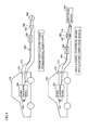
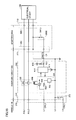
- Fig. 1 is a schematic diagram of a charging system in a vehicle 10 according to the first embodiment.
- the electric power from an external power supply 402 is used to charge a power storage device 150 mounted in vehicle 10.
- vehicle 10 is not particularly limited as long as it can run with electric power from the power storage device that can be charged by an external power supply.
- Vehicle 10 may be, for example, a hybrid vehicle, an electric vehicle, a fuel-cell vehicle, and the like. Also, the configuration of vehicle 10 is applicable to any vehicle that, for example, runs with an internal combustion engine as long as it is provided with a chargeable power storage device.
- vehicle 10 includes an inlet 270, a power conversion device 160, a relay 155, a power storage device 150, a drive unit 20, a vehicle ECU (Electronic Control Unit) 170, and a voltage sensor 182.
- Drive unit 20 includes a motor drive device 180, a motor generator (which will be hereinafter also referred to as an "MG") 120, a driving wheel 130, an engine 140, and a power split device 145.
- MG motor generator
- a connector 310 provided in a charging cable 300 is connected to inlet 270.
- Power conversion device 160 is connected to inlet 270 through power lines ACL1 and ACL2. Furthermore, power conversion device 160 is connected to power storage device 150 through relay 155. Based on a control signal PWE from vehicle ECU 170, power conversion device 160 converts alternating-current (AC) power supplied from a power supply 402 external to the vehicle into a direct-current (DC) power with which power storage device 150 can be charged. Then, power conversion device 160 supplies the converted DC power to power storage device 150.
- AC alternating-current
- DC direct-current
- Power storage device 150 is a chargeable and dischargeable electric power storage component.
- Power storage device 150 is configured to include, for example, a secondary battery such as a lithium-ion battery, a nickel-metal hydride battery or a lead acid battery, or a power storage element such as an electric double layer capacitor.
- Power storage device 150 stores the DC power supplied from power conversion device 160. Power storage device 150 is connected to motor drive device 180 driving MG 120, and supplies the DC power used for generating a driving force used for vehicle running. Furthermore, power storage device 150 stores the electric power generated by MG 120.
- power storage device 150 further includes a voltage sensor for detecting a voltage of power storage device 150 and a current sensor for detecting a current that is input to and output from power storage device 150. Power storage device 150 outputs the detection values of the voltage and the current detected by these sensors to vehicle ECU 170.
- Motor drive device 180 is connected to power storage device 150 and MG 120. Motor drive device 180 is controlled by vehicle ECU 170, to convert the electric power supplied from power storage device 150 into electric power for driving MG 120. Motor drive device 180 is configured, for example, to include a three-phase inverter.
- MG 120 is connected to motor drive device 180 and also connected through power split device 145 to a driving wheel 130. MG 120 receives electric power supplied from motor drive device 180 to generate a driving force used for causing vehicle 10 to run. While MG 120 receives rotating force from driving wheel 130 to generate AC power and generates regenerative braking force by a regenerative torque command from vehicle ECU 170. MG 120 is configured to include, for example, a three-phase AC motor generator including a rotor having a permanent magnet embedded therein and a stator having a Y-connected three-phase coil.
- MG 120 is connected also to engine 140 through power split device 145.
- Vehicle ECU 170 controls the driving forces of the engine and MG 120 to be set at an optimal ratio.
- MG 120 can also operate as a power generator.
- the electric power generated by MG 120 is stored in power storage device 150.
- the electric power generated by MG 120 may be supplied to electrical devices external to the vehicle through inlet 270 as described below.
- Voltage sensor 182 is connected between power lines ACL1 and ACL2, and detects a voltage of the electric power supplied from external power supply 402. Then, voltage sensor 182 outputs a detection value VAC of the voltage to vehicle ECU 170.
- Relay 155 is interposed in the path connecting power conversion device 160 and power storage device 150. Relay 155 is controlled by a control signal SE from vehicle ECU 170 to switch between supply and cut-off of the electric power between power conversion device 160 and power storage device 150.
- a control signal SE from vehicle ECU 170 to switch between supply and cut-off of the electric power between power conversion device 160 and power storage device 150.
- relay 155 may also be included in power storage device 150 or power conversion device 160.
- vehicle ECU 170 includes a CPU (Central Processing Unit), a storage device and an input/output buffer. Vehicle ECU 170 inputs the signal from each sensor and the like and outputs the control command to each device, and also controls vehicle 10 and each device.
- the control of these devices and the like is not limited to the process by means of software, but the process can be implemented by constructing dedicated hardware (an electronic circuit).
- Vehicle ECU 170 receives a connection signal CNCT and a pilot signal CPLT from charging cable 300 through inlet 270. Furthermore, vehicle ECU 170 receives voltage detection value VAC of the received electric power from voltage sensor 182.
- Vehicle ECU 170 receives inputs of detection values about a current, a voltage and a temperature from the sensor (not shown) installed within power storage device 150, to calculate the state amount showing the state of charge of power storage device 150 (which will be hereinafter also referred to as an "SOC (State of Charge)").
- SOC State of Charge
- vehicle ECU 170 controls power conversion device 160, relay 155 and the like for charging power storage device 150.
- Charging cable 300 includes a connector 310 provided at an end on the vehicle side; a plug 320 provided at an end on the external power supply side; a charging circuit interrupt device (which will be hereinafter also referred to as a "CCID") 330; and a power line unit 340 that connects between the devices and inputs/outputs electric power and a control signal.
- a charging circuit interrupt device which will be hereinafter also referred to as a "CCID"
- a power line unit 340 that connects between the devices and inputs/outputs electric power and a control signal.
- Power line unit 340 includes a power line unit 340A connecting between plug 320 and CCID 330, and a power line unit 340B connecting between connector 310 and CCID 330. Furthermore, power line unit 340 includes a power line 341 for transmitting electric power from external power supply 402.
- Charging cable 300 is connected to a receptacle 400 of external power supply 402 (for example, a commercial power supply) through plug 320 of charging cable 300. Furthermore, inlet 270 provided in the body of vehicle 10 and connector 310 of charging cable 300 are connected to each other to transmit the electric power to vehicle 10 from power supply 402 external to the vehicle. Charging cable 300 is detachable from and attachable to external power supply 402 and vehicle 10.
- external power supply 402 for example, a commercial power supply
- connection detecting circuit 312 detecting connection of connector 310 is provided within connector 310 and detects the state of connection between inlet 270 and connector 310.
- Connection detecting circuit 312 outputs connection signal CNCT showing the connection state to vehicle ECU 170 of vehicle 10 through inlet 270.
- Connection detecting circuit 312 may be configured as a limit switch as shown in Fig. 1 , so as to cause the potential of connection signal CNCT to be a ground potential (0V) when connector 310 is connected to inlet 270.
- connection detecting circuit 312 may be configured as a resistor (not shown) having a prescribed resistance value, so as to cause the potential of connection signal CNCT to be decreased to a prescribed potential at the time of connection.
- vehicle ECU 170 detects the potential of connection signal CNCT to thereby detect that connector 310 has been connected to inlet 270.
- CCID 330 includes a CCID relay 332 and a control pilot circuit 334.
- CCID relay 332 is interposed in a power line 341 within charging cable 300.
- CCID relay 332 is controlled by control pilot circuit 334.
- control pilot circuit 334 When CCID relay 332 is opened, the electric path is cut off within charging cable 300.
- CCID relay 332 is closed, the electric power is supplied from external power supply 402 to vehicle 10.
- Control pilot circuit 334 outputs pilot signal CPLT to vehicle ECU 170 through connector 310 and inlet 270.
- This pilot signal CPLT serves as a signal from control pilot circuit 334 for notifying vehicle ECU 170 about the rated current of charging cable 300.
- pilot signal CPLT also serves as a signal used for remote-controlling CCID relay 332 by vehicle ECU 170 based on the potential of pilot signal CPLT controlled by vehicle ECU 170.
- control pilot circuit 334 controls CCID relay 332 based on the change in the potential of pilot signal CPLT.
- pilot signal CPLT and connection signal CNCT and the configuration such as a shape and a terminal arrangement of inlet 270, connector 310 and the like are standardized, for example, by SAE (Society of Automotive Engineers) in the U.S., Japan Electric Vehicle Association, and the like.
- SAE Society of Automotive Engineers
- Fig. 2 is a diagram for illustrating the charging circuit shown in Fig. 1 in greater detail.
- description of the components designated by the same reference characters as those in Fig. 1 will not be repeated.
- CCID 330 further includes an electromagnetic coil 606, a leakage detector 608, a CCID control unit 610, a battery 615, a voltage sensor 650, and a current sensor 660.
- control pilot circuit 334 includes an oscillation device 602, a resistance R20 and a voltage sensor 604.
- CCID control unit 610 includes a CPU, a storage device and an input/output buffer, and inputs/outputs the signals of each sensor and control pilot circuit 334 while controlling the charging operation of charging cable 300.
- CCID control unit 610 is supplied with a power supply from battery 615 incorporated in CCID 330.
- oscillation device 602 When the potential of pilot signal CPLT detected by voltage sensor 604 is a prescribed potential (for example, 12V), oscillation device 602 outputs a non-oscillating signal. When the potential of pilot signal CPLT is decreased from the prescribed potential as mentioned above (for example, 9V), oscillation device 602 is controlled by CCID control unit 610, to output the signal oscillating at a prescribed frequency (for example, 1 kHz) and in a prescribed duty cycle.
- a prescribed potential for example, 12V
- oscillation device 602 When the potential of pilot signal CPLT is decreased from the prescribed potential as mentioned above (for example, 9V), oscillation device 602 is controlled by CCID control unit 610, to output the signal oscillating at a prescribed frequency (for example, 1 kHz) and in a prescribed duty cycle.
- pilot signal CPLT is controlled by vehicle ECU 170, as will be described with reference to Fig. 3 .
- the duty cycle is set based on the rated current that can be supplied from external power supply 402 through charging cable 300 to vehicle 10.
- pilot signal CPLT oscillates in a prescribed cycle.
- the pulse width of pilot signal CPLT is set. In other words, by the duty shown by the ratio of the pulse width to this oscillation cycle, vehicle ECU 170 of vehicle 10 is notified of the rated current by pilot signal CPLT from control pilot circuit 334.
- the rated current is set for each charging cable, the rated current differs according to the types of charging cable 300. Therefore, the duty of pilot signal CPLT also differs according to the types of charging cable 300.
- vehicle ECU 170 Based on the duty of pilot signal CPLT received through a control pilot line L1, vehicle ECU 170 can detect the rated current that can be supplied to vehicle 10 through charging cable 300.
- control pilot circuit 334 supplies a current to electromagnetic coil 606.
- electromagnetic coil 606 When receiving a current from control pilot circuit 334, electromagnetic coil 606 generates an electromagnetic force and closes the contact of CCID relay 332 to bring about a conducting state.
- Leakage detector 608 is provided in the middle of power line 341 of charging cable 300 within CCID 330, and detects whether leakage occurs or not. Specifically, leakage detector 608 detects the equilibrium state of the current flowing through a pair of power lines 341 in the directions opposite to each other. Then, when the equilibrium state is disturbed, leakage detector 608 detects occurrence of leakage. Although not particularly shown, when leakage detector 608 detects leakage, power feeding to electromagnetic coil 606 is cut off and the contact of CCID relay 332 is opened to bring about a non-conducting state.
- voltage sensor 650 detects the power supply voltage transmitted from external power supply 402, and notifies CCID control unit 610 of the detection value. Furthermore, current sensor 660 detects the charging current flowing through power line 341, and notifies CCID control unit 610 of the detection value.
- Connection detecting circuit 312 included within connector 310 is, for example, a limit switch as described above, in which case the contact is closed in the state where connector 310 is connected to inlet 270 while the contact is opened in the state where connector 310 is disconnected from inlet 270.
- connection signal line L3 is short-circuited to a ground line L2, with the result that the potential on connection signal line L3 becomes a ground potential (0V).
- connection detecting circuit 312 can also be a resistor (not shown). In this case, in the state where connector 310 is connected to inlet 270, a voltage signal determined by the voltage on power supply node 511, pull-up resistance R10 and this resistor is generated on connection signal line L3.
- connection detecting circuit 312 is a limit switch or a resistor as described above, the potential generated on connection signal line L3 (that is, the potential of connection signal CNCT) varies between the time when connector 310 is connected to inlet 270 and the time when connector 310 is disconnected from inlet 270. Therefore, vehicle ECU 170 can detect the connection state of connector 310 by detecting the potential of connection signal line L3.
- vehicle ECU 170 in addition to power supply node 511 and pull-up resistance R10 described above, vehicle ECU 170 further includes a resistance circuit 502, input buffers 504, 506, and a CPU 508.
- Resistance circuit 502 includes pull-down resistances R1, R2, and switches SW1 and SW2.
- Pull-down resistance R1 and switch SW1 are connected in series between a vehicle ground 512 and control pilot line L1 through which pilot signal CPLT is communicated.
- Pull-down resistance R2 and switch SW2 are also connected in series between control pilot line L1 and vehicle ground 512.
- Switches SW1 and SW2 are controlled in accordance with control signals S1 and S2, respectively, from CPU 508 to be brought into a conducting state or a non-conducting state.
- This resistance circuit 502 serves to control the potential of pilot signal CPLT from the vehicle 10 side.
- Input buffer 504 receives pilot signal CPLT on control pilot line L1, and outputs the received pilot signal CPLT to CPU 508.
- Input buffer 506 receives connection signal CNCT through connection signal line L3 connected to connection detecting circuit 312 of connector 310, and outputs the received connection signal CNCT to CPU 508.
- vehicle ECU 170 applies a voltage to connection signal line L3, and the potential of connection signal CNCT is changed by connection of connector 310 to inlet 270.
- CPU 508 detects the potential of this connection signal CNCT, thereby detecting the connection state of connector 310.
- CPU 508 receives pilot signal CPLT and connection signal CNCT from input buffers 504 and 506, respectively.
- CPU 508 detects the potential of connection signal CNCT, and detects the connection state of connector 310.
- CPU 508 detects the oscillation state and the duty cycle of pilot signal CPLT, thereby detecting the rated current of charging cable 300 as described above.
- CPU 508 controls control signals S1 and S2 of switches SW1 and SW2, respectively, thereby controlling the potential of pilot signal CPLT. Consequently, CPU 508 can remotely operate CCID relay 332. Then, electric power is transmitted from external power supply 402 to vehicle 10 through charging cable 300.
- CPU 508 when the contact of CCID relay 332 is closed, the AC power from external power supply 402 is supplied to power conversion device 160, and then, the preparation for charging power storage device 150 from external power supply 402 is completed.
- CPU 508 outputs a control signal PWE to power conversion device 160, thereby converting the AC power from external power supply 402 into a DC power that can be supplied to power storage device 150. Then, CPU 508 outputs control signal SE and closes the contact of relay 155, thereby charging power storage device 150.
- Fig. 3 is a time chart for illustrating charging control in the charging system in Fig. 2 .
- the horizontal axis shows time while the vertical axis shows the state of connection of plug 320 to external power supply 402, the potential of pilot signal CPLT, the potential of connection signal CNCT, the states of switches SW1 and SW2, the state of CCID relay 332, and the execution state of the charging process.
- charging cable 300 is not connected to vehicle 10 and external power supply 402 until time t10.
- switches SW1, SW2 and CCID relay 332 are in the OFF state while the potential of pilot signal CPLT is 0V.
- the potential of connection signal CNCT is V11 (> 0V).
- control pilot circuit 334 generates pilot signal CPLT.
- connector 310 of charging cable 300 is not connected to inlet 270 at this time t10. Also, the potential of pilot signal CPLT is V1 (for example, 12V) while pilot signal CPLT is in the non-oscillation state.
- connection signal CNCT detects that the potential of connection signal CNCT has been decreased, thereby detecting connection between connector 310 and inlet 270.
- control signal S1 is activated by CPU 508, and switch SW1 is turned on.
- the potential of pilot signal CPLT is decreased to V2 (for example, 9V) by pull-down resistance R1 of resistance circuit 502.
- CPU 508 When detecting that pilot signal CPLT has been oscillated, CPU 508 detects the rated current of charging cable 300 by the duty of pilot signal CPLT as described above.
- CPU 508 activates control signal S2 to turn on switch SW2.
- the potential of pilot signal CPLT is decreased to V3 (for example, 6V) by pull-down resistance R2 (time t13 in Fig. 3 ).
- CCID control unit 610 detects that the potential of this pilot signal CPLT has been decreased to V3
- the contact of CCID relay 332 is closed at time t14, to transmit the electric power from external power supply 402 to vehicle 10 through charging cable 300.
- CPU 508 When charging of power storage device 150 proceeds and it is determined that power storage device 150 is fully charged, CPU 508 ends the charging process (time t16 in Fig. 3 ). Then, CPU 508 deactivates control signal S2, to bring switch SW2 into a non-conducting state (time t17 in Fig. 3 ). Consequently, the potential of pilot signal CPLT becomes V2, and accordingly, the charging process is stopped while CCID relay 332 is brought into a non-conducting state (time t18), thereby ending the charging operation. Then, CPU 508 deactivates control signal S1 to bring switch SW1 into a non-conducting state, thereby shutting down the system.
- a vehicle which is regarded as a power supply source
- electrical devices and power networks external to the vehicle are supplied to electrical devices and power networks external to the vehicle.
- a vehicle may be used as a power supply for using an electrical device when working outdoors, in camping or the like.
- a conversion adapter 800 is provided as shown in the lower section in Fig. 4 .
- plug 320 of charging cable 300 used during external charging and a power plug 710 of an electrical device 700 external to the vehicle can be connected.
- this conversion adapter 800 allows the electric power from vehicle 10 to be supplied to electrical device 700 external to the vehicle through charging cable 300 (which will be hereinafter referred to as "power feeding to outside").
- power conversion device 160 of vehicle 10 converts the DC power stored in power storage device 150 serving as a power source into AC power that can be used in electrical device 700 (for example, AC 100V, 200V and the like), and the converted power is supplied to electrical device 700.
- examples of a power source of vehicle 10 include engine 140 and motor generator 120 in the case of a hybrid vehicle provided with engine 140 as shown in Fig. 1 .
- the electric power (AC power) generated by engine 140 driving motor generator 120 is converted by motor drive device 180 and power conversion device 160 into AC power that can be used in electrical device 700. Then, the converted power is supplied to electrical device 700.
- AC power AC power
- vehicle 10 is a fuel-cell vehicle, it is also possible to supply the electric power generated by a fuel cell.
- power conversion device 160 in addition to the above-described function of converting the electric power from external power supply 402 into charge power for power storage device 150, power conversion device 160 should have a function of converting the electric power stored in vehicle 10 and/or the electric power generated in vehicle 10 into driving electric power for external electrical device 700.
- one power conversion device capable of bidirectionally converting electric power between external charging and power feeding to outside may be provided, or a power conversion device exclusively for external charging and a power conversion device exclusively for power feeding to outside may be separately provided.
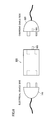
- Fig. 5 is a schematic diagram showing an example of adapter 800 used during power feeding to outside, as described with reference to Fig. 4 .
- adapter 800 includes a connection unit 801 for connecting plug 320 of charging cable 300 and a connection unit 805 for connecting power plug 710 of external electrical device 700.
- Connection unit 801 on the charging cable 300 side is provided with a terminal unit 802 to which the terminal of plug 320 is connected. Also, connection unit 801 is further provided with a terminal 803 for transmitting a signal showing connection between adapter 800 and plug 320. As shown in Fig. 6 , plug 320 is provided with a terminal unit 322 accommodating terminal 803. When plug 320 and adapter 800 are connected to each other, terminal 803 and terminal unit 322 are electrically coupled.
- connection unit 805 on the electrical device 700 side is provided with a terminal unit 806 corresponding to the terminal shape of power plug 710 of electrical device 700.
- Terminal unit 806 has a shape that is, for example, adapted to a voltage (100V, 200V and the like) to be used and the standards specified in the country in which this terminal unit is to be used.
- Fig. 5 shows an example in which connection units 801 and 805 are integrally structured and housed in the same housing, which may be however configured, for example as with an adapter 800# shown in Fig. 7 , such that a connector 810 on the charging cable 300 side and a connector 820 on the electrical device 700 side can be separated from each other, and coupled to each other through a cable 830 serving as a power transmission medium.
- Fig. 8 is a detailed diagram of a circuit in the case where adapter 800 according to the first embodiment is used for power feeding.
- the configuration of vehicle 10 is the same as that in Fig. 2 , and components in vehicle 10 and charging cable 300 are partially not shown in Fig. 8 .
- the same components as those in Fig. 2 will not be explained in Fig. 8 .
- adapter 800 includes a signal generation unit 850 in addition to connection units 801 and 805.
- signal generation unit 850 When plug 320 of charging cable 300 is connected to adapter 800, signal generation unit 850 is electrically connected to a signal line L4 of charging cable 300. When being connected to signal line L4, signal generation unit 850 supplies, to CCID control unit 610 of charging cable 300, a signal CNCT2 showing connection between charging cable 300 and adapter 800. While a specific example of signal generation unit 850 will be explained in and after Fig. 15 , signal generation unit 850 may be a control device having a CPU or may be a control circuit exhibiting a desired function. When signal generation unit 850 requires a power supply voltage for driving, the power supply voltage is supplied from the battery (not shown) incorporated in adapter 800.
- CCID control unit 610 determines whether or not charging cable 300 and adapter 800 are connected to each other. When determining that charging cable 300 and adapter 800 are connected to each other, CCID control unit 610 outputs pilot signal CPLT to vehicle ECU 170 using a frequency and/or a potential different from those during external charging. Consequently, CCID control unit 610 can cause vehicle ECU 170 to perform a power feeding operation.
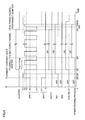
- Fig. 9 is a time chart for illustrating the power feeding control in the first embodiment.
- the horizontal axis shows time while the vertical axis shows the state of connection of adapter 800, the potential of pilot signal CPLT, the potential of connection signal CNCT, the state of connection signal CNCT2, the states of switches SW1 and SW2, the state of CCID relay 332, and the execution state of the power feeding process.
- charging cable 300 is not connected to inlet 270 until time t20.
- switches SW1, SW2 and CCID relay 332 are in the OFF state while the potential of pilot signal CPLT is 0V.
- the potential of connection signal CNCT is V11 (> 0V) while connection signal CNCT2 is in the OFF state.
- pilot signal CPLT is V1 (for example, 12V) and pilot signal CPLT is in a non-oscillation state.
- connection signal CNCT is decreased by connection detecting circuit 312.
- CPU 508 detects that the potential of connection signal CNCT has been decreased, thereby detecting that charging cable 300 has been connected to inlet 270.
- CPU 508 activates control signal S1 to thereby turn on switch SW1 (time t21).
- the potential of pilot signal CPLT is decreased to V2 (for example, 9V) by pull-down resistance R1 of resistance circuit 502.
- CCID control unit 610 recognizes that plug 320 of charging cable 300 has been connected to adapter 800.
- CCID control unit 610 closes CCID relay 332.
- CPU 508 detects that pilot signal CPLT has been oscillated. However, as described above, since an oscillation frequency Fsup of pilot signal CPLT output from CCID 330 during the power feeding operation is lower than an oscillation frequency Fchr during the charging operation, CPU 508 recognizes based on this difference between the oscillation frequencies that adapter 800 has been connected to charging cable 300 and that the power feeding operation has been instructed.
- CPU 508 closes the contact of relay 155 while controlling power conversion device 160 ( Fig. 1 ), thereby starting to supply electric power from power storage device 150 ( Fig. 1 ) to electrical device 700 (time t23).
- CCID control unit 610 stops the oscillation of pilot signal CPLT (time t25). In response to this, CPU 508 stops the power feeding process and also turns switch SW1 to be OFF (time t26). Then, CCID relay 332 is interrupted by CCID control unit 610 at time t27.
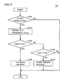
- Fig. 10 is a flowchart for illustrating a control process for selecting a frequency of pilot signal CPLT that is performed in CCID control unit 610 in the first embodiment.
- the process is implemented by executing the program stored in CCID control unit 610 in advance in predetermined cycles.
- the process can be implemented by constructing dedicated hardware (an electronic circuit).
- CCID control unit 610 obtains connection signal CNCT2 in step (which will be hereinafter abbreviated to S) 300. Then, CCID control unit 610 determines in S310 whether or not connection signal CNCT2 is ON, that is, whether or not charging cable 300 and adapter 800 are connected to each other. As described later, in the case where the potential of connection signal CNCT2 is changed due to connection between charging cable 300 and adapter 800, CCID control unit 610 determines in this S310 that connection signal CNCT2 has been turned ON, based on the fact that the potential of connection signal CNCT2 has been changed to a prescribed level.
- CCID control unit 610 When connection signal CNCT2 is OFF (NO in S310), CCID control unit 610 recognizes that adapter 800 is not connected to charging cable 300 and the normal external charging mode is employed. Then, in S330, CCID control unit 610 sets an oscillation frequency Fcplt of pilot signal CPLT at frequency Fchr for performing external charging, and oscillates pilot signal CPLT.
- CCID control unit 610 recognizes that adapter 800 is connected to charging cable 300 and the mode for power feeding to outside is employed. Then, in S320, CCID control unit 610 sets oscillation frequency Fcplt of pilot signal CPLT at frequency Fsup lower than frequency Fchr during external charging (Fsup ⁇ Fchr), and oscillates pilot signal CPLT.
- Fig. 11 is a flowchart for illustrating a control process for switching between a charging process and a power feeding process that is performed in vehicle ECU 170 in the first embodiment.
- the process is implemented by executing the program stored in CPU 508 of vehicle ECU 170 in advance in predetermined cycles.
- the process can be implemented by constructing dedicated hardware (an electronic circuit).
- CPU 508 determines in S100 whether or not pilot signal CPLT is oscillating.
- pilot signal CPLT is oscillating (YES in S100)
- CPU 508 recognizes that charging cable 300 is connected to inlet 270, and in S110, obtains oscillation frequency Fcplt of pilot signal CPLT.
- CPU 508 determines in S120 whether or not the obtained oscillation frequency Fcplt is equal to oscillation frequency Fchr in the case of the charging operation.
- the obtained oscillation frequency Fcplt does not need to be completely equal to oscillation frequency Fchr during the charging operation, and the difference between oscillation frequency Fcplt and oscillation frequency Fchr only needs to fall within a prescribed range (
- oscillation frequency Fcplt is not equal to oscillation frequency Fchr (NO in S120)
- the process proceeds to S 140, in which CPU 508 determines whether or not the obtained oscillation frequency Fcplt is equal to oscillation frequency Fsup during the power feeding operation. Also in this case, similarly to the case of determination in S120, the obtained oscillation frequency Fcplt does not need to be completely equal to oscillation frequency Fsup during the power feeding operation, and the difference between oscillation frequency Fcplt and oscillation frequency Fsup only needs to fall within a prescribed range (
- the electric power from the vehicle can be supplied to the electrical device external to the vehicle through the charging cable by using a conversion adaptor for a charging cable.
- oscillation frequency Fsup of pilot signal CPLT at the time when adapter 800 is connected to charging cable 300 is lower than oscillation frequency Fchr at the time when adapter 800 is not connected to charging cable 300 (that is, the oscillation cycle is relatively long).
- oscillation frequency Fsup may be set to be greater than oscillation frequency Fchr.
- Fig. 12 is a time chart for illustrating the control during power feeding in the modification of the first embodiment.
- the horizontal axis shows time while the vertical axis shows the state of connection of adapter 800, the potential of pilot signal CPLT, the potential of connection signal CNCT, the state of connection signal CNCT2, the states of switches SW1 and SW2, the state of CCID relay 332, and the execution state of the power feeding process.
- pilot signal CPLT when charging cable 300 is connected to inlet 270, CCID 330 generates pilot signal CPLT. It is to be noted that, at this time t30, the potential of pilot signal CPLT is V1 (for example, 12V) while pilot signal CPLT is in a non-oscillation state.
- CPU 508 detects that the potential of connection signal CNCT has been decreased, thereby detecting that charging cable 300 has been connected to inlet 270.
- CPU 508 activates control signal S1 to turn switch SW1 to be ON (time t31).
- the potential of pilot signal CPLT is decreased to V2 (for example, 9V) by pull-down resistance R1 of resistance circuit 502.
- CCID control unit 610 recognizes that plug 320 of charging cable 300 has been connected to adapter 800.
- CCID control unit 610 outputs the potential of pilot signal CPLT as a potential V4 (for example, 15V) greater than a potential V1 in the case where charging cable 300 is connected.
- CPU 508 of vehicle ECU 170 detects that the potential of pilot signal CPLT is V4, thereby recognizing that adapter 800 has been connected to charging cable 300.
- control signal S1 of switch SW1 may be kept activated or deactivated.
- CCID control unit 610 oscillates pilot signal CPLT. Since it can already be recognized based on the potential of pilot signal CPLT that adapter 800 is connected, the oscillation frequency at this time may be equal to oscillation cycle Tchr as in the case of external charging, or may be different therefrom. Then, CCID control unit 610 closes CCID relay 332.
- CPU 508 When CPU 508 detects oscillation of pilot signal CPLT, it controls relay 155 and power conversion device 160, thereby performing the operation for feeding electric power to electrical device 700 (time t33 in Fig. 12 ).
- CCID control unit 610 stops the oscillation of pilot signal CPLT.
- CPU 508 ends the power feeding process (time t35 in Fig. 12 ) while CCID control unit 610 opens CCID relay 332 (time t36 in Fig. 12 ).
- Fig. 13 is a flowchart for illustrating a control process for selecting a voltage of pilot signal CPLT that is performed in CCID control unit 610 in the modification of the first embodiment.
- Fig. 13 shows the same flowchart as that described in Fig. 10 in the first embodiment except that steps S320 and S330 are replaced with S320A and S330A, respectively. The same steps as those in Fig. 10 will not be repeated in Fig. 13 .
- connection signal CNCT2 is OFF, that is, adapter 800 is not connected to charging cable 300 (NO in S310)
- CCID control unit 610 sets, in S330A, a potential Vcplt of pilot signal CPLT at potential V1 for performing external charging, to oscillate pilot signal CPLT.
- connection signal CNCT2 is ON, that is, adapter 800 is connected to charging cable 300 (NO in S310)
- CCID control unit 610 sets, in S320A, potential Vcplt of pilot signal CPLT at potential V4 for performing power feeding to outside, to oscillate pilot signal CPLT.
- Fig. 14 is a flowchart for illustrating a control process for switching between the charging process and the power feeding process that is performed in vehicle ECU 170 in the modification of the first embodiment.
- CPU 508 determines in S200 whether or not the potential of connection signal CNCT is decreased.
- connection signal CNCT When the potential of connection signal CNCT is not decreased (NO in S200), charging cable 300 is not connected to inlet 270, and therefore, CPU 508 ends the process.
- connection signal CNCT When the potential of connection signal CNCT is decreased (YES in S200), the process proceeds to S210, in which CPU 508 obtains potential Vcplt of pilot signal CPLT.
- CPU 508 determines in S220 whether or not the obtained potential Vcplt is not more than potential V1 at the time of the charging operation (Vcplt ⁇ V1).
- the electric power from the vehicle can be supplied to the electrical device external to the vehicle through the charging cable by using a conversion adaptor for a charging cable.
- the signal generation unit included in the adapter is a control circuit serving to output an ON signal when the adapter and the charging cable are connected to each other, and output an OFF signal when the adapter and the charging cable are not connected to each other.
- variations of a specific example of the signal generation unit included in the adapter will be hereinafter described with reference to Figs. 15 to 22 .
- Fig. 15 is a diagram for illustrating an adapter 800A including a signal generation unit 850A having a resistance R30.
- an electric power is provided from a power supply node 616 to signal line L4 in charging cable 300 through a pull-up resistance R21.
- the potential of signal line L4 becomes a potential set by power supply node 616.
- signal line L4 When adapter 800A is connected to charging cable 300, signal line L4 is connected to a ground through resistance R30 included in signal generation unit 850A. This causes the potential of signal line L4 to be decreased to a potential that is obtained by dividing the potential on power supply node 616 by resistances R21 and R30.
- CCID control unit 610 detects such a change in the potential of signal line L4, thereby detecting that adapter 800A has been connected to charging cable 300.
- Fig. 16 is a diagram for illustrating an adapter 800B including a signal generation unit 850B having a switch SW10.
- an electric power is provided from power supply node 616 to signal line L4 in charging cable 300 through pull-up resistance R21, as in Fig. 15 .
- the potential of signal line L4 becomes a potential set by power supply node 616.
- signal line L4 is connected to a ground via switch SW10 included in signal generation unit 850B. This causes the potential of signal line L4 to be decreased to a ground potential.
- CCID control unit 610 detects such a change in the potential of signal line L4, thereby detecting that adapter 800B has been connected to charging cable 300.
- Fig. 17 is a diagram for illustrating an adapter 800C having an operation member 860 for operating switch 321 serving as a switching unit included in charging cable 300, as a signal generation unit.
- signal line L4 is connected to a ground within charging cable 300 via switch 321 included in plug 320. Furthermore, as in Fig. 15 , an electric power is provided from power supply node 616 to signal line L4 in charging cable 300 through pull-up resistance R21.
- switch 321 the contact is closed, for example, in the state where adapter 800C is not connected to charging cable 300. Therefore, when adapter 800C has not been connected, the potential of signal line L4 becomes a ground potential.
- Operation member 860 is, for example, a rod-shaped member and provided in place of terminal 803 shown in adapter 800 in Fig. 5 .
- operation member 860 directly or indirectly opens the contact of switch 321 within plug 320. This causes signal line L4 to be disconnected from a ground. Then, the potential of signal line L4 is increased from a ground potential to the potential set by power supply node 616.
- CCID control unit 610 detects such a change in the potential of signal line L4, thereby detecting that adapter 800C has been connected to charging cable 300.
- Fig. 17 shows the configuration in which switch 321 is closed when adapter 800C is not connected to charging cable 300 and opened when adapter 800C is connected to charging cable 300.
- switch 321 may be configured to be opened when adapter 800C is not connected to charging cable 300 and closed when adapter 800C is connected to charging cable 300.
- Fig. 18 is a diagram for illustrating an adapter 800D provided with a bypass circuit 870 as a signal generation unit.
- bypass circuit 870 is electrically connected between a ground and one of power lines 341 extending from vehicle 10 to electrical device 700. Furthermore, when adapter 800D is connected to charging cable 300, bypass circuit 870 is also connected to signal line L4 of charging cable 300.
- Bypass circuit 870 has a configuration, for example, like a circuit 871 shown in Fig. 19 or a circuit 872 shown in Fig. 20 .
- Circuit 871 shown in Fig. 19 includes resistances R50 and R51 that are connected in series between terminals 50 and 51 electrically connected to one of power lines 341 and signal line L4, respectively.
- the connection node of resistances R50 and R51 is connected to a ground.
- circuit 872 shown in Fig. 20 includes a coil L50, a capacitor C50 and a resistance R55 that are connected in series between terminal 50 and a ground.
- the connection node of capacitor C50 and resistance R55 is connected to terminal 51.
- CCID control unit 610 applies a high frequency signal Vin to the power line to which bypass circuit 870 is connected.
- a high frequency signal Vin is superimposed on its power supply voltage.
- Bypass circuit 870 generates a signal Vout corresponding to high frequency signal Vin by a circuit as shown in Figs. 19 and 20 . Then, this generated signal Vout is transmitted through signal line L4 to CCID control unit 610.
- CCID control unit 610 detects signal Vout generated by bypass circuit 870, thereby detecting that adapter 800D has been connected to charging cable 300.
- Fig. 21 is a flowchart for illustrating a control process for selecting a frequency of pilot signal CPLT that is performed in CCID control unit 610 in the case where bypass circuit 870 shown in Fig. 18 is used.
- CCID control unit 610 applies high frequency signal Vin to one of the power lines continuously or for each prescribed time period. Then, in S410, while being applying high frequency signal Vin, CCID control unit 610 detects whether or not output signal Vout from bypass circuit 870 exists in signal line L4.
- CCID control unit 610 When output signal Vout is not detected (NO in S410), CCID control unit 610 recognizes that adapter 800D is not connected to charging cable 300. Then, the process proceeds to S440, in which CCID control unit 610 sets oscillation frequency Fcplt of pilot signal CPLT at frequency Fchr for performing external charging, to oscillate pilot signal CPLT.
- CCID control unit 610 recognizes that adapter 800D has been connected to charging cable 300. Then, the process proceeds to S430, in which CCID control unit 610 sets oscillation frequency Fcplt of pilot signal CPLT at frequency Fsup lower than frequency Fchr (Fsup ⁇ Fchr) in the case of external charging, to oscillate pilot signal CPLT.
- Fig. 22 is a diagram for illustrating an adapter 800E provided with a filter circuit 870A as a signal generation unit.
- filter circuit 870A is electrically connected between power lines 341 that each connect vehicle 10 and electrical device 700.
- Filter circuit 870A is, for example, a high-pass filter or a bandpass filter through which the signal passes that has a specific frequency higher than the power supply frequency transmitted via power line 341. Accordingly, filter circuit 870A allows the high frequency signal applied to one of the power lines to pass through the other of the power lines.
- CCID control unit 610 applies a high frequency signal to one of the power lines.
- the applied high frequency signal is caused to pass through filter circuit 870A and appears on the other of power lines 341. Therefore, while being applying a high frequency signal to one of the power lines, CCID control unit 610 detects this high frequency signal in the other of the power lines, thereby detecting that adapter 800E is connected to charging cable 300.
- Fig. 23 is a detailed diagram of a circuit in the case where electric power is supplied through a charging cable 300A by using an adapter 800F in the second embodiment.
- charging cable 300A does not have CCID 330 as in charging cable 300 described in the first embodiment. Accordingly, pilot signal CPLT is not input to CPU 508 of vehicle ECU 170.
- vehicle ECU 170 When performing external charging in such a configuration, vehicle ECU 170 generally determines whether or not the charging operation is performed based on connection signal CNCT and also on existence or non-existence of the power supply voltage supplied between power lines ACL1 and ACL2 from the external power supply.
- a signal generation unit 850C included in adapter 800F is directly connected to CPU 508 of vehicle ECU 170 through a signal line L5 within charging cable 300A, and supplies connection signal CNCT2 to CPU 508. Based on connection signal CNCT2, CPU 508 detects that adapter 800F is connected to charging cable 300A, and switches between the charging operation and the power feeding operation.
- Fig. 24 is a flowchart for illustrating a control process for switching between the charging process and the power feeding process that is performed in vehicle ECU 170 in the second embodiment.
- CPU 508 of vehicle ECU 170 obtains connection signal CNCT2 from adapter 800F.
- CPU 508 determines whether or not connection signal CNCT2 is ON.
- connection signal CNCT2 is OFF (NO in S510)
- the process proceeds to S530, in which CPU 508 performs the charging process.
- connection signal CNCT2 is ON (YES in S510)
- the process proceeds to S520, in which CPU 508 performs the power feeding process.
- signal generation unit 850C may have a control circuit capable of outputting a signal corresponding to pilot signal CPLT of CCID 330 in charging cable 300.
- signal line L5 of charging cable 300A is connected to control pilot line L1 via inlet 270.
- signal generation unit 850C outputs, to vehicle ECU 170 through charging cable 300A, the signal having frequency Fsup different from frequency Fchr of the pilot signal used during external charging.
- CPU 508 detects that adapter 800F is connected to charging cable 300A, and switches between the charging operation and the power feeding operation.
- the vehicle ECU directly detects the signal from the signal generation unit provided in the adapter, thereby allowing the electric power from the vehicle to be supplied to external electrical devices through the charging cable.
Abstract
Description
- The present invention relates to an adapter, and a vehicle and a method for performing power feeding using the adapter, and more specifically to a technique for supplying electric power generated by a vehicle to an external electrical device.
- In recent years, a vehicle equipped with a power storage device (for example, a secondary battery, a capacitor and the like) and running with driving force generated from the electric power stored in the power storage device has received attention as an environmentally-friendly vehicle. Such a vehicle includes, for example, an electric vehicle, a hybrid vehicle, a fuel-cell vehicle, and the like. There is a proposed technique for charging the power storage device mounted in the above-described vehicle by a commercial power supply having high power generation efficiency.
- As a hybrid vehicle, there is also a known vehicle equipped with a power storage device that can be charged by a power supply external to the vehicle (hereinafter simply referred to as an "external power supply") as in the case of the electric vehicle (which will be hereinafter simply referred to as "external charging"). For example, the so-called "plug-in hybrid vehicle" is known which is provided with a power storage device that can be charged by a household power supply through the charging cable connecting between the power receptacle provided in the house and the charging port provided in the vehicle. Accordingly, it can be expected to improve the fuel consumption efficiency of the hybrid vehicle.
- As for such an externally chargeable vehicle, there has been developed a concept of supplying electric power from a vehicle, which is regarded as a power supply source, to a commonly-used electrical device external to the vehicle, as seen in the smart grid and the like. Furthermore, a vehicle may be used as a power supply for using an electrical device when working outdoors, in camping or the like.
- Japanese Patent Laying-Open No.
2010-035277 - PTL 1: Japanese Patent Laying-Open No.
2010-035277 - In the system disclosed in Japanese Patent Laying-Open No.
2010-035277 - The present invention has been made to solve the above-described problems. An object of the present invention is to provide, for an externally chargeable vehicle, a conversion adaptor for supplying electric power to an external electrical device from the vehicle using a power cable for charging.
- An adapter according to the present invention serves as an adapter used for supplying electric power from a power source including a power storage device mounted in an externally chargeable vehicle to an electrical device external to the vehicle through a charging cable, the vehicle using electric power supplied from an external power supply through the charging cable to charge the power storage device. The adapter includes a first connection unit capable of connecting a power plug of the charging cable to be connected to the external power supply during external charging; and a second connection unit electrically connected to the first connection unit and capable of connecting a power plug of the electrical device.
- Preferably, the adapter further includes a signal generation unit configured to generate a signal instructing power feeding by connection between the adapter and the charging cable. In response to the signal instructing power feeding, the vehicle supplies the electric power from the power source to the electrical device through the charging cable connected to the vehicle.
- Preferably, the vehicle includes a power conversion device for converting the electric power from the power source to supply the converted electric power to the charging cable, and a first control device for controlling the power conversion device. The charging cable includes a second control device capable of transmitting and receiving a signal to and from the first control device. By connection between the adapter and the charging cable, the signal generation unit supplies, to the second control device, a signal showing the connection between the adapter and the charging cable to cause the second control device to output the signal instructing power feeding to the first control device. In response to the signal instructing power feeding, the first control device drives the power conversion device to supply the electric power from the power source to the electrical device.
- Preferably, the signal generation unit changes a potential of a signal path connected to the second control device to supply the signal showing the connection between the adapter and the charging cable to the second control device.
- Preferably, the signal generation unit includes a resistor and electrically connects the signal path to a ground through the resistor by connection between the adapter and the charging cable.
- Preferably, the signal generation unit includes a switch and electrically connects the signal path to a ground via the switch by connection between the adapter and the charging cable.
- Preferably, the charging cable includes a switching unit configured to switch between conduction and non-conduction between the signal path and a ground. The signal generation unit includes an operation member configured to allow a conducting state of the switching unit to be changed by connection between the adapter and the charging cable.
- Preferably, the switching unit is a switch. The switch is in a conducting state in a state where the adapter and the charging cable are not connected. The operation member brings the switch into a non-conducting state by connection of the adapter to the charging cable.
- Preferably, the signal generation unit outputs, to the second control device, a signal responding to reception of a signal transmitted from the second control device using a pair of power transmission paths in the charging cable as a signal showing connection between the adapter and the charging cable, to cause the second control device to output the signal instructing power feeding to the first control device.
- Preferably, the signal generation unit includes a bypass circuit configured to branch a part of a high frequency signal transmitted from the second control device to one of the pair of power transmission paths, and output the branched signal to the second control device.
- Preferably, the signal generation unit includes a filter circuit configured to cause a high frequency signal transmitted from the second control device to one of the pair of power transmission paths to pass through the other of the power transmission paths.
- Preferably, the signal instructing power feeding is output from the second control device to the first control device, utilizing a pilot signal used for transmitting information about a current capacity of the charging cable, when performing external charging.
- Preferably, the signal instructing power feeding is output using a frequency different from a frequency of the pilot signal used during external charging.
- Preferably, the signal instructing power feeding is output using a potential different from a potential of the pilot signal used during external charging.
- Preferably, the vehicle includes a power conversion device for converting the electric power from the power source to supply the converted electric power to the charging cable, and a control device for controlling the power conversion device. By connection between the adapter and the charging cable, the signal generation unit outputs the signal instructing power feeding to the control device through a signal line included in the charging cable. In response to the signal instructing power feeding, the control device drives the power conversion device to supply the electric power from the power source to the electrical device.
- Preferably, the signal generation unit outputs, to the control device, a signal responding to reception of a signal transmitted from the control device through a pair of power transmission paths of the charging cable as the signal instructing power feeding.
- A vehicle according to the present invention serves as a vehicle that is externally chargeable using electric power supplied from an external power supply through a charging cable to charge a power storage device mounted therein and is capable of feeding electric power to an external electrical device by connection of an adapter to the charging cable. The vehicle includes a power source including the power storage device; an inlet for connecting the charging cable during external charging; a power conversion device for converting electric power from the power source to supply the converted electric power to the inlet; and a first control device for controlling the power conversion device. The adapter includes a first connection unit capable of connecting a power plug of the charging cable to be connected to the external power supply during external charging, and a second connection unit electrically connected to the first connection unit and capable of connecting a power plug of the electrical device. In response to reception of a signal instructing power feeding that is generated by connection between the adapter and the charging cable, the first control device drives the power conversion device to supply the electric power from the power source to the electrical device.
- Preferably, the power source further includes an internal combustion engine, and a rotating electric machine configured to be driven by the internal combustion engine to generate electric power. The electric power generated by the rotating electric machine is supplied to the electrical device through the charging cable and the adapter.
- A method according to the present invention is a method for feeding electric power from a power source including a power storage device mounted in an externally chargeable vehicle to an external electrical device by connection of an adapter to a charging cable, in which the vehicle uses electric power supplied from an external power supply through the charging cable to charge the power storage device. The vehicle includes an inlet for connecting the charging cable during external charging, and a power conversion device for converting the electric power from the power source to supply the converted electric power to the inlet. The adapter includes a first connection unit capable of connecting a power plug of the charging cable to be connected to the external power supply during external charging, and a second connection unit electrically connected to the first connection unit and capable of connecting a power plug of the electrical device. The method includes the steps of: connecting the charging cable to the inlet; connecting the charging cable to the first connection unit of the adapter; connecting the power plug of the electrical device to the second connection unit of the adapter; receiving a signal instructing power feeding that is generated by connection between the adapter and the charging cable; and controlling the power conversion device in response to the signal instructing power feeding to supply the electric power from the power source to the electrical device.
- By using a conversion adaptor according to the present invention, it becomes possible to supply electric power from a vehicle to an external electrical device through a charging power cable used for external charging.
-
-
Fig. 1 is an entire block diagram of a charging system in a vehicle according to the present embodiment. -
Fig. 2 is an example of a detailed diagram of a charging mechanism inFig. 1 . -
Fig. 3 is a time chart for illustrating charging control in the case where external charging is performed. -
Fig. 4 is a schematic diagram for illustrating the outline of the present embodiment. -
Fig. 5 is a diagram showing the outline of an adapter according to the present embodiment. -
Fig. 6 is a diagram for illustrating the adapter inFig. 5 . -
Fig. 7 is a schematic diagram of another example of the adapter according to the present embodiment. -
Fig. 8 is a detailed diagram of a circuit in the case where power feeding is performed through a charging cable by using the adapter in the first embodiment. -
Fig. 9 is a time chart for illustrating control during power feeding in the first embodiment. -
Fig. 10 is a flowchart for illustrating a control process for selecting a frequency of a pilot signal that is performed in a CCID control unit in the first embodiment. -
Fig. 11 is a flowchart for illustrating a control process for switching between a charging process and a power feeding process that is performed in a vehicle ECU in the first embodiment. -
Fig. 12 is a time chart for illustrating control during power feeding in a modification of the first embodiment. -
Fig. 13 is a flowchart for illustrating a control process for selecting a voltage of a pilot signal that is performed in the CCID control unit in the modification of the first embodiment. -
Fig. 14 is a flowchart for illustrating a control process for switching between the charging process and the power feeding process that is performed in the vehicle ECU in the modification of the first embodiment. -
Fig. 15 is a diagram for illustrating the first example of a signal generation unit. -
Fig. 16 is a diagram for illustrating the second example of the signal generation unit. -
Fig. 17 is a diagram for illustrating the third example of the signal generation unit. -
Fig. 18 is a diagram for illustrating the fourth example of the signal generation unit. -
Fig. 19 is a diagram for illustrating the first example of a bypass circuit inFig. 18 . -
Fig. 20 is a diagram for illustrating the second example of the bypass circuit inFig. 18 . -
Fig. 21 is a flowchart for illustrating a control process for selecting a frequency of a pilot signal that is performed in the CCID control unit inFig. 18 . -
Fig. 22 is a diagram for illustrating the fifth example of the signal generation unit. -
Fig. 23 is a detailed diagram of a circuit in the case where power feeding is performed through a charging cable by using an adapter in the second embodiment. -
Fig. 24 is a flowchart for illustrating a control process for switching between the charging process and the power feeding process that is performed in the vehicle ECU in the second embodiment. - The embodiments of the present invention will be hereinafter described in detail with reference to the accompanying drawings, in which the same or corresponding components are designated by the same reference characters, and description thereof will not be repeated.
-
Fig. 1 is a schematic diagram of a charging system in avehicle 10 according to the first embodiment. Explained with reference toFig. 1 will be the case where the electric power from anexternal power supply 402 is used to charge apower storage device 150 mounted invehicle 10. - It is to be noted that the configuration of
vehicle 10 is not particularly limited as long as it can run with electric power from the power storage device that can be charged by an external power supply.Vehicle 10 may be, for example, a hybrid vehicle, an electric vehicle, a fuel-cell vehicle, and the like. Also, the configuration ofvehicle 10 is applicable to any vehicle that, for example, runs with an internal combustion engine as long as it is provided with a chargeable power storage device. - Referring to
Fig. 1 ,vehicle 10 includes aninlet 270, apower conversion device 160, arelay 155, apower storage device 150, adrive unit 20, a vehicle ECU (Electronic Control Unit) 170, and avoltage sensor 182.Drive unit 20 includes amotor drive device 180, a motor generator (which will be hereinafter also referred to as an "MG") 120, adriving wheel 130, anengine 140, and apower split device 145. - A
connector 310 provided in a chargingcable 300 is connected toinlet 270. -
Power conversion device 160 is connected toinlet 270 through power lines ACL1 and ACL2. Furthermore,power conversion device 160 is connected topower storage device 150 throughrelay 155. Based on a control signal PWE fromvehicle ECU 170,power conversion device 160 converts alternating-current (AC) power supplied from apower supply 402 external to the vehicle into a direct-current (DC) power with whichpower storage device 150 can be charged. Then,power conversion device 160 supplies the converted DC power topower storage device 150. -
Power storage device 150 is a chargeable and dischargeable electric power storage component.Power storage device 150 is configured to include, for example, a secondary battery such as a lithium-ion battery, a nickel-metal hydride battery or a lead acid battery, or a power storage element such as an electric double layer capacitor. -
Power storage device 150 stores the DC power supplied frompower conversion device 160.Power storage device 150 is connected tomotor drive device 180 drivingMG 120, and supplies the DC power used for generating a driving force used for vehicle running. Furthermore,power storage device 150 stores the electric power generated byMG 120. - Although not shown,
power storage device 150 further includes a voltage sensor for detecting a voltage ofpower storage device 150 and a current sensor for detecting a current that is input to and output frompower storage device 150.Power storage device 150 outputs the detection values of the voltage and the current detected by these sensors tovehicle ECU 170. -
Motor drive device 180 is connected topower storage device 150 andMG 120.Motor drive device 180 is controlled byvehicle ECU 170, to convert the electric power supplied frompower storage device 150 into electric power for drivingMG 120.Motor drive device 180 is configured, for example, to include a three-phase inverter. -
MG 120 is connected tomotor drive device 180 and also connected throughpower split device 145 to adriving wheel 130.MG 120 receives electric power supplied frommotor drive device 180 to generate a driving force used for causingvehicle 10 to run. WhileMG 120 receives rotating force from drivingwheel 130 to generate AC power and generates regenerative braking force by a regenerative torque command fromvehicle ECU 170.MG 120 is configured to include, for example, a three-phase AC motor generator including a rotor having a permanent magnet embedded therein and a stator having a Y-connected three-phase coil. -
MG 120 is connected also toengine 140 throughpower split device 145.Vehicle ECU 170 controls the driving forces of the engine andMG 120 to be set at an optimal ratio. Furthermore, when being driven byengine 140,MG 120 can also operate as a power generator. The electric power generated byMG 120 is stored inpower storage device 150. Alternatively, the electric power generated byMG 120 may be supplied to electrical devices external to the vehicle throughinlet 270 as described below. -
Voltage sensor 182 is connected between power lines ACL1 and ACL2, and detects a voltage of the electric power supplied fromexternal power supply 402. Then,voltage sensor 182 outputs a detection value VAC of the voltage tovehicle ECU 170. -
Relay 155 is interposed in the path connectingpower conversion device 160 andpower storage device 150.Relay 155 is controlled by a control signal SE fromvehicle ECU 170 to switch between supply and cut-off of the electric power betweenpower conversion device 160 andpower storage device 150. In addition, although the present embodiment shows the configuration in which relay 155 is separately provided,relay 155 may also be included inpower storage device 150 orpower conversion device 160. - Although not shown in
Fig. 1 ,vehicle ECU 170 includes a CPU (Central Processing Unit), a storage device and an input/output buffer.Vehicle ECU 170 inputs the signal from each sensor and the like and outputs the control command to each device, and also controlsvehicle 10 and each device. The control of these devices and the like is not limited to the process by means of software, but the process can be implemented by constructing dedicated hardware (an electronic circuit). -
Vehicle ECU 170 receives a connection signal CNCT and a pilot signal CPLT from chargingcable 300 throughinlet 270. Furthermore,vehicle ECU 170 receives voltage detection value VAC of the received electric power fromvoltage sensor 182. -
Vehicle ECU 170 receives inputs of detection values about a current, a voltage and a temperature from the sensor (not shown) installed withinpower storage device 150, to calculate the state amount showing the state of charge of power storage device 150 (which will be hereinafter also referred to as an "SOC (State of Charge)"). - Then, based on these pieces of information,
vehicle ECU 170 controlspower conversion device 160,relay 155 and the like for chargingpower storage device 150. - Charging
cable 300 includes aconnector 310 provided at an end on the vehicle side; aplug 320 provided at an end on the external power supply side; a charging circuit interrupt device (which will be hereinafter also referred to as a "CCID") 330; and apower line unit 340 that connects between the devices and inputs/outputs electric power and a control signal. -
Power line unit 340 includes apower line unit 340A connecting betweenplug 320 andCCID 330, and apower line unit 340B connecting betweenconnector 310 andCCID 330. Furthermore,power line unit 340 includes apower line 341 for transmitting electric power fromexternal power supply 402. - Charging
cable 300 is connected to areceptacle 400 of external power supply 402 (for example, a commercial power supply) throughplug 320 of chargingcable 300. Furthermore,inlet 270 provided in the body ofvehicle 10 andconnector 310 of chargingcable 300 are connected to each other to transmit the electric power tovehicle 10 frompower supply 402 external to the vehicle. Chargingcable 300 is detachable from and attachable toexternal power supply 402 andvehicle 10. - A
connection detecting circuit 312 detecting connection ofconnector 310 is provided withinconnector 310 and detects the state of connection betweeninlet 270 andconnector 310.Connection detecting circuit 312 outputs connection signal CNCT showing the connection state tovehicle ECU 170 ofvehicle 10 throughinlet 270. -
Connection detecting circuit 312 may be configured as a limit switch as shown inFig. 1 , so as to cause the potential of connection signal CNCT to be a ground potential (0V) whenconnector 310 is connected toinlet 270. Alternatively,connection detecting circuit 312 may be configured as a resistor (not shown) having a prescribed resistance value, so as to cause the potential of connection signal CNCT to be decreased to a prescribed potential at the time of connection. In each case,vehicle ECU 170 detects the potential of connection signal CNCT to thereby detect thatconnector 310 has been connected toinlet 270. -
CCID 330 includes aCCID relay 332 and acontrol pilot circuit 334.CCID relay 332 is interposed in apower line 341 within chargingcable 300.CCID relay 332 is controlled bycontrol pilot circuit 334. WhenCCID relay 332 is opened, the electric path is cut off within chargingcable 300. On the other hand, whenCCID relay 332 is closed, the electric power is supplied fromexternal power supply 402 tovehicle 10. -
Control pilot circuit 334 outputs pilot signal CPLT tovehicle ECU 170 throughconnector 310 andinlet 270. This pilot signal CPLT serves as a signal fromcontrol pilot circuit 334 for notifyingvehicle ECU 170 about the rated current of chargingcable 300. Furthermore, pilot signal CPLT also serves as a signal used for remote-controllingCCID relay 332 byvehicle ECU 170 based on the potential of pilot signal CPLT controlled byvehicle ECU 170. Also,control pilot circuit 334 controlsCCID relay 332 based on the change in the potential of pilot signal CPLT. - The above-described pilot signal CPLT and connection signal CNCT, and the configuration such as a shape and a terminal arrangement of
inlet 270,connector 310 and the like are standardized, for example, by SAE (Society of Automotive Engineers) in the U.S., Japan Electric Vehicle Association, and the like. -
Fig. 2 is a diagram for illustrating the charging circuit shown inFig. 1 in greater detail. InFig. 2 , description of the components designated by the same reference characters as those inFig. 1 will not be repeated. - Referring to
Fig. 2 , in addition toCCID relay 332 andcontrol pilot circuit 334,CCID 330 further includes anelectromagnetic coil 606, aleakage detector 608, aCCID control unit 610, abattery 615, avoltage sensor 650, and acurrent sensor 660. Furthermore,control pilot circuit 334 includes anoscillation device 602, a resistance R20 and avoltage sensor 604. - Although not shown,
CCID control unit 610 includes a CPU, a storage device and an input/output buffer, and inputs/outputs the signals of each sensor andcontrol pilot circuit 334 while controlling the charging operation of chargingcable 300.CCID control unit 610 is supplied with a power supply frombattery 615 incorporated inCCID 330. - When the potential of pilot signal CPLT detected by
voltage sensor 604 is a prescribed potential (for example, 12V),oscillation device 602 outputs a non-oscillating signal. When the potential of pilot signal CPLT is decreased from the prescribed potential as mentioned above (for example, 9V),oscillation device 602 is controlled byCCID control unit 610, to output the signal oscillating at a prescribed frequency (for example, 1 kHz) and in a prescribed duty cycle. - In addition, the potential of pilot signal CPLT is controlled by
vehicle ECU 170, as will be described with reference toFig. 3 . Furthermore, the duty cycle is set based on the rated current that can be supplied fromexternal power supply 402 through chargingcable 300 tovehicle 10. - When the potential of pilot signal CPLT is decreased from the prescribed potential as described above, pilot signal CPLT oscillates in a prescribed cycle. In this case, based on the rated current that can be supplied to
vehicle 10 through chargingcable 300 fromexternal power supply 402, the pulse width of pilot signal CPLT is set. In other words, by the duty shown by the ratio of the pulse width to this oscillation cycle,vehicle ECU 170 ofvehicle 10 is notified of the rated current by pilot signal CPLT fromcontrol pilot circuit 334. - Since the rated current is set for each charging cable, the rated current differs according to the types of charging
cable 300. Therefore, the duty of pilot signal CPLT also differs according to the types of chargingcable 300. - Based on the duty of pilot signal CPLT received through a control pilot line L1,
vehicle ECU 170 can detect the rated current that can be supplied tovehicle 10 through chargingcable 300. - When the potential of pilot signal CPLT is further decreased by vehicle ECU 170 (for example, 6V),
control pilot circuit 334 supplies a current toelectromagnetic coil 606. When receiving a current fromcontrol pilot circuit 334,electromagnetic coil 606 generates an electromagnetic force and closes the contact ofCCID relay 332 to bring about a conducting state. -
Leakage detector 608 is provided in the middle ofpower line 341 of chargingcable 300 withinCCID 330, and detects whether leakage occurs or not. Specifically,leakage detector 608 detects the equilibrium state of the current flowing through a pair ofpower lines 341 in the directions opposite to each other. Then, when the equilibrium state is disturbed,leakage detector 608 detects occurrence of leakage. Although not particularly shown, whenleakage detector 608 detects leakage, power feeding toelectromagnetic coil 606 is cut off and the contact ofCCID relay 332 is opened to bring about a non-conducting state. - When plug 320 of charging
cable 300 is inserted intoreceptacle 400,voltage sensor 650 detects the power supply voltage transmitted fromexternal power supply 402, and notifiesCCID control unit 610 of the detection value. Furthermore,current sensor 660 detects the charging current flowing throughpower line 341, and notifiesCCID control unit 610 of the detection value. -
Connection detecting circuit 312 included withinconnector 310 is, for example, a limit switch as described above, in which case the contact is closed in the state whereconnector 310 is connected toinlet 270 while the contact is opened in the state whereconnector 310 is disconnected frominlet 270. - In the state where
connector 310 is disconnected frominlet 270, a voltage signal determined by the voltage on apower supply node 511 and a pull-up resistance R10 included invehicle ECU 170 is generated as connection signal CNCT on a connection signal line L3. Furthermore, in the state whereconnector 310 is connected toinlet 270, connection signal line L3 is short-circuited to a ground line L2, with the result that the potential on connection signal line L3 becomes a ground potential (0V). - It is to be noted that
connection detecting circuit 312 can also be a resistor (not shown). In this case, in the state whereconnector 310 is connected toinlet 270, a voltage signal determined by the voltage onpower supply node 511, pull-up resistance R10 and this resistor is generated on connection signal line L3. - Even if
connection detecting circuit 312 is a limit switch or a resistor as described above, the potential generated on connection signal line L3 (that is, the potential of connection signal CNCT) varies between the time whenconnector 310 is connected toinlet 270 and the time whenconnector 310 is disconnected frominlet 270. Therefore,vehicle ECU 170 can detect the connection state ofconnector 310 by detecting the potential of connection signal line L3. - In
vehicle 10, in addition topower supply node 511 and pull-up resistance R10 described above,vehicle ECU 170 further includes aresistance circuit 502, input buffers 504, 506, and aCPU 508. -
Resistance circuit 502 includes pull-down resistances R1, R2, and switches SW1 and SW2. Pull-down resistance R1 and switch SW1 are connected in series between avehicle ground 512 and control pilot line L1 through which pilot signal CPLT is communicated. Pull-down resistance R2 and switch SW2 are also connected in series between control pilot line L1 andvehicle ground 512. Switches SW1 and SW2 are controlled in accordance with control signals S1 and S2, respectively, fromCPU 508 to be brought into a conducting state or a non-conducting state. - This
resistance circuit 502 serves to control the potential of pilot signal CPLT from thevehicle 10 side. -
Input buffer 504 receives pilot signal CPLT on control pilot line L1, and outputs the received pilot signal CPLT toCPU 508.Input buffer 506 receives connection signal CNCT through connection signal line L3 connected toconnection detecting circuit 312 ofconnector 310, and outputs the received connection signal CNCT toCPU 508. As described above,vehicle ECU 170 applies a voltage to connection signal line L3, and the potential of connection signal CNCT is changed by connection ofconnector 310 toinlet 270.CPU 508 detects the potential of this connection signal CNCT, thereby detecting the connection state ofconnector 310. -
CPU 508 receives pilot signal CPLT and connection signal CNCT frominput buffers -
CPU 508 detects the potential of connection signal CNCT, and detects the connection state ofconnector 310. - Furthermore,
CPU 508 detects the oscillation state and the duty cycle of pilot signal CPLT, thereby detecting the rated current of chargingcable 300 as described above. - Then, based on the potential of connection signal CNCT and the oscillation state of pilot signal CPLT,
CPU 508 controls control signals S1 and S2 of switches SW1 and SW2, respectively, thereby controlling the potential of pilot signal CPLT. Consequently,CPU 508 can remotely operateCCID relay 332. Then, electric power is transmitted fromexternal power supply 402 tovehicle 10 through chargingcable 300. - Referring to
Figs. 1 and2 , when the contact ofCCID relay 332 is closed, the AC power fromexternal power supply 402 is supplied topower conversion device 160, and then, the preparation for chargingpower storage device 150 fromexternal power supply 402 is completed.CPU 508 outputs a control signal PWE topower conversion device 160, thereby converting the AC power fromexternal power supply 402 into a DC power that can be supplied topower storage device 150. Then,CPU 508 outputs control signal SE and closes the contact ofrelay 155, thereby chargingpower storage device 150. -
Fig. 3 is a time chart for illustrating charging control in the charging system inFig. 2 . InFig. 3 , the horizontal axis shows time while the vertical axis shows the state of connection ofplug 320 toexternal power supply 402, the potential of pilot signal CPLT, the potential of connection signal CNCT, the states of switches SW1 and SW2, the state ofCCID relay 332, and the execution state of the charging process. - Referring to
Figs. 2 and3 , chargingcable 300 is not connected tovehicle 10 andexternal power supply 402 until time t10. In this state, switches SW1, SW2 andCCID relay 332 are in the OFF state while the potential of pilot signal CPLT is 0V. Furthermore, the potential of connection signal CNCT is V11 (> 0V). - At time t10, when plug 320 of charging
cable 300 is connected to receptacle 400 ofexternal power supply 402,control pilot circuit 334 generates pilot signal CPLT. - It is to be noted that
connector 310 of chargingcable 300 is not connected toinlet 270 at this time t10. Also, the potential of pilot signal CPLT is V1 (for example, 12V) while pilot signal CPLT is in the non-oscillation state. - At time t11, when
connector 310 is connected toinlet 270, the potential of connection signal CNCT is decreased byconnection detecting circuit 312. - Then,
CPU 508 detects that the potential of connection signal CNCT has been decreased, thereby detecting connection betweenconnector 310 andinlet 270. In response to this, control signal S1 is activated byCPU 508, and switch SW1 is turned on. Then, the potential of pilot signal CPLT is decreased to V2 (for example, 9V) by pull-down resistance R1 ofresistance circuit 502. - At time t12,
CCID control unit 610 detects that the potential of pilot signal CPLT has been decreased to V2. In response to this,CCID control unit 610 oscillates pilot signal CPLT in an oscillation cycle Tchr (= 1/Fchr). It is to be noted that Fchr shows an oscillation frequency. - When detecting that pilot signal CPLT has been oscillated,
CPU 508 detects the rated current of chargingcable 300 by the duty of pilot signal CPLT as described above. - Then, in order to start a charging operation,
CPU 508 activates control signal S2 to turn on switch SW2. In response to this, the potential of pilot signal CPLT is decreased to V3 (for example, 6V) by pull-down resistance R2 (time t13 inFig. 3 ). - When
CCID control unit 610 detects that the potential of this pilot signal CPLT has been decreased to V3, the contact ofCCID relay 332 is closed at time t14, to transmit the electric power fromexternal power supply 402 tovehicle 10 through chargingcable 300. - Then, when an AC voltage VAC is detected in
vehicle 10, the contact of relay 155 (Fig. 1 ) is closed byCPU 508 and power conversion device 160 (Fig. 1 ) is controlled, thereby starting to charge power storage device 150 (Fig. 1 ) (time t15 inFig. 3 ). - When charging of
power storage device 150 proceeds and it is determined thatpower storage device 150 is fully charged,CPU 508 ends the charging process (time t16 inFig. 3 ). Then,CPU 508 deactivates control signal S2, to bring switch SW2 into a non-conducting state (time t17 inFig. 3 ). Consequently, the potential of pilot signal CPLT becomes V2, and accordingly, the charging process is stopped whileCCID relay 332 is brought into a non-conducting state (time t18), thereby ending the charging operation. Then,CPU 508 deactivates control signal S1 to bring switch SW1 into a non-conducting state, thereby shutting down the system. - In such an externally chargeable vehicle as described above, it is possible to store the electric power from the power supply external to the vehicle such as a commercial power supply in the power storage device of the vehicle.
- On the other hand, as in the so-called smart grid, it has been studied that electric power stored in a vehicle, which is regarded as a power supply source, is supplied to electrical devices and power networks external to the vehicle. Furthermore, a vehicle may be used as a power supply for using an electrical device when working outdoors, in camping or the like.
- In this case, as shown in
Fig. 4 , it is suitable if electric power can be supplied from the vehicle by utilizing chargingcable 300 used when performing external charging, since it is not necessary to separately provide an outlet for connecting electrical devices, which not only can obviate or eliminate the need to modify the vehicle, but also can eliminate the need to prepare the power cable dedicated to power feeding. - Thus, in the first embodiment, a
conversion adapter 800 is provided as shown in the lower section inFig. 4 . To thisconversion adapter 800, plug 320 of chargingcable 300 used during external charging and apower plug 710 of anelectrical device 700 external to the vehicle can be connected. Also thisconversion adapter 800 allows the electric power fromvehicle 10 to be supplied toelectrical device 700 external to the vehicle through charging cable 300 (which will be hereinafter referred to as "power feeding to outside"). - By connecting this
adapter 800, as described below,power conversion device 160 ofvehicle 10 converts the DC power stored inpower storage device 150 serving as a power source into AC power that can be used in electrical device 700 (for example, AC 100V, 200V and the like), and the converted power is supplied toelectrical device 700. - In addition to the above-described
power storage device 150, examples of a power source ofvehicle 10 includeengine 140 andmotor generator 120 in the case of a hybrid vehicle provided withengine 140 as shown inFig. 1 . In this case, the electric power (AC power) generated byengine 140 drivingmotor generator 120 is converted bymotor drive device 180 andpower conversion device 160 into AC power that can be used inelectrical device 700. Then, the converted power is supplied toelectrical device 700. Although not shown inFig. 1 , it is also possible to use electric power from an auxiliary battery for supplying a power supply voltage to auxiliary machinery included invehicle 10. Alternatively, ifvehicle 10 is a fuel-cell vehicle, it is also possible to supply the electric power generated by a fuel cell. - Therefore, in the first embodiment, in addition to the above-described function of converting the electric power from
external power supply 402 into charge power forpower storage device 150,power conversion device 160 should have a function of converting the electric power stored invehicle 10 and/or the electric power generated invehicle 10 into driving electric power for externalelectrical device 700. In addition, as forpower conversion device 160, one power conversion device capable of bidirectionally converting electric power between external charging and power feeding to outside may be provided, or a power conversion device exclusively for external charging and a power conversion device exclusively for power feeding to outside may be separately provided. -
Fig. 5 is a schematic diagram showing an example ofadapter 800 used during power feeding to outside, as described with reference toFig. 4 . - Referring to
Figs. 4 and5 ,adapter 800 includes aconnection unit 801 for connectingplug 320 of chargingcable 300 and aconnection unit 805 for connectingpower plug 710 of externalelectrical device 700. -
Connection unit 801 on the chargingcable 300 side is provided with aterminal unit 802 to which the terminal ofplug 320 is connected. Also,connection unit 801 is further provided with a terminal 803 for transmitting a signal showing connection betweenadapter 800 and plug 320. As shown inFig. 6 , plug 320 is provided with aterminal unit 322accommodating terminal 803. Whenplug 320 andadapter 800 are connected to each other, terminal 803 andterminal unit 322 are electrically coupled. - Furthermore,
connection unit 805 on theelectrical device 700 side is provided with aterminal unit 806 corresponding to the terminal shape ofpower plug 710 ofelectrical device 700.Terminal unit 806 has a shape that is, for example, adapted to a voltage (100V, 200V and the like) to be used and the standards specified in the country in which this terminal unit is to be used. -
Fig. 5 shows an example in whichconnection units adapter 800# shown inFig. 7 , such that aconnector 810 on the chargingcable 300 side and aconnector 820 on theelectrical device 700 side can be separated from each other, and coupled to each other through acable 830 serving as a power transmission medium. - Then explained will be a circuit configuration used when
adapter 800 is used and chargingcable 300 is used to supply electric power fromvehicle 10 toelectrical device 700. -
Fig. 8 is a detailed diagram of a circuit in the case whereadapter 800 according to the first embodiment is used for power feeding. The configuration ofvehicle 10 is the same as that inFig. 2 , and components invehicle 10 and chargingcable 300 are partially not shown inFig. 8 . The same components as those inFig. 2 will not be explained inFig. 8 . - Referring to
Fig. 8 ,adapter 800 includes asignal generation unit 850 in addition toconnection units - When plug 320 of charging
cable 300 is connected toadapter 800,signal generation unit 850 is electrically connected to a signal line L4 of chargingcable 300. When being connected to signal line L4,signal generation unit 850 supplies, toCCID control unit 610 of chargingcable 300, a signal CNCT2 showing connection between chargingcable 300 andadapter 800. While a specific example ofsignal generation unit 850 will be explained in and afterFig. 15 ,signal generation unit 850 may be a control device having a CPU or may be a control circuit exhibiting a desired function. Whensignal generation unit 850 requires a power supply voltage for driving, the power supply voltage is supplied from the battery (not shown) incorporated inadapter 800. - Based on signal CNCT2 from
signal generation unit 850,CCID control unit 610 determines whether or not chargingcable 300 andadapter 800 are connected to each other. When determining that chargingcable 300 andadapter 800 are connected to each other,CCID control unit 610 outputs pilot signal CPLT tovehicle ECU 170 using a frequency and/or a potential different from those during external charging. Consequently,CCID control unit 610 can causevehicle ECU 170 to perform a power feeding operation. -
Fig. 9 is a time chart for illustrating the power feeding control in the first embodiment. InFig. 9 , the horizontal axis shows time while the vertical axis shows the state of connection ofadapter 800, the potential of pilot signal CPLT, the potential of connection signal CNCT, the state of connection signal CNCT2, the states of switches SW1 and SW2, the state ofCCID relay 332, and the execution state of the power feeding process. - Referring to
Figs. 8 and9 , chargingcable 300 is not connected toinlet 270 until time t20. In this state, switches SW1, SW2 andCCID relay 332 are in the OFF state while the potential of pilot signal CPLT is 0V. Furthermore, the potential of connection signal CNCT is V11 (> 0V) while connection signal CNCT2 is in the OFF state. - At time t20, when charging
cable 300 is connected toinlet 270,CCID 330 generates pilot signal CPLT. At this time t20, the potential of pilot signal CPLT is V1 (for example, 12V) and pilot signal CPLT is in a non-oscillation state. - Furthermore, when charging
cable 300 is connected, the potential of connection signal CNCT is decreased byconnection detecting circuit 312.CPU 508 detects that the potential of connection signal CNCT has been decreased, thereby detecting that chargingcable 300 has been connected toinlet 270. In response to this,CPU 508 activates control signal S1 to thereby turn on switch SW1 (time t21). Thus, as described with reference toFig. 3 , the potential of pilot signal CPLT is decreased to V2 (for example, 9V) by pull-down resistance R1 ofresistance circuit 502. - At time t22, when plug 320 of charging
cable 300 is connected toadapter 800,signal generation unit 850 ofadapter 800 is brought into the ON state. Thereby,CCID control unit 610 recognizes thatplug 320 of chargingcable 300 has been connected toadapter 800. In response to this,CCID control unit 610 oscillates pilot signal CPLT in an oscillation cycle Tsup (= 1/Fsup) longer than an oscillation cycle Tchr in the case of external charging inFig. 3 . That is, Tchr < Tsup (Fchr > Fsup). Furthermore, at time t22,CCID control unit 610 closesCCID relay 332. -
CPU 508 detects that pilot signal CPLT has been oscillated. However, as described above, since an oscillation frequency Fsup of pilot signal CPLT output fromCCID 330 during the power feeding operation is lower than an oscillation frequency Fchr during the charging operation,CPU 508 recognizes based on this difference between the oscillation frequencies thatadapter 800 has been connected to chargingcable 300 and that the power feeding operation has been instructed. - Then,
CPU 508 closes the contact ofrelay 155 while controlling power conversion device 160 (Fig. 1 ), thereby starting to supply electric power from power storage device 150 (Fig. 1 ) to electrical device 700 (time t23). - Then, at time t24, when
adapter 800 is disconnected from chargingcable 300 to turn connection signal CNCT2 to be OFF,CCID control unit 610 stops the oscillation of pilot signal CPLT (time t25). In response to this,CPU 508 stops the power feeding process and also turns switch SW1 to be OFF (time t26). Then,CCID relay 332 is interrupted byCCID control unit 610 at time t27. -
Fig. 10 is a flowchart for illustrating a control process for selecting a frequency of pilot signal CPLT that is performed inCCID control unit 610 in the first embodiment. In the flowcharts ofFig. 10 andFigs. 13 and21 which will be described later, the process is implemented by executing the program stored inCCID control unit 610 in advance in predetermined cycles. Alternatively, in some of the steps, the process can be implemented by constructing dedicated hardware (an electronic circuit). - Referring to
Figs. 8 and10 ,CCID control unit 610 obtains connection signal CNCT2 in step (which will be hereinafter abbreviated to S) 300. Then,CCID control unit 610 determines in S310 whether or not connection signal CNCT2 is ON, that is, whether or not chargingcable 300 andadapter 800 are connected to each other. As described later, in the case where the potential of connection signal CNCT2 is changed due to connection between chargingcable 300 andadapter 800,CCID control unit 610 determines in this S310 that connection signal CNCT2 has been turned ON, based on the fact that the potential of connection signal CNCT2 has been changed to a prescribed level. - When connection signal CNCT2 is OFF (NO in S310),
CCID control unit 610 recognizes thatadapter 800 is not connected to chargingcable 300 and the normal external charging mode is employed. Then, in S330,CCID control unit 610 sets an oscillation frequency Fcplt of pilot signal CPLT at frequency Fchr for performing external charging, and oscillates pilot signal CPLT. - On the other hand, when connection signal CNCT2 is ON (YES in S310),
CCID control unit 610 recognizes thatadapter 800 is connected to chargingcable 300 and the mode for power feeding to outside is employed. Then, in S320,CCID control unit 610 sets oscillation frequency Fcplt of pilot signal CPLT at frequency Fsup lower than frequency Fchr during external charging (Fsup < Fchr), and oscillates pilot signal CPLT. -
Fig. 11 is a flowchart for illustrating a control process for switching between a charging process and a power feeding process that is performed invehicle ECU 170 in the first embodiment. In the flowcharts ofFig. 11 andFigs. 14 and24 which will be described later, the process is implemented by executing the program stored inCPU 508 ofvehicle ECU 170 in advance in predetermined cycles. Alternatively, in some of the steps, the process can be implemented by constructing dedicated hardware (an electronic circuit). - Referring to
Figs. 8 and11 ,CPU 508 determines in S100 whether or not pilot signal CPLT is oscillating. - When pilot signal CPLT is not oscillating (NO in S100), charging
cable 300 is not connected toinlet 270, and therefore,CPU 508 ends the process. - When pilot signal CPLT is oscillating (YES in S100),
CPU 508 recognizes that chargingcable 300 is connected toinlet 270, and in S110, obtains oscillation frequency Fcplt of pilot signal CPLT. - Then,
CPU 508 determines in S120 whether or not the obtained oscillation frequency Fcplt is equal to oscillation frequency Fchr in the case of the charging operation. In addition, in determination performed in S120, the obtained oscillation frequency Fcplt does not need to be completely equal to oscillation frequency Fchr during the charging operation, and the difference between oscillation frequency Fcplt and oscillation frequency Fchr only needs to fall within a prescribed range (|Fcplt-Fchrl < α1). - When oscillation frequency Fcplt is equal to oscillation frequency Fchr (YES in S120),
CPU 508 recognizes thatadapter 800 is not connected to chargingcable 300. Then, the process proceeds to S130, in whichCPU 508 performs a charging process as described with reference toFig. 3 . - On the other hand, when oscillation frequency Fcplt is not equal to oscillation frequency Fchr (NO in S120), the process proceeds to
S 140, in whichCPU 508 determines whether or not the obtained oscillation frequency Fcplt is equal to oscillation frequency Fsup during the power feeding operation. Also in this case, similarly to the case of determination in S120, the obtained oscillation frequency Fcplt does not need to be completely equal to oscillation frequency Fsup during the power feeding operation, and the difference between oscillation frequency Fcplt and oscillation frequency Fsup only needs to fall within a prescribed range (|Fcplt - Fsupl < α2). - When oscillation frequency Fcplt is equal to oscillation frequency Fsup (YES in S 140),
CPU 508 recognizes thatadapter 800 is connected to chargingcable 300. - Then, the process proceeds to S150, in which the power feeding process as described with reference to
Fig. 9 is performed. - On the other hand, when oscillation frequency Fcplt is not equal to oscillation frequency Fsup (NO in S 140),
CPU 508 cannot determine whether the charging operation or the power feeding operation is performed, and therefore, ends the process. - By performing control in accordance with the above-described processes, in the externally chargeable vehicle, the electric power from the vehicle can be supplied to the electrical device external to the vehicle through the charging cable by using a conversion adaptor for a charging cable.
- The above-described example shows the case where oscillation frequency Fsup of pilot signal CPLT at the time when
adapter 800 is connected to chargingcable 300 is lower than oscillation frequency Fchr at the time whenadapter 800 is not connected to charging cable 300 (that is, the oscillation cycle is relatively long). In contrast, oscillation frequency Fsup may be set to be greater than oscillation frequency Fchr. - The explanation has been given in the above-described first embodiment with regard to the configuration in which the oscillation frequency of pilot signal CPLT is changed between the case where the adapter is connected to the charging cable and the case where the adapter is not connected to the charging cable, thereby allowing the CPU on the vehicle side to recognize whether the charging operation or the power feeding operation is to be performed.
- An explanation will be given in the modification of the first embodiment with regard to the configuration in which, in place of a frequency of pilot signal CPLT, the potential of pilot signal CPLT is set at a potential different from that used during the charging operation, thereby allowing the CPU to recognize whether the charging operation or the power feeding operation is to be performed.
-
Fig. 12 is a time chart for illustrating the control during power feeding in the modification of the first embodiment. InFig. 12 , as inFig. 9 in the first embodiment, the horizontal axis shows time while the vertical axis shows the state of connection ofadapter 800, the potential of pilot signal CPLT, the potential of connection signal CNCT, the state of connection signal CNCT2, the states of switches SW1 and SW2, the state ofCCID relay 332, and the execution state of the power feeding process. - Referring to
Figs. 8 and12 , at time t30, when chargingcable 300 is connected toinlet 270,CCID 330 generates pilot signal CPLT. It is to be noted that, at this time t30, the potential of pilot signal CPLT is V1 (for example, 12V) while pilot signal CPLT is in a non-oscillation state. - Furthermore, when charging
cable 300 is connected, the potential of connection signal CNCT is decreased byconnection detecting circuit 312.CPU 508 detects that the potential of connection signal CNCT has been decreased, thereby detecting that chargingcable 300 has been connected toinlet 270. In response to this,CPU 508 activates control signal S1 to turn switch SW1 to be ON (time t31). Then, as described with reference toFig. 3 , the potential of pilot signal CPLT is decreased to V2 (for example, 9V) by pull-down resistance R1 ofresistance circuit 502. - At time t32, when plug 320 of charging
cable 300 is connected toadapter 800,signal generation unit 850 ofadapter 800 is brought into the ON state. Thereby,CCID control unit 610 recognizes thatplug 320 of chargingcable 300 has been connected toadapter 800. In response to this,CCID control unit 610 outputs the potential of pilot signal CPLT as a potential V4 (for example, 15V) greater than a potential V1 in the case where chargingcable 300 is connected.CPU 508 ofvehicle ECU 170 detects that the potential of pilot signal CPLT is V4, thereby recognizing thatadapter 800 has been connected to chargingcable 300. In this case, control signal S1 of switch SW1 may be kept activated or deactivated. - Then,
CCID control unit 610 oscillates pilot signal CPLT. Since it can already be recognized based on the potential of pilot signal CPLT thatadapter 800 is connected, the oscillation frequency at this time may be equal to oscillation cycle Tchr as in the case of external charging, or may be different therefrom. Then,CCID control unit 610 closesCCID relay 332. - When
CPU 508 detects oscillation of pilot signal CPLT, it controlsrelay 155 andpower conversion device 160, thereby performing the operation for feeding electric power to electrical device 700 (time t33 inFig. 12 ). - Then, at time t34, when
adapter 800 is disconnected from chargingcable 300 by the user,CCID control unit 610 stops the oscillation of pilot signal CPLT. In response to this,CPU 508 ends the power feeding process (time t35 inFig. 12 ) whileCCID control unit 610 opens CCID relay 332 (time t36 inFig. 12 ). -
Fig. 13 is a flowchart for illustrating a control process for selecting a voltage of pilot signal CPLT that is performed inCCID control unit 610 in the modification of the first embodiment.Fig. 13 shows the same flowchart as that described inFig. 10 in the first embodiment except that steps S320 and S330 are replaced with S320A and S330A, respectively. The same steps as those inFig. 10 will not be repeated inFig. 13 . - Referring to
Figs. 8 and13 , when it is determined that connection signal CNCT2 is OFF, that is,adapter 800 is not connected to charging cable 300 (NO in S310),CCID control unit 610 sets, in S330A, a potential Vcplt of pilot signal CPLT at potential V1 for performing external charging, to oscillate pilot signal CPLT. - On the other hand, when it is determined that connection signal CNCT2 is ON, that is,
adapter 800 is connected to charging cable 300 (NO in S310),CCID control unit 610 sets, in S320A, potential Vcplt of pilot signal CPLT at potential V4 for performing power feeding to outside, to oscillate pilot signal CPLT. -
Fig. 14 is a flowchart for illustrating a control process for switching between the charging process and the power feeding process that is performed invehicle ECU 170 in the modification of the first embodiment. - Referring to
Figs. 8 and14 ,CPU 508 determines in S200 whether or not the potential of connection signal CNCT is decreased. - When the potential of connection signal CNCT is not decreased (NO in S200), charging
cable 300 is not connected toinlet 270, and therefore,CPU 508 ends the process. - When the potential of connection signal CNCT is decreased (YES in S200), the process proceeds to S210, in which
CPU 508 obtains potential Vcplt of pilot signal CPLT. - Then,
CPU 508 determines in S220 whether or not the obtained potential Vcplt is not more than potential V1 at the time of the charging operation (Vcplt ≤ V1). - When potential Vcplt is not more than V1 (YES in S220),
CPU 508 recognizes thatadapter 800 is not connected to chargingcable 300. Then, the process proceeds to S230, in whichCPU 508 performs the charging process as described with reference toFig. 3 . - On the other hand, when potential Vcplt is greater than V1 (NO in S220), it is recognized that
adapter 800 is connected to chargingcable 300. Then, the process proceeds to S240, in whichCPU 508 performs the power feeding process as described with reference toFig. 11 . - By performing control in accordance with the above-described processes, in the externally chargeable vehicle, the electric power from the vehicle can be supplied to the electrical device external to the vehicle through the charging cable by using a conversion adaptor for a charging cable.
- The explanation has been given in the above with regard to the case where the signal generation unit included in the adapter is a control circuit serving to output an ON signal when the adapter and the charging cable are connected to each other, and output an OFF signal when the adapter and the charging cable are not connected to each other. Then, variations of a specific example of the signal generation unit included in the adapter will be hereinafter described with reference to
Figs. 15 to 22 . -
Fig. 15 is a diagram for illustrating anadapter 800A including asignal generation unit 850A having a resistance R30. - Referring to
Fig. 15 , an electric power is provided from apower supply node 616 to signal line L4 in chargingcable 300 through a pull-up resistance R21. Whenadapter 800A is not connected to chargingcable 300, the potential of signal line L4 becomes a potential set bypower supply node 616. - When
adapter 800A is connected to chargingcable 300, signal line L4 is connected to a ground through resistance R30 included insignal generation unit 850A. This causes the potential of signal line L4 to be decreased to a potential that is obtained by dividing the potential onpower supply node 616 by resistances R21 and R30. -
CCID control unit 610 detects such a change in the potential of signal line L4, thereby detecting thatadapter 800A has been connected to chargingcable 300. -
Fig. 16 is a diagram for illustrating anadapter 800B including asignal generation unit 850B having a switch SW10. - Referring to
Fig. 16 , an electric power is provided frompower supply node 616 to signal line L4 in chargingcable 300 through pull-up resistance R21, as inFig. 15 . Whenadapter 800B is not connected to chargingcable 300, the potential of signal line L4 becomes a potential set bypower supply node 616. - When
adapter 800B is connected to chargingcable 300, signal line L4 is connected to a ground via switch SW10 included insignal generation unit 850B. This causes the potential of signal line L4 to be decreased to a ground potential. -
CCID control unit 610 detects such a change in the potential of signal line L4, thereby detecting thatadapter 800B has been connected to chargingcable 300. -
Fig. 17 is a diagram for illustrating an adapter 800C having anoperation member 860 for operatingswitch 321 serving as a switching unit included in chargingcable 300, as a signal generation unit. - Referring to
Fig. 17 , signal line L4 is connected to a ground within chargingcable 300 viaswitch 321 included inplug 320. Furthermore, as inFig. 15 , an electric power is provided frompower supply node 616 to signal line L4 in chargingcable 300 through pull-up resistance R21. - As for
switch 321, the contact is closed, for example, in the state where adapter 800C is not connected to chargingcable 300. Therefore, when adapter 800C has not been connected, the potential of signal line L4 becomes a ground potential. -
Operation member 860 is, for example, a rod-shaped member and provided in place ofterminal 803 shown inadapter 800 inFig. 5 . When adapter 800C is connected to plug 320 of chargingcable 300,operation member 860 directly or indirectly opens the contact ofswitch 321 withinplug 320. This causes signal line L4 to be disconnected from a ground. Then, the potential of signal line L4 is increased from a ground potential to the potential set bypower supply node 616. -
CCID control unit 610 detects such a change in the potential of signal line L4, thereby detecting that adapter 800C has been connected to chargingcable 300. -
Fig. 17 shows the configuration in which switch 321 is closed when adapter 800C is not connected to chargingcable 300 and opened when adapter 800C is connected to chargingcable 300. In contrast, switch 321 may be configured to be opened when adapter 800C is not connected to chargingcable 300 and closed when adapter 800C is connected to chargingcable 300. -
Fig. 18 is a diagram for illustrating anadapter 800D provided with abypass circuit 870 as a signal generation unit. - Referring to
Fig. 18 ,bypass circuit 870 is electrically connected between a ground and one ofpower lines 341 extending fromvehicle 10 toelectrical device 700. Furthermore, whenadapter 800D is connected to chargingcable 300,bypass circuit 870 is also connected to signal line L4 of chargingcable 300. -
Bypass circuit 870 has a configuration, for example, like acircuit 871 shown inFig. 19 or acircuit 872 shown inFig. 20 . -
Circuit 871 shown inFig. 19 includes resistances R50 and R51 that are connected in series between terminals 50 and 51 electrically connected to one ofpower lines 341 and signal line L4, respectively. The connection node of resistances R50 and R51 is connected to a ground. - Furthermore,
circuit 872 shown inFig. 20 includes a coil L50, a capacitor C50 and a resistance R55 that are connected in series between terminal 50 and a ground. The connection node of capacitor C50 and resistance R55 is connected to terminal 51. - Again referring to
Fig. 18 , in such a configuration,CCID control unit 610 applies a high frequency signal Vin to the power line to whichbypass circuit 870 is connected. Whenpower line 341 is brought into conduction, a high frequency signal Vin is superimposed on its power supply voltage. -
Bypass circuit 870 generates a signal Vout corresponding to high frequency signal Vin by a circuit as shown inFigs. 19 and 20 . Then, this generated signal Vout is transmitted through signal line L4 toCCID control unit 610. - In signal line L4,
CCID control unit 610 detects signal Vout generated bybypass circuit 870, thereby detecting thatadapter 800D has been connected to chargingcable 300. -
Fig. 21 is a flowchart for illustrating a control process for selecting a frequency of pilot signal CPLT that is performed inCCID control unit 610 in the case wherebypass circuit 870 shown inFig. 18 is used. - Referring to
Figs. 18 and21 , in S400,CCID control unit 610 applies high frequency signal Vin to one of the power lines continuously or for each prescribed time period. Then, in S410, while being applying high frequency signal Vin,CCID control unit 610 detects whether or not output signal Vout frombypass circuit 870 exists in signal line L4. - When output signal Vout is not detected (NO in S410),
CCID control unit 610 recognizes thatadapter 800D is not connected to chargingcable 300. Then, the process proceeds to S440, in whichCCID control unit 610 sets oscillation frequency Fcplt of pilot signal CPLT at frequency Fchr for performing external charging, to oscillate pilot signal CPLT. - On the other hand, when output signal Vout is detected (YES in S410),
CCID control unit 610 recognizes thatadapter 800D has been connected to chargingcable 300. Then, the process proceeds to S430, in whichCCID control unit 610 sets oscillation frequency Fcplt of pilot signal CPLT at frequency Fsup lower than frequency Fchr (Fsup < Fchr) in the case of external charging, to oscillate pilot signal CPLT. - In
vehicle ECU 170, as described with reference toFig. 11 , the charging process and the power feeding process are switched based on oscillation frequency Fcplt of pilot signal CPLT. -
Fig. 22 is a diagram for illustrating anadapter 800E provided with afilter circuit 870A as a signal generation unit. - Referring to
Fig. 22 ,filter circuit 870A is electrically connected betweenpower lines 341 that each connectvehicle 10 andelectrical device 700.Filter circuit 870A is, for example, a high-pass filter or a bandpass filter through which the signal passes that has a specific frequency higher than the power supply frequency transmitted viapower line 341. Accordingly,filter circuit 870A allows the high frequency signal applied to one of the power lines to pass through the other of the power lines. -
CCID control unit 610 applies a high frequency signal to one of the power lines. In this case, whenadapter 800E is connected to chargingcable 300, the applied high frequency signal is caused to pass throughfilter circuit 870A and appears on the other ofpower lines 341. Therefore, while being applying a high frequency signal to one of the power lines,CCID control unit 610 detects this high frequency signal in the other of the power lines, thereby detecting thatadapter 800E is connected to chargingcable 300. - The explanation has been given in the first embodiment with regard to the configuration in which the CCID provided in the charging cable detects that the adapter is connected to the charging cable, and the frequency and/or potential of the pilot signal output from the CCID is changed, thereby switching between the charging operation and the power feeding operation.
- However, there may be a case where a charging cable not having this CCID is used as a charging cable used for performing external charging.
- Thus, an explanation will be given in the second embodiment with regard to the configuration in which the electric power from the vehicle is supplied to the electrical device external to the vehicle using the charging cable not having a CCID.
-
Fig. 23 is a detailed diagram of a circuit in the case where electric power is supplied through a chargingcable 300A by using anadapter 800F in the second embodiment. - Referring to
Fig. 23 , chargingcable 300A does not haveCCID 330 as in chargingcable 300 described in the first embodiment. Accordingly, pilot signal CPLT is not input toCPU 508 ofvehicle ECU 170. - When performing external charging in such a configuration,
vehicle ECU 170 generally determines whether or not the charging operation is performed based on connection signal CNCT and also on existence or non-existence of the power supply voltage supplied between power lines ACL1 and ACL2 from the external power supply. - A
signal generation unit 850C included inadapter 800F is directly connected toCPU 508 ofvehicle ECU 170 through a signal line L5 within chargingcable 300A, and supplies connection signal CNCT2 toCPU 508. Based on connection signal CNCT2,CPU 508 detects thatadapter 800F is connected to chargingcable 300A, and switches between the charging operation and the power feeding operation. -
Fig. 24 is a flowchart for illustrating a control process for switching between the charging process and the power feeding process that is performed invehicle ECU 170 in the second embodiment. - Referring to
Fig. 24 , in S500,CPU 508 ofvehicle ECU 170 obtains connection signal CNCT2 fromadapter 800F. In S510,CPU 508 determines whether or not connection signal CNCT2 is ON. - When connection signal CNCT2 is OFF (NO in S510), the process proceeds to S530, in which
CPU 508 performs the charging process. - On the other hand, when connection signal CNCT2 is ON (YES in S510), the process proceeds to S520, in which
CPU 508 performs the power feeding process. - It is to be noted that variations of the specific example as described above are applicable as a specific configuration of the above-described
signal generation unit 850C. - Alternatively, signal
generation unit 850C may have a control circuit capable of outputting a signal corresponding to pilot signal CPLT ofCCID 330 in chargingcable 300. In this case, signal line L5 of chargingcable 300A is connected to control pilot line L1 viainlet 270. Then, as described in the first embodiment,signal generation unit 850C outputs, tovehicle ECU 170 through chargingcable 300A, the signal having frequency Fsup different from frequency Fchr of the pilot signal used during external charging. Based on this signal,CPU 508 detects thatadapter 800F is connected to chargingcable 300A, and switches between the charging operation and the power feeding operation. - As described above, also in the case of the charging cable not having a CCID, the vehicle ECU directly detects the signal from the signal generation unit provided in the adapter, thereby allowing the electric power from the vehicle to be supplied to external electrical devices through the charging cable.
- It should be understood that the embodiments disclosed herein are illustrative and non-restrictive in every respect. The scope of the present invention is defined by the terms of the claims, rather than the description above, and is intended to include any modifications within the scope and meaning equivalent to the terms of the claims.
-
- 10 vehicle, 20 drive unit, 50, 51, 803 terminal, 120 motor generator, 130 driving wheel, 140 engine, 145 power split device, 150 power storage device, 155, 332 relay, 160 power conversion device, 170 vehicle ECU, 180 motor drive unit, 182, 604, 650 voltage sensor, 270 inlet, 300, 300A charging cable, 310, 810, 820 connector, 312 connection detecting circuit, 320 plug, 321, SW 1, SW2, SW10 switch, 322, 802, 806 terminal unit, 330 CCID, 334 control pilot circuit, 340, 340A, 340B power line unit, 341, ACL1, ACL2 power line, 400 receptacle, 402 external power supply, 502 resistance circuit, 504, 506 input buffer, 508 CPU, 511, 616 power supply node, 512 vehicle ground, 602 oscillation device, 606 electromagnetic coil, 608 leakage detector, 610 CCID control unit, 615 battery, 660 current sensor, 700 electrical device, 710 power plug, 800, 800A to 800F adapter, 801, 805 connection unit, 830 cable, 850, 850A to 850C signal generation unit, 860 operation member, 870 bypass circuit, 870A filter circuit, 871, 872 circuit, C50 capacitor, L1 control pilot line, L2 ground line, L3 to L5 connection signal line, L50 coil, R1, R2, R10, R20, R21, R30, R50, R51, R55 resistance
Claims (19)
- An adapter used for supplying electric power from a power source (150; 120, 140) including a power storage device (150) mounted in an externally chargeable vehicle (10) to an electrical device (700) external to said vehicle (100) through a charging cable (300), said vehicle (10) using electric power supplied from an external power supply through said charging cable (300) to charge said power storage device (150), said adapter comprising:a first connection unit (801, 811) capable of connecting a power plug (320) of said charging cable (300) to be connected to said external power supply during external charging; anda second connection unit (805, 821) electrically connected to said first connection unit (801, 811) and capable of connecting a power plug (710) of said electrical device (700).
- The adapter according to claim 1, further comprising a signal generation unit (850, 850A, 850B, 850C, 860, 870, 870A) configured to generate a signal instructing power feeding, by connection between said adapter (800, 800#) and said charging cable (300), wherein
in response to said signal instructing power feeding, said vehicle (10) supplies the electric power from said power source (150; 120, 140) to said electrical device (700) through said charging cable (300) connected to said vehicle (10). - The adapter according to claim 2, wherein
said vehicle (10) includes a power conversion device (160) for converting the electric power from said power source (150; 120, 140) to supply the converted electric power to said charging cable (300), and a first control device (170) for controlling said power conversion device (160),
said charging cable (300) includes a second control device (300) capable of transmitting and receiving a signal to and from said first control device (170),
by connection between said adapter (800, 800#) and said charging cable (300), said signal generation unit (850, 850A, 850B, 860, 870, 870A) supplies, to said second control device (330), a signal showing the connection between said adapter (800, 800#) and said charging cable (300) to cause said second control device (330) to output said signal instructing power feeding to said first control device (170), and
in response to said signal instructing power feeding, said first control device (170) drives said power conversion device (160) to supply the electric power from said power source (150; 120, 140) to said electrical device (700). - The adapter according to claim 3, wherein said signal generation unit (850A, 850B, 860) changes a potential of a signal path (L4) connected to said second control device (330) to supply the signal showing the connection between said adapter (800, 800#) and said charging cable (300) to said second control device (330).
- The adapter according to claim 4, wherein said signal generation unit (850A) includes a resistor (R30) and electrically connects said signal path (L4) to a ground through said resistor (R30) by connection between said adapter (800, 800#) and said charging cable (300).
- The adapter according to claim 4, wherein said signal generation unit (850B) includes a switch (SW10) and electrically connects said signal path (L4) to a ground via said switch (SW10) by connection between said adapter (800, 800#) and said charging cable (300).
- The adapter according to claim 4, wherein
said charging cable (300) includes a switching unit (321) configured to switch between conduction and non-conduction between said signal path (L4) and a ground, and
said signal generation unit includes an operation member (860) configured to allow a conducting state of said switching unit (321) to be changed by connection between said adapter (800, 800#) and said charging cable (300). - The adapter according to claim 7, wherein
said switching unit is a switch (321),
said switch (321) is in a conducting state in a state where said adapter (800, 800#) and said charging cable (300) are not connected, and
said operation member (860) brings said switch (321) into a non-conducting state by connection of said adapter (800, 800#) to said charging cable (300). - The adapter according to claim 3, wherein said signal generation unit (870, 870A) outputs, to said second control device (330), a signal responding to reception of a signal transmitted from said second control device (330) using a pair of power transmission paths in said charging cable (300) as a signal showing connection between said adapter (800, 800#) and said charging cable (300), to cause said second control device (330) to output said signal instructing power feeding to said first control device (170).
- The adapter according to claim 9, wherein said signal generation unit includes a bypass circuit (870) configured to branch a part of a high frequency signal transmitted from said second control device (330) to one of said pair of power transmission paths, and output the branched signal to said second control device (330).
- The adapter according to claim 9, wherein said signal generation unit includes a filter circuit (870A) configured to cause a high frequency signal transmitted from said second control device (330) to one of said pair of power transmission paths to pass through the other of the power transmission paths.
- The adapter according to claim 3, wherein said signal instructing power feeding is output from said second control device (330) to said first control device (170), utilizing a pilot signal used for transmitting information about a current capacity of said charging cable (300), when performing external charging.
- The adapter according to claim 12, wherein said signal instructing power feeding is output using a frequency different from a frequency of said pilot signal used during external charging.
- The adapter according to claim 12, wherein said signal instructing power feeding is output using a potential different from a potential of said pilot signal used during external charging.
- The adapter according to claim 2, wherein
said vehicle (10) includes a power conversion device (160) for converting the electric power from said power source (150; 120, 140) to supply the converted electric power to said charging cable (300), and a control device (170) for controlling said power conversion device (160),
by connection between said adapter (800, 800#) and said charging cable (300), said signal generation unit (850C) outputs said signal instructing power feeding to said control device (170) through a signal line (L5) included in said charging cable (300), and
in response to said signal instructing power feeding, said control device (170) drives said power conversion device (160) to supply the electric power from said power source (150; 120, 140) to said electrical device (700). - The adapter according to claim 15, wherein said signal generation unit (850C) outputs, to said control device (170), a signal responding to reception of a signal transmitted from said control device (170) through a pair of power transmission paths of said charging cable (300) as said signal instructing power feeding.
- A vehicle externally chargeable using electric power supplied from an external power supply through a charging cable (300) to charge a power storage device (150) mounted therein and capable of feeding electric power to an external electrical device (700) by connection of an adapter (800, 800#) to said charging cable (300), said vehicle comprising:a power source (150; 120, 140) including said power storage device (150);an inlet (270) for connecting said charging cable (300) during external charging;a power conversion device (160) for converting electric power from said power source (150; 120, 140) to supply the converted electric power to said inlet (270); anda first control device (170) for controlling said power conversion device (160),said adapter includinga first connection unit (801, 811) capable of connecting a power plug (320) of said charging cable (300) to be connected to said external power supply during external charging, anda second connection unit (805, 821) electrically connected to said first connection unit (801, 811) and capable of connecting a power plug (710) of said electrical device (700), whereinin response to reception of a signal instructing power feeding that is generated by connection between said adapter (800, 800#) and said charging cable (300), said first control device (170) drives said power conversion device (160) to supply the electric power from said power source (150; 120, 140) to said electrical device (700).
- The vehicle according to claim 17, wherein
said power source further includes
an internal combustion engine (140), and
a rotating electric machine (120) configured to be driven by said internal combustion engine (140) to generate electric power, and
the electric power generated by said rotating electric machine (120) is supplied to said electrical device (700) through said charging cable (300) and said adapter (800, 800#). - A method for feeding electric power from a power source (150; 120, 140) including a power storage device (150) mounted in an externally chargeable vehicle (10) to an external electrical device (700) by connection of an adapter (800, 800#) to a charging cable (300), said vehicle using electric power supplied from an external power supply through said charging cable (300) to charge said power storage device (150), said vehicle (10) including
an inlet (270) for connecting said charging cable (300) during external charging, and
a power conversion device (160) for converting the electric power from said power source (150; 120, 140) to supply the converted electric power to said inlet (270),
said adapter (800, 800#) including
a first connection unit (801, 811) capable of connecting a power plug (320) of said charging cable (300) to be connected to said external power supply during external charging, and
a second connection unit (805, 821) electrically connected to said first connection unit (801, 811) and capable of connecting a power plug (710) of said electrical device (700), said method comprising the steps of:connecting said charging cable (300) to said inlet (270);connecting said charging cable (300) to said first connection unit (801, 811) of said adapter (800, 800#);connecting the power plug (710) of said electrical device (700) to said second connection unit (805, 821) of said adapter (800, 800#);receiving a signal instructing power feeding that is generated by connection between said adapter (800, 800#) and said charging cable (300); andcontrolling said power conversion device (160) in response to said signal instructing power feeding to supply the electric power from said power source (150; 120, 140) to said electrical device (700).
Applications Claiming Priority (1)
| Application Number | Priority Date | Filing Date | Title |
|---|---|---|---|
| PCT/JP2011/056947 WO2012127649A1 (en) | 2011-03-23 | 2011-03-23 | Adapter, and vehicle and method for supplying power using same |
Publications (3)
| Publication Number | Publication Date |
|---|---|
| EP2690741A1 true EP2690741A1 (en) | 2014-01-29 |
| EP2690741A4 EP2690741A4 (en) | 2015-02-25 |
| EP2690741B1 EP2690741B1 (en) | 2018-10-17 |
Family
ID=46878842
Family Applications (1)
| Application Number | Title | Priority Date | Filing Date |
|---|---|---|---|
| EP11861454.4A Not-in-force EP2690741B1 (en) | 2011-03-23 | 2011-03-23 | Adapter, and vehicle and method for supplying power using same |
Country Status (5)
| Country | Link |
|---|---|
| US (1) | US9614379B2 (en) |
| EP (1) | EP2690741B1 (en) |
| JP (1) | JP5708790B2 (en) |
| CN (1) | CN103444042B (en) |
| WO (1) | WO2012127649A1 (en) |
Cited By (4)
| Publication number | Priority date | Publication date | Assignee | Title |
|---|---|---|---|---|
| EP2991188A4 (en) * | 2013-04-24 | 2016-12-14 | Panasonic Ip Man Co Ltd | Power conversion system, and connector |
| FR3090228A1 (en) * | 2018-12-13 | 2020-06-19 | Renault S.A.S. | Electric power supply device using a motor vehicle storage battery |
| FR3089893A1 (en) * | 2018-12-14 | 2020-06-19 | Renault S.A.S | Autonomous load control system for a motor vehicle |
| EP4137357A1 (en) * | 2021-08-16 | 2023-02-22 | Toyota Jidosha Kabushiki Kaisha | Vehicle controller, vehicle, power supply system, power supply method, and computer program |
Families Citing this family (21)
| Publication number | Priority date | Publication date | Assignee | Title |
|---|---|---|---|---|
| EP2677607B1 (en) * | 2011-02-15 | 2019-06-19 | Toyota Jidosha Kabushiki Kaisha | Adapter and vehicle equipped therewith, and method for controlling the vehicle |
| US9090169B2 (en) * | 2011-03-23 | 2015-07-28 | Toyota Jidosha Kabushiki Kaisha | Adapter and vehicle for performing power feeding using adapter |
| JP5852404B2 (en) * | 2011-10-21 | 2016-02-03 | 株式会社ケーヒン | Electronic control unit |
| JP5960966B2 (en) | 2011-10-21 | 2016-08-02 | 株式会社ケーヒン | Electronic control unit |
| US9150108B2 (en) * | 2012-04-16 | 2015-10-06 | Ford Global Technologies, Llc | High-frequency signal injection based high voltage interlock |
| JP5811287B2 (en) * | 2012-11-05 | 2015-11-11 | トヨタ自動車株式会社 | vehicle |
| EP2940827B1 (en) * | 2012-12-26 | 2020-05-06 | Mitsubishi Jidosha Kogyo Kabushiki Kaisha | Electric power supply device using electric vehicle |
| US9841451B2 (en) | 2013-03-15 | 2017-12-12 | Schneider Electric USA, Inc. | Zone fault detection method and system for electric vehicle charging systems |
| JP6156484B2 (en) * | 2013-03-21 | 2017-07-05 | トヨタ自動車株式会社 | vehicle |
| JP6003767B2 (en) * | 2013-03-28 | 2016-10-05 | トヨタ自動車株式会社 | Power transmission cable |
| JP2014204484A (en) | 2013-04-01 | 2014-10-27 | パナソニック株式会社 | Power line protection device, power line switch, and power supply system |
| JP2014207766A (en) * | 2013-04-12 | 2014-10-30 | パナソニック株式会社 | Overcurrent detector, charge and discharge system using the overcurrent detector, distribution panel, charge controller, vehicle charging/discharging device, on-vehicle electronic apparatus |
| JP5735050B2 (en) * | 2013-06-28 | 2015-06-17 | トヨタ自動車株式会社 | Vehicle and power receiving device |
| KR101728197B1 (en) * | 2013-07-22 | 2017-04-18 | 엘에스산전 주식회사 | Portable charger |
| CN103701166B (en) * | 2013-12-13 | 2016-06-01 | 郑州宇通客车股份有限公司 | A kind of electromobile and exchange charging vehicle control device feed circuit thereof |
| JP6146435B2 (en) * | 2015-04-23 | 2017-06-14 | トヨタ自動車株式会社 | vehicle |
| US10520529B2 (en) * | 2016-03-23 | 2019-12-31 | Cooper Technologies Company | Adapters for testing electrical equipment |
| CN108128176B (en) * | 2016-12-01 | 2020-02-07 | 比亚迪股份有限公司 | Charge-discharge control circuit of electric automobile and charge-discharge connection device of electric automobile |
| JP6992462B2 (en) * | 2017-12-08 | 2022-01-13 | トヨタ自動車株式会社 | External power supply system and its leakage detection method |
| US11283228B2 (en) * | 2019-11-12 | 2022-03-22 | Toyota Motor Engineering And Manufacturing North America, Inc. | Universal adapter for sensors |
| JP2023026864A (en) * | 2021-08-16 | 2023-03-01 | トヨタ自動車株式会社 | Vehicle controller, vehicle, power supply system, program, discharge connector, power equipment, and power supply method |
Citations (2)
| Publication number | Priority date | Publication date | Assignee | Title |
|---|---|---|---|---|
| US5905357A (en) * | 1996-03-18 | 1999-05-18 | Yazaki Corporation | Power generation control apparatus for motorcar power distributor |
| US20050057225A1 (en) * | 2001-11-09 | 2005-03-17 | Didier Marquet | Method and device for supplying electric energy power to an appliance |
Family Cites Families (11)
| Publication number | Priority date | Publication date | Assignee | Title |
|---|---|---|---|---|
| US20040155625A1 (en) * | 1995-02-17 | 2004-08-12 | Floyd Herbert R. | Two cordless activating chargers actuating one another about vehicles and performing the activation of other devices also |
| JP4736862B2 (en) * | 2006-03-03 | 2011-07-27 | トヨタ自動車株式会社 | VEHICLE, POWER TRANSFER METHOD AND ELECTRIC DEVICE |
| CN103078368B (en) * | 2006-03-15 | 2016-04-13 | 株式会社半导体能源研究所 | Electric power supply system and the electric power supply system for motor vehicle |
| US7642671B2 (en) * | 2006-04-28 | 2010-01-05 | Acco Brands Usa Llc | Power supply system providing two output voltages |
| JP4305553B2 (en) * | 2007-10-23 | 2009-07-29 | トヨタ自動車株式会社 | Electric vehicle |
| JP4332861B2 (en) * | 2008-01-16 | 2009-09-16 | トヨタ自動車株式会社 | Vehicle charging control device |
| JP4380776B1 (en) | 2008-07-25 | 2009-12-09 | トヨタ自動車株式会社 | Charge / discharge system and electric vehicle |
| WO2010097922A1 (en) * | 2009-02-26 | 2010-09-02 | トヨタ自動車株式会社 | Plug conversion adapter |
| JP5412999B2 (en) * | 2009-07-02 | 2014-02-12 | トヨタ自動車株式会社 | Electric vehicle |
| JP5834229B2 (en) * | 2009-12-22 | 2015-12-16 | パナソニックIpマネジメント株式会社 | Power supply control device |
| US20130154553A1 (en) * | 2011-02-22 | 2013-06-20 | Daniel W. Steele | Wireless Automated Vehicle Energizing System |
-
2011
- 2011-03-23 US US14/005,353 patent/US9614379B2/en active Active
- 2011-03-23 EP EP11861454.4A patent/EP2690741B1/en not_active Not-in-force
- 2011-03-23 WO PCT/JP2011/056947 patent/WO2012127649A1/en active Application Filing
- 2011-03-23 CN CN201180069516.6A patent/CN103444042B/en not_active Expired - Fee Related
- 2011-03-23 JP JP2013505719A patent/JP5708790B2/en active Active
Patent Citations (2)
| Publication number | Priority date | Publication date | Assignee | Title |
|---|---|---|---|---|
| US5905357A (en) * | 1996-03-18 | 1999-05-18 | Yazaki Corporation | Power generation control apparatus for motorcar power distributor |
| US20050057225A1 (en) * | 2001-11-09 | 2005-03-17 | Didier Marquet | Method and device for supplying electric energy power to an appliance |
Non-Patent Citations (1)
| Title |
|---|
| See also references of WO2012127649A1 * |
Cited By (6)
| Publication number | Priority date | Publication date | Assignee | Title |
|---|---|---|---|---|
| EP2991188A4 (en) * | 2013-04-24 | 2016-12-14 | Panasonic Ip Man Co Ltd | Power conversion system, and connector |
| JPWO2014174842A1 (en) * | 2013-04-24 | 2017-02-23 | パナソニックIpマネジメント株式会社 | Power conversion system, connector |
| US10536029B2 (en) | 2013-04-24 | 2020-01-14 | Panasonic Intellectual Property Management Co., Ltd. | Power conversion system and connector |
| FR3090228A1 (en) * | 2018-12-13 | 2020-06-19 | Renault S.A.S. | Electric power supply device using a motor vehicle storage battery |
| FR3089893A1 (en) * | 2018-12-14 | 2020-06-19 | Renault S.A.S | Autonomous load control system for a motor vehicle |
| EP4137357A1 (en) * | 2021-08-16 | 2023-02-22 | Toyota Jidosha Kabushiki Kaisha | Vehicle controller, vehicle, power supply system, power supply method, and computer program |
Also Published As
| Publication number | Publication date |
|---|---|
| CN103444042B (en) | 2016-08-17 |
| US9614379B2 (en) | 2017-04-04 |
| WO2012127649A1 (en) | 2012-09-27 |
| EP2690741A4 (en) | 2015-02-25 |
| US20140002011A1 (en) | 2014-01-02 |
| EP2690741B1 (en) | 2018-10-17 |
| JP5708790B2 (en) | 2015-04-30 |
| JPWO2012127649A1 (en) | 2014-07-24 |
| CN103444042A (en) | 2013-12-11 |
Similar Documents
| Publication | Publication Date | Title |
|---|---|---|
| EP2690741A1 (en) | Adapter, and vehicle and method for supplying power using same | |
| EP2677607B1 (en) | Adapter and vehicle equipped therewith, and method for controlling the vehicle | |
| US9090169B2 (en) | Adapter and vehicle for performing power feeding using adapter | |
| US9434257B2 (en) | Power supply connector, vehicle and control method for vehicle | |
| US8988042B2 (en) | Vehicle, charging system and control method for vehicle | |
| JP6156484B2 (en) | vehicle | |
| US10000137B2 (en) | Hybrid vehicle with means for disconnection of a depleted auxiliary battery in order to allow for more rapid main battery charging | |
| US9126486B2 (en) | Power supply connector, vehicle, and method for identifying power supply connector | |
| EP2767430A1 (en) | Charging control device for vehicle, and vehicle equippped with same | |
| EP2341596A1 (en) | Control device and control method | |
| WO2015071721A1 (en) | Charging and discharging system and vehicle used therein | |
| CN104584373A (en) | Vehicle power control system and power control method | |
| JP2015057009A (en) | Vehicle | |
| JP2012249384A (en) | Vehicle | |
| WO2012164681A1 (en) | Vehicle and method for controlling vehicle |
Legal Events
| Date | Code | Title | Description |
|---|---|---|---|
| PUAI | Public reference made under article 153(3) epc to a published international application that has entered the european phase |
Free format text: ORIGINAL CODE: 0009012 |
|
| 17P | Request for examination filed |
Effective date: 20131002 |
|
| AK | Designated contracting states |
Kind code of ref document: A1 Designated state(s): AL AT BE BG CH CY CZ DE DK EE ES FI FR GB GR HR HU IE IS IT LI LT LU LV MC MK MT NL NO PL PT RO RS SE SI SK SM TR |
|
| DAX | Request for extension of the european patent (deleted) | ||
| A4 | Supplementary search report drawn up and despatched |
Effective date: 20150126 |
|
| RIC1 | Information provided on ipc code assigned before grant |
Ipc: H02J 7/00 20060101AFI20150120BHEP Ipc: B60L 11/18 20060101ALI20150120BHEP |
|
| STAA | Information on the status of an ep patent application or granted ep patent |
Free format text: STATUS: EXAMINATION IS IN PROGRESS |
|
| 17Q | First examination report despatched |
Effective date: 20170517 |
|
| GRAP | Despatch of communication of intention to grant a patent |
Free format text: ORIGINAL CODE: EPIDOSNIGR1 |
|
| STAA | Information on the status of an ep patent application or granted ep patent |
Free format text: STATUS: GRANT OF PATENT IS INTENDED |
|
| INTG | Intention to grant announced |
Effective date: 20180508 |
|
| GRAS | Grant fee paid |
Free format text: ORIGINAL CODE: EPIDOSNIGR3 |
|
| GRAA | (expected) grant |
Free format text: ORIGINAL CODE: 0009210 |
|
| STAA | Information on the status of an ep patent application or granted ep patent |
Free format text: STATUS: THE PATENT HAS BEEN GRANTED |
|
| AK | Designated contracting states |
Kind code of ref document: B1 Designated state(s): AL AT BE BG CH CY CZ DE DK EE ES FI FR GB GR HR HU IE IS IT LI LT LU LV MC MK MT NL NO PL PT RO RS SE SI SK SM TR |
|
| REG | Reference to a national code |
Ref country code: GB Ref legal event code: FG4D |
|
| REG | Reference to a national code |
Ref country code: CH Ref legal event code: EP |
|
| REG | Reference to a national code |
Ref country code: IE Ref legal event code: FG4D |
|
| REG | Reference to a national code |
Ref country code: DE Ref legal event code: R096 Ref document number: 602011053093 Country of ref document: DE Ref country code: AT Ref legal event code: REF Ref document number: 1055119 Country of ref document: AT Kind code of ref document: T Effective date: 20181115 |
|
| REG | Reference to a national code |
Ref country code: DE Ref legal event code: R084 Ref document number: 602011053093 Country of ref document: DE |
|
| REG | Reference to a national code |
Ref country code: NL Ref legal event code: MP Effective date: 20181017 |
|
| REG | Reference to a national code |
Ref country code: LT Ref legal event code: MG4D |
|
| REG | Reference to a national code |
Ref country code: AT Ref legal event code: MK05 Ref document number: 1055119 Country of ref document: AT Kind code of ref document: T Effective date: 20181017 |
|
| PG25 | Lapsed in a contracting state [announced via postgrant information from national office to epo] |
Ref country code: NL Free format text: LAPSE BECAUSE OF FAILURE TO SUBMIT A TRANSLATION OF THE DESCRIPTION OR TO PAY THE FEE WITHIN THE PRESCRIBED TIME-LIMIT Effective date: 20181017 |
|
| PG25 | Lapsed in a contracting state [announced via postgrant information from national office to epo] |
Ref country code: BG Free format text: LAPSE BECAUSE OF FAILURE TO SUBMIT A TRANSLATION OF THE DESCRIPTION OR TO PAY THE FEE WITHIN THE PRESCRIBED TIME-LIMIT Effective date: 20190117 Ref country code: NO Free format text: LAPSE BECAUSE OF FAILURE TO SUBMIT A TRANSLATION OF THE DESCRIPTION OR TO PAY THE FEE WITHIN THE PRESCRIBED TIME-LIMIT Effective date: 20190117 Ref country code: PL Free format text: LAPSE BECAUSE OF FAILURE TO SUBMIT A TRANSLATION OF THE DESCRIPTION OR TO PAY THE FEE WITHIN THE PRESCRIBED TIME-LIMIT Effective date: 20181017 Ref country code: FI Free format text: LAPSE BECAUSE OF FAILURE TO SUBMIT A TRANSLATION OF THE DESCRIPTION OR TO PAY THE FEE WITHIN THE PRESCRIBED TIME-LIMIT Effective date: 20181017 Ref country code: LT Free format text: LAPSE BECAUSE OF FAILURE TO SUBMIT A TRANSLATION OF THE DESCRIPTION OR TO PAY THE FEE WITHIN THE PRESCRIBED TIME-LIMIT Effective date: 20181017 Ref country code: LV Free format text: LAPSE BECAUSE OF FAILURE TO SUBMIT A TRANSLATION OF THE DESCRIPTION OR TO PAY THE FEE WITHIN THE PRESCRIBED TIME-LIMIT Effective date: 20181017 Ref country code: HR Free format text: LAPSE BECAUSE OF FAILURE TO SUBMIT A TRANSLATION OF THE DESCRIPTION OR TO PAY THE FEE WITHIN THE PRESCRIBED TIME-LIMIT Effective date: 20181017 Ref country code: ES Free format text: LAPSE BECAUSE OF FAILURE TO SUBMIT A TRANSLATION OF THE DESCRIPTION OR TO PAY THE FEE WITHIN THE PRESCRIBED TIME-LIMIT Effective date: 20181017 Ref country code: AT Free format text: LAPSE BECAUSE OF FAILURE TO SUBMIT A TRANSLATION OF THE DESCRIPTION OR TO PAY THE FEE WITHIN THE PRESCRIBED TIME-LIMIT Effective date: 20181017 Ref country code: IS Free format text: LAPSE BECAUSE OF FAILURE TO SUBMIT A TRANSLATION OF THE DESCRIPTION OR TO PAY THE FEE WITHIN THE PRESCRIBED TIME-LIMIT Effective date: 20190217 |
|
| PG25 | Lapsed in a contracting state [announced via postgrant information from national office to epo] |
Ref country code: PT Free format text: LAPSE BECAUSE OF FAILURE TO SUBMIT A TRANSLATION OF THE DESCRIPTION OR TO PAY THE FEE WITHIN THE PRESCRIBED TIME-LIMIT Effective date: 20190217 Ref country code: GR Free format text: LAPSE BECAUSE OF FAILURE TO SUBMIT A TRANSLATION OF THE DESCRIPTION OR TO PAY THE FEE WITHIN THE PRESCRIBED TIME-LIMIT Effective date: 20190118 Ref country code: SE Free format text: LAPSE BECAUSE OF FAILURE TO SUBMIT A TRANSLATION OF THE DESCRIPTION OR TO PAY THE FEE WITHIN THE PRESCRIBED TIME-LIMIT Effective date: 20181017 Ref country code: RS Free format text: LAPSE BECAUSE OF FAILURE TO SUBMIT A TRANSLATION OF THE DESCRIPTION OR TO PAY THE FEE WITHIN THE PRESCRIBED TIME-LIMIT Effective date: 20181017 Ref country code: AL Free format text: LAPSE BECAUSE OF FAILURE TO SUBMIT A TRANSLATION OF THE DESCRIPTION OR TO PAY THE FEE WITHIN THE PRESCRIBED TIME-LIMIT Effective date: 20181017 |
|
| REG | Reference to a national code |
Ref country code: DE Ref legal event code: R097 Ref document number: 602011053093 Country of ref document: DE |
|
| PG25 | Lapsed in a contracting state [announced via postgrant information from national office to epo] |
Ref country code: DK Free format text: LAPSE BECAUSE OF FAILURE TO SUBMIT A TRANSLATION OF THE DESCRIPTION OR TO PAY THE FEE WITHIN THE PRESCRIBED TIME-LIMIT Effective date: 20181017 Ref country code: CZ Free format text: LAPSE BECAUSE OF FAILURE TO SUBMIT A TRANSLATION OF THE DESCRIPTION OR TO PAY THE FEE WITHIN THE PRESCRIBED TIME-LIMIT Effective date: 20181017 Ref country code: IT Free format text: LAPSE BECAUSE OF FAILURE TO SUBMIT A TRANSLATION OF THE DESCRIPTION OR TO PAY THE FEE WITHIN THE PRESCRIBED TIME-LIMIT Effective date: 20181017 |
|
| PLBE | No opposition filed within time limit |
Free format text: ORIGINAL CODE: 0009261 |
|
| STAA | Information on the status of an ep patent application or granted ep patent |
Free format text: STATUS: NO OPPOSITION FILED WITHIN TIME LIMIT |
|
| PG25 | Lapsed in a contracting state [announced via postgrant information from national office to epo] |
Ref country code: SK Free format text: LAPSE BECAUSE OF FAILURE TO SUBMIT A TRANSLATION OF THE DESCRIPTION OR TO PAY THE FEE WITHIN THE PRESCRIBED TIME-LIMIT Effective date: 20181017 Ref country code: SM Free format text: LAPSE BECAUSE OF FAILURE TO SUBMIT A TRANSLATION OF THE DESCRIPTION OR TO PAY THE FEE WITHIN THE PRESCRIBED TIME-LIMIT Effective date: 20181017 Ref country code: EE Free format text: LAPSE BECAUSE OF FAILURE TO SUBMIT A TRANSLATION OF THE DESCRIPTION OR TO PAY THE FEE WITHIN THE PRESCRIBED TIME-LIMIT Effective date: 20181017 Ref country code: RO Free format text: LAPSE BECAUSE OF FAILURE TO SUBMIT A TRANSLATION OF THE DESCRIPTION OR TO PAY THE FEE WITHIN THE PRESCRIBED TIME-LIMIT Effective date: 20181017 |
|
| 26N | No opposition filed |
Effective date: 20190718 |
|
| PG25 | Lapsed in a contracting state [announced via postgrant information from national office to epo] |
Ref country code: MC Free format text: LAPSE BECAUSE OF FAILURE TO SUBMIT A TRANSLATION OF THE DESCRIPTION OR TO PAY THE FEE WITHIN THE PRESCRIBED TIME-LIMIT Effective date: 20181017 Ref country code: SI Free format text: LAPSE BECAUSE OF FAILURE TO SUBMIT A TRANSLATION OF THE DESCRIPTION OR TO PAY THE FEE WITHIN THE PRESCRIBED TIME-LIMIT Effective date: 20181017 |
|
| REG | Reference to a national code |
Ref country code: CH Ref legal event code: PL |
|
| GBPC | Gb: european patent ceased through non-payment of renewal fee |
Effective date: 20190323 |
|
| PG25 | Lapsed in a contracting state [announced via postgrant information from national office to epo] |
Ref country code: LU Free format text: LAPSE BECAUSE OF NON-PAYMENT OF DUE FEES Effective date: 20190323 |
|
| REG | Reference to a national code |
Ref country code: BE Ref legal event code: MM Effective date: 20190331 |
|
| PG25 | Lapsed in a contracting state [announced via postgrant information from national office to epo] |
Ref country code: IE Free format text: LAPSE BECAUSE OF NON-PAYMENT OF DUE FEES Effective date: 20190323 Ref country code: CH Free format text: LAPSE BECAUSE OF NON-PAYMENT OF DUE FEES Effective date: 20190331 Ref country code: LI Free format text: LAPSE BECAUSE OF NON-PAYMENT OF DUE FEES Effective date: 20190331 Ref country code: GB Free format text: LAPSE BECAUSE OF NON-PAYMENT OF DUE FEES Effective date: 20190323 |
|
| PG25 | Lapsed in a contracting state [announced via postgrant information from national office to epo] |
Ref country code: FR Free format text: LAPSE BECAUSE OF NON-PAYMENT OF DUE FEES Effective date: 20190331 Ref country code: BE Free format text: LAPSE BECAUSE OF NON-PAYMENT OF DUE FEES Effective date: 20190331 |
|
| PG25 | Lapsed in a contracting state [announced via postgrant information from national office to epo] |
Ref country code: TR Free format text: LAPSE BECAUSE OF FAILURE TO SUBMIT A TRANSLATION OF THE DESCRIPTION OR TO PAY THE FEE WITHIN THE PRESCRIBED TIME-LIMIT Effective date: 20181017 |
|
| PG25 | Lapsed in a contracting state [announced via postgrant information from national office to epo] |
Ref country code: MT Free format text: LAPSE BECAUSE OF NON-PAYMENT OF DUE FEES Effective date: 20190323 |
|
| PG25 | Lapsed in a contracting state [announced via postgrant information from national office to epo] |
Ref country code: CY Free format text: LAPSE BECAUSE OF FAILURE TO SUBMIT A TRANSLATION OF THE DESCRIPTION OR TO PAY THE FEE WITHIN THE PRESCRIBED TIME-LIMIT Effective date: 20181017 |
|
| PG25 | Lapsed in a contracting state [announced via postgrant information from national office to epo] |
Ref country code: HU Free format text: LAPSE BECAUSE OF FAILURE TO SUBMIT A TRANSLATION OF THE DESCRIPTION OR TO PAY THE FEE WITHIN THE PRESCRIBED TIME-LIMIT; INVALID AB INITIO Effective date: 20110323 |
|
| PGFP | Annual fee paid to national office [announced via postgrant information from national office to epo] |
Ref country code: DE Payment date: 20220203 Year of fee payment: 12 |
|
| PG25 | Lapsed in a contracting state [announced via postgrant information from national office to epo] |
Ref country code: MK Free format text: LAPSE BECAUSE OF FAILURE TO SUBMIT A TRANSLATION OF THE DESCRIPTION OR TO PAY THE FEE WITHIN THE PRESCRIBED TIME-LIMIT Effective date: 20181017 |
|
| P01 | Opt-out of the competence of the unified patent court (upc) registered |
Effective date: 20230427 |
|
| REG | Reference to a national code |
Ref country code: DE Ref legal event code: R119 Ref document number: 602011053093 Country of ref document: DE |
|
| PG25 | Lapsed in a contracting state [announced via postgrant information from national office to epo] |
Ref country code: DE Free format text: LAPSE BECAUSE OF NON-PAYMENT OF DUE FEES Effective date: 20231003 |