EP2690740A1 - Adapter, and vehicle which supplies power using same - Google Patents
Adapter, and vehicle which supplies power using same Download PDFInfo
- Publication number
- EP2690740A1 EP2690740A1 EP11861407.2A EP11861407A EP2690740A1 EP 2690740 A1 EP2690740 A1 EP 2690740A1 EP 11861407 A EP11861407 A EP 11861407A EP 2690740 A1 EP2690740 A1 EP 2690740A1
- Authority
- EP
- European Patent Office
- Prior art keywords
- power
- adapter
- charging cable
- vehicle
- leakage
- Prior art date
- Legal status (The legal status is an assumption and is not a legal conclusion. Google has not performed a legal analysis and makes no representation as to the accuracy of the status listed.)
- Withdrawn
Links
Images


Classifications
-
- B—PERFORMING OPERATIONS; TRANSPORTING
- B60—VEHICLES IN GENERAL
- B60L—PROPULSION OF ELECTRICALLY-PROPELLED VEHICLES; SUPPLYING ELECTRIC POWER FOR AUXILIARY EQUIPMENT OF ELECTRICALLY-PROPELLED VEHICLES; ELECTRODYNAMIC BRAKE SYSTEMS FOR VEHICLES IN GENERAL; MAGNETIC SUSPENSION OR LEVITATION FOR VEHICLES; MONITORING OPERATING VARIABLES OF ELECTRICALLY-PROPELLED VEHICLES; ELECTRIC SAFETY DEVICES FOR ELECTRICALLY-PROPELLED VEHICLES
- B60L53/00—Methods of charging batteries, specially adapted for electric vehicles; Charging stations or on-board charging equipment therefor; Exchange of energy storage elements in electric vehicles
- B60L53/60—Monitoring or controlling charging stations
- B60L53/62—Monitoring or controlling charging stations in response to charging parameters, e.g. current, voltage or electrical charge
-
- B—PERFORMING OPERATIONS; TRANSPORTING
- B60—VEHICLES IN GENERAL
- B60L—PROPULSION OF ELECTRICALLY-PROPELLED VEHICLES; SUPPLYING ELECTRIC POWER FOR AUXILIARY EQUIPMENT OF ELECTRICALLY-PROPELLED VEHICLES; ELECTRODYNAMIC BRAKE SYSTEMS FOR VEHICLES IN GENERAL; MAGNETIC SUSPENSION OR LEVITATION FOR VEHICLES; MONITORING OPERATING VARIABLES OF ELECTRICALLY-PROPELLED VEHICLES; ELECTRIC SAFETY DEVICES FOR ELECTRICALLY-PROPELLED VEHICLES
- B60L3/00—Electric devices on electrically-propelled vehicles for safety purposes; Monitoring operating variables, e.g. speed, deceleration or energy consumption
- B60L3/0023—Detecting, eliminating, remedying or compensating for drive train abnormalities, e.g. failures within the drive train
- B60L3/0069—Detecting, eliminating, remedying or compensating for drive train abnormalities, e.g. failures within the drive train relating to the isolation, e.g. ground fault or leak current
-
- B—PERFORMING OPERATIONS; TRANSPORTING
- B60—VEHICLES IN GENERAL
- B60L—PROPULSION OF ELECTRICALLY-PROPELLED VEHICLES; SUPPLYING ELECTRIC POWER FOR AUXILIARY EQUIPMENT OF ELECTRICALLY-PROPELLED VEHICLES; ELECTRODYNAMIC BRAKE SYSTEMS FOR VEHICLES IN GENERAL; MAGNETIC SUSPENSION OR LEVITATION FOR VEHICLES; MONITORING OPERATING VARIABLES OF ELECTRICALLY-PROPELLED VEHICLES; ELECTRIC SAFETY DEVICES FOR ELECTRICALLY-PROPELLED VEHICLES
- B60L3/00—Electric devices on electrically-propelled vehicles for safety purposes; Monitoring operating variables, e.g. speed, deceleration or energy consumption
- B60L3/04—Cutting off the power supply under fault conditions
-
- B—PERFORMING OPERATIONS; TRANSPORTING
- B60—VEHICLES IN GENERAL
- B60L—PROPULSION OF ELECTRICALLY-PROPELLED VEHICLES; SUPPLYING ELECTRIC POWER FOR AUXILIARY EQUIPMENT OF ELECTRICALLY-PROPELLED VEHICLES; ELECTRODYNAMIC BRAKE SYSTEMS FOR VEHICLES IN GENERAL; MAGNETIC SUSPENSION OR LEVITATION FOR VEHICLES; MONITORING OPERATING VARIABLES OF ELECTRICALLY-PROPELLED VEHICLES; ELECTRIC SAFETY DEVICES FOR ELECTRICALLY-PROPELLED VEHICLES
- B60L50/00—Electric propulsion with power supplied within the vehicle
- B60L50/10—Electric propulsion with power supplied within the vehicle using propulsion power supplied by engine-driven generators, e.g. generators driven by combustion engines
- B60L50/16—Electric propulsion with power supplied within the vehicle using propulsion power supplied by engine-driven generators, e.g. generators driven by combustion engines with provision for separate direct mechanical propulsion
-
- B—PERFORMING OPERATIONS; TRANSPORTING
- B60—VEHICLES IN GENERAL
- B60L—PROPULSION OF ELECTRICALLY-PROPELLED VEHICLES; SUPPLYING ELECTRIC POWER FOR AUXILIARY EQUIPMENT OF ELECTRICALLY-PROPELLED VEHICLES; ELECTRODYNAMIC BRAKE SYSTEMS FOR VEHICLES IN GENERAL; MAGNETIC SUSPENSION OR LEVITATION FOR VEHICLES; MONITORING OPERATING VARIABLES OF ELECTRICALLY-PROPELLED VEHICLES; ELECTRIC SAFETY DEVICES FOR ELECTRICALLY-PROPELLED VEHICLES
- B60L50/00—Electric propulsion with power supplied within the vehicle
- B60L50/40—Electric propulsion with power supplied within the vehicle using propulsion power supplied by capacitors
-
- B—PERFORMING OPERATIONS; TRANSPORTING
- B60—VEHICLES IN GENERAL
- B60L—PROPULSION OF ELECTRICALLY-PROPELLED VEHICLES; SUPPLYING ELECTRIC POWER FOR AUXILIARY EQUIPMENT OF ELECTRICALLY-PROPELLED VEHICLES; ELECTRODYNAMIC BRAKE SYSTEMS FOR VEHICLES IN GENERAL; MAGNETIC SUSPENSION OR LEVITATION FOR VEHICLES; MONITORING OPERATING VARIABLES OF ELECTRICALLY-PROPELLED VEHICLES; ELECTRIC SAFETY DEVICES FOR ELECTRICALLY-PROPELLED VEHICLES
- B60L53/00—Methods of charging batteries, specially adapted for electric vehicles; Charging stations or on-board charging equipment therefor; Exchange of energy storage elements in electric vehicles
- B60L53/10—Methods of charging batteries, specially adapted for electric vehicles; Charging stations or on-board charging equipment therefor; Exchange of energy storage elements in electric vehicles characterised by the energy transfer between the charging station and the vehicle
- B60L53/14—Conductive energy transfer
- B60L53/16—Connectors, e.g. plugs or sockets, specially adapted for charging electric vehicles
-
- B—PERFORMING OPERATIONS; TRANSPORTING
- B60—VEHICLES IN GENERAL
- B60L—PROPULSION OF ELECTRICALLY-PROPELLED VEHICLES; SUPPLYING ELECTRIC POWER FOR AUXILIARY EQUIPMENT OF ELECTRICALLY-PROPELLED VEHICLES; ELECTRODYNAMIC BRAKE SYSTEMS FOR VEHICLES IN GENERAL; MAGNETIC SUSPENSION OR LEVITATION FOR VEHICLES; MONITORING OPERATING VARIABLES OF ELECTRICALLY-PROPELLED VEHICLES; ELECTRIC SAFETY DEVICES FOR ELECTRICALLY-PROPELLED VEHICLES
- B60L53/00—Methods of charging batteries, specially adapted for electric vehicles; Charging stations or on-board charging equipment therefor; Exchange of energy storage elements in electric vehicles
- B60L53/10—Methods of charging batteries, specially adapted for electric vehicles; Charging stations or on-board charging equipment therefor; Exchange of energy storage elements in electric vehicles characterised by the energy transfer between the charging station and the vehicle
- B60L53/14—Conductive energy transfer
- B60L53/18—Cables specially adapted for charging electric vehicles
-
- B—PERFORMING OPERATIONS; TRANSPORTING
- B60—VEHICLES IN GENERAL
- B60L—PROPULSION OF ELECTRICALLY-PROPELLED VEHICLES; SUPPLYING ELECTRIC POWER FOR AUXILIARY EQUIPMENT OF ELECTRICALLY-PROPELLED VEHICLES; ELECTRODYNAMIC BRAKE SYSTEMS FOR VEHICLES IN GENERAL; MAGNETIC SUSPENSION OR LEVITATION FOR VEHICLES; MONITORING OPERATING VARIABLES OF ELECTRICALLY-PROPELLED VEHICLES; ELECTRIC SAFETY DEVICES FOR ELECTRICALLY-PROPELLED VEHICLES
- B60L53/00—Methods of charging batteries, specially adapted for electric vehicles; Charging stations or on-board charging equipment therefor; Exchange of energy storage elements in electric vehicles
- B60L53/60—Monitoring or controlling charging stations
- B60L53/66—Data transfer between charging stations and vehicles
-
- B—PERFORMING OPERATIONS; TRANSPORTING
- B60—VEHICLES IN GENERAL
- B60L—PROPULSION OF ELECTRICALLY-PROPELLED VEHICLES; SUPPLYING ELECTRIC POWER FOR AUXILIARY EQUIPMENT OF ELECTRICALLY-PROPELLED VEHICLES; ELECTRODYNAMIC BRAKE SYSTEMS FOR VEHICLES IN GENERAL; MAGNETIC SUSPENSION OR LEVITATION FOR VEHICLES; MONITORING OPERATING VARIABLES OF ELECTRICALLY-PROPELLED VEHICLES; ELECTRIC SAFETY DEVICES FOR ELECTRICALLY-PROPELLED VEHICLES
- B60L53/00—Methods of charging batteries, specially adapted for electric vehicles; Charging stations or on-board charging equipment therefor; Exchange of energy storage elements in electric vehicles
- B60L53/60—Monitoring or controlling charging stations
- B60L53/68—Off-site monitoring or control, e.g. remote control
-
- B—PERFORMING OPERATIONS; TRANSPORTING
- B60—VEHICLES IN GENERAL
- B60L—PROPULSION OF ELECTRICALLY-PROPELLED VEHICLES; SUPPLYING ELECTRIC POWER FOR AUXILIARY EQUIPMENT OF ELECTRICALLY-PROPELLED VEHICLES; ELECTRODYNAMIC BRAKE SYSTEMS FOR VEHICLES IN GENERAL; MAGNETIC SUSPENSION OR LEVITATION FOR VEHICLES; MONITORING OPERATING VARIABLES OF ELECTRICALLY-PROPELLED VEHICLES; ELECTRIC SAFETY DEVICES FOR ELECTRICALLY-PROPELLED VEHICLES
- B60L55/00—Arrangements for supplying energy stored within a vehicle to a power network, i.e. vehicle-to-grid [V2G] arrangements
-
- B—PERFORMING OPERATIONS; TRANSPORTING
- B60—VEHICLES IN GENERAL
- B60L—PROPULSION OF ELECTRICALLY-PROPELLED VEHICLES; SUPPLYING ELECTRIC POWER FOR AUXILIARY EQUIPMENT OF ELECTRICALLY-PROPELLED VEHICLES; ELECTRODYNAMIC BRAKE SYSTEMS FOR VEHICLES IN GENERAL; MAGNETIC SUSPENSION OR LEVITATION FOR VEHICLES; MONITORING OPERATING VARIABLES OF ELECTRICALLY-PROPELLED VEHICLES; ELECTRIC SAFETY DEVICES FOR ELECTRICALLY-PROPELLED VEHICLES
- B60L7/00—Electrodynamic brake systems for vehicles in general
- B60L7/10—Dynamic electric regenerative braking
- B60L7/14—Dynamic electric regenerative braking for vehicles propelled by ac motors
-
- H—ELECTRICITY
- H01—ELECTRIC ELEMENTS
- H01R—ELECTRICALLY-CONDUCTIVE CONNECTIONS; STRUCTURAL ASSOCIATIONS OF A PLURALITY OF MUTUALLY-INSULATED ELECTRICAL CONNECTING ELEMENTS; COUPLING DEVICES; CURRENT COLLECTORS
- H01R31/00—Coupling parts supported only by co-operation with counterpart
- H01R31/06—Intermediate parts for linking two coupling parts, e.g. adapter
-
- H—ELECTRICITY
- H02—GENERATION; CONVERSION OR DISTRIBUTION OF ELECTRIC POWER
- H02J—CIRCUIT ARRANGEMENTS OR SYSTEMS FOR SUPPLYING OR DISTRIBUTING ELECTRIC POWER; SYSTEMS FOR STORING ELECTRIC ENERGY
- H02J7/00—Circuit arrangements for charging or depolarising batteries or for supplying loads from batteries
- H02J7/0029—Circuit arrangements for charging or depolarising batteries or for supplying loads from batteries with safety or protection devices or circuits
- H02J7/0036—Circuit arrangements for charging or depolarising batteries or for supplying loads from batteries with safety or protection devices or circuits using connection detecting circuits
-
- B—PERFORMING OPERATIONS; TRANSPORTING
- B60—VEHICLES IN GENERAL
- B60L—PROPULSION OF ELECTRICALLY-PROPELLED VEHICLES; SUPPLYING ELECTRIC POWER FOR AUXILIARY EQUIPMENT OF ELECTRICALLY-PROPELLED VEHICLES; ELECTRODYNAMIC BRAKE SYSTEMS FOR VEHICLES IN GENERAL; MAGNETIC SUSPENSION OR LEVITATION FOR VEHICLES; MONITORING OPERATING VARIABLES OF ELECTRICALLY-PROPELLED VEHICLES; ELECTRIC SAFETY DEVICES FOR ELECTRICALLY-PROPELLED VEHICLES
- B60L2210/00—Converter types
- B60L2210/30—AC to DC converters
-
- B—PERFORMING OPERATIONS; TRANSPORTING
- B60—VEHICLES IN GENERAL
- B60L—PROPULSION OF ELECTRICALLY-PROPELLED VEHICLES; SUPPLYING ELECTRIC POWER FOR AUXILIARY EQUIPMENT OF ELECTRICALLY-PROPELLED VEHICLES; ELECTRODYNAMIC BRAKE SYSTEMS FOR VEHICLES IN GENERAL; MAGNETIC SUSPENSION OR LEVITATION FOR VEHICLES; MONITORING OPERATING VARIABLES OF ELECTRICALLY-PROPELLED VEHICLES; ELECTRIC SAFETY DEVICES FOR ELECTRICALLY-PROPELLED VEHICLES
- B60L2210/00—Converter types
- B60L2210/40—DC to AC converters
-
- H—ELECTRICITY
- H01—ELECTRIC ELEMENTS
- H01R—ELECTRICALLY-CONDUCTIVE CONNECTIONS; STRUCTURAL ASSOCIATIONS OF A PLURALITY OF MUTUALLY-INSULATED ELECTRICAL CONNECTING ELEMENTS; COUPLING DEVICES; CURRENT COLLECTORS
- H01R13/00—Details of coupling devices of the kinds covered by groups H01R12/70 or H01R24/00 - H01R33/00
- H01R13/66—Structural association with built-in electrical component
- H01R13/70—Structural association with built-in electrical component with built-in switch
- H01R13/703—Structural association with built-in electrical component with built-in switch operated by engagement or disengagement of coupling parts, e.g. dual-continuity coupling part
-
- H—ELECTRICITY
- H01—ELECTRIC ELEMENTS
- H01R—ELECTRICALLY-CONDUCTIVE CONNECTIONS; STRUCTURAL ASSOCIATIONS OF A PLURALITY OF MUTUALLY-INSULATED ELECTRICAL CONNECTING ELEMENTS; COUPLING DEVICES; CURRENT COLLECTORS
- H01R31/00—Coupling parts supported only by co-operation with counterpart
- H01R31/06—Intermediate parts for linking two coupling parts, e.g. adapter
- H01R31/065—Intermediate parts for linking two coupling parts, e.g. adapter with built-in electric apparatus
-
- Y—GENERAL TAGGING OF NEW TECHNOLOGICAL DEVELOPMENTS; GENERAL TAGGING OF CROSS-SECTIONAL TECHNOLOGIES SPANNING OVER SEVERAL SECTIONS OF THE IPC; TECHNICAL SUBJECTS COVERED BY FORMER USPC CROSS-REFERENCE ART COLLECTIONS [XRACs] AND DIGESTS
- Y02—TECHNOLOGIES OR APPLICATIONS FOR MITIGATION OR ADAPTATION AGAINST CLIMATE CHANGE
- Y02E—REDUCTION OF GREENHOUSE GAS [GHG] EMISSIONS, RELATED TO ENERGY GENERATION, TRANSMISSION OR DISTRIBUTION
- Y02E60/00—Enabling technologies; Technologies with a potential or indirect contribution to GHG emissions mitigation
-
- Y—GENERAL TAGGING OF NEW TECHNOLOGICAL DEVELOPMENTS; GENERAL TAGGING OF CROSS-SECTIONAL TECHNOLOGIES SPANNING OVER SEVERAL SECTIONS OF THE IPC; TECHNICAL SUBJECTS COVERED BY FORMER USPC CROSS-REFERENCE ART COLLECTIONS [XRACs] AND DIGESTS
- Y02—TECHNOLOGIES OR APPLICATIONS FOR MITIGATION OR ADAPTATION AGAINST CLIMATE CHANGE
- Y02T—CLIMATE CHANGE MITIGATION TECHNOLOGIES RELATED TO TRANSPORTATION
- Y02T10/00—Road transport of goods or passengers
- Y02T10/60—Other road transportation technologies with climate change mitigation effect
- Y02T10/70—Energy storage systems for electromobility, e.g. batteries
-
- Y—GENERAL TAGGING OF NEW TECHNOLOGICAL DEVELOPMENTS; GENERAL TAGGING OF CROSS-SECTIONAL TECHNOLOGIES SPANNING OVER SEVERAL SECTIONS OF THE IPC; TECHNICAL SUBJECTS COVERED BY FORMER USPC CROSS-REFERENCE ART COLLECTIONS [XRACs] AND DIGESTS
- Y02—TECHNOLOGIES OR APPLICATIONS FOR MITIGATION OR ADAPTATION AGAINST CLIMATE CHANGE
- Y02T—CLIMATE CHANGE MITIGATION TECHNOLOGIES RELATED TO TRANSPORTATION
- Y02T10/00—Road transport of goods or passengers
- Y02T10/60—Other road transportation technologies with climate change mitigation effect
- Y02T10/7072—Electromobility specific charging systems or methods for batteries, ultracapacitors, supercapacitors or double-layer capacitors
-
- Y—GENERAL TAGGING OF NEW TECHNOLOGICAL DEVELOPMENTS; GENERAL TAGGING OF CROSS-SECTIONAL TECHNOLOGIES SPANNING OVER SEVERAL SECTIONS OF THE IPC; TECHNICAL SUBJECTS COVERED BY FORMER USPC CROSS-REFERENCE ART COLLECTIONS [XRACs] AND DIGESTS
- Y02—TECHNOLOGIES OR APPLICATIONS FOR MITIGATION OR ADAPTATION AGAINST CLIMATE CHANGE
- Y02T—CLIMATE CHANGE MITIGATION TECHNOLOGIES RELATED TO TRANSPORTATION
- Y02T10/00—Road transport of goods or passengers
- Y02T10/60—Other road transportation technologies with climate change mitigation effect
- Y02T10/72—Electric energy management in electromobility
-
- Y—GENERAL TAGGING OF NEW TECHNOLOGICAL DEVELOPMENTS; GENERAL TAGGING OF CROSS-SECTIONAL TECHNOLOGIES SPANNING OVER SEVERAL SECTIONS OF THE IPC; TECHNICAL SUBJECTS COVERED BY FORMER USPC CROSS-REFERENCE ART COLLECTIONS [XRACs] AND DIGESTS
- Y02—TECHNOLOGIES OR APPLICATIONS FOR MITIGATION OR ADAPTATION AGAINST CLIMATE CHANGE
- Y02T—CLIMATE CHANGE MITIGATION TECHNOLOGIES RELATED TO TRANSPORTATION
- Y02T90/00—Enabling technologies or technologies with a potential or indirect contribution to GHG emissions mitigation
- Y02T90/10—Technologies relating to charging of electric vehicles
- Y02T90/12—Electric charging stations
-
- Y—GENERAL TAGGING OF NEW TECHNOLOGICAL DEVELOPMENTS; GENERAL TAGGING OF CROSS-SECTIONAL TECHNOLOGIES SPANNING OVER SEVERAL SECTIONS OF THE IPC; TECHNICAL SUBJECTS COVERED BY FORMER USPC CROSS-REFERENCE ART COLLECTIONS [XRACs] AND DIGESTS
- Y02—TECHNOLOGIES OR APPLICATIONS FOR MITIGATION OR ADAPTATION AGAINST CLIMATE CHANGE
- Y02T—CLIMATE CHANGE MITIGATION TECHNOLOGIES RELATED TO TRANSPORTATION
- Y02T90/00—Enabling technologies or technologies with a potential or indirect contribution to GHG emissions mitigation
- Y02T90/10—Technologies relating to charging of electric vehicles
- Y02T90/14—Plug-in electric vehicles
-
- Y—GENERAL TAGGING OF NEW TECHNOLOGICAL DEVELOPMENTS; GENERAL TAGGING OF CROSS-SECTIONAL TECHNOLOGIES SPANNING OVER SEVERAL SECTIONS OF THE IPC; TECHNICAL SUBJECTS COVERED BY FORMER USPC CROSS-REFERENCE ART COLLECTIONS [XRACs] AND DIGESTS
- Y02—TECHNOLOGIES OR APPLICATIONS FOR MITIGATION OR ADAPTATION AGAINST CLIMATE CHANGE
- Y02T—CLIMATE CHANGE MITIGATION TECHNOLOGIES RELATED TO TRANSPORTATION
- Y02T90/00—Enabling technologies or technologies with a potential or indirect contribution to GHG emissions mitigation
- Y02T90/10—Technologies relating to charging of electric vehicles
- Y02T90/16—Information or communication technologies improving the operation of electric vehicles
-
- Y—GENERAL TAGGING OF NEW TECHNOLOGICAL DEVELOPMENTS; GENERAL TAGGING OF CROSS-SECTIONAL TECHNOLOGIES SPANNING OVER SEVERAL SECTIONS OF THE IPC; TECHNICAL SUBJECTS COVERED BY FORMER USPC CROSS-REFERENCE ART COLLECTIONS [XRACs] AND DIGESTS
- Y04—INFORMATION OR COMMUNICATION TECHNOLOGIES HAVING AN IMPACT ON OTHER TECHNOLOGY AREAS
- Y04S—SYSTEMS INTEGRATING TECHNOLOGIES RELATED TO POWER NETWORK OPERATION, COMMUNICATION OR INFORMATION TECHNOLOGIES FOR IMPROVING THE ELECTRICAL POWER GENERATION, TRANSMISSION, DISTRIBUTION, MANAGEMENT OR USAGE, i.e. SMART GRIDS
- Y04S10/00—Systems supporting electrical power generation, transmission or distribution
- Y04S10/12—Monitoring or controlling equipment for energy generation units, e.g. distributed energy generation [DER] or load-side generation
- Y04S10/126—Monitoring or controlling equipment for energy generation units, e.g. distributed energy generation [DER] or load-side generation the energy generation units being or involving electric vehicles [EV] or hybrid vehicles [HEV], i.e. power aggregation of EV or HEV, vehicle to grid arrangements [V2G]
Definitions
- the present invention relates to an adapter, and a vehicle for performing power feeding using the adapter, and more specifically to a technique for supplying electric power generated by a vehicle to an external electrical device.
- a vehicle equipped with a power storage device for example, a secondary battery, a capacitor and the like
- a power storage device for example, a secondary battery, a capacitor and the like
- Such a vehicle includes, for example, an electric vehicle, a hybrid vehicle, a fuel-cell vehicle, and the like.
- hybrid vehicle there is also a known vehicle equipped with a power storage device that can be charged by a power supply external to the vehicle (hereinafter simply referred to as an "external power supply") as in the case of the electric vehicle (which will be hereinafter simply referred to as “external charging”).
- an “external power supply” a power supply external to the vehicle
- the so-called “plug-in hybrid vehicle” is known which is provided with a power storage device that can be charged by a household power supply through the charging cable connecting between the receptacle provided in the house and the charging port provided in the vehicle. According to this, an improvement in the fuel consumption efficiency of the hybrid vehicle can be expected.
- a vehicle As for such an externally chargeable vehicle, there has been developed a concept of supplying electric power from a vehicle, which is regarded as a power supply source, to a commonly-used electrical device external to the vehicle, as seen in the smart grid and the like. Furthermore, a vehicle may be used as a power supply for using an electrical device when working outdoors, in camping or the like.
- Japanese Patent Laying-Open No. 2010-035277 discloses a charging/discharging system capable of charging a battery mounted on a vehicle using a charging cable and supplying electric power from the vehicle to an electric load external to the vehicle by using a power cable exclusively for power feeding, which is different from the charging cable, and to which a power supply plug of the electric load external to the vehicle can be connected.
- the terminal portion of the plug may be kept applied with a power-feeding voltage, which may cause a failure or deterioration of devices or may exert influences upon surrounding devices. Accordingly, it is desirable to immediately stop the power feeding operation when the plug of the cable is pulled out.
- An object of the present invention is to provide, for an externally chargeable vehicle, a conversion adaptor that allows electric power to be supplied to an external electrical device from the vehicle using a charging power cable and also allows the power feeding operation to be stopped appropriately when the charging power cable is removed.
- An adapter serves as an adapter used for supplying electric power from a power source including a power storage device mounted in a vehicle to an electrical device external to the vehicle through a charging cable.
- the vehicle is capable of performing external charging that allows the power storage device to be charged using electric power supplied from an external power supply through the charging cable.
- the vehicle performs power feeding to the electrical device.
- the adapter includes a first connection unit capable of connecting a power supply plug connected to the external power supply in the charging cable during external charging, a second connection unit electrically connected to the first connection unit and capable of connecting a power supply plug of the electrical device, and a leakage generation circuit causing a leakage state in a power transmission path connecting the first connection unit and the second connection unit when the adapter and the charging cable are incompletely fitted to each other.
- the leakage generation circuit is configured to cause the leakage state by electrical connection between at least one power transmission path of the power transmission paths and a ground when the adapter and the charging cable are incompletely fitted to each other.
- the leakage generation circuit includes a switching unit configured to switch between connection and disconnection between the power transmission path and the ground.
- the switching unit causes all of the power transmission paths to be disconnected from the ground when the adapter and the charging cable are completely fitted to each other, and causes at least one power transmission path to be electrically connected to the ground when the adapter and the charging cable are incompletely fitted to each other.
- the switching unit is operated by an operation member provided in a power supply plug of the charging cable when the adapter and the charging cable are connected to each other.
- the adapter further includes a locking unit configured to engage with a power supply plug of the charging cable when the adapter and the charging cable are completely fitted to each other, and an operation unit configured to operate the locking unit for releasing the engagement between the power supply plug and the adapter.
- the switching unit causes at least one power transmission path to be electrically connected to the ground in accordance with an operation of the operation unit by a user.
- the charging cable includes a leakage detection circuit for detecting the leakage state.
- the charging cable stops outputting the signal instructing power feeding to the vehicle when the leakage state is detected.
- the charging cable further includes a cut-off circuit for cutting off power feeding to the adapter when the leakage state is detected.
- the vehicle includes a leakage detection circuit for detecting the leakage state.
- the vehicle stops power feeding to the charging cable when the leakage state is detected.
- a vehicle according to the present invention serves as a vehicle that is capable of performing external charging that allows a power storage device mounted therein to be charged using electric power supplied from an external power supply through a charging cable and is capable of feeding electric power to an external electrical device by connection of an adapter to the charging cable.
- the vehicle includes a power source including the power storage device; an inlet for connecting the charging cable during external charging; a power conversion device for converting electric power from the power source to supply the converted electric power to the inlet; and a control device for controlling the power conversion device.
- the adapter includes a first connection unit capable of connecting a power supply plug connected to the external power supply in the charging cable during external charging, a second connection unit electrically connected to the first connection unit and capable of connecting a power supply plug of the electrical device, and a leakage generation circuit causing a leakage state to occur in a power transmission path connecting the first connection unit and the second connection unit when the adapter and the charging cable are incompletely fitted to each other.
- the control device drives the power conversion device to supply the electric power from the power source to the electrical device. Then, the control device stops power feeding to the electrical device when the leakage state is detected.
- a conversion adaptor in an externally chargeable vehicle, it becomes possible to supply electric power from the vehicle to an external electrical device through a charging power cable and also possible to appropriately stop a power feeding operation when the adapter is removed from the charging power cable during power feeding from the vehicle.
- Fig. 1 is a schematic diagram of a charging system in a vehicle 10 according to the first embodiment.
- the electric power from an external power supply 402 is used to charge a power storage device 150 mounted in vehicle 10.
- vehicle 10 is not particularly limited as long as it can run with electric power from the power storage device that can be charged by an external power supply.
- Vehicle 10 may be, for example, a hybrid vehicle, an electric vehicle, a fuel-cell vehicle, and the like. Also, the configuration of vehicle 10 is applicable to any vehicle that, for example, runs with an internal combustion engine as long as it is provided with a chargeable power storage device.
- vehicle 10 includes an inlet 270, a power conversion device 160, a relay 155, a power storage device 150, a drive unit 20, a vehicle ECU (Electronic Control Unit) 170, and a voltage sensor 182.
- Drive unit 20 includes a motor drive device 180, a motor generator (which will be hereinafter also referred to as an "MG") 120, a driving wheel 130, an engine 140, and a power split device 145.
- MG motor generator
- a connector 310 provided in a charging cable 300 is connected to inlet 270.
- Power conversion device 160 is connected to inlet 270 through power lines ACL1 and ACL2. Furthermore, power conversion device 160 is connected to power storage device 150 through relay 155. Based on a control signal PWE from vehicle ECU 170, power conversion device 160 converts alternating-current (AC) power supplied from a power supply 402 external to the vehicle into a direct-current (DC) power with which power storage device 150 can be charged. Then, power conversion device 160 supplies the converted DC power to power storage device 150.
- AC alternating-current
- DC direct-current
- Power storage device 150 is a chargeable and dischargeable electric power storage component.
- Power storage device 150 is configured to include, for example, a secondary battery such as a lithium-ion battery, a nickel-metal hydride battery or a lead acid battery, or a power storage element such as an electric double layer capacitor.
- Power storage device 150 stores the DC power supplied from power conversion device 160. Power storage device 150 is connected to motor drive device 180 driving MG 120, and supplies the DC power used for generating a driving force used for vehicle running. Furthermore, power storage device 150 stores the electric power generated by MG 120.
- power storage device 150 further includes a voltage sensor for detecting a voltage of power storage device 150 and a current sensor for detecting a current that is input to and output from power storage device 150. Power storage device 150 outputs the detection values of the voltage and the current detected by these sensors to vehicle ECU 170.
- Motor drive device 180 is connected to power storage device 150 and MG 120. Motor drive device 180 is controlled by vehicle ECU 170, to convert the electric power supplied from power storage device 150 into electric power for driving MG 120. Motor drive device 180 is configured, for example, to include a three-phase inverter.
- MG 120 is connected to motor drive device 180 and also connected through power split device 145 to driving wheel 130.
- MG 120 receives electric power supplied from motor drive device 180 to generate a driving force used for causing vehicle 10 to run. While MG 120 receives rotating force from driving wheel 130 to generate AC power and generates regenerative braking force by a regenerative torque command from vehicle ECU 170.
- MG 120 is configured to include, for example, a three-phase AC motor generator including a rotor having a permanent magnet embedded therein and a stator having a Y-connected three-phase coil.
- MG 120 is connected also to engine 140 through power split device 145.
- Vehicle ECU 170 controls the driving forces of the engine and MG 120 to be set at an optimal ratio.
- MG 120 can also operate as a power generator.
- the electric power generated by MG 120 is stored in power storage device 150.
- the electric power generated by MG 120 may be supplied to electrical devices external to the vehicle through inlet 270 as described below.
- Voltage sensor 182 is connected between power lines ACL1 and ACL2, and detects a voltage of the electric power supplied from external power supply 402. Then, voltage sensor 182 outputs a detection value VAC of the voltage to vehicle ECU 170.
- Relay 155 is interposed in the path connecting power conversion device 160 and power storage device 150. Relay 155 is controlled by a control signal SE from vehicle ECU 170 to switch between supply and cut-off of the electric power between power conversion device 160 and power storage device 150.
- a control signal SE from vehicle ECU 170 to switch between supply and cut-off of the electric power between power conversion device 160 and power storage device 150.
- relay 155 may also be included in power storage device 150 or power conversion device 160.
- vehicle ECU 170 includes a CPU (Central Processing Unit), a storage device and an input/output buffer. Vehicle ECU 170 inputs the signal from each sensor and the like and outputs the control command to each device, and also controls vehicle 10 and each device.
- the control of these devices and the like is not limited to the process by means of software, but the process can be implemented by constructing dedicated hardware (an electronic circuit).
- Vehicle ECU 170 receives a connection signal CNCT and a pilot signal CPLT from charging cable 300 through inlet 270. Furthermore, vehicle ECU 170 receives a voltage detection value VAC of the received electric power from voltage sensor 182.
- Vehicle ECU 170 receives inputs of detection values about a current, a voltage and a temperature from the sensor (not shown) installed within power storage device 150, to calculate the state amount showing the state of charge of power storage device 150 (which will be hereinafter also referred to as an "SOC (State of Charge)").
- SOC State of Charge
- vehicle ECU 170 controls power conversion device 160, relay 155 and the like for charging power storage device 150.
- Charging cable 300 has a connector 310 provided at its end on the vehicle side; a plug 320 provided at its end on the external power supply side; a charging circuit interrupt device (which will be hereinafter also referred to as a "CCID") 330; and a power line unit 340 that connects between the devices and inputs/outputs electric power and a control signal.
- CCID charging circuit interrupt device
- Power line unit 340 includes a power line unit 340A connecting between plug 320 and CCID 330, and a power line unit 340B connecting between connector 310 and CCID 330. Furthermore, power line unit 340 includes a power line 341 for transmitting electric power from external power supply 402.
- Charging cable 300 is connected to a receptacle 400 of external power supply 402 (for example, a commercial power supply) through plug 320 of charging cable 300. Furthermore, inlet 270 provided in the body of vehicle 10 and connector 310 of charging cable 300 are connected to each other for transmitting the electric power to vehicle 10 from power supply 402 external to the vehicle. Charging cable 300 is detachable from and attachable to external power supply 402 and vehicle 10.
- external power supply 402 for example, a commercial power supply
- connection detecting circuit 312 detecting connection of connector 310 is provided within connector 310 and detects the state of connection between inlet 270 and connector 310.
- Connection detecting circuit 312 outputs a connection signal CNCT showing the connection state to vehicle ECU 170 of vehicle 10 through inlet 270.
- Connection detecting circuit 312 may be configured as a limit switch as shown in Fig. 1 , so as to cause the potential of connection signal CNCT to be a ground potential (0V) when connector 310 is connected to inlet 270.
- connection detecting circuit 312 may be configured as a resistor (not shown) having a prescribed resistance value, so as to cause the potential of connection signal CNCT to be decreased to a prescribed potential at the time of connection.
- vehicle ECU 170 detects the potential of connection signal CNCT to thereby detect that connector 310 has been connected to inlet 270.
- CCID 330 includes a CCID relay 332 and a control pilot circuit 334.
- CCID relay 332 is interposed in a power line 341 within charging cable 300.
- CCID relay 332 is controlled by control pilot circuit 334.
- control pilot circuit 334 When CCID relay 332 is opened, the electric path is cut off within charging cable 300.
- CCID relay 332 is closed, the electric power is supplied from external power supply 402 to vehicle 10.
- Control pilot circuit 334 outputs pilot signal CPLT to vehicle ECU 170 through connector 310 and inlet 270.
- This pilot signal CPLT serves as a signal from control pilot circuit 334 for notifying vehicle ECU 170 about the rated current of charging cable 300.
- pilot signal CPLT also serves as a signal used for remote-controlling CCID relay 332 by vehicle ECU 170 based on the potential of pilot signal CPLT controlled by vehicle ECU 170.
- control pilot circuit 334 controls CCID relay 332 based on the change in the potential of pilot signal CPLT.
- pilot signal CPLT and connection signal CNCT and the configuration such as a shape and a terminal arrangement of inlet 270, connector 310 and the like are standardized, for example, by SAE (Society of Automotive Engineers) in the U. S., Japan Electric Vehicle Association, and the like.
- SAE Society of Automotive Engineers
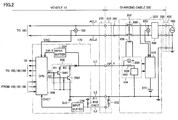
- Fig. 2 is a diagram for illustrating the charging circuit shown in Fig. 1 in greater detail.
- description of the components designated by the same reference characters as those in Fig. 1 will not be repeated.
- CCID 330 further includes an electromagnetic coil 606, a leakage detector 608, a CCID control unit 610, a battery 615, a voltage sensor 650, and a current sensor 660.
- control pilot circuit 334 includes an oscillation device 602, a resistance R20 and a voltage sensor 604.
- CCID control unit 610 includes a CPU, a storage device and an input/output buffer, and inputs/outputs the signals of each sensor and control pilot circuit 334 while controlling the charging operation of charging cable 300.
- CCID control unit 610 is supplied with a power supply from battery 615 incorporated in CCID 330.
- oscillation device 602 When the potential of pilot signal CPLT detected by voltage sensor 604 is a prescribed potential (for example, 12V), oscillation device 602 outputs a non-oscillating signal. When the potential of pilot signal CPLT is decreased from the prescribed potential as mentioned above (for example, 9V), oscillation device 602 is controlled by CCID control unit 610, to output the signal oscillating at a prescribed frequency (for example, 1 kHz) and in a prescribed duty cycle.
- a prescribed potential for example, 12V
- oscillation device 602 When the potential of pilot signal CPLT is decreased from the prescribed potential as mentioned above (for example, 9V), oscillation device 602 is controlled by CCID control unit 610, to output the signal oscillating at a prescribed frequency (for example, 1 kHz) and in a prescribed duty cycle.
- pilot signal CPLT is controlled by vehicle ECU 170, as will be described later with reference to Fig. 3 .
- the duty cycle is set based on the rated current that can be supplied from external power supply 402 through charging cable 300 to vehicle 10.
- pilot signal CPLT oscillates in a prescribed cycle.
- the pulse width of pilot signal CPLT is set. In other words, by the duty shown by the ratio of the pulse width to this oscillation cycle, vehicle ECU 170 of vehicle 10 is notified of the rated current by pilot signal CPLT from control pilot circuit 334.
- the rated current is set for each charging cable, the rated current differs according to the types of charging cable 300. Therefore, the duty of pilot signal CPLT also differs according to the types of charging cable 300.
- vehicle ECU 170 Based on the duty of pilot signal CPLT received through a control pilot line L1, vehicle ECU 170 can detect the rated current that can be supplied to vehicle 10 through charging cable 300.
- control pilot circuit 334 supplies a current to electromagnetic coil 606.
- electromagnetic coil 606 When receiving a current from control pilot circuit 334, electromagnetic coil 606 generates an electromagnetic force and closes the contact of CCID relay 332 to bring about a conducting state.
- Leakage detector 608 is provided in the middle of power line 341 of charging cable 300 within CCID 330, and detects whether leakage occurs or not. Specifically, leakage detector 608 detects the equilibrium state of the current flowing through a pair of power lines 341 in the directions opposite to each other. Then, when the equilibrium state is disturbed, leakage detector 608 detects occurrence of leakage. Although not particularly shown, when leakage detector 608 detects leakage, power feeding to electromagnetic coil 606 is cut off and the contact of CCID relay 332 is opened to bring about a non-conducting state.
- voltage sensor 650 detects the power supply voltage transmitted from external power supply 402, and notifies CCID control unit 610 of the detection value. Furthermore, current sensor 660 detects the charging current flowing through power line 341, and notifies CCID control unit 610 of the detection value.
- Connection detecting circuit 312 included within connector 310 is, for example, a limit switch as described above, in which case the contact is closed in the state where connector 310 is connected to inlet 270 while the contact is opened in the state where connector 310 is disconnected from inlet 270.
- connection signal line L3 is short-circuited to a ground line L2, with the result that the potential on connection signal line L3 becomes a ground potential (0V).
- connection detecting circuit 312 can also be a resistor (not shown). In this case, in the state where connector 310 is connected to inlet 270, a voltage signal determined by the voltage on power supply node 511 and pull-up resistance R10 and also by this resistor is generated on connection signal line L3.
- connection detecting circuit 312 is a limit switch or a resistor as described above, the potential generated on connection signal line L3 (that is, the potential of connection signal CNCT) varies between the time when connector 310 is connected to inlet 270 and the time when connector 310 is disconnected from inlet 270. Therefore, vehicle ECU 170 can detect the connection state of connector 310 by detecting the potential of connection signal line L3.
- vehicle ECU 170 in addition to power supply node 511 and pull-up resistance R10 described above, vehicle ECU 170 further includes a resistance circuit 502, input buffers 504, 506, and a CPU 508.
- Resistance circuit 502 includes pull-down resistances R1, R2, and switches SW1 and SW2.
- Pull-down resistance R1 and switch SW1 are connected in series between a vehicle ground 512 and control pilot line L1 through which pilot signal CPLT is communicated.
- Pull-down resistance R2 and switch SW2 are also connected in series between control pilot line L1 and vehicle ground 512.
- Switches SW1 and SW2 are controlled in accordance with control signals S1 and S2, respectively, from CPU 508 to be brought into a conducting state or a non-conducting state.
- This resistance circuit 502 serves to control the potential of pilot signal CPLT from the vehicle 10 side.
- Input buffer 504 receives pilot signal CPLT on control pilot line L1, and outputs the received pilot signal CPLT to CPU 508.
- Input buffer 506 receives connection signal CNCT through connection signal line L3 connected to connection detecting circuit 312 of connector 310, and outputs the received connection signal CNCT to CPU 508.
- vehicle ECU 170 applies a voltage to connection signal line L3, and the potential of connection signal CNCT is changed by connection of connector 310 to inlet 270.
- CPU 508 detects the potential of this connection signal CNCT, thereby detecting the connection state of connector 310.
- CPU 508 receives pilot signal CPLT and connection signal CNCT from input buffers 504 and 506, respectively.
- CPU 508 detects the potential of connection signal CNCT, and detects the connection state of connector 310.
- CPU 508 detects the oscillation state and the duty cycle of pilot signal CPLT, thereby detecting the rated current of charging cable 300 as described above.
- CPU 508 controls control signals S1 and S2 of switches SW1 and SW2, respectively, thereby controlling the potential of pilot signal CPLT. Consequently, CPU 508 can remotely operate CCID relay 332. Then, electric power is transmitted from external power supply 402 to vehicle 10 through charging cable 300.
- CPU 508 when the contact of CCID relay 332 is closed, the AC power from external power supply 402 is supplied to power conversion device 160, and then, the preparation for charging power storage device 150 from external power supply 402 is completed.
- CPU 508 outputs a control signal PWE to power conversion device 160, thereby converting the AC power from external power supply 402 into a DC power that can be supplied to power storage device 150. Then, CPU 508 outputs control signal SE and closes the contact of relay 155, thereby charging power storage device 150.
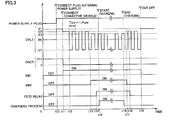
- Fig. 3 is a time chart for illustrating charging control in the charging system in Fig. 2 .
- the horizontal axis shows time while the vertical axis shows the state of connection of plug 320 to external power supply 402, the potential of pilot signal CPLT, the potential of connection signal CNCT, the states of switches SW1 and SW2, the state of CCID relay 332, and the execution state of the charging process.
- charging cable 300 is not connected to vehicle 10 and external power supply 402 until time t10.
- switches SW1, SW2 and CCID relay 332 are in an OFF state while the potential of pilot signal CPLT is 0V.
- the potential of connection signal CNCT is V11 (> 0V).
- control pilot circuit 334 generates pilot signal CPLT.
- connector 310 of charging cable 300 is not connected to inlet 270 at this time t10.
- the potential of pilot signal CPLT is V1 (for example, 12V) while pilot signal CPLT is in a non-oscillation state.
- connection signal CNCT detects that the potential of connection signal CNCT has been decreased, thereby detecting connection between connector 310 and inlet 270.
- control signal S1 is activated by CPU 508, and switch SW1 is turned on.
- the potential of pilot signal CPLT is decreased to V2 (for example, 9V) by pull-down resistance R1 of resistance circuit 502.
- CPU 508 When detecting that pilot signal CPLT has been oscillated, CPU 508 detects the rated current of charging cable 300 by the duty of pilot signal CPLT as described above.
- CPU 508 activates control signal S2 to turn on switch SW2.
- the potential of pilot signal CPLT is decreased to V3 (for example, 6V) by pull-down resistance R2 (time t13 in Fig. 3 ).
- CCID control unit 610 detects that the potential of this pilot signal CPLT has been decreased to V3
- the contact of CCID relay 332 is closed at time t14, to transmit the electric power from external power supply 402 to vehicle 10 through charging cable 300.
- CPU 508 When charging of power storage device 150 proceeds and it is determined that power storage device 150 is fully charged, CPU 508 ends the charging process (time t16 in Fig. 3 ). Then, CPU 508 deactivates control signal S2, to bring switch SW2 into a non-conducting state (time t17 in Fig. 3 ). Consequently, the potential of pilot signal CPLT becomes V2, and accordingly, the charging process is stopped while CCID relay 332 is brought into a non-conducting state (time t18), thereby ending the charging operation. Then, CPU 508 deactivates control signal S1 to bring switch SW1 into a non-conducting state, thereby shutting down the system.
- a vehicle which is regarded as a power supply source
- electrical devices and power networks external to the vehicle are supplied to electrical devices and power networks external to the vehicle.
- a vehicle may be used as a power supply for using an electrical device when working outdoors, in camping or the like.
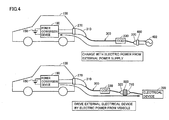
- a conversion adapter 800 is provided as shown in the lower section in Fig. 4 .
- plug 320 of charging cable 300 used during external charging and a power supply plug 710 of an electrical device 700 external to the vehicle can be connected.
- this conversion adapter 800 allows the electric power from vehicle 10 to be supplied to electrical device 700 external to the vehicle through charging cable 300 (which will be hereinafter referred to as "power feeding to outside").
- power conversion device 160 of vehicle 10 converts the DC power stored in power storage device 150 serving as a power generation device into AC power that can be used in electrical device 700 (for example, AC 100V, 200V and the like), and the converted power is supplied to electrical device 700.
- engine 140 and MG 120 are included as a power generation device of vehicle 10, in addition to the above-described power storage device 150.
- the electric power (AC power) generated by engine 140 driving MG 120 is converted by motor drive device 180 and power conversion device 160 into AC power that can be used in electrical device 700. Then, the converted power can be supplied to electrical device 700.
- AC power AC power
- vehicle 10 is a fuel-cell vehicle, it is also possible to supply the electric power generated by a fuel cell.
- power conversion device 160 used in the present embodiment should have a function of converting the electric power stored in vehicle 10 and/or the electric power generated in vehicle 10 into driving electric power for external electrical device 700.
- one power conversion device capable of bidirectionally converting electric power between external charging and power feeding to outside may be provided, or a power conversion device exclusively for external charging and a power conversion device exclusively for power feeding to outside may be separately provided.
- adapter 800 when adapter 800 is removed from plug 320 of charging cable 300 in the hot-line state during power feeding to outside using such adapter 800, an arc current may be generated between terminals, or a voltage may be kept applied to the terminal portion exposed on the plug 320 side until completion of the operation of ending the power-feeding operation on the vehicle side. This may cause a short circuit or a ground fault between the terminal portions, thereby causing an excessive current to flow therethrough, which may lead to deterioration or failures of devices or may exert an influence upon surroundings.
- adapter 800 proposed in the present embodiment is provided with a leakage generation circuit that artificially causes a leakage state by electrical connection between the power transmission path used for power feeding and the ground when adapter 800 is removed from plug 320.
- Charging cable 300 and/or vehicle 10 generally include(s) a leakage detection circuit and a power cut-off circuit for preventing an accident and a failure. Therefore, power feeding from vehicle 10 can be immediately stopped by artificially causing the leakage state as described above.
- Figs. 5 and 6 each are a schematic diagram showing an example of adapter 800 used during power feeding to outside, as described with reference to Fig. 4 .
- adapter 800 includes a connection unit 801 for connecting plug 320 of charging cable 300, a connection unit 805 for connecting power supply plug 710 of external electrical device 700, an operation unit 807, and a locking unit 808.
- Connection unit 801 on the charging cable 300 side is provided with a terminal unit 802 to which the terminal of plug 320 is connected.
- Connection unit 801 is also provided with an insertion hole 803 through which an operation member 322 formed in a protruding shape as shown in Fig. 6 and provided in plug 320 can be inserted when adapter 800 and plug 320 are connected to each other. The function of operation member 322 will be described later.
- locking unit 808 engages with a concave portion 321 provided in plug 320.
- locking unit 808 and concave portion 321 engage with each other, so that easy disconnection of adapter 800 from plug 320 can be prevented.
- Locking unit 808, which cooperatively operates with operation unit 807 (for example, a push button) included in adapter 800, is operated in the direction indicated by an arrow in Fig. 5 or 6 when operation unit 807 is operated. This allows disengagement between locking unit 808 and concave portion 321.
- operation unit 807 for example, a push button
- locking unit 808 and operation unit 807 are not an indispensable configuration in the present invention, such a configuration is suitable since it can prevent adapter 800 from being unintentionally pulled out from plug 320.
- connection unit 805 on the electrical device 700 side is provided with a terminal unit 806 corresponding to the terminal shape of power supply plug 710 of electrical device 700.
- Terminal unit 806 has a shape that is, for example, adapted to a voltage (100V, 200V and the like) to be used and the standards specified in the country in which this terminal unit is to be used.
- connection units 801 and 805 are housed in the same housing as an integrated structure, which may be however also configured such that the connector on the charging cable side and the connector on the electrical device side are separated from each other and coupled through a cable serving as a power transmission medium, though not shown in the figure.
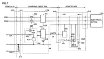
- Fig. 7 is a detailed diagram of a circuit in the case where adapter 800 according to the first embodiment is used for power feeding.
- the configuration of vehicle 10 is the same as that in Fig. 2 , and components in vehicle 10 and charging cable 300 are partially not shown in Fig. 7 .
- the same components as those in Fig. 2 will not be explained in Fig. 7 .
- adapter 800 includes a signal generation unit 850 and a leakage generation circuit 860 in addition to connection units 801 and 805.
- signal generation unit 850 When adapter 800 is connected to plug 320 of charging cable 300, signal generation unit 850 is electrically connected to a signal line L4 within charging cable 300 through another terminal unit that is not shown in Fig. 6 .
- signal generation unit 850 supplies a signal CNCT2 to CCID control unit 610 through signal line L4 that indicates connection between adapter 800 and plug 320.
- Signal generation unit 850 may be a control device having a CPU or may be a control circuit exhibiting a desired function. When signal generation unit 850 requires a power supply voltage for driving, the power supply voltage is supplied from the battery (not shown) incorporated in adapter 800.
- CCID control unit 610 determines whether or not charging cable 300 and adapter 800 are connected to each other. When determining that charging cable 300 and adapter 800 are connected to each other, CCID control unit 610 outputs pilot signal CPLT to vehicle ECU 170 using a frequency and/or a potential different from those during external charging. Consequently, CCID control unit 610 can cause vehicle ECU 170 to perform a power feeding operation.
- Leakage generation circuit 860 includes a switch SW10 serving as a switching unit and a resistance R30.
- Switch SW10 serves as a switch, for example, having two contacts CN1 and CN2. One of contacts CN1 and CN2 is closed as switch SW10 is operated.
- Contact CN1 has one end connected to a power transmission path leading to power line ACL1 within adapter 800 and the other end connected to a ground line.
- the power transmission path leading to power line ACL1 and the ground line are connected through resistance R30. Accordingly, when contact CN1 is closed while a current flows through this power transmission path, a leakage state is to occur.
- both ends of contact CN2 are connected to the ground line.
- switch SW10 In the state where adapter 800 is not connected to plug 320 or the state where adapter 800 and plug 320 are not completely fitted to each other, switch SW10 is brought into the state where contact CN1 is closed and contact CN2 is opened. Then, when plug 320 is completely fitted to adapter 800, switch SW10 is operated by operation member 322 provided in plug 320, so that contact CN1 is opened and contact CN2 is closed.
- leakage generation circuit 860 since contact CN1 is opened in the state where adapter 800 and plug 320 are completely fitted to each other, a leakage state does not occur even if vehicle 10 supplies electric power to electrical device 700.
- a leakage state is brought about by closing contact CN1.
- the leakage state is detected by leakage detector 608 included in CCID 330 described above.
- CCID control unit 610 opens CCID relay 332, thereby cutting off the electric power to electrical device 700.
- switch SW10 is not limited to such a configuration having two contacts as shown in Fig. 7 as long as it is configured to switch between connection and disconnection between the power transmission path within adapter 800 and the ground.
- switch SW10 may be configured to have one contact without having contact CN2 in Fig. 7 .
- Figs. 8 and 9 each are a time chart for illustrating control during power feeding in the first embodiment.
- Fig. 8 is a time chart in the normal case where an adapter is not removed during power feeding to outside
- Fig. 9 is a time chart in the case where an adapter is removed during power feeding to outside.
- the horizontal axis shows time while the vertical axis shows the connection state of adapter 800, a potential of pilot signal CPLT, a potential of connection signal CNCT, the state of a connection signal CNCT2, the states of switches SW1 and SW2, the state of CCID relay 332, the state of executing the power feeding process, and the state of leakage detection signal LKG from leakage detector 608.
- pilot signal CPLT is V1 (for example, 12V) and pilot signal CPLT is in a non-oscillation state.
- CPU 508 detects that the potential of connection signal CNCT is decreased, thereby detecting that charging cable 300 is connected to inlet 270.
- CPU 508 activates control signal S1 to thereby turn on switch SW1 (time t21).
- the potential of pilot signal CPLT is decreased to V2 (for example, 9V) by pull-down resistance R1 of resistance circuit 502.
- connection signal CNCT2 is brought into the ON state by signal generation unit 850 of adapter 800.
- CCID control unit 610 recognizes that plug 320 of charging cable 300 has been connected to adapter 800.
- CCID control unit 610 closes CCID relay 332.
- CPU 508 detects that pilot signal CPLT has been oscillated. However, as described above, since an oscillation frequency Fsup of pilot signal CPLT output from CCID 330 during the power feeding operation is lower than an oscillation frequency Fchr during the charging operation, CPU 508 recognizes based on this difference between the oscillation frequencies that adapter 800 has been connected to charging cable 300 and that the power feeding operation has been instructed.
- CPU 508 closes the contact of relay 155 while controlling power conversion device 160 ( Fig. 1 ), thereby starting to supply electric power from power storage device 150 ( Fig. 1 ) (time t23).
- adapter 800 is removed by the user during power feeding from power storage device 150 to electrical device 700.
- a leakage state is brought about by leakage generation circuit 860 in adapter 800.
- leakage detector 608 within CCID 330 detects this leakage state, and leakage detection signal LKG is set to be ON.
- CCID control unit 610 opens CCID relay 332 to cut-off the electric power to adapter 800 (time t35).
- connection signal CNCT2 is turned OFF by removing adapter 800, CCID control unit 610 stops oscillation of pilot signal CPLT. Consequently, the charging process of vehicle ECU 170 is stopped (time t36).
- the electric power to the plug of the charging cable can be immediately cut off by the time when the power feeding process of the vehicle is stopped.
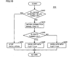
- Fig. 10 is a flowchart for illustrating a control process for oscillating pilot signal CPLT that is performed in CCID control unit 610 in the first embodiment.
- the process is implemented by executing the program stored in CCID control unit 610 in advance in predetermined cycles.
- the process may also be implemented for a part of the steps by constructing dedicated hardware (electronic circuit).
- CCID control unit 610 determines whether or not the leakage state is detected by leakage detector 608, that is, whether or not leakage detection signal LKG is turned ON.
- CCID control unit 610 obtains connection signal CNCT2. Then in S320, CCID control unit 610 determines whether or not connection signal CNCT2 is ON, that is, whether or not charging cable 300 and adapter 800 are connected to each other.
- CCID control unit 610 When connection signal CNCT2 is OFF (NO in S320), CCID control unit 610 recognizes that adapter 800 is not connected to charging cable 300 and the normal external charging mode is employed. Then, in S340, CCID control unit 610 sets an oscillation frequency Fcplt of pilot signal CPLT at frequency Fchr for performing external charging, and causes pilot signal CPLT to oscillate.
- CCID control unit 610 recognizes that adapter 800 is connected to charging cable 300 and the mode for power feeding to outside is employed. Then, in S330, CCID control unit 610 sets oscillation frequency Fcplt of pilot signal CPLT at frequency Fsup lower than frequency Fchr during external charging (Fsup ⁇ Fchr), and causes pilot signal CPLT to oscillate.
- CCID control unit 610 stops oscillation of pilot signal CPLT. Thereby, CCID control unit 610 stops the power feeding operation of vehicle ECU 170.
- Fig. 11 is a flowchart for illustrating a control process for switching between the charging process and the power feeding process that are performed in vehicle ECU 170 in the first embodiment.
- the process is implemented by executing the program stored in CPU 508 of vehicle ECU 170 in advance in predetermined cycles.
- the process may also be implemented for a part of the steps by constructing dedicated hardware (electronic circuit).
- CPU 508 determines in S100 whether or not pilot signal CPLT is oscillating.
- pilot signal CPLT is oscillating (YES in S100)
- CPU 508 recognizes that charging cable 300 is connected to inlet 270, and in S110, obtains oscillation frequency Fcplt of pilot signal CPLT.
- CPU 508 determines in S120 whether or not the obtained oscillation frequency Fcplt is equal to oscillation frequency Fchr in the case of the charging operation. It is to be noted that, in determination performed in S120, the obtained oscillation frequency Fcplt does not need to be completely equal to oscillation frequency Fchr during the charging operation, and the difference between oscillation frequency Fcplt and oscillation frequency Fchr only needs to fall within a prescribed range (
- oscillation frequency Fcplt is not equal to oscillation frequency Fchr (NO in S120)
- the process proceeds to S 140, in which CPU 508 determines whether or not the obtained oscillation frequency Fcplt is equal to oscillation frequency Fsup during the power feeding operation. Also in this case, similarly to the case of determination in S120, the obtained oscillation frequency Fcplt does not need to be completely equal to oscillation frequency Fsup during the power feeding operation, and the difference between oscillation frequency Fcplt and oscillation frequency Fsup only needs to fall within a prescribed range (
- the electric power can be supplied, using a conversion adaptor for a charging cable, from the vehicle to the electrical device external to the vehicle through the charging cable. Furthermore, when the adapter is removed during power feeding to outside, this power feeding can be immediately stopped by the operation of the leakage generation circuit provided in the adapter. This can prevent the exposed terminal unit of the plug of the charging cable from being kept applied with a voltage, so that it becomes possible to suppress deterioration and failures of devices and influences upon the surroundings.
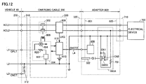
- leakage generation circuit 860 explained with reference to Fig. 7 in the above is configured to cause a leakage state by electrical connection between the power transmission path leading to power line ACL1 of the vehicle and the ground, the manner of causing a leakage state is not limited thereto.
- the other power transmission path that is, a power transmission path leading to power line ACL2 of the vehicle, may be electrically connected to the ground through a resistance R31.
- both of the power transmission paths may be electrically connected to the ground.
- the operation of switch SW10 of the leakage generation circuit may be performed cooperatively with the operation of operation unit 807 for operating locking unit 808 of adapter 800, as with leakage generation circuit 860C shown in Fig. 14 .
- operation unit 807 is operated to close contact CN2 of switch SW10, thereby bringing about a leakage state.
- leakage detection can be performed also on the vehicle side.
- Fig. 15 is a detailed diagram of a circuit in the case where power feeding is performed through a charging cable using an adapter in the second embodiment.
- a leakage detector 190 is provided in vehicle 10.
- Fig. 15 does not show a leakage detector 608 within CCID 330 of charging cable 300 unlike in Fig. 7 , but a leakage detector may be provided also within CCID 330 like in Fig. 7 .
- leakage detector 190 detects whether or not a leakage state occurs in power lines ACL1 and ACL2.
- vehicle ECU 170 stops the power feeding operation of power conversion device 160 and also controls the potential of pilot signal CPLT using resistance circuit 502, so as to open CCID relay 332 of charging cable 300.
- vehicle ECU 170 opens relay 155 in vehicle 10 to cut off the electric power supplied from power storage device 150 to power conversion device 160.
- a relay (not shown) used only for cutting off the electric power during leakage may be additionally provided between power conversion device 160 and inlet 270, and this relay may be opened to thereby cut off the electric power.
- some charging cables may not have a control device such as a CCID.
- Fig. 16 is a detailed diagram of a circuit in the case where a charging cable 300A not having a CCID is used. Referring to Fig. 16 , since charging cable 300A does not have a CCID, it is not possible to determine by a CCID whether or not the adapter and the charging cable are connected, and to use a pilot signal CPLT to cause the vehicle to execute the power feeding operation, which is as described in the first embodiment.
- the signal indicating connection from signal generation unit 850 of adapter 800 is directly transmitted to CPU 508 of vehicle ECU 170 using a signal line L5 included in charging cable 300A, to cause vehicle ECU 170 to recognize connection between adapter 800 and charging cable 300A.
- the control device on the vehicle side is used to detect connection between the adapter and the charging cable and also detect whether or not a leakage state occurs, and thereby, power feeding to outside can be implemented through the charging cable using the adapter, and also power feeding can be immediately stopped in response to removal of the adapter during power feeding to outside.
Landscapes
- Engineering & Computer Science (AREA)
- Power Engineering (AREA)
- Transportation (AREA)
- Mechanical Engineering (AREA)
- Life Sciences & Earth Sciences (AREA)
- Sustainable Development (AREA)
- Sustainable Energy (AREA)
- Electric Propulsion And Braking For Vehicles (AREA)
- Charge And Discharge Circuits For Batteries Or The Like (AREA)
Abstract
Description
- The present invention relates to an adapter, and a vehicle for performing power feeding using the adapter, and more specifically to a technique for supplying electric power generated by a vehicle to an external electrical device.
- In recent years, a vehicle equipped with a power storage device (for example, a secondary battery, a capacitor and the like) and running with driving force generated from the electric power stored in the power storage device has received attention as an environmentally-friendly vehicle. Such a vehicle includes, for example, an electric vehicle, a hybrid vehicle, a fuel-cell vehicle, and the like. There is a proposed technique for charging the power storage device mounted in the above-described vehicle by a commercial power supply having high power generation efficiency.
- As a hybrid vehicle, there is also a known vehicle equipped with a power storage device that can be charged by a power supply external to the vehicle (hereinafter simply referred to as an "external power supply") as in the case of the electric vehicle (which will be hereinafter simply referred to as "external charging"). For example, the so-called "plug-in hybrid vehicle" is known which is provided with a power storage device that can be charged by a household power supply through the charging cable connecting between the receptacle provided in the house and the charging port provided in the vehicle. According to this, an improvement in the fuel consumption efficiency of the hybrid vehicle can be expected.
- As for such an externally chargeable vehicle, there has been developed a concept of supplying electric power from a vehicle, which is regarded as a power supply source, to a commonly-used electrical device external to the vehicle, as seen in the smart grid and the like. Furthermore, a vehicle may be used as a power supply for using an electrical device when working outdoors, in camping or the like.
- Japanese Patent Laying-Open No.
2010-035277 -
- PTD 1: Japanese Patent Laying-Open No.
2010-035277 - PTD 2: Japanese Patent Laying-Open No.
2010-165619 - In the system disclosed in Japanese Patent Laying-Open No.
2010-035277 - In this case, if the plug of the cable is removed during the power feeding operation, the terminal portion of the plug may be kept applied with a power-feeding voltage, which may cause a failure or deterioration of devices or may exert influences upon surrounding devices. Accordingly, it is desirable to immediately stop the power feeding operation when the plug of the cable is pulled out.
- The present invention has been made to solve the above-described problems. An object of the present invention is to provide, for an externally chargeable vehicle, a conversion adaptor that allows electric power to be supplied to an external electrical device from the vehicle using a charging power cable and also allows the power feeding operation to be stopped appropriately when the charging power cable is removed.
- An adapter according to the present invention serves as an adapter used for supplying electric power from a power source including a power storage device mounted in a vehicle to an electrical device external to the vehicle through a charging cable. The vehicle is capable of performing external charging that allows the power storage device to be charged using electric power supplied from an external power supply through the charging cable. In response to a signal instructing power feeding that is generated by connection between the adapter and the charging cable, the vehicle performs power feeding to the electrical device. The adapter includes a first connection unit capable of connecting a power supply plug connected to the external power supply in the charging cable during external charging, a second connection unit electrically connected to the first connection unit and capable of connecting a power supply plug of the electrical device, and a leakage generation circuit causing a leakage state in a power transmission path connecting the first connection unit and the second connection unit when the adapter and the charging cable are incompletely fitted to each other.
- Preferably, the leakage generation circuit is configured to cause the leakage state by electrical connection between at least one power transmission path of the power transmission paths and a ground when the adapter and the charging cable are incompletely fitted to each other.
- Preferably, the leakage generation circuit includes a switching unit configured to switch between connection and disconnection between the power transmission path and the ground. The switching unit causes all of the power transmission paths to be disconnected from the ground when the adapter and the charging cable are completely fitted to each other, and causes at least one power transmission path to be electrically connected to the ground when the adapter and the charging cable are incompletely fitted to each other.
- Preferably, the switching unit is operated by an operation member provided in a power supply plug of the charging cable when the adapter and the charging cable are connected to each other.
- Preferably, the adapter further includes a locking unit configured to engage with a power supply plug of the charging cable when the adapter and the charging cable are completely fitted to each other, and an operation unit configured to operate the locking unit for releasing the engagement between the power supply plug and the adapter. The switching unit causes at least one power transmission path to be electrically connected to the ground in accordance with an operation of the operation unit by a user.
- Preferably, the charging cable includes a leakage detection circuit for detecting the leakage state. The charging cable stops outputting the signal instructing power feeding to the vehicle when the leakage state is detected.
- Preferably, the charging cable further includes a cut-off circuit for cutting off power feeding to the adapter when the leakage state is detected.
- Preferably, the vehicle includes a leakage detection circuit for detecting the leakage state. The vehicle stops power feeding to the charging cable when the leakage state is detected.
- A vehicle according to the present invention serves as a vehicle that is capable of performing external charging that allows a power storage device mounted therein to be charged using electric power supplied from an external power supply through a charging cable and is capable of feeding electric power to an external electrical device by connection of an adapter to the charging cable. The vehicle includes a power source including the power storage device; an inlet for connecting the charging cable during external charging; a power conversion device for converting electric power from the power source to supply the converted electric power to the inlet; and a control device for controlling the power conversion device. The adapter includes a first connection unit capable of connecting a power supply plug connected to the external power supply in the charging cable during external charging, a second connection unit electrically connected to the first connection unit and capable of connecting a power supply plug of the electrical device, and a leakage generation circuit causing a leakage state to occur in a power transmission path connecting the first connection unit and the second connection unit when the adapter and the charging cable are incompletely fitted to each other. In response to reception of a signal instructing power feeding that is generated by connection between the adapter and the charging cable, the control device drives the power conversion device to supply the electric power from the power source to the electrical device. Then, the control device stops power feeding to the electrical device when the leakage state is detected.
- By using a conversion adaptor according to the present invention, in an externally chargeable vehicle, it becomes possible to supply electric power from the vehicle to an external electrical device through a charging power cable and also possible to appropriately stop a power feeding operation when the adapter is removed from the charging power cable during power feeding from the vehicle.
-
-
Fig. 1 is an entire block diagram of a charging system in a vehicle according to the present embodiment. -
Fig. 2 is an example of a detailed diagram of a charging mechanism inFig. 1 . -
Fig. 3 is a time chart for illustrating charging control in the case where external charging is performed. -
Fig. 4 is a schematic diagram for illustrating the outline of the present embodiment. -
Fig. 5 is a diagram showing the outline of an adapter according to the present embodiment. -
Fig. 6 is a diagram for illustrating the adapter inFig. 5 . -
Fig. 7 is a detailed diagram of a circuit in the case where power feeding is performed through a charging cable by using the adapter in the first embodiment. -
Fig. 8 is a time chart for illustrating control during power feeding in the first embodiment. -
Fig. 9 is a time chart for illustrating control when the adapter is removed during power feeding in the first embodiment. -
Fig. 10 is a flowchart for illustrating a control process for oscillating a pilot signal that is performed in a CCID control unit in the first embodiment. -
Fig. 11 is a flowchart for illustrating a control process for switching between a charging process and a power feeding process that are performed in a vehicle ECU in the first embodiment. -
Fig. 12 is a diagram for illustrating the first example of a leakage generation circuit. -
Fig. 13 is a diagram for illustrating the second example of a leakage generation circuit. -
Fig. 14 is a diagram for illustrating the third example of a leakage generation circuit. -
Fig. 15 is a detailed diagram of a circuit in the second embodiment. -
Fig. 16 is a detailed diagram of a circuit in the third embodiment. - The embodiments of the present invention will be hereinafter described in detail with reference to the accompanying drawings, in which the same or corresponding components are designated by the same reference characters, and description thereof will not be repeated.
-
Fig. 1 is a schematic diagram of a charging system in avehicle 10 according to the first embodiment. Explained with reference toFig. 1 will be the case where the electric power from anexternal power supply 402 is used to charge apower storage device 150 mounted invehicle 10. - It is to be noted that the configuration of
vehicle 10 is not particularly limited as long as it can run with electric power from the power storage device that can be charged by an external power supply.Vehicle 10 may be, for example, a hybrid vehicle, an electric vehicle, a fuel-cell vehicle, and the like. Also, the configuration ofvehicle 10 is applicable to any vehicle that, for example, runs with an internal combustion engine as long as it is provided with a chargeable power storage device. - Referring to
Fig. 1 ,vehicle 10 includes aninlet 270, apower conversion device 160, arelay 155, apower storage device 150, adrive unit 20, a vehicle ECU (Electronic Control Unit) 170, and avoltage sensor 182.Drive unit 20 includes amotor drive device 180, a motor generator (which will be hereinafter also referred to as an "MG") 120, adriving wheel 130, anengine 140, and apower split device 145. - A
connector 310 provided in a chargingcable 300 is connected toinlet 270. -
Power conversion device 160 is connected toinlet 270 through power lines ACL1 and ACL2. Furthermore,power conversion device 160 is connected topower storage device 150 throughrelay 155. Based on a control signal PWE fromvehicle ECU 170,power conversion device 160 converts alternating-current (AC) power supplied from apower supply 402 external to the vehicle into a direct-current (DC) power with whichpower storage device 150 can be charged. Then,power conversion device 160 supplies the converted DC power topower storage device 150. -
Power storage device 150 is a chargeable and dischargeable electric power storage component.Power storage device 150 is configured to include, for example, a secondary battery such as a lithium-ion battery, a nickel-metal hydride battery or a lead acid battery, or a power storage element such as an electric double layer capacitor. -
Power storage device 150 stores the DC power supplied frompower conversion device 160.Power storage device 150 is connected tomotor drive device 180 drivingMG 120, and supplies the DC power used for generating a driving force used for vehicle running. Furthermore,power storage device 150 stores the electric power generated byMG 120. - Although not shown,
power storage device 150 further includes a voltage sensor for detecting a voltage ofpower storage device 150 and a current sensor for detecting a current that is input to and output frompower storage device 150.Power storage device 150 outputs the detection values of the voltage and the current detected by these sensors tovehicle ECU 170. -
Motor drive device 180 is connected topower storage device 150 andMG 120.Motor drive device 180 is controlled byvehicle ECU 170, to convert the electric power supplied frompower storage device 150 into electric power for drivingMG 120.Motor drive device 180 is configured, for example, to include a three-phase inverter. -
MG 120 is connected tomotor drive device 180 and also connected throughpower split device 145 todriving wheel 130.MG 120 receives electric power supplied frommotor drive device 180 to generate a driving force used for causingvehicle 10 to run. WhileMG 120 receives rotating force from drivingwheel 130 to generate AC power and generates regenerative braking force by a regenerative torque command fromvehicle ECU 170.MG 120 is configured to include, for example, a three-phase AC motor generator including a rotor having a permanent magnet embedded therein and a stator having a Y-connected three-phase coil. -
MG 120 is connected also toengine 140 throughpower split device 145.Vehicle ECU 170 controls the driving forces of the engine andMG 120 to be set at an optimal ratio. Furthermore, when being driven byengine 140,MG 120 can also operate as a power generator. The electric power generated byMG 120 is stored inpower storage device 150. Alternatively, the electric power generated byMG 120 may be supplied to electrical devices external to the vehicle throughinlet 270 as described below. -
Voltage sensor 182 is connected between power lines ACL1 and ACL2, and detects a voltage of the electric power supplied fromexternal power supply 402. Then,voltage sensor 182 outputs a detection value VAC of the voltage tovehicle ECU 170. -
Relay 155 is interposed in the path connectingpower conversion device 160 andpower storage device 150.Relay 155 is controlled by a control signal SE fromvehicle ECU 170 to switch between supply and cut-off of the electric power betweenpower conversion device 160 andpower storage device 150. In addition, although the present embodiment shows the configuration in which relay 155 is separately provided,relay 155 may also be included inpower storage device 150 orpower conversion device 160. - Although not shown in
Fig. 1 ,vehicle ECU 170 includes a CPU (Central Processing Unit), a storage device and an input/output buffer.Vehicle ECU 170 inputs the signal from each sensor and the like and outputs the control command to each device, and also controlsvehicle 10 and each device. The control of these devices and the like is not limited to the process by means of software, but the process can be implemented by constructing dedicated hardware (an electronic circuit). -
Vehicle ECU 170 receives a connection signal CNCT and a pilot signal CPLT from chargingcable 300 throughinlet 270. Furthermore,vehicle ECU 170 receives a voltage detection value VAC of the received electric power fromvoltage sensor 182. -
Vehicle ECU 170 receives inputs of detection values about a current, a voltage and a temperature from the sensor (not shown) installed withinpower storage device 150, to calculate the state amount showing the state of charge of power storage device 150 (which will be hereinafter also referred to as an "SOC (State of Charge)"). - Then, based on these pieces of information,
vehicle ECU 170 controlspower conversion device 160,relay 155 and the like for chargingpower storage device 150. - Charging
cable 300 has aconnector 310 provided at its end on the vehicle side; aplug 320 provided at its end on the external power supply side; a charging circuit interrupt device (which will be hereinafter also referred to as a "CCID") 330; and apower line unit 340 that connects between the devices and inputs/outputs electric power and a control signal. -
Power line unit 340 includes apower line unit 340A connecting betweenplug 320 andCCID 330, and apower line unit 340B connecting betweenconnector 310 andCCID 330. Furthermore,power line unit 340 includes apower line 341 for transmitting electric power fromexternal power supply 402. - Charging
cable 300 is connected to areceptacle 400 of external power supply 402 (for example, a commercial power supply) throughplug 320 of chargingcable 300. Furthermore,inlet 270 provided in the body ofvehicle 10 andconnector 310 of chargingcable 300 are connected to each other for transmitting the electric power tovehicle 10 frompower supply 402 external to the vehicle. Chargingcable 300 is detachable from and attachable toexternal power supply 402 andvehicle 10. - A
connection detecting circuit 312 detecting connection ofconnector 310 is provided withinconnector 310 and detects the state of connection betweeninlet 270 andconnector 310.Connection detecting circuit 312 outputs a connection signal CNCT showing the connection state tovehicle ECU 170 ofvehicle 10 throughinlet 270. -
Connection detecting circuit 312 may be configured as a limit switch as shown inFig. 1 , so as to cause the potential of connection signal CNCT to be a ground potential (0V) whenconnector 310 is connected toinlet 270. Alternatively,connection detecting circuit 312 may be configured as a resistor (not shown) having a prescribed resistance value, so as to cause the potential of connection signal CNCT to be decreased to a prescribed potential at the time of connection. In each case,vehicle ECU 170 detects the potential of connection signal CNCT to thereby detect thatconnector 310 has been connected toinlet 270. -
CCID 330 includes aCCID relay 332 and acontrol pilot circuit 334.CCID relay 332 is interposed in apower line 341 within chargingcable 300.CCID relay 332 is controlled bycontrol pilot circuit 334. WhenCCID relay 332 is opened, the electric path is cut off within chargingcable 300. On the other hand, whenCCID relay 332 is closed, the electric power is supplied fromexternal power supply 402 tovehicle 10. -
Control pilot circuit 334 outputs pilot signal CPLT tovehicle ECU 170 throughconnector 310 andinlet 270. This pilot signal CPLT serves as a signal fromcontrol pilot circuit 334 for notifyingvehicle ECU 170 about the rated current of chargingcable 300. Furthermore, pilot signal CPLT also serves as a signal used for remote-controllingCCID relay 332 byvehicle ECU 170 based on the potential of pilot signal CPLT controlled byvehicle ECU 170. Also,control pilot circuit 334 controlsCCID relay 332 based on the change in the potential of pilot signal CPLT. - The above-described pilot signal CPLT and connection signal CNCT, and the configuration such as a shape and a terminal arrangement of
inlet 270,connector 310 and the like are standardized, for example, by SAE (Society of Automotive Engineers) in the U. S., Japan Electric Vehicle Association, and the like. -
Fig. 2 is a diagram for illustrating the charging circuit shown inFig. 1 in greater detail. InFig. 2 , description of the components designated by the same reference characters as those inFig. 1 will not be repeated. - Referring to
Fig. 2 , in addition toCCID relay 332 andcontrol pilot circuit 334,CCID 330 further includes anelectromagnetic coil 606, aleakage detector 608, aCCID control unit 610, abattery 615, avoltage sensor 650, and acurrent sensor 660. Furthermore,control pilot circuit 334 includes anoscillation device 602, a resistance R20 and avoltage sensor 604. - Although not shown,
CCID control unit 610 includes a CPU, a storage device and an input/output buffer, and inputs/outputs the signals of each sensor andcontrol pilot circuit 334 while controlling the charging operation of chargingcable 300.CCID control unit 610 is supplied with a power supply frombattery 615 incorporated inCCID 330. - When the potential of pilot signal CPLT detected by
voltage sensor 604 is a prescribed potential (for example, 12V),oscillation device 602 outputs a non-oscillating signal. When the potential of pilot signal CPLT is decreased from the prescribed potential as mentioned above (for example, 9V),oscillation device 602 is controlled byCCID control unit 610, to output the signal oscillating at a prescribed frequency (for example, 1 kHz) and in a prescribed duty cycle. - In addition, the potential of pilot signal CPLT is controlled by
vehicle ECU 170, as will be described later with reference toFig. 3 . Furthermore, the duty cycle is set based on the rated current that can be supplied fromexternal power supply 402 through chargingcable 300 tovehicle 10. - When the potential of pilot signal CPLT is decreased from the prescribed potential as described above, pilot signal CPLT oscillates in a prescribed cycle. In this case, based on the rated current that can be supplied to
vehicle 10 through chargingcable 300 fromexternal power supply 402, the pulse width of pilot signal CPLT is set. In other words, by the duty shown by the ratio of the pulse width to this oscillation cycle,vehicle ECU 170 ofvehicle 10 is notified of the rated current by pilot signal CPLT fromcontrol pilot circuit 334. - Since the rated current is set for each charging cable, the rated current differs according to the types of charging
cable 300. Therefore, the duty of pilot signal CPLT also differs according to the types of chargingcable 300. - Based on the duty of pilot signal CPLT received through a control pilot line L1,
vehicle ECU 170 can detect the rated current that can be supplied tovehicle 10 through chargingcable 300. - When the potential of pilot signal CPLT is further decreased by vehicle ECU 170 (for example, 6V),
control pilot circuit 334 supplies a current toelectromagnetic coil 606. When receiving a current fromcontrol pilot circuit 334,electromagnetic coil 606 generates an electromagnetic force and closes the contact ofCCID relay 332 to bring about a conducting state. -
Leakage detector 608 is provided in the middle ofpower line 341 of chargingcable 300 withinCCID 330, and detects whether leakage occurs or not. Specifically,leakage detector 608 detects the equilibrium state of the current flowing through a pair ofpower lines 341 in the directions opposite to each other. Then, when the equilibrium state is disturbed,leakage detector 608 detects occurrence of leakage. Although not particularly shown, whenleakage detector 608 detects leakage, power feeding toelectromagnetic coil 606 is cut off and the contact ofCCID relay 332 is opened to bring about a non-conducting state. - When plug 320 of charging
cable 300 is inserted intoreceptacle 400,voltage sensor 650 detects the power supply voltage transmitted fromexternal power supply 402, and notifiesCCID control unit 610 of the detection value. Furthermore,current sensor 660 detects the charging current flowing throughpower line 341, and notifiesCCID control unit 610 of the detection value. -
Connection detecting circuit 312 included withinconnector 310 is, for example, a limit switch as described above, in which case the contact is closed in the state whereconnector 310 is connected toinlet 270 while the contact is opened in the state whereconnector 310 is disconnected frominlet 270. - In the state where
connector 310 is disconnected frominlet 270, a voltage signal determined by the voltage on apower supply node 511 and a pull-up resistance R10 included invehicle ECU 170 is generated as connection signal CNCT on a connection signal line L3. Furthermore, in the state whereconnector 310 is connected toinlet 270, connection signal line L3 is short-circuited to a ground line L2, with the result that the potential on connection signal line L3 becomes a ground potential (0V). - It is to be noted that
connection detecting circuit 312 can also be a resistor (not shown). In this case, in the state whereconnector 310 is connected toinlet 270, a voltage signal determined by the voltage onpower supply node 511 and pull-up resistance R10 and also by this resistor is generated on connection signal line L3. - Even if
connection detecting circuit 312 is a limit switch or a resistor as described above, the potential generated on connection signal line L3 (that is, the potential of connection signal CNCT) varies between the time whenconnector 310 is connected toinlet 270 and the time whenconnector 310 is disconnected frominlet 270. Therefore,vehicle ECU 170 can detect the connection state ofconnector 310 by detecting the potential of connection signal line L3. - In
vehicle 10, in addition topower supply node 511 and pull-up resistance R10 described above,vehicle ECU 170 further includes aresistance circuit 502, input buffers 504, 506, and aCPU 508. -
Resistance circuit 502 includes pull-down resistances R1, R2, and switches SW1 and SW2. Pull-down resistance R1 and switch SW1 are connected in series between avehicle ground 512 and control pilot line L1 through which pilot signal CPLT is communicated. Pull-down resistance R2 and switch SW2 are also connected in series between control pilot line L1 andvehicle ground 512. Switches SW1 and SW2 are controlled in accordance with control signals S1 and S2, respectively, fromCPU 508 to be brought into a conducting state or a non-conducting state. - This
resistance circuit 502 serves to control the potential of pilot signal CPLT from thevehicle 10 side. -
Input buffer 504 receives pilot signal CPLT on control pilot line L1, and outputs the received pilot signal CPLT toCPU 508.Input buffer 506 receives connection signal CNCT through connection signal line L3 connected toconnection detecting circuit 312 ofconnector 310, and outputs the received connection signal CNCT toCPU 508. As described above,vehicle ECU 170 applies a voltage to connection signal line L3, and the potential of connection signal CNCT is changed by connection ofconnector 310 toinlet 270.CPU 508 detects the potential of this connection signal CNCT, thereby detecting the connection state ofconnector 310. -
CPU 508 receives pilot signal CPLT and connection signal CNCT frominput buffers -
CPU 508 detects the potential of connection signal CNCT, and detects the connection state ofconnector 310. - Furthermore,
CPU 508 detects the oscillation state and the duty cycle of pilot signal CPLT, thereby detecting the rated current of chargingcable 300 as described above. - Then, based on the potential of connection signal CNCT and the oscillation state of pilot signal CPLT,
CPU 508 controls control signals S1 and S2 of switches SW1 and SW2, respectively, thereby controlling the potential of pilot signal CPLT. Consequently,CPU 508 can remotely operateCCID relay 332. Then, electric power is transmitted fromexternal power supply 402 tovehicle 10 through chargingcable 300. - Referring to
Figs. 1 and2 , when the contact ofCCID relay 332 is closed, the AC power fromexternal power supply 402 is supplied topower conversion device 160, and then, the preparation for chargingpower storage device 150 fromexternal power supply 402 is completed.CPU 508 outputs a control signal PWE topower conversion device 160, thereby converting the AC power fromexternal power supply 402 into a DC power that can be supplied topower storage device 150. Then,CPU 508 outputs control signal SE and closes the contact ofrelay 155, thereby chargingpower storage device 150. -
Fig. 3 is a time chart for illustrating charging control in the charging system inFig. 2 . InFig. 3 , the horizontal axis shows time while the vertical axis shows the state of connection ofplug 320 toexternal power supply 402, the potential of pilot signal CPLT, the potential of connection signal CNCT, the states of switches SW1 and SW2, the state ofCCID relay 332, and the execution state of the charging process. - Referring to
Figs. 2 and3 , chargingcable 300 is not connected tovehicle 10 andexternal power supply 402 until time t10. In this state, switches SW1, SW2 andCCID relay 332 are in an OFF state while the potential of pilot signal CPLT is 0V. Furthermore, the potential of connection signal CNCT is V11 (> 0V). - At time t10, when plug 320 of charging
cable 300 is connected to receptacle 400 ofexternal power supply 402,control pilot circuit 334 generates pilot signal CPLT. - It is to be noted that
connector 310 of chargingcable 300 is not connected toinlet 270 at this time t10. Also, the potential of pilot signal CPLT is V1 (for example, 12V) while pilot signal CPLT is in a non-oscillation state. - At time t11, when
connector 310 is connected toinlet 270, the potential of connection signal CNCT is decreased byconnection detecting circuit 312. - Then,
CPU 508 detects that the potential of connection signal CNCT has been decreased, thereby detecting connection betweenconnector 310 andinlet 270. In response to this, control signal S1 is activated byCPU 508, and switch SW1 is turned on. Then, the potential of pilot signal CPLT is decreased to V2 (for example, 9V) by pull-down resistance R1 ofresistance circuit 502. - At time t12,
CCID control unit 610 detects that the potential of pilot signal CPLT has been decreased to V2. In response to this,CCID control unit 610 causes pilot signal CPLT to oscillate in an oscillation cycle Tchr (= 1/Fchr). It is to be noted that Fchr shows an oscillation frequency. - When detecting that pilot signal CPLT has been oscillated,
CPU 508 detects the rated current of chargingcable 300 by the duty of pilot signal CPLT as described above. - Then, in order to start a charging operation,
CPU 508 activates control signal S2 to turn on switch SW2. In response to this, the potential of pilot signal CPLT is decreased to V3 (for example, 6V) by pull-down resistance R2 (time t13 inFig. 3 ). - When
CCID control unit 610 detects that the potential of this pilot signal CPLT has been decreased to V3, the contact ofCCID relay 332 is closed at time t14, to transmit the electric power fromexternal power supply 402 tovehicle 10 through chargingcable 300. - Then, when an AC voltage VAC is detected in
vehicle 10, the contact of relay 155 (Fig. 1 ) is closed byCPU 508 and power conversion device 160 (Fig. 1 ) is controlled, thereby starting to charge power storage device 150 (Fig. 1 ) (time t15 inFig. 3 ). - When charging of
power storage device 150 proceeds and it is determined thatpower storage device 150 is fully charged,CPU 508 ends the charging process (time t16 inFig. 3 ). Then,CPU 508 deactivates control signal S2, to bring switch SW2 into a non-conducting state (time t17 inFig. 3 ). Consequently, the potential of pilot signal CPLT becomes V2, and accordingly, the charging process is stopped whileCCID relay 332 is brought into a non-conducting state (time t18), thereby ending the charging operation. Then,CPU 508 deactivates control signal S1 to bring switch SW1 into a non-conducting state, thereby shutting down the system. - In such an externally chargeable vehicle as described above, it is possible to store the electric power from the power supply external to the vehicle such as a commercial power supply in the power storage device of the vehicle.
- On the other hand, as in the so-called smart grid, it has been studied that electric power stored in a vehicle, which is regarded as a power supply source, is supplied to electrical devices and power networks external to the vehicle. Furthermore, a vehicle may be used as a power supply for using an electrical device when working outdoors, in camping or the like.
- In this case, as shown in
Fig. 4 , it is suitable if electric power can be supplied from the vehicle by utilizing chargingcable 300 used when performing external charging, since it is not necessary to separately provide an outlet for connecting electrical devices, which not only can obviate or eliminate the need to modify the vehicle, but also can eliminate the need to prepare a power cable dedicated to power feeding. - Thus, in the present embodiment, a
conversion adapter 800 is provided as shown in the lower section inFig. 4 . To thisconversion adapter 800, plug 320 of chargingcable 300 used during external charging and apower supply plug 710 of anelectrical device 700 external to the vehicle can be connected. Also thisconversion adapter 800 allows the electric power fromvehicle 10 to be supplied toelectrical device 700 external to the vehicle through charging cable 300 (which will be hereinafter referred to as "power feeding to outside"). - By connecting this
adapter 800, as described below,power conversion device 160 ofvehicle 10 converts the DC power stored inpower storage device 150 serving as a power generation device into AC power that can be used in electrical device 700 (for example, AC 100V, 200V and the like), and the converted power is supplied toelectrical device 700. - In the case of a hybrid vehicle provided with
engine 140 as shown inFig. 1 ,engine 140 andMG 120 are included as a power generation device ofvehicle 10, in addition to the above-describedpower storage device 150. In this case, the electric power (AC power) generated byengine 140 drivingMG 120 is converted bymotor drive device 180 andpower conversion device 160 into AC power that can be used inelectrical device 700. Then, the converted power can be supplied toelectrical device 700. Although not shown inFig. 1 , it is also possible to use electric power from an auxiliary battery for supplying a power supply voltage to auxiliary machinery included invehicle 10. Alternatively, ifvehicle 10 is a fuel-cell vehicle, it is also possible to supply the electric power generated by a fuel cell. - Therefore, in addition to the above-described function of converting the electric power from
external power supply 402 into charge power forpower storage device 150,power conversion device 160 used in the present embodiment should have a function of converting the electric power stored invehicle 10 and/or the electric power generated invehicle 10 into driving electric power for externalelectrical device 700. In addition, as forpower conversion device 160, one power conversion device capable of bidirectionally converting electric power between external charging and power feeding to outside may be provided, or a power conversion device exclusively for external charging and a power conversion device exclusively for power feeding to outside may be separately provided. - In this case, when
adapter 800 is removed fromplug 320 of chargingcable 300 in the hot-line state during power feeding to outside usingsuch adapter 800, an arc current may be generated between terminals, or a voltage may be kept applied to the terminal portion exposed on theplug 320 side until completion of the operation of ending the power-feeding operation on the vehicle side. This may cause a short circuit or a ground fault between the terminal portions, thereby causing an excessive current to flow therethrough, which may lead to deterioration or failures of devices or may exert an influence upon surroundings. - Accordingly,
adapter 800 proposed in the present embodiment is provided with a leakage generation circuit that artificially causes a leakage state by electrical connection between the power transmission path used for power feeding and the ground whenadapter 800 is removed fromplug 320. Chargingcable 300 and/orvehicle 10 generally include(s) a leakage detection circuit and a power cut-off circuit for preventing an accident and a failure. Therefore, power feeding fromvehicle 10 can be immediately stopped by artificially causing the leakage state as described above. -
Figs. 5 and6 each are a schematic diagram showing an example ofadapter 800 used during power feeding to outside, as described with reference toFig. 4 . - Referring to
Figs. 5 and6 ,adapter 800 includes aconnection unit 801 for connectingplug 320 of chargingcable 300, aconnection unit 805 for connectingpower supply plug 710 of externalelectrical device 700, anoperation unit 807, and alocking unit 808. -
Connection unit 801 on the chargingcable 300 side is provided with aterminal unit 802 to which the terminal ofplug 320 is connected.Connection unit 801 is also provided with aninsertion hole 803 through which anoperation member 322 formed in a protruding shape as shown inFig. 6 and provided inplug 320 can be inserted whenadapter 800 and plug 320 are connected to each other. The function ofoperation member 322 will be described later. - When
adapter 800 and plug 320 of chargingcable 300 are connected to each other, lockingunit 808 engages with aconcave portion 321 provided inplug 320. Thus, lockingunit 808 andconcave portion 321 engage with each other, so that easy disconnection ofadapter 800 fromplug 320 can be prevented. - Locking
unit 808, which cooperatively operates with operation unit 807 (for example, a push button) included inadapter 800, is operated in the direction indicated by an arrow inFig. 5 or6 whenoperation unit 807 is operated. This allows disengagement betweenlocking unit 808 andconcave portion 321. - In addition, although these locking
unit 808 andoperation unit 807 are not an indispensable configuration in the present invention, such a configuration is suitable since it can preventadapter 800 from being unintentionally pulled out fromplug 320. - On the other hand,
connection unit 805 on theelectrical device 700 side is provided with aterminal unit 806 corresponding to the terminal shape ofpower supply plug 710 ofelectrical device 700.Terminal unit 806 has a shape that is, for example, adapted to a voltage (100V, 200V and the like) to be used and the standards specified in the country in which this terminal unit is to be used. -
Fig. 5 shows an example in whichconnection units - Then explained will be a circuit configuration used when
adapter 800 is used and chargingcable 300 is used to supply electric power fromvehicle 10 toelectrical device 700. -
Fig. 7 is a detailed diagram of a circuit in the case whereadapter 800 according to the first embodiment is used for power feeding. The configuration ofvehicle 10 is the same as that inFig. 2 , and components invehicle 10 and chargingcable 300 are partially not shown inFig. 7 . The same components as those inFig. 2 will not be explained inFig. 7 . - Referring to
Fig. 7 ,adapter 800 includes asignal generation unit 850 and aleakage generation circuit 860 in addition toconnection units - When
adapter 800 is connected to plug 320 of chargingcable 300,signal generation unit 850 is electrically connected to a signal line L4 within chargingcable 300 through another terminal unit that is not shown inFig. 6 . Whenadapter 800 is connected to plug 320,signal generation unit 850 supplies a signal CNCT2 toCCID control unit 610 through signal line L4 that indicates connection betweenadapter 800 and plug 320.Signal generation unit 850 may be a control device having a CPU or may be a control circuit exhibiting a desired function. Whensignal generation unit 850 requires a power supply voltage for driving, the power supply voltage is supplied from the battery (not shown) incorporated inadapter 800. - Based on signal CNCT2 from
signal generation unit 850,CCID control unit 610 determines whether or not chargingcable 300 andadapter 800 are connected to each other. When determining that chargingcable 300 andadapter 800 are connected to each other,CCID control unit 610 outputs pilot signal CPLT tovehicle ECU 170 using a frequency and/or a potential different from those during external charging. Consequently,CCID control unit 610 can causevehicle ECU 170 to perform a power feeding operation. -
Leakage generation circuit 860 includes a switch SW10 serving as a switching unit and a resistance R30. Switch SW10 serves as a switch, for example, having two contacts CN1 and CN2. One of contacts CN1 and CN2 is closed as switch SW10 is operated. - Contact CN1 has one end connected to a power transmission path leading to power line ACL1 within
adapter 800 and the other end connected to a ground line. When contact CN1 is closed, the power transmission path leading to power line ACL1 and the ground line are connected through resistance R30. Accordingly, when contact CN1 is closed while a current flows through this power transmission path, a leakage state is to occur. On the other hand, both ends of contact CN2 are connected to the ground line. - In the state where
adapter 800 is not connected to plug 320 or the state whereadapter 800 and plug 320 are not completely fitted to each other, switch SW10 is brought into the state where contact CN1 is closed and contact CN2 is opened. Then, whenplug 320 is completely fitted toadapter 800, switch SW10 is operated byoperation member 322 provided inplug 320, so that contact CN1 is opened and contact CN2 is closed. - In such a configuration of
leakage generation circuit 860, since contact CN1 is opened in the state whereadapter 800 and plug 320 are completely fitted to each other, a leakage state does not occur even ifvehicle 10 supplies electric power toelectrical device 700. On the other hand, whenadapter 800 and plug 320 are not completely fitted to each other, a leakage state is brought about by closing contact CN1. At this time, the leakage state is detected byleakage detector 608 included inCCID 330 described above. Then, in response to a leakage detection signal LKG fromleakage detector 608,CCID control unit 610 opensCCID relay 332, thereby cutting off the electric power toelectrical device 700. - Therefore, when a user removes
adapter 800 during power feeding to outside, a leakage state occurs in the timing in whichadapter 800 and plug 320 become incompletely fitted to each other in the process of removingadapter 800, with the result that power feeding is stopped. Accordingly, whenadapter 800 is removed, the terminal unit ofplug 320 can be brought into a state where a voltage is not applied thereto. - In addition, switch SW10 is not limited to such a configuration having two contacts as shown in
Fig. 7 as long as it is configured to switch between connection and disconnection between the power transmission path withinadapter 800 and the ground. For example, switch SW10 may be configured to have one contact without having contact CN2 inFig. 7 . -
Figs. 8 and9 each are a time chart for illustrating control during power feeding in the first embodiment. In this case,Fig. 8 is a time chart in the normal case where an adapter is not removed during power feeding to outside, andFig. 9 is a time chart in the case where an adapter is removed during power feeding to outside. In each ofFigs. 8 and9 , the horizontal axis shows time while the vertical axis shows the connection state ofadapter 800, a potential of pilot signal CPLT, a potential of connection signal CNCT, the state of a connection signal CNCT2, the states of switches SW1 and SW2, the state ofCCID relay 332, the state of executing the power feeding process, and the state of leakage detection signal LKG fromleakage detector 608. - Referring to
Figs. 7 and8 , chargingcable 300 is not connected toinlet 270 until time t20. In this state, switches SW1, SW2 andCCID relay 332 are in the OFF state while the potential of pilot signal CPLT is 0V. Furthermore, the potential of connection signal CNCT is V11 (> 0V) while connection signal CNCT2 is in the OFF state. - At time t20, when charging
cable 300 is connected toinlet 270,CCID 330 generates pilot signal CPLT. At this time t20, the potential of pilot signal CPLT is V1 (for example, 12V) and pilot signal CPLT is in a non-oscillation state. - Furthermore, when charging
cable 300 is connected, the potential of connection signal CNCT is decreased byconnection detecting circuit 312.CPU 508 detects that the potential of connection signal CNCT is decreased, thereby detecting that chargingcable 300 is connected toinlet 270. In response to this,CPU 508 activates control signal S1 to thereby turn on switch SW1 (time t21). Then, as described with reference toFig. 3 , the potential of pilot signal CPLT is decreased to V2 (for example, 9V) by pull-down resistance R1 ofresistance circuit 502. - At time t22, when plug 320 of charging
cable 300 is connected toadapter 800, connection signal CNCT2 is brought into the ON state bysignal generation unit 850 ofadapter 800. Thereby,CCID control unit 610 recognizes thatplug 320 of chargingcable 300 has been connected toadapter 800. In response to this,CCID control unit 610 causes pilot signal CPLT to oscillate in an oscillation cycle Tsup (= 1/Fsup) longer than an oscillation cycle Tchr in the case of external charging inFig. 3 , that is, Tchr < Tsup (Fchr > Fsup). Furthermore, at time t22,CCID control unit 610 closesCCID relay 332. -
CPU 508 detects that pilot signal CPLT has been oscillated. However, as described above, since an oscillation frequency Fsup of pilot signal CPLT output fromCCID 330 during the power feeding operation is lower than an oscillation frequency Fchr during the charging operation,CPU 508 recognizes based on this difference between the oscillation frequencies thatadapter 800 has been connected to chargingcable 300 and that the power feeding operation has been instructed. - Then,
CPU 508 closes the contact ofrelay 155 while controlling power conversion device 160 (Fig. 1 ), thereby starting to supply electric power from power storage device 150 (Fig. 1 ) (time t23). - In this state, the terminal unit (
terminal unit 806 inFig. 5 ) withinadapter 800 is being applied with a voltage similarly to the normal receptacle. Accordingly, electric power is supplied toelectrical device 700 by connectingelectrical device 700 toadapter 800. InFig. 8 , sinceadapter 800 is not removed, a leakage state is not detected byleakage detector 608. Therefore, leakage detection signal LKG is remained OFF. - Referring to
Fig. 9 , since the graphs until time t33 are the same as those until time 23 inFig. 8 , the description thereof will not be repeated. On the other hand, after time t33, electric power frompower storage device 150 is supplied toadapter 800 through chargingcable 300. Thus, it becomes possible to useelectrical device 700 by connectingelectrical device 700 toadapter 800. - Hereinafter described will be the case where, at time t34,
adapter 800 is removed by the user during power feeding frompower storage device 150 toelectrical device 700. As described with reference toFig. 7 , whenadapter 800 and plug 320 become incompletely fitted to each other in the process of removingadapter 800, a leakage state is brought about byleakage generation circuit 860 inadapter 800. Then,leakage detector 608 withinCCID 330 detects this leakage state, and leakage detection signal LKG is set to be ON. - In response to that leakage detection signal LKG is turned ON,
CCID control unit 610 opensCCID relay 332 to cut-off the electric power to adapter 800 (time t35). - Furthermore, since connection signal CNCT2 is turned OFF by removing
adapter 800,CCID control unit 610 stops oscillation of pilot signal CPLT. Consequently, the charging process ofvehicle ECU 170 is stopped (time t36). - In this way, by bringing about a leakage state when the adapter is removed during external charging, the electric power to the plug of the charging cable can be immediately cut off by the time when the power feeding process of the vehicle is stopped.
-
Fig. 10 is a flowchart for illustrating a control process for oscillating pilot signal CPLT that is performed inCCID control unit 610 in the first embodiment. In the flowchart inFig. 10 , the process is implemented by executing the program stored inCCID control unit 610 in advance in predetermined cycles. Alternatively, the process may also be implemented for a part of the steps by constructing dedicated hardware (electronic circuit). - Referring to
Figs. 7 and10 , in step (which will be hereinafter abbreviated as S) 300,CCID control unit 610 determines whether or not the leakage state is detected byleakage detector 608, that is, whether or not leakage detection signal LKG is turned ON. - When the leakage state is not detected (NO in S300), the process proceeds to S310, in which
CCID control unit 610 obtains connection signal CNCT2. Then in S320,CCID control unit 610 determines whether or not connection signal CNCT2 is ON, that is, whether or not chargingcable 300 andadapter 800 are connected to each other. - When connection signal CNCT2 is OFF (NO in S320),
CCID control unit 610 recognizes thatadapter 800 is not connected to chargingcable 300 and the normal external charging mode is employed. Then, in S340,CCID control unit 610 sets an oscillation frequency Fcplt of pilot signal CPLT at frequency Fchr for performing external charging, and causes pilot signal CPLT to oscillate. - On the other hand, when connection signal CNCT2 is ON (YES in S320),
CCID control unit 610 recognizes thatadapter 800 is connected to chargingcable 300 and the mode for power feeding to outside is employed. Then, in S330,CCID control unit 610 sets oscillation frequency Fcplt of pilot signal CPLT at frequency Fsup lower than frequency Fchr during external charging (Fsup < Fchr), and causes pilot signal CPLT to oscillate. - Furthermore, when leakage is detected (YES in S300), the process proceeds to S350, in which
CCID control unit 610 stops oscillation of pilot signal CPLT. Thereby,CCID control unit 610 stops the power feeding operation ofvehicle ECU 170. -
Fig. 11 is a flowchart for illustrating a control process for switching between the charging process and the power feeding process that are performed invehicle ECU 170 in the first embodiment. In the flowchart inFig. 11 , the process is implemented by executing the program stored inCPU 508 ofvehicle ECU 170 in advance in predetermined cycles. Alternatively, the process may also be implemented for a part of the steps by constructing dedicated hardware (electronic circuit). - Referring to
Figs. 7 and11 ,CPU 508 determines in S100 whether or not pilot signal CPLT is oscillating. - When pilot signal CPLT is not oscillating (NO in S100), charging
cable 300 is not connected toinlet 270, and therefore,CPU 508 ends the process. - When pilot signal CPLT is oscillating (YES in S100),
CPU 508 recognizes that chargingcable 300 is connected toinlet 270, and in S110, obtains oscillation frequency Fcplt of pilot signal CPLT. - Then,
CPU 508 determines in S120 whether or not the obtained oscillation frequency Fcplt is equal to oscillation frequency Fchr in the case of the charging operation. It is to be noted that, in determination performed in S120, the obtained oscillation frequency Fcplt does not need to be completely equal to oscillation frequency Fchr during the charging operation, and the difference between oscillation frequency Fcplt and oscillation frequency Fchr only needs to fall within a prescribed range (|Fcplt - Fchr| < α1). - When oscillation frequency Fcplt is equal to oscillation frequency Fchr (YES in S120),
CPU 508 recognizes thatadapter 800 is not connected to chargingcable 300. Then, the process proceeds toS 130, in whichCPU 508 performs a charging process as described with reference toFig. 3 . - On the other hand, when oscillation frequency Fcplt is not equal to oscillation frequency Fchr (NO in S120), the process proceeds to
S 140, in whichCPU 508 determines whether or not the obtained oscillation frequency Fcplt is equal to oscillation frequency Fsup during the power feeding operation. Also in this case, similarly to the case of determination in S120, the obtained oscillation frequency Fcplt does not need to be completely equal to oscillation frequency Fsup during the power feeding operation, and the difference between oscillation frequency Fcplt and oscillation frequency Fsup only needs to fall within a prescribed range (|Fcplt - Fsup| < α2). - When oscillation frequency Fcplt is equal to oscillation frequency Fsup (YES in S140),
CPU 508 recognizes thatadapter 800 is connected to chargingcable 300.
Then, the process proceeds toS 150, in which the power feeding process as described with reference toFig. 8 is performed. - On the other hand, when oscillation frequency Fcplt is not equal to oscillation frequency Fsup (NO in S140),
CPU 508 cannot determine whether the charging operation or the power feeding operation is performed, and therefore, ends the process. - By performing control in accordance with the above-described processes, in the externally chargeable vehicle, the electric power can be supplied, using a conversion adaptor for a charging cable, from the vehicle to the electrical device external to the vehicle through the charging cable. Furthermore, when the adapter is removed during power feeding to outside, this power feeding can be immediately stopped by the operation of the leakage generation circuit provided in the adapter. This can prevent the exposed terminal unit of the plug of the charging cable from being kept applied with a voltage, so that it becomes possible to suppress deterioration and failures of devices and influences upon the surroundings.
- Although it has been described that
leakage generation circuit 860 explained with reference toFig. 7 in the above is configured to cause a leakage state by electrical connection between the power transmission path leading to power line ACL1 of the vehicle and the ground, the manner of causing a leakage state is not limited thereto. - For example, as with
leakage generation circuit 860A shown inFig. 12 , the other power transmission path, that is, a power transmission path leading to power line ACL2 of the vehicle, may be electrically connected to the ground through a resistance R31. Alternatively, as withleakage generation circuit 860B shown inFig. 13 , both of the power transmission paths may be electrically connected to the ground. - Furthermore, in the case where
adapter 800 is configured to havelocking unit 808 and itsoperation unit 807, the operation of switch SW10 of the leakage generation circuit may be performed cooperatively with the operation ofoperation unit 807 for operating lockingunit 808 ofadapter 800, as withleakage generation circuit 860C shown inFig. 14 . Inleakage generation circuit 860C,operation unit 807 is operated to close contact CN2 of switch SW10, thereby bringing about a leakage state. - In such a configuration, when the user removes
adapter 800 fromplug 320 in the state whereadapter 800 and plug 320 are completely fitted to each other (that is, the state where lockingunit 808 appropriately engages with plug 320),operation unit 807 is operated without fail. Thus, there is a high possibility thatadapter 800 is removed whenoperation unit 807 is operated. Accordingly, by bringing about a leakage state in response to thatoperation unit 807 is operated, the power feeding operation can be stopped further immediately. - Although the configuration for performing leakage detection in the CCID of the charging cable has been described in the first embodiment, leakage detection can be performed also on the vehicle side.
-
Fig. 15 is a detailed diagram of a circuit in the case where power feeding is performed through a charging cable using an adapter in the second embodiment. InFig. 15 , aleakage detector 190 is provided invehicle 10. For ease of understanding,Fig. 15 does not show aleakage detector 608 withinCCID 330 of chargingcable 300 unlike inFig. 7 , but a leakage detector may be provided also withinCCID 330 like inFig. 7 . - Referring to
Fig. 15 ,leakage detector 190 detects whether or not a leakage state occurs in power lines ACL1 and ACL2. Whenleakage detector 190 detects a leakage state,vehicle ECU 170 stops the power feeding operation ofpower conversion device 160 and also controls the potential of pilot signal CPLT usingresistance circuit 502, so as to openCCID relay 332 of chargingcable 300. - In addition or instead,
vehicle ECU 170 opensrelay 155 invehicle 10 to cut off the electric power supplied frompower storage device 150 topower conversion device 160. Alternatively, a relay (not shown) used only for cutting off the electric power during leakage may be additionally provided betweenpower conversion device 160 andinlet 270, and this relay may be opened to thereby cut off the electric power. - According to such a configuration, even when the charging cable not having a leakage detector is used, or even when the leakage detector of the charging cable cannot be properly operated due to a failure or the like, power feeding from the vehicle can be appropriately stopped in response to that the adapter is removed from the charging cable.
- Although the configuration of a charging cable having a CCID has been described in the first and second embodiments, some charging cables may not have a control device such as a CCID.
-
Fig. 16 is a detailed diagram of a circuit in the case where a chargingcable 300A not having a CCID is used. Referring toFig. 16 , since chargingcable 300A does not have a CCID, it is not possible to determine by a CCID whether or not the adapter and the charging cable are connected, and to use a pilot signal CPLT to cause the vehicle to execute the power feeding operation, which is as described in the first embodiment. - Accordingly, in the above-described case, for example, the signal indicating connection from
signal generation unit 850 ofadapter 800 is directly transmitted toCPU 508 ofvehicle ECU 170 using a signal line L5 included in chargingcable 300A, to causevehicle ECU 170 to recognize connection betweenadapter 800 and chargingcable 300A. - Furthermore, in
Fig. 16 , since a leakage detector is not included in chargingcable 300A, the leakage state caused byleakage generation circuit 860 ofadapter 800 is detected byleakage detector 190 provided invehicle 10 as in the second embodiment. - In this way, even if a control device is not provided in the charging cable, the control device on the vehicle side is used to detect connection between the adapter and the charging cable and also detect whether or not a leakage state occurs, and thereby, power feeding to outside can be implemented through the charging cable using the adapter, and also power feeding can be immediately stopped in response to removal of the adapter during power feeding to outside.
- It should be understood that the embodiments disclosed herein are illustrative and non-restrictive in every respect. The scope of the present invention is defined by the terms of the claims, rather than the description above, and is intended to include any modifications within the scope and meaning equivalent to the terms of the claims.
- 10 vehicle, 20 drive unit, 120 motor generator, 130 driving wheel, 140 engine, 145 power split device, 150 power storage device, 155 relay, 160 power conversion device, 170 vehicle ECU, 180 motor drive device, 182, 604, 650 voltage sensor, 190, 608 leakage detector, 270 inlet, 300, 300A charging cable, 310 connector, 312 connection detecting circuit, 320 plug, 321 concave portion, 322 operation member, 330 CCID, 332 CCID relay, 334 control pilot circuit, 340, 340A, 340B power line unit, 341, ACL1, ACL2 power line, 400 receptacle, 402 external power supply, 502 resistance circuit, 504, 506 input buffer, 511 power supply node, 512 vehicle ground, 602 oscillation device, 606 electromagnetic coil, 610 CCID control unit, 615 battery, 660 current sensor, 700 electrical device, 710 power supply plug, 800 adapter, 801, 805 connection unit, 802, 806 terminal unit, 803 insertion hole, 807 operation unit, 808 locking unit, 850 signal generation unit, 860, 860A, 860B, 860C leakage generation circuit, CN1, CN2 contact, L1 control pilot line, L2 ground line, L3 to L5 signal line, R1, R2, R10, R20, R30, R31 resistance, SW1, SW2, SW10 switch.
Claims (9)
- An adapter used for supplying electric power from a power source (150; 120, 140) including a power storage device (150) mounted in a vehicle (10) to an electrical device (700) external to the vehicle (10) through a charging cable (300), the vehicle (10) being capable of performing external charging that allows the power storage device1 (150) to be charged using electric power supplied from an external power supply (402) through the charging cable (300),
in response to a signal instructing power feeding that is generated by connection between the adapter (800) and the charging cable (300), the vehicle (10) performing power feeding to the electrical device (700),
the adapter (800) comprising:a first connection unit (801) capable of connecting a power supply plug (320) connected to the external power supply in the charging cable (300) during external charging;a second connection unit (805) electrically connected to the first connection unit (801) and capable of connecting a power supply plug of the electrical device (700); anda leakage generation circuit (860, 860A, 860B, 860C) causing a leakage state in a power transmission path connecting the first connection unit (801) and the second connection unit (805) when the adapter (800) and the charging cable (300) are incompletely fitted to each other. - The adapter according to claim 1, wherein the leakage generation circuit (860, 860A, 860B, 860C) is configured to cause the leakage state by electrical connection between at least one power transmission path of the power transmission paths and a ground when the adapter (800) and the charging cable (300) are incompletely fitted to each other.
- The adapter according to claim 2, wherein
the leakage generation circuit (860, 860A, 860B, 860C) includes a switching unit (SW10) configured to switch between connection and disconnection between the power transmission path and the ground, and
the switching unit (SW10) causes all of the power transmission paths to be disconnected from the ground when the adapter (800) and the charging cable (300) are completely fitted to each other, and causes the at least one power transmission path to be electrically connected to the ground when the adapter (800) and the charging cable (300) are incompletely fitted to each other. - The adapter according to claim 3, wherein the switching unit (SW10) is operated by an operation member (803) provided in the power supply plug (320) of the charging cable (300) when the adapter (800) and the charging cable (300) are connected to each other.
- The adapter according to claim 3, further comprising:a locking unit (808) configured to engage with the power supply plug (320) of the charging cable (300) when the adapter (800) and the charging cable (300) are completely fitted to each other; andan operation unit (807) configured to operate the locking unit (808) for releasing the engagement between the power supply plug and the adapter (800), whereinthe switching unit (SW10) causes the at least one power transmission path to be electrically connected to the ground in accordance with an operation of the operation unit (807) by a user.
- The adapter according to any one of claims 1 to 5, wherein
the charging cable (300) includes a leakage detection circuit (608) for detecting the leakage state, and
the charging cable (300) stops outputting the signal instructing the power feeding to the vehicle (10) when the leakage state is detected. - The adapter according to claim 6, wherein the charging cable (300) further includes a cut-off circuit (332) for cutting off power feeding to the adapter (800) when the leakage state is detected.
- The adapter according to any one of claims 1 to 5, wherein
the vehicle (10) includes a leakage detection circuit (190) for detecting the leakage state, and
the vehicle (10) stops power feeding to the charging cable (300) when the leakage state is detected. - A vehicle capable of performing external charging that allows a power storage device (150) mounted therein to be charged using electric power supplied from an external power supply (402) through a charging cable (300) and capable of feeding electric power to an external electrical device (700) by connection of an adapter (800) to the charging cable (300), the vehicle comprising:a power source (150; 120, 140) including the power storage device (150);an inlet (270) for connecting the charging cable (300) during external charging;a power conversion device (160) for converting electric power from the power source (150; 120, 140) to supply the converted electric power to the inlet (270); anda control device (170) for controlling the power conversion device (160),the adapter (800) includinga first connection unit (801) capable of connecting a power supply plug (320) connected to the external power supply in the charging cable (300) during external charging,a second connection unit (805) electrically connected to the first connection unit (801) and capable of connecting a power supply plug of the electrical device (700), anda leakage generation circuit (860, 860A, 860B, 860C) causing a leakage state to occur in a power transmission path connecting the first connection unit (801) and the second connection unit (805) when the adapter (800) and the charging cable (300) are incompletely fitted to each other,in response to reception of a signal instructing power feeding that is generated by connection between the adapter (800) and the charging cable (300), the control device (170) driving the power conversion device (160) to supply the electric power from the power source (150; 120, 140) to the electrical device (700), andthe control device (170) stopping power feeding to the electrical device (700) when the leakage state is detected.
Applications Claiming Priority (1)
| Application Number | Priority Date | Filing Date | Title |
|---|---|---|---|
| PCT/JP2011/056946 WO2012127648A1 (en) | 2011-03-23 | 2011-03-23 | Adapter, and vehicle which supplies power using same |
Publications (2)
| Publication Number | Publication Date |
|---|---|
| EP2690740A1 true EP2690740A1 (en) | 2014-01-29 |
| EP2690740A4 EP2690740A4 (en) | 2015-09-30 |
Family
ID=46878841
Family Applications (1)
| Application Number | Title | Priority Date | Filing Date |
|---|---|---|---|
| EP11861407.2A Withdrawn EP2690740A4 (en) | 2011-03-23 | 2011-03-23 | Adapter, and vehicle which supplies power using same |
Country Status (5)
| Country | Link |
|---|---|
| US (1) | US9090169B2 (en) |
| EP (1) | EP2690740A4 (en) |
| JP (1) | JP5578274B2 (en) |
| CN (1) | CN103444041A (en) |
| WO (1) | WO2012127648A1 (en) |
Cited By (6)
| Publication number | Priority date | Publication date | Assignee | Title |
|---|---|---|---|---|
| EP2999061A1 (en) * | 2014-09-17 | 2016-03-23 | Hyundai Motor Company | Apparatus for blocking high voltage source, plug applied to the same, and method for controlling the same |
| FR3042072A1 (en) * | 2015-10-02 | 2017-04-07 | Renault Sas | ADAPTER FOR CHARGING AN ELECTRIC OR HYBRID VEHICLE |
| WO2018145726A1 (en) * | 2017-02-07 | 2018-08-16 | Volkswagen Aktiengesellschaft | Vehicle-sided conductive charging device, electric vehicle and method for operating vehicle-sided conductive charging device |
| EP3413409A4 (en) * | 2016-02-05 | 2019-01-23 | Chigoo Interactive Technology Co., Ltd. | Connector, safety control apparatus, charging apparatus, and mobile device |
| EP3501883A1 (en) * | 2017-12-22 | 2019-06-26 | Westnetz GmbH | Charging adapter |
| FR3089893A1 (en) * | 2018-12-14 | 2020-06-19 | Renault S.A.S | Autonomous load control system for a motor vehicle |
Families Citing this family (39)
| Publication number | Priority date | Publication date | Assignee | Title |
|---|---|---|---|---|
| JP5601385B2 (en) * | 2011-02-15 | 2014-10-08 | トヨタ自動車株式会社 | Adapter, vehicle including the same, and vehicle control method |
| JP5852404B2 (en) * | 2011-10-21 | 2016-02-03 | 株式会社ケーヒン | Electronic control unit |
| JP5960966B2 (en) | 2011-10-21 | 2016-08-02 | 株式会社ケーヒン | Electronic control unit |
| US9762078B2 (en) * | 2012-01-25 | 2017-09-12 | Ford Global Technologies, Llc | Electric vehicle charging system adaptor |
| US8854070B2 (en) * | 2012-01-26 | 2014-10-07 | General Electric Company | Charging device, detection system, and method of testing a detection system |
| JP6098007B2 (en) * | 2012-09-28 | 2017-03-22 | パナソニックIpマネジメント株式会社 | Connector for electrical connection |
| JP5884700B2 (en) * | 2012-10-02 | 2016-03-15 | トヨタ自動車株式会社 | Vehicle control apparatus and vehicle |
| JP5637339B1 (en) * | 2012-12-26 | 2014-12-10 | 三菱自動車工業株式会社 | Electric power supply device using electric vehicle |
| WO2014147781A1 (en) * | 2013-03-21 | 2014-09-25 | トヨタ自動車株式会社 | Vehicle |
| JP6111500B2 (en) * | 2013-03-29 | 2017-04-12 | パナソニックIpマネジメント株式会社 | Connector for electrical connection |
| JP2014204484A (en) * | 2013-04-01 | 2014-10-27 | パナソニック株式会社 | Power line protection device, power line switch, and power supply system |
| US9296303B2 (en) * | 2013-08-20 | 2016-03-29 | Lear Corporation | Electric vehicle supply equipment (EVSE) assembly convertible between a cord set and a charge station |
| US20150162854A1 (en) * | 2013-12-10 | 2015-06-11 | Rps International | System and Method for Stimulating Rainfall |
| DE102014201764A1 (en) * | 2014-01-31 | 2015-08-06 | Siemens Aktiengesellschaft | Electrical connection device and charging cable for an electric vehicle |
| KR101587356B1 (en) * | 2014-09-01 | 2016-01-20 | 엘에스산전 주식회사 | Recharging device and recharging method for vehicle |
| KR20160033511A (en) * | 2014-09-18 | 2016-03-28 | 엘에스산전 주식회사 | Cable installment type charging control apparatus and method thereof |
| WO2016069612A2 (en) | 2014-10-28 | 2016-05-06 | Wisconsin Alumni Research Foundation | Biomarkers for early diagnosis and differentiation of mycobacterial infection |
| US9662988B2 (en) | 2014-12-09 | 2017-05-30 | Honda Motor Co., Ltd. | System and method for power management of off-board loads being powered and/or charged by an electric vehicle |
| JP6098653B2 (en) * | 2015-02-17 | 2017-03-22 | トヨタ自動車株式会社 | Power supply device and vehicle equipped with the same |
| JP6142894B2 (en) * | 2015-04-10 | 2017-06-07 | トヨタ自動車株式会社 | Vehicle power supply |
| JP6146435B2 (en) * | 2015-04-23 | 2017-06-14 | トヨタ自動車株式会社 | vehicle |
| TWI554000B (en) * | 2015-06-25 | 2016-10-11 | 緯創資通股份有限公司 | Mobile charge-discharge device |
| CN106042885B (en) * | 2016-07-07 | 2018-10-12 | 中国第一汽车股份有限公司 | A kind of plug-in hybrid-power automobile bidirectional power supply system |
| US10286799B2 (en) * | 2016-08-23 | 2019-05-14 | GM Global Technology Operations LLC | Hands-free conductive battery charger for an electric vehicle |
| US10168372B2 (en) | 2016-12-14 | 2019-01-01 | General Electric Company | System and method for leakage current and fault location detection in electric vehicle DC power circuits |
| US10203363B2 (en) | 2016-12-14 | 2019-02-12 | General Electric Company | DC leakage current detector and method of operation thereof for leakage current detection in DC power circuits |
| CN111344187A (en) | 2017-09-12 | 2020-06-26 | 易链接有限责任公司 | Vehicle connection device, ground contact unit, vehicle coupling system and method for automatically and electrically connecting a vehicle contact unit to a ground contact unit |
| JP6895650B2 (en) * | 2017-10-10 | 2021-06-30 | パナソニックIpマネジメント株式会社 | Communication harness and relay connector |
| DE102018100825B4 (en) * | 2018-01-16 | 2019-09-05 | Dr. Ing. H.C. F. Porsche Aktiengesellschaft | Landside electric vehicle charging plug |
| JP6978380B2 (en) * | 2018-06-01 | 2021-12-08 | トヨタ自動車株式会社 | Charge management system |
| CN109130909B (en) * | 2018-07-27 | 2023-11-10 | 广州万城万充新能源科技有限公司 | Intelligent connection device for conducting and charging electric automobile |
| JP2020078153A (en) | 2018-11-07 | 2020-05-21 | トヨタ自動車株式会社 | Power conversion unit |
| KR102613207B1 (en) * | 2019-07-12 | 2023-12-14 | 현대자동차주식회사 | V2v charging cable and method thereof |
| CN111890962B (en) * | 2020-08-25 | 2024-07-02 | 威海市泓淋电力技术股份有限公司 | Charging gun for electric automobile and household load power interaction and control method thereof |
| JP7306355B2 (en) * | 2020-09-23 | 2023-07-11 | トヨタ自動車株式会社 | Conversion adapter |
| JP2022059188A (en) * | 2020-10-01 | 2022-04-13 | 富士電機株式会社 | Power conversion device |
| US11780607B2 (en) * | 2021-10-31 | 2023-10-10 | Beta Air, Llc | Connector with ambience monitoring capability and methods of use for charging an electric aircraft |
| DE102021132661A1 (en) * | 2021-12-10 | 2023-06-15 | Dr. Ing. H.C. F. Porsche Aktiengesellschaft | Device for detecting an electrical connection |
| DE102022111567A1 (en) | 2022-05-10 | 2023-11-16 | HagerEnergy GmbH | Bidirectional mobile loader |
Family Cites Families (18)
| Publication number | Priority date | Publication date | Assignee | Title |
|---|---|---|---|---|
| US4974250A (en) * | 1988-11-22 | 1990-11-27 | Nec Corporation | Adapter for mounting a portable telephone on a vehicle |
| US5369352A (en) * | 1993-04-26 | 1994-11-29 | Ford Motor Company | Universal electric vehicle charging adapter |
| DE10331084A1 (en) * | 2003-07-09 | 2005-03-24 | Aloys Wobben | motor vehicle |
| DE602004023614D1 (en) * | 2003-07-09 | 2009-11-26 | Isra Juk Electronics Ltd | SYSTEM AND METHOD FOR DETECTING ELECTRICAL ERRORS |
| KR100630964B1 (en) | 2005-01-12 | 2006-10-02 | 삼성전자주식회사 | Adapter and elecrtonic device using the same |
| JP4736862B2 (en) * | 2006-03-03 | 2011-07-27 | トヨタ自動車株式会社 | VEHICLE, POWER TRANSFER METHOD AND ELECTRIC DEVICE |
| US7924019B2 (en) * | 2008-01-16 | 2011-04-12 | Lear Corporation | System and method for fault isolation and leakage current detection |
| CN102089178B (en) * | 2008-07-08 | 2013-04-17 | 西门子公司 | Adapter device and method for charging a vehicle |
| JP4719776B2 (en) * | 2008-07-14 | 2011-07-06 | トヨタ自動車株式会社 | Charging cable, charging control device, and vehicle charging system |
| JP4380776B1 (en) | 2008-07-25 | 2009-12-09 | トヨタ自動車株式会社 | Charge / discharge system and electric vehicle |
| WO2010049773A2 (en) * | 2008-10-28 | 2010-05-06 | Panasonic Electric Works Co., Ltd. | Charging cable unit |
| JP2010165619A (en) | 2009-01-19 | 2010-07-29 | Mitsubishi Motors Corp | On-vehicle charging device |
| US8378628B2 (en) | 2009-02-26 | 2013-02-19 | Toyota Jidosha Kabushiki Kaisha | Plug conversion adaptor |
| JP5412999B2 (en) * | 2009-07-02 | 2014-02-12 | トヨタ自動車株式会社 | Electric vehicle |
| CN201742128U (en) * | 2010-07-30 | 2011-02-09 | 重庆长安汽车股份有限公司 | Charging unit for electrombile |
| JP5601385B2 (en) * | 2011-02-15 | 2014-10-08 | トヨタ自動車株式会社 | Adapter, vehicle including the same, and vehicle control method |
| US9614379B2 (en) * | 2011-03-23 | 2017-04-04 | Toyota Jidosha Kabushiki Kaisha | Adapter, and vehicle and method for performing power feeding using adapter |
| FR2979490B1 (en) * | 2011-08-31 | 2013-08-23 | Peugeot Citroen Automobiles Sa | METHOD AND DEVICE FOR MONITORING POWER SUPPLY OF EQUIPMENT BY ANALYSIS OF ABILITY, AND ASSOCIATED CONNECTION SYSTEM |
-
2011
- 2011-03-23 CN CN2011800694873A patent/CN103444041A/en active Pending
- 2011-03-23 US US14/001,734 patent/US9090169B2/en not_active Expired - Fee Related
- 2011-03-23 WO PCT/JP2011/056946 patent/WO2012127648A1/en active Application Filing
- 2011-03-23 JP JP2013505718A patent/JP5578274B2/en active Active
- 2011-03-23 EP EP11861407.2A patent/EP2690740A4/en not_active Withdrawn
Cited By (6)
| Publication number | Priority date | Publication date | Assignee | Title |
|---|---|---|---|---|
| EP2999061A1 (en) * | 2014-09-17 | 2016-03-23 | Hyundai Motor Company | Apparatus for blocking high voltage source, plug applied to the same, and method for controlling the same |
| FR3042072A1 (en) * | 2015-10-02 | 2017-04-07 | Renault Sas | ADAPTER FOR CHARGING AN ELECTRIC OR HYBRID VEHICLE |
| EP3413409A4 (en) * | 2016-02-05 | 2019-01-23 | Chigoo Interactive Technology Co., Ltd. | Connector, safety control apparatus, charging apparatus, and mobile device |
| WO2018145726A1 (en) * | 2017-02-07 | 2018-08-16 | Volkswagen Aktiengesellschaft | Vehicle-sided conductive charging device, electric vehicle and method for operating vehicle-sided conductive charging device |
| EP3501883A1 (en) * | 2017-12-22 | 2019-06-26 | Westnetz GmbH | Charging adapter |
| FR3089893A1 (en) * | 2018-12-14 | 2020-06-19 | Renault S.A.S | Autonomous load control system for a motor vehicle |
Also Published As
| Publication number | Publication date |
|---|---|
| WO2012127648A1 (en) | 2012-09-27 |
| JP5578274B2 (en) | 2014-08-27 |
| US9090169B2 (en) | 2015-07-28 |
| US20140002024A1 (en) | 2014-01-02 |
| JPWO2012127648A1 (en) | 2014-07-24 |
| CN103444041A (en) | 2013-12-11 |
| EP2690740A4 (en) | 2015-09-30 |
Similar Documents
| Publication | Publication Date | Title |
|---|---|---|
| EP2690740A1 (en) | Adapter, and vehicle which supplies power using same | |
| US9614379B2 (en) | Adapter, and vehicle and method for performing power feeding using adapter | |
| US8988042B2 (en) | Vehicle, charging system and control method for vehicle | |
| EP2677607B1 (en) | Adapter and vehicle equipped therewith, and method for controlling the vehicle | |
| US9434257B2 (en) | Power supply connector, vehicle and control method for vehicle | |
| US9764643B2 (en) | Vehicle | |
| EP3092149B1 (en) | Hybrid vehicle with means for disconnection of a depleted auxiliary battery in order to allow for more rapid main battery charging | |
| EP3068658B1 (en) | Charging and discharging system and vehicle used therein | |
| CN104584373A (en) | Vehicle power control system and power control method | |
| JP2012162176A (en) | Vehicle and vehicle control method | |
| WO2015071712A1 (en) | Charging and discharging system with connector lock | |
| JP2011205840A (en) | Charger for vehicle | |
| JP2011200071A (en) | Vehicle controller and vehicle equipped with the same | |
| JP2011239556A (en) | Vehicle | |
| JP2014204454A (en) | Electric power supply system and vehicle provided with the same, and control method of electric power supply system |
Legal Events
| Date | Code | Title | Description |
|---|---|---|---|
| PUAI | Public reference made under article 153(3) epc to a published international application that has entered the european phase |
Free format text: ORIGINAL CODE: 0009012 |
|
| 17P | Request for examination filed |
Effective date: 20130903 |
|
| AK | Designated contracting states |
Kind code of ref document: A1 Designated state(s): AL AT BE BG CH CY CZ DE DK EE ES FI FR GB GR HR HU IE IS IT LI LT LU LV MC MK MT NL NO PL PT RO RS SE SI SK SM TR |
|
| DAX | Request for extension of the european patent (deleted) | ||
| RA4 | Supplementary search report drawn up and despatched (corrected) |
Effective date: 20150827 |
|
| RIC1 | Information provided on ipc code assigned before grant |
Ipc: H01R 31/06 20060101ALI20150821BHEP Ipc: H02J 7/00 20060101AFI20150821BHEP Ipc: B60L 11/18 20060101ALI20150821BHEP |
|
| RIN1 | Information on inventor provided before grant (corrected) |
Inventor name: ANG, WANLENG Inventor name: OKI, RYOUJI |
|
| STAA | Information on the status of an ep patent application or granted ep patent |
Free format text: STATUS: THE APPLICATION HAS BEEN WITHDRAWN |
|
| 18W | Application withdrawn |
Effective date: 20160722 |