US8854070B2 - Charging device, detection system, and method of testing a detection system - Google Patents
Charging device, detection system, and method of testing a detection system Download PDFInfo
- Publication number
- US8854070B2 US8854070B2 US13/358,672 US201213358672A US8854070B2 US 8854070 B2 US8854070 B2 US 8854070B2 US 201213358672 A US201213358672 A US 201213358672A US 8854070 B2 US8854070 B2 US 8854070B2
- Authority
- US
- United States
- Prior art keywords
- current
- detection system
- test
- controller
- accordance
- Prior art date
- Legal status (The legal status is an assumption and is not a legal conclusion. Google has not performed a legal analysis and makes no representation as to the accuracy of the status listed.)
- Active, expires
Links
Images


Classifications
-
- B—PERFORMING OPERATIONS; TRANSPORTING
- B60—VEHICLES IN GENERAL
- B60L—PROPULSION OF ELECTRICALLY-PROPELLED VEHICLES; SUPPLYING ELECTRIC POWER FOR AUXILIARY EQUIPMENT OF ELECTRICALLY-PROPELLED VEHICLES; ELECTRODYNAMIC BRAKE SYSTEMS FOR VEHICLES IN GENERAL; MAGNETIC SUSPENSION OR LEVITATION FOR VEHICLES; MONITORING OPERATING VARIABLES OF ELECTRICALLY-PROPELLED VEHICLES; ELECTRIC SAFETY DEVICES FOR ELECTRICALLY-PROPELLED VEHICLES
- B60L53/00—Methods of charging batteries, specially adapted for electric vehicles; Charging stations or on-board charging equipment therefor; Exchange of energy storage elements in electric vehicles
- B60L53/10—Methods of charging batteries, specially adapted for electric vehicles; Charging stations or on-board charging equipment therefor; Exchange of energy storage elements in electric vehicles characterised by the energy transfer between the charging station and the vehicle
- B60L53/14—Conductive energy transfer
- B60L53/18—Cables specially adapted for charging electric vehicles
-
- B—PERFORMING OPERATIONS; TRANSPORTING
- B60—VEHICLES IN GENERAL
- B60L—PROPULSION OF ELECTRICALLY-PROPELLED VEHICLES; SUPPLYING ELECTRIC POWER FOR AUXILIARY EQUIPMENT OF ELECTRICALLY-PROPELLED VEHICLES; ELECTRODYNAMIC BRAKE SYSTEMS FOR VEHICLES IN GENERAL; MAGNETIC SUSPENSION OR LEVITATION FOR VEHICLES; MONITORING OPERATING VARIABLES OF ELECTRICALLY-PROPELLED VEHICLES; ELECTRIC SAFETY DEVICES FOR ELECTRICALLY-PROPELLED VEHICLES
- B60L3/00—Electric devices on electrically-propelled vehicles for safety purposes; Monitoring operating variables, e.g. speed, deceleration or energy consumption
- B60L3/0023—Detecting, eliminating, remedying or compensating for drive train abnormalities, e.g. failures within the drive train
- B60L3/0069—Detecting, eliminating, remedying or compensating for drive train abnormalities, e.g. failures within the drive train relating to the isolation, e.g. ground fault or leak current
-
- B—PERFORMING OPERATIONS; TRANSPORTING
- B60—VEHICLES IN GENERAL
- B60L—PROPULSION OF ELECTRICALLY-PROPELLED VEHICLES; SUPPLYING ELECTRIC POWER FOR AUXILIARY EQUIPMENT OF ELECTRICALLY-PROPELLED VEHICLES; ELECTRODYNAMIC BRAKE SYSTEMS FOR VEHICLES IN GENERAL; MAGNETIC SUSPENSION OR LEVITATION FOR VEHICLES; MONITORING OPERATING VARIABLES OF ELECTRICALLY-PROPELLED VEHICLES; ELECTRIC SAFETY DEVICES FOR ELECTRICALLY-PROPELLED VEHICLES
- B60L3/00—Electric devices on electrically-propelled vehicles for safety purposes; Monitoring operating variables, e.g. speed, deceleration or energy consumption
- B60L3/04—Cutting off the power supply under fault conditions
-
- B—PERFORMING OPERATIONS; TRANSPORTING
- B60—VEHICLES IN GENERAL
- B60L—PROPULSION OF ELECTRICALLY-PROPELLED VEHICLES; SUPPLYING ELECTRIC POWER FOR AUXILIARY EQUIPMENT OF ELECTRICALLY-PROPELLED VEHICLES; ELECTRODYNAMIC BRAKE SYSTEMS FOR VEHICLES IN GENERAL; MAGNETIC SUSPENSION OR LEVITATION FOR VEHICLES; MONITORING OPERATING VARIABLES OF ELECTRICALLY-PROPELLED VEHICLES; ELECTRIC SAFETY DEVICES FOR ELECTRICALLY-PROPELLED VEHICLES
- B60L53/00—Methods of charging batteries, specially adapted for electric vehicles; Charging stations or on-board charging equipment therefor; Exchange of energy storage elements in electric vehicles
- B60L53/30—Constructional details of charging stations
- B60L53/305—Communication interfaces
-
- B—PERFORMING OPERATIONS; TRANSPORTING
- B60—VEHICLES IN GENERAL
- B60L—PROPULSION OF ELECTRICALLY-PROPELLED VEHICLES; SUPPLYING ELECTRIC POWER FOR AUXILIARY EQUIPMENT OF ELECTRICALLY-PROPELLED VEHICLES; ELECTRODYNAMIC BRAKE SYSTEMS FOR VEHICLES IN GENERAL; MAGNETIC SUSPENSION OR LEVITATION FOR VEHICLES; MONITORING OPERATING VARIABLES OF ELECTRICALLY-PROPELLED VEHICLES; ELECTRIC SAFETY DEVICES FOR ELECTRICALLY-PROPELLED VEHICLES
- B60L53/00—Methods of charging batteries, specially adapted for electric vehicles; Charging stations or on-board charging equipment therefor; Exchange of energy storage elements in electric vehicles
- B60L53/60—Monitoring or controlling charging stations
- B60L53/65—Monitoring or controlling charging stations involving identification of vehicles or their battery types
-
- B—PERFORMING OPERATIONS; TRANSPORTING
- B60—VEHICLES IN GENERAL
- B60L—PROPULSION OF ELECTRICALLY-PROPELLED VEHICLES; SUPPLYING ELECTRIC POWER FOR AUXILIARY EQUIPMENT OF ELECTRICALLY-PROPELLED VEHICLES; ELECTRODYNAMIC BRAKE SYSTEMS FOR VEHICLES IN GENERAL; MAGNETIC SUSPENSION OR LEVITATION FOR VEHICLES; MONITORING OPERATING VARIABLES OF ELECTRICALLY-PROPELLED VEHICLES; ELECTRIC SAFETY DEVICES FOR ELECTRICALLY-PROPELLED VEHICLES
- B60L53/00—Methods of charging batteries, specially adapted for electric vehicles; Charging stations or on-board charging equipment therefor; Exchange of energy storage elements in electric vehicles
- B60L53/60—Monitoring or controlling charging stations
- B60L53/66—Data transfer between charging stations and vehicles
- B60L53/665—Methods related to measuring, billing or payment
-
- H—ELECTRICITY
- H02—GENERATION; CONVERSION OR DISTRIBUTION OF ELECTRIC POWER
- H02J—CIRCUIT ARRANGEMENTS OR SYSTEMS FOR SUPPLYING OR DISTRIBUTING ELECTRIC POWER; SYSTEMS FOR STORING ELECTRIC ENERGY
- H02J7/00—Circuit arrangements for charging or depolarising batteries or for supplying loads from batteries
- H02J7/0029—Circuit arrangements for charging or depolarising batteries or for supplying loads from batteries with safety or protection devices or circuits
- H02J7/0031—Circuit arrangements for charging or depolarising batteries or for supplying loads from batteries with safety or protection devices or circuits using battery or load disconnect circuits
-
- H—ELECTRICITY
- H02—GENERATION; CONVERSION OR DISTRIBUTION OF ELECTRIC POWER
- H02J—CIRCUIT ARRANGEMENTS OR SYSTEMS FOR SUPPLYING OR DISTRIBUTING ELECTRIC POWER; SYSTEMS FOR STORING ELECTRIC ENERGY
- H02J7/00—Circuit arrangements for charging or depolarising batteries or for supplying loads from batteries
- H02J7/0047—Circuit arrangements for charging or depolarising batteries or for supplying loads from batteries with monitoring or indicating devices or circuits
-
- B—PERFORMING OPERATIONS; TRANSPORTING
- B60—VEHICLES IN GENERAL
- B60L—PROPULSION OF ELECTRICALLY-PROPELLED VEHICLES; SUPPLYING ELECTRIC POWER FOR AUXILIARY EQUIPMENT OF ELECTRICALLY-PROPELLED VEHICLES; ELECTRODYNAMIC BRAKE SYSTEMS FOR VEHICLES IN GENERAL; MAGNETIC SUSPENSION OR LEVITATION FOR VEHICLES; MONITORING OPERATING VARIABLES OF ELECTRICALLY-PROPELLED VEHICLES; ELECTRIC SAFETY DEVICES FOR ELECTRICALLY-PROPELLED VEHICLES
- B60L2250/00—Driver interactions
- B60L2250/12—Driver interactions by confirmation, e.g. of the input
-
- B—PERFORMING OPERATIONS; TRANSPORTING
- B60—VEHICLES IN GENERAL
- B60L—PROPULSION OF ELECTRICALLY-PROPELLED VEHICLES; SUPPLYING ELECTRIC POWER FOR AUXILIARY EQUIPMENT OF ELECTRICALLY-PROPELLED VEHICLES; ELECTRODYNAMIC BRAKE SYSTEMS FOR VEHICLES IN GENERAL; MAGNETIC SUSPENSION OR LEVITATION FOR VEHICLES; MONITORING OPERATING VARIABLES OF ELECTRICALLY-PROPELLED VEHICLES; ELECTRIC SAFETY DEVICES FOR ELECTRICALLY-PROPELLED VEHICLES
- B60L2250/00—Driver interactions
- B60L2250/16—Driver interactions by display
-
- H—ELECTRICITY
- H02—GENERATION; CONVERSION OR DISTRIBUTION OF ELECTRIC POWER
- H02J—CIRCUIT ARRANGEMENTS OR SYSTEMS FOR SUPPLYING OR DISTRIBUTING ELECTRIC POWER; SYSTEMS FOR STORING ELECTRIC ENERGY
- H02J2310/00—The network for supplying or distributing electric power characterised by its spatial reach or by the load
- H02J2310/40—The network being an on-board power network, i.e. within a vehicle
- H02J2310/48—The network being an on-board power network, i.e. within a vehicle for electric vehicles [EV] or hybrid vehicles [HEV]
-
- H—ELECTRICITY
- H02—GENERATION; CONVERSION OR DISTRIBUTION OF ELECTRIC POWER
- H02J—CIRCUIT ARRANGEMENTS OR SYSTEMS FOR SUPPLYING OR DISTRIBUTING ELECTRIC POWER; SYSTEMS FOR STORING ELECTRIC ENERGY
- H02J7/00—Circuit arrangements for charging or depolarising batteries or for supplying loads from batteries
- H02J7/00032—Circuit arrangements for charging or depolarising batteries or for supplying loads from batteries characterised by data exchange
- H02J7/00034—Charger exchanging data with an electronic device, i.e. telephone, whose internal battery is under charge
-
- H—ELECTRICITY
- H02—GENERATION; CONVERSION OR DISTRIBUTION OF ELECTRIC POWER
- H02J—CIRCUIT ARRANGEMENTS OR SYSTEMS FOR SUPPLYING OR DISTRIBUTING ELECTRIC POWER; SYSTEMS FOR STORING ELECTRIC ENERGY
- H02J7/00—Circuit arrangements for charging or depolarising batteries or for supplying loads from batteries
- H02J7/00032—Circuit arrangements for charging or depolarising batteries or for supplying loads from batteries characterised by data exchange
- H02J7/00045—Authentication, i.e. circuits for checking compatibility between one component, e.g. a battery or a battery charger, and another component, e.g. a power source
-
- H—ELECTRICITY
- H02—GENERATION; CONVERSION OR DISTRIBUTION OF ELECTRIC POWER
- H02J—CIRCUIT ARRANGEMENTS OR SYSTEMS FOR SUPPLYING OR DISTRIBUTING ELECTRIC POWER; SYSTEMS FOR STORING ELECTRIC ENERGY
- H02J7/00—Circuit arrangements for charging or depolarising batteries or for supplying loads from batteries
- H02J7/0047—Circuit arrangements for charging or depolarising batteries or for supplying loads from batteries with monitoring or indicating devices or circuits
- H02J7/0048—Detection of remaining charge capacity or state of charge [SOC]
- H02J7/0049—Detection of fully charged condition
-
- Y—GENERAL TAGGING OF NEW TECHNOLOGICAL DEVELOPMENTS; GENERAL TAGGING OF CROSS-SECTIONAL TECHNOLOGIES SPANNING OVER SEVERAL SECTIONS OF THE IPC; TECHNICAL SUBJECTS COVERED BY FORMER USPC CROSS-REFERENCE ART COLLECTIONS [XRACs] AND DIGESTS
- Y02—TECHNOLOGIES OR APPLICATIONS FOR MITIGATION OR ADAPTATION AGAINST CLIMATE CHANGE
- Y02T—CLIMATE CHANGE MITIGATION TECHNOLOGIES RELATED TO TRANSPORTATION
- Y02T10/00—Road transport of goods or passengers
- Y02T10/60—Other road transportation technologies with climate change mitigation effect
- Y02T10/70—Energy storage systems for electromobility, e.g. batteries
-
- Y—GENERAL TAGGING OF NEW TECHNOLOGICAL DEVELOPMENTS; GENERAL TAGGING OF CROSS-SECTIONAL TECHNOLOGIES SPANNING OVER SEVERAL SECTIONS OF THE IPC; TECHNICAL SUBJECTS COVERED BY FORMER USPC CROSS-REFERENCE ART COLLECTIONS [XRACs] AND DIGESTS
- Y02—TECHNOLOGIES OR APPLICATIONS FOR MITIGATION OR ADAPTATION AGAINST CLIMATE CHANGE
- Y02T—CLIMATE CHANGE MITIGATION TECHNOLOGIES RELATED TO TRANSPORTATION
- Y02T10/00—Road transport of goods or passengers
- Y02T10/60—Other road transportation technologies with climate change mitigation effect
- Y02T10/7072—Electromobility specific charging systems or methods for batteries, ultracapacitors, supercapacitors or double-layer capacitors
-
- Y—GENERAL TAGGING OF NEW TECHNOLOGICAL DEVELOPMENTS; GENERAL TAGGING OF CROSS-SECTIONAL TECHNOLOGIES SPANNING OVER SEVERAL SECTIONS OF THE IPC; TECHNICAL SUBJECTS COVERED BY FORMER USPC CROSS-REFERENCE ART COLLECTIONS [XRACs] AND DIGESTS
- Y02—TECHNOLOGIES OR APPLICATIONS FOR MITIGATION OR ADAPTATION AGAINST CLIMATE CHANGE
- Y02T—CLIMATE CHANGE MITIGATION TECHNOLOGIES RELATED TO TRANSPORTATION
- Y02T90/00—Enabling technologies or technologies with a potential or indirect contribution to GHG emissions mitigation
- Y02T90/10—Technologies relating to charging of electric vehicles
- Y02T90/12—Electric charging stations
-
- Y—GENERAL TAGGING OF NEW TECHNOLOGICAL DEVELOPMENTS; GENERAL TAGGING OF CROSS-SECTIONAL TECHNOLOGIES SPANNING OVER SEVERAL SECTIONS OF THE IPC; TECHNICAL SUBJECTS COVERED BY FORMER USPC CROSS-REFERENCE ART COLLECTIONS [XRACs] AND DIGESTS
- Y02—TECHNOLOGIES OR APPLICATIONS FOR MITIGATION OR ADAPTATION AGAINST CLIMATE CHANGE
- Y02T—CLIMATE CHANGE MITIGATION TECHNOLOGIES RELATED TO TRANSPORTATION
- Y02T90/00—Enabling technologies or technologies with a potential or indirect contribution to GHG emissions mitigation
- Y02T90/10—Technologies relating to charging of electric vehicles
- Y02T90/14—Plug-in electric vehicles
-
- Y—GENERAL TAGGING OF NEW TECHNOLOGICAL DEVELOPMENTS; GENERAL TAGGING OF CROSS-SECTIONAL TECHNOLOGIES SPANNING OVER SEVERAL SECTIONS OF THE IPC; TECHNICAL SUBJECTS COVERED BY FORMER USPC CROSS-REFERENCE ART COLLECTIONS [XRACs] AND DIGESTS
- Y02—TECHNOLOGIES OR APPLICATIONS FOR MITIGATION OR ADAPTATION AGAINST CLIMATE CHANGE
- Y02T—CLIMATE CHANGE MITIGATION TECHNOLOGIES RELATED TO TRANSPORTATION
- Y02T90/00—Enabling technologies or technologies with a potential or indirect contribution to GHG emissions mitigation
- Y02T90/10—Technologies relating to charging of electric vehicles
- Y02T90/16—Information or communication technologies improving the operation of electric vehicles
- Y02T90/167—Systems integrating technologies related to power network operation and communication or information technologies for supporting the interoperability of electric or hybrid vehicles, i.e. smartgrids as interface for battery charging of electric vehicles [EV] or hybrid vehicles [HEV]
-
- Y—GENERAL TAGGING OF NEW TECHNOLOGICAL DEVELOPMENTS; GENERAL TAGGING OF CROSS-SECTIONAL TECHNOLOGIES SPANNING OVER SEVERAL SECTIONS OF THE IPC; TECHNICAL SUBJECTS COVERED BY FORMER USPC CROSS-REFERENCE ART COLLECTIONS [XRACs] AND DIGESTS
- Y04—INFORMATION OR COMMUNICATION TECHNOLOGIES HAVING AN IMPACT ON OTHER TECHNOLOGY AREAS
- Y04S—SYSTEMS INTEGRATING TECHNOLOGIES RELATED TO POWER NETWORK OPERATION, COMMUNICATION OR INFORMATION TECHNOLOGIES FOR IMPROVING THE ELECTRICAL POWER GENERATION, TRANSMISSION, DISTRIBUTION, MANAGEMENT OR USAGE, i.e. SMART GRIDS
- Y04S30/00—Systems supporting specific end-user applications in the sector of transportation
- Y04S30/10—Systems supporting the interoperability of electric or hybrid vehicles
- Y04S30/14—Details associated with the interoperability, e.g. vehicle recognition, authentication, identification or billing
Definitions
- the present application relates generally to charging devices and, more particularly, to a charging device, a detection system, and a method of testing the detection system.
- At least some known charging stations include a power cable or another conductor that may be removably coupled to the electric vehicle.
- the charging stations receive electricity from an electric utility distribution network or another electricity source, and deliver electricity to the electric vehicle through the power cable.
- an electric utility distribution network or another electricity source receive electricity from an electric utility distribution network or another electricity source, and deliver electricity to the electric vehicle through the power cable.
- a current-carrying conductor of a charging station improperly contacts a grounded component of the charging station and/or if current is otherwise improperly channeled to a grounded portion of the charging station, one or more ground faults may occur.
- Such ground faults may, for example, cause arcing to undesirably occur within, or proximate to, the charging stations and/or may cause damage to one or more components of the charging stations.
- At least some known charging stations detect ground faults within the charging stations. However, if the ground fault detection circuitry fails or is disabled, a charging station, a user of the charging station, and/or an owner of the charging station may not be notified of the lack of ground fault detection capabilities of the charging station. Accordingly, the charging station may not properly respond to a ground fault to correct the ground fault and/or to mitigate damage that may result from the ground fault.
- a charging device for use with a power storage device includes a power conduit configured to deliver current to the power storage device and a detection system configured to be coupled to the power conduit.
- the detection system includes a current control device coupled to the power conduit and configured to control the current delivered to the power storage device.
- the detection system also includes a test conductor, a current sensor coupled to the test conductor, and a controller coupled to the current sensor by the test conductor.
- the current sensor is arranged to detect an amount of current within the test conductor and configured to generate a current measurement signal representative of the amount of current detected.
- the controller is configured to generate a test signal, transmit the test signal through the test conductor, and receive the current measurement signal from the current sensor.
- the controller is also configured to determine a status of the detection system based on the current measurement signal.
- a detection system for use with a charging device includes a test conductor, a current sensor coupled to the test conductor, and a controller coupled to the current sensor by the test conductor.
- the current sensor is arranged to detect an amount of current within the test conductor and configured to generate a current measurement signal representative of the amount of current detected.
- the controller is configured to generate a test signal, transmit the test signal through the test conductor, and receive the current measurement signal from the current sensor.
- the controller is also configured to determine a status of the detection system based on the current measurement signal.
- a method of testing a detection system includes generating a test signal within the detection system, and transmitting the test signal through a test conductor to a current sensor, wherein the current sensor is configured to detect a current within the test conductor.
- the method also includes receiving a current measurement signal from the current sensor, wherein the current measurement signal is representative of an amount of current detected within the test conductor, and determining a status of the detection system based on the current measurement signal received.
- FIG. 1 is a block diagram of an exemplary system for charging an electric vehicle.
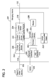
- FIG. 2 is a block diagram of an exemplary charging device that may be used with the system shown in FIG. 1 .
- FIG. 3 is a block diagram of an exemplary detection system that may be used with the charging device shown in FIG. 1 .
- FIG. 4 is a flow diagram of an exemplary method of testing a detection system that may be used with the detection system shown in FIG. 3 .
- the term “electric vehicle” refers generally to a vehicle that includes one or more electric motors. Energy used by electric vehicles may come from various sources, such as, but not limited to, an on-board rechargeable battery and/or an on-board fuel cell.
- the electric vehicle is a hybrid electric vehicle, which captures and stores energy generated, for example, by braking.
- a hybrid electric vehicle uses energy stored in an electrical source, such as a battery, to continue operating when idling to conserve fuel.
- Some hybrid electric vehicles are capable of recharging the battery by plugging into a power receptacle, such as a power outlet. Accordingly, the term “electric vehicle” as used herein may refer to a hybrid electric vehicle or any other vehicle to which electrical energy may be delivered, for example, via the power grid.
- FIG. 1 illustrates an exemplary system 100 for use in charging, or providing electricity to, an electric vehicle 102 .
- system 100 includes a charging device 104 coupled to electric vehicle 102 .
- Electric vehicle 102 includes at least one power storage device 106 , such as a battery and/or any other storage device, coupled to a motor 108 .
- electric vehicle 102 includes a vehicle controller 110 coupled to power storage device 106 .
- charging device 104 is removably coupled to power storage device 106 and to vehicle controller 110 by at least one power conduit 112 .
- charging device 104 may be coupled to power storage device 106 and/or vehicle controller 110 by any other conduit or conduits, and/or charging device 104 may be coupled to vehicle controller 110 by a wireless data link (not shown).
- power conduit 112 includes at least one conductor (not shown) for supplying electricity to power storage device 106 and/or to any other component within electric vehicle 102 , and at least one conductor (not shown) for transmitting data to, and receiving data from, vehicle controller 110 and/or any other component within electric vehicle 102 .
- power conduit 112 may include a single conductor that transmits and/or receives power and/or data, or any other number of conductors that enables system 100 to function as described herein.
- charging device 104 is coupled to an electric power source 114 , such as a power grid of an electric utility company, a generator, a battery, and/or any other device or system that provides electricity to charging device 104 .
- Charging device 104 is coupled to at least one server 116 through a network, such as the Internet, a local area network (LAN), a wide area network (WAN), and/or any other network or data connection that enables charging device 104 to function as described herein.
- Server 116 in the exemplary embodiment, communicates with charging device 104 , for example, by transmitting a signal to charging device 104 to authorize payment and/or delivery of electricity to power storage device 106 , to access customer information, and/or to perform any other function that enables system 100 to function as described herein.
- Server 116 and vehicle controller 110 each include at least one processor and at least one memory device.
- the processors each include any suitable programmable circuit which may include one or more systems and microcontrollers, microprocessors, reduced instruction set circuits (RISC), application specific integrated circuits (ASIC), programmable logic circuits (PLC), field programmable gate arrays (FPGA), and any other circuit capable of executing the functions described herein.
- RISC reduced instruction set circuits
- ASIC application specific integrated circuits
- PLC programmable logic circuits
- FPGA field programmable gate arrays
- the above examples are exemplary only, and thus are not intended to limit in any way the definition and/or meaning of the term “processor.”
- the memory devices each include a computer readable storage medium, such as, without limitation, random access memory (RAM), flash memory, a hard disk drive, a solid state drive, a diskette, a flash drive, a compact disc, a digital video disc, and/or any suitable memory device that enables the processors to store, retrieve, and/or execute instructions and/or data.
- RAM random access memory
- flash memory such as, without limitation, random access memory (RAM), flash memory, a hard disk drive, a solid state drive, a diskette, a flash drive, a compact disc, a digital video disc, and/or any suitable memory device that enables the processors to store, retrieve, and/or execute instructions and/or data.
- a user couples power storage device 106 to charging device 104 with power conduit 112 .
- the user may access a user interface (not shown in FIG. 1 ) of charging device 104 to enter information, such as payment information, and/or to initiate power delivery to power storage device 106 .
- Charging device 104 is configured to communicate with server 116 , for example, to authenticate the user, to process the payment information, and/or to approve or authorize the power delivery. If charging device 104 receives a signal from server 116 that indicates approval or authorization to deliver power to power storage device 106 , charging device 104 receives power from electric power source 114 and provides the power to power storage device 106 through power conduit 112 .
- Charging device 104 communicates with vehicle controller 110 wirelessly, through power conduit 112 , and/or through any other conduit, to control and/or to monitor the delivery of power to power storage device 106 .
- vehicle controller 110 may transmit signals to charging device 104 indicating a charge level of power storage device 106 and/or a desired amount and/or rate of power to be provided by charging device 104 .
- charging device 104 may transmit signals to vehicle controller 110 indicating an amount and/or rate of electricity being delivered to power storage device 106 .
- charging device 104 and/or vehicle controller 110 may transmit and/or receive any other signals or messages that enable system 100 to function as described herein.
- charging device 104 ceases delivering power to power storage device 106 and the user disengages power conduit 112 from power storage device 106 .
- FIG. 2 is a block diagram of an exemplary charging device 104 that may be used with system 100 (shown in FIG. 1 ).
- charging device 104 includes a controller 200 that includes a processor 202 and a memory device 204 .
- controller 200 is coupled to a network interface 206 , to a display 208 , to a user interface 210 , to a vehicle communication module 212 , and to a current control module 214 .
- Processor 202 includes any suitable programmable circuit which may include one or more systems and microcontrollers, microprocessors, reduced instruction set circuits (RISC), application specific integrated circuits (ASIC), programmable logic circuits (PLC), field programmable gate arrays (FPGA), and any other circuit capable of executing the functions described herein.
- RISC reduced instruction set circuits
- ASIC application specific integrated circuits
- PLC programmable logic circuits
- FPGA field programmable gate arrays
- Memory device 204 includes a computer readable storage medium, such as, without limitation, random access memory (RAM), flash memory, a hard disk drive, a solid state drive, a diskette, a flash drive, a compact disc, a digital video disc, and/or any suitable device that enables processor 202 to store, retrieve, and/or execute instructions and/or data.
- RAM random access memory
- flash memory such as, without limitation, a hard disk drive, a solid state drive, a diskette, a flash drive, a compact disc, a digital video disc, and/or any suitable device that enables processor 202 to store, retrieve, and/or execute instructions and/or data.
- Network interface 206 transmits and receives data between controller 200 and a remote device or system, such as server 116 (shown in FIG. 1 ).
- Network interface 206 communicates with server 116 and controller 200 using any suitable communication protocol, such as a wired and/or a wireless Ethernet protocol.
- Display 208 may include a vacuum fluorescent display (VFD) and/or one or more light-emitting diodes (LED). Additionally or alternatively, display 208 may include, without limitation, a liquid crystal display (LCD), a cathode ray tube (CRT), a plasma display, and/or any suitable visual output device capable of displaying graphical data and/or text to a user.
- a charging status of power storage device 106 shown in FIG. 1 ), payment information, user authentication information, power consumption information of charging device 104 and/or of electric vehicle 102 , fault information of charging device 104 and/or of vehicle 102 , and/or any other information may be displayed to a user on display 208 .
- User interface 210 includes, without limitation, a keyboard, a keypad, a touch-sensitive screen, a push button, a scroll wheel, a pointing device, a barcode reader, a magnetic card reader, a radio frequency identification (RFID) card reader, an audio input device employing speech-recognition software, and/or any suitable device that enables a user to input data into charging device 104 and/or to retrieve data from charging device 104 .
- the user may input user authentication information and/or payment information using user interface 210 .
- the user may operate user interface 210 to initiate and/or terminate the delivery of power to power storage device 106 .
- vehicle communication module 212 is coupled to vehicle controller 110 (shown in FIG. 1 ) by power conduit 112 or by any other conduit that enables vehicle communication module 212 to function as described herein.
- Vehicle communication module 212 transmits data to, and receives data from, vehicle controller 110 using a suitable protocol, such as power line communication (PLC), a serial communication protocol, analog voltage level detection, duty cycle measurement, and/or any other protocol that enables vehicle communication module 212 to function as described herein.
- PLC power line communication
- vehicle communication module 212 communicates with vehicle controller 110 to control and/or adjust an amount of current that power storage device 106 draws from charging device 104 .
- Current control module 214 is coupled to an input end 216 of power conduit 112 and to an output end 218 of power conduit 112 .
- Input end 216 is coupled to a power source, such as electric power source 114 (shown in FIG. 1 ), and output end 218 is coupled to a load, such as power storage device 106 .
- a power source such as electric power source 114 (shown in FIG. 1 )
- output end 218 is coupled to a load, such as power storage device 106 .
- input end 216 is coupled to a single phase of a three phase alternating current (AC) power source, such as electric power source 114 .
- input end 216 may be coupled to a direct current (DC) power source or to two or three phases of an AC power source.
- Current control module 214 includes at least one current protection device 220 , at least one current control device 222 , and at least one current sensor 224 .
- each conductor of power conduit 112 may include a separate current protection device 220 , current control device 222 , and/or current sensor 224 .
- Current protection device 220 in an exemplary embodiment, is activated to electrically isolate input end 216 from output end 218 if the current flowing through power conduit 112 exceeds a predetermined threshold or current limit. More specifically, current protection device 220 activates, or “trips,” when the current flowing through power conduit 112 exceeds a rated current limit of current protection device 220 . When current protection device 220 activates or trips, current is prevented from flowing through power conduit 112 (i.e., input end 216 is electrically isolated from output end 218 ).
- current protection device 220 is a circuit breaker. Alternatively, current protection device 220 may be a fuse, a relay, and/or any other device that enables current protection device 220 to function as described herein.
- Current control device 222 in an exemplary embodiment, is a contactor 222 coupled to current protection device 220 by power conduit 112 . Moreover, contactor 222 is coupled to, and is controlled by, controller 200 . In an exemplary embodiment, controller 200 operates contactor 222 (e.g., opens contactor 222 ) to interrupt the current flowing through power conduit 112 if a ground fault is detected and/or if a ground fault detection system (not shown in FIG. 2 ) is determined to be operating incorrectly, as more fully described herein, such that input end 216 is electrically isolated from output end 218 . As such, by operating or activating contactor 222 , controller 200 prevents current from flowing to power storage device 106 . In addition, controller 200 operates contactor 222 (e.g., closes contactor 222 ) to enable current to flow to power storage device 106 , for example, if the ground fault detection system is determined to operate correctly.
- controller 200 operates contactor 222 (e.g., closes contactor 222 ) to
- At least one current sensor 224 measures and/or detects the current transmitted through power conduit 112 during operation of charging device 104 .
- current sensor 224 is a current transformer that measures an amount of current transmitted through power conduit 112 for use in detecting one or more ground faults.
- Current sensor 224 transmits one or more signals representative of the measured and/or detected current (hereinafter referred to as “current measurement signals”) to controller 200 .
- FIG. 3 is a block diagram of an exemplary ground fault detection system 300 that may be used with, or within, charging device 104 (shown in FIG. 1 ).
- detection system 300 includes contactor 222 , current sensor 224 , and controller 200 .
- Detection system 300 determines whether one or more ground faults exist and/or performs one or more self-tests to determine whether detection system operates correctly.
- Controller 200 in an exemplary embodiment, includes a conditioning circuit 302 coupled to current sensor 224 and to processor 202 .
- conditioning circuit 302 is coupled to current sensor 224 by at least one detection conductor 304 and at least one test conductor 306 .
- Current sensor 224 transmits current measurement signals to conditioning circuit 302 and to processor 202 through detection conductor 304 .
- Processor 202 transmits one or more test signals to current sensor 224 through conditioning circuit 302 and through test conductor 306 .
- current sensor 224 may receive signals from either power conduit 112 or test conductor 306 , but not from both at the same time. Accordingly, in one embodiment, controller 200 operates contactor 222 to prevent current from flowing through power conduit 112 when the self-test is being performed (e.g., while the test signal is being generated).
- processor 202 performs a self-test of detection system 300 while contactor 222 is open (i.e., while contactor 222 prevents current from flowing through power conduit 112 ).
- Processor 202 simulates a ground fault current by transmitting a test signal to conditioning circuit 302 .
- the test signal is a pulse width modulated (PWM) square wave signal that has a duty cycle of about 50%.
- the test signal can have any other duty cycle or may be any other signal that enables detection system 300 to function as described herein.
- Conditioning circuit 302 receives the test signal and adjusts at least one characteristic of the test signal. In an exemplary embodiment, conditioning circuit 302 adjusts a voltage of the test signal such that the test signal oscillates between about ⁇ 12 volts (V) and +12 V. Alternatively, conditioning circuit 302 adjusts the voltage of the test signal such that the test signal oscillates between any other voltage range, and/or adjusts a current and/or any other characteristic of the test signal. Conditioning circuit 302 transmits the adjusted test signal to current sensor 224 through test conductor 306 .
- Current sensor 224 measures an amount of current transmitted through test conductor 306 (i.e., an amount of current of the test signal) and outputs a signal having a current that is representative of the amount of current detected within test conductor 306 (hereinafter referred to as the “test current measurement signal”). Current sensor 224 transmits the test current measurement signal to conditioning circuit 302 .
- Conditioning circuit 302 adjusts at least one characteristic of the test current measurement signal. More specifically, in an exemplary embodiment, conditioning circuit 302 removes a voltage offset of the test current measurement signal and/or adjusts a voltage of the test current measurement signal for use with processor 202 . Conditioning circuit 302 also converts the test current measurement signal from a current signal to a voltage signal having a voltage representative of the amount of current detected within test conductor 306 . Conditioning circuit 302 transmits the adjusted test current measurement signal to processor 202 .
- processor 202 samples the adjusted test current measurement signal to obtain a plurality of current measurement values representative of the current measured by current sensor 224 .
- processor 202 samples the test current measurement signal using an analog to digital converter (ADC) (not shown).
- ADC analog to digital converter
- Processor 202 calculates a square of each current measurement value and accumulates the squared current measurement values (hereinafter referred to as a “squared current value sum”) over a first, or accumulation, period of time.
- the accumulation period of time is equal to about half of a cycle (or period) of the current received from electric power source 114 .
- the accumulation period is equal to about 8.33 milliseconds (ms) (i.e., half of about 16.67 ms, which is the period of the current of electric power source 114 ).
- a second, or self-test, period of time includes a plurality of sequential accumulation periods.
- Processor 202 calculates and stores each squared current value sum in memory device 204 for each accumulation period within the self-test period.
- the self-test period of time is equal to about one second.
- the self-test period of time and/or the accumulation period of time may be any suitable time period that enables detection system 300 to function as described herein.
- processor 202 calculates an average value of the test current (hereinafter referred to as an “average current value”). More specifically, processor 202 adds each squared current value sum within the self-test period to obtain a total current sum, and divides the total current sum by the total number of samples, or current measurement values, received by processor 202 during the self-test period.
- Processor 202 then compares the average current value with a predetermined lower threshold value and a predetermined upper threshold value to determine whether detection system 300 is operating correctly (e.g., whether detection system 300 detects and/or processes the test signal correctly). If the average current value is between the lower threshold value and the upper threshold value, or is equal to the lower threshold value or the upper threshold value, processor 202 determines that detection system 300 is operating correctly by correctly detecting and/or processing the test signal generated by processor 202 . However, if the average current value is lower than the lower threshold value or is higher than the upper threshold value, processor 202 determines that detection system 300 is not operating correctly because the test signal is not properly detected and/or processed.
- processor 202 determines that detection system 300 is not operating correctly, processor 202 prevents current from being supplied to electric vehicle 102 , for example, by preventing contactor 222 from closing. In one embodiment, processor 202 also causes an error notification to be transmitted to a user or device, for example, to server 116 through a network, causes the error notification to be displayed on display 208 , and/or causes any other suitable action to be performed. However, if processor 202 determines that detection system 300 is operating correctly, processor 202 enables current to be supplied to electric vehicle 102 , for example, by closing contactor 222 to electrically couple power storage device 106 to electric power source 114 .
- FIG. 4 is a flow diagram of an exemplary method 400 for testing a detection system, such as detection system 300 (shown in FIG. 3 ).
- method 400 includes a plurality of instructions stored within memory device 204 , and is at least partially executed by processor 202 (both shown in FIG. 2 ).
- Method 400 is executed when power conduit 112 is coupled to an electric vehicle 102 (i.e., to power storage device 106 ) (both shown in FIG. 1 ). More specifically, processor 202 executes a self-test (i.e., method 400 ) of detection system 300 before contactor 222 is closed, thus enabling detection system 300 to be tested before current is supplied to power storage device 106 .
- a self-test i.e., method 400
- Processor 202 generates 401 a test signal and transmits 402 the test signal to current sensor 224 through conditioning circuit 302 and test conductor 306 (both shown in FIG. 3 ).
- the test signal is conditioned by conditioning circuit 302 to adjust the voltage of the test signal.
- Current sensor 224 generates 404 a test current measurement signal indicative of the current detected within test conductor 306 (i.e., the detected current of the test signal), and outputs the test current measurement signal to processor 202 through conditioning circuit 302 .
- Processor 202 receives 405 the test current measurement signal and samples 406 the test current measurement signal to obtain a plurality of current measurement values representative of the test signal current.
- Processor 202 calculates 408 a sum of squared current measurement values (i.e., a squared current value sum) over a first period of time (e.g., the accumulation period of time) as described above with reference to FIG. 3 .
- processor 202 calculates a squared current value sum for each accumulation period within the self-test period of time.
- Processor 202 stores 410 , within memory device 204 , each squared current value sum over the second, or self-test, period of time.
- processor 202 calculates 412 an average current value over the second period of time based on the squared current value sums, as described above with reference to FIG. 3 .
- Processor 202 determines 414 whether the average current value is within a predetermined range, such as between the lower threshold value and the upper threshold value, or equal to the lower threshold value or the upper threshold value. If processor 202 determines 414 that the average current value is within the predetermined range, processor 202 determines that a status of detection system 300 is operational, i.e., that detection system 300 is operating correctly. Accordingly, processor 202 enables 416 current to be supplied to power storage device 106 , for example, by closing contactor 222 .
- processor 202 determines 414 that the average current value is not within the predetermined range, processor 202 determines that the status of detection system 300 is non-operational or faulty, i.e., that detection system 300 is not operating correctly. Accordingly, processor 202 prevents 418 current from being supplied to power storage device 106 , for example, by preventing contactor 222 from closing. Processor 202 may also generate an error notification and/or may perform any other suitable action that enables method 400 to function as described herein.
- the charging device includes a detection system that facilitates detecting one or more ground faults within the charging device.
- the detection system also includes a processor configured to execute a self-test on the detection system to determine whether the detection system is operating correctly.
- the processor transmits a test signal to a current sensor through a test conductor, and the current sensor measures an amount of current in the test conductor.
- the current sensor transmits a current measurement signal to the processor.
- the processor calculates a square of each current value sampled from the current measurement signal and accumulates each squared value within each of a plurality of accumulation periods of time within a self-test period of time.
- the processor calculates an average current value based on the accumulated squared values, and determines whether the average current value is within a predetermined range. If the average current value is within the predetermined range, the processor determines that the detection system is operating correctly and enables current to be supplied to an electric vehicle. However, if the average current value is not within the predetermined range, the processor determines that the detection system is not operating correctly, and processor prevents current from being supplied to the electric vehicle. Accordingly, the detection system described herein facilitates verifying and maintaining effective and cost-efficient ground fault protection for the charging device.
- a technical effect of the device, system, and method described herein includes at least one of (a) generating a test signal within a detection system; (b) transmitting a test signal through a test conductor to a current sensor, wherein the current sensor is configured to detect a current within the test conductor; (c) receiving a current measurement signal from a current sensor, wherein the current measurement signal is representative of an amount of current detected within a test conductor; and (d) determining a status of a detection system based on a current measurement signal received.
- Exemplary embodiments of a charging device, detection system, and method of testing a detection system are described above in detail.
- the charging device, detection system, and method are not limited to the specific embodiments described herein, but rather, components of the charging device and/or detection system, and/or steps of the method may be utilized independently and separately from other components and/or steps described herein.
- the charging device may also be used in combination with other power systems and methods, and is not limited to practice with only the electric vehicle as described herein. Rather, an exemplary embodiment can be implemented and utilized in connection with many other power system applications.
Landscapes
- Engineering & Computer Science (AREA)
- Power Engineering (AREA)
- Transportation (AREA)
- Mechanical Engineering (AREA)
- Life Sciences & Earth Sciences (AREA)
- Sustainable Development (AREA)
- Sustainable Energy (AREA)
- Electric Propulsion And Braking For Vehicles (AREA)
- Charge And Discharge Circuits For Batteries Or The Like (AREA)
Abstract
Description
Claims (20)
Priority Applications (1)
| Application Number | Priority Date | Filing Date | Title |
|---|---|---|---|
| US13/358,672 US8854070B2 (en) | 2012-01-26 | 2012-01-26 | Charging device, detection system, and method of testing a detection system |
Applications Claiming Priority (1)
| Application Number | Priority Date | Filing Date | Title |
|---|---|---|---|
| US13/358,672 US8854070B2 (en) | 2012-01-26 | 2012-01-26 | Charging device, detection system, and method of testing a detection system |
Publications (2)
| Publication Number | Publication Date |
|---|---|
| US20130193907A1 US20130193907A1 (en) | 2013-08-01 |
| US8854070B2 true US8854070B2 (en) | 2014-10-07 |
Family
ID=48869649
Family Applications (1)
| Application Number | Title | Priority Date | Filing Date |
|---|---|---|---|
| US13/358,672 Active 2033-04-24 US8854070B2 (en) | 2012-01-26 | 2012-01-26 | Charging device, detection system, and method of testing a detection system |
Country Status (1)
| Country | Link |
|---|---|
| US (1) | US8854070B2 (en) |
Cited By (1)
| Publication number | Priority date | Publication date | Assignee | Title |
|---|---|---|---|---|
| CN108562782A (en) * | 2018-07-17 | 2018-09-21 | 国网湖南省电力有限公司 | A kind of acquisition methods of stray electrical current and the detecting system of stray electrical current |
Families Citing this family (10)
| Publication number | Priority date | Publication date | Assignee | Title |
|---|---|---|---|---|
| CN104793161B (en) * | 2014-01-17 | 2017-11-03 | 联合汽车电子有限公司 | Motor driven systems current sensor faults diagnostic method |
| US9511676B2 (en) * | 2014-01-31 | 2016-12-06 | Ford Global Technologies Llc | Portable EV energy transfer apparatus and method |
| US11137438B2 (en) | 2014-08-22 | 2021-10-05 | Disruptive Technologies | Systems and methods for testing electrical leakage |
| DE102014218764A1 (en) * | 2014-09-18 | 2016-03-24 | Siemens Aktiengesellschaft | Power transmission system and method of operating a power transmission system |
| CN105606937A (en) * | 2016-02-25 | 2016-05-25 | 北京群菱能源科技有限公司 | DC charging pile calibration device |
| US10160342B2 (en) * | 2016-03-29 | 2018-12-25 | GM Global Technology Operations LLC | Dynamic adjustment of battery current limits based on usage |
| CN108973764A (en) * | 2018-09-19 | 2018-12-11 | 杭州物电云新能源有限公司 | A kind of charging unit and the detection method for early warning that charges |
| DE102020104736A1 (en) * | 2020-02-24 | 2021-08-26 | Audi Aktiengesellschaft | Motor vehicle comprising a charging device |
| US11385631B2 (en) * | 2020-11-11 | 2022-07-12 | Honda Research Institute Europe Gmbh | Method and system for detecting faults in a charging infrastructure system for electric vehicles |
| CN114184975B (en) * | 2021-11-29 | 2023-10-27 | 国网北京市电力公司 | Detection device of alternating-current charging pile tester |
Citations (11)
| Publication number | Priority date | Publication date | Assignee | Title |
|---|---|---|---|---|
| US6984988B2 (en) | 2002-10-16 | 2006-01-10 | Yazaki Corporation | Ground-fault detecting device and insulation resistance measuring device |
| US7292042B2 (en) | 2005-07-11 | 2007-11-06 | Nissan Motor Co., Ltd. | Ground fault detector for vehicle |
| US7554333B2 (en) | 2006-01-19 | 2009-06-30 | Nissan Motor Co., Ltd. | Grounding detector |
| US7714587B2 (en) | 2007-06-29 | 2010-05-11 | Caterpillar Inc. | Systems and methods for detecting a faulty ground strap connection |
| US7808245B2 (en) | 2007-09-28 | 2010-10-05 | Caterpillar Inc | Testing method for a ground fault detector |
| US20110029144A1 (en) | 2009-07-28 | 2011-02-03 | Michael Muller | Plug-In Electric Vehicle Supply Equipment |
| WO2011031801A2 (en) | 2009-09-08 | 2011-03-17 | Aerovironment, Inc. | Electric vehicle simulator and analyzer (evsa) for electric vehicle supply equipment |
| US20120080944A1 (en) * | 2006-03-28 | 2012-04-05 | Wireless Environment, Llc. | Grid Shifting System for a Lighting Circuit |
| US20130169228A1 (en) * | 2011-12-30 | 2013-07-04 | Samya Technology Co., Ltd. | Mcu integration battery charger/discharger |
| US20130320923A1 (en) * | 2010-12-10 | 2013-12-05 | General Electric Company | Charging device and methods for controlling a charging device |
| US20140002024A1 (en) * | 2011-03-23 | 2014-01-02 | Toyota Jidosha Kabushiki Kaisha | Adapter and vehicle for performing power feeding using adapter |
-
2012
- 2012-01-26 US US13/358,672 patent/US8854070B2/en active Active
Patent Citations (11)
| Publication number | Priority date | Publication date | Assignee | Title |
|---|---|---|---|---|
| US6984988B2 (en) | 2002-10-16 | 2006-01-10 | Yazaki Corporation | Ground-fault detecting device and insulation resistance measuring device |
| US7292042B2 (en) | 2005-07-11 | 2007-11-06 | Nissan Motor Co., Ltd. | Ground fault detector for vehicle |
| US7554333B2 (en) | 2006-01-19 | 2009-06-30 | Nissan Motor Co., Ltd. | Grounding detector |
| US20120080944A1 (en) * | 2006-03-28 | 2012-04-05 | Wireless Environment, Llc. | Grid Shifting System for a Lighting Circuit |
| US7714587B2 (en) | 2007-06-29 | 2010-05-11 | Caterpillar Inc. | Systems and methods for detecting a faulty ground strap connection |
| US7808245B2 (en) | 2007-09-28 | 2010-10-05 | Caterpillar Inc | Testing method for a ground fault detector |
| US20110029144A1 (en) | 2009-07-28 | 2011-02-03 | Michael Muller | Plug-In Electric Vehicle Supply Equipment |
| WO2011031801A2 (en) | 2009-09-08 | 2011-03-17 | Aerovironment, Inc. | Electric vehicle simulator and analyzer (evsa) for electric vehicle supply equipment |
| US20130320923A1 (en) * | 2010-12-10 | 2013-12-05 | General Electric Company | Charging device and methods for controlling a charging device |
| US20140002024A1 (en) * | 2011-03-23 | 2014-01-02 | Toyota Jidosha Kabushiki Kaisha | Adapter and vehicle for performing power feeding using adapter |
| US20130169228A1 (en) * | 2011-12-30 | 2013-07-04 | Samya Technology Co., Ltd. | Mcu integration battery charger/discharger |
Cited By (2)
| Publication number | Priority date | Publication date | Assignee | Title |
|---|---|---|---|---|
| CN108562782A (en) * | 2018-07-17 | 2018-09-21 | 国网湖南省电力有限公司 | A kind of acquisition methods of stray electrical current and the detecting system of stray electrical current |
| CN108562782B (en) * | 2018-07-17 | 2020-06-16 | 国网湖南省电力有限公司 | Stray current acquisition method and stray current detection system |
Also Published As
| Publication number | Publication date |
|---|---|
| US20130193907A1 (en) | 2013-08-01 |
Similar Documents
| Publication | Publication Date | Title |
|---|---|---|
| US8854070B2 (en) | Charging device, detection system, and method of testing a detection system | |
| US11198374B2 (en) | Device and method for charging electric vehicle | |
| US20130320923A1 (en) | Charging device and methods for controlling a charging device | |
| US8633678B2 (en) | Electric vehicle supply equipment with over-current protection | |
| US9153989B2 (en) | Power monitoring system and electric vehicle | |
| US10005371B2 (en) | Grid integration with photovoltaic generation and electric vehicle charging | |
| US8332078B2 (en) | System, charging device, and method of supplying current to a power storage device | |
| US8768563B2 (en) | Electric vehicle supply equipment testing apparatus | |
| US9551755B2 (en) | Relay weld diagnostic device | |
| US20140062396A1 (en) | Methods and systems for charging an energy storage device | |
| US9804034B2 (en) | EVSE with cordset handle temperature measurement | |
| CN104816642A (en) | Portable electrified vehicle energy transfer apparatus and method | |
| CN105774558A (en) | Integrated safety detection device for electric automobile | |
| US20170158079A1 (en) | Electric vehicle quick charge control apparatus | |
| US8706312B2 (en) | Charging device and methods of authorizing a charging request | |
| KR101934938B1 (en) | Charging device, system, and method for controlling a charging device | |
| CN207875401U (en) | High-voltage interlocking detecting system | |
| KR101501918B1 (en) | A Remote Metering System for the Recharge of an Electric Vehicle | |
| JP2010239773A (en) | Charger, electric vehicle and method for detecting ground fault-short circuit in charging system | |
| US20140015456A1 (en) | Vehicle power supply device | |
| CN103180160A (en) | Device and method for estimating a touch current and protecting an electrical apparatus against such touch currents | |
| US9413178B2 (en) | Charging device and method of detecting a connection to ground | |
| CN113859000A (en) | Charging gun, charging socket and electric vehicle charging system | |
| CN104578243A (en) | A method for monitoring the DC voltage charge and a battery management system | |
| CN110816363B (en) | Device, charging pile and method for detecting the state of a motor vehicle battery |
Legal Events
| Date | Code | Title | Description |
|---|---|---|---|
| AS | Assignment |
Owner name: GENERAL ELECTRIC COMPANY, NEW YORK Free format text: ASSIGNMENT OF ASSIGNORS INTEREST;ASSIGNORS:THOMAS, CECILIA MARIA;HOOKER, JOHN KENNETH;HALL, SCOTT JEFFREY;AND OTHERS;REEL/FRAME:027598/0801 Effective date: 20120125 |
|
| FEPP | Fee payment procedure |
Free format text: PAYOR NUMBER ASSIGNED (ORIGINAL EVENT CODE: ASPN); ENTITY STATUS OF PATENT OWNER: LARGE ENTITY |
|
| STCF | Information on status: patent grant |
Free format text: PATENTED CASE |
|
| MAFP | Maintenance fee payment |
Free format text: PAYMENT OF MAINTENANCE FEE, 4TH YEAR, LARGE ENTITY (ORIGINAL EVENT CODE: M1551) Year of fee payment: 4 |
|
| AS | Assignment |
Owner name: ABB SCHWEIZ AG, SWITZERLAND Free format text: ASSIGNMENT OF ASSIGNORS INTEREST;ASSIGNOR:GENERAL ELECTRIC COMPANY;REEL/FRAME:052431/0538 Effective date: 20180720 |
|
| MAFP | Maintenance fee payment |
Free format text: PAYMENT OF MAINTENANCE FEE, 8TH YEAR, LARGE ENTITY (ORIGINAL EVENT CODE: M1552); ENTITY STATUS OF PATENT OWNER: LARGE ENTITY Year of fee payment: 8 |
|
| AS | Assignment |
Owner name: ABB B.V., NETHERLANDS Free format text: ASSIGNMENT OF ASSIGNORS INTEREST;ASSIGNOR:ABB SCHWEIZ AG;REEL/FRAME:062205/0860 Effective date: 20221010 |
|
| AS | Assignment |
Owner name: ABB E-MOBILITY B.V., NETHERLANDS Free format text: CHANGE OF NAME;ASSIGNOR:ABB B.V.;REEL/FRAME:062320/0490 Effective date: 20220101 |