EP2690296A1 - Roller bearing - Google Patents
Roller bearing Download PDFInfo
- Publication number
- EP2690296A1 EP2690296A1 EP12763012.7A EP12763012A EP2690296A1 EP 2690296 A1 EP2690296 A1 EP 2690296A1 EP 12763012 A EP12763012 A EP 12763012A EP 2690296 A1 EP2690296 A1 EP 2690296A1
- Authority
- EP
- European Patent Office
- Prior art keywords
- raceway surface
- inner ring
- coating
- manganese phosphate
- diamond
- Prior art date
- Legal status (The legal status is an assumption and is not a legal conclusion. Google has not performed a legal analysis and makes no representation as to the accuracy of the status listed.)
- Granted
Links
- 238000000576 coating method Methods 0.000 claims abstract description 119
- 239000011248 coating agent Substances 0.000 claims abstract description 106
- CPSYWNLKRDURMG-UHFFFAOYSA-L hydron;manganese(2+);phosphate Chemical compound [Mn+2].OP([O-])([O-])=O CPSYWNLKRDURMG-UHFFFAOYSA-L 0.000 claims abstract description 52
- OKTJSMMVPCPJKN-UHFFFAOYSA-N Carbon Chemical compound [C] OKTJSMMVPCPJKN-UHFFFAOYSA-N 0.000 claims abstract description 46
- 229910052799 carbon Inorganic materials 0.000 claims abstract description 46
- 238000005096 rolling process Methods 0.000 claims abstract description 30
- 230000000452 restraining effect Effects 0.000 abstract description 2
- 238000012360 testing method Methods 0.000 description 54
- 230000007704 transition Effects 0.000 description 9
- 239000010687 lubricating oil Substances 0.000 description 7
- 238000010586 diagram Methods 0.000 description 4
- 238000000691 measurement method Methods 0.000 description 4
- 206010010904 Convulsion Diseases 0.000 description 2
- 239000000314 lubricant Substances 0.000 description 2
- 238000005259 measurement Methods 0.000 description 2
- 238000000034 method Methods 0.000 description 2
- 238000004381 surface treatment Methods 0.000 description 2
- UONOETXJSWQNOL-UHFFFAOYSA-N tungsten carbide Chemical compound [W+]#[C-] UONOETXJSWQNOL-UHFFFAOYSA-N 0.000 description 2
- 230000000694 effects Effects 0.000 description 1
- 230000005611 electricity Effects 0.000 description 1
- 230000002093 peripheral effect Effects 0.000 description 1
Images


Classifications
-
- F—MECHANICAL ENGINEERING; LIGHTING; HEATING; WEAPONS; BLASTING
- F16—ENGINEERING ELEMENTS AND UNITS; GENERAL MEASURES FOR PRODUCING AND MAINTAINING EFFECTIVE FUNCTIONING OF MACHINES OR INSTALLATIONS; THERMAL INSULATION IN GENERAL
- F16C—SHAFTS; FLEXIBLE SHAFTS; ELEMENTS OR CRANKSHAFT MECHANISMS; ROTARY BODIES OTHER THAN GEARING ELEMENTS; BEARINGS
- F16C33/00—Parts of bearings; Special methods for making bearings or parts thereof
- F16C33/30—Parts of ball or roller bearings
- F16C33/58—Raceways; Race rings
- F16C33/62—Selection of substances
-
- F—MECHANICAL ENGINEERING; LIGHTING; HEATING; WEAPONS; BLASTING
- F16—ENGINEERING ELEMENTS AND UNITS; GENERAL MEASURES FOR PRODUCING AND MAINTAINING EFFECTIVE FUNCTIONING OF MACHINES OR INSTALLATIONS; THERMAL INSULATION IN GENERAL
- F16C—SHAFTS; FLEXIBLE SHAFTS; ELEMENTS OR CRANKSHAFT MECHANISMS; ROTARY BODIES OTHER THAN GEARING ELEMENTS; BEARINGS
- F16C19/00—Bearings with rolling contact, for exclusively rotary movement
- F16C19/22—Bearings with rolling contact, for exclusively rotary movement with bearing rollers essentially of the same size in one or more circular rows, e.g. needle bearings
- F16C19/225—Details of the ribs supporting the end of the rollers
-
- F—MECHANICAL ENGINEERING; LIGHTING; HEATING; WEAPONS; BLASTING
- F16—ENGINEERING ELEMENTS AND UNITS; GENERAL MEASURES FOR PRODUCING AND MAINTAINING EFFECTIVE FUNCTIONING OF MACHINES OR INSTALLATIONS; THERMAL INSULATION IN GENERAL
- F16C—SHAFTS; FLEXIBLE SHAFTS; ELEMENTS OR CRANKSHAFT MECHANISMS; ROTARY BODIES OTHER THAN GEARING ELEMENTS; BEARINGS
- F16C19/00—Bearings with rolling contact, for exclusively rotary movement
- F16C19/22—Bearings with rolling contact, for exclusively rotary movement with bearing rollers essentially of the same size in one or more circular rows, e.g. needle bearings
- F16C19/24—Bearings with rolling contact, for exclusively rotary movement with bearing rollers essentially of the same size in one or more circular rows, e.g. needle bearings for radial load mainly
- F16C19/26—Bearings with rolling contact, for exclusively rotary movement with bearing rollers essentially of the same size in one or more circular rows, e.g. needle bearings for radial load mainly with a single row of rollers
-
- F—MECHANICAL ENGINEERING; LIGHTING; HEATING; WEAPONS; BLASTING
- F16—ENGINEERING ELEMENTS AND UNITS; GENERAL MEASURES FOR PRODUCING AND MAINTAINING EFFECTIVE FUNCTIONING OF MACHINES OR INSTALLATIONS; THERMAL INSULATION IN GENERAL
- F16C—SHAFTS; FLEXIBLE SHAFTS; ELEMENTS OR CRANKSHAFT MECHANISMS; ROTARY BODIES OTHER THAN GEARING ELEMENTS; BEARINGS
- F16C33/00—Parts of bearings; Special methods for making bearings or parts thereof
- F16C33/30—Parts of ball or roller bearings
- F16C33/303—Parts of ball or roller bearings of hybrid bearings, e.g. rolling bearings with steel races and ceramic rolling elements
-
- F—MECHANICAL ENGINEERING; LIGHTING; HEATING; WEAPONS; BLASTING
- F16—ENGINEERING ELEMENTS AND UNITS; GENERAL MEASURES FOR PRODUCING AND MAINTAINING EFFECTIVE FUNCTIONING OF MACHINES OR INSTALLATIONS; THERMAL INSULATION IN GENERAL
- F16C—SHAFTS; FLEXIBLE SHAFTS; ELEMENTS OR CRANKSHAFT MECHANISMS; ROTARY BODIES OTHER THAN GEARING ELEMENTS; BEARINGS
- F16C33/00—Parts of bearings; Special methods for making bearings or parts thereof
- F16C33/30—Parts of ball or roller bearings
- F16C33/34—Rollers; Needles
-
- F—MECHANICAL ENGINEERING; LIGHTING; HEATING; WEAPONS; BLASTING
- F16—ENGINEERING ELEMENTS AND UNITS; GENERAL MEASURES FOR PRODUCING AND MAINTAINING EFFECTIVE FUNCTIONING OF MACHINES OR INSTALLATIONS; THERMAL INSULATION IN GENERAL
- F16C—SHAFTS; FLEXIBLE SHAFTS; ELEMENTS OR CRANKSHAFT MECHANISMS; ROTARY BODIES OTHER THAN GEARING ELEMENTS; BEARINGS
- F16C33/00—Parts of bearings; Special methods for making bearings or parts thereof
- F16C33/30—Parts of ball or roller bearings
- F16C33/58—Raceways; Race rings
- F16C33/583—Details of specific parts of races
- F16C33/585—Details of specific parts of races of raceways, e.g. ribs to guide the rollers
-
- F—MECHANICAL ENGINEERING; LIGHTING; HEATING; WEAPONS; BLASTING
- F16—ENGINEERING ELEMENTS AND UNITS; GENERAL MEASURES FOR PRODUCING AND MAINTAINING EFFECTIVE FUNCTIONING OF MACHINES OR INSTALLATIONS; THERMAL INSULATION IN GENERAL
- F16C—SHAFTS; FLEXIBLE SHAFTS; ELEMENTS OR CRANKSHAFT MECHANISMS; ROTARY BODIES OTHER THAN GEARING ELEMENTS; BEARINGS
- F16C2204/00—Metallic materials; Alloys
- F16C2204/60—Ferrous alloys, e.g. steel alloys
- F16C2204/74—Ferrous alloys, e.g. steel alloys with manganese as the next major constituent
-
- F—MECHANICAL ENGINEERING; LIGHTING; HEATING; WEAPONS; BLASTING
- F16—ENGINEERING ELEMENTS AND UNITS; GENERAL MEASURES FOR PRODUCING AND MAINTAINING EFFECTIVE FUNCTIONING OF MACHINES OR INSTALLATIONS; THERMAL INSULATION IN GENERAL
- F16C—SHAFTS; FLEXIBLE SHAFTS; ELEMENTS OR CRANKSHAFT MECHANISMS; ROTARY BODIES OTHER THAN GEARING ELEMENTS; BEARINGS
- F16C2206/00—Materials with ceramics, cermets, hard carbon or similar non-metallic hard materials as main constituents
- F16C2206/02—Carbon based material
- F16C2206/04—Diamond like carbon [DLC]
-
- F—MECHANICAL ENGINEERING; LIGHTING; HEATING; WEAPONS; BLASTING
- F16—ENGINEERING ELEMENTS AND UNITS; GENERAL MEASURES FOR PRODUCING AND MAINTAINING EFFECTIVE FUNCTIONING OF MACHINES OR INSTALLATIONS; THERMAL INSULATION IN GENERAL
- F16C—SHAFTS; FLEXIBLE SHAFTS; ELEMENTS OR CRANKSHAFT MECHANISMS; ROTARY BODIES OTHER THAN GEARING ELEMENTS; BEARINGS
- F16C2360/00—Engines or pumps
- F16C2360/31—Wind motors
Definitions
- the invention relates to a roller bearing for use in a wind-powered generator or the like.
- bearings disposed in, for example, gear boxes for wind-powered generation medium-size roller bearings are often used.
- a windmill for use in wind-powered generation is placed in a non-steady operation which is other than a normal power-generating operation and in which rotary torque is not transmitted to a speed increaser, when electric power is cut off due to electricity outage or the like, when a control of reducing the rotary torque is performed due to high wind or the like, etc.
- a roller bearing mounted on a high-speed shaft rotates at a high speed in a nearly non-load state, so that a raceway surface of the bearing is not supplied with sufficient lubricant and therefore smearing (a phenomenon in which a plurality of minute seizures is generated) occurs on a raceway surface of a rotary ring or rolling contact surfaces of rollers, resulting in a reduced service life of the roller bearing.
- Patent Document 1 Japanese Patent Application Publication No. 2003-156053
- the manganese phosphate coating is inferior in load bearing, and therefore has a problem that peeling easily occurs on the raceway surface or the rolling contact surfaces.
- DLC diamond-like carbon
- the friction coefficient is smaller, and therefore there occurs a problem that slippage more easily occurs between the raceway surface of the rotary ring and the rolling contact surfaces of the rollers and, therefore, occurrence of smearing cannot be sufficiently restrained.
- the invention has been made in view of the foregoing circumstances, and it is an object of the invention to provide a roller bearing capable of effectively restraining occurrence of smearing or the like.
- the roller bearing of the invention for achieving the foregoing object is characterized by comprising: a fixed ring having a fixed raceway surface; a rotary ring having a rotary raceway surface that faces the fixed raceway surface; and a plurality of rollers rollably disposed between the fixed raceway surface and the rotary raceway surface, wherein, out of the rotary raceway surface and a rolling contact surface of each of the rollers, one of the surfaces is provided with a manganese phosphate coating and the other surface is provided with a diamond-like carbon coating.
- one of the surfaces is provided with a manganese phosphate coating that is inferior in load bearing but greater in friction coefficient
- the other surface is provided with a diamond-like carbon coating that is small in friction coefficient but excellent in load bearing. That is, since the rotary raceway ring and each rolling contact surface are provided with two kinds of coatings that cover each other's shortcomings, the manganese phosphate coating that is great in friction coefficient makes slippage between the rotary raceway surface and the rolling contact surface of each roller less likely to occur, so that occurrence of smearing can be effectively restrained.
- the diamond-like carbon coating which is excellent in load bearing hardens the surface, occurrence of peeling on the surface provided with the coating can be effectively restrained.
- the one of the surfaces be the rotary raceway surface and the other surface be the rolling contact surface of each roller.
- the friction force on the coating makes it possible to efficiently transmit rotary drive force of the rotary ring to the rollers.
- a rib surface that is in sliding contact with an end surface of each roller be provided on at least one side of the rotary raceway surface in an axial direction, and that, out of the rib surface and the end surface of each roller, one of the surfaces be provided with the manganese phosphate coating and the other surface be provided with the diamond-like carbon coating.
- each roller since the rib surface of the rotary ring and the end surface of each roller are also provided with two kinds of coatings that cover each other's shortcomings, due to the manganese phosphate coating, which is great in friction coefficient, the rollers are more likely to be rotated together with the rotary ring by the sliding contact resistance between the rib surface and the end surface, so that rotary drive force of the rotary ring can be more efficiently transmitted to the rollers. Furthermore, since the diamond-like carbon coating, which is excellent in load bearing, hardens the surface, occurrence of peeling on the surface provided with the coating can be effectively restrained.
- roller bearing of the invention it is possible to effectively restrain occurrence of smearing or the like by performing a surface treatment with coating, thereby increasing the service life.
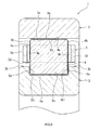
- FIG. 1 is a sectional view of a roller bearing according to a first embodiment of the invention.
- the roller bearing according to the present embodiment is a cylindrical roller bearing 1 that bears a radial load in a gearbox for wind-powered generation.
- the cylindrical roller bearing 1 includes an outer ring 2 as a fixed ring, an inner ring 3 as a rotary ring that is disposed so as to be rotatable coaxially with the outer ring 2, a plurality of cylindrical rollers 4 that are rollably disposed between the outer ring 2 and the inner ring 3, and a cage 5 for holding the cylindrical rollers 4 at predetermined intervals in circumferential direction.
- the outer ring 2 has an outer ring raceway surface (fixed raceway surface) 2a that is formed on its inner periphery, and rib portions 2b formed to be protruded radially inward at axially opposite sides of the outer ring raceway surface 2a.
- Each rib portion 2b has a rib surface 2b1 that is in sliding contact with a corresponding one of end surfaces 4b of each cylindrical roller 4 at the axially opposite sides thereof.
- an inner ring raceway surface (rotary raceway surface) 3a that faces the outer ring raceway surface 2a of the outer ring 2.
- the cylindrical rollers 4 are rollably disposed between the outer ring raceway surface 2a and the inner ring raceway surface 3a.
- An outer peripheral surface of each of the cylindrical rollers 4 is a rolling contact surface 4a that rolls on the outer ring raceway surface 2a and the inner ring raceway surface 3a.
- the cage 5 includes a first annular portion 5a and a second annular portion 5b that are disposed apart from each other in the axial direction, and a plurality of pillar portions 5c that are disposed at equal intervals in the circumferential direction of the two annular portions 5a, 5b and that connect the two annular portions 5a, 5b.
- Pockets 5d are formed between the two annular portions 5a, 5b and the adjacent pillar portions 5c.
- the cylindrical rollers 4 are disposed in these pockets 5d.
- the cage 5 retains, in the plurality of pockets 5d, the plurality of cylindrical rollers 4 at predetermined intervals in the circumferential direction.
- the outer ring raceway surface 2a of the outer ring 2, the inner ring raceway surface 3a of the inner ring 3 and the rolling contact surface 4a of each of the cylindrical rollers 4 are surface-treated with respectively different coatings. Specifically, on each of the outer ring raceway surface 2a and the inner ring raceway surface 3a, there is formed a manganese phosphate coating 6a that extends over the entire circumference of the raceway surface. Furthermore, on the rolling contact surface 4a of each cylindrical roller 4, there is formed a diamond-like carbon (DLC) coating 6b that contains, for example, tungsten carbide carbon (WCC) and that extends over the entire circumference of the roller.
- DLC diamond-like carbon
- WCC tungsten carbide carbon
- FIG. 2 is a graph showing results of an endurance test that was conducted until occurrence of peeling of the manganese phosphate coating and the diamond-like carbon coating.
- a first test piece is a test piece in which a manganese phosphate coating is formed on a flat-plate test piece made of JIS SUJ2. Furthermore, a second test piece is a test piece in which a diamond-like carbon coating is formed on a flat-plate test piece made of JIS SUJ2.
- FIG. 3 is a schematic diagram of a testing device for the endurance test.
- This testing device includes an inner ring 21 for an axial bearing which is made of JIS SUJ2 and which has an annular raceway 21a, six balls 22 of 3/8 inch made of JIS SUJ2, an annular cage 23 that holds each of the balls 22, lubricating oil 24, and a container 25 in which the first test piece 30 is disposed and the lubricating oil 24 is stored.
- the annular raceway's diameter (the diameter of a groove bottom of the raceway 21a, P.C.D.) is ⁇ 38 mm.
- the first test piece 30 was placed in the container 25 so that the manganese phosphate coating 31 (corresponding to the manganese phosphate coating 6a according to the invention) faced upward in the vertical direction, and the six balls 22 held by the cage 23 were placed on the manganese phosphate coating 31, and the inner ring 21 was put on the six balls 22 so that the balls 22 were placed within the raceway 21a.
- the lubricating oil 24 was put into the container 25 so that the first test piece 30 was completely submerged and the cage 23 was immersed up to its substantially middle position in the vertical direction.
- MEROPA WM320 in trade name (produced by Chevron) was used.
- Axial load in the direction of an arrow A shown in the drawing was applied between the first test piece 30 and the inner ring 21 so that the contact surface pressure between the balls 22 and the first test piece 30 became equal to a predetermined value, and then the first test piece 30 was immobilized and the inner ring 21 was rotated at a rotation speed of 1200 min -1 .
- the passage speed of the balls 22 at this time was 3600 min -1 .
- the contact surface pressure was intermittently raised so as to be 2.0 GPa at step S1, 2.6 GPa at step S2, 3.1 GPa at step S3, 3.5 GPa at step S4, and 4.1 GPa at step S5.
- the inner ring 21 was rotated 1 ⁇ 10 7 times.
- the test was conducted by using the second test piece 40 instead of the first test piece 30 as a test piece. That is, the second test piece 40 was placed in the container 25 so that the diamond-like carbon coating 41 (corresponding to the diamond-like carbon coating 6b according to the invention) faced upward in the vertical direction, and the six balls 22 held by the cage 23 were placed on the diamond-like carbon coating 41, and then a test similar to the test of the first test piece 30 was conducted.
- the second test piece 40 was placed in the container 25 so that the diamond-like carbon coating 41 (corresponding to the diamond-like carbon coating 6b according to the invention) faced upward in the vertical direction, and the six balls 22 held by the cage 23 were placed on the diamond-like carbon coating 41, and then a test similar to the test of the first test piece 30 was conducted.
- FIG. 4 is a graph showing transitions in friction coefficients of the manganese phosphate coating and the diamond-like carbon coating under a no-lubricant condition.
- a measurement method for the friction coefficients is as follows.
- a third test piece is a test piece in which a manganese phosphate coating is formed in a flat-plate test piece made of JIS SUJ2.
- a fourth test piece is a test piece in which a diamond-like carbon coating is formed on a flat-plate test piece made of JIS SUJ2.
- FIG. 5 is a schematic diagram showing a measuring device for measuring transitions in the friction coefficient.
- balls 51 of 3/16 inch made of JIS SUJ2 and lubricating oil (not shown) were prepared.
- a third test piece 60 was disposed so that a manganese phosphate coating 61 (corresponding to the manganese phosphate coating 6a according to the invention) faced upward in the vertical direction, and the balls 51 fixed so as not to roll were placed on the manganese phosphate coating 61.
- Lubricating oil was applied to surface of the third test piece 60.
- MEROPA WM320 in trade name produced by Chevron
- An axial load of 10 N was applied between the third test piece 60 and the balls 51 so that the contact surface pressure became equal to 1.6 GPa.
- the balls 51 were moved relative to the third test piece 60 over a distance of 10 mm at an average linear speed of 40 mm/s. This relative movement was continued as reciprocal movement shown by arrows B in FIG. 5 for 3600 s.
- a test was conducted by using the fourth test piece 70 instead of the third test piece 60 as a test piece. That is, the fourth test piece 70 was placed so that the diamond-like carbon coating 71 (corresponding to the diamond-like carbon coating 6b according to the invention) was in contact with the balls 51, and then measurement similar to the measurement on the third test piece 60 was conducted.
- the friction coefficient of the manganese phosphate coating transitions in the range of 0.4 to 0.6, whereas the friction coefficient of the diamond-like carbon coating transitions below or at 0.2. From this result, it can be understood that the manganese phosphate coating is greater in friction coefficient than the diamond-like carbon coating.
- the cylindrical roller bearing 1 With the cylindrical roller bearing 1 according to the embodiment of the invention described above, out of the inner ring raceway surface 3a of the inner ring 3, which is a rotary ring, and the rolling contact surface 4a of each cylindrical roller 4, one of the surfaces is provided with the manganese phosphate coating 6a that is inferior in load bearing but great in friction coefficient, and the other surface is provided with the diamond-like carbon coating 6b that is small in friction coefficient but excellent in load bearing. That is, on the inner ring raceway surface 3a and the rolling contact surface 4a, there are formed two kinds of coatings that cover each other's shortcomings.
- the manganese phosphate coating 6a which is great in friction coefficient, slippage is less likely to occur between the inner ring raceway surface 3a and the rolling contact surface 4a, so that occurrence of smearing (a phenomenon in which a plurality of minute seizures is generated) can be effectively restrained.
- the diamond-like carbon coating 6b which is excellent in load bearing, hardens the surface, so that occurrence of peeling on the rolling contact surface 4a provided with the coating 6b can be effectively restrained. Therefore, it becomes possible to increase the service life of the cylindrical roller bearing 1.
- the manganese phosphate coating 6a which is great in friction coefficient, is formed on the inner ring raceway surface 3a, the friction force of the manganese phosphate coating 6a makes it possible to efficiently transmit rotary drive force of the inner ring 3 to the cylindrical rollers 4.
- the rib surfaces 2b1 of the outer ring 2 as a fixed ring and the end surfaces 4b of each cylindrical roller 4 are not surface-treated with coating. Therefore, increase in the sliding contact resistance between the rib surfaces 2b1 and the cylindrical rollers 4 due to coating can be prevented.
- FIG. 6 is a sectional view showing a roller bearing according to a second embodiment of the invention.
- the present embodiment differs from the first embodiment in that rib surfaces are formed on an inner ring and that the rib surfaces and the end surfaces of cylindrical rollers are surface-treated with coating.
- the outer periphery of the inner ring 3 has rib portions 3b that are protruded radially outward at axially opposite sides of an inner ring raceway surface 3a.
- Each rib portion 3b has a rib surface 3b1 that is in sliding contact with a corresponding one of the end surfaces 4b of each cylindrical roller 4.
- the rib surfaces 3b1 of the inner ring 3 and the end surfaces 4b of each cylindrical roller 4 are surface-treated with respectively different coatings. Specifically, a manganese phosphate coating 6a is formed entirely over each rib surface 3b1. Furthermore, a diamond-like carbon (DLC) coating 6b that contains, for example, a tungsten carbide carbon (WCC) is formed entirely over each end surface 4b.
- the film thickness of each of the manganese phosphate coatings 6a and the diamond-like carbon coatings 6b is set equal to or less than 3 ⁇ m.
- each cylindrical roller 4 since the rib surfaces 3b1 of the inner ring 3 and the end surfaces 4b of each cylindrical roller 4 are provided with two kinds of coatings that cover each other's shortcomings, due to the manganese phosphate coating 6a, which is great in friction coefficient, the cylindrical rollers 4 are more likely to be rotated together with the inner ring 3 by the sliding contact resistance between the rib surfaces 3b1 and the end surfaces 4b of the cylindrical rollers 4, so that rotary drive force of the inner ring 3 can be more efficiently transmitted to the cylindrical rollers 4. Furthermore, since the diamond-like carbon coating 6b, which is excellent in load bearing, hardens the surface, occurrence of peeling on the end surfaces 4b provided with the coatings 6b can be effectively restrained.
- the invention may be carried out with changes as appropriate, without being limited to the foregoing embodiments.
- the manganese phosphate coating is formed on each of the outer ring raceway surface and the inner ring raceway surface and the diamond-like carbon coating is formed on each of the rolling contact surfaces of the cylindrical rollers
- the diamond-like carbon coating may be formed on each of the outer ring raceway surface and the inner ring raceway surface and the manganese phosphate coating may be formed on each of the rolling contact surfaces of the cylindrical rollers.
- coating is formed on each of the outer ring raceway surface and the inner ring raceway surface, it is only necessary to form coating at least on an inner ring raceway surface of a rotary ring.
- the manganese phosphate coating is formed on each rib surface and diamond-like carbon coating is formed on each of the end surfaces of the cylindrical rollers
- the diamond-like carbon coating may be formed on each rib surface and the manganese phosphate coating may be formed on each of the end surfaces of the cylindrical rollers.
- the diamond-like carbon coating is formed on each of the rolling contact surfaces and the end surfaces of the cylindrical rollers
- the diamond-like carbon coating of the rolling contact surface of a cylindrical roller may be continuous with the diamond-like carbon coatings of the end surfaces of the cylindrical roller.
- a manganese phosphate coating may be formed on each of the rolling contact surfaces and the end surfaces of the cylindrical rollers. In this case, the manganese phosphate coating of the rolling contact surface of a cylindrical roller may be continuous with the manganese phosphate coating of the end surfaces of the cylindrical roller.
- a manganese phosphate coating is formed on each of the inner ring raceway surface and the rib surfaces of the inner ring
- the manganese phosphate coating on the inner ring raceway surface of the inner ring and the manganese phosphate coating on each of the rib surfaces of the inner ring may be continuous with each other.
- a diamond-like carbon coating may be formed on each of the inner ring raceway surface and the rib surfaces of the inner ring. In this case, the diamond-like carbon coating on the inner ring raceway surface of the inner ring and the diamond-like carbon coating on each of the rib surfaces of the inner ring may be continuous with each other.
- one of the coatings may be formed on each of the inner ring raceway surface of the inner ring and the end surfaces of the cylindrical rollers, and the other coating may be formed on each of the rib surfaces of the inner ring and the rolling contact surfaces of the cylindrical rollers.
- the coating is formed over the entire end surfaces of each cylindrical roller, it is only necessary to form coating on at least a portion that is in sliding contact with a corresponding one of the rib surfaces.
- the fixed ring is the outer ring
- the rotary ring is the inner ring
- the fixed ring may be the inner ring and the rotary ring may be the outer ring.
- roller bearing is not limited to a radial cylindrical roller bearing, but may also be a thrust roller bearing or a tapered roller bearing.
Landscapes
- Engineering & Computer Science (AREA)
- General Engineering & Computer Science (AREA)
- Mechanical Engineering (AREA)
- Ceramic Engineering (AREA)
- Rolling Contact Bearings (AREA)
Abstract
Description
- The invention relates to a roller bearing for use in a wind-powered generator or the like.
- As bearings disposed in, for example, gear boxes for wind-powered generation, medium-size roller bearings are often used. There are some cases where a windmill for use in wind-powered generation is placed in a non-steady operation which is other than a normal power-generating operation and in which rotary torque is not transmitted to a speed increaser, when electric power is cut off due to electricity outage or the like, when a control of reducing the rotary torque is performed due to high wind or the like, etc. In such a case, especially, a roller bearing mounted on a high-speed shaft rotates at a high speed in a nearly non-load state, so that a raceway surface of the bearing is not supplied with sufficient lubricant and therefore smearing (a phenomenon in which a plurality of minute seizures is generated) occurs on a raceway surface of a rotary ring or rolling contact surfaces of rollers, resulting in a reduced service life of the roller bearing.
- Therefore, conventionally, in order to protect the raceway surface of the rotary ring and the rolling contact surfaces of the rollers, the raceway surface and the rolling contact surfaces are subjected to a surface treatment with manganese phosphate coating (see, for example, Patent Document 1).
- Patent Document 1: Japanese Patent Application Publication No.
2003-156053 - However, the manganese phosphate coating is inferior in load bearing, and therefore has a problem that peeling easily occurs on the raceway surface or the rolling contact surfaces. In order to solve this problem, it is conceivable to form a diamond-like carbon (DLC) coating that is excellent in load bearing, instead of the manganese phosphate coating, on the raceway surface or the like. However, in this case, the friction coefficient is smaller, and therefore there occurs a problem that slippage more easily occurs between the raceway surface of the rotary ring and the rolling contact surfaces of the rollers and, therefore, occurrence of smearing cannot be sufficiently restrained.
- The invention has been made in view of the foregoing circumstances, and it is an object of the invention to provide a roller bearing capable of effectively restraining occurrence of smearing or the like.
- The roller bearing of the invention for achieving the foregoing object is characterized by comprising: a fixed ring having a fixed raceway surface; a rotary ring having a rotary raceway surface that faces the fixed raceway surface; and a plurality of rollers rollably disposed between the fixed raceway surface and the rotary raceway surface, wherein, out of the rotary raceway surface and a rolling contact surface of each of the rollers, one of the surfaces is provided with a manganese phosphate coating and the other surface is provided with a diamond-like carbon coating.
- According to the invention, out of the rotary raceway surface of the rotary ring and the rolling contact surface of each roller, one of the surfaces is provided with a manganese phosphate coating that is inferior in load bearing but greater in friction coefficient, and the other surface is provided with a diamond-like carbon coating that is small in friction coefficient but excellent in load bearing. That is, since the rotary raceway ring and each rolling contact surface are provided with two kinds of coatings that cover each other's shortcomings, the manganese phosphate coating that is great in friction coefficient makes slippage between the rotary raceway surface and the rolling contact surface of each roller less likely to occur, so that occurrence of smearing can be effectively restrained. Furthermore, since the diamond-like carbon coating which is excellent in load bearing hardens the surface, occurrence of peeling on the surface provided with the coating can be effectively restrained.
- Furthermore, it is preferable that, in the roller bearing, the one of the surfaces be the rotary raceway surface and the other surface be the rolling contact surface of each roller.
- In this case, since the rotary raceway surface is provided with the manganese phosphate coating, which is great in friction coefficient, the friction force on the coating makes it possible to efficiently transmit rotary drive force of the rotary ring to the rollers.
- Furthermore, it is preferable that, on the rotary ring, a rib surface that is in sliding contact with an end surface of each roller be provided on at least one side of the rotary raceway surface in an axial direction, and that, out of the rib surface and the end surface of each roller, one of the surfaces be provided with the manganese phosphate coating and the other surface be provided with the diamond-like carbon coating.
- In this case, since the rib surface of the rotary ring and the end surface of each roller are also provided with two kinds of coatings that cover each other's shortcomings, due to the manganese phosphate coating, which is great in friction coefficient, the rollers are more likely to be rotated together with the rotary ring by the sliding contact resistance between the rib surface and the end surface, so that rotary drive force of the rotary ring can be more efficiently transmitted to the rollers. Furthermore, since the diamond-like carbon coating, which is excellent in load bearing, hardens the surface, occurrence of peeling on the surface provided with the coating can be effectively restrained.
- According to the roller bearing of the invention, it is possible to effectively restrain occurrence of smearing or the like by performing a surface treatment with coating, thereby increasing the service life.
-
- [
FIG. 1] FIG. 1 is sectional view showing a roller bearing according to a first embodiment of the invention. - [
FIG. 2] FIG. 2 is a graph showing results of an endurance test of coatings. - [
FIG. 3 ]FIG. 1 is a schematic diagram showing a testing device for the aforementioned endurance test. - [
FIG. 4] FIG. 4 is a graph showing transitions in friction coefficients of coatings. - [
FIG. 5] FIG. 5 is a schematic diagram showing a measuring device for measuring transitions in the friction coefficients. - [
FIG. 6] FIG. 6 is a sectional view showing a roller bearing according to a second embodiment of the invention. - Hereinafter, embodiments of the roller bearing according to the invention will be described in detail with reference to the drawings.
-
FIG. 1 is a sectional view of a roller bearing according to a first embodiment of the invention. The roller bearing according to the present embodiment is a cylindrical roller bearing 1 that bears a radial load in a gearbox for wind-powered generation. Thecylindrical roller bearing 1 includes anouter ring 2 as a fixed ring, aninner ring 3 as a rotary ring that is disposed so as to be rotatable coaxially with theouter ring 2, a plurality ofcylindrical rollers 4 that are rollably disposed between theouter ring 2 and theinner ring 3, and acage 5 for holding thecylindrical rollers 4 at predetermined intervals in circumferential direction. - The
outer ring 2 has an outer ring raceway surface (fixed raceway surface) 2a that is formed on its inner periphery, andrib portions 2b formed to be protruded radially inward at axially opposite sides of the outerring raceway surface 2a. Eachrib portion 2b has a rib surface 2b1 that is in sliding contact with a corresponding one ofend surfaces 4b of eachcylindrical roller 4 at the axially opposite sides thereof. - On the outer periphery of the
inner ring 3, there is formed an inner ring raceway surface (rotary raceway surface) 3a that faces the outerring raceway surface 2a of theouter ring 2. Thecylindrical rollers 4 are rollably disposed between the outerring raceway surface 2a and the innerring raceway surface 3a. An outer peripheral surface of each of thecylindrical rollers 4 is arolling contact surface 4a that rolls on the outerring raceway surface 2a and the innerring raceway surface 3a. - The
cage 5 includes a firstannular portion 5a and a secondannular portion 5b that are disposed apart from each other in the axial direction, and a plurality ofpillar portions 5c that are disposed at equal intervals in the circumferential direction of the twoannular portions annular portions Pockets 5d are formed between the twoannular portions adjacent pillar portions 5c. Thecylindrical rollers 4 are disposed in thesepockets 5d. Thecage 5 retains, in the plurality ofpockets 5d, the plurality ofcylindrical rollers 4 at predetermined intervals in the circumferential direction. - The outer
ring raceway surface 2a of theouter ring 2, the innerring raceway surface 3a of theinner ring 3 and therolling contact surface 4a of each of thecylindrical rollers 4 are surface-treated with respectively different coatings. Specifically, on each of the outerring raceway surface 2a and the innerring raceway surface 3a, there is formed amanganese phosphate coating 6a that extends over the entire circumference of the raceway surface. Furthermore, on therolling contact surface 4a of eachcylindrical roller 4, there is formed a diamond-like carbon (DLC)coating 6b that contains, for example, tungsten carbide carbon (WCC) and that extends over the entire circumference of the roller. The film thickness of eachmanganese phosphate coating 6a and each diamond-like carbon coating 6b is set equal to or less than 3 µm. -
FIG. 2 is a graph showing results of an endurance test that was conducted until occurrence of peeling of the manganese phosphate coating and the diamond-like carbon coating. - Conditions of this endurance test are as follows. A first test piece is a test piece in which a manganese phosphate coating is formed on a flat-plate test piece made of JIS SUJ2. Furthermore, a second test piece is a test piece in which a diamond-like carbon coating is formed on a flat-plate test piece made of JIS SUJ2.
- A method of the endurance test performed until peeling occurred on the manganese phosphate coating of the first test piece will be shown below.
-
FIG. 3 is a schematic diagram of a testing device for the endurance test. This testing device includes aninner ring 21 for an axial bearing which is made of JIS SUJ2 and which has anannular raceway 21a, sixballs 22 of 3/8 inch made of JIS SUJ2, anannular cage 23 that holds each of theballs 22, lubricatingoil 24, and a container 25 in which thefirst test piece 30 is disposed and the lubricatingoil 24 is stored. The annular raceway's diameter (the diameter of a groove bottom of theraceway 21a, P.C.D.) is φ38 mm. - The
first test piece 30 was placed in the container 25 so that the manganese phosphate coating 31 (corresponding to themanganese phosphate coating 6a according to the invention) faced upward in the vertical direction, and the sixballs 22 held by thecage 23 were placed on themanganese phosphate coating 31, and theinner ring 21 was put on the sixballs 22 so that theballs 22 were placed within theraceway 21a. The lubricatingoil 24 was put into the container 25 so that thefirst test piece 30 was completely submerged and thecage 23 was immersed up to its substantially middle position in the vertical direction. As the lubricatingoil 24, MEROPA WM320 in trade name (produced by Chevron) was used. Axial load in the direction of an arrow A shown in the drawing was applied between thefirst test piece 30 and theinner ring 21 so that the contact surface pressure between theballs 22 and thefirst test piece 30 became equal to a predetermined value, and then thefirst test piece 30 was immobilized and theinner ring 21 was rotated at a rotation speed of 1200 min-1. The passage speed of theballs 22 at this time was 3600 min-1. - In the endurance test, as shown in
FIG. 2 , the contact surface pressure was intermittently raised so as to be 2.0 GPa at step S1, 2.6 GPa at step S2, 3.1 GPa at step S3, 3.5 GPa at step S4, and 4.1 GPa at step S5. At steps S1 to S5, theinner ring 21 was rotated 1 × 10⁷ times. - A method for the endurance test performed until peeling occurred on the diamond-like carbon coating of the second test piece will be shown below.
- As shown in
FIG. 3 , in the testing device used for the endurance test performed until peeling occurred on themanganese phosphate coating 31 mentioned above, the test was conducted by using thesecond test piece 40 instead of thefirst test piece 30 as a test piece. That is, thesecond test piece 40 was placed in the container 25 so that the diamond-like carbon coating 41 (corresponding to the diamond-like carbon coating 6b according to the invention) faced upward in the vertical direction, and the sixballs 22 held by thecage 23 were placed on the diamond-like carbon coating 41, and then a test similar to the test of thefirst test piece 30 was conducted. - In
FIG. 2 , with regard to the manganese phosphate coating, peeling occurred when the contact surface pressure was 3.1 GPa, whereas, with regard to the diamond-like carbon coating, peeling occurred when the contact surface pressure was 4.1 GPa. From results of this test, it can be understood that the diamond-like carbon coating is more excellent in load bearing than the manganese phosphate coating. -
FIG. 4 is a graph showing transitions in friction coefficients of the manganese phosphate coating and the diamond-like carbon coating under a no-lubricant condition. - A measurement method for the friction coefficients is as follows. A third test piece is a test piece in which a manganese phosphate coating is formed in a flat-plate test piece made of JIS SUJ2. Furthermore, a fourth test piece is a test piece in which a diamond-like carbon coating is formed on a flat-plate test piece made of JIS SUJ2.
- A measurement method for transitions in the friction coefficient of the manganese phosphate coating of the third test piece will next be shown.
-
FIG. 5 is a schematic diagram showing a measuring device for measuring transitions in the friction coefficient. In this measuring device,balls 51 of 3/16 inch made of JIS SUJ2 and lubricating oil (not shown) were prepared. - A
third test piece 60 was disposed so that a manganese phosphate coating 61 (corresponding to themanganese phosphate coating 6a according to the invention) faced upward in the vertical direction, and theballs 51 fixed so as not to roll were placed on themanganese phosphate coating 61. Lubricating oil was applied to surface of thethird test piece 60. As the lubricating oil, MEROPA WM320 in trade name (produced by Chevron) was used. An axial load of 10 N was applied between thethird test piece 60 and theballs 51 so that the contact surface pressure became equal to 1.6 GPa. In this state, theballs 51 were moved relative to thethird test piece 60 over a distance of 10 mm at an average linear speed of 40 mm/s. This relative movement was continued as reciprocal movement shown by arrows B inFIG. 5 for 3600 s. - A measurement method for transitions in the friction coefficient of the diamond-like carbon coating of the fourth test piece will next be shown.
- As shown in
FIG. 5 , in the measuring device used in the measurement method for transitions in the friction coefficient of themanganese phosphate coating 61 described above, a test was conducted by using thefourth test piece 70 instead of thethird test piece 60 as a test piece. That is, thefourth test piece 70 was placed so that the diamond-like carbon coating 71 (corresponding to the diamond-like carbon coating 6b according to the invention) was in contact with theballs 51, and then measurement similar to the measurement on thethird test piece 60 was conducted. - In
FIG. 4 , the friction coefficient of the manganese phosphate coating transitions in the range of 0.4 to 0.6, whereas the friction coefficient of the diamond-like carbon coating transitions below or at 0.2. From this result, it can be understood that the manganese phosphate coating is greater in friction coefficient than the diamond-like carbon coating. - With the
cylindrical roller bearing 1 according to the embodiment of the invention described above, out of the innerring raceway surface 3a of theinner ring 3, which is a rotary ring, and the rollingcontact surface 4a of eachcylindrical roller 4, one of the surfaces is provided with themanganese phosphate coating 6a that is inferior in load bearing but great in friction coefficient, and the other surface is provided with the diamond-like carbon coating 6b that is small in friction coefficient but excellent in load bearing. That is, on the innerring raceway surface 3a and the rollingcontact surface 4a, there are formed two kinds of coatings that cover each other's shortcomings. Therefore, due to themanganese phosphate coating 6a, which is great in friction coefficient, slippage is less likely to occur between the innerring raceway surface 3a and the rollingcontact surface 4a, so that occurrence of smearing (a phenomenon in which a plurality of minute seizures is generated) can be effectively restrained. Furthermore, the diamond-like carbon coating 6b, which is excellent in load bearing, hardens the surface, so that occurrence of peeling on the rollingcontact surface 4a provided with thecoating 6b can be effectively restrained. Therefore, it becomes possible to increase the service life of thecylindrical roller bearing 1. - Furthermore, since the
manganese phosphate coating 6a, which is great in friction coefficient, is formed on the innerring raceway surface 3a, the friction force of themanganese phosphate coating 6a makes it possible to efficiently transmit rotary drive force of theinner ring 3 to thecylindrical rollers 4. - Note that, in the present embodiment, the rib surfaces 2b1 of the
outer ring 2 as a fixed ring and the end surfaces 4b of eachcylindrical roller 4 are not surface-treated with coating. Therefore, increase in the sliding contact resistance between the rib surfaces 2b1 and thecylindrical rollers 4 due to coating can be prevented. -
FIG. 6 is a sectional view showing a roller bearing according to a second embodiment of the invention. The present embodiment differs from the first embodiment in that rib surfaces are formed on an inner ring and that the rib surfaces and the end surfaces of cylindrical rollers are surface-treated with coating. - In the present embodiment, the outer periphery of the
inner ring 3 hasrib portions 3b that are protruded radially outward at axially opposite sides of an innerring raceway surface 3a. Eachrib portion 3b has a rib surface 3b1 that is in sliding contact with a corresponding one of the end surfaces 4b of eachcylindrical roller 4. - The rib surfaces 3b1 of the
inner ring 3 and the end surfaces 4b of eachcylindrical roller 4 are surface-treated with respectively different coatings. Specifically, amanganese phosphate coating 6a is formed entirely over each rib surface 3b1. Furthermore, a diamond-like carbon (DLC)coating 6b that contains, for example, a tungsten carbide carbon (WCC) is formed entirely over eachend surface 4b. The film thickness of each of themanganese phosphate coatings 6a and the diamond-like carbon coatings 6b is set equal to or less than 3 µm. - Similarly to the embodiment of the invention described above, since the inner
ring raceway surface 3a of theinner ring 3 and the rollingcontact surface 4a of eachcylindrical roller 4 are surface-treated with themanganese phosphate coating 6a and the diamond-like carbon coating 6b, respectively, occurrence of smearing or the like on the innerring raceway surface 3a and the rollingcontact surface 4a can be effectively prevented, and therefore it becomes possible to increase the service life of thecylindrical roller bearing 1. - Furthermore, since the rib surfaces 3b1 of the
inner ring 3 and the end surfaces 4b of eachcylindrical roller 4 are provided with two kinds of coatings that cover each other's shortcomings, due to themanganese phosphate coating 6a, which is great in friction coefficient, thecylindrical rollers 4 are more likely to be rotated together with theinner ring 3 by the sliding contact resistance between the rib surfaces 3b1 and the end surfaces 4b of thecylindrical rollers 4, so that rotary drive force of theinner ring 3 can be more efficiently transmitted to thecylindrical rollers 4. Furthermore, since the diamond-like carbon coating 6b, which is excellent in load bearing, hardens the surface, occurrence of peeling on theend surfaces 4b provided with thecoatings 6b can be effectively restrained. - Note that, the invention may be carried out with changes as appropriate, without being limited to the foregoing embodiments. For example, although in the foregoing embodiments, the manganese phosphate coating is formed on each of the outer ring raceway surface and the inner ring raceway surface and the diamond-like carbon coating is formed on each of the rolling contact surfaces of the cylindrical rollers, the diamond-like carbon coating may be formed on each of the outer ring raceway surface and the inner ring raceway surface and the manganese phosphate coating may be formed on each of the rolling contact surfaces of the cylindrical rollers.
- Furthermore, although in the foregoing embodiments, coating is formed on each of the outer ring raceway surface and the inner ring raceway surface, it is only necessary to form coating at least on an inner ring raceway surface of a rotary ring.
- Furthermore, although in the second embodiment, the manganese phosphate coating is formed on each rib surface and diamond-like carbon coating is formed on each of the end surfaces of the cylindrical rollers, the diamond-like carbon coating may be formed on each rib surface and the manganese phosphate coating may be formed on each of the end surfaces of the cylindrical rollers.
- Furthermore although in the second embodiment, the diamond-like carbon coating is formed on each of the rolling contact surfaces and the end surfaces of the cylindrical rollers, the diamond-like carbon coating of the rolling contact surface of a cylindrical roller may be continuous with the diamond-like carbon coatings of the end surfaces of the cylindrical roller. Furthermore, a manganese phosphate coating may be formed on each of the rolling contact surfaces and the end surfaces of the cylindrical rollers. In this case, the manganese phosphate coating of the rolling contact surface of a cylindrical roller may be continuous with the manganese phosphate coating of the end surfaces of the cylindrical roller.
- Furthermore, although in the second embodiment, a manganese phosphate coating is formed on each of the inner ring raceway surface and the rib surfaces of the inner ring, the manganese phosphate coating on the inner ring raceway surface of the inner ring and the manganese phosphate coating on each of the rib surfaces of the inner ring may be continuous with each other. Furthermore, a diamond-like carbon coating may be formed on each of the inner ring raceway surface and the rib surfaces of the inner ring. In this case, the diamond-like carbon coating on the inner ring raceway surface of the inner ring and the diamond-like carbon coating on each of the rib surfaces of the inner ring may be continuous with each other.
- Furthermore, out of the diamond-like carbon coating and the manganese phosphate coating, one of the coatings may be formed on each of the inner ring raceway surface of the inner ring and the end surfaces of the cylindrical rollers, and the other coating may be formed on each of the rib surfaces of the inner ring and the rolling contact surfaces of the cylindrical rollers.
- Furthermore, although in the second embodiment, the coating is formed over the entire end surfaces of each cylindrical roller, it is only necessary to form coating on at least a portion that is in sliding contact with a corresponding one of the rib surfaces.
- Furthermore, although in each of the cylindrical roller bearings in the foregoing embodiments, the fixed ring is the outer ring, and the rotary ring is the inner ring, the fixed ring may be the inner ring and the rotary ring may be the outer ring.
- Furthermore, the roller bearing is not limited to a radial cylindrical roller bearing, but may also be a thrust roller bearing or a tapered roller bearing.
-
- 1:
- CYLINDRICAL ROLLER BEARING (ROLLER BEARING)
- 2:
- OUTER RING (FIXED RING)
- 2a:
- OUTER RING RACEWAY SURFACE (FIXED RACEWAY SURFACE)
- 2b1:
- RIB SURFACE
- 3:
- INNER RING (ROTARY RING)
- 3a:
- INNER RING RACEWAY SURFACE (ROTARY RACEWAY SURFACE)
- 3b1:
- RIB SURFACE
- 4:
- CYLINDRICAL ROLLER (ROLLER)
- 4a:
- ROLLING CONTACT SURFACE
- 4b:
- END SURFACE
- 6a:
- MANGANESE PHOSPHATE COATING
- 6b:
- DIAMOND-LIKE CARBON COATING
Claims (3)
- A roller bearing, characterized by comprising:a fixed ring having a fixed raceway surface;a rotary ring having a rotary raceway surface that faces the fixed raceway surface; anda plurality of rollers rollably disposed between the fixed raceway surface and the rotary raceway surface,wherein, out of the rotary raceway surface and a rolling contact surface of each of the rollers, one of the surfaces is provided with a manganese phosphate coating and the other surface is provided with a diamond-like carbon coating.
- The roller bearing according to claim 1, wherein:the one of the surfaces is the rotary raceway surface; andthe other surface is the rolling contact surface of each of the rollers.
- The roller bearing according to claim 1 or 2, wherein:on the rotary ring, a rib surface that is in sliding contact with an end surface of each of the rollers is provided on at least one side of the rotary raceway surface in an axial direction; andout of the rib surface and the end surface of each of the rollers, one of the surfaces is provided with the manganese phosphate coating and the other surface is provided with the diamond-like carbon coating.
Applications Claiming Priority (3)
| Application Number | Priority Date | Filing Date | Title |
|---|---|---|---|
| JP2011067840 | 2011-03-25 | ||
| JP2012030597A JP2012215289A (en) | 2011-03-25 | 2012-02-15 | Roller bearing |
| PCT/JP2012/056899 WO2012132968A1 (en) | 2011-03-25 | 2012-03-16 | Roller bearing |
Publications (3)
| Publication Number | Publication Date |
|---|---|
| EP2690296A1 true EP2690296A1 (en) | 2014-01-29 |
| EP2690296A4 EP2690296A4 (en) | 2015-03-11 |
| EP2690296B1 EP2690296B1 (en) | 2018-05-02 |
Family
ID=46930701
Family Applications (1)
| Application Number | Title | Priority Date | Filing Date |
|---|---|---|---|
| EP12763012.7A Not-in-force EP2690296B1 (en) | 2011-03-25 | 2012-03-16 | Roller bearing |
Country Status (5)
| Country | Link |
|---|---|
| US (1) | US8801292B2 (en) |
| EP (1) | EP2690296B1 (en) |
| JP (1) | JP2012215289A (en) |
| CN (1) | CN103429916A (en) |
| WO (1) | WO2012132968A1 (en) |
Cited By (1)
| Publication number | Priority date | Publication date | Assignee | Title |
|---|---|---|---|---|
| ITUB20152178A1 (en) * | 2015-07-15 | 2017-01-15 | Skf Ab | BEARING GROUP - HUB WITH COATED ROLLING BODIES |
Families Citing this family (12)
| Publication number | Priority date | Publication date | Assignee | Title |
|---|---|---|---|---|
| JP2014163481A (en) * | 2013-02-27 | 2014-09-08 | Nsk Ltd | Double row type cylindrical roller bearing for sintering pallet truck |
| JP2014228026A (en) * | 2013-05-20 | 2014-12-08 | 株式会社ジェイテクト | Roller for bearing, roller bearing, and method of manufacturing roller for bearing |
| DE102013225398B4 (en) * | 2013-12-10 | 2017-05-11 | Eagleburgmann Germany Gmbh & Co. Kg | Bearing component with diamond inner coating |
| DE102014019767B3 (en) * | 2014-04-01 | 2020-07-09 | Thyssenkrupp Ag | roller bearing |
| DE102014104563B4 (en) * | 2014-04-01 | 2022-04-21 | Thyssenkrupp Ag | roller bearing |
| CN106308434B (en) * | 2015-07-07 | 2019-07-30 | 深圳市联创三金电器有限公司 | Horizontal juicer with flat support structure |
| DE102016209695A1 (en) * | 2016-06-02 | 2017-12-07 | Schaeffler Technologies AG & Co. KG | Rolling bearing with a coating |
| CN109937308B (en) * | 2016-11-08 | 2022-05-03 | 开利公司 | Hybrid bearing |
| DE102017222919A1 (en) * | 2017-12-15 | 2019-06-19 | Aktiebolaget Skf | Rolling |
| DE102017222918A1 (en) * | 2017-12-15 | 2019-06-19 | Aktiebolaget Skf | roller bearing assembly |
| US11280373B2 (en) * | 2018-02-13 | 2022-03-22 | Schaeffler Technologies AG & Co. KG | Coated bearing components |
| FR3122228B1 (en) * | 2021-04-22 | 2023-04-21 | Skf Svenska Kullagerfab Ab | Improved bearing life |
Family Cites Families (17)
| Publication number | Priority date | Publication date | Assignee | Title |
|---|---|---|---|---|
| US5067826A (en) * | 1987-03-31 | 1991-11-26 | Lemelson Jerome H | Ball and roller bearings and bearing components |
| JP2991834B2 (en) * | 1991-10-14 | 1999-12-20 | 正二郎 三宅 | Rolling bearing |
| JP2001074043A (en) | 1999-09-03 | 2001-03-23 | Koyo Seiko Co Ltd | Eccentric thrust bearing |
| JP2001073967A (en) | 1999-09-03 | 2001-03-21 | Koyo Seiko Co Ltd | Eccentric thrust bearing |
| JP2001082463A (en) | 1999-09-09 | 2001-03-27 | Koyo Seiko Co Ltd | Eccentric thrust bearing |
| JP2001082466A (en) | 1999-09-17 | 2001-03-27 | Koyo Seiko Co Ltd | Roller bearing |
| JP2001124090A (en) | 1999-11-01 | 2001-05-08 | Koyo Seiko Co Ltd | Eccentric thrust bearing |
| JP2002181050A (en) * | 2000-03-16 | 2002-06-26 | Nsk Ltd | Rolling sliding member, manufacturing method thereof, and rolling sliding unit |
| JP3728491B2 (en) | 2000-03-27 | 2005-12-21 | 光洋精工株式会社 | Cam follower |
| US6994474B2 (en) * | 2001-05-29 | 2006-02-07 | Nsk Ltd. | Rolling sliding member and rolling apparatus |
| JP2003111990A (en) * | 2001-10-09 | 2003-04-15 | Brother Ind Ltd | sewing machine |
| JP2003156053A (en) * | 2001-11-22 | 2003-05-30 | Koyo Seiko Co Ltd | Swivel bearing |
| JP2003322149A (en) | 2002-05-08 | 2003-11-14 | Koyo Seiko Co Ltd | Eccentric thrust bearing |
| JP2004332915A (en) | 2002-12-12 | 2004-11-25 | Nissan Motor Co Ltd | Roller bearing |
| JP2008298171A (en) * | 2007-05-31 | 2008-12-11 | Nsk Ltd | Cylindrical roller bearing with flange |
| JP2008309312A (en) * | 2007-06-18 | 2008-12-25 | Ntn Corp | Roller bearing and rotary shaft support structure of wind power generator |
| DE102007060906B3 (en) * | 2007-12-14 | 2009-10-15 | Ab Skf | Bearing arrangement for a carrying roller |
-
2012
- 2012-02-15 JP JP2012030597A patent/JP2012215289A/en active Pending
- 2012-03-16 WO PCT/JP2012/056899 patent/WO2012132968A1/en not_active Ceased
- 2012-03-16 CN CN2012800123960A patent/CN103429916A/en active Pending
- 2012-03-16 US US14/003,615 patent/US8801292B2/en not_active Expired - Fee Related
- 2012-03-16 EP EP12763012.7A patent/EP2690296B1/en not_active Not-in-force
Cited By (1)
| Publication number | Priority date | Publication date | Assignee | Title |
|---|---|---|---|---|
| ITUB20152178A1 (en) * | 2015-07-15 | 2017-01-15 | Skf Ab | BEARING GROUP - HUB WITH COATED ROLLING BODIES |
Also Published As
| Publication number | Publication date |
|---|---|
| EP2690296B1 (en) | 2018-05-02 |
| US20130343690A1 (en) | 2013-12-26 |
| US8801292B2 (en) | 2014-08-12 |
| CN103429916A (en) | 2013-12-04 |
| EP2690296A4 (en) | 2015-03-11 |
| WO2012132968A1 (en) | 2012-10-04 |
| JP2012215289A (en) | 2012-11-08 |
Similar Documents
| Publication | Publication Date | Title |
|---|---|---|
| EP2690296B1 (en) | Roller bearing | |
| EP2690297B1 (en) | Roller bearing | |
| US9541126B2 (en) | Large rolling bearing | |
| EP3511588A1 (en) | Bearing with seal | |
| WO2014141946A1 (en) | Shaft coupling device and wind power generation device | |
| JP6155713B2 (en) | One-way clutch for wind power generator and wind power generator | |
| US9829053B2 (en) | One-way clutch and one-way clutch unit for wind power generation device | |
| CN201106625Y (en) | A thrust bearing for a high-speed aluminum foil rolling mill | |
| CN105143666B (en) | Clutch unit and wind power plant | |
| JP2011174538A (en) | Roller bearing | |
| JP4730168B2 (en) | Test method for radial rolling bearings | |
| JP2013053713A (en) | Roller bearing and wind power generator speed increasing gear | |
| WO2014141943A1 (en) | Clutch unit assembly method | |
| CN103790936A (en) | Angular contact ball bearing | |
| Van Rensselar | EXTENDING WIND TURBINE GEARBOX LIFE WITH LUBRICANTS. | |
| JP2007192330A (en) | Rolling bearing | |
| JP6398183B2 (en) | Shaft coupling device and wind power generator | |
| CN202883704U (en) | Angular contact ball bearing | |
| JP2008303893A (en) | Cylindrical roller bearing | |
| RU169240U1 (en) | BEARING BALL BEAR RADIALLY THrust TWO-ROW THIN-WALLED | |
| JP2006214520A (en) | Gearing gear bearing equipment | |
| JP6064690B2 (en) | Wind power generator | |
| CN101761553A (en) | Dual-roller bearing | |
| JP2007232076A (en) | Roller bearing | |
| JP2014173545A (en) | Shaft coupling device and wind power generation device |
Legal Events
| Date | Code | Title | Description |
|---|---|---|---|
| PUAI | Public reference made under article 153(3) epc to a published international application that has entered the european phase |
Free format text: ORIGINAL CODE: 0009012 |
|
| 17P | Request for examination filed |
Effective date: 20130924 |
|
| AK | Designated contracting states |
Kind code of ref document: A1 Designated state(s): AL AT BE BG CH CY CZ DE DK EE ES FI FR GB GR HR HU IE IS IT LI LT LU LV MC MK MT NL NO PL PT RO RS SE SI SK SM TR |
|
| DAX | Request for extension of the european patent (deleted) | ||
| A4 | Supplementary search report drawn up and despatched |
Effective date: 20150209 |
|
| RIC1 | Information provided on ipc code assigned before grant |
Ipc: F16C 19/26 20060101ALI20150203BHEP Ipc: F16C 33/66 20060101AFI20150203BHEP Ipc: C23C 22/18 20060101ALI20150203BHEP Ipc: F16C 33/34 20060101ALI20150203BHEP Ipc: F16C 19/22 20060101ALI20150203BHEP Ipc: C01B 31/02 20060101ALI20150203BHEP Ipc: F16C 33/30 20060101ALI20150203BHEP Ipc: F16C 33/58 20060101ALI20150203BHEP |
|
| RIC1 | Information provided on ipc code assigned before grant |
Ipc: F16C 33/58 20060101ALI20170713BHEP Ipc: F16C 33/30 20060101ALI20170713BHEP Ipc: F16C 33/66 20060101AFI20170713BHEP Ipc: F16C 19/26 20060101ALI20170713BHEP Ipc: C23C 22/18 20060101ALI20170713BHEP Ipc: F16C 33/34 20060101ALI20170713BHEP Ipc: F16C 19/22 20060101ALI20170713BHEP |
|
| GRAP | Despatch of communication of intention to grant a patent |
Free format text: ORIGINAL CODE: EPIDOSNIGR1 |
|
| STAA | Information on the status of an ep patent application or granted ep patent |
Free format text: STATUS: GRANT OF PATENT IS INTENDED |
|
| INTG | Intention to grant announced |
Effective date: 20171122 |
|
| GRAS | Grant fee paid |
Free format text: ORIGINAL CODE: EPIDOSNIGR3 |
|
| GRAA | (expected) grant |
Free format text: ORIGINAL CODE: 0009210 |
|
| STAA | Information on the status of an ep patent application or granted ep patent |
Free format text: STATUS: THE PATENT HAS BEEN GRANTED |
|
| AK | Designated contracting states |
Kind code of ref document: B1 Designated state(s): AL AT BE BG CH CY CZ DE DK EE ES FI FR GB GR HR HU IE IS IT LI LT LU LV MC MK MT NL NO PL PT RO RS SE SI SK SM TR |
|
| REG | Reference to a national code |
Ref country code: GB Ref legal event code: FG4D |
|
| REG | Reference to a national code |
Ref country code: CH Ref legal event code: EP Ref country code: AT Ref legal event code: REF Ref document number: 995587 Country of ref document: AT Kind code of ref document: T Effective date: 20180515 |
|
| REG | Reference to a national code |
Ref country code: DE Ref legal event code: R096 Ref document number: 602012045953 Country of ref document: DE Ref country code: IE Ref legal event code: FG4D |
|
| REG | Reference to a national code |
Ref country code: NL Ref legal event code: MP Effective date: 20180502 |
|
| REG | Reference to a national code |
Ref country code: LT Ref legal event code: MG4D |
|
| PG25 | Lapsed in a contracting state [announced via postgrant information from national office to epo] |
Ref country code: BG Free format text: LAPSE BECAUSE OF FAILURE TO SUBMIT A TRANSLATION OF THE DESCRIPTION OR TO PAY THE FEE WITHIN THE PRESCRIBED TIME-LIMIT Effective date: 20180802 Ref country code: NO Free format text: LAPSE BECAUSE OF FAILURE TO SUBMIT A TRANSLATION OF THE DESCRIPTION OR TO PAY THE FEE WITHIN THE PRESCRIBED TIME-LIMIT Effective date: 20180802 Ref country code: FI Free format text: LAPSE BECAUSE OF FAILURE TO SUBMIT A TRANSLATION OF THE DESCRIPTION OR TO PAY THE FEE WITHIN THE PRESCRIBED TIME-LIMIT Effective date: 20180502 Ref country code: SE Free format text: LAPSE BECAUSE OF FAILURE TO SUBMIT A TRANSLATION OF THE DESCRIPTION OR TO PAY THE FEE WITHIN THE PRESCRIBED TIME-LIMIT Effective date: 20180502 Ref country code: ES Free format text: LAPSE BECAUSE OF FAILURE TO SUBMIT A TRANSLATION OF THE DESCRIPTION OR TO PAY THE FEE WITHIN THE PRESCRIBED TIME-LIMIT Effective date: 20180502 Ref country code: LT Free format text: LAPSE BECAUSE OF FAILURE TO SUBMIT A TRANSLATION OF THE DESCRIPTION OR TO PAY THE FEE WITHIN THE PRESCRIBED TIME-LIMIT Effective date: 20180502 |
|
| PG25 | Lapsed in a contracting state [announced via postgrant information from national office to epo] |
Ref country code: LV Free format text: LAPSE BECAUSE OF FAILURE TO SUBMIT A TRANSLATION OF THE DESCRIPTION OR TO PAY THE FEE WITHIN THE PRESCRIBED TIME-LIMIT Effective date: 20180502 Ref country code: NL Free format text: LAPSE BECAUSE OF FAILURE TO SUBMIT A TRANSLATION OF THE DESCRIPTION OR TO PAY THE FEE WITHIN THE PRESCRIBED TIME-LIMIT Effective date: 20180502 Ref country code: RS Free format text: LAPSE BECAUSE OF FAILURE TO SUBMIT A TRANSLATION OF THE DESCRIPTION OR TO PAY THE FEE WITHIN THE PRESCRIBED TIME-LIMIT Effective date: 20180502 Ref country code: GR Free format text: LAPSE BECAUSE OF FAILURE TO SUBMIT A TRANSLATION OF THE DESCRIPTION OR TO PAY THE FEE WITHIN THE PRESCRIBED TIME-LIMIT Effective date: 20180803 Ref country code: HR Free format text: LAPSE BECAUSE OF FAILURE TO SUBMIT A TRANSLATION OF THE DESCRIPTION OR TO PAY THE FEE WITHIN THE PRESCRIBED TIME-LIMIT Effective date: 20180502 |
|
| REG | Reference to a national code |
Ref country code: AT Ref legal event code: MK05 Ref document number: 995587 Country of ref document: AT Kind code of ref document: T Effective date: 20180502 |
|
| PG25 | Lapsed in a contracting state [announced via postgrant information from national office to epo] |
Ref country code: EE Free format text: LAPSE BECAUSE OF FAILURE TO SUBMIT A TRANSLATION OF THE DESCRIPTION OR TO PAY THE FEE WITHIN THE PRESCRIBED TIME-LIMIT Effective date: 20180502 Ref country code: PL Free format text: LAPSE BECAUSE OF FAILURE TO SUBMIT A TRANSLATION OF THE DESCRIPTION OR TO PAY THE FEE WITHIN THE PRESCRIBED TIME-LIMIT Effective date: 20180502 Ref country code: AT Free format text: LAPSE BECAUSE OF FAILURE TO SUBMIT A TRANSLATION OF THE DESCRIPTION OR TO PAY THE FEE WITHIN THE PRESCRIBED TIME-LIMIT Effective date: 20180502 Ref country code: RO Free format text: LAPSE BECAUSE OF FAILURE TO SUBMIT A TRANSLATION OF THE DESCRIPTION OR TO PAY THE FEE WITHIN THE PRESCRIBED TIME-LIMIT Effective date: 20180502 Ref country code: CZ Free format text: LAPSE BECAUSE OF FAILURE TO SUBMIT A TRANSLATION OF THE DESCRIPTION OR TO PAY THE FEE WITHIN THE PRESCRIBED TIME-LIMIT Effective date: 20180502 Ref country code: SK Free format text: LAPSE BECAUSE OF FAILURE TO SUBMIT A TRANSLATION OF THE DESCRIPTION OR TO PAY THE FEE WITHIN THE PRESCRIBED TIME-LIMIT Effective date: 20180502 Ref country code: DK Free format text: LAPSE BECAUSE OF FAILURE TO SUBMIT A TRANSLATION OF THE DESCRIPTION OR TO PAY THE FEE WITHIN THE PRESCRIBED TIME-LIMIT Effective date: 20180502 |
|
| REG | Reference to a national code |
Ref country code: DE Ref legal event code: R097 Ref document number: 602012045953 Country of ref document: DE |
|
| PG25 | Lapsed in a contracting state [announced via postgrant information from national office to epo] |
Ref country code: SM Free format text: LAPSE BECAUSE OF FAILURE TO SUBMIT A TRANSLATION OF THE DESCRIPTION OR TO PAY THE FEE WITHIN THE PRESCRIBED TIME-LIMIT Effective date: 20180502 Ref country code: IT Free format text: LAPSE BECAUSE OF FAILURE TO SUBMIT A TRANSLATION OF THE DESCRIPTION OR TO PAY THE FEE WITHIN THE PRESCRIBED TIME-LIMIT Effective date: 20180502 |
|
| PLBE | No opposition filed within time limit |
Free format text: ORIGINAL CODE: 0009261 |
|
| STAA | Information on the status of an ep patent application or granted ep patent |
Free format text: STATUS: NO OPPOSITION FILED WITHIN TIME LIMIT |
|
| 26N | No opposition filed |
Effective date: 20190205 |
|
| PG25 | Lapsed in a contracting state [announced via postgrant information from national office to epo] |
Ref country code: SI Free format text: LAPSE BECAUSE OF FAILURE TO SUBMIT A TRANSLATION OF THE DESCRIPTION OR TO PAY THE FEE WITHIN THE PRESCRIBED TIME-LIMIT Effective date: 20180502 |
|
| REG | Reference to a national code |
Ref country code: DE Ref legal event code: R119 Ref document number: 602012045953 Country of ref document: DE |
|
| PG25 | Lapsed in a contracting state [announced via postgrant information from national office to epo] |
Ref country code: MC Free format text: LAPSE BECAUSE OF FAILURE TO SUBMIT A TRANSLATION OF THE DESCRIPTION OR TO PAY THE FEE WITHIN THE PRESCRIBED TIME-LIMIT Effective date: 20180502 |
|
| REG | Reference to a national code |
Ref country code: CH Ref legal event code: PL |
|
| GBPC | Gb: european patent ceased through non-payment of renewal fee |
Effective date: 20190316 |
|
| PG25 | Lapsed in a contracting state [announced via postgrant information from national office to epo] |
Ref country code: AL Free format text: LAPSE BECAUSE OF FAILURE TO SUBMIT A TRANSLATION OF THE DESCRIPTION OR TO PAY THE FEE WITHIN THE PRESCRIBED TIME-LIMIT Effective date: 20180502 Ref country code: LU Free format text: LAPSE BECAUSE OF NON-PAYMENT OF DUE FEES Effective date: 20190316 |
|
| REG | Reference to a national code |
Ref country code: BE Ref legal event code: MM Effective date: 20190331 |
|
| PG25 | Lapsed in a contracting state [announced via postgrant information from national office to epo] |
Ref country code: CH Free format text: LAPSE BECAUSE OF NON-PAYMENT OF DUE FEES Effective date: 20190331 Ref country code: DE Free format text: LAPSE BECAUSE OF NON-PAYMENT OF DUE FEES Effective date: 20191001 Ref country code: LI Free format text: LAPSE BECAUSE OF NON-PAYMENT OF DUE FEES Effective date: 20190331 Ref country code: GB Free format text: LAPSE BECAUSE OF NON-PAYMENT OF DUE FEES Effective date: 20190316 Ref country code: IE Free format text: LAPSE BECAUSE OF NON-PAYMENT OF DUE FEES Effective date: 20190316 |
|
| PG25 | Lapsed in a contracting state [announced via postgrant information from national office to epo] |
Ref country code: BE Free format text: LAPSE BECAUSE OF NON-PAYMENT OF DUE FEES Effective date: 20190331 Ref country code: FR Free format text: LAPSE BECAUSE OF NON-PAYMENT OF DUE FEES Effective date: 20190331 |
|
| PG25 | Lapsed in a contracting state [announced via postgrant information from national office to epo] |
Ref country code: TR Free format text: LAPSE BECAUSE OF FAILURE TO SUBMIT A TRANSLATION OF THE DESCRIPTION OR TO PAY THE FEE WITHIN THE PRESCRIBED TIME-LIMIT Effective date: 20180502 |
|
| PG25 | Lapsed in a contracting state [announced via postgrant information from national office to epo] |
Ref country code: PT Free format text: LAPSE BECAUSE OF FAILURE TO SUBMIT A TRANSLATION OF THE DESCRIPTION OR TO PAY THE FEE WITHIN THE PRESCRIBED TIME-LIMIT Effective date: 20180903 Ref country code: MT Free format text: LAPSE BECAUSE OF NON-PAYMENT OF DUE FEES Effective date: 20190316 |
|
| PG25 | Lapsed in a contracting state [announced via postgrant information from national office to epo] |
Ref country code: CY Free format text: LAPSE BECAUSE OF FAILURE TO SUBMIT A TRANSLATION OF THE DESCRIPTION OR TO PAY THE FEE WITHIN THE PRESCRIBED TIME-LIMIT Effective date: 20180502 |
|
| PG25 | Lapsed in a contracting state [announced via postgrant information from national office to epo] |
Ref country code: IS Free format text: LAPSE BECAUSE OF FAILURE TO SUBMIT A TRANSLATION OF THE DESCRIPTION OR TO PAY THE FEE WITHIN THE PRESCRIBED TIME-LIMIT Effective date: 20180902 |
|
| PG25 | Lapsed in a contracting state [announced via postgrant information from national office to epo] |
Ref country code: HU Free format text: LAPSE BECAUSE OF FAILURE TO SUBMIT A TRANSLATION OF THE DESCRIPTION OR TO PAY THE FEE WITHIN THE PRESCRIBED TIME-LIMIT; INVALID AB INITIO Effective date: 20120316 |
|
| PG25 | Lapsed in a contracting state [announced via postgrant information from national office to epo] |
Ref country code: MK Free format text: LAPSE BECAUSE OF FAILURE TO SUBMIT A TRANSLATION OF THE DESCRIPTION OR TO PAY THE FEE WITHIN THE PRESCRIBED TIME-LIMIT Effective date: 20180502 |