EP2690014A1 - Sealing device for galley hard point - Google Patents
Sealing device for galley hard point Download PDFInfo
- Publication number
- EP2690014A1 EP2690014A1 EP12177515.9A EP12177515A EP2690014A1 EP 2690014 A1 EP2690014 A1 EP 2690014A1 EP 12177515 A EP12177515 A EP 12177515A EP 2690014 A1 EP2690014 A1 EP 2690014A1
- Authority
- EP
- European Patent Office
- Prior art keywords
- sealing
- sealing device
- floor
- aircraft
- monument
- Prior art date
- Legal status (The legal status is an assumption and is not a legal conclusion. Google has not performed a legal analysis and makes no representation as to the accuracy of the status listed.)
- Granted
Links
- 238000007789 sealing Methods 0.000 title claims abstract description 151
- 230000002093 peripheral effect Effects 0.000 claims description 7
- 239000000463 material Substances 0.000 claims description 5
- ORQBXQOJMQIAOY-UHFFFAOYSA-N nobelium Chemical compound [No] ORQBXQOJMQIAOY-UHFFFAOYSA-N 0.000 description 4
- 230000000694 effects Effects 0.000 description 3
- 239000004411 aluminium Substances 0.000 description 2
- 229910052782 aluminium Inorganic materials 0.000 description 2
- XAGFODPZIPBFFR-UHFFFAOYSA-N aluminium Chemical compound [Al] XAGFODPZIPBFFR-UHFFFAOYSA-N 0.000 description 2
- 239000011888 foil Substances 0.000 description 2
- 238000009434 installation Methods 0.000 description 2
- 229910052751 metal Inorganic materials 0.000 description 2
- 239000002184 metal Substances 0.000 description 2
- 229920001296 polysiloxane Polymers 0.000 description 2
- 238000009420 retrofitting Methods 0.000 description 2
- 238000000926 separation method Methods 0.000 description 2
- 229910052710 silicon Inorganic materials 0.000 description 2
- 239000010703 silicon Substances 0.000 description 2
- XUIMIQQOPSSXEZ-UHFFFAOYSA-N Silicon Chemical compound [Si] XUIMIQQOPSSXEZ-UHFFFAOYSA-N 0.000 description 1
- 230000001419 dependent effect Effects 0.000 description 1
- 238000011161 development Methods 0.000 description 1
- 230000018109 developmental process Effects 0.000 description 1
- 150000002736 metal compounds Chemical class 0.000 description 1
- 150000003376 silicon Chemical class 0.000 description 1
- 229910001220 stainless steel Inorganic materials 0.000 description 1
- 239000010935 stainless steel Substances 0.000 description 1
Images


Classifications
-
- B—PERFORMING OPERATIONS; TRANSPORTING
- B64—AIRCRAFT; AVIATION; COSMONAUTICS
- B64D—EQUIPMENT FOR FITTING IN OR TO AIRCRAFT; FLIGHT SUITS; PARACHUTES; ARRANGEMENT OR MOUNTING OF POWER PLANTS OR PROPULSION TRANSMISSIONS IN AIRCRAFT
- B64D11/00—Passenger or crew accommodation; Flight-deck installations not otherwise provided for
- B64D11/04—Galleys
-
- B—PERFORMING OPERATIONS; TRANSPORTING
- B64—AIRCRAFT; AVIATION; COSMONAUTICS
- B64D—EQUIPMENT FOR FITTING IN OR TO AIRCRAFT; FLIGHT SUITS; PARACHUTES; ARRANGEMENT OR MOUNTING OF POWER PLANTS OR PROPULSION TRANSMISSIONS IN AIRCRAFT
- B64D11/00—Passenger or crew accommodation; Flight-deck installations not otherwise provided for
-
- F—MECHANICAL ENGINEERING; LIGHTING; HEATING; WEAPONS; BLASTING
- F16—ENGINEERING ELEMENTS AND UNITS; GENERAL MEASURES FOR PRODUCING AND MAINTAINING EFFECTIVE FUNCTIONING OF MACHINES OR INSTALLATIONS; THERMAL INSULATION IN GENERAL
- F16B—DEVICES FOR FASTENING OR SECURING CONSTRUCTIONAL ELEMENTS OR MACHINE PARTS TOGETHER, e.g. NAILS, BOLTS, CIRCLIPS, CLAMPS, CLIPS OR WEDGES; JOINTS OR JOINTING
- F16B33/00—Features common to bolt and nut
- F16B33/004—Sealing; Insulation
-
- F—MECHANICAL ENGINEERING; LIGHTING; HEATING; WEAPONS; BLASTING
- F16—ENGINEERING ELEMENTS AND UNITS; GENERAL MEASURES FOR PRODUCING AND MAINTAINING EFFECTIVE FUNCTIONING OF MACHINES OR INSTALLATIONS; THERMAL INSULATION IN GENERAL
- F16B—DEVICES FOR FASTENING OR SECURING CONSTRUCTIONAL ELEMENTS OR MACHINE PARTS TOGETHER, e.g. NAILS, BOLTS, CIRCLIPS, CLAMPS, CLIPS OR WEDGES; JOINTS OR JOINTING
- F16B35/00—Screw-bolts; Stay-bolts; Screw-threaded studs; Screws; Set screws
- F16B35/04—Screw-bolts; Stay-bolts; Screw-threaded studs; Screws; Set screws with specially-shaped head or shaft in order to fix the bolt on or in an object
- F16B35/06—Specially-shaped heads
Definitions
- the present invention pertains to the field of mounting devices for fastening monuments in a means of transport.
- the present invention particularly relates to a sealing device for mounting a monument on a structural element of an aircraft, a monument of an aircraft cabin comprising a plurality of sealing devices, and to a means of transport.
- Monuments such as galleys, toilet modules, separation walls or stair houses, may be mounted on a structural element of a means of transport by using mounting devices to which the monument is connected and which are, in turn, mounted on the structural elements.
- Such mounting devices may comprise a pin protruding downwards, which can be screwed into a corresponding hole in the structural element.
- DE 10 2004 012 262 Al and WO 2005/095209 Al describes a mounting device for cabin elements in an airplane.
- the device comprises a threaded bushing which can be screwed into a fastening element in order to adjust the distance between monument and floor.
- a sealing ring is arranged in a recess of a floor plate on which the device is installed.
- connection device for mounting of monuments to structural elements of an aircraft.
- a sealing ring is arranged between the floor plate and a bushing of the connection device.
- the bushing is attached to the structural element by means of a screw which runs through the bushing.
- a sealing device for mounting a monument on a structural element of an aircraft and for providing a seal between the sealing device and a floor of the aircraft.
- the sealing device comprises a cylindrical element with a top region and a bottom region.
- the bottom region comprises a first pin for attaching the sealing device to the structural element of the aircraft and the top region comprises a recess for receiving a second pin of a mounting device of the monument for attaching the monument to the sealing device.
- the sealing device is mounted on the structural element and the mounting device of the monument is mounted on the sealing device.
- the cylindrical element of the sealing device may be made of stainless steel, aluminium or another metal or metal compound.
- the pin of the bottom region of the sealing device which is inserted into a hole in the structural element, may have the same diameter as the pin of the mounting device, which is inserted into a hole in the cylindrical element of the sealing device.
- the sealing device may be mounted on a structural element of the aircraft which, alternatively, may be used for mounting the mounting device of the monument. Therefore, the sealing device can be used for retrofitting purposes without changing the structural elements, the monuments or the mounting devices of the monuments.
- the first pin comprises an external thread for screwing the cylindrical element in the structural element of the aircraft.
- the cylindrical element in a first step, may be screwed into the structural element and then, in a second step, the mounting device may be screwed into the cylindrical element, or vice versa.
- the recess in the top region of the cylindrical element comprises an internal thread for screwing the second pin of the mounting device of the monument in the cylindrical element.
- the pin of the mounting device comprises an external thread.
- the pin of the mounting device and the pin of the cylindrical element may have the same diameter. Both pins may comprise a thread, wherein the lead of the two threads may be identical such that the pins can be screwed into the same threaded recesses.
- the sealing device further comprises a first sealing jacket which surrounds the cylindrical element.
- Floor elements are positioned above the structural element of the aircraft.
- the first sealing jacket comprises a deformable material which provides a seal between the sealing device and the floor of the aircraft when the sealing device is attached to the structural element below the floor and when the first sealing jacket is pressed against the floor.
- the sealing device is comprised of at least two parts, one part being the cylindrical element with its pin, used for firmly attaching the sealing device to the structural element of the aircraft.
- the second element is the first sealing jacket which surrounds the cylindrical element and which provides the seal between the sealing device and the floor.
- sealing function and attachment function are provided by different elements. For this reason, the attachment of the cylindrical element to the structural element of the means of transport can be done before the sealing jacket is moved towards the floor to provide the seal.
- At least a first part of a peripheral surface of the cylindrical element comprises an external thread
- the first sealing jacket comprises an internal thread for screwing the first sealing jacket on the cylindrical element.
- the first sealing jacket can be screwed onto the cylindrical element and, after the cylindrical element is firmly mounted on the structural element, the sealing jacket can be screwed towards the floor such that it is pressed against the floor.
- the first sealing jacket comprises a sealing region at its lower end which has a concave shape, wherein the sealing region is made of the deformable material.
- the concave shape may provide for an improved sealing effect.
- the sealing device further comprises a sealing bushing surrounding the cylindrical element. At least a second part of the peripheral surface of the cylindrical element is smooth and the sealing bushing is adapted for sliding over the peripheral surface of the cylindrical element and for providing a seal between the sealing device and the floor of the aircraft when the sealing device is attached to the structural element of the aircraft and when the sealing bushing is pressed against the floor.
- the cylindrical element of the sealing device may be firmly attached to the structural element, for example by screwing it on the structural element. Then, the sealing bushing may be put over the cylindrical element and pushed downwards towards the floor until it abuts the floor in order to provide a seal.
- the sealing bushing may comprise a ring-like recess on its lower end which is pressed against the floor.
- a sealing ring (O-ring) is positioned in the ring-like recess and is pressed against the floor when the sealing bushing is pressed against the floor, in order to provide the seal.
- the sealing device comprises a second jacket.
- the sealing bushing comprises an external thread and the second jacket comprises a corresponding internal thread for screwing the second jacket on the sealing bushing.
- the second jacket comprises an end plate with a recess, wherein the end plate abuts and presses against the mounting device which is screwed into the sealing device.
- the sealing bushing is pressed against the floor when the sealing device is mounted on the structural element of the aircraft and when the second jacket is turned with respect to the sealing bushing in the "unscrew" direction, such that it moves upwards and presses against a surface of the mounting device.
- the recess of the end plate is adapted for receiving the second pin of the mounting device of the monument.
- the sealing bushing comprises a lower region with a sealing ring for providing the seal.
- a monument of an aircraft cabin which comprises a plurality of the sealing devices described above and below.
- the monument is adapted as a galley, a toilet module, a separation wall, a staircase or a crew rest compartment.
- a means of transport which comprises a floor, a monument and a plurality of the above and below described sealing devices.
- the means of transport is an aircraft, such as an airship, a helicopter, a passenger airplane or a spaceship, a land vehicle, such as a train, a bus or a lorry, or a ship.
- aircraft such as an airship, a helicopter, a passenger airplane or a spaceship
- land vehicle such as a train, a bus or a lorry, or a ship.
- Fig. 1 shows a cross-sectional view of a mounting device mounting a monument on a structural element 104 of an aircraft or other means of transportation.
- the mounting device comprises a bushing 107 through which a screw 106 runs which is screwed into a corresponding recess 108 of the structural element 104.
- the bushing 107 presses against a floor element 109 of the floor of the aircraft.
- the floor element 109 is covered with floor plates 105.
- a sealing element 102 and a silicone seal 103 surround the bushing 107.
- the sealing element 102 is pressed onto the flow panels 105 when the screw 106 is screwed into the recess 108 of the structural element 104, thereby pushing the bushing down towards the floor.
- sealing element 102 and the silicone seal 103 may be damaged during installation or during use of the monument, for example, by trolley wheels 101 or other movable equipment.
- turning of the bushing 107 may also lead to a rotation of the sealing element 102 which may lead to a damage of the seal.
- Fig. 2 shows a cross-sectional view of a sealing device 200, which is arranged between a structural element 104 of a means of transport and a mounting device 211, 207 for mounting a monument 300 on the sealing device 200.
- the sealing device 200 comprises a rotationally symmetrical element 201 in form of a cylinder which comprises one or more steps in its lower region.
- the cylindrical element may consist of metal, for example aluminium.
- the lower region of the cylindrical element may comprise two steps, such that the cylindrical element 201 consists of three cylindrical sections with different diameters.
- the upper section has the largest diameter and abuts the surface of the top layer of the floor 217 of the means of transport.
- a sealing layer 218 in form of a sealing foil such as a PET-foil, may be provided.
- the middle section of the cylindrical element 201 is arranged in a cylindrical recess 203 of the floor and has the same thickness as the floor 105, 218, 217.
- the lower section 204 of the cylindrical element is adapted in form of a pin with an external thread. This pin 204 can be screwed into a corresponding recess in the structural element 104, which comprises a corresponding internal thread.
- the upper section of the cylindrical element 201 comprises a recess 219 with an internal thread, into which the pin 207 of the mounting device 207, 211 is screwed.
- the mounting device 207, 211 is firmly attached to a lower part 212 of the monument 300 via screws 214, 215, mounting block 213, arranged on one side of the lower part 212 of the monument, and back plate 216, which is arranged on the other side of the lower part 21.
- a sealing bushing 205 is slipped over the cylindrical body 201 of the sealing device.
- the surface 202 of the upper section of the cylindrical body 201 is smooth in order to allow for the bushing 205 to slide in the direction of the arrows upwards or downwards, i.e., in the direction of the rotational axis of the cylindrical body.
- the sealing bushing 205 comprises an external thread in its upper section onto which a jacket 206 is screwed.
- the jacket 206 comprises an upper end plate 208 with a recess in its middle for receiving the pin 207 of the mounting device 207, 211.
- the end plate 208 abuts and presses against the upper section of the mounting device 211.
- the sealing bushing 205 is pressed in opposite direction and onto the floor.
- the sealing bushing 205 comprises a ring-like recess in its lower end which receives a sealing ring 210, which is pressed onto the upper surface of the floor.
- sealing ring 210 is not rotated when pressed onto the floor. Thus, mechanical stress on the sealing ring may be reduced.
- the sealing may further be improved by an additional, ring-like sealing 209, for example in form of a silicon seal.
- the sealing devices depicted in Figs. 2 to 4 may be used for retrofitting cabin installations, since they can simply be installed between already existent mounting devices with mounting pins 207 and a structural element 104.
- the sealing device has a smaller diameter than existing mounting devices, the outer seal 209 may be protected from trolley wheels.
- sealing bushing 205 may be made of plastic and the jacket 206 may also be made of plastic.
- Fig. 3 shows a cross-sectional view of a sealing device 200 arranged between a monument with its mounting device and a floor which is arranged on top of a structural element 104.
- At least the lower part of the peripheral surface of the cylindrical element 201 comprises an external thread, onto which a sealing jacket 301 is screwed.
- the sealing jacket 301 may be made of or at least comprises plastic or some other deformable material.
- the lower portion 302 of sealing jacket 301 has a concave shape.
- the upper portion 303 of the sealing jacket 301 comprises an internal thread for screwing the sealing jacket onto the cylindrical element 301.
- the sealing effect is achieved by rotating the sealing jacket 301 with respect to the cylindrical element 201 such that it moves downwards, i.e., towards the upper surface of the floor 217.
- a silicon seal 209 may be provided between the outer surface of the sealing jacket and the upper surface of the floor 217.
- the sealing bushing 205 is pushed against the floor when the pin 207 of the mounting device is screwed into the cylindrical body 201, thereby causing the upper part 211 of the mounting device to push against the plate 208, which, in turn, pushes the sealing bushing 205 towards the floor.
- a monument of an aircraft cabin such as a galley, may comprise four or more sealing devices 200 and mounting devices 211, 207.
- Fig. 5 shows a means of transport in form of a passenger airplane.
- the airplane comprises a floor, a monument and a plurality of sealing devices, such as the ones described above.
- the sealing devices are used for mounting the monument on a structural element of the airplane and for providing a seal between the sealing device and the floor of the airplane.
Landscapes
- Engineering & Computer Science (AREA)
- Aviation & Aerospace Engineering (AREA)
- Gasket Seals (AREA)
Abstract
Description
- The present invention pertains to the field of mounting devices for fastening monuments in a means of transport. The present invention particularly relates to a sealing device for mounting a monument on a structural element of an aircraft, a monument of an aircraft cabin comprising a plurality of sealing devices, and to a means of transport.
- Monuments, such as galleys, toilet modules, separation walls or stair houses, may be mounted on a structural element of a means of transport by using mounting devices to which the monument is connected and which are, in turn, mounted on the structural elements. Such mounting devices may comprise a pin protruding downwards, which can be screwed into a corresponding hole in the structural element.
-
DE 10 2004 012 262 Al andWO 2005/095209 Al describes a mounting device for cabin elements in an airplane. The device comprises a threaded bushing which can be screwed into a fastening element in order to adjust the distance between monument and floor. For sealing purposes, a sealing ring is arranged in a recess of a floor plate on which the device is installed. -
DE 31 22 366 A1 describes a connection device for mounting of monuments to structural elements of an aircraft. A sealing ring is arranged between the floor plate and a bushing of the connection device. The bushing is attached to the structural element by means of a screw which runs through the bushing. - It is an object of the invention to provide for a mounting of a monument on a structural element of a means of transport which is easy to install and provides a reliable sealing.
- The object is solved by the subject-matter of the independent claims. Developments of the invention are stated in the dependent claims and the following description of embodiments.
- According to a first aspect of the invention, a sealing device for mounting a monument on a structural element of an aircraft and for providing a seal between the sealing device and a floor of the aircraft is provided. The sealing device comprises a cylindrical element with a top region and a bottom region. The bottom region comprises a first pin for attaching the sealing device to the structural element of the aircraft and the top region comprises a recess for receiving a second pin of a mounting device of the monument for attaching the monument to the sealing device.
- In other words, the sealing device is mounted on the structural element and the mounting device of the monument is mounted on the sealing device.
- The cylindrical element of the sealing device may be made of stainless steel, aluminium or another metal or metal compound.
- It should be noted that the pin of the bottom region of the sealing device, which is inserted into a hole in the structural element, may have the same diameter as the pin of the mounting device, which is inserted into a hole in the cylindrical element of the sealing device.
- Thus, the sealing device may be mounted on a structural element of the aircraft which, alternatively, may be used for mounting the mounting device of the monument. Therefore, the sealing device can be used for retrofitting purposes without changing the structural elements, the monuments or the mounting devices of the monuments.
- According to an exemplary embodiment of the present invention, the first pin comprises an external thread for screwing the cylindrical element in the structural element of the aircraft.
- Thus, in a first step, the cylindrical element may be screwed into the structural element and then, in a second step, the mounting device may be screwed into the cylindrical element, or vice versa.
- According to another exemplary embodiment of the present invention, the recess in the top region of the cylindrical element comprises an internal thread for screwing the second pin of the mounting device of the monument in the cylindrical element. For doing so, the pin of the mounting device comprises an external thread.
- As already mentioned above, the pin of the mounting device and the pin of the cylindrical element may have the same diameter. Both pins may comprise a thread, wherein the lead of the two threads may be identical such that the pins can be screwed into the same threaded recesses.
- According to another exemplary embodiment of the present invention, the sealing device further comprises a first sealing jacket which surrounds the cylindrical element. Floor elements are positioned above the structural element of the aircraft. The first sealing jacket comprises a deformable material which provides a seal between the sealing device and the floor of the aircraft when the sealing device is attached to the structural element below the floor and when the first sealing jacket is pressed against the floor.
- In other words, the sealing device is comprised of at least two parts, one part being the cylindrical element with its pin, used for firmly attaching the sealing device to the structural element of the aircraft. The second element is the first sealing jacket which surrounds the cylindrical element and which provides the seal between the sealing device and the floor.
- Thus, sealing function and attachment function are provided by different elements. For this reason, the attachment of the cylindrical element to the structural element of the means of transport can be done before the sealing jacket is moved towards the floor to provide the seal.
- According to another exemplary embodiment of the present invention, at least a first part of a peripheral surface of the cylindrical element comprises an external thread, wherein the first sealing jacket comprises an internal thread for screwing the first sealing jacket on the cylindrical element.
- In other words, the first sealing jacket can be screwed onto the cylindrical element and, after the cylindrical element is firmly mounted on the structural element, the sealing jacket can be screwed towards the floor such that it is pressed against the floor.
- According to another exemplary embodiment of the present invention, the first sealing jacket comprises a sealing region at its lower end which has a concave shape, wherein the sealing region is made of the deformable material. The concave shape may provide for an improved sealing effect.
- According to another exemplary embodiment of the present invention, the sealing device further comprises a sealing bushing surrounding the cylindrical element. At least a second part of the peripheral surface of the cylindrical element is smooth and the sealing bushing is adapted for sliding over the peripheral surface of the cylindrical element and for providing a seal between the sealing device and the floor of the aircraft when the sealing device is attached to the structural element of the aircraft and when the sealing bushing is pressed against the floor.
- The cylindrical element of the sealing device may be firmly attached to the structural element, for example by screwing it on the structural element. Then, the sealing bushing may be put over the cylindrical element and pushed downwards towards the floor until it abuts the floor in order to provide a seal.
- In order to enhance the sealing effect, the sealing bushing may comprise a ring-like recess on its lower end which is pressed against the floor. A sealing ring (O-ring) is positioned in the ring-like recess and is pressed against the floor when the sealing bushing is pressed against the floor, in order to provide the seal.
- According to another exemplary embodiment of the present invention, the sealing device comprises a second jacket. The sealing bushing comprises an external thread and the second jacket comprises a corresponding internal thread for screwing the second jacket on the sealing bushing.
- According to another exemplary embodiment of the present invention, the second jacket comprises an end plate with a recess, wherein the end plate abuts and presses against the mounting device which is screwed into the sealing device.
- Therefore, the sealing bushing is pressed against the floor when the sealing device is mounted on the structural element of the aircraft and when the second jacket is turned with respect to the sealing bushing in the "unscrew" direction, such that it moves upwards and presses against a surface of the mounting device.
- The recess of the end plate is adapted for receiving the second pin of the mounting device of the monument.
- According to another exemplary embodiment of the present invention, the sealing bushing comprises a lower region with a sealing ring for providing the seal.
- According to another aspect of the invention, a monument of an aircraft cabin is provided, which comprises a plurality of the sealing devices described above and below.
- According to another exemplary embodiment of the present invention, the monument is adapted as a galley, a toilet module, a separation wall, a staircase or a crew rest compartment.
- According to another aspect of the invention, a means of transport is provided which comprises a floor, a monument and a plurality of the above and below described sealing devices.
- According to another exemplary embodiment of the present invention, the means of transport is an aircraft, such as an airship, a helicopter, a passenger airplane or a spaceship, a land vehicle, such as a train, a bus or a lorry, or a ship.
- These and other aspects of the present invention will become apparent from and elucidated with reference to the embodiments described hereinafter.
- Exemplary embodiments of the present invention will now be described in the following, with reference to the following drawings.
-
-
Fig. 1 shows a cross-sectional view of a mounting device mounting a monument to a structural element of an aircraft. -
Fig. 2 shows a sealing device according to an exemplary embodiment of the present invention. -
Fig. 3 shows a sealing device according to another exemplary embodiment of the present invention. -
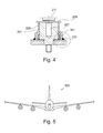
Fig. 4 shows a sealing device according to another exemplary embodiment of the present invention. -
Fig. 5 shows an aircraft according to an exemplary embodiment of the present invention. - The illustration in the drawings is schematically. In different drawings, similar or identical elements are provided with the same reference numerals.
- The following detailed description is merely exemplary in nature and is not intended to limit application and uses. Furthermore, there is no intention to be bound by any theory presented in the preceding background or summary or the following detailed description.
-
Fig. 1 shows a cross-sectional view of a mounting device mounting a monument on astructural element 104 of an aircraft or other means of transportation. The mounting device comprises abushing 107 through which a screw 106 runs which is screwed into acorresponding recess 108 of thestructural element 104. - The
bushing 107 presses against afloor element 109 of the floor of the aircraft. Thefloor element 109 is covered withfloor plates 105. - In order to provide a sealing between the mounting device and the floor, a sealing
element 102 and asilicone seal 103 surround thebushing 107. The sealingelement 102 is pressed onto theflow panels 105 when the screw 106 is screwed into therecess 108 of thestructural element 104, thereby pushing the bushing down towards the floor. - However, the sealing
element 102 and thesilicone seal 103 may be damaged during installation or during use of the monument, for example, bytrolley wheels 101 or other movable equipment. - Furthermore, turning of the
bushing 107 may also lead to a rotation of the sealingelement 102 which may lead to a damage of the seal. -
Fig. 2 shows a cross-sectional view of asealing device 200, which is arranged between astructural element 104 of a means of transport and a mountingdevice monument 300 on thesealing device 200. - The
sealing device 200 comprises a rotationallysymmetrical element 201 in form of a cylinder which comprises one or more steps in its lower region. - The cylindrical element may consist of metal, for example aluminium.
- The lower region of the cylindrical element may comprise two steps, such that the
cylindrical element 201 consists of three cylindrical sections with different diameters. - The upper section has the largest diameter and abuts the surface of the top layer of the
floor 217 of the means of transport. Between thetop layer 217 of the floor and thefloor panel 105, asealing layer 218 in form of a sealing foil, such as a PET-foil, may be provided. - The middle section of the
cylindrical element 201 is arranged in acylindrical recess 203 of the floor and has the same thickness as thefloor - The
lower section 204 of the cylindrical element is adapted in form of a pin with an external thread. Thispin 204 can be screwed into a corresponding recess in thestructural element 104, which comprises a corresponding internal thread. - The upper section of the
cylindrical element 201 comprises arecess 219 with an internal thread, into which thepin 207 of the mountingdevice - The mounting
device lower part 212 of themonument 300 viascrews block 213, arranged on one side of thelower part 212 of the monument, and backplate 216, which is arranged on the other side of the lower part 21. - Furthermore, a sealing
bushing 205 is slipped over thecylindrical body 201 of the sealing device. Thesurface 202 of the upper section of thecylindrical body 201 is smooth in order to allow for thebushing 205 to slide in the direction of the arrows upwards or downwards, i.e., in the direction of the rotational axis of the cylindrical body. - The sealing
bushing 205 comprises an external thread in its upper section onto which ajacket 206 is screwed. Thejacket 206 comprises anupper end plate 208 with a recess in its middle for receiving thepin 207 of the mountingdevice - When the
jacket 206 is turned such that it rotates with respect to the sealingbushing 205 and thecylindrical element 201 and moves upwards, i.e., away from thefloor upper section 211 of the mounting device, theend plate 208 abuts and presses against the upper section of the mountingdevice 211. As a consequence, the sealingbushing 205 is pressed in opposite direction and onto the floor. - The sealing
bushing 205 comprises a ring-like recess in its lower end which receives asealing ring 210, which is pressed onto the upper surface of the floor. - One advantage of this arrangement is that the sealing
ring 210 is not rotated when pressed onto the floor. Thus, mechanical stress on the sealing ring may be reduced. - The sealing may further be improved by an additional, ring-
like sealing 209, for example in form of a silicon seal. - The sealing devices depicted in
Figs. 2 to 4 may be used for retrofitting cabin installations, since they can simply be installed between already existent mounting devices with mountingpins 207 and astructural element 104. - Since the sealing device has a smaller diameter than existing mounting devices, the
outer seal 209 may be protected from trolley wheels. - It should be noted that the sealing
bushing 205 may be made of plastic and thejacket 206 may also be made of plastic. -
Fig. 3 shows a cross-sectional view of asealing device 200 arranged between a monument with its mounting device and a floor which is arranged on top of astructural element 104. - At least the lower part of the peripheral surface of the
cylindrical element 201 comprises an external thread, onto which a sealingjacket 301 is screwed. The sealingjacket 301 may be made of or at least comprises plastic or some other deformable material. Thelower portion 302 of sealingjacket 301 has a concave shape. Theupper portion 303 of the sealingjacket 301 comprises an internal thread for screwing the sealing jacket onto thecylindrical element 301. - No O-ring needs to be provided. The sealing effect is achieved by rotating the sealing
jacket 301 with respect to thecylindrical element 201 such that it moves downwards, i.e., towards the upper surface of thefloor 217. As an additional measure, asilicon seal 209 may be provided between the outer surface of the sealing jacket and the upper surface of thefloor 217. - It is also possible to provide both the sealing
jacket 301 and the sealingbushing 205. This is depicted inFig. 4 . However, in this embodiment, nosecond jacket 206 is depicted, although it may also be provided for pushing the sealingbushing 205 towards the floor. - In this particular embodiment, the sealing
bushing 205 is pushed against the floor when thepin 207 of the mounting device is screwed into thecylindrical body 201, thereby causing theupper part 211 of the mounting device to push against theplate 208, which, in turn, pushes the sealingbushing 205 towards the floor. - It should be noted that a monument of an aircraft cabin, such as a galley, may comprise four or
more sealing devices 200 and mountingdevices -
Fig. 5 shows a means of transport in form of a passenger airplane. The airplane comprises a floor, a monument and a plurality of sealing devices, such as the ones described above. The sealing devices are used for mounting the monument on a structural element of the airplane and for providing a seal between the sealing device and the floor of the airplane. - It should be noted that the term "comprising" does not rule out a plurality. Let it further be noted that features described with reference to one of the above exemplary embodiments can also be used in combination with other features of other exemplary embodiments described above. Moreover, while at least one exemplary embodiment has been presented in the foregoing summary and detailed description, it should be appreciated that a vast number of variations exist.
- It should also be appreciated that the exemplary embodiment or exemplary embodiments are only examples, and are not intended to limit the scope, applicability, or configuration in any way. Rather, the foregoing summary and detailed description will provide those skilled in the art with a convenient roadmap for implementing an exemplary embodiment, it being understood that various changes may be made in the function and arrangement of elements described in an exemplary embodiment without departing from the scope as set forth in the appended claims and their legal equivalents.
Claims (14)
- Sealing device for mounting a monument (300) on a structural element (104) of an aircraft (500) and for providing a seal between the sealing device (200) and a floor (105, 218, 217) ofthe aircraft, the sealing device (100) comprising:a cylindrical element (201) with a top region and a bottom region;wherein the bottom region comprises a first pin (204) for attaching the sealing device to the structural element (104) ofthe aircraft; and
wherein the top region comprises a recess (219) for receiving a second pin (207) of a mounting device (211) of the monument for attaching the monument to the sealing device. - The sealing device of claim 1,
wherein the first pin (204) comprises an external thread for screwing the cylindrical element (201) in the structural element (104) ofthe aircraft. - The sealing device of one ofthe preceding claims,
wherein the recess (219) in the top region of the cylindrical element (201) comprises an internal thread for screwing the second pin (207) of the mounting device (211) ofthe monument, which comprises an external thread, in the cylindrical element (201). - The sealing device of one ofthe preceding claims, further comprising:a first sealing jacket (301) surrounding the cylindrical element (201);wherein the structural element (104) ofthe aircraft (500) is positioned below the floor (105) ofthe aircraft; and
wherein the first sealing jacket comprises a deformable material which provides a seal between the sealing device (100) and the floor (105) ofthe aircraft when the sealing device is attached to the structural element (104) ofthe aircraft and when the first sealing jacket (301) is pressed against the floor (105, 218, 217). - The sealing device of claim 4,
wherein at least a first part of a peripheral surface of the cylindrical element (201) comprises an external thread; and
wherein the first sealing jacket (301) comprises an internal thread for screwing the first sealing jacket on the cylindrical element. - The sealing device of one of claims 4 or 5,
wherein the first sealing jacket (301) comprises a sealing region (302) at its lower end which has a concave shape; and
wherein the sealing region is made of the deformable material. - The sealing device of one of the preceding claims, further comprising:a sealing bushing (205) surrounding the cylindrical element (201);wherein at least a second part of the peripheral surface of the cylindrical element (201) is smooth; and
wherein the sealing bushing (205) is adapted for sliding over the peripheral surface of the cylindrical element (201) and for providing a seal between the sealing device (100) and the floor (105, 218, 217) of the aircraft when the sealing device is attached to the structural element (104) of the aircraft and when the sealing bushing (205) is pressed against the floor. - The sealing device of claim 7, further comprising:a second jacket (206);wherein the sealing bushing (205) comprises an external thread and wherein the second jacket (206) comprises an internal thread for screwing the second jacket (206) on the sealing bushing (205).
- The sealing device of claim 8,
wherein the second jacket (206) comprises an end plate (208) with a recess;
wherein the end plate presses against the mounting device (211) of the monument when the second jacket is turned with respect to the sealing bushing, thus pressing the sealing bushing against the floor (105, 218, 217) when the sealing device (100) is mounted on the structural element (104) of the aircraft; and
wherein the recess is adapted for receiving the second pin (207) of the mounting device (211) of the monument. - The sealing device of one of claims 7 to 9,
wherein the sealing bushing (205) comprises a lower region with a sealing ring (210) for providing the seal. - A monument (300) of an aircraft cabin, comprising:a plurality of sealing devices (200) according to one of claims 1 to 10.
- Monument of claim 11, adapted as a galley (300).
- Means of transport (500), comprising:a floor (105, 218, 217);a monument (300);a plurality of sealing devices (200) according to one of claims 1 to 10 for mounting the monument (300) on a structural element (104) of the means of transport (500) and for providing a seal between the sealing device (200) and the floor (105) of the means of transport.
- Means of transport of claim 13, adapted as an aircraft (500).
Priority Applications (2)
| Application Number | Priority Date | Filing Date | Title |
|---|---|---|---|
| EP12177515.9A EP2690014B1 (en) | 2012-07-23 | 2012-07-23 | Sealing device for galley hard point |
| US13/927,415 US9174735B2 (en) | 2012-07-23 | 2013-06-26 | Sealing device for galley hard point |
Applications Claiming Priority (1)
| Application Number | Priority Date | Filing Date | Title |
|---|---|---|---|
| EP12177515.9A EP2690014B1 (en) | 2012-07-23 | 2012-07-23 | Sealing device for galley hard point |
Publications (2)
| Publication Number | Publication Date |
|---|---|
| EP2690014A1 true EP2690014A1 (en) | 2014-01-29 |
| EP2690014B1 EP2690014B1 (en) | 2016-09-14 |
Family
ID=46603593
Family Applications (1)
| Application Number | Title | Priority Date | Filing Date |
|---|---|---|---|
| EP12177515.9A Not-in-force EP2690014B1 (en) | 2012-07-23 | 2012-07-23 | Sealing device for galley hard point |
Country Status (2)
| Country | Link |
|---|---|
| US (1) | US9174735B2 (en) |
| EP (1) | EP2690014B1 (en) |
Cited By (3)
| Publication number | Priority date | Publication date | Assignee | Title |
|---|---|---|---|---|
| EP3260708A1 (en) * | 2016-06-24 | 2017-12-27 | The Boeing Company | Fluid-tight mechanical fastening system and associated structural assembly |
| DE102017130722A1 (en) * | 2017-12-20 | 2019-06-27 | Airbus Operations Gmbh | Aircraft galley |
| EP3871981A1 (en) * | 2020-02-25 | 2021-09-01 | The Boeing Company | Part edge seal arrangement and joining method |
Families Citing this family (3)
| Publication number | Priority date | Publication date | Assignee | Title |
|---|---|---|---|---|
| US9599138B2 (en) * | 2012-03-28 | 2017-03-21 | B/E Aerospace, Inc. | Aircraft monument integrated attachment device |
| EP3718878B1 (en) * | 2019-04-02 | 2024-02-21 | The Boeing Company | Mechanical fastening system and associated structural assembly and method |
| EP4527737B1 (en) * | 2023-09-22 | 2026-05-20 | B/E Aerospace Uk Ltd | Aircraft Monument Mounting Device |
Citations (8)
| Publication number | Priority date | Publication date | Assignee | Title |
|---|---|---|---|---|
| US4043239A (en) * | 1976-01-16 | 1977-08-23 | General Motors Corporation | Shim nut and screw bolt assembly |
| US4186645A (en) * | 1977-12-02 | 1980-02-05 | General Motors Corporation | Plastic plug, nut and stud fastener assembly |
| DE3122366A1 (en) | 1981-06-05 | 1982-12-23 | Messerschmitt-Bölkow-Blohm GmbH, 8000 München | "CONNECTING DEVICE FOR FIXING INSTALLATION ELEMENTS" |
| US20040037667A1 (en) * | 2002-07-31 | 2004-02-26 | Robert Stephen | Ring-post fastener |
| DE102004012262A1 (en) | 2004-03-12 | 2005-09-29 | Airbus Deutschland Gmbh | Mounting plate e.g. for galley fitting in airplane, has arrangement having horizontal surface assigning thread with horizontal surface has recess where mounting plate covers thread for screwing into thread of arrangement |
| EP1596075A1 (en) * | 2004-05-12 | 2005-11-16 | Jamco Corporation | Three-dimensionally adjustable mounting device |
| EP2003349A1 (en) * | 2007-06-14 | 2008-12-17 | Pratt & Whitney Rocketdyne, Inc. | Locking fastening apparatus |
| EP2436600A2 (en) * | 2010-10-04 | 2012-04-04 | The Boeing Company | Seat track and monument attach fastener |
Family Cites Families (7)
| Publication number | Priority date | Publication date | Assignee | Title |
|---|---|---|---|---|
| US2940784A (en) * | 1956-06-06 | 1960-06-14 | William B Fell | Precision threaded adjustment |
| DE19525392C2 (en) * | 1995-07-12 | 1997-08-07 | Telair Int Cargo Sys Gmbh | Locking element |
| US6042315A (en) * | 1997-10-06 | 2000-03-28 | United Technologies Corporation | Fastener |
| US6024330A (en) * | 1998-05-27 | 2000-02-15 | International Business Machines Corporation | Uni-axial floor anchor and leveler for racks |
| KR100356845B1 (en) * | 2000-06-14 | 2002-10-18 | 현대자동차주식회사 | frame mounting structure for frame body automotive vehicle |
| GB0526084D0 (en) * | 2005-12-21 | 2006-02-01 | Airbus Uk Ltd | An aircraft structure and a fastener for use therewith |
| US7784734B2 (en) * | 2006-10-27 | 2010-08-31 | The Boeing Company | Apparatus and method for rigging slaved and actuated panels with external access |
-
2012
- 2012-07-23 EP EP12177515.9A patent/EP2690014B1/en not_active Not-in-force
-
2013
- 2013-06-26 US US13/927,415 patent/US9174735B2/en active Active
Patent Citations (9)
| Publication number | Priority date | Publication date | Assignee | Title |
|---|---|---|---|---|
| US4043239A (en) * | 1976-01-16 | 1977-08-23 | General Motors Corporation | Shim nut and screw bolt assembly |
| US4186645A (en) * | 1977-12-02 | 1980-02-05 | General Motors Corporation | Plastic plug, nut and stud fastener assembly |
| DE3122366A1 (en) | 1981-06-05 | 1982-12-23 | Messerschmitt-Bölkow-Blohm GmbH, 8000 München | "CONNECTING DEVICE FOR FIXING INSTALLATION ELEMENTS" |
| US20040037667A1 (en) * | 2002-07-31 | 2004-02-26 | Robert Stephen | Ring-post fastener |
| DE102004012262A1 (en) | 2004-03-12 | 2005-09-29 | Airbus Deutschland Gmbh | Mounting plate e.g. for galley fitting in airplane, has arrangement having horizontal surface assigning thread with horizontal surface has recess where mounting plate covers thread for screwing into thread of arrangement |
| WO2005095209A1 (en) | 2004-03-12 | 2005-10-13 | Airbus Deutschland Gmbh | Support device for a galley |
| EP1596075A1 (en) * | 2004-05-12 | 2005-11-16 | Jamco Corporation | Three-dimensionally adjustable mounting device |
| EP2003349A1 (en) * | 2007-06-14 | 2008-12-17 | Pratt & Whitney Rocketdyne, Inc. | Locking fastening apparatus |
| EP2436600A2 (en) * | 2010-10-04 | 2012-04-04 | The Boeing Company | Seat track and monument attach fastener |
Cited By (6)
| Publication number | Priority date | Publication date | Assignee | Title |
|---|---|---|---|---|
| EP3260708A1 (en) * | 2016-06-24 | 2017-12-27 | The Boeing Company | Fluid-tight mechanical fastening system and associated structural assembly |
| US10329008B2 (en) | 2016-06-24 | 2019-06-25 | The Boeing Company | Fluid-tight mechanical fastening system and associated structural assembly |
| AU2017203101B2 (en) * | 2016-06-24 | 2022-04-21 | The Boeing Company | Fluid-tight mechanical fastening system and associated structural assembly |
| DE102017130722A1 (en) * | 2017-12-20 | 2019-06-27 | Airbus Operations Gmbh | Aircraft galley |
| EP3871981A1 (en) * | 2020-02-25 | 2021-09-01 | The Boeing Company | Part edge seal arrangement and joining method |
| US11543029B2 (en) | 2020-02-25 | 2023-01-03 | The Boeing Company | Part edge seal arrangement and joining method |
Also Published As
| Publication number | Publication date |
|---|---|
| US9174735B2 (en) | 2015-11-03 |
| US20140021297A1 (en) | 2014-01-23 |
| EP2690014B1 (en) | 2016-09-14 |
Similar Documents
| Publication | Publication Date | Title |
|---|---|---|
| EP2690014B1 (en) | Sealing device for galley hard point | |
| US8388293B2 (en) | Insulated and sealed cap for a fastener component | |
| US9822808B2 (en) | Penetrated floating nut | |
| EP3263919A1 (en) | Aircraft wall panel with nut insert | |
| EP3260708B1 (en) | Fluid-tight mechanical fastening system and associated structural assembly | |
| US7094968B2 (en) | Fitting for a liquid-tight cable leadthrough | |
| US20170284448A1 (en) | Anti-rotation rivetless nut plate | |
| EP3070347A1 (en) | Self-sealing fixing element | |
| US8567741B2 (en) | Hard coated seat rail | |
| CN110104213B (en) | Wall-mounted satellite adapter | |
| EP3617072B1 (en) | A mounting system for a pressure seal of an aircraft door | |
| JP2013504468A (en) | Radome and apparatus for attaching the radome to an aircraft | |
| EP2465774A1 (en) | Adapter and method for installing monuments | |
| US20220316518A1 (en) | Apparatus and methods for lightning protection and locating of fastener nuts with dielectric materials | |
| US20130214095A1 (en) | Sleeve and rod support for fuel bladder | |
| CN106568354A (en) | Novel heat preservation cylinder with temperature control function | |
| EP4116198B1 (en) | Aircraft fuel tank isolator | |
| US20160016666A1 (en) | Modular Mounting Structure with Embedded Electrical Bus | |
| CN101618767A (en) | Method for rapidly disassembling radome on airplane and rotating locks | |
| EP3257754A1 (en) | Lightning strike dispersion for composite aircraft structures | |
| EP3212500B1 (en) | Installation system for aft aircraft monument assembly | |
| US20200023933A1 (en) | Pressure bulkhead and method of installation | |
| CN103956695A (en) | Via hole protection part for wiring harness | |
| US20160340050A1 (en) | Molded insert for enhanced pulll-out strength | |
| CN102717894A (en) | Fixing structure of external onboard photoelectric pod on fixed-wing aircraft |
Legal Events
| Date | Code | Title | Description |
|---|---|---|---|
| PUAI | Public reference made under article 153(3) epc to a published international application that has entered the european phase |
Free format text: ORIGINAL CODE: 0009012 |
|
| AK | Designated contracting states |
Kind code of ref document: A1 Designated state(s): AL AT BE BG CH CY CZ DE DK EE ES FI FR GB GR HR HU IE IS IT LI LT LU LV MC MK MT NL NO PL PT RO RS SE SI SK SM TR |
|
| AX | Request for extension of the european patent |
Extension state: BA ME |
|
| 17P | Request for examination filed |
Effective date: 20140318 |
|
| RBV | Designated contracting states (corrected) |
Designated state(s): AL AT BE BG CH CY CZ DE DK EE ES FI FR GB GR HR HU IE IS IT LI LT LU LV MC MK MT NL NO PL PT RO RS SE SI SK SM TR |
|
| 17Q | First examination report despatched |
Effective date: 20160114 |
|
| REG | Reference to a national code |
Ref country code: DE Ref legal event code: R079 Ref document number: 602012022725 Country of ref document: DE Free format text: PREVIOUS MAIN CLASS: B64D0011000000 Ipc: F16B0033000000 |
|
| GRAJ | Information related to disapproval of communication of intention to grant by the applicant or resumption of examination proceedings by the epo deleted |
Free format text: ORIGINAL CODE: EPIDOSDIGR1 |
|
| GRAP | Despatch of communication of intention to grant a patent |
Free format text: ORIGINAL CODE: EPIDOSNIGR1 |
|
| RIC1 | Information provided on ipc code assigned before grant |
Ipc: B64D 11/00 20060101ALI20160413BHEP Ipc: F16B 33/00 20060101AFI20160413BHEP Ipc: F16B 35/06 20060101ALI20160413BHEP |
|
| INTG | Intention to grant announced |
Effective date: 20160518 |
|
| GRAS | Grant fee paid |
Free format text: ORIGINAL CODE: EPIDOSNIGR3 |
|
| GRAA | (expected) grant |
Free format text: ORIGINAL CODE: 0009210 |
|
| AK | Designated contracting states |
Kind code of ref document: B1 Designated state(s): AL AT BE BG CH CY CZ DE DK EE ES FI FR GB GR HR HU IE IS IT LI LT LU LV MC MK MT NL NO PL PT RO RS SE SI SK SM TR |
|
| REG | Reference to a national code |
Ref country code: GB Ref legal event code: FG4D |
|
| REG | Reference to a national code |
Ref country code: CH Ref legal event code: EP |
|
| REG | Reference to a national code |
Ref country code: IE Ref legal event code: FG4D |
|
| REG | Reference to a national code |
Ref country code: AT Ref legal event code: REF Ref document number: 829341 Country of ref document: AT Kind code of ref document: T Effective date: 20161015 |
|
| REG | Reference to a national code |
Ref country code: DE Ref legal event code: R096 Ref document number: 602012022725 Country of ref document: DE |
|
| REG | Reference to a national code |
Ref country code: LT Ref legal event code: MG4D |
|
| REG | Reference to a national code |
Ref country code: NL Ref legal event code: MP Effective date: 20160914 |
|
| PG25 | Lapsed in a contracting state [announced via postgrant information from national office to epo] |
Ref country code: FI Free format text: LAPSE BECAUSE OF FAILURE TO SUBMIT A TRANSLATION OF THE DESCRIPTION OR TO PAY THE FEE WITHIN THE PRESCRIBED TIME-LIMIT Effective date: 20160914 Ref country code: LT Free format text: LAPSE BECAUSE OF FAILURE TO SUBMIT A TRANSLATION OF THE DESCRIPTION OR TO PAY THE FEE WITHIN THE PRESCRIBED TIME-LIMIT Effective date: 20160914 Ref country code: NO Free format text: LAPSE BECAUSE OF FAILURE TO SUBMIT A TRANSLATION OF THE DESCRIPTION OR TO PAY THE FEE WITHIN THE PRESCRIBED TIME-LIMIT Effective date: 20161214 Ref country code: RS Free format text: LAPSE BECAUSE OF FAILURE TO SUBMIT A TRANSLATION OF THE DESCRIPTION OR TO PAY THE FEE WITHIN THE PRESCRIBED TIME-LIMIT Effective date: 20160914 Ref country code: HR Free format text: LAPSE BECAUSE OF FAILURE TO SUBMIT A TRANSLATION OF THE DESCRIPTION OR TO PAY THE FEE WITHIN THE PRESCRIBED TIME-LIMIT Effective date: 20160914 |
|
| REG | Reference to a national code |
Ref country code: AT Ref legal event code: MK05 Ref document number: 829341 Country of ref document: AT Kind code of ref document: T Effective date: 20160914 |
|
| PG25 | Lapsed in a contracting state [announced via postgrant information from national office to epo] |
Ref country code: GR Free format text: LAPSE BECAUSE OF FAILURE TO SUBMIT A TRANSLATION OF THE DESCRIPTION OR TO PAY THE FEE WITHIN THE PRESCRIBED TIME-LIMIT Effective date: 20161215 Ref country code: SE Free format text: LAPSE BECAUSE OF FAILURE TO SUBMIT A TRANSLATION OF THE DESCRIPTION OR TO PAY THE FEE WITHIN THE PRESCRIBED TIME-LIMIT Effective date: 20160914 Ref country code: LV Free format text: LAPSE BECAUSE OF FAILURE TO SUBMIT A TRANSLATION OF THE DESCRIPTION OR TO PAY THE FEE WITHIN THE PRESCRIBED TIME-LIMIT Effective date: 20160914 Ref country code: NL Free format text: LAPSE BECAUSE OF FAILURE TO SUBMIT A TRANSLATION OF THE DESCRIPTION OR TO PAY THE FEE WITHIN THE PRESCRIBED TIME-LIMIT Effective date: 20160914 |
|
| PG25 | Lapsed in a contracting state [announced via postgrant information from national office to epo] |
Ref country code: RO Free format text: LAPSE BECAUSE OF FAILURE TO SUBMIT A TRANSLATION OF THE DESCRIPTION OR TO PAY THE FEE WITHIN THE PRESCRIBED TIME-LIMIT Effective date: 20160914 Ref country code: EE Free format text: LAPSE BECAUSE OF FAILURE TO SUBMIT A TRANSLATION OF THE DESCRIPTION OR TO PAY THE FEE WITHIN THE PRESCRIBED TIME-LIMIT Effective date: 20160914 |
|
| PG25 | Lapsed in a contracting state [announced via postgrant information from national office to epo] |
Ref country code: SM Free format text: LAPSE BECAUSE OF FAILURE TO SUBMIT A TRANSLATION OF THE DESCRIPTION OR TO PAY THE FEE WITHIN THE PRESCRIBED TIME-LIMIT Effective date: 20160914 Ref country code: BG Free format text: LAPSE BECAUSE OF FAILURE TO SUBMIT A TRANSLATION OF THE DESCRIPTION OR TO PAY THE FEE WITHIN THE PRESCRIBED TIME-LIMIT Effective date: 20161214 Ref country code: PL Free format text: LAPSE BECAUSE OF FAILURE TO SUBMIT A TRANSLATION OF THE DESCRIPTION OR TO PAY THE FEE WITHIN THE PRESCRIBED TIME-LIMIT Effective date: 20160914 Ref country code: ES Free format text: LAPSE BECAUSE OF FAILURE TO SUBMIT A TRANSLATION OF THE DESCRIPTION OR TO PAY THE FEE WITHIN THE PRESCRIBED TIME-LIMIT Effective date: 20160914 Ref country code: SK Free format text: LAPSE BECAUSE OF FAILURE TO SUBMIT A TRANSLATION OF THE DESCRIPTION OR TO PAY THE FEE WITHIN THE PRESCRIBED TIME-LIMIT Effective date: 20160914 Ref country code: PT Free format text: LAPSE BECAUSE OF FAILURE TO SUBMIT A TRANSLATION OF THE DESCRIPTION OR TO PAY THE FEE WITHIN THE PRESCRIBED TIME-LIMIT Effective date: 20170116 Ref country code: BE Free format text: LAPSE BECAUSE OF FAILURE TO SUBMIT A TRANSLATION OF THE DESCRIPTION OR TO PAY THE FEE WITHIN THE PRESCRIBED TIME-LIMIT Effective date: 20160914 Ref country code: IS Free format text: LAPSE BECAUSE OF FAILURE TO SUBMIT A TRANSLATION OF THE DESCRIPTION OR TO PAY THE FEE WITHIN THE PRESCRIBED TIME-LIMIT Effective date: 20170114 Ref country code: AT Free format text: LAPSE BECAUSE OF FAILURE TO SUBMIT A TRANSLATION OF THE DESCRIPTION OR TO PAY THE FEE WITHIN THE PRESCRIBED TIME-LIMIT Effective date: 20160914 Ref country code: CZ Free format text: LAPSE BECAUSE OF FAILURE TO SUBMIT A TRANSLATION OF THE DESCRIPTION OR TO PAY THE FEE WITHIN THE PRESCRIBED TIME-LIMIT Effective date: 20160914 |
|
| REG | Reference to a national code |
Ref country code: DE Ref legal event code: R097 Ref document number: 602012022725 Country of ref document: DE |
|
| PG25 | Lapsed in a contracting state [announced via postgrant information from national office to epo] |
Ref country code: IT Free format text: LAPSE BECAUSE OF FAILURE TO SUBMIT A TRANSLATION OF THE DESCRIPTION OR TO PAY THE FEE WITHIN THE PRESCRIBED TIME-LIMIT Effective date: 20160914 |
|
| PLBE | No opposition filed within time limit |
Free format text: ORIGINAL CODE: 0009261 |
|
| STAA | Information on the status of an ep patent application or granted ep patent |
Free format text: STATUS: NO OPPOSITION FILED WITHIN TIME LIMIT |
|
| REG | Reference to a national code |
Ref country code: FR Ref legal event code: PLFP Year of fee payment: 6 |
|
| PG25 | Lapsed in a contracting state [announced via postgrant information from national office to epo] |
Ref country code: DK Free format text: LAPSE BECAUSE OF FAILURE TO SUBMIT A TRANSLATION OF THE DESCRIPTION OR TO PAY THE FEE WITHIN THE PRESCRIBED TIME-LIMIT Effective date: 20160914 |
|
| 26N | No opposition filed |
Effective date: 20170615 |
|
| PG25 | Lapsed in a contracting state [announced via postgrant information from national office to epo] |
Ref country code: SI Free format text: LAPSE BECAUSE OF FAILURE TO SUBMIT A TRANSLATION OF THE DESCRIPTION OR TO PAY THE FEE WITHIN THE PRESCRIBED TIME-LIMIT Effective date: 20160914 |
|
| REG | Reference to a national code |
Ref country code: CH Ref legal event code: PL |
|
| GBPC | Gb: european patent ceased through non-payment of renewal fee |
Effective date: 20170723 |
|
| REG | Reference to a national code |
Ref country code: IE Ref legal event code: MM4A |
|
| PG25 | Lapsed in a contracting state [announced via postgrant information from national office to epo] |
Ref country code: IE Free format text: LAPSE BECAUSE OF NON-PAYMENT OF DUE FEES Effective date: 20170723 Ref country code: CH Free format text: LAPSE BECAUSE OF NON-PAYMENT OF DUE FEES Effective date: 20170731 Ref country code: GB Free format text: LAPSE BECAUSE OF NON-PAYMENT OF DUE FEES Effective date: 20170723 Ref country code: LI Free format text: LAPSE BECAUSE OF NON-PAYMENT OF DUE FEES Effective date: 20170731 |
|
| PG25 | Lapsed in a contracting state [announced via postgrant information from national office to epo] |
Ref country code: LU Free format text: LAPSE BECAUSE OF NON-PAYMENT OF DUE FEES Effective date: 20170723 |
|
| REG | Reference to a national code |
Ref country code: FR Ref legal event code: PLFP Year of fee payment: 7 |
|
| PG25 | Lapsed in a contracting state [announced via postgrant information from national office to epo] |
Ref country code: MT Free format text: LAPSE BECAUSE OF NON-PAYMENT OF DUE FEES Effective date: 20170723 |
|
| PG25 | Lapsed in a contracting state [announced via postgrant information from national office to epo] |
Ref country code: AL Free format text: LAPSE BECAUSE OF FAILURE TO SUBMIT A TRANSLATION OF THE DESCRIPTION OR TO PAY THE FEE WITHIN THE PRESCRIBED TIME-LIMIT Effective date: 20160914 |
|
| PG25 | Lapsed in a contracting state [announced via postgrant information from national office to epo] |
Ref country code: HU Free format text: LAPSE BECAUSE OF FAILURE TO SUBMIT A TRANSLATION OF THE DESCRIPTION OR TO PAY THE FEE WITHIN THE PRESCRIBED TIME-LIMIT; INVALID AB INITIO Effective date: 20120723 Ref country code: MC Free format text: LAPSE BECAUSE OF FAILURE TO SUBMIT A TRANSLATION OF THE DESCRIPTION OR TO PAY THE FEE WITHIN THE PRESCRIBED TIME-LIMIT Effective date: 20160914 |
|
| PG25 | Lapsed in a contracting state [announced via postgrant information from national office to epo] |
Ref country code: CY Free format text: LAPSE BECAUSE OF NON-PAYMENT OF DUE FEES Effective date: 20160914 |
|
| PGFP | Annual fee paid to national office [announced via postgrant information from national office to epo] |
Ref country code: DE Payment date: 20190719 Year of fee payment: 8 Ref country code: FR Payment date: 20190719 Year of fee payment: 8 |
|
| PG25 | Lapsed in a contracting state [announced via postgrant information from national office to epo] |
Ref country code: MK Free format text: LAPSE BECAUSE OF FAILURE TO SUBMIT A TRANSLATION OF THE DESCRIPTION OR TO PAY THE FEE WITHIN THE PRESCRIBED TIME-LIMIT Effective date: 20160914 |
|
| PG25 | Lapsed in a contracting state [announced via postgrant information from national office to epo] |
Ref country code: TR Free format text: LAPSE BECAUSE OF FAILURE TO SUBMIT A TRANSLATION OF THE DESCRIPTION OR TO PAY THE FEE WITHIN THE PRESCRIBED TIME-LIMIT Effective date: 20160914 |
|
| REG | Reference to a national code |
Ref country code: DE Ref legal event code: R119 Ref document number: 602012022725 Country of ref document: DE |
|
| PG25 | Lapsed in a contracting state [announced via postgrant information from national office to epo] |
Ref country code: FR Free format text: LAPSE BECAUSE OF NON-PAYMENT OF DUE FEES Effective date: 20200731 |
|
| PG25 | Lapsed in a contracting state [announced via postgrant information from national office to epo] |
Ref country code: DE Free format text: LAPSE BECAUSE OF NON-PAYMENT OF DUE FEES Effective date: 20210202 |